
FMA-36I4HD/DVO - Air-conditioner TCL - Free user manual and instructions
Find the device manual for free FMA-36I4HD/DVO TCL in PDF.

User questions about FMA-36I4HD/DVO TCL
0 question about this device. Answer the ones you know or ask your own.
Ask a new question about this device
Download the instructions for your Air-conditioner in PDF format for free! Find your manual FMA-36I4HD/DVO - TCL and take your electronic device back in hand. On this page are published all the documents necessary for the use of your device. FMA-36I4HD/DVO by TCL.
USER MANUAL FMA-36I4HD/DVO TCL
SPLIT TYPE AIR CONDITIONER INSTRUCTION MANUAL
(For Multi split)
natural_image
Line drawing of a rectangular air conditioner unit (no text or symbols)This instruction manual contains important information and recommendations that we would ask you to comply with to obtain best results from air conditioner.
Thank you once again.
CONTENTS
SAFETY PRECAUTIONS ....1
NAMES OF PARTS 4
INDOOR UNIT DISPLAY 5
EMERGENCY FUNCTION & AUTO-RESTART FUNCTION....6
REMOTE CONTROLLER....7
OPERATING INSTRUCTIONS ....11
INSTALLATION MANUAL....20
MAINTENANCE 35
TROUBLESHOOTING 36
SAFETY RULES AND RECOMMENDATIONS FOR THE INSTALLER

The ratings of the fuse installed in the built in control unit are 4A / 250V.

The appliance must be fitted with means for disconnection from the supply mains having a contact separation in all poles that provide full disconnection under overvoltage category III conditions, and these means must be incorporated in the fixed wiring in accordance with the wiring rules.

Only use the air conditioner as instructed in this booklet.

The appliance must be installed in accordance with applicable national regulations.

Before accessing the terminals, all the power circuits must be disconnected from the power supply.

The appliance shall be installed in accordance with national wiring regulations.
SAFETY RULES AND RECOMMENDATIONS FOR THE USER
⚠️ Cleaning and maintenance must be carried out by specialized technical personnel. In any case disconnect the appliance from the mains electricity supply before carrying out any cleaning or maintenance.
This appliance has been made for air conditioning domestic environments and must not be used for any other purpose.
The batteries in remote controller must be recycled or disposed of properly.
⚠️ If the appliance gives off smoke or there is a smell of burning, immediately cut off the power supply and contact the Service Centre.
Have repairs carried out only by an authorised Service Centre of the manufacturer. Incorrect repair could expose the user to the risk of electric shock, etc.
Unhook the automatic switch if you foresee not to use the device for a long time. The airflow direction must be properly adjusted
SAFETY RULES AND PROHIBITIONS
Do not obstruct the air inlet or outlet of the indoor or the outdoor unit. The obstruction of these openings causes a reduction in the operative efficiency of the conditioner with possible consequent failures or damages.
This appliance is not intended for use by persons (including children) with reduced physical, sensory or mental capabilities, or lack of experience and knowledge, unless they have been given supervision or instruction concerning use of the appliance by a person responsible for their safety.
Children should be supervised to ensure that they do not play with the appliance. If the supply cord is damaged, it must be replaced by the manufacturer, its service agent or similarly qualified persons in order to avoid a hazard.
- Air Intake
- Front Panel
- Electrostatic Filter (optional)
- Air Filter
- Display Panel
- Air Outlet
- Emergency Panel
- Vertical Adjustment Louver
- Charcoal Filter (optional)
- Horizontal Adjustment Louver
- Air Intake
12 .Drain Hose Note: Condensate water drains at COOLING or DRY operation.
13 .Pipes and Power Connection Cord
-
Air Outlet
-
Remote Controller
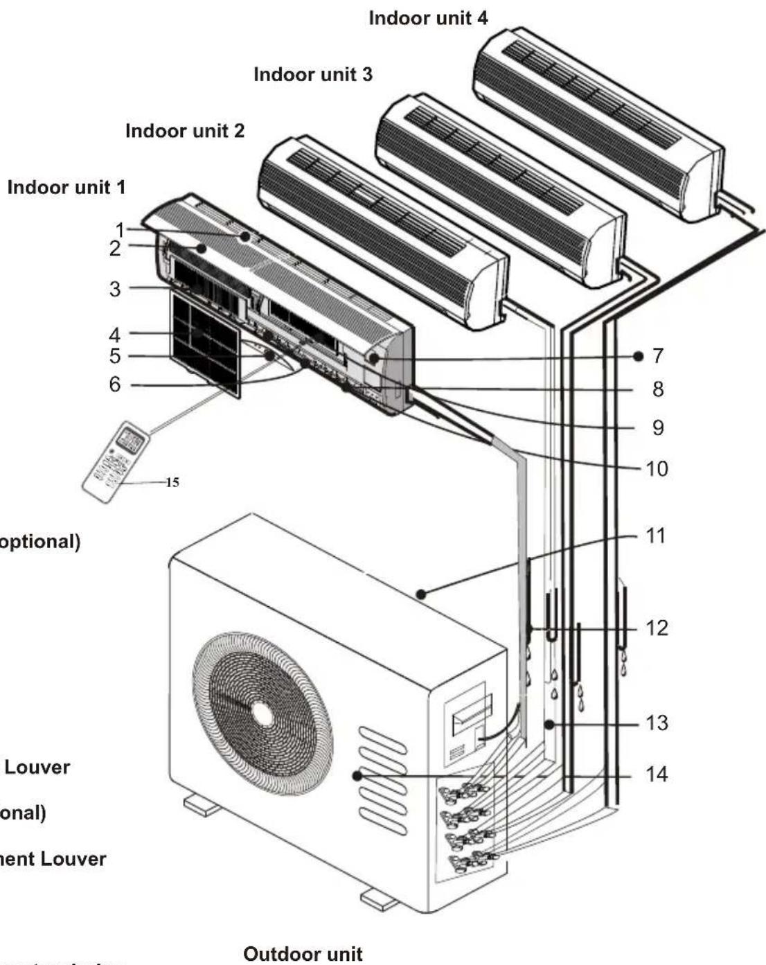
Note: the above figures are only intended to be a simple diagram of the appliance and may not correspond to the appearance of the units that have been purchased.
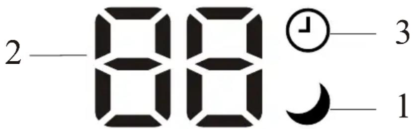
| No. | Led | Function | |
| 1 | SLEEP | SLEEP mode | |
| 2 | Temperature display (if present)/Error code | (1) Lights up during Timer operation when the air conditioner is operational(2)Displays the malfunction code when fault occurs. | |
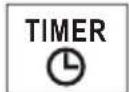
| 3 | TIMER | Lights up during Timer operation. |

The shape and position of switches and indicators may be different according to the model, but their function is the same.
EMERGENCY FUNCTION & AUTO-RESTART FUNCTION
EMERGENCY FUNCTION
If the remote controller fails to work or maintenance necessary, proceed as following:
Open and lift the front panel up to an angle to reach the emergency button.
For heating model, press the emergency button first and the unit will operate in COOL mode. Press for a second time within 3 seconds, and unit will operate in HEAT mode. Press for third after 5 seconds, the unit will turn off.
For cooling only models, press the emergency button once, and the unit will operate in COOL mode. Press again, the unit will turn off.
AUTO-RESTART FUNCTION
The appliance is preset with an auto-restart function. In case of a sudden power failure, the module will memorizes the setting conditions before the power failure. When the power restores, the unit will restart automatically with the previous settings preserved by the memory function.

The emergency button is located on E-box cover of the unit under the front panel.
The shape and position of the emergency button may be different according to the model, but their function is the same.
For ON/OFF models For inverter models
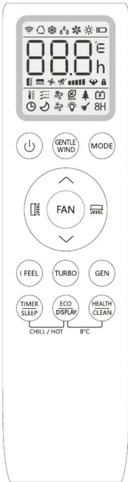
REMOTE CONTROLLER
Remote controller buttons
| No. | Buttons Function | |
| 1 | To turn on/off the air conditioner | |
| 2 | GENTLE WIND | To activate the function of Gentle wind. |
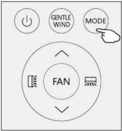
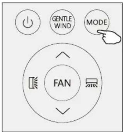
| 3 | MODE | To select the operation mode: AUTO, COOL, DRY, FAN, HEAT. |
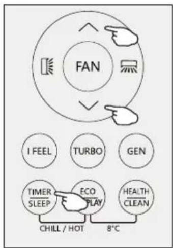
| 4 | (TEMP UP) | To increase the setting temperature, lengthen the time in TIMER setting. |
| 5 | (TEMP DN) | To decrease the setting temperature, reduce the time in TIMER setting. |
| 6 | To adjust the air flow direction vertically(optional). | |
| 7 | To adjust the air flow direction horizontally. | |
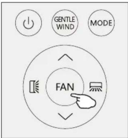
| 8 | FAN | To adjust the fan speed: auto, mute, low, mid-low, mid, mid-hign, high. Turbo |
| 9 | I FEEL | To activate the function of I FEEL |
| 10 | I SET | To activate the function of I SET |
| 11 | TURBO | To switch on/off the TURBO mode |
| 12 | GEN | To switch on/off the GENERATOR mode |
| 13 | TIMER/SLEEP | To switch on/off the TIMER function and SLEEP mode |
| 14 | ECO/DISPLAY | To switch on/off the ECO mode and LED display light |
| 15 | HEALTH/CLEAN | To switch on/off the HEALTH function and Auto Clean function.. |
| 16 | TIMER/SLEEP + ECO/DISPLAY | To switch on/off the CHILL WIND and HOT WIND fucntion. |
| 17 | ECO/DISPLAY + HEALTH/CLEAN | To switch on/off the CHILL WIND and HOT WIND fucntion. |
| 18 |  | To activate the function of Child Lock, press and buttons together for more than 3 seconds. |
The display and some functions of the remote control may vary according to the model.
The shape and position of buttons and indicators may vary according to the model, but their function is the same.
The unit confirms the correct reception of each button with a beep.
Certain functions may not be available for your air conditioner.
The batteries in remote controller must be recycled or disposed of properly.
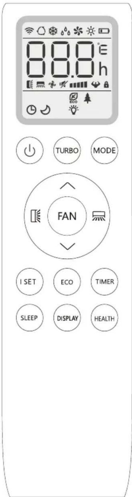
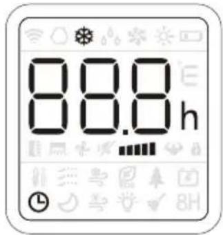
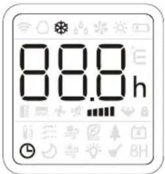
REMOTE CONTROLLER
Remote controller DISPLAY, meaning of symbols on the liquid crystal display
| No. | Symbols | Meaning |
| 1 |  | AUTO MODE indicator |
| 2 | [40XX] | COOLING MODE indicator |
| 3 | [C0Z5] | DRY MODE indicator |
| 4 |  | FAN MODE indicator |
| 5 | [A242] | HEATING MODE indicator |
| 6 | [420S] | BATTERY indicator |
| 7 | [020S] | TEMPERATURE/ CLOCK indicator |
| 8 | [26HH] | FLAP SWING (Air flow) indicator |
| 9 |  | MUTE indicator |
| 10 | [DB0Y] | FAN SPEED indicator |
| 11 |  | AUTO FAN indicator |
| 12 |  | TURBO indicator |
| 13 |  | CHILD LOCK indicator |
| 14 |  | I FEEL indicator |
| 15 |  | GENTLE WIND indicator |
| 16 | [3CA2] | CHILL WIND indicator |
| 17 | [4672] | ECO indicator |
| 18 | [407C] | HEALTHY indicator |
| 19 | [Y04A] | GENERATOR MODE indicator |
| 20 | [DOC0] | TIMER indicator |
| 21 | [22C0] | SLEEP MODE indicator |
| 22 | [3000] | HOT WIND indicator |
| 23 | [DDVT] | DISPLAY LIGHT indicator |
| 24 | [40CW] | CLEAN function indicator |
| 25 | [XXT] | 8°C heating function indicator |
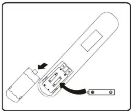
REMOTE CONTROLLER
Replacement of Batteries
Remove the battery cover plate from the rear of the remote controller, by sliding it in the direction of the arrow.
Install the batteries according the direction (+and -) shown on the Remote Controller.
Reinstall the battery cover by sliding it into place.
⚠️ Use 2 LRO 3 AAA (1.5V) batteries. Do not use rechargeable batteries. Replace the old batteries with new ones of the same type when the display is no longer legible.
Do not dispose batteries as unsorted municipal waste. Collection of such waste separately for special treatment is necessary.
natural_image
Diagram of a remote control device with labeled ports and internal components (no text or symbols)Recommendations for locating and using the remote controller holder (if present).
The remote controller be kept in a wall-mounted holder.
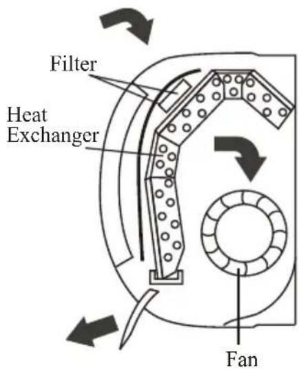
OPERATING INSTRUCTIONS
The air sucked by the fan enters from the grill and passes through the filter, then it is cooled/dehumidified or heated through the heat exchanger.
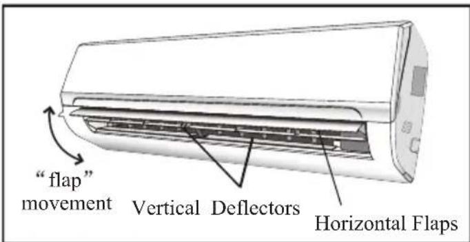
The direction of the air outlet is motorized up and down by flaps, and manually moved right and left by the vertical deflectors, for some models, the vertical deflectors could be controlled by motor as well.
Turn ON / Turn OFF the air conditioner
Press the button

to turn on or turn off the air conditioner.
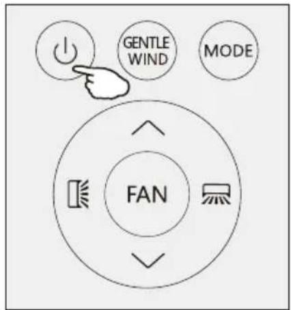
COOLING MODE
The cooling function allows the air conditioner to cool the room and at the same time reduces Air humidity.
To activate the cooling function (COOL), press the MODE button until the symbol ✿ appears on the display.
With the button √ or ∧ set a temperature lower than that of the room.
OPERATING INSTRUCTIONS
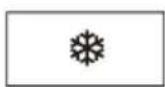
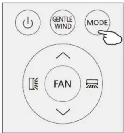
HEATING MODE
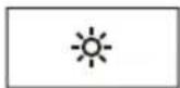
The heating function allows the air conditioner to heat the room.
To activate the heating function (HEAT), press the MODE button until the symbol ⚙️ appears on the display.
With the button √ or ∧ set a temperature higher than that of the room.

In HEATING operation, the appliance can automatically activate a defrost cycle, which is essential to clean the frost on the condenser so as to recover its heat exchange function. This procedure usually lasts for 2-10 minutes. During defrosting, indoor unit fan stop operation. After defrosting, it resumes to HEATING mode automatically.
DRY MODE
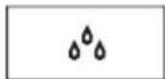
This function reduces the humidity of the air to make the room more comfortable.
To set the DRY mode, Press MODE until _0 appears in the display. An automatic function of pre-setting is activated.
FAN MODE(Not FAN button)
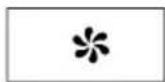
Fan mode, air ventilation only.
To set the FAN mode, press MODE until * appears on the display.
AUTO MODE
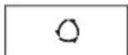
Automatic mode.
To set the AUTO mode, press MODE until appears on the display.
In AUTO mode the run mode will be set automatically according to the room temperature.
OPERATING INSTRUCTIONS
Press FAN button to set the running fan speed, it can be set to AUTO/ MUTE/ LOW/ MID-LOW/ MID/ MID-HI/ HIGH/TURBO speed.
Flashing

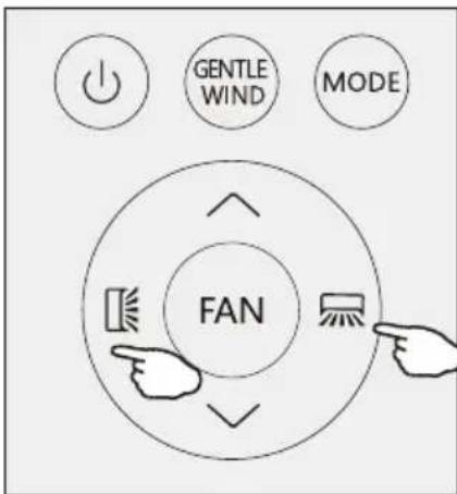
AIR FLOW CONTROL
- Normal 4 way air flow (vertical and horizontal):
(1) Press ☐ to activate the horizontal flaps to swing from up to down. Press again to stop the swing movement at the current angle.
(2) Press ☐ to active the vertical deflectors to swing from left to right. Press again to stop the swing movement at the current angle.
- Vector precise air flow
(1)Press [icon] and hold for 1s, it will go into the horizontal vector air flow, you can select a small swing angle you want:
$$ \square^ {\prime} \triangleright \square^ {-} \triangleright \square - \triangleright \square_ {-} \triangleright \square_ {1} \triangleright \square = \triangleright \square = $$
Stop selection for 5s, press 📁 again, exit the horizontal vector precise air flow.
(2) Press ☐ and hold for 1s, it will go into the vertical vector air flow:

Stop selection for 5s, press ☐ again, exit the vertical vector precise air flow.
- If the vertical deflectors are positioned manually which placed under the flaps, they are allowed to move the air flow direct to rightward or leftward.
This adjustment must be done while the appliance is switched off.
Never position "Flaps" manually, the delicate mech-anism might seriously damaged!
⚠️ Never poke fingers, sticks or other objects in the air inlet or outlet vents. Such accidental contact with liveparts might cause unforeseeable damage or injury.
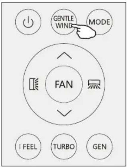
GENTLE WIND (Optimal)
In this mode the appliance will close its vertical louvers, the air flow through the holes of louvers, the room is cool but no winds.
Press the GENTLE WIND button shortly, the ≡ appears on the display, and the appliance will run in GENTLE WIND mode. Press again to cancel it..
NOTE:
The gentle wind function is available in COOLING mode only.
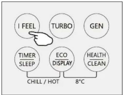
I FEEL function
I FEEL
Press I FEEL button to active the function, the will appear on the remote display. Do it again to deactivate this function.
This function enables the remote control to measure the temperature at its current location, and send this signal to the air conditioner to optimize the temperature around you and ensure the comfort.
It will automatically deactivate 2 hours later.
flowchart
graph TD
    A["I FEEL"] --> B["TURBO"]
    C["GEN"] --> D["TIMER SLEEP"]
    E["ECO DISPLAY"] --> F["HEALTH CLEAN"]
    G["CHILL / HOT"] --> H["8°C"]
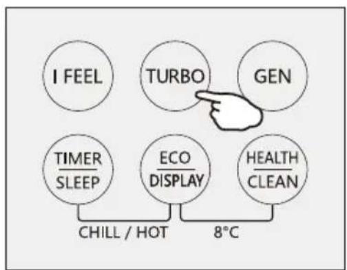
Turbo function

To activate turbo function, press the TURBO button, and 🎨 will appear on the display.
Press again to cancel this function.
In COOL/HEAT mode, when you select TURBO feature, the appliance will operate the fast cooling/fast heating with the highest fan speed.
flowchart
graph TD
    A["I FEEL"] --> B["TURBO"]
    C["GEN"] --> D["TURBO"]
    E["TIMER SLEEP"] --> F["ECO DISPLAY"]
    G["HEALTH CLEAN"] --> H["ECO DISPLAY"]
    B --> I["8°C"]
    D --> I
    F --> I
    H --> I
    I --> J["CHILL / HOT"]
OPERATING INSTRUCTIONS
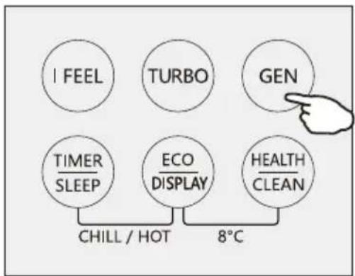
GENERATOR MODE (Optional)

The air conditioner works in generator mode, it is helpful for the unstable net power area.
Through GEN mode, you can choose the current level of the unit. There are three levels (L1, L2, L3) in this mode, and the current increases in turn.
To activate GEN function, pressing the button GEN and the unit current level will cycle as below OFF-E3 L2-L1 → "
Running current (% of rated current):
L1: 30%, L2: 50%, L3: 70%
To cancel this function, press the GEN until code OF appears on the display.
SLEEP MODE

Pre-setting automatic operating program.
Press SLEEP button and hold for 2s to activate the sleep mode, and 🙏 appears on the display. Press and hold for 2s again to cancel this mode.
In sleep mode, the air conditioner will automatically adjust the temperature and fan speed to make the room more comfortable during the night.
After 10 hours running in sleep mode, the air conditioner will change to the previous setting mode.
ECO MODE

In this mode the appliance automatically sets the operation to save energy.
Press the ECO button, the 📄 appears on the display, and the appliance will run in ECO mode. Press again to cancel it..
NOTE:
The ECO function is available in both COOLING and HEATING modes.
flowchart
graph TD
    A["I FEEL"] --> B["CHILL / HOT"]
    C["TURBO"] --> D["8°C"]
    E["GEN"] --> F["HEALTH CLEAN"]
    G["TIMER SLEEP"] --> H["ECO DISPLAY"]
    I["HEAD"] --> J["Hand pointing to Gen"]
flowchart
graph TD
    A["I FEEL"] --> B["TURBO"]
    B --> C["GEN"]
    D["TIMER SLEEP"] --> E["ECO DISPLAY"]
    E --> F["HEALTH CLEAN"]
    G["CHILL / HOT"] --> H["8°C"]
flowchart
graph TD
    A["I FEEL"] --> B["TURBO"]
    C["GEN"] --> D["TIMER SLEEP"]
    D --> E["ECO DISPLAY"]
    F["HEALTH CLEAN"] --> G["CHILL / HOT"]
    G --> H["8°C"]
OPERATING INSTRUCTIONS
LED display light ON/OFF
Press DISPLAY button and hold for 2s to turn on/off the indoor LED display light.
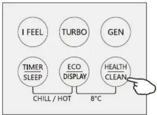
HEALTH function (Optional)
Press HEALTH button to active / exit the health functions such as ion generator/ plasma etc
Note: Health function is not available when the air conditioner is off.
SELF-CLEAN function (Optional)
- This function help carry away the accumulated dirt, bacteria, etc from the evaporator.
- Turn off the air conditioner, press "CLEAN" button to enter this function and it will show "CL" on the display of indoor unit.
- This function will run about 30 minutes, and it will exit automatically. You will hear 2 beeps when it's finished or cancelled.
- It's normal if there are some noise during this function process, as plastic materials expand with heat and contract with cold.
- We suggest operate this function as the following ambient condition to avoid certain safety protection features.
| Indoor unit | Temp<30°C |
| Outdoor unit | 5°C |
- We suggest operate this function once every 3 months.
flowchart
graph TD
    A["I FEEL"] --> B["TURBO"]
    B --> C["GEN"]
    D["TIMER SLEEP"] --> E["ECO DISPLAY"]
    F["HEALTH CLEAN"] --> G["8°C"]
    H["CHILL / HOT"] --> I["Chill / Hot"]
flowchart
graph TD
    A["I FEEL"] --> D["CHILL / HOT"]
    B["TURBO"] --> D
    C["GEN"] --> D
    E["TIMER SLEEP"] --> D
    F["ECO DISPLAY"] --> D
    G["HEALTH CLEAN"] --> D
    D --> H["8°C"]
flowchart
graph TD
    A["I FEEL"] --> D["CHILL / HOT"]
    B["TURBO"] --> D
    C["GEN"] --> D
    E["TIMER SLEEP"] --> D
    F["ECO DISPLAY"] --> D
    G["HEALTH CLEAN"] --> D
    D --> H["8°C"]
OPERATING INSTRUCTIONS
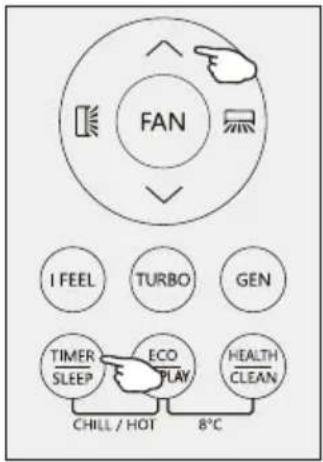
TIMER MODE----SET TIMER OFF
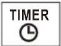
To set the air conditioner switching-off automatically.
With the AC on, press the Timer button and then use the ^ and ∨ buttons to set the length of time before the AC will turn off. Press the timer button again to start the countdown.
Note: To cancel the sets function of MER button again.
Note: In case of power off, it is necessary to set TIMER OFF again
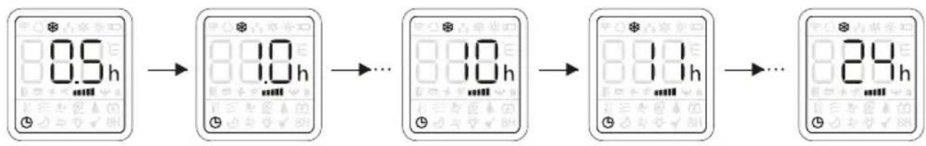
flowchart
graph LR
    A["0.5h"] --> B["1.0h"]
    B --> C["..."]
    C --> D["1.0h"]
    D --> E["1.1h"]
    E --> F["..."]
    F --> G["24h"]
TIMER MODE----SET TIMER ON
To set the air conditioner switching-on automatically.
With the AC off, press the Timer button and use the ∧ and ∨ buttons to set the desired amount of time before the AC turns on. Press the timer button again to start the countdown.
When the timer setting was done, you can set the operation mode, fan speed, desired temperature, air flow when air conditioner star to run.
Note: To cancel the timer function, press the TIMER button again.
Note: In case of power off, it is necessary to set TIMER ON again
OPERATING INSTRUCTIONS
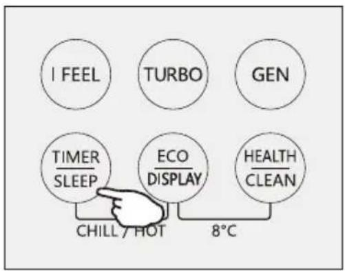
CHILL wind/ HOT wind function (Optional)
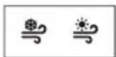
- In cooling mode, press both TIMER/SLEEP and ECO/DISPLAY buttons and hold for 2s to active the chill wind function.
- In heating mode, press both TIMER/SLEEP and ECO/DISPLAY buttons and hold for 2s to active the hot wind function.
- Press both TIMER/SLEEP and ECO/DISPLAY buttons and hold for 2s to exit the chill wind or hot wind function.
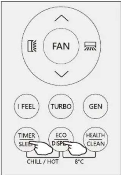
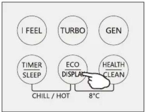
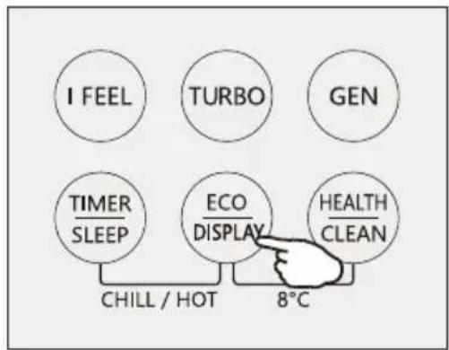
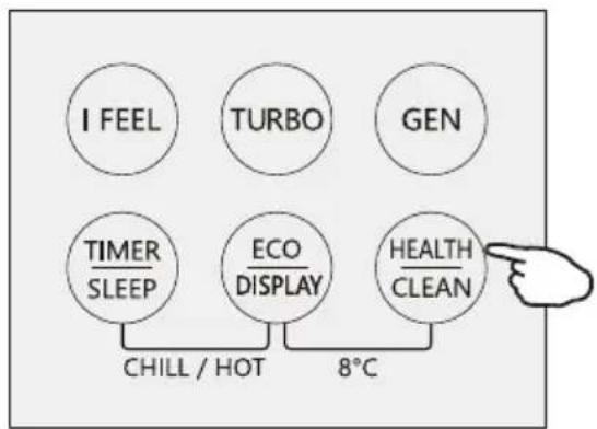
8°Heating function (Optional)
8H
- Press both ECO/DISPLAY and HEALTH/CLEAN buttons and hold for 2s to active the 8° heating.
- If the air conditioner is standby, this function enable the air conditioner automatically start heating when the indoor temperature is equal or lower than 8C it will return standby if the temperature is equal or higher than 18C.
- When the AC was turn off, press both ECO/DISPLAY and HEALTH/CLEAN buttons and hold for 2s to exit the 8°heating.
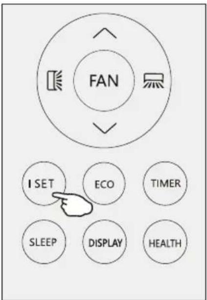
I SET function(Optional)
In each mode of COOLING/HEATING/FAN/DRY, adjust the temperature(COOLING/HEATING), fan speed (COOLING/HEATING/FAN) and swing as your favourite, then keep pressing "I SET" button over 3 seconds until "AU" appears on the display and the background of display change to lighting, the remote controller will run and remember these settings. You can reset it by repeat the above operation.
In each mode of COOLING/HEATING/FAN/DRY, press "I SET" button to active this function, the AC will run as your favourite setting and you will see AU flashing on the remote controller. Press it again or other buttons to cancel this function.
Operating Temperature
The air conditioner is programmed for comfortable and suitable living conditions as below if used outside the conditions, certain safety protection features might come into effect.,
Fix air conditioner:
| MODE Temperature | Cooling operating | Heating operating | Drying operating |
| Room temperature | 17°C32 °C | 0°C27 °C | 17°C32 °C |
| Outdoor temperature | 15°C43 °C For T1 Climate | -7°C24 °C | 15°C43 °C For T1 Climate |
| 15°C52 °C For T3 Climate | 15°C52 °C For T3 Climate |
Inverter air conditioner:
| MODE Temperature | Cooling operating | Heating operating | Drying operating |
| Room temperature | 17°C32 0°C30 17 ~32 | °C °C | °C °C |
| Outdoor temperature | 15°C53 °C | -20°C30 °C | 15°C53 °C |
| -15°C53 °C For models with low temperature cooling system | -15°C53 °C For models with low temperature cooling system |
The unit does not operate immediately if it is turned on after being turned off or after changing the mode during operation. This is a normal self-protection action, you need to wait for about minutes.
The capacity and efficiency are according to the test conducted at full-load operation(The highest speed of indoor fan motor and the maximum open angle of the flaps and deflectors are requested.)
INSTALLATION MANUAL---Important considerations for R32/R290
Special Tools
| Tool Name Requirement(s) for Use | |
| Mini Vacuum Pump | It should be an explosion-proof vacuum pump; can ensure certain precision and its vacuum degree should be lower than 10Pa. |
| Filling Device | It should be a special explosion-proof filling device; have certain precision and its filling deviation should be less than 5g. |
| Leak Detector | It should be calibrated regularly; and its annual leak rate should not exceed 10g. |
| Concentration Detector | A) The maintenance site should be equipped with a fixed-type combustible refrigerant concentration detector and connected to a safeguard alarm system; its error must be not more than 5%.B) The installation site should be equipped with a portable combustible refrigerant concentration detector which can realize two-level audible and visual alarm; its error must be not more than 10%.C) The concentration detectors should be calibrated regularly.D) It is necessary to check and confirm the functions before using the concentration detectors. |
| Pressure Gauge | A) The pressure gauges should be calibrated regularly.B) The pressure gauge used for Refrigerant 22 can be used for Refrigerants R290 and R161; the pressure gauge used for R410A can be used for Refrigerant 32. |
| Fire Extinguisher | It is necessary to carry fire extinguisher(s) when installing and maintaining an air conditioner. On the maintenance site, there should be two or more kinds of dry powder, carbon dioxide and foam fire extinguishers and that such fire extinguishers should be placed at stipulated positions, with eye-catching labels and in handy places. |
INSTALLATION MANUAL---Important considerations for R32/R290
Installation Safety Principles
1. Site Safety

Open Flames Prohibited Ventilation Necessary
2. Operation Safety
Open Flames Prohibited


Mind Static Electricity
Must wear protective clothing and anti-static gloves Don't use mobile phone
3. Installation Safety
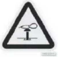
● Refrigerant Leak Detector
● Appropriate Installation Location

The left picture is the schematic diagram of a refrigerant leak detector.
Please note that:
- The installation site should be in a well-ventilated condition.
- The sites for installing and maintaining an air conditioner using Refrigerant R290 should be free from open fire or welding, smoking, drying oven or any other heat source higher than 370°C which easily produces open fire; the sites for installing and maintaining an air conditioner using Refrigerant R32 should be free from open fire or welding, smoking, drying oven or any other heat source higher than 548°C which easily produces open fire.
- When installing an air conditioner, it is necessary to take appropriate anti-static measures such as wear anti-static clothing and/or gloves.
- It is necessary to choose the site convenient for installation or maintenance wherein the air inlets and outlets of the indoor and outdoor units should be not surrounded by obstacles or close to any heat source or combustible and/or explosive environment.
- If the indoor unit suffers refrigerant leak during the installation, it is necessary to immediately turn off the valve of the outdoor unit and all the personnel should go out till the refrigerant leaks completely for 15 minutes. If the product is damaged, it is a must to carry such damaged product back to the maintenance station and it is prohibited to weld the refrigerant pipe or conduct other operations on the user's site.
- It is necessary to choose the place where the inlet and outlet air of the indoor unit is even.
- It is necessary to avoid the places where there are other electrical products, power switch plugs and sockets, kitchen cabinet, bed, sofa and other valuables right under the lines on two sides of the indoor unit.
The maximum charge and the required minimum floor area
$$ m _ {1} = \left(4 m ^ {3}\right) \times L F L, m _ {2} = \left(2 6 m ^ {3}\right)) \times L F L, m _ {3} = \left(1 3 0 m ^ {3}\right) \times L F L $$
Where
$$ L F L ^ {3}, $$
3
is the lower ^3 flami
For the appliances with a charge amount m_1 < M = m_2 :
The maximum charge in a room shall be in accordance with the following: m_=2.5×(LFL)^(5/4)× h_0×(A)^1/2
The required minimumfloor area Amin to install an appliance with refrigerant charge M (kg) shall be in accordance with following: A_ = (M / (2.5 × (LFL)^(5/4) × h_0))^2
Where:
m_max is the allowable maximum charge in a room, in kg;
Mis the refrigerant charge amount in appliance, in kg;
Amin is the required minimum room area, in m2;
A is the room area, in m^2 ;
LFL is the lower flammable limit, in kg/m ^3 ;
h_0 is the installation height of the appliance, in meters for calculating m_max or A_min , 1.8 m for wall mounted;
Table GG.1 - Maximum charge (kg)
| Category | LFL (kg/m3) | h0(m) | Floor area (m2) | ||||||
| 4 | 7 | 10 | 15 | 20 | 30 | 50 | |||
| R290 | 0.038 | 0.6 | 0.05 | 0.07 | 0.08 | 0.1 | 0.11 | 0.14 | 0.18 |
| 1 | 0.08 | 0.11 | 0.13 | 0.16 | 0.19 | 0.2 | 0.3 | ||
| 1.8 | 0.15 | 0.2 | 0.24 | 0.29 | 0.34 | 0.41 | 0.53 | ||
| 2.2 | 0.18 | 0.24 | 0.29 | 0.36 | 0.41 | 0.51 | 0.65 | ||
| R32 | 0.306 | 0.6 | 0.68 | 0.9 | 1.08 | 0.32 | 1.53 | 1.87 | 2.41 |
| 1 | 1.14 | 1.51 | 1.8 | 2.2 | 2.54 | 3.12 | 4.02 | ||
| 1.8 | 2.05 | 2.71 | 3.24 | 3.97 | 4.58 | 5.61 | 7.254 | ||
| 2.2 | 2.5 | 3.31 | 3.96 | 4.85 | 5.6 | 6.86 | 8.85 | ||
Table GG.2 - Minimum room area ( m^2 )
| Category | LFL (kg/m3) | h0(m) | Charge amount (M) (kg) Minimum room area (m2) | ||||||
| R290 | 0.038 | 0.152kg | 0.228kg | 0.304kg | 0.456kg | 0.608kg | 0.76kg | 0.988kg | |
| 0.6 | 82 | 146 | 328 | 584 | 912 | 1514 | |||
| 1 | 30 | 53 | 118 | 210 | 328 | 555 | |||
| 1.8 | 9 | 16 | 36 | 65 | 101 | 171 | |||
| 2.2 | 6 | 11 | 24 | 43 | 68 | 115 | |||
| R32 | 0.306 | 1.224kg | 1.836kg | 2.448kg | 3.672kg | 4.896kg | 6.12kg | 7.956kg | |
| 0.6 | 29 | 51 | 116 | 206 | 321 | 543 | |||
| 1 | 10 | 19 | 42 | 74 | 116 | 196 | |||
| 1.8 | 3 | 6 | 13 | 23 | 36 | 60 | |||
| 2.2 | 2 | 4 | 9 | 15 | 24 | 40 | |||
INSTALLATION MANUAL---Important considerations for R32/R290
■ Important Considerations
- The air conditioner you buy must be installed by professional personnel and the "Installation manual" is used only for the professional installation personnel! The installation specifications should be subject to our after-sale service regulations.
- When filling the combustible refrigerant, any of your rude operations may cause serious injury or injuries to human body or bodies and object or objects.
● A leak test must be done after the installation is completed.
- It is a must to do the safety inspection before maintaining or repairing an air conditioner using combustible refrigerant in order to ensure that the fire risk is reduced to minimum.
- It is necessary to operate the machine under a controlled procedure in order to ensure that any risk arising from the combustible gas or vapor during the operation is reduced to minimum.
- Requirements for the total weight of filled refrigerant and the area of a room to be equipped with an air conditioner (are shown as in the following Tables GG.1 and GG.2)

INSTALLATION MANUAL---Selecting the Installation Place
INDOOR UNIT
• Install the indoor unit on a strong wall that is not subject to vibrations.
- The in let and outlet ports should not be obstructed: the air should be able to blow all over the room.
- Do not install the unit near a source of heat, steam, or flammable gas.
- Do not install the unit where it will be exposed to direct sunlight.
- Select a site where the condensed water can be easily drained out, and where it is easily connected to outdoor unit.
- Check the machine operation regularly and reserve the necessary spaces as shown in the picture.
- Select a place where the filter can be easily taken out.
minimum space to be reserved (mm) showing in the picture
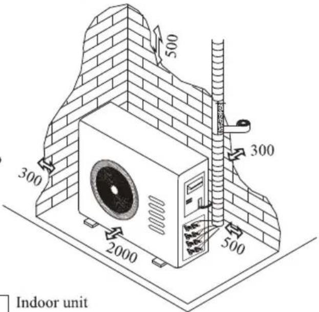
OUTDOOR UNIT
- Do not install the outdoor unit near sources of heat, steam or flammable gas.
- Do not install the unit in too windy or dusty places.
- Do not install the unit where people often pass. Select a place where the air discharge and operating sound will not disturb the neighbours.
- Avoid installing the unit where it will be exposed to direct sunlight (other wise use a protection, if necessary, that should not interfere with the air flow).
- Reserve the spaces as shown in the picture for the air to circulate freely.
• Install the outdoor unit in a safe and solid place. - If the outdoor unit is subject to vibration, place rubber gaskets onto the feet of the unit..
Installation Diagram
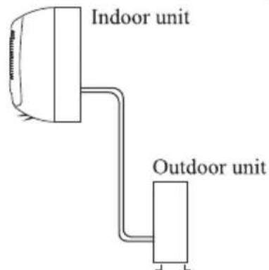
The purchaser must ensure that the person and/or company who is to install, maintain or repair this air conditioner has qualifications and experience in refrigerant products.
INSTALLATION MANUAL---Installation of the Indoor unit
Before starting installation, decide on the position of the indoor and outdoor units, taking into account the minimum space reserved around the units

Do not install your air conditioner in a wet room such as a bathroom or laundry etc

The installation site should be 250cm or more above the floor.
To install, proceed as follows:
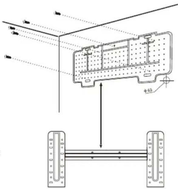
Installation of the mounting plate
- Always mount the rear panel horizontally and vertically
- Drill 32 mm deep holes in the wall to fix the plate;
- Insert the plastic anchors into the hole;
- Fix the rear panel on the wall with provided tapping screws
- Be sure that the rear panel has been fixed firmly enough to withstand the weight.
Note : The shape of the mounting plate may be different from the one above, but installation method is similar.
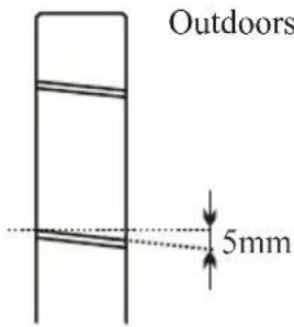
Drilling a hole in the wall for the piping
- Make the piping hole (65) in the wall at a slight downward slant to the outdoor side.
- Insert the piping-hole sleeve into the hole to prevent the connection piping and wiring from being damaged when passing through the hole.
The hole must slope downwards towards the exterior
Note : Keep the drain pipe down towards the direction of the wall hole, otherwise leakage may occur.

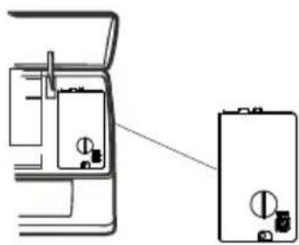
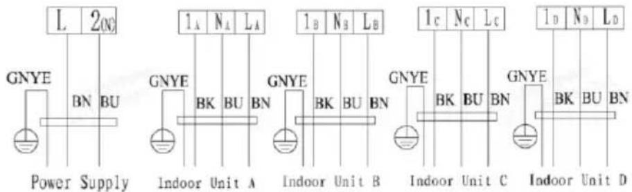
Electrical connections---Indoor unit
- Open the front panel.
- Take off the cover as indicated in the picture (by removing a screw or breaking the hooks).
- For the electrical connections, see the circuit diagram on the right part of the unit under the front panel.
- Connect the cable wires to the screw terminals by following the numbering, Use wire size suitable to the electric power input (see name plate on the unit) and according to all current national safety code requirements.

The cable connecting the outdoor and indoor units must be suitable for outdoor use.

The plug must be accessible also after the appliance has been installed so that it can be pulled out if necessary.

An efficient earth connection must be ensured.

If the power cable is damaged, it must be replaced by an authorised Service Centre.
Note: Optional the wires can be connected to the main PCB of indoor unit by manufacturer according to the model without terminal block.
Indoors
natural_image
Technical line drawing of a mechanical device with internal components and a separate view showing a cylindrical component (no text or symbols)INSTALLATION MANUAL---Installation of the Indoor unit
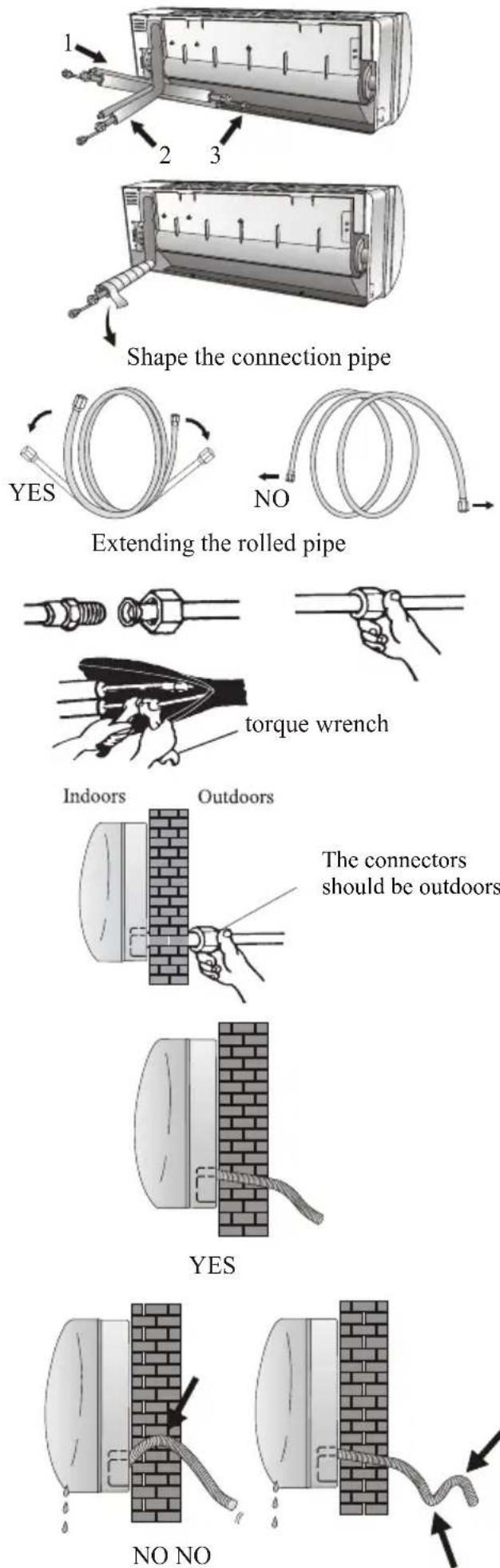
Refrigerant piping connection
The piping can be run in the 3 directions indicated by numbers in the picture. When the piping is run in direction 1 or 3, cut a notch along the groove on the side of the indoor unit with a cutter.
Run the piping in the direction of the wall hole and bind the copper pipes, the drain pipe and the power cables together with the tape with the drain pipe at the bottom, so that water can flow freely.
- Do not remove the cap from the pipe until connecting it, to avoid dampness or dirt from entering.
- If the pipe is bent or pulled too often, it will become stiff. Do not bend the pipe more than three times at one point.
- When extending the rolled pipe, straighten the pipe by unwinding it gently as shown in the picture.
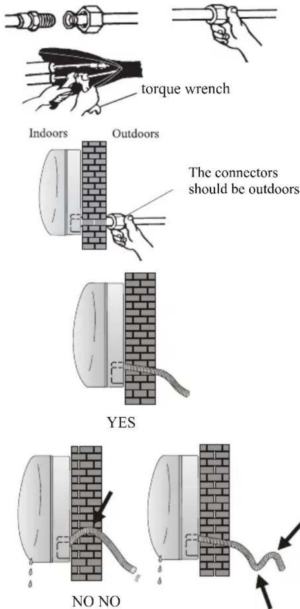
Connections to the indoor unit
- Remove the indoor unit pipe cap (check that there is no debris inside).
- Insert the fare nut and create a flange at the extreme end of the connection pipe.
- Tighten the connections by using two wrenches working in opposite directions.
- For R32/R290 refrigerants, mechanical connectors should be outdoors.
Indoor unit condensed water drainage
The indoor unit condensed water drainage is fundamental for the success of the installation.
- Place the drain hose below the piping, taking care not to create siphons.
- The drain hose must slant downwards to aid drainage.
- Do not bend the drain hose or leave it protruding or twisted and do not put the end of it in water. If an extension is connected to the drain hose, ensure that it is lagged when it passes into the indoor unit.
- If the piping is installed to the right, the pipes, power cable and drain hose must be lagged and secured onto the rear of the unit with a pipe connection.
1) Insert the pipe connection into the relative slot.
2) Press to join the pipe connection to the base.
INSTALLATION MANUAL---Installation of the Indoor unit
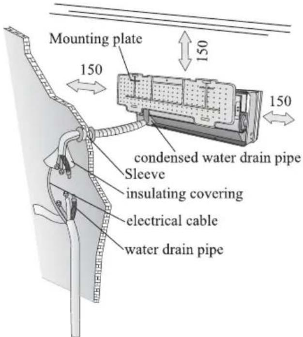
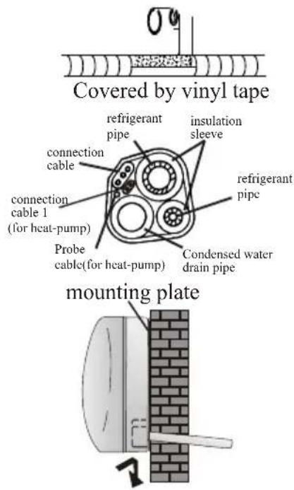
INSTALLATION OF THE INDOOR UNIT
After having connected the pipe according to the instructions, install the connection cables. Now install the drain pipe. After connection, lag the pipe, cables and drain pipe with the insulating material.
- Arrange the pipes, cables and drain hose well.
- Lag the pipe joints with insulating material, securing it with vinyl tape.
- Run the bound pipe, Cables and drain pipe through the wall hole and mount the indoor unit onto the upper part of the mounting plate securely.
- Press and push the lower part of the indoor unit tightly against the mounting plate
Sometimes, if the refrigerant piping is already embedded in the wall, or if you want to connecting the piping and wiring on the wall, do as below:
- Gab both ends of the bottom plate, apply a little outward force to take off the bottom plate.
- Hook the top of the indoor unit on the mounting plate without piping and wiring.
- Lift the indoor unit opposite the wall, unfold the bracket on the mounting plate, and use this bracket to prop up the indoor unit, there will be a big space for operation.
- Do the refrigerant piping, wiring, connect drainage hose, and wrap them as Step 4 to 7.
- Replace the bracket of mounting plate.
- Push down the bottom of indoor unit to let the snaps onto the bottom hooks of the mounting plate, and make sure it is hooked firmly.
- Replace the bottom plate of the indoor unit.
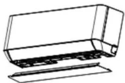
natural_image
Line drawing of a mechanical component with no visible text or symbolsTake off the bottom plate

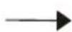
natural_image
Simple line drawing of a 3D geometric object resembling a cube or block, with no text or symbols present.Unfold the bracket on the mounting plate
INSTALLATION MANUAL---Installation of the outdoor unit
- The outdoor unit should be installed on a solid wall and fastened securely.
- The following procedure must be observed before connecting the pipes and connecting cables: decide which is the best position on the wall and leave enough space to be able to carry out maintenance easily.
- Fasten the support to the wall using screw anchors which are particularly suited to the type of wall;
- Use a larger quantity of screw anchors than normally required for the weight they have to bear to aviod vibration during operation and remain fastened in the same position for years without the screws becoming loose.
- The unit must be installed following the national regulations.
- The outdoor unit should be installed on a solid wall and fastened securely, of on the ground on a flat/level surface like a concrete slab. The bolt size is M8*80mm.
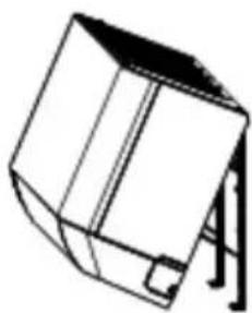
Outdoor unit condensed water drainage (only for heat pump models)
The condensed water and the ice formed in the outdoor unit during heating operation can be drained away through the drain pipe
- Fasten the drain port in the 25mm hole placed in the part of the unit as shown in the picture.
- Connect the drain port and the drain pipe. Pay attention that water is drained in a suitable place.
INSTALLATION MANUAL---Installation of the outdoor unit
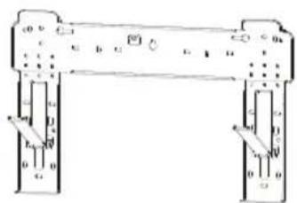
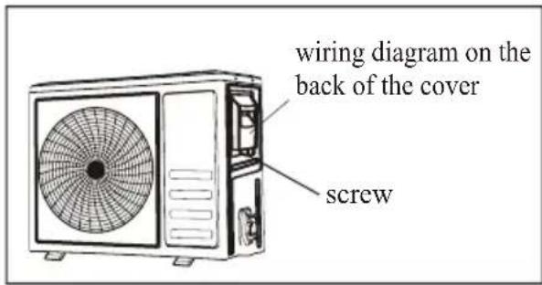
ELECTRICAL CONNECTIONS
- Remove the handle on the right side plate of outdoor unit.
- Connect the power connection cord to the terminal board. Wiring should fit that of indoor unit.
- Fix the power connection cord with wire clamp.
- Confirm if the wire has been fixed properly.
- An efficient earth connection must be ensured.
- Recover the handle.
- The appliance must be fitted with means for disconnection from the supply mains having a contact separation in all poles that provide full disconnection under over voltage category III conditions, and these means must be incorporated in the fixed wiring in accordance with the wiring rules.
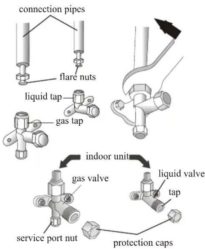
CONNECTING THE PIPES
Screw the flare nuts to the outdoor unit coupling with the same tightening procedures described for the indoor unit.
To avoid leakage, pay attention to the following points:
- Tighten the flare nuts using two wrenches. Pay attention not to damage the pipes.
- If the tightening torque is not sufficient, there will probably be some leakage. With excessive tightening torque there will also be some leakage, as the flange could be damaged.
- The surest system consists in tightening the connection by using a fix wrench and a torque wrench as below:
| PIPE Size | Newton meter [N x m] | Pound-force foot (1bf-ft) | Kilogram-force meter (kgf-m) |
| 1/4" (6.35) | 18 - 20 | 24.4 - 27.1 | 2.4 - 2.7 |
| 3/8" (9.52) | 30 - 35 | 40.6 - 47.4 | 4.1 - 4.8 |
| 1/2" (12) | 45 - 50 | 61.0 - 67.7 | 6.2 - 6.9 |
| 5/8" (45.88) | 60 - 65 | 81.3 - 88.1 | 8.2 - 8.9 |
INSTALLATION MANUAL---Installation of the outdoor unit
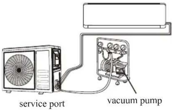
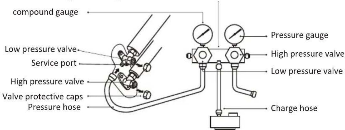
Air Vacuumizing
- Use a spanner to take down the protective caps from the service port, low pressure valve and high pressure valve of the outdoor unit.
- Connect the pressure hose of manifold gauge to the service port on the outdoor unit low pressure valve.
- Connect the charge hose from the manifold gauge to the vacuum pump.
- Open the low pressure valve of the manifold gauge and close the high pressure valve.
- Turn on the vacuum pump to vacuumize the system.
- The vacuuming time should not be less than 15 minutes, or make sure the compound gauge indicates -0.1 MPa (-76 cmHg)
- Close the low pressure valve of the manifold gauge and turn off the vacuum.
- Hold the pressure for 5 minutes, make sure that the rebound of compound gauge pointer does not exceed 0.005 Mpa.
- Turn the low pressure valve counterclockwise for 1/4 turn with hexagonal wrench to let a little refrigerant fill in the system, and close the low pressure valve after 5 seconds and quickly remove the pressure hose.
- Check all indoor and outdoor joints for leakage with soapy water or leak detector.
- Fully open the low pressure valve and high pressure valve of the outdoor unit with hexagonal wrench.
- Replace the protective caps of the service port, low pressure valve and high pressure valve of the outdoor unit.
- Replace the valve cover.
Refrigerant Pressure Inspection
Air-returning Low-pressure Range of Refrigerant R290: 0.4-0.6Mpa; Air-exhausting High-pressure Range: 1.5-2.0Mpa;
Air-returning Low-pressure Range of Refrigerant R32:
0.8-1.2Mpa; Air-exhausting High-pressure Range:
3.2-3.7Mpa;
It means that the refrigerating system or refrigerant of an air conditioner is abnormal if the air-exhausting and air-returning pressure ranges of the detected compressor exceed the normal ranges to a large extent.
Manifold gauge
Vacuum pump
INSTALLATION MANUAL---Installation of the outdoor unit
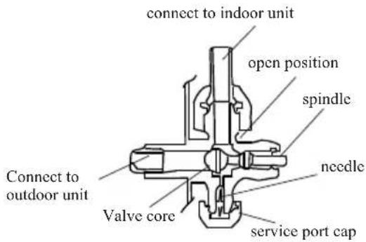
BLEEDING
The air and humidity left inside the refrigerant circulation can cause compressor malfunction. After having connected the indoor and outdoor units, bleed the air and humidity from the refrigerant circulation using a vacuum pump.
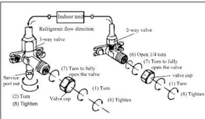
(1) Unscrew and remove the caps from the 2 - way and 3-way valves.
(2) Unscrew and remove the cap from the service port.
(3) Connect the vacuum pump hose to the service port.
(4) Operate the vacuum pump for 10 - 15 minutes until an absolute vacuum of 10mmHg has been reached.
(5) With the vacuum pump still in operation, close the low - pressure knob on the vacuum pump coupling. Stop the vacuum pump.
(6) Open the 2 - way valve by 1/4 turn and then close it after 10 seconds. Check all the joints for leaks using liquid soap or an electronic leak device.
(7) Turn the body of the 2-way and 3-way valves. Disconnect the vacuum pump hose.
(8) Replace and tighten all the caps on the valves.
3-way valve diagram
flowchart
graph TD
    A["Indoor unit"] --> B["3-way valve"]
    B --> C["Service port nut"]
    C --> D["(2) Turn"]
    D --> E["(8) Tighten"]
    E --> F["Valve cap"]
    F --> G["(7) Turn to fully open the valve"]
    G --> H["(1) Turn"]
    H --> I["(8) Tighten"]
    I --> J["(6) Open 1/4 turn"]
    J --> K["(7) Turn to fully open the valve"]
    K --> L["(valve cap)"]
    L --> M["(1) Turn"]
    M --> N["(8) Tighten"]
    N --> O["(6) Open 1/4 turn"]
    O --> P["(7) Turn to fully open the valve"]
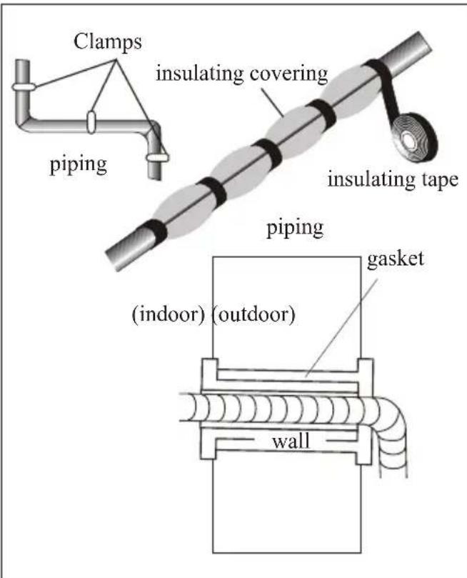
INSTALLATION MANUAL--- operation test
- Wind insulating covering around the joints of the indoor unit and fix it with insulating tape.
- Fix the exceeding part of the signal cable to the piping or to the outdoor unit.
- Fix the piping to the wall (after having coated it with insulating tape) using clamps or insert them into plastic slots.
- Seal the hole in the wall through which the piping is passed so that no air or water can fill.
Indoor unit test
- Do the ON/OFF and FAN operate normally?
- Does the MODE operate normally?
- Do the set point and TIMER function properly?
- Does each lamp light normally?
- Do the flap for air flow direction operate normally?
• Is the condensed water drained regularly?
Outdoor unit test
- Is there any abnormal noise or vibration during operation?
• Could the noise, the air flow or the condensed water drainage disturb the neighbours?
• Is there any coolant leakage?
Note: the electronic controller allows the compressor to start only three minutes after voltage has reached the system.
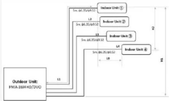
INSTALLATION MANUAL---Information for the installer
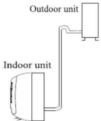
Pipe length and Additional refrigerant
flowchart
graph TD
    A["Outdoor Unit: FMA-36H4 HD/DVO"] --> B["Indoor Unit ①"]
    A --> C["Indoor Unit ②"]
    A --> D["Indoor Unit ③"]
    A --> E["Indoor Unit ④"]
    B --> F["Indoor Unit ①"]
    B --> G["Indoor Unit ②"]
    B --> H["Indoor Unit ③"]
    B --> I["Indoor Unit ④"]
    C --> J["Indoor Unit ②"]
    C --> K["Indoor Unit ③"]
    C --> L["Indoor Unit ④"]
    D --> M["Indoor Unit ③"]
    D --> N["Indoor Unit ④"]
    E --> O["Indoor Unit ③"]
    E --> P["Indoor Unit ④"]
    style A fill:#f9f,stroke:#333
    style B fill:#ccf,stroke:#333
    style C fill:#ccf,stroke:#333
    style D fill:#ccf,stroke:#333
    style E fill:#ccf,stroke:#333
    style F fill:#fff,stroke:#333
    style G fill:#fff,stroke:#333
    style H fill:#fff,stroke:#333
    style I fill:#fff,stroke:#333
    style J fill:#fff,stroke:#333
    style K fill:#fff,stroke:#333
    style L fill:#fff,stroke:#333
    style M fill:#fff,stroke:#333
    style N fill:#fff,stroke:#333
    style O fill:#fff,stroke:#333
    style P fill:#fff,stroke:#333
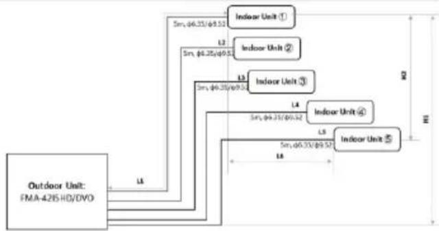
flowchart
graph TD
    A["Outdoor Unit: FMA-4215 HD/DVD"] --> B["Indoor Unit ①"]
    A --> C["Indoor Unit ②"]
    A --> D["Indoor Unit ③"]
    A --> E["Indoor Unit ④"]
    A --> F["Indoor Unit ⑤"]
    B --> G["5m, φ6.35/φ9.51"]
    C --> H["5m, φ6.25/φ9.51"]
    D --> I["5m, φ6.35/φ9.51"]
    E --> J["5m, φ6.35/φ9.52"]
    F --> K["5m, φ6.35/φ9.52"]
    style A fill:#f9f,stroke:#333
    style B fill:#ccf,stroke:#333
    style C fill:#ccf,stroke:#333
    style D fill:#ccf,stroke:#333
    style E fill:#ccf,stroke:#333
    style F fill:#ccf,stroke:#333
| Model | FMA-36I4HD/DVO | FMA-42I5HD/DVO | |
| Min. piping length (outdoor to indoor) | L1, L2, (L3), (L4), (L5) | 3m | 3m |
| Standard piping length (outdoor to indoor) | L1, L2, (L3), (L4), (L5) | 5m | 5m |
| Max. piping length (outdoor to indoor) | L1, L2, (L3), (L4), (L5) | 20m | 20m |
| Max. Total piping length | L1+L2 (+L3)(+L4)(+L5) | 60m | 80m |
| Precharged total piping length | L1+L2 (+L3)(+L4)(+L5) | 40m | 55m |
| Connection pipe | TAC-09CHSD/TPH11-I | 6.35/ 9.52 | 6.35/ 9.52 |
| TAC-12CHSD/TPH11-I | 6.35/ 9.52 | 6.35/ 9.52 | |
| TAC-18CHSD/TPH11-I | 6.35/ 12.7 | 6.35/ 12.7 | |
| TAC-24CHSD/TPH11-I | 6.35/ 12.7 | 6.35/ 12.7 | |
| Additional refrigerant charge (gramm/m) | R410a/20g | R410a/20g | |
| Max. Lenght difference (nearest indoor to farthest) | L6 | No requirement | No requirement |
| Max. Height difference (outdoor to higher indoor) | H1 | 15m | 15m |
| Max. Height difference (lower indoor to higher indoor) | H2 | No requirement | No requirement |
| Min. Number of connectable indoor units | 2 | 2 | |
| Min. Connectable capacity (indoor unit) | 9K/2640W | 7K/2000W | |
Note:
When the matching indoor unit model is TAC-18CHSD/TPH11-I or TAC-24CHSD/TPH11-I, the connecting pipe needs to be connected with the pipe adapter placed in the carton of the multi outdoor unit.
Dedicated Distribution Device and Wire for Air Conditioner
| Min. Circuit Ampacity of Air Conditioner (A) | Minimum Wire Cross-sectional Area( mm^2 ) | Specification of Socket or Switch (A) | Fuse Specification (A) |
| ≤8 | 0.75 | 15 15 | |
| >8 and ≤10 | 1.0 | 15 | 15 |
| >10 and ≤15 | 1.5 | 20 | 25 |
| >15 and ≤24 | 2.5 | 25 | 40 |
| >24 and ≤28 | 4.0 | 35 | 45 |
| >28 and ≤32 | 6.0 | 40 | 55 |
Note:
This table is only for reference, the installation shall meet the requirements of local laws and regulations.
INSTALLATION MANUAL---Information for the installer
WIRING DIAGRAM
For different models, the wiring diagram may be different. Please refer to the wiring diagrams pasted on the indoor unit and outdoor unit respectively.
On indoor unit, the wiring diagram is pasted under the front panel;

Outdoor wiring diagram:
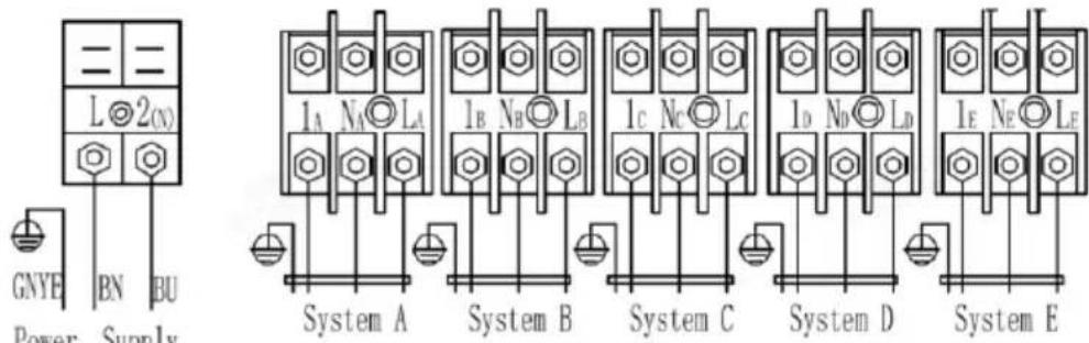
Note: For some models the wires has been connected to the main PCB of indoor unit by manufacturer without terminal block.
INSTALLATION MANUAL---Information for the installer
CABLE WIRES SPECIFICATION
| INVERTER TYPEMODEL capacity (Btu/h) | 9k | 12k | 18k | 24k | 28k | |
| sectional area | ||||||
| Power supply cable | N | 1.5mm^2 | 1.5mm^2 | 2.5mm^2 | 2.5mm^2 | 2.5mm^2 |
| L | 1.5mm^2 | 1.5mm^2 | 2.5mm^2 | 2.5mm^2 | 2.5mm^2 | |
| 1.5mm^2 | 1.5mm^2 | 2.5mm^2 | 2.5mm^2 | 2.5mm^2 | ||
| Connection supply cable | N | 0.75mm^2 | 0.75mm^2 | 0.75mm^2 | 0.75mm^2 | 1.5mm^2 |
| L | 0.75mm^2 | 0.75mm^2 | 0.75mm^2 | 0.75mm^2 | 1.5mm^2 | |
| 1 | 0.75mm^2 | 0.75mm^2 | 0.75mm^2 | 0.75mm^2 | 1.5mm^2 | |
| 0.75mm^2 | 0.75mm^2 | 0.75mm^2 | 0.75mm^2 | 1.5mm^2 | ||
220V Air conditioner (7k\~30k) indoor unit fuse : 50T, 3.15A
110V Air conditioner (7k\~12k) indoor unit fuse : 50T, 3.15A
125V Air conditioner (7k\~12k) indoor unit fuse : 61T, 15A
250V Air conditioner (18k\~24k) indoor unit fuse : 65TS, 25A
MAINTENANCE
| Warning | When cleaning, you must shut down the machine and cut off the power supply for more than 5 minutes.Under no circumstances should the air conditioner be flushed with water.Volatile liquid (e.g. thinner or gasoline) will damage the air conditioner, so only use soft dry cloth or wet cloth dipped with neutral detergent to clean the air conditioner.Pay attention to cleaning the filter screen regularly to avoid dust covering which will affect the filter screen effect. When the operating environment is dusty, the cleaning frequency should be increased appropriately.After removing the filter screen, do not touch the fins of the indoor unit to avoid scratching. |
| Clean the unit | 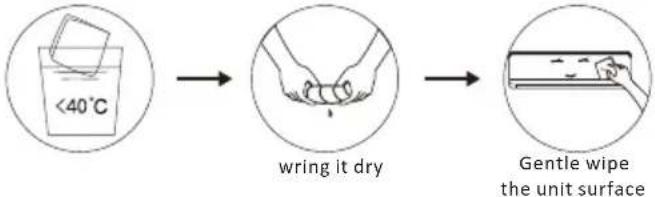 Tip: Wipe frequently to keep air conditioner clean and good appearance . Tip: Wipe frequently to keep air conditioner clean and good appearance . |
| Disassembly and assembly of filter screen | Grasp the raised plastic handle on the filter screen by hand, and then pull the filter screen out in the direction deviating from the unit, so that the upper edge of the filter screen is separated from the unit.The filter can be removed by lifting the filter upwards.When installing the filter screen, first insert the lower end of the filter screen into the corresponding position of the unit, and then squeeze the upper end of the filter screen into the corresponding buckling position of the unit body.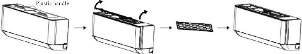 |
| Clean the filter screen | 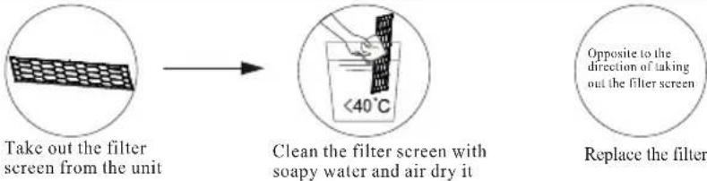 Tip: When you find accumulated dust in the filter screen, please clean the filter screen in time to ensure the clean, healthy and efficient operation inside the air conditioner. Tip: When you find accumulated dust in the filter screen, please clean the filter screen in time to ensure the clean, healthy and efficient operation inside the air conditioner. |
| Cleaning of inner air duct | First, loosen the knob on the middle of louver and bend throughs to take it out.Then, grasp both sides of bottom plate push downwards to take down the bottom plate.Finally, loaded deflector assembly with your thumb and take it out.Wipe the air duct and fan assembly with a clean and wrung wet rag.Clean the removed parts with soapy water and air dry it.After cleaning, restore the removed parts in turn.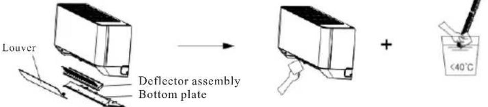 |
| Service and maintenance | When the air conditioner is not in use for a long time, do the following work:Take out the batteries of the remote controller and disconnect the power supply of the air conditioner.When starting to use after long-term shutdown:Clean the unit and filter screen;Check whether there are obstacles at the air inlet and outlet of indoor and outdoor units;Check whether the drain pipe is unobstructed;Install the batteries of the remote controller and check whether the power is on. |
TROUBLESHOOTING
| MALFUNCTION | POSSIBLE CAUSES |
| The appliance does not operate | Power failure/plug pulled out. |
| Damaged indoor/outdoor unit fan motor. | |
| Faulty compressor thermomagnetic circuit breaker. | |
| Faulty protective device or fuses. | |
| Loose connections or plug pulled out. | |
| It sometimes stops operating to protect the appliance. | |
| Voltage higher or lower than the voltage range. | |
| Active TIMER-ON function. | |
| Damaged electronic control board. | |
| Strange odor | Dirty air filter. |
| Noise of running water | Back flow of liquid in the refrigerant circulation. |
| A fine mist comes from the air outlet | This occurs when the air in the room becomes very cold, for example in the “COOLING”or DEHUMIDIFYING/DRY modes. |
| A strange noise can be heard | This noise is made by the expansion or contraction of the front panel due to variations in temperature and does not indicate a problem. |
| Insufficient airflow, either hot or cold | Unsuitable temperature setting. |
| Obstructed air conditioner intakes and outlets. | |
| Dirty air filter. | |
| Fan speed set at minimum. | |
| Other sources of heat in the room. | |
| No refrigerant. | |
| The appliance does not respond to commands | Remote control is not close enough to indoor unit. |
| The batteries of remote control need to be replaced. | |
| Obstacles between remote control and signal receiver in indoor unit. | |
| The display is off | Active LIGHT function. |
| Power failure. | |
| Switch off the air conditioner immediately and cut off the power supply in the event of: | Strange noises during operation. |
| Faulty electronic control board. | |
| Faulty fuses or switches. | |
| Spraying water or objects inside the appliance. | |
| Overheated cables or plugs. | |
| Very strong smells coming from the appliance. |
ERROR SIGNALS ON THE DISPLAY
| In case of error, the display on the indoor unit shown the following error codes: | |||
| Description of the troubleDisplay | Display | Description of the trouble | |
| E1 | Indoor temperature sensor fault | E8 | Outdoor discharge temperature sensor fault |
| E2 | Indoor pipe temperature sensor fault | E9 | Outdoor IPM module fault |
| E3 | Outdoor pipe temperature sensor fault | EA | Outdoor current detect fault |
| E4 | Refrigerant system leakage or fault | EE | Outdoor PCB EEPROM fault |
| E6 | Malfunction of indoor fan motor | EF | Outdoor fan motor fault |
| E7 | Outdoor air temperature sensor fault | EH | Outdoor suction temperature sensor fault |


Like us on Facebook
TCL Electronics Australia Pty Ltd
ABN 83 111 032 896 Telephone: 1300 738 149 service.au@tcl.com www.tcl.com/au