
BV410D-GS02-QM-S - Label printer TOSHIBA - Free user manual and instructions
Find the device manual for free BV410D-GS02-QM-S TOSHIBA in PDF.

| Product Type | Direct Thermal Label Printer |
| Model | BV410D-GS02-QM-S |
| Brand | Toshiba Tec Corporation |
| Resolution | 203 dpi (8 dots/mm) |
| Print Method | Direct Thermal |
| Max Print Speed | 177.8 mm/s (7 in/s) in batch/cut mode |
| Effective Print Width | 108.0 mm (4.25 in) |
| Media Width | 25.4 mm to 118 mm (1.0 to 4.6 in) |
| Max Roll Diameter | 127 mm (5 in); up to 214 mm with optional external media stand |
| Inner Core Diameter | 25.4, 38.1, 42, or 76.2 mm (1.0, 1.5, 1.65, or 3.0 in) |
| Supply Voltage | DC +24V, 2.5A (external AC adapter) |
| Power Consumption | 60 W during printing, 4.4 W standby |
| Dimensions (W x D x H) | 169 x 213 x 173 mm (6.66 x 8.39 x 6.81 in) |
| Weight | 2.0 kg (4.4 lb) |
| Operating Temperature | 5°C to 40°C (41°F to 104°F) |
| Storage Temperature | -20°C to 60°C (-4°F to 140°F) |
| Humidity | 25% to 85% RH (operating), 10% to 90% RH (storage) |
| Standard Interfaces | USB 2.0 Hi-Speed, Ethernet (10BASE-T/100BASE-TX) |
| Optional Interfaces | Serial RS-232C, Wireless LAN (802.11a/b/g/n), Bluetooth 2.1+EDR |
| Supported Barcodes | UPC-A/E, EAN8/13, Code39/93/128, EAN128, NW7, MSI, ITF, POSTNET, RM4SCC, KIX, GS1 Databar, USPS Intelligent Mail |
| Supported 2D Codes | Data Matrix, PDF417, QR Code, Maxi Code, Micro PDF417, Micro QR, GS1 Data Matrix, Aztec Code |
| Print Modes | Batch, Strip (with optional peel-off module), Cut (with optional cutter) |
| Maintenance | Clean print head with ethyl alcohol; wipe platen roller and sensors regularly |
| Safety Certifications | CE, FCC Part 15 Class A, ICES-003, RoHS compliant |
Frequently Asked Questions - BV410D-GS02-QM-S TOSHIBA
User questions about BV410D-GS02-QM-S TOSHIBA
0 question about this device. Answer the ones you know or ask your own.
Ask a new question about this device
Download the instructions for your Label printer in PDF format for free! Find your manual BV410D-GS02-QM-S - TOSHIBA and take your electronic device back in hand. On this page are published all the documents necessary for the use of your device. BV410D-GS02-QM-S by TOSHIBA.
USER MANUAL BV410D-GS02-QM-S TOSHIBA
CE Compliance (for EU only)
This product is labelled with the CE mark in accordance with the provisions of the applicable European Directives, notably the Low Voltage Directive 2014/35/EU, the Electromagnetic Compatibility Directive 2014/30/EU, the RoHS Directive 2011/65/EU, (EU) 2015/863 for this product and the electric accessories.
CE marking is the responsibility of TOSHIBA TEC GERMANY IMAGING SYSTEMS GmbH, Carl-Schurz-Str. 7, 41460 Neuss, Germany, phone +49-(0)-2131-1245-0.
For a copy of the related CE Declaration of Conformity, please contact your dealer or Toshiba Tec Corporation.

WARNING:
This is a Class A product. In a domestic environment, this product may cause radio interference in which case the user may be required to take adequate measures.
FCC Notice
This equipment has been tested and found to comply with the limits for a Class A digital device, pursuant to Part 15 of the FCC Rules. These limits are designed to provide reasonable protection against harmful interference when the equipment is operated in a commercial environment. This equipment generates, uses, and can radiate radio frequency energy and, if not installed and used in accordance with the instruction manual, may cause harmful interference to radio communications. Operations of this equipment in a residential area is likely to cause harmful interference in which case the user will be required to correct the interference at his own expense.
WARNING
Changes or modifications not expressly approved by the party responsible for compliance could void the user's authority to operate the equipment.
(for USA only)
CAN ICES-3 (A) / NMB-3 (A)
This Class A digital apparatus complies with Canadian ICES-003.
(for CANADA only)


California Proposition 65:USA-California only
WARNING:
This product can expose you to chemicals including 1,3-Dichloro-2-propanol, which is/are known to the State of California to cause cancer.
For more information go to www.P65Warnings.ca.gov.
The device is not intended for use in the direct field of view at visual display workplaces.
To avoid incommoding reflections at visual display workplaces this device must not be placed in the direct field of view.
한국 전원 코드
Waste Recycling information for users:

Following information is only for EU-member states:
The use of the crossed-out wheeled bin symbol indicates that this product may not be treated as general household waste.
By ensuring this product is disposed of correctly you will help prevent potential negative consequences for the environment and human health, which could otherwise be caused by inappropriate waste handling of this product. For more detailed information about the take-back and recycling of this product, please contact your supplier where you purchased the product.
Notification (for Turkey)
Following information is only for India:

The use of the symbol indicates that this product may not be treated as household waste. By ensuring this product is disposed of correctly, you will help prevent potential negative consequences for the environment and human health, which could otherwise be caused by inappropriate waste handling of this product.
For more detailed information about the take-back and recycling of this product, please contact your supplier where you purchased the product.
This product including components, consumables, parts and spares complies with the “India E-Waste Rules” and prohibits use of lead, mercury, hexavalent chromium, polybrominated biphenyls or polybrominated diphenyl ethers in concentrations exceeding 0.1% by weight and 0.01% by weight for cadmium, except for the exemption set in the Rule.
This product is designed for commercial usage and is not consumer product.
NOTES:
- This manual may not be copied in whole or in part without prior written permission of Toshiba Tec Corporation.
- The contents of this manual may be changed without notification.
- Please refer to your local authorized service representative with regard to any queries you may have in this manual.
- Windows is a registered trademark of Microsoft Corporation.
Importer (For EU, EFTA)
Toshiba Tec Germany Imaging Systems GmbH
Carl-Schurz-Str. 7, 41460 Neuss, Germany
Importer (For Turkey)
BOER BILISIM SANAYI VE TICARET ANONIM SIRKETI BCP
Yukari Dudullu, Tavukcuyolu Cad. Demirturk Sok No: 8A 34775,
Umraniye-Istanbul, Turkey
Manufacturer:
Toshiba Tec Corporation
1-11-1, Osaki, Shinagawa-ku, Tokyo, 141-8562, Japan
This product is classified as “wireless equipment for stations of low-power data transmissions systems” under the Wireless Telegraphy Act, and does not require a radio transmission license. The law prohibits modification of the interior of this product.
■ Regulatory Information
This product must be installed and used in strict accordance with the manufacturer's instructions as described in the user documentation that comes with the product. This product complies with the following radio frequency and safety standards.
Standards below are certified under the operation with the provided antenna. Do not use this product with other antennas.
□ Europe - EU Declaration of Conformity
Hereby, Toshiba Tec Corporation, declares that the BV410D/BV420D series are in compliance with the essential requirements and other relevant provisions of Directive 2014/53/EU.
USA-Federal Communications Commission (FCC)
NOTE:
This equipment has been tested and found to comply with the limits for a Class A digital device, pursuant to Part 15 of the FCC Rules. These limits are designed to provide reasonable protection against harmful interference when the equipment is operated in a commercial environment. This equipment generates, uses, and can radiate radio frequency energy and, if not installed and used in accordance with the instruction manual, may cause harmful interference to radio communications. Operations of this equipment in a residential area is likely to cause harmful interference in which case the user will be required to correct the interference at his own expense.
CAUTION:
This device complies with Part 15 of the FCC Rules.
Operation is subject to the following two conditions:
(1) this device may not cause harmful interference, and
(2) this device must accept any interference received, including interference that may cause undesired operation.
Any changes or modifications not expressly approved by the grantee of this device could void the user's authority to operate the equipment.
RF EXPOSURE WARNING:
This equipment must be installed and operated in accordance with provided instructions and the antenna(s) used for this transmitter must be installed to provide a separation distance of at least 20 cm from all persons and must not be co-located or operating in conjunction with any other antenna or transmitter. End-users and installers must be provide with antenna installation instructions and transmitter operating conditions for satisfying RF exposure compliance.
Canada - Industry Canada (IC)
This device complies with Canada licence-exempt RSS standard(s).
Operation is subject to the following two conditions:
(1) this device may not cause interference, and
(2) this device must accept any interference, including interference that may cause undesired operation of the device.
Radio Frequency (RF) Exposure Information
The radiated output power of the Wireless Device is below the Industry Canada (IC) radio frequency exposure limits. The Wireless Device should be used in such a manner such that the potential for human contact during normal operation is minimized.
This device has also been evaluated and shown compliant with the IC RF Exposure limits under mobile exposure conditions (antennas are greater than 20cm from a person's body).
■ Approved Countries/Regions for Use for the Devices
This equipment is approved to the radio standard by the specific countries/regions. Please ask Toshiba Tec authorized dealers or service technicians.
■ Precaution for Use
This product communicates with other devices by radio. Depending on the installation location, orientation, environment, etc., its communication performance may deteriorate or devices installed near by may be affected.
Bluetooth ^® and Wireless LAN devices operate within the same radio frequency range and may interfere with one another. If you use Bluetooth ^® and Wireless LAN devices simultaneously, you may occasionally experience a less than optimal network performance or even lose your network connection.
If you should experience any such problem, immediately turn off your Bluetooth ^® or Wireless LAN device.
Keep away from a microwave.
Communication performance may deteriorate or a communication error may occur due to the radio emitted from a microwave.
Do not use the product on a metal table or near a metal object. Communication performance may be deteriorated.
* Bluetooth * is a registered trademark owned by Bluetooth SIG, Inc.
■ Safety Summary
Personal safety in handling or maintaining the equipment is extremely important. Warnings and Cautions necessary for safe handling are included in this manual. All warnings and cautions contained in this manual should be read and understood before handling or maintaining the equipment.
Do not attempt to effect repairs or modifications to this equipment. If a fault occurs that cannot be rectified using the procedures described in this manual, turn off the power, unplug the machine, and then contact your authorized Toshiba Tec Corporation representative for assistance.
■ Meanings of Each Symbol
 | WARNING | This symbol indicates a potentially hazardous situation which, if not avoided, could result in death, serious injury, or serious damage, or fire in the equipment or surrounding objects. |
 | CAUTION | This symbol indicates a potentially hazardous situation which, if not avoided, may result in minor or moderate injury, partial damage to the equipment or surrounding objects, or loss of data. |
 | PROHIBITED This symbol indicates prohibited actions (prohibited items).Specific prohibited contents are drawn inside or near the symbol.(The symbol on the left indicates “no disassembling”.) | |
 | MUST be Performed | This symbol indicates actions which must be performed.Specific instructions are drawn inside or near the symbol.(The symbol on the left indicates “disconnect the power cable plug from the outlet”.) |
Note
Indicates information to which you should pay attention when operating the manual.
WARNING
 | WARNINGThis indicates that there is the risk of death or serious injury if the machine is improperly handled contrary to this indication. | |
 | Any other than the specified AC voltage is prohibited. | Do not use voltages other than the AC voltage specified on the rating plate, as this may cause a fire or an electric shock. |
 | Prohibited | Do not plug in or unplug the power cable with wet hands as this may cause an electric shock. |
 | Prohibited | If the machine share the same electrical outlet with any other appliance that consumes a large amount of power, the voltage will fluctuate widely each time these appliances operate. Be sure to provide an exclusive outlet for the machine as this may cause a fire or an electric shock. |
 | Prohibited | Do not place metal objects or water-filled containers such as flower vases, flower pots or mugs, etc. on the top of the machine. If metal objects or spilled liquid enter the machine, this may cause a fire or an electric shock. |
 | Prohibited | Do not insert or drop metal, flammable or other foreign objects into the machine through the ventilation slits, as this may cause a fire or an electric shock. |
 | Prohibited Do not scratch, damage or modify the power cable. Also, do not place heavy objects on, pull on, or excessively bend the power cable, as this may cause a fire or an electric shock. | |
 | Disconnect the plug. | If the machine is dropped or their cabinet damaged, first turn off the power switch and disconnect the power cable plug from the outlet, and then contact your authorized Toshiba Tec Corporation representative for assistance.Continued use of the machine in that condition may cause a fire or an electric shock. |
 | Disconnect the plug. | Continued use of the machine in an abnormal condition such as when the machine is producing smoke or strange smells may cause a fire or an electric shock.In these cases, immediately turn off the power switch and disconnect the power cable plug from the outlet.Then, contact your authorized Toshiba Tec Corporation representative for assistance. |
 | Disconnect the plug. | If foreign objects (metal fragments, water, liquids) enter the machine, turn off the power switch and disconnect the power cable plug from the outlet, and then contact your authorized Toshiba Tec Corporation representative for assistance.Continued use of the machine in that condition may cause a fire or an electric shock. |
 | Disconnect the plug. | When unplugging the power cable, be sure to hold and pull on the plug.Pulling on the cable may cut or expose the internal wires and cause a fire or an electric shock. |
 | Connect a grounding wire. | Ensure that the equipment is properly grounded.Extension cables should also be grounded.Fire or electric shock could occur on improperly grounded equipment. |
 | No disassembling. | Do not remove covers, repair or modify the machine by yourself.Contact your authorized Toshiba Tec Corporation representative for assistance.You may be injured by high voltage, very hot parts or sharp edges inside the machine. |
 | Prohibited Do not use a spray cleaner containing flammable gas for cleaning this product, as this may cause a fire. | |
 | Prohibited | Care must be taken not to injure yourself with the printer paper cutter. |
CAUTION

CAUTION
This indicates that there is the risk of personal Injury or damage to objects if the machine is improperly handled contrary to this indication.
Precautions
The following precautions will help to ensure that this machine will continue to function correctly.
- Try to avoid locations that have the following adverse conditions:
- Temperatures out of the specification
- Direct sunlight
- High humidity
- Shared power source
- Excessive vibration
- Dust / Gas
- The cover should be cleaned by wiping with a dry cloth or a cloth slightly damped with a mild detergent solution. NEVER USE THINNER OR ANY OTHER VOLATILE SOLVENT on the plastic covers.
• USE ONLY TOSHIBA TEC CORPORATION SPECIFIED paper.
- DO NOT STORE the paper where they might be exposed to direct sunlight, high temperatures, high humidity, dust, or gas.
- Ensure the printer is operated on a level surface.
- When an external power source such an AC adapter is connected to the printer, DO NOT use any device other than the FSP060-RAAK3 AC adapter.
- Any data stored in the memory of the printer could be lost during a printer fault.
- Try to avoid using this equipment on the same power supply as high voltage equipment or equipment likely to cause mains interference.
- Unplug the machine whenever you are working inside it or cleaning it.
- Keep your work environment static free.
- Do not place heavy objects on the top of the machine, as these items may become unbalanced and fall causing injury.
- Do not block the ventilation slits of the machine, as this will cause heat to build up inside the machine and may cause a fire.
- Do not lean against the machine. It may fall on you and could cause injury.
- Unplug the machine when it is not used for a long period of time.
- Place the machine on a stable and level surface.
Request Regarding Maintenance
- Utilize our maintenance services. After purchasing the machine, contact your authorized Toshiba Tec Corporation representative for assistance once a year to have the inside of the machine cleaned.
Dust will build up inside the machine and may cause a fire or a malfunction. Cleaning is particularly effective before humid rainy seasons.
- Our preventive maintenance service performs periodic checks and other work required to maintain the quality and performance of the machine, preventing accidents beforehand.
For details, please consult your authorized Toshiba Tec Corporation representative.
• Using insecticides and other chemicals
Do not expose the machine to insecticides or other volatile solvents. This will cause the cabinet or other parts to deteriorate and may cause the paint to peel.
Notes to Users....1
Precautions for the handling of Wireless Communication Devices 4
Regulatory Information 4
Approved Countries/Regions for Use for the Devices 5
Precaution for Use 5
Safety Precautions 6
Safety Summary 6
Meanings of Each Symbol 6
WARNING 6
CAUTION 8
1. Product Overview ...... 11
Introduction 11
Features 11
Unpacking 11
When purchasing the power cable 12
2. Description of Components .... 14
Front and rear views 14
Interior 15
3. Accessories 16
4. Operation Panel Functions ...... 17
BV410D 17
BV420D 19
5. Printer Setup.... 20
Precautions 20
Setup procedure of the printer 21
6. Connecting the Cables.... 22
7. Connecting the AC Adapter and Power Cable.... 23
8. Turning the Printer On and Off.... 24
How to turn the power on 24
How to turn the power off 24
9. Opening and Closing the Top Cover 25
To open the top cover 25
To close the top cover 25
10. Loading the Media 26
Loading the media roll (label roll and tag roll) 26
Loading the fanfold paper 29
11. Adjusting the Media Sensors .... 30
Feed gap sensor 30
Black mark sensor 30
12. Print mode 31
Batch mode 31
Strip mode (Option) 31
Cut mode (Option) 32
External media stand (Option) 33
13. Maintenance.... 35
Print head 35
Media sensors 35
Platen roller 36
Peel-off module (Option) 36
Media housing 36
How to store and handle the media 37
14. Troubleshooting 38
Troubleshooting 38
Status lamp 39
Removing jammed media 41
15. Printer Specifications 42
Printer 42
Options 44
16. Media Specifications 45
Media 45
■ Introduction
Thank you for purchasing our barcode printer. This Owner's Manual contains valuable information such as the general setup and how to confirm the printer's operation using test prints. Read this carefully to help you to gain maximum performance and life from your printer. Be sure to keep this manual close at hand for daily reference. For further information concerning this manual, contact your Toshiba Tec Corporation representative.
Features
This printer has the following features:
| Interfaces | A USB port and Ethernet support interface are embedded in this printer as standard. Wireless LAN, Bluetooth and serial interface (RS-232C) can also be embedded as an option. |
| Easy to use | The printer mechanism is designed to allow simple operation and easy access to maintenance. |
| Flexible hardware Sharp and clear printing | g can be achieved by an 8-dot/mm (203 dpi)print head (in BV410D-GS02-QM-S and BV420D-GS02-QM-S) at a speed of up to 177.8 mm/sec. (7"/sec.) or an 11.8-dot/mm (300 dpi) print head (in BV410D-TS02-QM-S and BV420D-TS02-QM-S) at a speed of up to 127 mm/sec. (5"/sec.). |
| Full range of options | The following optional devices can also be installed in this printer.Cutter modulePeel-off moduleExternal media standWireless LAN interfaceBluetooth interfaceSerial (RS-232C) interfaceAC adapter cover |
■ Unpacking
1 Unpack the printer.
2 Check that there are no scratches on the printer or any other damage to it.
Note
Toshiba Tec Corporation shall have no liability for any damage or anything similar sustained during transportation.
3 Keep the carton and internal packing materials for future transportation of the printer.
■ When purchasing the power cable
In some countries, the power cable is not provided with this printer. If this is the case, purchase an approved power cable that meets the following standards or contact your authorized Toshiba Tec Corporation representative.
| Country/Region | Agency | Certification mark | Country/Region | Agency | Certification mark | Country/Region | Agency | Certification mark |
| Australia SAA Germany V |  | SEMKKO |  |  | ||||
| Austria OVE Ireland NSA I |  |  | Switzerland | SEV |  | |||
| Belgium CEBEC Italy IMQ |  |  |  | |||||
| Canada CSA |  | Japan METI |  | BSI |  | |||
| Denmark DEMKO |  | Netherlands | KEMA |  | U.S.A. | UL | ||
| Finland | FEI |  | Norway | NEMKO |  | Europe | HAR | |
| France | UTE |  | Spain | AEE Taiwan GNS € |  | |||
| South Africa | SABS |  | ||||||
| Power cable instructions | |||||
1. For use with 100 – 125 Vac mains power supply, select a power cable rated Min. 125V, 10A.2. For use with 200 – 240 Vac mains power supply, select a power cable rated Min. 250V, 10A.3. Select a power cable with the length of 2 m or less.4. The power cable plug connected to the AC adapter must be able to be inserted into an ICE-320-C14 inlet. Refer to the following figure for the shape.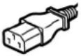 | |||||
| Country/Region N | North America Europe | United Kingdom | Australia South Africa | ||
| Power cableRated (Min.)Type | 125V, 10ASVT | 250VH05VV-F | 250VH05VV-F | 250VAS3191approved,Light or OrdinaryDuty type | 250V, 6AH05VV |
| Conductor size(Min.) | No. 3/18AWG | 3 × 0.75 mm^2 | 3 × 0.75 mm^2 | 3 × 0.75 mm^2 | 3 × 0.75 mm^2 |
| Plug configuration(locally approved type) | 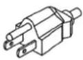 | 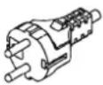 | 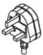 |  | 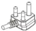 |
| Rated (Min.) | 125V, 10A 250V, 10A | 250V ^*1 | 250V ^*1 | 250V ^*1 | |
*1 At least, 125% of the rated current of the product
2. Description of Components
The name of the components in this section is used in the following chapters.
■ Front and rear views
 | CAUTIONMECHANICAL HAZARDTO avoid injury, be careful not to trap your fingers in the paper slot while opening or closing the top cover. |
![[1] [3]](/content/2026/05/852798/images/77d86d19945b03b56a97e2580a6c77b141e5563034a1d948e269d7dc99a088e8.jpg)
![[4]](/content/2026/05/852798/images/f3f3299d5965e1c122b5c366365ae856426474b3b01ea3d6cc9b3f19ebe3bb44.jpg)
[2]
| No. Part Name No. Part Name | |||
| 1 | [ P O W E R ] | b u | t t o n 3 M e |
| 2 Media outlet 4 Paper slot | |||
d i a v
Note
For the interface section at the rear side, refer to P.22 "6. Connecting the Cables".
Interior
 | ⚠ WARNINGHOT SURFACEYou may get burned.Do not touch the print head or around it immediately after printing.The print head will become very hot during printing. |
![[1] [2] [10] [9] [3] [8] [7] [6] [5] [4] [3] [2] [11] [1]](/content/2026/05/852798/images/d065de3da8b7b64aa3b34da3bc62c513e885c42d76694ad669b64ab9a67437c4.jpg)
| No. | Part Name No. Part Name | ||
| 1 | Top cover 7 Platen roller | ||
| 2 | Lock release portions (left, right) 8 Media guides (left, right) | ||
| 3 | Media roll holder 9 Core holders (left, right) | ||
| 4 | Holder lock lever 10 Media damper (upper) | ||
| 5 | Media damper (lower) 11 Print head | ||
| 6 | M e d i a s e | n s | o r s |
3. Accessories
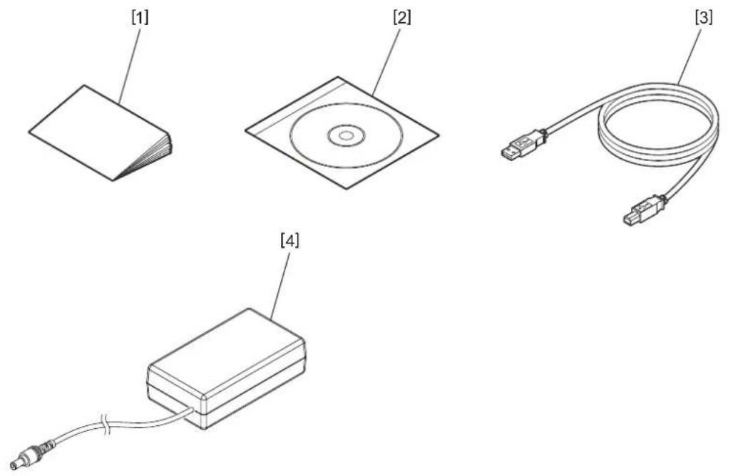
| No. Part Name No. Part Name | |||
| 1 | O w n e r ' s | M a | n u a l 3 U S |
| 2 CD-ROM 4 AC adapter | |||
B c a t
The buttons on the operation panel are used to operate and set the printer.
BV410D
![[1] [2] ONLINE ERROR [3] [4] FEED ▲ [5] RESTART ▼ [6] PAUSE ■](/content/2026/05/852798/images/881cc3971a99efa3b497f74cfac5f00104cd5b325d4cf5e7795ad3a1699a0653.jpg)
| No. | Name Function/Usage | |
| 1 | LCD (Liquid Crystal Display) | Displays the printer status icons, such as the radio intensity and etc.The printer status is indicated in alphanumeric characters or symbols. |
| 2 | ONLINE | Lights when the printer is in the online mode.Blinks when communicating with a host computer. |
| 3 | ERROR lamp | Lights when a communication error occurs, the paper ends or the printer is not operating correctly. |
| 4 | [FEED] button | Feeds one sheet of media by pressing this button while the printer is in the online mode. This is used to move the cursor upward in the operation of the Help screen or the selection screen. |
| 5 | [RESTA | Returns the printer to the online mode by pressing this button after removing the error.Restarts printing by pressing this button while the printer pauses.This is used to reboot the printer by quitting the Help screen or to move the cursor downward in the selection screen. |
| 6 | [PAUSE] button | Pauses printing.Resets the printer when paused or when an error occurs.This is used to fix the items selected in the operation of the Help screen or the selection screen. |
Note
When an error occurs in the printer, the ERROR lamp lights and a message is displayed on the LCD. For details, refer to ☐ P.38 "14. Troubleshooting".
![BV400D-T V1.0 ONLINE PRINTED 000000 IP : 192. XXX. XXX. XXX [1] Till C ≡ [2] [5] [3] [4]](/content/2026/05/852798/images/b15106361475dabc0afb61ecd5ac7ae9940b89da4ca5217d4efdca1f26995ad8.jpg)
| No. | Name Icon Function | /Usage | ||
| 1 | Wireless LAN Indicates | whe  | optional Wireless LAN is installed. The intensity of the Wireless LAN is indicated by 4 levels. | |
| 2 | Link Roaming Indicates | when the option when the optional Wireless LAN is | installed. When the radio wave of the specified access point is lost, another one is searched and is connected automatically. | |
 | Wireless LAN connecting | |||
| 3 | Bluetooth connection | Bluetooth connecting Indicates the Bluetooth connection status when the optional Bluetooth is installed. | ||
 | Bluetooth connectable | |||
| 4 | Bluetooth mode Bluetooth | connection | Indicates during the automatic reconnection mode of Bluetooth. | |
| 5 | Data reception Data transm [GBAS] | on/ reception | Indicates the data transmission status. | |
BV420D
![[1] [2] ONLINE POWER FEED PAUSE [3] [4] [5]](/content/2026/05/852798/images/b2360bd4446df605f7c9272288b4bd5bf42b3e499a60b108a94d34666a925c72.jpg)
| No. | Name Function/Usage | |
| 1 | POWER lamp Lights when the power is turned on. | |
| 2 | O N L I N E | Lights when the printer is in the online mode.Blinks when communicating with a host computer. |
| 3 | ERROR lamp | Lights when a communication error occurs, the paper ends or the printer is not operating correctly. |
| 4 | [FEED] button | Feeds one sheet of media by pressing this button while the printer is in the online mode. |
| 5 | [PAUSE] button | Pauses printing.Resets the printer when paused or when an error occurs. |
Note
When the ERROR lamp lights, an error has occurred in the printer. For details, refer to ☐ P.38 "14. Troubleshooting".
This chapter explains the procedures necessary to set up the printer prior to its operation.
WARNING
Avoid using the printer in the locations where it is subjected to intense light (e.g.: direct sunlight or desk light). Such light may affect the sensors of the printer, causing malfunctions.
Precautions
To insure the best operating environment, as well as to assure the safety of the operator and the printer, be sure to observe the following precautions.
- Operate the printer on a stable and level surface in a location free from excessive humidity, high temperature, dust, vibration and direct sunlight.
- Keep the work environment static free. Static discharges can cause damage to delicate internal components.
- Make sure that the printer is connected to a clean AC power source and that no other high voltage devices that may cause line noise interference are connected to the same power source.
- Ensure that the printer is connected only to an AC power source that has a proper ground (earth) connection.
- Do not operate the printer with the cover open. Be careful not to allow your fingers or any articles of clothing to get caught in any of the moving parts of the printer.
- Before working on the inside of the printer or cleaning it, be sure to turn off the power of the printer and remove the AC adapter from it.
- For best results and a longer printer life, use only Toshiba Tec Corporation recommended media. (Refer to the Supply Manual.)
- Store the media in accordance with “How to store and handle the media” in this manual.
- This printer mechanism contains high voltage components. Therefore, you should never remove any of the covers of the printer as you may get an electric shock.
Additionally, the printer contains many delicate components. They may be damaged if accessed by unauthorized personnel. - Clean the outside of the printer with a clean dry cloth or a clean cloth slightly damped with a mild detergent solution.
- The print head and its peripherals will become very hot during printing. You may get burnt if you touch it in such a condition. Therefore, wait until the printer has cooled down sufficiently before cleaning. Use only the Toshiba Tec Corporation recommended print head cleaner to clean the print head.
- Do not turn off the printer or remove the power plug while printing or while any lamp is blinking.
- The printer shall be installed near the socket outlet and shall be set so that the power plug can be removed from the socket outlet easily.
- The power plug should be removed from the socket outlet once a year at least and cleaned around the prongs. Accumulating dust and dirt could cause a fire due to the heat released by electrical leakage.
- When the printer will not be used for a long time, pull the lock release lever toward you to unlock the top cover so that no pressure is applied to the label.
■ Setup procedure of the printer
This section explains the procedures necessary to set up the printer properly.
CAUTION
- To make a communication with a host computer, an RS-232C, Ethernet or USB cable is required.
- RS-232C cable: 9 pins (Do not use a null modem cable.)
- Ethernet cable: 10/100 base
- USB cable: V2.0 (Hi-Speed)
- The use of a Windows driver will enable printing from Windows applications.
The printer can also be controlled with its own programming commands. For details, contact your Toshiba Tec representative.
1 Unpack the printer and its accessories from the carton.
2 Place the printer in the location where it is used.
To correctly use and install the printer, see the co-packed "Safety Precautions".
3 Check that the printer is turned off.
Refer to 📄 P.24 "8. Turning the Printer On and Off".
4 Connect the printer to the host computer or network using an RS-232C, Ethernet or USB cable.
Refer to ☐ P.22 "6. Connecting the Cables".
5 Connect the AC adapter to the printer and plug the power cable into a properly grounded outlet.
Refer to ☐ P.23 "7. Connecting the AC Adapter and Power Cable".
6 Load the media.
Refer to P.26 "10. Loading the Media".
7 Adjust the position of the media sensors to match the media to be used.
Refer to 📄 P.30 "11. Adjusting the Media Sensors".
8 Install the printer driver in the host computer.
Refer to "Printer Driver" in the CD-ROM.
9 Turn the power on.
Refer to ☐ P.24 "8. Turning the Printer On and Off".
This chapter explains on how to connect the communication cables to the printer from a host computer or other devices. Three types of cables can be used in this printer.
CAUTION
- Be sure to connect the serial cable while the printer and the host computer are turned off.
- If an attempt is made to connect the cable while the printer and the host computer are turned on, this may cause damage, an electric shock or a short circuit.
![[1] [2] [3] [4] [5]](/content/2026/05/852798/images/5b854f659e9986d58f7fd0dfa316a9ba0ef491a2ea636fbe2af17182d323c2c8.jpg)
| No. | Part Name Usage | |
| 1 | Power jack This is used to connect the AC adapter. | |
| 2 | USB interface for connecting a host computer | This is used to connect one of the USB ports of a host computer with a USB cable.Use a USB cable which has a type B plug attached to one of its sides. |
| 3 | USB interface for connecting a USB memory | This is used to connect another device with a USB cable.e.g. the firmware downloading, the flash ROM expansion by a USB memory etc. and not for user. |
| 4 | Ethernet interface This is used to connect a network with | an Ethernet cable. In addition, direct connection to the Ethernet port of a host computer is possible.NoteBe sure to use an Ethernet cable complying with the standard.10BASE-T: Category 3 or greater100BASE-TX: Category 5 or greaterCable length: Up to 100 m segment lengthIf a communication error caused by radio wave interference on the cable has occurred, use a shield cable (STP). |
| 5 | Serial interface (RS-232C)(Option) | This is used to connect one of the COM ports of a host computer with a serial cable. |
1 Plug the power cable [1] into the AC adapter [2].
![[1] [2]](/content/2026/05/852798/images/fa756f6999ad20da83da71dbddabfecdbce6c756f0fe3da90d136d5096d894df.jpg)
Note
If a power cord is not provided with this printer, please purchase the correct one referring to ☐ P.12 "When purchasing the power cable".
2 Plug the AC adapter connector [3] into the power jack [4] at the rear side of the printer.
![[3] [4]](/content/2026/05/852798/images/c92dd06ac5879558d202b9a3e8f6470a801575194632b6cdd5f6ba767b7e325d.jpg)
3 Plug the other end of the power cable into a grounded outlet.
CAUTION
- Press the [POWER] button of the printer to turn it on or off.
Do not plug in or unplug the power cable when you are turning the printer on or off as this may cause a fire, an electric shock or damage to the printer. - Do not turn the power off during printing as this may cause a media jam or damage to the printer.
- Do not turn the power off while the ONLINE lamp is blinking as this may cause loss or corruption of the data being downloaded.
■ How to turn the power on
Note
If the printer is connected to a host computer, it is recommended to turn the printer on first and then the host computer.
1 While the printer is turned off, press the [POWER] button for a few seconds.
2 The LCD on the control panel lights. If the printer is connected to a host computer, the ONLINE lamp lights.
1 While the printer is turned off, press the [POWER] button for a few seconds.
2 The POWER lamp on the control panel lights. If the printer is connected to a host computer, the ONLINE lamp lights.
Note
- Approx. 30 seconds will be required to complete the loading of Open Type fonts after the power is turned on. The ONLINE lamp starts blinking (interval: 0.5 sec.) after 10 seconds have passed after the power has come on. When the loading of Open Type fonts is completed, the ONLINE lamp status is changed to lit. While the ONLINE lamp is blinking, print data can be received; however, printing of files including Open Type fonts is not possible.
- When the ERROR lamp lights, an error has occurred in the printer. For details, refer to 📄 P.38 "14. Troubleshooting".
■ How to turn the power off
Note
If the printer is connected to a host computer, it is recommended to turn the host computer off first and then the printer.
1 If the printer is connected to a host computer, check that the ONLINE lamp on the control panel is lighting (not blinking).
2 Press the [POWER] button for a while. The LCD will go out and the printer will be turned off. If the printer is connected to a host computer, check that the ONLINE lamp on the control panel has gone out.
1 Check that the ONLINE lamp on the control panel is lighting (not blinking).
2 Press the [POWER] button for a while. All the lamps will go out and the printer will be turned off. If the printer is connected to a host computer, check that the ONLINE lamp on the control panel has gone out.
9. Opening and Closing the Top Cover
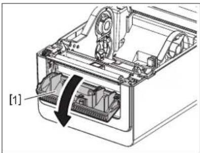
■ To open the top cover
While pulling the lock release part [1], open the top cover [2].
![[1] [2] [1]](/content/2026/05/852798/images/233806fbbb547c8c3459f2f99f90f9700b2b9f8c3c8ad4bf28a2298724291de3.jpg)
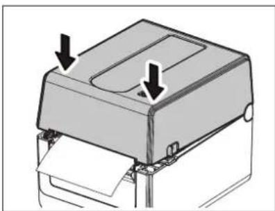
■ To close the top cover
Close the top cover.
natural_image
Diagram of a printer or printer with two arrows pointing to the cover (no text or symbols present)Note
Be sure to close the top cover completely. Otherwise, this may affect the print quality.
10. Loading the Media
This chapter explains how to load the media in the printer. This printer is intended for printing the media roll (label roll and tag roll) and fanfold paper. Use Toshiba Tec Corporation approved media.
WARNING
Do not touch the print head or around it immediately after printing.
The print head will become very hot during printing. You may get burnt if you touch it in such a condition.
CAUTION
• To avoid injury, be careful not to trap your fingers in the paper slot while opening or closing the top cover.
• Do not touch the print head.
Otherwise, some dots may be damaged due to static electricity or other print quality problems.
■ Loading the media roll (label roll and tag roll)
1 Open the top cover.
For details, refer to 📄 P.25 "9. Opening and Closing the Top Cover".
2 While holding the holder lock lever [1], slide the media holder [2] toward the exterior.
![[2] [1]](/content/2026/05/852798/images/5472f85356d7b81cf255149916c43c817844f221cb20d7693879a390af6f101f.jpg)
Note
- Be sure to perform calibration of the media sensors whenever you change the media type. For details, refer to "BV400 Series Key Operation Specification" in the CD-ROM.
• The available media size to be set in the printer is as below.
- Roll diameter: Max. 127 mm (5")
- Inner core diameter: 25.4 mm (1"), 38.1 mm (1.5") or 42 mm (1.65")
- If the roll diameter exceeds 127 mm (5") and the inner core diameter is 76.2 mm (3"), the External media stand (option) is required.
For details, refer to ☐ P.33 "External media stand (Option)".
- The size of the core holder in the media roll holder [1] is set to 38.1 mm (1.5") and 42 mm (1.65") at the time of factory shipment. When a media roll whose inner core diameter is 25.4 mm (1") is used, remove the core holder [2], turn it over and put it into the frame of the printer as shown below.
![[1] [2] [2]](/content/2026/05/852798/images/5d62c9066d528d4375458bf747df15b03dbed2aaf0e31168c77f0deffc2c9398.jpg)
- Printing can be performed with both an outside wound [1] and an inside wound [2] media roll. (Refer to the figure below.) Place the media roll so that its printing surface comes upward.
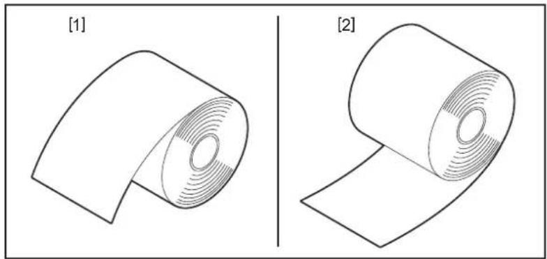
natural_image
Two 3D diagrams showing a rolled object with concentric ridges, labeled [1] and [2], no text or symbols present.2 Place the media roll.
Set the media roll [1] between the media roll holders [2] while its printing surface comes upward.
![[1] [2] [3] [4]](/content/2026/05/852798/images/ce5ee606754484b888a2d57b73317739981a07b3bae9a3986000a4154ad91e99.jpg)
Note
When placing the media roll, be careful not to let it be folded by coming into contact with the media damper (upper) [3] and the media damper (lower) [4] attached to the top cover and the printer.
4 Align the media guides [1] to the media roll width.
While holding the holder lock lever [2], slide the media holder [3] to fix the media roll securely.
![[1] [3] [2]](/content/2026/05/852798/images/ceda3a4158c0e6cb2968f80ca285e8369a523b7c57f7cdc1ace5cf22467567ba.jpg)
Note
- Check that the printer printing surface has come upward.
• Cut the edge of the media with scissors.
![[1] [2] [3] [1] [2] [3]](/content/2026/05/852798/images/8724417b1f90392b8251e2cd135ceb910d65ea5a9ff1cf6136022077f0f19e7c.jpg)
[1] Feed gap sensor
[2] Platen roller
[3] Black mark sensor
5 Load the media.
Pass the media through the media guides [1] and pull it until it reaches the front of the printer.
![[1] [1]](/content/2026/05/852798/images/ae02cd05408b7aeec44fa5b8ca5be4ab351222ade7d865505be74f7c7a27f09d.jpg)
Note
Do not squeeze the media too much with the media guides. Otherwise, the media will bend and this may cause jamming or misfeeding.
6 Adjust the media sensors.
For details, refer to ☐ P.30 "11. Adjusting the Media Sensors".
7 Close the top cover.
For details, refer to P.25 "9. Opening and Closing the Top Cover".
Note
Be sure to close the top cover completely. Otherwise, this may affect the print quality.
8 Press the [FEED] button.
Check that the media is fed correctly.
■ Loading the fanfold paper
Note
- Set the fanfold paper while its printing surface comes upward.
- Place the stack of fanfold paper parallel to the paper slot.
- Check that the interface cable and the power cable do not interfere with the feeding of the fanfold paper.
1 Place the stack of fanfold paper [1] at the rear side of the printer and insert its leading edge into the paper slot [2].
![[1] [2]](/content/2026/05/852798/images/f8447f518347ddfd5cce607a1244949ab394a71e59ef6c73d428e8f341ab6d7d.jpg)
2 Open the top cover.
For details, refer to ☐ P.25 "9. Opening and Closing the Top Cover".
3 Pass the media through the media guides [1] and pull it until it reaches the front of the printer.
![[1] [1]](/content/2026/05/852798/images/6ec7a7182b264379edc04b4d2fdc864db29b56a1077f2c5641a48418a0cd7a8c.jpg)
Note
Do not squeeze the media too much with the media guides. Otherwise, the media will bend and this may cause jamming or misfeeding.
4 Close the top cover. For details, refer to 📋 P.25 "9. Opening and Closing the Top Cover".
11. Adjusting the Media Sensors
The two types of media sensors are equipped in this printer as below.
Feed gap sensor (transmissive): Detects the length between the labels.
Black mark sensor (reflective): Detects the black marks printed on the back side of the media.
Note
- When the media is changed to another one, it is necessary to adjust the sensitivity of these two sensors.
- Otherwise, printed black marks are not detected and an error will occur as a result.
■ Feed gap sensor
- The position [1] of the feed gap sensor is fixed. Align the protrusion of the black mark sensor [2] to the position as shown in the figure below.
- Be sure to perform calibration of the media sensors whenever you change the media type. For details, refer to “BV400 Series Key Operation Specification” in the CD-ROM.
![[1] 6.27mm](/content/2026/05/852798/images/c601b26a7cde78a17cd6f9bbf5f1ea50da4f4fca5473f3f41cc06edc62e3972b.jpg)
![[2]](/content/2026/05/852798/images/c6fa8da02a3fb52ab977f6cb9427ab60bc1d18a3af085e4a2ee18b89ede90433.jpg)
Note
The feed gap sensor is positioned 6.27 mm right from the media center.
Black mark sensor
1 Slide the black mark sensor [2] toward the right or left to align it to the center of the black mark of the media.
natural_image
Technical diagram of a mechanical assembly with exploded view and close-up view (no text or symbols)![[2]](/content/2026/05/852798/images/8f8d69a3c5224c2857cd527e1805ac45efba2dc87910830c78c3923abb320b09.jpg)
Tip
The black mark sensor is movable over the range of the media width [3].
![[3]](/content/2026/05/852798/images/48ef169b1a9f34fc6bd68a5cab081e378d8e0dd7c332c00d69d63393c5ee49a5.jpg)
2 Adjust the sensitivity of the black mark sensor.
For details, refer to "BV400 Series Key Operation Specification" in the CD-ROM.
12. Print mode
There are four print modes available for this printer.
Batch mode
In the batch mode, the media is continuously printed and fed until the number of prints specified in the issue command has been printed.
Note
To separate the printed media from the printer in the batch mode, tear the media off at the media outlet with your hands. (When the optional peel-off module is installed, tear the media off outside of the strip plate.) If you have torn the media off at the print head mistakenly, be sure to feed one label (10 mm or more) by pressing the [FEED] button prior to the next print. Otherwise, this may cause a media jam.
Strip mode (Option)
When the optional peel-off module is installed and printing is performed in the strip mode, labels are automatically removed from the backing paper as each label is printed.
Note
When you print labels without removing them from the backing paper, it is not necessary to pass the media through the media slot.
1 Place the media.
For details, refer to ☐ P.26 "10. Loading the Media".
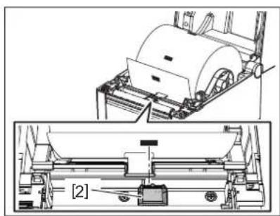
2 Open the peel-off module [1].
natural_image
Technical diagram of a computer printer internal structure showing internal components and a labeled component [1] (no text or symbols beyond label)3 Remove enough labels [2] from the leading edge of the media so as only the backing paper portion can be created.
![[2]](/content/2026/05/852798/images/a7e79c899cc84fd2b1d925b2789188fc18a5e6867e4a5f9e142a2d84f223e5d2.jpg)
4 Pass through the backing paper [3] between the strip feed roller [4] and the peel-off bar [5].
![[3] [4] [5]](/content/2026/05/852798/images/7a3fb7ed2676b493f7d9e5e3a48622194880ce6871dc02f46885d55db7da2f0f.jpg)
5 Close the peel-off module [2] while slightly pulling the media toward you so that its backing paper [1] is not loosened.
![[2] [1]](/content/2026/05/852798/images/8264485832eac7f2b2b9e0bc3ee4227f431923f24307acb76586d54ce126efc8.jpg)
6 Close the top cover.
For details, refer to ☐ P.25 "9. Opening and Closing the Top Cover".
■ Cut mode (Option)
When the optional cutter module is installed, the media can be automatically cut.
WARNING
HAZARDOUS MOVING PARTS KEEP FINGERS AND OTHER BODY PARTS AWAY
The cutter is sharp, so care must be taken not to injure yourself when handling the cutter.
CAUTION
- Be sure to cut only the backing paper of the label.
Cutting labels will cause glue to stick to the cutter blades which may affect the cutter quality and shorten its life. - Use of tag paper with a thickness exceeding the maximum specified value may affect the cutter life.
1 Place the media.
For details, refer to 📄 P.26 "10. Loading the Media".
2 Load the media.
Set the media between the media guides [1] and then pass it through the media outlet [2] of the cutter module.
![[2] [1] [1]](/content/2026/05/852798/images/9e8852ea962e3cb4a6efdf80767e1ea0ebffe5ad873548c16f68904e5b3b3e3f.jpg)
Note
Do not squeeze the media too much with the media guides. Otherwise, the media will bend and this may cause jamming or misfeeding.
3 Close the top cover.
For details, refer to ☐ P.25 "9. Opening and Closing the Top Cover".
■ External media stand (Option)
If the roll diameter exceeds 127 mm (5") and the inner core diameter is 76.2 mm (3"), the External media stand (option) is required.
1 Install the External media stand [1] in the foot at the bottom of the printer.
![TOSHIBA BV410D-GS02-QM-S - Install the External media stand [1] in the foot at the bottom of the printer. - 1](/content/2026/05/852798/images/f16a5384862f5fd6aef9a519fcc3d823bf741010b857c5c46a9e55b7134df684.jpg)
natural_image
Mechanical assembly diagram showing a bracket with internal components and a box-like housing, labeled [1] (no text or symbols on the diagram itself)2 Insert the media shaft [2] into the core of the media roll [3].
![[3] [2]](/content/2026/05/852798/images/9ac4d524e54d64a8f35649fbea49f09925ac3c273f0501fa5227ab60fbedae3f.jpg)
3 Insert the media shaft [3] into the slot [4] on the External media stand.
![[3] [4]](/content/2026/05/852798/images/f8d8866ef0789dba073afc37ee74d834d7148783dc8b26145371f6d1d487db18.jpg)
4 Insert the leading edge of the media into the paper slot [5] of the printer.
![TOSHIBA BV410D-GS02-QM-S - Insert the leading edge of the media into the paper slot [5] of the printer. - 1](/content/2026/05/852798/images/107aeac902d54d561dadf55d6a485833ffe22aebba81c336f70e48e7a8d0d2be.jpg)
natural_image
Technical diagram of a mechanical assembly with labeled component [5], no readable text or symbols present5 Open the top cover.
For details, refer to ☐ P.25 "9. Opening and Closing the Top Cover".
6 Pass the media through the media guides [1] and pull it until it reaches the front of the printer.
![[1] [1]](/content/2026/05/852798/images/7c9338f34be233913b29137066025ce1fe6351838f42245b9ad0a400ced2e303.jpg)
Note
Do not squeeze the media too much with the media guides. Otherwise, the media will bend and this may cause jamming or misfeeding.
7 Close the top cover.
For details, refer to 📄 P.25 "9. Opening and Closing the Top Cover".
13. Maintenance
This chapter explains the routine maintenance procedures.
To ensure the continuous high quality operation of your printer, regularly perform the maintenance routines or every time when the media is changed.
When the printer is intensively used (high throughout), perform the maintenance on a daily basis. When the printer is not intensively used, perform these maintenance on a weekly basis.
WARNING
- Before cleaning the printer and its inside, be sure to turn off the power of the printer and unplug the power plug from the outlet for safety.
- To avoid injury, be careful not to trap your fingers in the paper slot while opening or closing the top cover. You may injure yourself.
- The print head will become very hot during printing. Therefore, do not touch the print head or its vicinity immediately after printing. You may get burnt if you touch it in such a condition.
- Do not pour water directly onto the printer. This may cause damage, an electric shock or a fire.
CAUTION
- Do not allow any hard objects to touch the print head or platen roller. This may cause damage to them.
- Do not use any volatile solvents including thinner and benzene. This may cause discoloration of the cover, print failure or printer damage.
- Do not touch the print head with your bare hands. This may cause static electricity and thus may damage the print head.
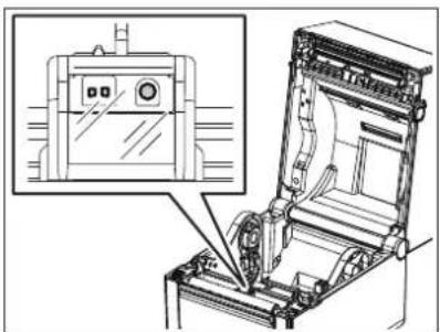
Print head
1 Turn the power off and open the top cover.
2 Clean the print head with a print head cleaner, cotton swab or soft cloth slightly moistened with ethyl alcohol.
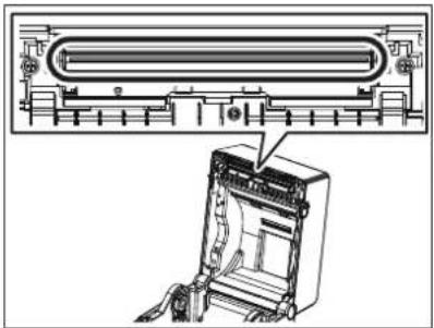
natural_image
Technical line drawing of a device with a panel and internal components, showing no text or symbols.Media sensors
1 Turn the power off and open the top cover.
2 Wipe the media sensors with a soft cloth or a cotton swab slightly moistened with absolute (pure) ethyl alcohol.
To remove dust or paper particles, wipe the media sensors with a dry soft cloth.
natural_image
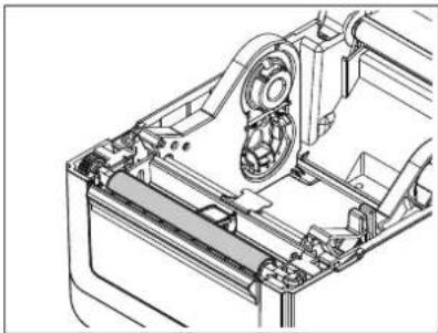
Technical line drawing of an open industrial machine with a close-up inset showing internal components (no text or symbols)■ Platen roller
1 Turn the power off and open the top cover.
2 Wipe the platen roller with a soft cloth slightly moistened with absolute (pure) ethyl alcohol.
natural_image
Technical line drawing of a mechanical assembly with gears and housing (no text or symbols)■ Peel-off module (Option)
1 Turn the power off and open the peel-off module.
2 Clean the surface of the roller [1], the edges [2] of the peel-off module cover and the ribs [3] of the backing paper transport guide with a dry soft cloth.
![[3] [1] [3] [2] [2]](/content/2026/05/852798/images/c2fc3d6813c4693a1ffe6e65a6e19a3a2645172340939f98d1b5cac4e7c30f32.jpg)
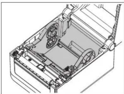
■ Media housing
1 Turn the power off and ope the top cover.
2 Wipe the media housing with a dry soft cloth. If dirt still adheres, wipe it off with a soft cloth slightly moistened with mild detergent solution.
natural_image
Technical line drawing of a mechanical device with internal components and mounting brackets (no text or symbols)■ How to store and handle the media
CAUTION
Be sure to carefully review and understand the Supply Manual. Use only media which meets the specified requirements. Use of non-specified media may shorten the head life and result in problems concerning barcode readability or print quality. All media should be handled with care to avoid any damage to the media or the printer. Read the guidelines in this section carefully.
- Do not store media for longer than the manufacturer's recommended shelf life.
- Store the media on the flat end. Do not store them on the curved sides as this might flatten that side causing an erratic media advance and poor print quality.
- Store the media in plastic bags and always reseal after opening. Unprotected media can get dirty and the extra abrasion from the dust and dirt particles will shorten the print head life.
- Store the media in a cool, dry place. Avoid areas where they would be exposed to direct sunlight, high temperatures, high humidity, dust or gas.
- The thermal paper used for direct thermal printing must not have specifications which exceed Na^+ 800 ppm, K^+ 250 ppm and Cl 500 ppm.
- Some ink used on pre-printed media may contain ingredients which shorten the print head's product life. Do not use labels pre-printed with ink which contain hard substances such as carbonic calcium (CaCO3) and kaolin (Al2O3, 2SiO2, 2H_2O) .
For further information, contact your local distributor or your media manufacturer.
WARNING
If a problem cannot be solved by taking the actions described in this chapter, do not attempt to repair the printer. Turn off and unplug the printer. Then contact an authorized Toshiba Tec representative for assistance.
Troubleshooting
| Symptom Cause Solutions | ||
| The POWER lamp of the printer does not light when the [POWER] button is pressed. | The power cable is not connected to the AC adapter. | Unplug the power cable from the AC outlet. Connect the power cable to the AC adapter and plug it into the AC outlet.P.23 “7. Connecting the AC Adapter and Power Cable” |
| There is a power failure or the power is not being supplied to the AC outlet. | Check the AC outlet with a power cable from another electric appliance.If the power is not being supplied, ask your electrician or electricity supplier. | |
| The fuse of the building has blown or the circuit breaker has tripped. | Check the fuse or the circuit breaker. | |
| The AC adapter connector is disconnected from the power jack. | Unplug the power cable from the AC outlet. Connect the AC adapter connector to the power jack and plug the power cable to the AC outlet.P.23 “7. Connecting the AC Adapter and Power Cable” | |
| Media is not issued. The media is not loaded correctly. Reload the media correctly. | ||
| Nothing is printed. Even if the direct thermal mode is selected, the direct thermal media is not loaded. | Load a direct thermal media.P.26 “10. Loading the Media” | |
| Poor printing Toshiba Tec Corporation approved media is not used. | Replace the media with the approved one. | |
| Missing dots The print head is dirty. Clean the print head. | P.35 “13. Maintenance” | |
| Media jamming occurs immediately after printing has started. | If the printer is left for a long time without any printing being performed, media jamming may occur between the label and the platen roller. | When the printer will not be used for a long time, pull the lock release lever toward you to unlock the top cover so that no pressure is applied to the label. |
| Symptom | Cause | Solutions |
| Barcodes or 2D codes are not readable correctly. | This symptom might happen depending on paper characteristics. | Increase the module size.Select a lower printing speed.Change the barcode print orientation for the ladder barcode to the picket fence barcode (rotate 90 degrees).Check the scanner settings. |
| Labels are not correctly separated from the backing paper. (When the optional peel-off module is installed) | Toshiba Tec Corporation approved media is not used. | Replace the media with the approved one. |
| The media is not loaded correctly. Reload the media correctly.P.26 “10. Loading the Media” | ||
| The peel-off module opens during printing in the strip mode. (When the optional peel-off module is installed) | The backing paper is loaded in a loose state. | Reload the backing paper correctly.P.31 “12. Print mode” |
| The media is not cut cleanly. (When the optional cutter module is installed) | The cutter blade has reached the end of its useful life. | Turn off the printer and ask your Toshiba Tec representative to replace the cutter module. |
| A wireless LAN communication error occurs immediately after the printer is turned on. | It will take approx. 10 seconds to enable wireless LAN communication while the ONLINE lamp is being lit. | Turn on the printer. Wait at least 10 seconds after the ONLINE lamp has lit to start the communication. |
Status lamp
LED lamps will light (ON) or blink corresponding to the printer status.
BV410D
| LCD message | LED | Printer status | ||||
| ONLINE ERROR | ||||||
| ONLINE ON OFF Normal | - Online mode | |||||
| Blink OFF Normal | - Online mode (communicating) | |||||
| PAUSE OFF OFF Printing | is temporarily stopped (paused). | |||||
| HEAD OPEN OFF OFF The top cover is opened in the online mode. | ||||||
| OFF ON | Printing or media feeding is attempted while the top cover is opened. | |||||
| COMMS ERROR | OFF | ON | A communication error has occurred. (Only when the RS-232C is used) | |||
| PAPER JAM OFF ON 1. | Media jamming has occurred. | |||||
| CUTTER ERROR | OFF | ON | Media jamming has occurred in the cutter module. (Only when the optional cutter module is installed) | |||
| NO PAPER | OFF ON | 1. No media is left. | ||||
| HEAD ERROR | OFF ON | There is a problem in the print head. | ||||
| EXCESS HEAD TEMP OFF ON The print head is too hot. | ||||||
| MEMORY WRITE ERR. | OFF ON | An error has occurred during writing into the flash ROM. | ||||
| FORMAT ERROR OFF ON An error has occurred during initialization of the flash ROM. | ||||||
| MEMORY FULL | OFF | ON | Saving has failed due to the flash ROM having insufficient blank space. | |||
| SYNTAX ERROR | OFF | ON | An improper command such as a print command has been received while the firmware is being upgraded in the download mode. | |||
| SYSTEM ERROR | OFF | ON | When any abnormal operations as below are performed, a system error occurs.(a) Command fetch from an odd address.(b) Access to the word data from a place other than the boundary of the word data.(c) Access to the long word data from a place other than the boundary of the long word data.(d) Access to the area of 80000000H to FFFFFFFH in the logic space in the user system mode.(e) Undefined command placed in other than the delay slot has been decoded.(f) Undefined command in the delay slot has been decoded.(g) Command to rewrite the delay slot has been decoded. | |||
BV420D
| LED | Printer status | ||
| POWER ONLINE ERROR | |||
| ON ON OFF Normal - Online mode | |||
| ON Blink OFF Normal - Online mode (communicating) | |||
| ON OFF OFF 1. The top cover is opened in the online mode. | |||
| 2. Printing is temporarily stopped (paused). | |||
| ON | OFF | ON | 1. A communication error has occurred. (Only when the RS-232C is used) |
| 2-1. Media jamming has occurred. | |||
| 2-2. The media is not loaded correctly. | |||
| 2-3. The media sensors differing from the media to be used are selected. | |||
| 2-4. The black mark sensor is not correctly aligned to the black marks on the media. | |||
| 2-5. The size of the loaded media differs from that for the specified paper size. | |||
| 2-6. The media sensor level is not suitable for the actual media. | |||
| 2-7. The gap of the pre-printed label cannot be detected. | |||
| 3. Media jamming has occurred in the cutter unit. | |||
| 4. No media is left. | |||
| 5. Printing or media feeding is attempted while the top cover is opened. | |||
| 6. There is a problem in the print head. | |||
| 7. The temperature of the print head has exceeded the upper limit. | |||
| 8. An error has occurred during writing into the flash ROM. | |||
| 9. An error has occurred during initialization of the flash ROM. | |||
| 10. Saving has failed due to the flash ROM having insufficient blank space. | |||
| ON OFF | ON 11. An imp | proper command | and such as a print command has been receivedwhile the firmware is being upgraded in the download mode. |
| 12. When any abnormal operations as below are performed, a system error occurs.(a) Command fetch from an odd address.(b) Access to the word data from a place other than the boundary of the word data.(c) Access to the long word data from a place other than the boundary of the long word data.(d) Access to the area of 80000000H to FFFFFFFFH in the logic space in the user system mode.(e) Undefined command placed in other than the delay slot has been decoded.(f) Undefined command in the delay slot has been decoded.(g) Command to rewrite the delay slot has been decoded. | |||
■ Removing jammed media
CAUTION
Do not use any tool that may damage the print head.
When media jamming occurs, please remove jammed media from the printer as following procedure.
1 Turn the power off.
2 Open the top cover and remove the media roll.
3 Remove the jammed media from the printer. DO NOT USE any sharp implements or tools as these could damage the printer.
4 Clean the print head and platen, then remove any further dust or foreign substances.
5 Load the media again, and close the top cover.
This chapter describes the printer specifications.
Printer
The following table shows the printer specifications.
| Item BV410D-GS02-QM-S / BV420D-GS02-QM-S | ||
| Supply voltage DC +24V, 2.5A (External AC adapter) | ||
| Power consumption | ||
| During a print job 60 W | ||
| During standby 4.4 W (without options) | ||
| Operating temperature range 5°C to 40°C (41°F to 104°F) | ||
| Storage temperature range -20°C to 60°C (-4°F to 140°F) | ||
| Relative humidity 25% to 85% RH (no condensation) | ||
| Humidity for storage 10% to 90% RH (no condensation) | ||
| Resolution 203 dpi (8-dot/mm) | ||
| Printing method Direct thermal | ||
| Issue mode Batch, Strip (option), Cut (option) | ||
| Printing speed | ||
| In the batch/cut mode | 50.8 mm/sec. (2"/sec.), 76.2 mm/sec. (3"/sec.), 101.6 mm/sec. (4"/sec.), 127 mm/sec. (5"/sec.), 152.4 mm/sec. (6"/sec.), 177.8 mm/sec. (7"/sec.) | |
| In the strip mode | 50.8 mm/sec. (2"/sec.), 76.2 mm/sec. (3"/sec.), 101.6 mm/sec. (4"/sec.) | |
| Available media width (including backing paper) | 25.4 mm (1.0") to 118 mm (4.6") | |
| Effective print width (max.) | 108.0 mm (4.25") | |
| Dimension (W x D x H) | 169 mm x 213 mm x 173 mm (6.66" x 8.39" x 6.81") (excluding projecting parts) | |
| Weight | 2.0 kg (4.4 lb) | |
| Available barcode types | UPC-A, UPC-E, EAN8/13, UPC-A add on 2&5, UPC-E add 2&5, EAN-8/13 add on 2&5, Code39, Code93, Code128, EAN128, NW7, MSI, Industrial 2 of 5, ITF, POSTNET, RM4SCC, KIX-code, GS1 Databar, USPS Intelligent mail barcode | |
| Available two-dimensional code | Data Matrix, PDF417, QR Code, Maxi Code, Micro PDF417, Micro QR, GS1 Data Matrix, Aztec Code | |
| Available font | Bitmap: 21 types, Outline: 7 types, Writable characters: 132 types, Optional TTF: 20 types, Chinese-simp 24x24, OTF(CJK) | |
| Rotations | 0°, 90°, 180°, 270° | |
| Standard interface | USB 2.0 Hi-speedEthernet interface (10BASE-T, 100BASE-TX) | |
| Option interface | Serial interface (RS-232C)Wireless LAN interface (IEEE802.11a/b/g/n)Bluetooth interface (Ver.2.1+EDR) | |
Note
• Data Matri™ is a trademark of International Data Matrix Inc., U.S.
- PDF417 ^TM is a trademark of Symbol Technologies Inc., US.
• QR Code is a trademark of DENSO CORPORATION.
• Maxi Code is a trademark of United Parcel Service of America, Inc., U.S.
- Bluetooth is a registered trademark owned by Bluetooth SIG, Inc.
| Item BV410D-TS02-QM-S / BV420D-TS02-QM-S | ||
| Supply voltage DC +24V, 2.5A (External AC adapter) | ||
| Power consumption | ||
| During a print job 60 W | ||
| During standby 4.4 W (without options) | ||
| Operating temperature range 5°C to 40°C (41°F to 104°F) | ||
| Storage temperature range -20°C to 60°C (-4°F to 140°F) | ||
| Relative humidity 25% to 85% RH (no condensation) | ||
| Humidity for storage 10% to 90% RH (no condensation) | ||
| Resolution 300 dpi (11.8-dot/mm) | ||
| Printing method Direct thermal | ||
| Issue mode Batch, Strip (option), Cut (option) | ||
| Printing speed | ||
| In the batch/cut mode | 50.8 mm/sec. (2"/sec.), 76.2 mm/sec. (3"/sec.), 101.6 mm/sec. (4"/sec.)127 mm/sec. (5"/sec.) | |
| In the strip mode | 50.8 mm/sec. (2"/sec.), 76.2 mm/sec. (3"/sec.), 101.6 mm/sec. (4"/sec.) | |
| Available media width (including backing paper) | 25.4 mm (1.0") to 118 mm (4.6") | |
| Effective print width (max.) | 105.7 mm (4.16") | |
| Dimension (W x D x H) | 169 mm x 213 mm x 173 mm (6.66" x 8.39" x 6.81") (excluding projecting parts) | |
| Weight | 2.0 kg (4.4 lb) | |
| Available barcode types | UPC-A, UPC-E, EAN8/13, UPC-A add on 2&5, UPC-E add 2&5, EAN-8/13 add on 2&5, Code39, Code93, Code128, EAN128, NW7, MSI, Industrial 2 of 5, ITF, POSTNET, RM4SCC, KIX-code, GS1 Databar, USPS Intelligent mail barcode | |
| Available two-dimensional code | Data Matrix, PDF417, QR Code, Maxi Code, Micro PDF417, Micro QR, GS1 Data Matrix, Aztec Code | |
| Available font | Bitmap: 21 types, Outline: 7 types, Writable characters: 132 types, Optional TTF: 20 types, Chinese-simp 24x24, OTF(CJK) | |
| Rotations | 0°, 90°, 180°, 270° | |
| Standard interface | USB 2.0 Hi-speedEthernet interface (10BASE-T, 100BASE-TX) | |
| Option interface | Serial interface (RS-232C)Wireless LAN interface (IEEE802.11a/b/g/n)Bluetooth interface (Ver.2.1+EDR) | |
Note
- Data Matrix™ is a trademark of International Data Matrix Inc., U.S.
- PDF41 ^TM is a trademark of Symbol Technologies Inc., US.
• QR Code is a trademark of DENSO CORPORATION.
• Maxi Code is a trademark of United Parcel Service of America, Inc., U.S. - Bluetooth is a registered trademark owned by Bluetooth SIG, Inc.
Options
Note
The following options are available from your nearest Toshiba Tec Corporation representative or Toshiba Tec Corporation Head Quarters.
| Option Name Type Description | ||
| Cutter module (White) BV214-F-QM-S A cutter module that fully cuts (separates) the printed media. | ||
| Peel-off module (White) | BV914-H-QM-S | This module enables the printer to strip the backing paper from the print labels and present the striped labels on-demand (one by one) by detecting the presence or removal of a label from the peel bar. |
| External media stand BV904-PH-QM-S When this option is attached to the printer, a media with an outer roll diameter up to 214 mm (8.4") and inner core diameter of 76.2 mm (3") can be used. | ||
| Wireless LAN kit BV700-WLAN-QM-S This interface kit enables wireless LAN (WLAN) communication. | ||
| Bluetooth interface kit | BV700-BLTH-QM-S | This interface kit enables Bluetooth communication. |
| Serial (RS-232C) I/F board BV700-RS-QM-S This interface kit enables Serial (RS-232C) communication. | ||
| AC adapter cover (White) | BV914-ACD-QM-S | Attached to the printer bottom for housing the AC adapter |
| Option Name Type Description | ||
| Cutter module (Black) | BV224-F-QM-S | A cutter module that fully cuts (separates) the printed media. |
| BV224-P-QM-S A cutter moduule that partial cuts (dose not fully separate) the printed media. | ||
| Peel-off module (Black) | BV924-H-QM-S | This module enables the printer to strip the backing paper from the print labels and present the striped labels on-demand (one by one) by detecting the presence or removal of a label from the peel bar. |
| External media stand BV904-PH-QM-S When this option is attached to the printer, a media with an outer roll diameter up to 214 mm (8.4") and inner core diameter of 76.2 mm (3") can be used. | ||
| Wireless LAN interface kit BV700-WLAN-QM-S This interface kit enables wireless LAN (WLAN) communication. | ||
| Bluetooth interface kit | BV700-BLTH-QM-S | This interface kit enables Bluetooth communication. |
| Serial (RS-232C) I/F board BV700-RS-QM-S This interface kit enables Serial (RS-232C) communication. | ||
| AC adapter cover (Black) | BV924-ACD-QM-S | Attached to the printer bottom for housing the AC adapter |
This chapter describes the media specifications.
Media
Make sure that the media to be used is approved by Toshiba Tec Corporation. The warranties do not apply to problems caused by using media that is not approved by Toshiba Tec Corporation. For information regarding Toshiba Tec Corporation-approved media, contact your Toshiba Tec authorized representative.
Media type
The table below shows the size and shape of the media that can be used on this printer.
![Label Tag paper [A] [5] [3] [4] [2] [1] [B] [C] [A] [5] [3] [6] [2] [1]](/content/2026/05/852798/images/2a9901dae82f9e49aa7f7470577a3882244a76bec905babb75ca9a27cea692b9.jpg)
[A]: Black Mark (on the back side)
[B]: Cut position
[C]: Feed direction
Unit: mm (inch)
| Issue modeItem | Batch mode | Batch mode(Tear-off) | Strip mode Cut | mode | |
| [1] Media width(Including the backing paper) | 25.4 to 118.0 (1.00 to 4.64) | ||||
| [2] Label width 22.4 to 115.0 (0.88 to 4.52) | |||||
| [3] Media pitch Label 10 to 999 | (0.39 to 39.3) | 25.4 to 152.4(1.0 to 6.0) | 25.4 to 999(1.0 to 39.3) | ||
| Tag 10 to 999(0.39 to 39.3) | ---- 25.4 to 999(1.0 to 39.3) | ||||
| [4] Label length 8 to 997 | (0.32 to 39.2) | 23.4 to 150.4(0.92 to 5.92) | 19.4 to 993(0.76 to 39.1) | ||
| [5] Gap/black mark length 2.0 to 10.0 (0.08 to 0.39) 6.0 to 10.0 | (0.24 to 0.39) | ||||
| [6] Black mark width Min. 8.0 (0.32) | |||||
| Thickness 0.06 to 0.19 (0.0024 to 0.0074) | |||||
| Max. outer roll diameter ∅127 (5.0)∅214 (8.4): When the optional External media stand is used | |||||
| Roll direction Outside (standard), Inside (See Note 3.) | |||||
| Inner core diameter | 25.4, 38.1, 42 or 76.2 (1.0, 1.5, 1.65 or 3.0) (See Note 2 and 3.) | ||||
Note
- To ensure print quality and print head life, use only Toshiba Tec Corporation approved media.
- When using a media roll with 76.2 mm (3") inner core diameter, the optional External media stand is required.
- When you use inside wound Label, a media roll with 76.2 mm (3") inner core diameter and the optional External media stand are required.
Barcode Printer
Owner's Manual
BV410D-GS02-QM-S
BV410D-TS02-QM-S
BV420D-GS02-QM-S
BV420D-TS02-QM-S
Toshiba Tec Corporation

- CE Compliance (for EU only)
- WARNING:
- FCC Notice
- WARNING
- CAN ICES-3 (A) / NMB-3 (A)
- California Proposition 65:USA-California only
- 한국 전원 코드
- Waste Recycling information for users:
- Notification (for Turkey)
- Following information is only for India:
- This product is designed for commercial usage and is not consumer product.
- NOTES:
- ■ Regulatory Information
- □ Europe - EU Declaration of Conformity
- USA-Federal Communications Commission (FCC)
- NOTE:
- CAUTION:
- RF EXPOSURE WARNING:
- Canada - Industry Canada (IC)
- Radio Frequency (RF) Exposure Information
- ■ Approved Countries/Regions for Use for the Devices
- ■ Precaution for Use
- ■ Safety Summary
- ■ Meanings of Each Symbol
- Note
- CAUTION
- Precautions
- Request Regarding Maintenance
- Notes to Users....1
- Precautions for the handling of Wireless Communication Devices 4
- Safety Precautions 6
- Product Overview ...... 11
- Description of Components .... 14
- Accessories 16
- Operation Panel Functions ...... 17
- Printer Setup.... 20
- Connecting the Cables.... 22
- Connecting the AC Adapter and Power Cable.... 23
- Turning the Printer On and Off.... 24
- Opening and Closing the Top Cover 25
- Loading the Media 26
- Adjusting the Media Sensors .... 30
- Print mode 31
- Maintenance.... 35
- Troubleshooting 38
- Printer Specifications 42
- Media Specifications 45
- ■ Introduction
- Features
- ■ Unpacking
- ■ When purchasing the power cable
- Description of Components
- ■ Front and rear views
- Interior
- Accessories
- BV410D
- BV420D
- ■ Setup procedure of the printer
- ■ How to turn the power on
- ■ How to turn the power off
- Opening and Closing the Top Cover
- ■ To open the top cover
- ■ To close the top cover
- Loading the Media
- ■ Loading the media roll (label roll and tag roll)
- Open the top cover.
- While holding the holder lock lever [1], slide the media holder [2] toward the exterior.
- Place the media roll.
- Align the media guides [1] to the media roll width.
- Load the media.
- Adjust the media sensors.
- Close the top cover.
- Press the [FEED] button.
- ■ Loading the fanfold paper
- Adjusting the Media Sensors
- ■ Feed gap sensor
- Black mark sensor
- Tip
- Print mode
- Batch mode
- Strip mode (Option)
- ■ Cut mode (Option)
- Close the top cover.
- ■ External media stand (Option)
- Install the External media stand [1] in the foot at the bottom of the printer.
- Insert the media shaft [2] into the core of the media roll [3].
- Insert the media shaft [3] into the slot [4] on the External media stand.
- Insert the leading edge of the media into the paper slot [5] of the printer.
- Maintenance
- Print head
- Media sensors
- ■ Platen roller
- ■ Peel-off module (Option)
- ■ Media housing
- ■ How to store and handle the media
- Status lamp
- ■ Removing jammed media
- Printer
- Options
- Media
- Media type
- Toshiba Tec Corporation
Brand : TOSHIBA
Model : BV410D-GS02-QM-S
Category : Label printer