
ADAM-3014 - Uncategorized Advantech - Free user manual and instructions
Find the device manual for free ADAM-3014 Advantech in PDF.


| Product Type | Analog Input Module (Signal Conditioner) |
| Brand | Advantech |
| Model | ADAM-3014 |
| Number of Channels | 4 |
| Input Type | RTD (Pt100, Ni100, etc.) |
| Resolution | 16-bit |
| Isolation | 3000 VDC (Input to Output, Input to Power) |
| Power Supply | 10 to 30 VDC |
| Power Consumption | < 1.2 W |
| Dimensions (W x H x D) | 70 mm x 100 mm x 25 mm |
| Weight | 0.15 kg |
| Operating Temperature | -10 to 70°C |
| Storage Temperature | -20 to 80°C |
| Humidity | 5 to 95% RH (non-condensing) |
| Configuration | DIP switch and jumper |
| Output Protocol | RS-485 (Modbus RTU) |
| Maintenance | Clean with dry cloth; avoid moisture |
| Protection | Overvoltage, reverse polarity, surge |
| Mounting | DIN rail |
| Warranty | 1 year (check manufacturer) |
Frequently Asked Questions - ADAM-3014 Advantech
User questions about ADAM-3014 Advantech
0 question about this device. Answer the ones you know or ask your own.
Ask a new question about this device
Download the instructions for your Uncategorized in PDF format for free! Find your manual ADAM-3014 - Advantech and take your electronic device back in hand. On this page are published all the documents necessary for the use of your device. ADAM-3014 by Advantech.
USER MANUAL ADAM-3014 Advantech
Industrial Automation with PCs ADVANTECH
ADAM-3014
Isolated DC Input/Output Signal Conditioning Module
User's Manual
ADAM and the ADAM logo are trademarks of Advantech
Part no. 2000014000 1st Edition
Printed in Taiwan August 1997
Introduction
The ADAM-3014 is one of the most cost-effective, field-configurable, isolation-based signal conditioners available for protecting processed signals from harmful effects of ground loop, motor noise, and other electrical interference.
The ADAM-3014 features a new optical isolation technique to provide 1000 V _DC isolation with low power consumption and extreme accuracy and stability within a wide range of operating environments. ADAM-3014 typically has a 150 ppm temperature drift and up to 2.4 kHz input bandwidth using only 0.85 W (voltage output) of power. The ADAM-3014 offers superior performance at the lowest price of any signal conditioner or in-house design. A wide variety of input and output ranges can be configured to scale and transmit, therefore spare parts inventory can be reduced and the optimal system flexibility can be achieved.
The ADAM-3014 features three-way isolation. The power supply that drives the module's input circuitry and output circuitry is internally isolated, enabling ADAM-3014 to offer true channel-to-channel isolation.
ADAM-3014's input bandwidth is typically 2.4 kHz. The ADAM-3014 is powered by a single +24 V _DC input. Power can be easily connected from the adjacent modules, making the wiring simple to maintain. The ADAM-3014 can be mounted on a DIN rail and operate in environments with high humidity and wide temperature variation.
Applications
- Signal isolation
• Signal conversion for DCS and PLC
• Signal transmitter (0-20 mA) - Signal amplifier
Features
- 1000V_DC , fully isolated
- Wide input/output range
- Easy input/output range configuration
- Flexible DIN-rail mounting
- Low power consumption, 0.85 W (Voltage Output)
• Temperature range -10 to 70°C - Operates from single +24 V _DC
Specifications
Voltage input
• Bipolar input: ±10 mV, ±50mV, ±100mV, ±0.5 V, ±1 V, ±5 V, ±10 V
- Unipolar input: 0\~10 mV, 0\~50 mV, 0\~100 mV, 0\~500 mV, 0\~1 V, 0\~5 V, 0\~10 V
- Input impedance: 2 Mw
- Input bandwidth: 2.4 kHz (typical)
Current input
• Bipolar: ±20 mA
- Unipolar: 0\~20 mA
- Input impedance: 250 w (typical)
Voltage output
• Bipolar: ±5 V, ±10 V
- Unipolar: 0\~10 V
- Impedance: <50 W
- Drive: 10 mA maximum
Current output
- Current: 0\~20 mA
- Current load resistor: 0\~500 w (source)
General
- Isolation (three way): 1000V_DC
• Accuracy: ±0.1% of full range
• Stability (temperature drift): 150 ppm (typical) - Isolation Mode Rejection: >100 dB @ 50 Hz/60 Hz
- Operating Temperature Range: -10 to 70°C
Power
• Range: 24 V _DC ±10%
- Consumption: 0.85 W (voltage output)
1.2 W (current output)
Ordering Information
• ADAM-3014: Isolated DC-input Signal Conditioning Module
•ADAM-3920: 20-pin Wiring Adapter
•ADAM-3937: 37-pin Wiring Adapter
•ADAM-4350: Intelligent Calibrator
•PWR-242: Switching Power Supply for DIN Rail Mounting
Configuration
Figure 1 shows the terminal wiring of ADAM-3014. Positive power terminals 9 and 7 are internally connected, as are negative terminals 12 and 10. Power can be connected through the adjacent modules, making wiring much easier. ADAM-3014 uses single +24 VDC. Tables 1 and 2 below show the switch positions to configure input and output range. The I/O configuration switches are located inside the module. To reach the switches, you need to remove the DIN-rail bracket by sliding it down.
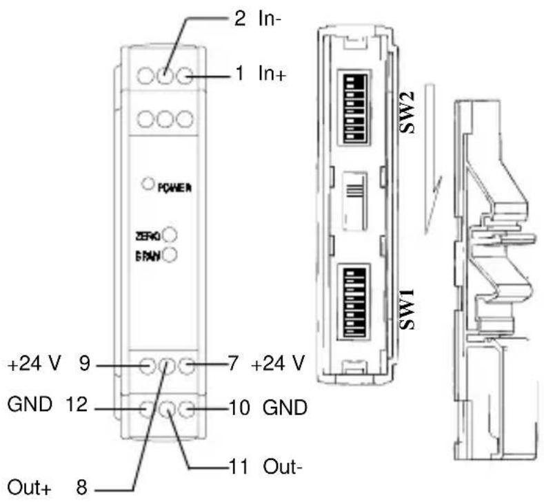
Figure 1: Terminal Wiring Diagram
Table 1: Input range setting(SW2)
| Input Range(SW2) | |||||||||
| Bipolar | Unipolar | 1 | 2 | 3 | 4 | 5 | 6 | 7 | 8 |
| ±10mV | 0~10mV | ■ | |||||||
| ±50mV | 0~50 | mV | ■ | ||||||
| ±100mV | 0~100 | mV | ■ | ||||||
| ±0.5V | 0~0.5 | V | ■ | ||||||
| ±1V | 0~1 | V | ■ | ||||||
| ± 5 | V ( * ) | 0 | ~ | 5 | |||||
| ±10V | 0~10 | V | |||||||
| ±20mV | 0~20mA | ■ | |||||||
■:ON
*:Factory default setting
v (
Table 2: Output range setting (SW1)
| Output Range(SW1) | ||||||||||
| Output Range | Input Range | 1 | 2 | 3 | 4 | 5 | 6 | 7 | 8 | |
| ±5V(*) | ±10mV, ±50mV, ±100mV, ±0.5V, ±1V, ±5V,±20mA | ■ | ■ | ■ | ||||||
| 0~10mV, 0~50mV, 0~100mV, 0~0.5V, 0~1V, 0~5V, 0~20mA | ■ | ■ | ■ | ■ | ||||||
| 0~20mA | ±10mV, ±50mV, ±100mV, ±0.5V, ±1V, ±5V,±20mA | ■ | ■ | ■ | ||||||
| 0~10mV, 0~50mV, 0~100mV, 0~0.5V, 0~1V, 0~5V, 0~20mA | ■ | ■ | ||||||||
| 0~10V | ■ | ■ | ■ | |||||||
| ±10V | ±10mV, ±50mV, ±100mV, ±0.5V, ±1V, ±5V,±20mA | ■ | ■ | |||||||
| ±10V | ■ | ■ | ■ | |||||||
| 0~10 V | ±10mV, ±50mV, ±100mV, ±0.5V, ±1V, ±5V,±20mA | ■ | ■ | ■ | ||||||
| 0~10mV, 0~50mV, 0~100mV, 0~0.5V, 0~1V, 0~5V, 0~20mA | ■ | ■ | ||||||||
| 0~10V | ■ | ■ | ■ | |||||||
■: ON
* Factory default setting
Calibration for input/output
- Disconnect power and set the input range (SW2) and output range (SW1) to the desired setting, then apply the power.
**Define the following variables for calibration use.
--Low_cali_input = Min_input + Full Scalar Input * 0.05;
--High_cali_input = Max_input - Full Scalar Input * 0.05;
--Low_cali_output = Min_output + Full Scalar Output * 0.05;
--High_cali_output = Max_output - Full Scalar Output * 0.05;
- Input the Low_cali_input signal; read the Low_real_output signal;
3.Input the High_cali_input signal;read the High_real_output signal; - Adjust variable resistor of SPAN and repeat step 2 & 3 to meet the following condition
(High_cali_output - Low_cali_output) = (Low_real_output - High_real_output)----eq1
- Adjust variable resistor of ZERO and repeat step 2 & 3 to meet the following condition
Low_real_output = Low_cali_output----eq2
High_real_output = High_cali_output----eq3
- If eq2, eq3 fail to meet your requirement, repeat steps 4,5 until success in step 5
flowchart
graph LR
    A["mV/mA"] --> B["250 Ω"]
    B --> C["Instrumentation Amplifier"]
    C --> D["PGA"]
    D --> E["Isolation"]
    E --> F["Active LPF"]
    F --> G["Low Pass Filter"]
    G --> H["Voltage Output"]
    G --> I["Current Output"]
    J["Gain select switch"] --> D
    K["+15 V"] --> L["Filter"]
    L --> M["Power Converter"]
    M --> N["+24 V_DC"]
    O["+15 V"] --> P["Filter"]
    P --> Q["Power Input"]
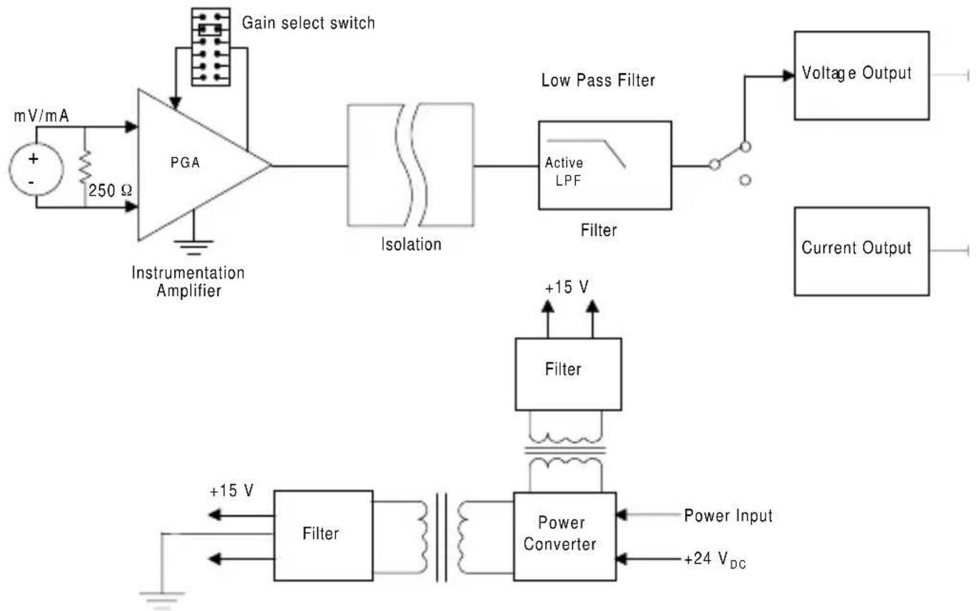
Figure 2: Block Diagram
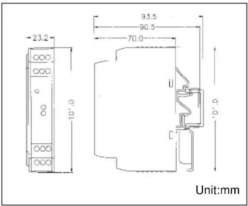
Dimensions

Brand : Advantech
Model : ADAM-3014
Category : Uncategorized