Aura Smart LTM-A401S-WUS - Thermostat Levoit - Free user manual and instructions
Find the device manual for free Aura Smart LTM-A401S-WUS Levoit in PDF.

| Product Type | Smart Thermostat |
| Brand | Levoit |
| Model | Aura Smart LTM-A401S-WUS |
| Dimensions | 4.68 x 3.49 x 0.98 inches (11.88 x 8.86 x 2.50 cm) |
| Weight | 0.37 lb (0.17 kg) |
| Power Supply | AC 24V, 60Hz |
| Rated Power | 3W |
| Connectivity | 2.4GHz Wi-Fi (802.11 b/g/n), Zigbee 3.0 |
| Temperature Setting Range | 32°F – 99°F (0°C – 37°C) |
| Temperature Display Range | 32°F – 104°F (0°C – 40°C) |
| Temperature Increments | 1°F (0.5°C) |
| Humidity Display Range | 0 – 99% RH |
| Humidity Increments | 1% |
| Operating Conditions | 32°F – 122°F (0°C – 50°C), 5–95% RH non-condensing |
| Storage Conditions | -4°F – 140°F (-20°C – 60°C), 5–95% RH non-condensing |
| System Compatibility | 2H/2C Conventional, 4H/2C Heat Pump, Dual Fuel, separate Rc/Rh |
| Main Functions | HVAC modes (Heat, Cool, Auto, Smart, Aux, Off), Fan modes (On, Auto, Circulate), Schedule, Vacation, My Routines, Weather, Sensors, Usage, Smart Scenes, Remote control via VeSync app |
| Wi-Fi Requirements | 2.4GHz secure network |
| App | VeSync (free) |
| Voice Assistant | Amazon Alexa, Google Assistant (via VeSync) |
| Safety Certifications | FCC Part 15 Class B |
| Included Accessories | Backplate, Power Extender Kit, Screws (4), Wall Anchors (4), Wire Tag Set, User Manual |
| Cleaning | Wipe with a soft, dry cloth. Do not use water or cleaning agents. |
Frequently Asked Questions - Aura Smart LTM-A401S-WUS Levoit
User questions about Aura Smart LTM-A401S-WUS Levoit
0 question about this device. Answer the ones you know or ask your own.
Ask a new question about this device
Download the instructions for your Thermostat in PDF format for free! Find your manual Aura Smart LTM-A401S-WUS - Levoit and take your electronic device back in hand. On this page are published all the documents necessary for the use of your device. Aura Smart LTM-A401S-WUS by Levoit.
USER MANUAL Aura Smart LTM-A401S-WUS Levoit
Questions or Concerns?
Please contact us Mon–Fri, 9:00 am–5:00 pm PST/PDT at support@levoit.com or at (888) 726-8520.
Table of Contents
Package Contents 2
Specifications 3
Safety Information 6
Installation Guide 8
Removing Your Old Thermostat 9
Installing Thermostat with a C Wire 15
Installing Thermostat without a C Wire 22
Wiring Diagrams 36
Getting Started 41
Basic Functions 43
VeSync App Setup 59
VeSync App Functions 60
Troubleshooting 61
Warranty Information 68
Customer Support 73
Package Contents
1 x Aura Smart Thermostat
1 x Backplate
1 x Power Extender Kit
4 x Screw
4 x Wall Anchor
1 x User Manual
1 x Wire Tag Set
Specifications
| Power Supply AC 24V, 60Hz | |
| Rated Power 3W | |
| Dimensions 4.68 x 3.49 x 0.98 | n / 11.88 x8.86 x 2.50 cm |
| Weight 0.37 lb / 0.17 kg | |
| Connectivity 2.4GHz Wi-Fi (802.11 b/g/n),Zigbee 3.0 (for room sensors) | |
| Temperature Range Setting Range: 32°–99°F /0°–37°CDisplay Range: 32°–104°F /0°–40°CNote:The thermostat settings are limited to 99°F. However,the thermostat can read up to 104°F. | |
| Temperature Increments 1°F / 0.5°C | |
| Relative Humidity (RH) Display Range | 0–99% |
| Relative Humidity (RH) Increments | 1% |
| Operating Conditions Temperature: 32°–122°F / 0°–50°C Relative Humidity: 5–95% (non-condensing) | |
| Storage Conditions Temperature: -4°–140°F / -20°–60°C Relative Humidity: 5–95% (non-condensing) | |
SPECIFICATIONS (CONT.)
Compatibility
• 2H/2C Conventional Systems
• 4H/2C Heat Pump Systems or Dual Fuel Systems
• Systems with Rc and Rh Terminals (for separate heating and cooling power supplies)
Note: To access additional smart functions, download the free VeSync app (see page 59).
READ AND SAVE THESE INSTRUCTIONS SAFETY INFORMATION
Please read and follow all instructions and safety guidelines in this manual.
Installation
- Before installing and wiring, TURN OFF your HVAC system by turning off the appropriate switch or locking the appropriate circuit breaker in the OFF position.
- Only install the thermostat if you are comfortable with electrical work. If not, contact a qualified electrician. Improper installation will increase risk of fire, electric shock, and other injuries.
• The thermostat must be installed and used in accordance with the National Electric Code (NEC) or your local electrical code. - Do not install the thermostat with wet hands.
Note: Levoit cannot guarantee the quality of installation, and cannot cover associated costs.
General Safety
• Only install and use the thermostat indoors, in a dry location, and avoiding extreme heat and freezing temperatures
- Do not modify the thermostat hardware or software.
• Not for commercial use. Household use only.
Function Diagram
A. Smart Thermostat
B. Backplate
C. Power Extender Kit (PEK)
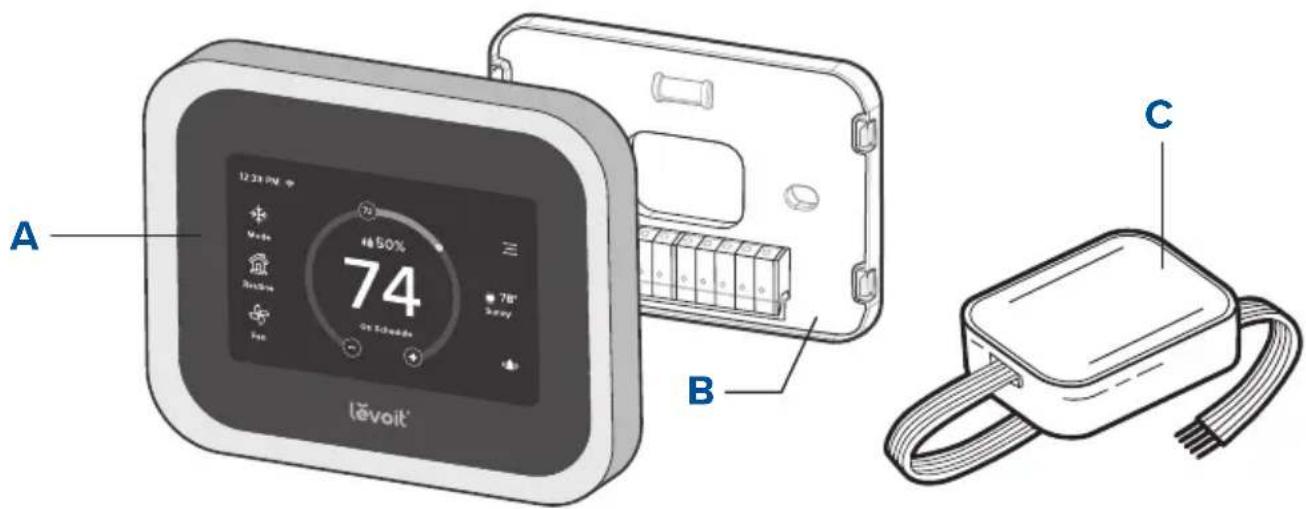
text_image
A Level 10 72 50% 74 86 78" Sunny B CINSTALLATION GUIDE
What You'll Need
- Electric drill
• 3/16-inch drill bit - Small flat head screwdriver
• Philips head screwdriver
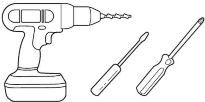
natural_image
Line drawing of a drill press and two screwdrivers (no text or symbols)Removing Your Old Thermostat
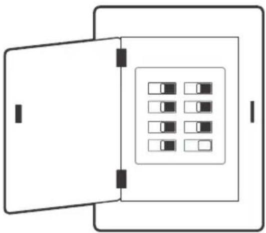
1. Turn off your HVAC system
WARNING: For your safety, you must turn off your HVAC system before removing your old thermostat.
Every HVAC system is different, but usually you turn off a master switch or switch the system off in your home's breaker box. [Figure 1.1]
Note: The master switch or breaker box is often found in your basement, attic, garage, or utility closet.
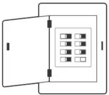
natural_image
Simple line drawing of a door opening and containing a grid of small squares inside a rectangular frame (no text or symbols)Breaker Box
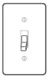
natural_image
Simple line drawing of a light switch or lever (no text or symbols)Switch
TURN OFF
Figure 1.1
Confirm that the HVAC system is turned off by adjusting the temperature on the thermostat, waiting a few minutes, and making sure that the HVAC does not turn on.
REMOVING YOUR OLD THERMOSTAT (CONT.)
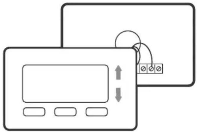
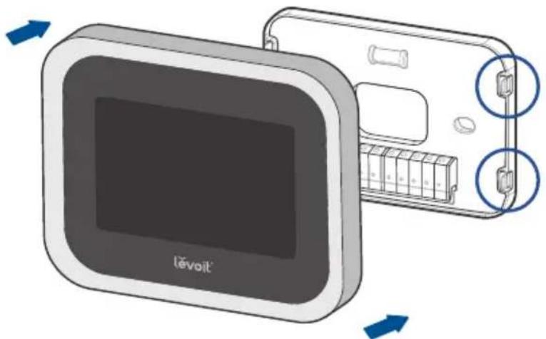
2. Remove your old thermostat
Remove your old thermostat from the wall. Every thermostat is different, but usually you will need to push a tab on the edge of the thermostat and separate the thermostat from the backplate. [Figure 1.2]
Note: Only remove the old thermostat. Do not remove the backplate from the wall yet.
natural_image
Diagram showing two overlapping electronic devices with control buttons and a display screen, no text or symbols present.Figure 1.2
REMOVING YOUR OLD THERMOSTAT (CONT.)
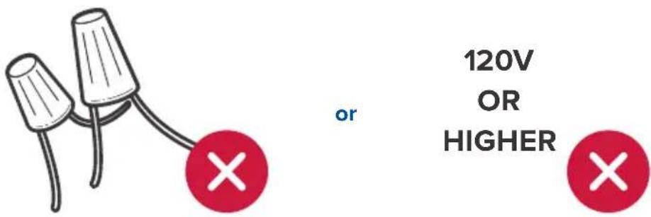
3. Check for compatibility
Inspect the wires leading into the backplate.
If you find thick wires with wire nuts, or if the voltage of your HVAC system is 120V or higher, then your system is not compatible with this smart thermostat. [Figure 1.3]
Contact Customer Support (see page 73).
text_image
120V OR HIGHERFigure 1.3
REMOVING YOUR OLD THERMOSTAT (CONT.)
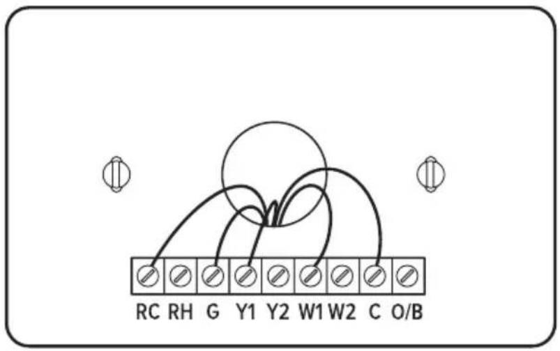
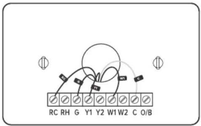
4. Take a photo
Before removing wires, take a picture of how the wires connect to the terminal of your old thermostat. [Figure 1.4] You may need to reference this photo later.
text_image
RC RH G Y1 Y2 W1 W2 C O/BFigure 1.4
REMOVING YOUR OLD THERMOSTAT (CONT.)
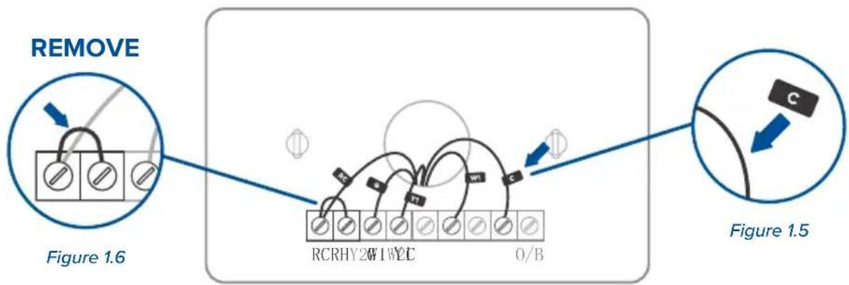
- Find the Thermostat Labels in the included wire tag set. Label the wires according to the corresponding terminals.
[Figure 1.5]
If there are any jumper wires (wires connecting different terminals together), do not label these wires. [Figure 1.6] Remove them and store them with your old thermostat.
The terminals on your old thermostat may already have 2 different sets of labeling—one set for a conventional HVAC system and one set for a heat pump system. If your system has a heat pump, make sure to follow the heat pump labeling.
Note: If you are unsure whether your system has a heat pump, we recommend that you research your HVAC system online or contact Customer Support (see page 73).
flowchart
graph TD
    A["REMOVE"] --> B["Figure 1.6"]
    B --> C["RCRHY2W1W2C"]
    C --> D["O/B"]
    D --> E["Figure 1.5"]
    E --> F["C"]
REMOVING YOUR OLD THERMOSTAT (CONT.)
- Carefully disconnect the wires. Each thermostat is different, but usually you use a Philips head screwdriver to loosen a screw or press a release button to remove the wire.
Important:
- Check if you have a C wire connected to your old thermostat. The C wire is used to provide power to the thermostat. [Figure 1.7]
• If you have a C wire, go to Installing Thermostat with a C Wire (page 15).
• If you do not have a C wire, go to Installing Thermostat without a C Wire (page 22).
text_image
RC RH G Y1 Y2 W1 W2 C O/BFigure 1.7
Installing Thermostat with a C Wire:
Note: If your system has a C wire, you do not need to install the power extender kit (PEK). The thermostat will use the C wire for power.
1. Remove the old backplate
Unscrew the old backplate from the wall. [Figure 2.1] Hold the wires and carefully pull the backplate from the wall, making sure the wires do not fall into the wall.
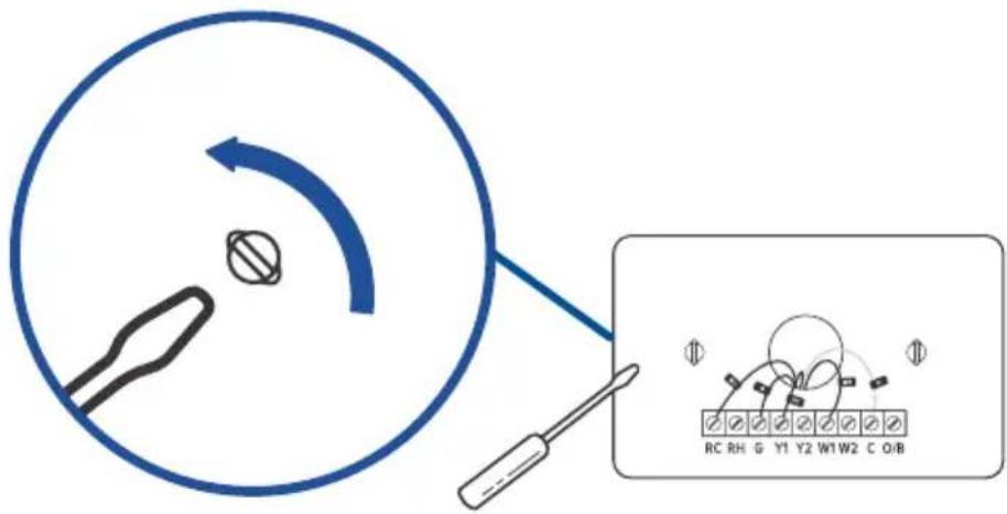
text_image
Diagram illustrating a tool interacting with a circular component, alongside a schematic diagram showing labeled components and directional arrows.Figure 2.1
INSTALLING THERMOSTAT WITH A C WIRE (CONT.)
2. Attach the new backplate
Insert the wires through the hole in the new backplate. Use an electric drill to attach the backplate to the wall with the provided wall anchors and screws. [Figure 2.2]
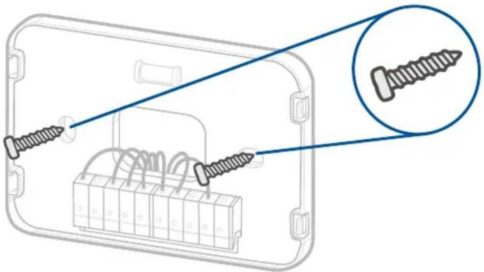
natural_image
Diagram of screw installation into a device housing, showing two screws inserted and one with a magnified inset (no text or symbols)Figure 2.2
INSTALLING THERMOSTAT WITH A C WIRE (CONT.)
3. Connect the wires
Connect the wires to the corresponding terminals on the backplate (see Wiring Diagrams, page 36). [Figure 2.3] When you are finished, take a picture.
You may need to refer to the connections in this photo while setting up the thermostat.
text_image
Re Rh Cx G W1 #2 Y1 Y2 O/B PEK O C G WT Y1 O/B Y1 Y2 O/B PEFigure 2.3
INSTALLING THERMOSTAT WITH A C WIRE (CONT.)
About R Wires:
- If you have more than one R wire (R wires include R, Rc, and Rh):
- Connect the R or Rc wire to the Rc terminal, and connect the Rh wire to the Rh terminal.
- If you only have one R wire (R wires include R, Rc, and Rh):
- Connect the R wire—R, Rc, or Rh—to the Rc terminal.
INSTALLING THERMOSTAT WITH A C WIRE (CONT.)
4. Adjust the jumper (DIP switch)
Turn the thermostat over. Adjust the jumper switch as follows [Figure 2.4]:
- If you have connected wires to both the Rc and Rh terminals on the backplate, then adjust the jumper switch to OFF.
- If not, then adjust the jumper switch to ON.
Back of Thermostat
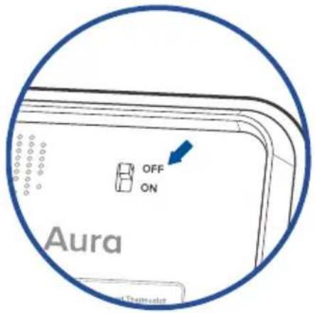
text_image
OFF ON Aura 4 ThematolFigure 2.4
INSTALLING THERMOSTAT WITH A C WIRE (CONT.)
5. Place the thermostat
Make sure all wiring is pushed inside the wall. Carefully press the thermostat into the backplate until it clicks securely into place. [Figure 2.5]
Note: Cover any gaps in the wall around the thermostat. Airflow from holes may affect temperature readings.
natural_image
Illustration of a device with a screen and battery, showing internal components and directional arrows (no text or symbols)Figure 2.5
INSTALLING THERMOSTAT WITH A C WIRE (CONT.)
6. Turn on your HVAC system
Turn your HVAC system back on. [Figure 2.6] If installation was successful, the thermostat display screen will turn on. You are now ready to set up your thermostat (see Getting Started, page 41).
Note: If the thermostat display does not turn on, please see Troubleshooting, page 61.
natural_image
Diagram of a device with an open panel and a grid of small rectangular blocks inside, no text or symbols present.Breaker Box

natural_image
Simple line drawing of a rectangular object with two circular symbols at the top (no text or labels)Switch
TURN ON
Figure 2.6
Installing Thermostat without a C Wire
If your system does not have a C wire, you must install the power extender kit (PEK). The PEK connects to your thermostat wires to create a circuit that provides power to your thermostat.
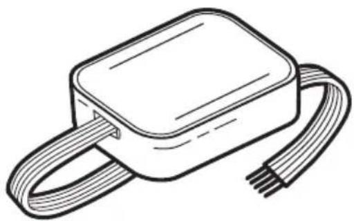
Power Extender Kit (PEK)
The PEK has 4 terminals on one side and 5 terminals on the other side.
- The side with 4 terminals is not pre-wired. Connect the thermostat wires to the terminals.
- The side with 5 terminals is pre-wired to connect to your HVAC control board.
natural_image
Line drawing of a rectangular electronic device with coiled wires (no text or symbols)INSTALLING THERMOSTAT WITHOUT A C WIRE (CONT.)
Compatibility
The power extender kit (PEK) requires that your HVAC system has one of the following sets of wires:
4 Wires: W/W1, Y/Y1, G, and R (including Rc or Rh)
or
3 Wires: Y/Y1, G, and R (including Rc or Rh)
If your HVAC does not have these wires, your system may not be compatible with the PEK.
INSTALLING THERMOSTAT WITHOUT A C WIRE (CONT.)
1. Identify the thermostat terminals on your HVAC
Find the control board of your HVAC system (typically, there is a cover you can pull off to reveal the control board). [Figure 3.1]
Take a picture of the wires connected to the terminals that control your thermostat. You may need to reference this photo later.
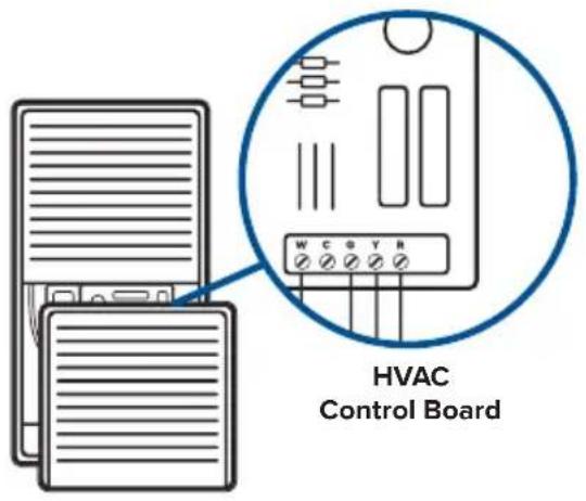
text_image
HVAC Control BoardFigure 3.1
INSTALLING THERMOSTAT WITHOUT A C WIRE (CONT.)
2. Label the thermostat wires
Find the PEK Labels in the included wire tag set. Use these to label the wires on the HVAC's control board according to the corresponding terminals. [Figure 3.2]
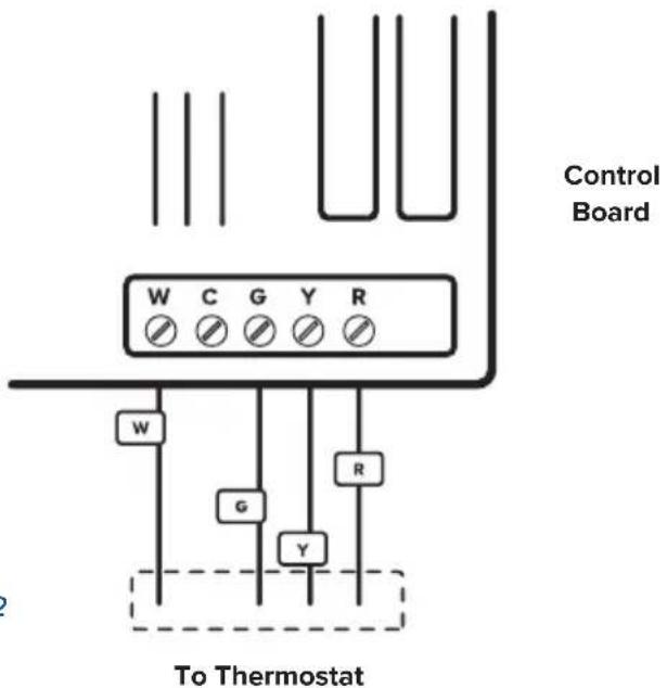
text_image
Control Board W C G Y R W G Y R To ThermostatFigure 3.2
INSTALLING THERMOSTAT WITHOUT A C WIRE (CONT.)
3. Disconnect the thermostat wires
If you're using 4 wires, carefully disconnect the W/W1, G, Y/Y1, and R wires from the control board terminals. [Figure 3.3]
Note: If you're only using 3 wires, you will only need to disconnect the G, Y/Y1, and R wires.
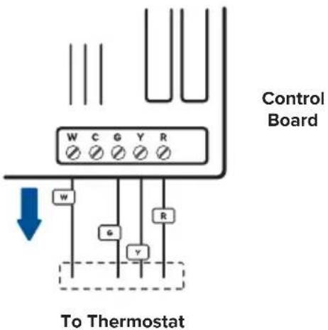
text_image
Control Board W C G Y R w G Y R To ThermostatFigure 3.3
INSTALLING THERMOSTAT WITHOUT A C WIRE (CONT.)
4. Connect the thermostat wires to the PEK
Connect the thermostat wires from the control board to the corresponding terminals on the PEK. [Figure 3.4]
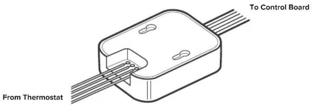
text_image
To Control Board From ThermostatFigure 3.4
INSTALLING THERMOSTAT WITHOUT A C WIRE (CONT.)
5. Connect the PEK wires to the control board
Connect the wires on the pre-wired side of the PEK (W, C, G, Y, and R wires) to the corresponding 5 terminals on the control board. [Figure 3.5]
Take a picture of the wires connected to the PEK and the terminals on the control board.
You may need to reference this photo later.
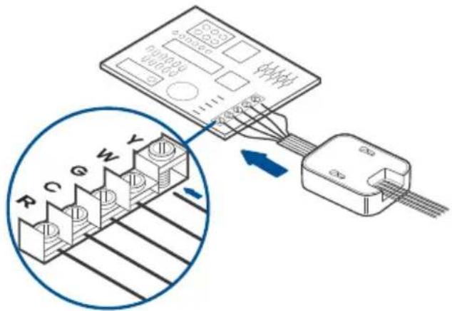
text_image
Diagram showing connection between a device with labeled pins (R, C, G, W, Y) and an attached cable, with a magnified inset highlighting internal structure.Figure 3.5
INSTALLING THERMOSTAT WITHOUT A C WIRE (CONT.)
6. Position the PEK
The PEK should be securely placed between the thermostat wiring and the control board. [Figure 3.6] Replace the cover on your HVAC system, then return to your thermostat.
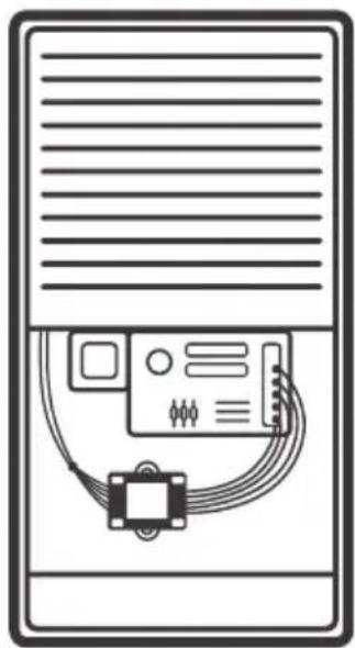
natural_image
Illustration of a server rack with an electronic device connected to a cable and a small sensor (no text or symbols)Figure 3.6
INSTALLING THERMOSTAT WITHOUT A C WIRE (CONT.)
7. Remove the old backplate
Unscrew the old backplate from the wall. [Figure 3.7] Hold the wires and carefully pull the backplate from the wall, making sure the wires do not fall into the wall.
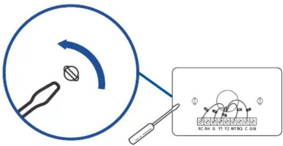
text_image
Diagram showing a tool interacting with a circular component and a schematic diagram of a device with labeled pins (RC, RH, G, Y1, Y2, W1, W2, C, O/B).Figure 3.7
INSTALLING THERMOSTAT WITHOUT A C WIRE (CONT.)
8. Attach the new backplate
Insert the wires through the hole in the new backplate. Use an electric drill to attach the backplate to the wall with the provided wall anchors and screws. [Figure 3.8]
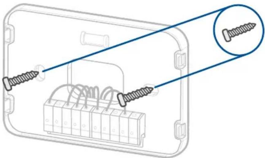
natural_image
Diagram of screw installation inside an electronic device, showing two screws inserted into a housing with coiled wires (no text or labels)Figure 3.8
INSTALLING THERMOSTAT WITHOUT A C WIRE (CONT.)
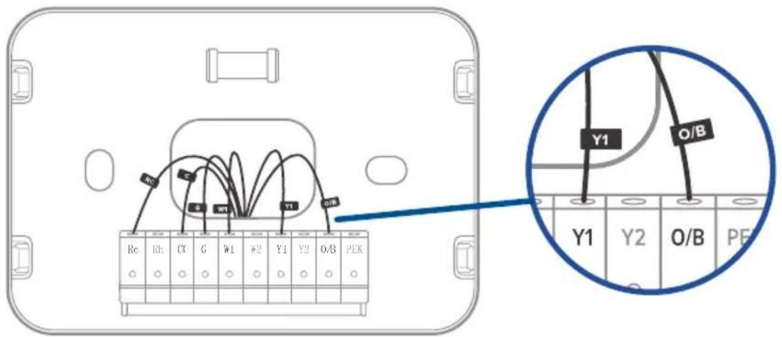
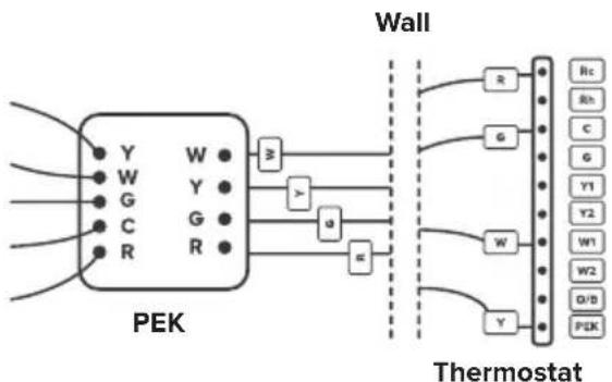
9. Connect the wires
First, connect the following 3 wires:
- R wire (R wires include R, Rc, and Rh) to the Rc terminal
• G wire to the C terminal
• Y/Y1 wire to the PEK terminal
Then, connect the remaining wires to the corresponding terminals on the backplate (see Wiring Diagrams, page 36).
[Figure 3.9] When you are finished, take a picture. You may need to refer to the connections in this photo while setting up the thermostat.
flowchart
graph TD
    subgraph "PEK"
        Y1["Y"] --> W1["W"]
        W1 --> Y2["Y"]
        Y2 --> G1["G"]
        G1 --> C1["C"]
        C1 --> R1["R"]
        Y3["W"] --> W2["W"]
        W2 --> Y4["Y"]
    end
    subgraph "Wall"
        R1["R"] --> Thermostat["Thermostat"]
        G1["G"] --> Thermostat
        Y1["Y1"] --> Thermostat
        Y2["Y2"] --> Thermostat
        W1["W"] --> Thermostat
        W2["W2"] --> Thermostat
        D/B["D/B"] --> Thermostat
        Y4["Y"] --> Thermostat
    end
    style "PEK" fill:#f9f,stroke:#333
    style "Wall" fill:#ccf,stroke:#333
Figure 3.9
INSTALLING THERMOSTAT WITHOUT A C WIRE (CONT.)
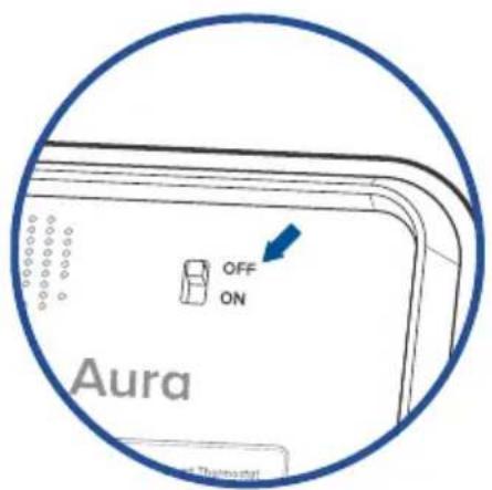
10. Adjust the jumper (DIP switch)
Turn the thermostat over. Adjust the jumper switch as follows [Figure 3.10]:
- If you have connected wires to both the Rc and Rh terminals on the backplate, then adjust the jumper switch to OFF.
- If not, then adjust the jumper switch to ON.
Back of Thermostat
text_image
OFF ON Aura ThermostatFigure 3.10
INSTALLING THERMOSTAT WITHOUT A C WIRE (CONT.)
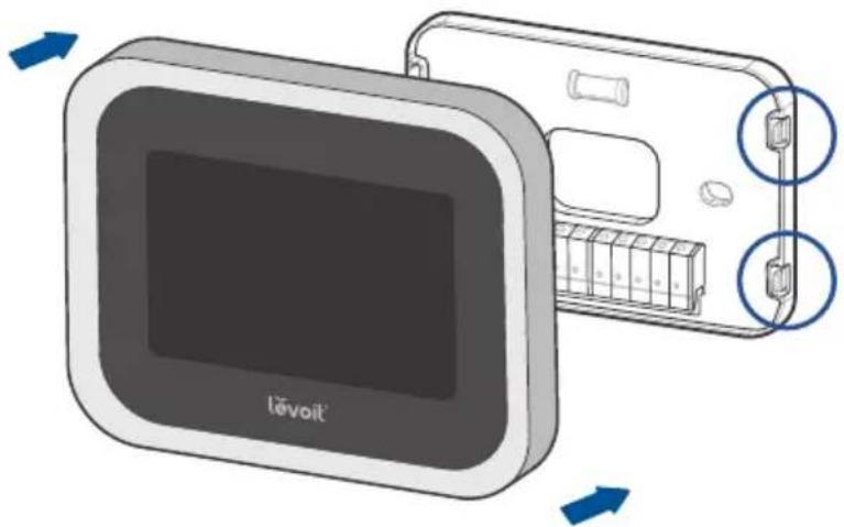
11. Place the thermostat
Make sure all wiring is pushed inside the wall. Carefully press the thermostat into the backplate until it clicks securely into place. [Figure 3.11]
Note: Cover any gaps in the wall around the thermostat.
Airflow from holes may affect temperature readings.
natural_image
Illustration of a device with a screen and battery, showing internal components and directional arrows (no text or symbols)Figure 3.11
INSTALLING THERMOSTAT WITHOUT A C WIRE (CONT.)
12. Turn on your HVAC system
Turn your HVAC system back on. [Figure 3.12] If installation was successful, the thermostat display screen will turn on. You are now ready to set up your thermostat (see Getting Started, page 41).
Note: If the thermostat display does not turn on, please see Troubleshooting, page 61.

natural_image
Diagram of a device with an open lid and internal grid pattern (no text or symbols)Breaker Box
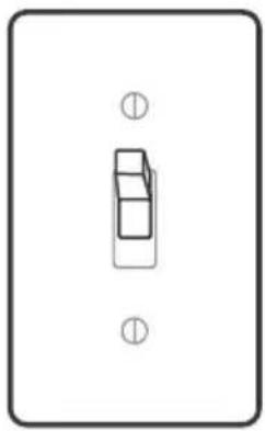
natural_image
Simple line drawing of a rectangular object with two circular symbols at the top (no text or labels)Switch
TURN ON
Figure 3.12
Wiring Diagrams
The following are wiring diagrams for common HVAC systems. You may be able to use these for reference when installing your thermostat.
Conventional Heating/Cooling System - C Wire
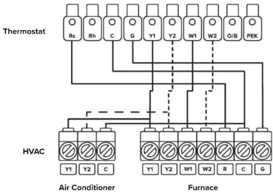
flowchart
graph TD
    A["Thermostat"] --> B["Rc"]
    A --> C["Rh"]
    A --> D["C"]
    A --> E["G"]
    A --> F["Y1"]
    A --> G["Y2"]
    A --> H["W1"]
    A --> I["W2"]
    A --> J["O/B"]
    A --> K["PEK"]
    L["HVAC"] --> M["Y1"]
    L --> N["Y2"]
    L --> O["C"]
    P["Air Conditioner"] --> Q["∅"]
    P --> R["∅"]
    S["Furnace"] --> T["∅"]
    S --> U["∅"]
    S --> V["∅"]
    S --> W["∅"]
    S --> X["∅"]
    S --> Y["∅"]
    S --> Z["∅"]
    S --> AA["∅"]
For 2-Stage Heating/Cooling Systems (If Applicable)
WIRING DIAGRAMS (CONT.)
Conventional Heating/Cooling System - No C Wire (Used with PEK)
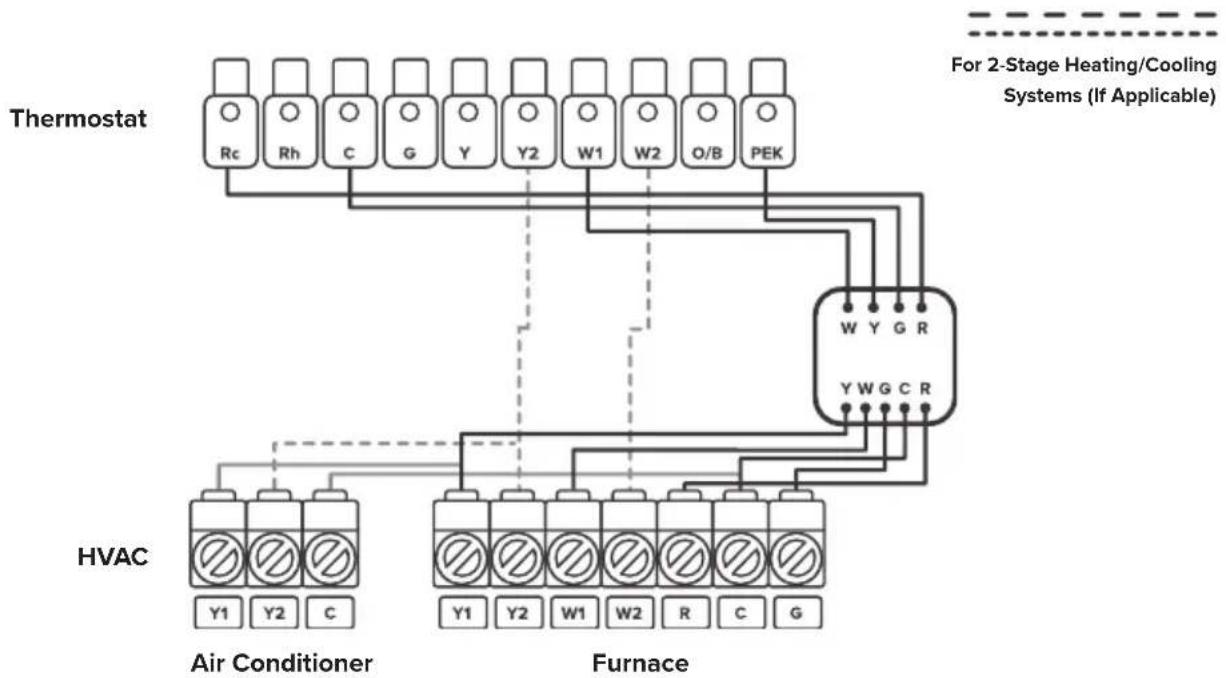
flowchart
graph TD
    A["Thermostat"] --> B["Rc"]
    A --> C["Rh"]
    A --> D["C"]
    A --> E["G"]
    A --> F["Y"]
    A --> G["Y2"]
    A --> H["W1"]
    A --> I["W2"]
    A --> J["O/B"]
    A --> K["PEK"]
    L["HVAC"] --> M["Y1"]
    L --> N["Y2"]
    L --> O["C"]
    P["Air Conditioner"] --> Q["Y1"]
    P --> R["Y2"]
    P --> S["W1"]
    P --> T["W2"]
    P --> U["R"]
    P --> V["C"]
    P --> W["G"]
    X["Furnace"] --> Y["Y1"]
    X --> Z["Y2"]
    X --> AA["W1"]
    X --> AB["W2"]
    X --> AC["R"]
    X --> AD["C"]
    X --> AE["G"]
    AF["For 2-Stage Heating/Cooling Systems (If Applicable)"] --> AG["W Y G R"]
    AF --> AH["Y W G C R"]
WIRING DIAGRAMS (CONT.)
Heat Pump (Air or Geothermal) with Auxiliary Heat - C Wire
Thermostat
HVAC
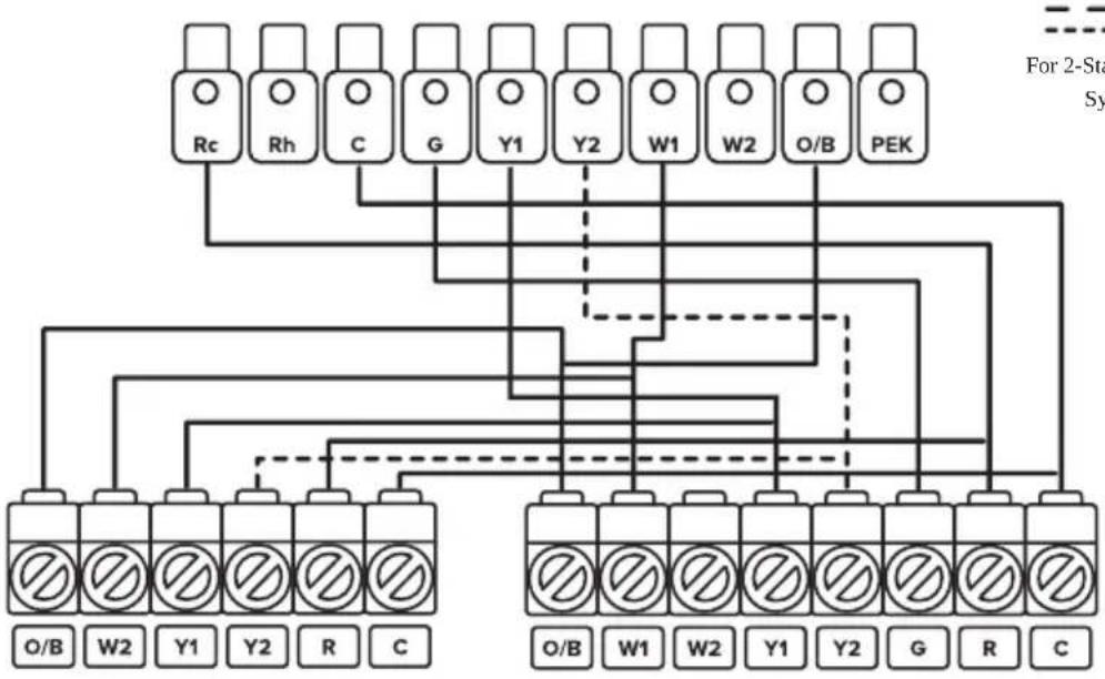
flowchart
graph TD
    A["Rc"] --> B["For 2-Stage System"]
    C["Rh"] --> B
    D["C"] --> B
    E["G"] --> B
    F["Y1"] --> B
    G["Y2"] --> B
    H["W1"] --> B
    I["W2"] --> B
    J["O/B"] --> K["PEK"]
    L["O/B"] --> M["Terminal Block"]
    N["W2"] --> M
    O["Y1"] --> M
    P["Y2"] --> M
    Q["R"] --> M
    R["C"] --> M
Heat Pump Air Handler
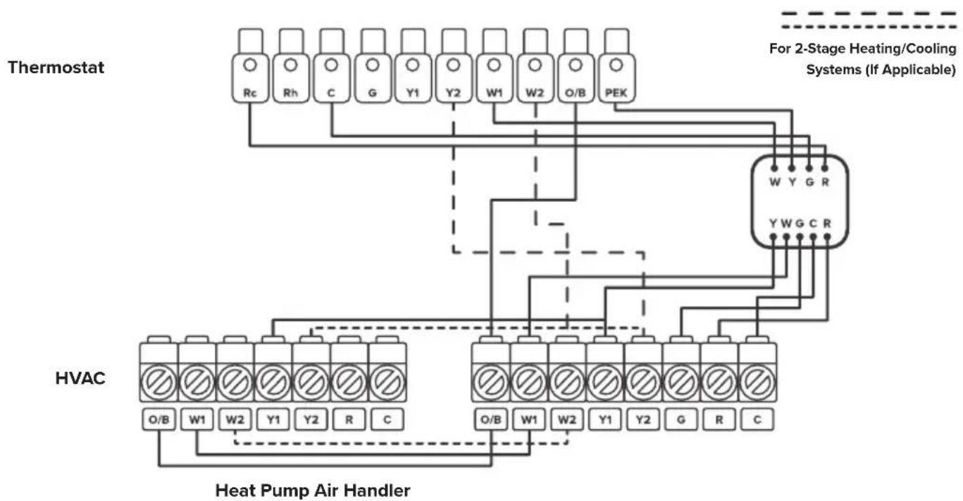
WIRING DIAGRAMS (CONT.)
Heat Pump (Air or Geothermal) with Auxiliary Heat – No C Wire (Used with PEK)
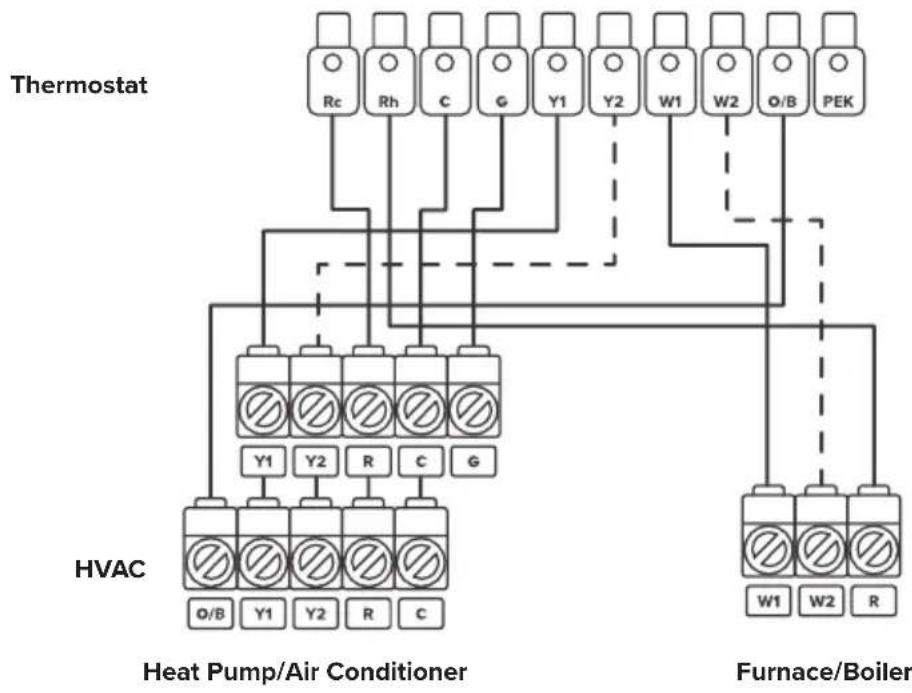
Heat Pump (Air or Geothermal) with Auxiliary Heat, Two Transformer System – C Wire
flowchart
graph TD
    A["Thermostat"] --> B["Re"]
    A --> C["Rh"]
    A --> D["C"]
    A --> E["G"]
    A --> F["Y1"]
    A --> G["Y2"]
    A --> H["W1"]
    A --> I["W2"]
    A --> J["O/B"]
    A --> K["PEK"]
    L["HVAC"] --> M["Y1"]
    L --> N["Y2"]
    L --> O["R"]
    L --> P["C"]
    L --> Q["G"]
    R["Heat Pump/Air Conditioner"] --> S["O/B"]
    R --> T["Y1"]
    R --> U["Y2"]
    R --> V["R"]
    R --> W["C"]
    X["Furnace/Boiler"] --> Y["W1"]
    X --> Z["W2"]
    X --> AA["R"]
For 2-Stage Heating/Cooling Systems (If Applicable)
Getting Started
Setup Wizard & Configuration
Note: The smart thermostat is continually being improved and may change over time. If there are any differences, follow the on-screen instructions.
- When the thermostat first powers on, the welcome screen will appear. Begin the setup wizard.
-
Refer to the photo of the backplate terminals to find which terminals have wires connected to them, then select these terminals on the screen.
-
The thermostat will automatically determine what type of HVAC system you have.
- If there is a wire connected to the O/B terminal, that means that you have a heat pump system, and a prompt will appear on-screen. Select how your O/B reversing valve is engaged.
Note: Usually, the O/B engages when on cool.
- Select the type of fuel system your furnace uses. This will affect how the fan works during heating.
GETTING STARTED (CONT.)
-
Select your desired Eco Level.
-
A higher Comfort level focuses on precise temperature control, but uses more energy.
• A higher Eco level focuses on energy efficiency, but will not control temperature as precisely. -
If you are unsure what to select, choose "Balance." This is a balance of Comfort and Eco.
-
Select whether you would like to connect the thermostat to the VeSync app (see VeSync App Setup, page 59). If you don't want to connect to VeSync right now, you can do it later.
Note: Download the free VeSync app to control your smart thermostat remotely and use more functions and features (see VeSync App Functions, page 60).
- Set your time zone and current time.
Note: This will set automatically if you are connected to the VeSync app.
- The setup wizard is complete. To start your thermostat, select an HVAC mode (see HVAC Modes, on page 45).
Basic Functions
Note: The smart thermostat is continually being improved and may change over time. If there are any differences, follow the on-screen instructions.
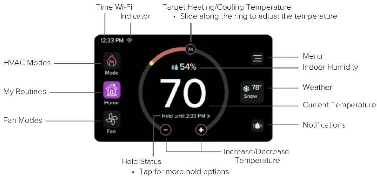
Home Screen
text_image
Time Wi-Fi Indicator Target Heating/Cooling Temperature • Slide along the ring to adjust the temperature 12:33 PM 74 54% 70 HVAC Modes Mode My Routines Home Fan Modes - Hold until 2:33 PM > Menu Indoor Humidity Weather Current Temperature Notifications Hold Status • Tap for more hold options Increase/Decrease TemperatureBASIC FUNCTIONS (CONT.)
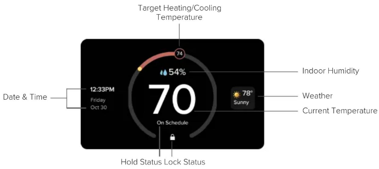
Standby Screen
The Standby Screen will display after a period of no activity. You can customize the standby screen timeout in the Settings, page 56).
text_image
Target Heating/Cooling Temperature 74 54% 12:33PM Friday Oct 30 70 On Schedule Date & Time Indoor Humidity Weather 78° Sunny Current Temperature Hold Status Lock StatusBASIC FUNCTIONS (CONT.)
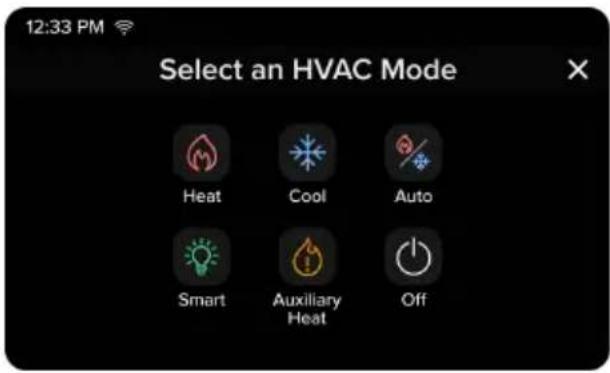
HVAC Modes
text_image
12:33 PM Select an HVAC Mode Heat Cool Auto Smart Auxiliary Heat OffNote: HVAC modes can be used manually or with your scheduled routines (see My Routines, page 51). A manual setting will override your schedule.
Heat: Heating only
Cool: Cooling only
Auto: The thermostat will automatically adjust heating/cooling to reach a target temperature range.
Smart: The thermostat will automatically adjust heating/cooling to reach a set target temperature.
Auxiliary Heat: Use Auxiliary Heat to warm up the room faster if the heat pump is not sufficient.
Note: Only available with heat pump systems where a W wire is connected.
Off: Turns off heating and cooling.
Note: You can still use the fan while the HVAC is off.
BASIC FUNCTIONS (CONT.)
Fan Modes
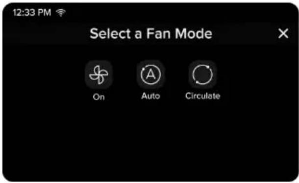
text_image
12:33 PM Select a Fan Mode On Auto CirculateOn: The fan runs continuously.
Auto: The fan automatically turns on when the HVAC is cooling or heating.
Note: Auto fan mode turns off if the HVAC is not cooling or heating.
Circulate: The fan turns on for 20 minutes (default) every hour to circulate air. You can adjust the amount of time the fan is on in Settings, page 56.
BASIC FUNCTIONS (CONT.)
Weather
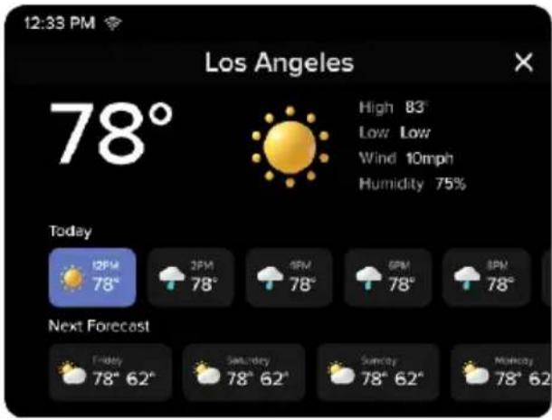
text_image
12:33 PM Los Angeles 78° High 83° Low Low Wind 10mph Humidity 75% Today 12PM 78° 2PM 78° 4PM 78° 6PM 78° 8PM 78° Next Forecast Friday 78° 62° Saturday 78° 62° Sunday 78° 62° Monday 78° 62°Use the Weather screen to view the latest weather information, including high and low temperatures, humidity, and the upcoming forecast.
Note: Only available if your thermostat is connected to the VeSync app, your home location is set, and your region is the United States.
BASIC FUNCTIONS (CONT.)
Menu
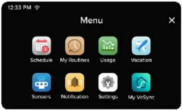
text_image
12:33 PM Menu Schedule My Routines Usage Vacation Sensors Notification Settings My VeSyncPress the Menu icon to access additional functions and settings.
BASIC FUNCTIONS (CONT.)
Schedule
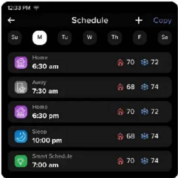
text_image
12:33 PM Schedule Su M Tu W Th F Sa Home 6:30 am 70 72 Away 7:30 am 68 74 Home 6:30 pm 70 72 Sleep 10:00 pm 68 74 Smart Schedule 7:00 am 70 74Use the Schedule screen to automatically run routines throughout the day. The thermostat comes with a default schedule that includes 4 routines per day, which you can customize according to your preferences.
Swipe left to delete a scheduled routine. If the first routine in a schedule is deleted, the thermostat will automatically continue the last routine from the previous day.
Note:
- You can schedule a minimum of 1 to a maximum of 24 routines per day.
- If you do not want to use a schedule, navigate to the Home screen and set the hold status to "Permanent Hold".
For more information on routines, see My Routines, page 51).
BASIC FUNCTIONS (CONT.)
Default Schedule Settings
| Weekdays Weekends | |||
| Home 6:00 AM Home 8:00 AM | |||
| Away 8:00 AM Away 10:00 AM | |||
| Home 6:00 PM Home 6:00 PM | |||
| Sleep 10:00 PM Sleep 10:00 PM | |||
BASIC FUNCTIONS (CONT.)
My Routines
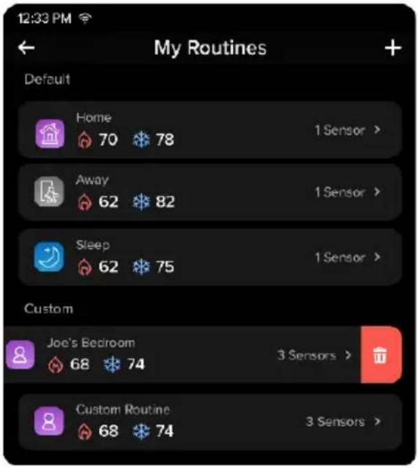
text_image
12:33 PM My Routines Default Home 70 78 1 Sensor > Away 62 82 1 Sensor > Sleep 62 75 1 Sensor > Custom Joe's Bedroom 68 74 3 Sensors > Custom Routine 68 74 3 Sensors >Use the My Routines screen to save temperature and thermostat preferences for different situations.
The thermostat comes with 3 preset routines—Home, Away, and Sleep—which you can customize according to your preferences. You can also create custom routines for different situations, such as for dinner or exercising.
Note: You can add up to 17 custom routines.
If you have individual room sensors (sold separately), you can choose which sensors are active during each routine. To buy official Levoit room sensors, contact Customer Support (see page 73).
You can use the schedule to automatically run routines (see Schedule, page 49).
BASIC FUNCTIONS (CONT.)
Usage
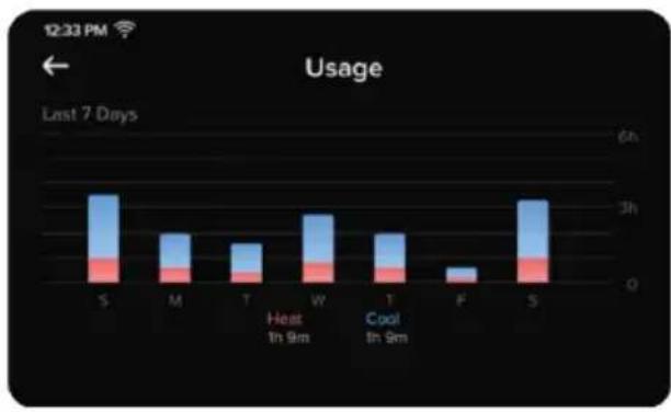
bar
Usage | Day | Heat (h) | Cool (h) | |---|---|---| | S | 1.5 | 0.8 | | M | 1.2 | 0.6 | | T | 1.1 | 0.5 | | W | 1.4 | 0.7 | | T | 1.3 | 0.6 | | F | 0.2 | 0.1 | | S | 1.6 | 0.9 |Use the Usage screen to view your heating and cooling usage over the past week.
BASIC FUNCTIONS (CONT.)
Vacation
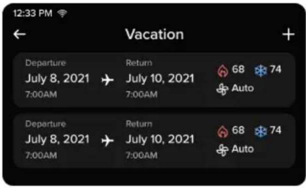
text_image
12:33 PM Vacation Departure July 8, 2021 7:00AM Return July 10, 2021 7:00AM 68 74 Auto Departure July 8, 2021 7:00AM Return July 10, 2021 7:00AM 68 74 AutoUse the Vacation screen to input your vacations, and set what the thermostat should do during those vacations. You can set departure and return dates, as well as a temperature range and fan setting for the thermostat to use.
BASIC FUNCTIONS (CONT.)
Sensors
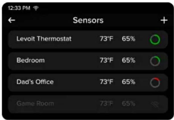
text_image
12:33 PM ← Sensors + Levoit Thermostat 73°F 65% Bedroom 73°F 65% Dad's Office 73°F 65% Game Room 73°F 65%Use the Sensors screen to view the thermostat sensor and additional sensors (sold separately). View the sensors' current temperature, humidity reading, online status, and remaining battery life. Room sensors can help eliminate hot and cold spots, prioritize certain rooms, and be used with routines.
Sensors must be paired to your thermostat through the VeSync app. Add the thermostat and room sensor to the same VeSync Home and the sensor will automatically pair with the thermostat.
To buy official Levoit room sensors, contact Customer Support (see page 73).
Note: To add and use additional room sensors, your thermostat must be connected to VeSync.
BASIC FUNCTIONS (CONT.)
Notifications
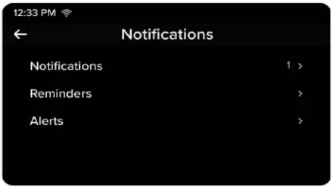
text_image
12:33 PM Notifications Notifications 1 > Reminders > Alerts >Use the Notifications screen to view any recent notifications, as well as set reminders and alerts.
You can set reminders for when to replace an air filter or perform HVAC maintenance. You can also choose to be alerted if there is a problem with your HVAC system or the temperature in your home exceeds a designated safe range.
Note: The default safe temperature range is a low of 35^ F and a high of 105^ F.
BASIC FUNCTIONS (CONT.)
Settings
| Date and Time | 1 min > |
| Hold Temperature | 2 hours > |
| Preferences | > |
| Lock | > |
| Advanced | > |
| Equipment | > |
| Safety Temperature | > |
| Reset | > |
| About | > |
Use the Settings screen to customize additional settings for your thermostat, such as screen brightness, temperature unit, display lock, and more.
BASIC FUNCTIONS (CONT.)
Advanced Settings
| 12:33 PM Advanced Settings | |
| Heat/Cool Minimum Delta | 8°F > |
| Fan Delay | 450 sec > |
| AC Settings | |
| Aux Settings | |
| Eco Level | |
| Sensor Calibration | |
| Temperature Offset | |
WARNING: Adjusting these setting without guidance may cause damage to your HVAC system. We recommend consulting a HVAC professional before adjusting advanced settings.
Use the Advanced Settings screen to fine-tune your thermostat settings. Follow on-screen instructions for more details.
BASIC FUNCTIONS (CONT.)
My VeSync
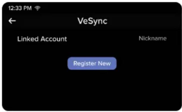
text_image
12:33 PM ← VeSync Linked Account Nickname Register NewUse the My VeSync screen to view your linked VeSync account information. You can also use this screen to register or re-register your thermostat if necessary.
VeSync App Setup
Note: The VeSync app is continually being improved and may change over time. If there are any differences, follow the in-app instructions.
- To download the VeSync app, scan the QR code or search "VeSync" in the Apple App Store® or Google Play Store.

text_image
QR code image containing encoded data, no visible human-readable text

Note: For Android™ users, choose "Allow" to use VeSync.
- Open the VeSync app. If you already have an account, tap Log In. To create a new account, tap Sign Up.
Note: You must create your own VeSync account to use third-party services and products. These will not work with a guest account. With a VeSync account, you can also allow your family and friends to control your smart thermostat.
-
Tap + and select your smart thermostat.
-
Follow the in-app instructions to set up your smart thermostat.
Note:
- You can change the name and icon at any time by going to the smart thermostat screen and tapping 🔒.
- You can use the VeSync app to connect your smart thermostat to Amazon Alexa or Google Assistant™.
Connect with Amazon Alexa or Google Assistant™
You can use the VeSync app to connect your smart thermostat to Amazon Alexa or Google Assistant™. Please follow the in-app instructions to set up your voice assistant.
Note: You must create your own VeSync account to access voice assistants.
VeSync App Functions
The VeSync app allows you to access additional smart thermostat functions, including those listed below. As the app develops, more features may become available.
Remote Control
- Control your thermostat from anywhere using the VeSync app.
- Connect your thermostat to third-party voice assistants.
Schedules
- Create and customize heating and cooling schedules for every day of the week.
Smart Scenes
- Prioritize comfort and air quality in your home using Smart Scenes, which can control your Levoit thermostat, humidifier, and air purifier settings all at the same time.
Energy Usage Graphs
- View your thermostat energy usage and how much time the thermostat spent heating/cooling.
• See your energy usage history for the previous week.
Troubleshooting
| Problem Possible Solution | |
| The thermostat display does not turn on. | Gently tug on each wire connected to the terminals on the backplate to make sure they are properly inserted and secure. |
| Make sure the cover of your HVAC system is completely closed. Some HVAC systems do not turn on if the cover is not closed. | |
| If you only have one R wire (R wires include R, Rc, and Rh), make sure the R wire is connected to the Rc terminal (see About R Wires, page 18). | |
| If you are using the PEK, make sure the wires are connected to the correct terminals on the backplate (see step 9 of Installing Thermostat without a C Wire, page 32). | |
| Use a multimeter to check the voltage of the C wire and Rc wire to make sure it is AC 18–30V. The thermostat does not work with high voltage systems. Contact Customer Support (see page 73). | |
| The thermostat freezes or crashes. | Remove the thermostat from the backplate, then reattach it. This will restart the thermostat. |
| Forgot lock screen password. Unlock the thermostat through the VeSync app. | |
| Heating and cooling functions are reversed. | If you have a heat pump system, change the O/B reversing valve setting in the thermostat's settings (see Settings, page 56). |
| Make sure that the W wire and Y wire are connected to the correct terminals on the backplate. | |
| If you are using the PEK, make sure the wires are connected to the correct terminals on the HVAC control board and backplate (see Installing Thermostat without a C Wire, page 22). | |
| The thermostat does not show weather information. | Make sure the thermostat is connected to the VeSync app. |
| In the VeSync app, make sure you input your home location and set the region to the United States. | |
| Room sensor (sold separately) does not connect to the thermostat. | Make sure the thermostat and room sensor are added to the same VeSync account. |
| One of the room sensor's batteries may be low.Replace with 2 AAA batteries. | |
If your problem is not listed, please contact Customer Support (see page 73).
VeSync App Troubleshooting
My smart thermostat isn't connecting to the VeSync app.
• Make sure your phone has Bluetooth ^® turned on and is not currently connected to another Bluetooth device.
- During the setup process, you must be on a secure 2.4GHz Wi-Fi® network. Confirm that the network is working correctly.
• Make sure the Wi-Fi password you entered is correct.
• There should be no spaces at the beginning or end of the password.
• Test the password by connecting a different electronic device to the router.
- If you're manually typing in the SSID and password, double check that both are entered correctly.
- Your phone should be as close as possible to your thermostat.
- Your router may need to be at a higher location, away from obstructions.
- Make sure your thermostat and router are away from appliances (such as microwave ovens, refrigerators, electronic devices, etc.) to avoid signal interference.
- If you're using a VPN, make sure it's turned off while setting up your thermostat.
- Disable portal authentication for your Wi-Fi network. If portal authentication is enabled, the thermostat will not be able to access your Wi-Fi network, and setup will fail.
Note: Portal authentication means that you need to sign in to your Wi-Fi network through a web page before you can use the Internet.
VESYNC APP TROUBLESHOOTING (CONT.)
My thermostat is offline.
• Make sure your router is connected to the internet and your phone's network connection is working.
- Delete your offline thermostat from the VeSync app. Swipe left (iOS®) or press and hold (Android"), then tap Delete Reconfigure the thermostat with the VeSync app.
Note: Power outages, internet outages, or changing Wi-Fi routers may cause the thermostat to go offline.
If your problem is not listed, please contact Customer Support (see page 73).
FEDERAL COMMUNICATION COMMISSION INTERFERENCE STATEMENT - PART 15
This device complies with Part 15 of the FCC Rules. Operation is subject to the following two conditions:
(1) This device may not cause harmful interference, and
(2) This device must accept any interference received, including interference that may cause undesired operation.
NOTE: This equipment has been tested and found to comply with the limits for a Class B digital device, pursuant to Part 15 of the FCC Rules. These limits are designed to provide reasonable protection against harmful interference in a residential installation. This equipment generates, uses and can radiate radio frequency energy and, if not installed and used in accordance with the instructions, may cause harmful interference to radio communications. However, there is no guarantee that interference will not occur in a particular installation. If this equipment does cause harmful interference to radio or television reception, which can be determined by turning the equipment off and on, the user is encouraged to try to correct the interference by one or more of the following measures:
- Reorient or relocate the receiving antenna.
- Increase the separation between the equipment and receiver.
- Connect the equipment into an outlet on a circuit different from that to which the receiver is connected.
- Consult the dealer or an experienced radio/TV technician for help.
FCC Caution: Any changes or modifications not expressly approved by the party responsible for compliance could void the user's authority to operate this equipment.
FCC RADIATION EXPOSURE STATEMENT
This equipment complies with FCC radiation exposure limits set forth for an uncontrolled environment. End users must follow the specific operating instructions for satisfying RF exposure compliance. To maintain compliance with FCC RF exposure compliance requirements, please follow operation instructions as documented in this manual. This transmitter must not be co-located or operating in conjunction with any other antenna or transmitter. This equipment should be installed and operated with a minimum distance of 20cm between the radiator and your body. The availability of some specific channels and/or operational frequency bands are country dependent and are firmware programmed at the factory to match the intended destination. The firmware setting is not accessible by the end user.
FCC SDOC SUPPLIER'S DECLARATION OF CONFORMITY
Arovast Corporation hereby declares that this equipment is in compliance with the FCC requirements. The declaration of conformity may be consulted in the support section of our website, accessible from www.levoit.com.
Warranty Information
| Product Name | AuraTM Smart Thermostat |
| Model | LTM-A401S-WUS |
| For your own reference, we strongly recommend that you record your order ID and date of purchase. | |
| Date of Purchase | |
| Order ID | |
Levoit Limited Product Warranty
Register your products at https://warranty.levoit.com/warranty to stay up to date with important product information such as product updates, limited warranties, usage and maintenance recommendations, and notifications concerning safety warnings or product recalls. Registration is not required to claim your limited warranty.
Two (2) Year Limited Consumer Product Warranty
Arovast Corporation ("Arovast") warrants that the product shall be free from defects in material and workmanship for a period of 2 years from the date of original purchase ("Limited Warranty Period"), provided the product was used
in accordance with its use and care instructions (e.g., in the intended environment and under normal circumstances).
Your Limited Warranty Benefits
During the Limited Warranty Period and subject to this limited Warranty Policy, Arovast will, in its sole and exclusive discretion, either (i) refund the purchase price if the purchase was made directly from the online Levoit store, (ii) repair any defects in material or workmanship, (iii) replace the product with another product of equal or greater value, or (iv) provide store credit in the amount of the purchase price.
Who is Covered?
This limited warranty extends only to the original consumer purchaser of the product and is not transferable to any subsequent owner of the product, regardless of whether the product transferred ownership during the specified term of the limited warranty. The original consumer purchaser must provide verification of the defect or malfunction and proof of the date of purchase to claim the Limited Warranty Benefits.
WARRANTY INFORMATION (CONT.)
Be Aware of Unauthorized Dealers or Sellers
This limited warranty does not extend to products purchased from unauthorized dealers or sellers. Arovast's limited warranty only extends to products purchased from authorized dealers or sellers that are subject to Arovast's quality controls and have agreed to follow its quality controls. Please be aware, products purchased from an unauthorized website or dealer may be counterfeit, used, defective, or may not be designed for use in your country. You can protect yourself and your products by making sure you only purchase from Arovast or its authorized dealers.
If you have any questions about a specific seller, or if you think you may have purchased your product from an unauthorized seller, please contact our Customer Support Team via support@levoit.com.
What's Not Covered?
- Normal wear and tear, including parts that might wear out over time (e.g., batteries, filters, cleaning brush, essential oil pads, etc.).
-
If the proof-of-purchase has been altered in any way or is made illegible.
-
If the model number, serial number or production date code on the product has been altered, removed or made illegible.
- If the product has been modified from its original condition.
- If the product has not been used in accordance with directions and instructions in the user manual.
- Damages caused by connecting peripherals, additional equipment or accessories other than those recommended in the user manual.
- Damages or defects caused by accident, abuse, misuse, or improper or inadequate maintenance.
- Damages or defects caused by service or repair of the product performed by an unauthorized service provider or by anyone other than Arovast.
- Damages or defects occurring during commercial use, rental use, or any use for which the product is not intended.
- If the unit has been damaged, including but not limited to damage by animals, lightning, abnormal voltage, fire, natural disaster, transportation, dishwasher, or water (unless the user manual expressly states that the product is dishwasher-safe).
WARRANTY INFORMATION (CONT.)
- Incidental and consequential damages.
- Damages or defects exceeding the cost of the product.
Claiming Your Limited Warranty Service in 5 Simple Steps:
- Make sure your product is within the specified limited warranty period.
- Make sure you have a copy of the invoice and order ID or proof-of-purchase.
- Make sure you have your product. DO NOT dispose of your product before contacting us.
- Contact our Customer Support Team via support@levoit.com
- Once our Customer Support Team has approved your request, please return the product with a copy of the invoice and order ID.
Sole and Exclusive Remedy
THE FOREGOING LIMITED WARRANTY CONSTITUTES AROVAST CORPORATION'S EXCLUSIVE LIABILITY, AND YOUR SOLE AND EXCLUSIVE REMEDY, FOR ANY BREACH OF ANY WARRANTY OR OTHER NONCONFORMITY OF THE PRODUCT COVERED BY THIS LIMITED PRODUCT WARRANTY STATEMENT. THIS LIMITED WARRANTY IS EXCLUSIVE, AND IN LIEU OF ALL OTHER WARRANTIES. NO EMPLOYEE OF AROVAST CORPORATION OR ANY OTHER PARTY IS AUTHORIZED TO MAKE ANY WARRANTY IN ADDITION TO THE LIMITED WARRANTY IN THIS LIMITED PRODUCT WARRANTY STATEMENT.
Disclaimer of Limited Warranties
TO THE FULLEST EXTENT PROVIDED BY APPLICABLE LAW, EXCEPT AS WARRANTED IN THIS LIMITED PRODUCT WARRANTY POLICY, AROVAST CORPORATION PROVIDES THE PRODUCTS YOU PURCHASE FROM AROVAST CORPORATION "AS IS" AND AROVAST CORPORATION HEREBY DISCLAIMS ALL WARRANTIES OF ANY KIND, WHETHER EXPRESS OR IMPLIED, STATUTORY, OR OTHERWISE, INCLUDING BUT NOT LIMITED TO ANY WARRANTIES OF MERCHANTABILITY, NON-INFRINGEMENT, AND FITNESS FOR PARTICULAR PURPOSE.
WARRANTY INFORMATION (CONT.)
Limitations of Liability
TO THE FULLEST EXTENT PROVIDED BY APPLICABLE LAW, IN NO EVENT WILL AROVAST CORPORATION, ITS AFFILIATES, OR THEIR LICENSORS, SERVICE PROVIDERS, EMPLOYEES, AGENTS, OFFICERS, OR DIRECTORS BE LIABLE FOR:
(a) DAMAGES OF ANY KIND ARISING OUT OF OR IN CONNECTION WITH PRODUCTS PURCHASED FROM AROVAST CORPORATION IN EXCESS OF THE PURCHASE PRICE PAID BY THE PURCHASER FOR SUCH PRODUCTS, OR
(b) INDIRECT, SPECIAL, INCIDENTAL, CONSEQUENTIAL, OR PUNITIVE DAMAGES EVEN IF AROVAST CORPORATION OR ONE OF ITS SUPPLIERS HAS BEEN ADVISED OF THE POSSIBILITY OR LIKELIHOOD OF SUCH DAMAGES.
AND REGARDLESS OF WHETHER CAUSED BY TORT (INCLUDING NEGLIGENCE), BREACH OF CONTRACT, OR OTHERWISE. OUR LIABILITY SHALL UNDER NO CIRCUMSTANCES EXCEED THE ACTUAL AMOUNT PAID BY YOU FOR THE DEFECTIVE PRODUCT, NOR SHALL WE UNDER ANY CIRCUMSTANCES BE LIABLE FOR ANY CONSEQUENTIAL, INCIDENTAL, SPECIAL OR PUNITIVE DAMAGES OR LOSSES, WHETHER DIRECT OR INDIRECT.
EXCEPT AS COVERED BY THIS LIMITED PRODUCT WARRANTY STATEMENT, AROVAST CORPORATION
SHALL NOT BE LIABLE FOR COSTS ASSOCIATED WITH THE REPLACEMENT OR REPAIR OF PRODUCTS PURCHASED FROM IT, INCLUDING, BUT NOT LIMITED TO, LABOR, INSTALLATION, OR OTHER COSTS INCURRED BY THE USER AND, IN PARTICULAR, ANY COSTS RELATING TO THE REMOVAL OR REPLACEMENT OF ANY PRODUCT.
OTHER RIGHTS YOU MAY HAVE
SOME JURISDICTIONS DO NOT ALLOW FOR: (1) EXCLUSION OF IMPLIED WARRANTIES; (2) LIMITATION ON THE DURATION OF IMPLIED WARRANTIES; AND/OR (3) EXCLUSION OR LIMITATION OF INCIDENTAL OR CONSEQUENTIAL DAMAGES; SO THE DISCLAIMERS IN THIS POLICY MAY NOT APPLY TO YOU. IN THESE JURISDICTIONS YOU HAVE ONLY THE IMPLIED WARRANTIES THAT ARE EXPRESSLY REQUIRED TO BE PROVIDED IN ACCORDANCE WITH APPLICABLE LAW. THE LIMITATIONS OF WARRANTIES, LIABILITY, AND REMEDIES APPLY TO THE MAXIMUM EXTENT PERMITTED BY LAW.
ALTHOUGH THIS LIMITED WARRANTY GIVES YOU SPECIFIC LEGAL RIGHTS, YOU MAY HAVE OTHER RIGHTS IN YOUR JURISDICTION. THIS STATEMENT OF LIMITED WARRANTY IS SUBJECT TO APPLICABLE LAWS THAT APPLY TO YOU AND THE PRODUCT. PLEASE REVIEW THE LAWS IN YOUR JURISDICTION TO UNDERSTAND YOUR RIGHTS FULLY.
WARRANTY INFORMATION (CONT.)
CHANGES TO THIS POLICY
We may change the terms and availability of this limited warranty at our discretion, but any changes will not be retroactive.
This warranty is made by:
Arovast Corporation
1202 N. Miller St., Suite A
Anaheim, CA 92806
Attributions
Amazon, Alexa, and all related logos are trademarks of Amazon.com, Inc. or its affiliates.
App Store ^® is a trademark of Apple Inc.
The Bluetooth® word mark and logos are registered trademarks owned by Bluetooth SIG, Inc. and any use of such marks by Arovast Corporation is under license. Other trademarks and trade names are those of their respective owners.
Google, Android, and Google Play are trademarks of Google LLC.
iOS is a registered trademark of Cisco Systems, Inc. and/or its affiliates in the United States and certain other countries.
Zigbee Alliance's trademarks and logos, and all goodwill associated therewith, are the exclusive property of the Zigbee Alliance.
Customer Support
If you have any questions or concerns about your new product, please contact our helpful Customer Support Team.
Arovast Corporation
1202 N. Miller St., Suite A Anaheim, CA 92806
Support Hours
Mon–Fri, 9:00 am–5:00 pm PST/PDT
Email: support@levoit.com
Toll-Free: (888) 726-8520
*Please have your order invoice and order ID ready before contacting Customer Support.
Notes
Notes
lěvoit™

/LEVOITLIFESTYLE

/LEVOIT

/LEVOIT

/LEVOIT

LEVOIT.COM