
226698 - Pizza oven Hendi - Free user manual and instructions
Find the device manual for free 226698 Hendi in PDF.


| Product Type | Electric Pizza Oven |
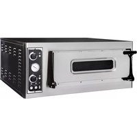
| Model | 226698 (BASIC 44G) |
| Brand | Hendi |
| Number of Chambers | 2 |
| Working Temperature Range | 50°C - 500°C |
| Power Supply | 400V 3-phase / 230V single-phase (configurable) |
| Total Power | 9.4 kW (at 400V) |
| Top Heating Element Power | 2350 W per chamber |
| Bottom Heating Element Power | 2350 W per chamber |
| External Dimensions (L x D x H) | 97.5 x 92.4 x 74.5 cm |
| Internal Dimensions (L x D x H) | 66.0 x 66.0 x 14.0 cm per chamber |
| Material | Stainless steel exterior, refractory stone baking surface |
| Control Panel | Thermostat knob (0-500°C), thermometer, warning lights, chamber light switch |
| Safety Features | RCD (30 mA) required, equipotential bonding, overvoltage category III |
| Cleaning | Refractory stone: brush when hot (350°C); exterior: soft cloth when cold |
| First Commissioning | Remove protective film; heat at 150°C for 1 hour, then 400°C for 1 hour |
| Warranty | 12 months (subject to use of original spare parts) |
| CE Marking | Yes (label on back) |
| Spare Parts Availability | Door handle, glass, gasket, lamp, thermostat, knob, thermometer, heating element, refractory stone, terminal box |
| Installation Requirements | Dry location, minimum 30 cm clearance from flammable materials, professional electrical connection |
Frequently Asked Questions - 226698 Hendi
User questions about 226698 Hendi
0 question about this device. Answer the ones you know or ask your own.
Ask a new question about this device
Download the instructions for your Pizza oven in PDF format for free! Find your manual 226698 - Hendi and take your electronic device back in hand. On this page are published all the documents necessary for the use of your device. 226698 by Hendi.
USER MANUAL 226698 Hendi
INSTRUCTIONS FOR USE AND MAINTENANCE
ELECTRIC OVENS FOR PIZZA BASIC 4/44G

natural_image
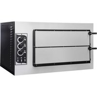
Exterior view of a two-tiered stainless steel electric oven with dual doors and control knobs (no visible text or labels)CE
ENGLISH

natural_image
Black triangular warning symbol with exclamation mark (no text or numbers)WARNING!
BEFORE SWITCHING ON THE OVEN: REMOVE THE POLYSTYRENE.
ATTENZIONE!
TOGLIERE IL POLISTIROLO PRIMA DI ACCENDERE.
ВНИМАНИЕ!
1- "CE" DECLARATION OF CONFORMITY AND MARKING
1.1- "CE" marking p. 5

2- GENERAL INFORMATION
2.1- The importance of the manual p. 5
2.2- Status of "turned off oven" p. 5
2.3- Warranty.... p. 5

3- TECHNICAL DESCRIPTIONS
3.1- Technical data p. 6
3.2- Destination of use p. 7
3.3- Limits of use.... p. 7
4- INSTALLATION
4.1- Instructions for the User p. 7
4.2- Electric connection ...... p. 8
4.3- Terminal box ...... p. 9
4.4- Equipotential p. 9

5- USE AND FUNCTIONING
5.1- Control panel p. 10
5.2- First commissioning p. 11
5.3- Turning on oven.... p. 11
5.4- Turning off oven p. 12

6- MAINTENANCE
6.1-Cleaning p. 12

7- DEMOLITION
7.1- General warnings p. 12
8- SPARE PARTS
8.1-Spare parts p. 13
8.2-Exploded view p.14

9- ELECTRIC EQUIPMENT
9.1- List of components.... p. 15
9.2-Wiring diagrams p. 16
CE ^1 —DECLARATION OF CONFORMITY AND MARKING
1.1- "CE" MARKING
The "CE" marking consists of a gray lable applied on the back of the oven.
The plate bears in readable and indelible way the following data:
- Name of the manufacturer; - Serial number ;
- CE marking; - Electric voltage and frequency (Volt/Hz);
- Model (MOD); - Year of construction ;
-Electric power (kW/A); - Weight of the oven; - "Made in Italy"

2—GENERAL INFORMATION
2.1- THE IMPORTANCE OF THE MANUAL
Before using the concerned oven, it is compulsory to read and understand this manual in all its parts.
This manual must always be available for the "authorized oepetators" and has to be placed and preserved colse to the oven.
The manufacturer declines all liability for eventual dmages to persons, animals, and things caused by the inobservance of the regulations described in this manual.
This manual is an integral part of the oven and must be preserved until its final dismantling.
The "authorized operators" must perform on the oven exclusively interventions for which they are specifically competent.
2.2- STATUS OF "TURNED OFF OVEN"
Before performing any type of maintenance and/or adjustment intervention, it is compulsory to disconnect the power supply source, disconnecting the power supply plug from the mains outlet verifying that the oven is effectively turned off and cooled.
2.3- WARRANTY
The manufacturer warrants that the concerned ovens are tested at manufacturer's premises. The warranty of the oven is of 12 (twelve) months.

THE TAMPERING AND/OR REPLACEMENT OF PARTS WITH NON ORIGINAL SPARE PARTS CAUSE THE DECAY OF THE WARRANTY AND RELEASE THE MANUFACTURER FROM ANY LIABILITY.
3.1 TECHNICAL DATA
| BASIC 4G | BASIC 44G | |||
| Temperatura d'esercizio | Working temperatureArbeitstemperatur | Temperature de travail | °C | 50 | 500 | 50 | 500 | |
| Temperatura de ejercicio | Temperatura de funcionamentoРабочая температура | ||||
| Alimentazione | Power supply | SpannunAlimentation | Alimentación | Alimentação | Питание | volt | 230 | 400 | 230 | 400 | |
| Camere | Chamber | Kammer | ChambreCámaras | Câmaras | Рабочая камера | n° | 1 | 2 | |
| Potenza | Power | Heizleistung | PuissancePotencia | Potência | Мощность | kW | 4,7 | 9,4 | |
| Potenza resistenza cielo | Power of top heating elementOben widerstandsleistungspitze | W | 2350x1 | 2350x2 | |
| Puissance resistance plafond | Potencia resistencia techo | ||||
| Potência da resistência superior | Мощность верхних ТЭНов | ||||
| Potenza resistenza platea | Power of bottom heating element WUnten widerstandsleistungspitze | 2350x1 | 2350x2 | ||
| Puissance resistance sol | Potencia resistencia solera | ||||
| Potência da resistência inferior | Мощность нижних ТЭНов | ||||
| Dimensioni esterne | External dim. | Außenabmessungen cm | L 97,5 | L 97,5 | ||
| Dim. extérieures | Medidas externas | P 92,4 | P 92,4 | ||
| Dimensões externas | Внешние габ. Размеры | H 41,3 | H 74,5 | ||
| Dimensioni interne | Inside dim. | Innenabmessungen | cm | L 66,0 | L 66,0 | |
| Dim. intérieures | Medidas internas | P 66,0 | P 66,0 | ||
| Dimensões internas | Внутренние размеры | H 14,0 | H 14,0 | ||
3.2- DESTINATION OF USE
The foreseen use for which this oven has been designed and produced is the following

FORESEEN USE: PIZZA BAKING, GRATINATING OF GASTRONOMY PRODUCTS AND HEATING OF FOODSTUFF IN BAKING PANS.

THE OVEN CAN BE USED EXCLUSIVELY BY AN AUTHORIZED OPERATOR (USER).

THIS APPLIANCE IS NOT INTENDED FOR USE BY PERSONS (INCLUDING CHILDREN) WITH REDUCED PHYSICAL, SENSORY OR MENTAL CAPABILITIES, OR LACK OF EXPERIENCE AND KNOWLEDGE, UNLESS THEY HAVE BEEN GIVEN SUPERVISION OR INSTRUCTION CONCERNING USE OF THE APPLIANCE BY A PERSON RESPONSIBLE FOR THEIR SAFETY.

CHILDREN SHOULD BE SUPERVISED TO ENSURE THAT THEY DO NOT PLAY WITH THE APPLIANCE
3.3- LIMITS OF USE
This oven has been designed and manufactured exclusively for the destination of use described in Par. 3.3, therefore, any other type of use is strictly forbidden in order to assure, at any time, the safety of the authorized operators, as well as the efficiency of the oven itself.

4—INSTALLATION
4.1- INSTRUCTIONS FOR THE USER
The place where the oven is installed must have the following environmental characteristics:
- To be dry;
• Water sources at safe distance;
- Adequate ventilation and lighting corresponding to hygiene and security rules following the existing laws.

THE OVEN MUST NOT BE INSTELLED IN PROXIMITY OF THE INFLAMMABLE MATERIALS (WOODS, PLASTIC, COMBUSTIBLE, GAS, ETC.). AVOID THE CONTACT OF INFLAMMABLE OBJECTS WITH THE HOT SURFACES OF THE OVEN. ALWAYS ASSURE THE SAFETY FIREPROOF CONDITIONS. MAINTAIN A FREE SPACE AROUND THE OVEN OF AT LEAST 30 CM.
Verify that the electrical set-up corresponds with the numbers of the technical characteristics (Par. 3.1), and on the small plate at the back of the oven. The characteristics of the electric socket must be compatible with the plug installed on the cable.
4.2- ELECTRIC CONNECTION

THE ELECTRIC CONNECTION OF THE OVEN TO THE MAINS MUST BE COMPULSORILY AND EXCLUSIVELY PERFORMED BY AN AUTHORIZED TECHNICIAN (ELECTRICIAN) SATISFYING THE TECHNICAL AND PROFESSIONAL REQUIREMENTS STATED BY THE REGULATIONS IN FORCE IN THE COUNTRY OF USE OF THE OVEN, WHO MUST ISSUE A DECLARATION OF CONFORMITY FOR THE INTERVENTION PERFORMED.

FOR DIRECT CONNECTION TO THE NETWORK, YOU MUST HAVE A DEVICE THAT HAS A CONTACT GAP TO ENSURE THE COMPLETE DISCONNECTION, IN THE CONDITIONS OF OVERVOLTAGE CATEGORY III, IN ACCORDANCE WITH THE RULES FOR INSTALLATION.
To connect the machine to the electric network it is necessary to proceed as follows:
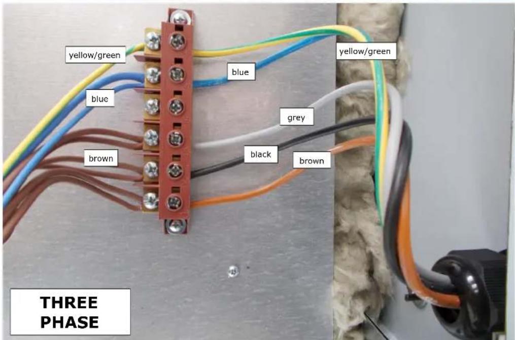
1) connect to the wires to the terminals L1—L2—L3—N — ± of power cord type H07RNF 3G X "x" mm² unsheathed with ferule;
2) put together the other end of the cable and a plug, which is normalised and polarised (the distinction between phase and neutral must be unequivocal.
3) to connect the oven to 230 V single phase is sufficient to make a bridge between L1-L2-L3 with the special plates present in the terminal box
| L1 | Clamp N.1 |
| L2 | Clamp N.2 |
| L3 | Clamp N. 3 |
| N | Clamp N. 5 |
| ± | Clamp N. 6 |

ONCE THE ELECTRIC CONNECTION HAS BEEN PERFORMED, THE AUTHORIZED TECHNICIAN (ELECTRICIAN) MUST ISSUE A DECLARATION CERTIFYING THE MEASUREMENT OF THE CONTINUITY OF THE EQUIPOTENTIAL PROTECTION CIRCUIT.

THE APPLIANCE IS TO BE SUPPLIED THROUGH A RESIBASIC CURRENT DEVICE (RCD) HAVING A RATED RESIBASIC OPERATING CURRENT NOT EXCEEDING 30 MA
4.3- TERMINAL
La terminal is placed internally of the oven.

PIC. A
PIC. B
| Oven type N. of cables Section (mm ^2 ) | ||
| Single phase, one chamber 3 4 | ||
| Single phase, two chambers and versions 9 single phase 3 6 | ||
| Three phase one chamber and two chambers 5 4 | ||
| Three phase from versions 9 and up 5 6 |
4.4- EQUIPOTENTIAL
The equipment must be connected with an equi-potential system. The connection terminal is located near the supply cable entry. The bonding wire must have a minimal section of 10 mm^2 .
5.1- CONTROL PANEL
The control panel is installed on the front side of the oven as shown below:

PIC.1 Control panel
| LEGEND PIC.1 | ||
| REF. | DENOMINATION FUNCTION | |
| 1 | Warning light | If lighted, it signals the operation of the resistor in use. |
| 2 | Thermostat | Pos.0:it disables the operation of the resistor;Pos. 0-500°C :it enables the operation of the resistor and sets the wished temperature. |
| 3 | Thermometer Indicates the temperature in the baking chamber. | |
| 5 | Chamber lamp switch | Pos. I: It switches on the light in the oven chamber;Pos. 0: It switches off the light in the oven chamber. |
5.2- FIRST COMMISSIONING
Before the ignition of the oven remove the protective film without using tools that can damage the surfaces.

DESPITE THE THERMAL POTENTIALITIES OFFERED BY THE OVEN, FOR SAFETY PURPOSE THE MAXIMUM ALLOWED TEMPERATURE IS 500°C AND CAN BE SELECTED BY MEANS OF THE TIMERS.

THE COMMISSIONING OF THE OVEN CAN BE PERFORMED ONLY WHEN THE INSTALLATION HAS BEEN COMPLETED AND THE AUTHORIZED TECHNICIANS HAVE ISSUED THE DECLARATION OF CONFORMITY FOR THE ELECTRIC CONNECTION.
The first commissioning must be performed proceeding as follows:
1) Clean the front part of the oven with a clean and soft cloth in order to remove any eventual residues;
2) Connect the plug of the power supply cable to the power supply outlet;
3) Enable the operation of the resistors setting the thermostats (PIC.1 - Ref.2) on the temperature of 150^ C indicated on the handle. The related warning lights signaling the operation of the resistors in use (PIC.1 - Ref.1) will switch on;
4) Let the oven operate for about 1 h;
5) Disable the operation of the resistors setting the thermostats (PIC.1 - Ref.2) to position "0" and their warning light will turn off;
6) Open the door of the oven for about 15 min in order to let eventual vapors and smells be discharged;
7) Close the door and repeat the process described in Section 4) bringing the thermostat (PIC.1 - Ref.2) at the temperature of 400^ indicated on the control panel;
8) Let the oven work for about 1 h;
9) Disable the operation of the resistors bringing the thermostats (PIC.1 - Ref.2) to pos. "0"; their warning light will turn off;
11) Turn off the oven as described in par.5.4.
1) Connect the plug of the power supply cable to the power supply outlet;
2) Enable the operation of the resistors bringing the thermostats (PIC.1 - Ref.2) to the wished temperature. The related warning lights (PIC.1 - Ref.1) signaling the operation of the resistors in use will switch on;
3) Once the oven has reached the wished temperature (see point 9 of this paragraph), visible on the thermometer (PIC.1 - Ref.3) it is possible to insert the pizza in the oven for the backing;
4) Open the oven door manually using the suitable handles;
5) To light the inside part of the backing chamber, press the oven lamp switch (PIC.1 - Ref.5);
6) Insert in the oven the pizza and/or the pizzas to be backed using suitable devices for this aim. It is important to avoid to leave the door open for too long, since the outgoing heat lowers the temperature of the oven.
7) Close the door again and check the backing through the inspection glass;
8) The baking temperature of the pizza varies if it is positioned directly on the refractory stone or on a baking pan. In the first case, it is suggested to set the backing temperature at 280^ C for the bottom and 320^ C for the crown; on the contrary, in the second case, set 320^ C for the bottom and 280^ C for the crown;
9) When the baking haa ended, open the door and extract the pizza ond/or the pizzas and colse the door again.
Once the use of the oven has ended, proceed as follows:
Turning off the oven bringing the knobs that regulate the thermostats in pos."0" (PIC.1 - Ref.2);

6- MAINTENANCE

BEFORE PERFORMING ANY TYPE OF MAINTENANCE INTERVENTION, IT IS COMPULSORY TO DISCONNECT THE PLUG OF THE OVEN FROM THE POWER SUPPLY OUTLET.
6.1-CLEANING
The clearing must be done every time the oven has been used following all the rules to prevent malfunctioning of the oven and for hygienic purpose.
Cleaning of the refractory surface: this operation has to be performed with hot oven.
Once the temperature of about 350^ C has been reached, turn off the oven, open the door and clean the surface using a brush in vegetable fiber equipped with a long handle in order to avoid the contact with the oven hot parts.
External clearing of the oven: (surfaces in stainless steel, inspection glass and control panel): this operation has to be performed with cold oven.

IT IS RECOMMENDED TO THE OPERATOR IN CHARGE TO USE PROPER GLOVES AND SUITABLE CLOTHING TO AVOID BURNINGS.

IT IS FORBIDDEN TO USE THROWS OR DRIPS OF WATER, ABRASIVE OR CORROSIVE SUBSTANCES, AND ANYTHING ELSE THAT CAN DAMAGE THE COMPONENTS, COMPROMISE THE SAFETY, AND BE DANGEROUS FROM AN HYGIENIC POINT OF VIEW.
For any intervention of supplementary maintenance, repairing and/or replacement refer exclusively to the authorized dealer where the oven has been purchased and/or to an authorized technician satisfying the technical and professional requirements stated by the regulations in force.

7- DEMOLITION
7.1- GENERAL WORNINGS
When dismantling the oven, compulsorily observe the provisions of the regulations in force. Differentiate the parts making up the oven according to different types of construction materials (plastic, copper, iron, etc.).
8.1 - SPARE PARTS
| DESCRIPTION | BASIC 4G | BASIC 44G | |
| 1/A Door Handle 5M200030 5M200030 | |||
| 1/B Small lateral door handles - - | |||
| 5 Door Glass 5V010015 5V010015 | |||
| 6 Door glass gasket 5G100001 5G100001 | |||
| 25 Lamp holder 5P110003 5P110003 | |||
| 26 | Lamp glass | 5V010003 | 5V010003 |
| 27 | Lamp | 5L020005 | 5L020005 |
| 30 | Thermostat | 5T010001 | 5T010001 |
| 31 | Thermostat knob | 5M200003 | 5M200003 |
| 34 Thermometer 5T010200 5T010200 | |||
| 35 | Heating element's warning light | 5L020017 | 5L020017 |
| 36 | Heating element's switch | - | - |
| 37 | Chamber light switch | 5I100017 | 5I100017 |
| 38 | Heating element | 5R050220 | 5R050220 |
| 39 Refractory stone 5P050010 5P050010 | |||
| 41 | Terminal box | 5M100010 | 5M100010 |
8.3-EXPLODED VIEW:
MOD. BASIC

9.1 LIST OF COMPONENTS
| MARK DESCRIPTION | |
| T Single (1) pole thermostat | |
| TT Three (3) poles thermostat | |
| QS0 Heating elements on/off switch | |
| HL Heating elements spy light | |
| QF0/1 Chamber light on/off switch | |
| K Contactor | |
| TI Timer | |
WIRING DIAGRAM
BASIC 4G / 44G
400V
3 PHASE
(one coocking chamber)

Legend of oven wiring diagrams
T
unipolar thermostat;
QSO
heating element power switch;
HL
heating elements spy light;
QF0
chamber light on/off switch;

- INSTRUCTIONS FOR USE AND MAINTENANCE
- ELECTRIC OVENS FOR PIZZA BASIC 4/44G
- 1- "CE" DECLARATION OF CONFORMITY AND MARKING
- 2- GENERAL INFORMATION
- 3- TECHNICAL DESCRIPTIONS
- 4- INSTALLATION
- 5- USE AND FUNCTIONING
- 6- MAINTENANCE
- 7- DEMOLITION
- 8- SPARE PARTS
- 9- ELECTRIC EQUIPMENT
- CE 1 —DECLARATION OF CONFORMITY AND MARKING
- 1.1- "CE" MARKING
- 2—GENERAL INFORMATION
- 2.1- THE IMPORTANCE OF THE MANUAL
- 2.2- STATUS OF "TURNED OFF OVEN"
- 2.3- WARRANTY
- 3.2- DESTINATION OF USE
- 3.3- LIMITS OF USE
- 4—INSTALLATION
- 4.1- INSTRUCTIONS FOR THE USER
- 4.2- ELECTRIC CONNECTION
- 4.3- TERMINAL
- 4.4- EQUIPOTENTIAL
- 5.1- CONTROL PANEL
- 5.2- FIRST COMMISSIONING
- 6.1-CLEANING
- 7.1- GENERAL WORNINGS
- 8.3-EXPLODED VIEW:
- LIST OF COMPONENTS
Brand : Hendi
Model : 226698
Category : Pizza oven