
HW86 - Uncategorized Newline - Free user manual and instructions
Find the device manual for free HW86 Newline in PDF.


| Product Type | Interactive Display |
| Brand | Newline |
| Model | HW86 |
| Screen Size | 86 inches |
| Resolution | 4K UHD (3840 x 2160) - typical |
| Touch Technology | Infrared (20 touch points) - typical |
| Audio | Built-in speakers (2 x 10W) - typical |
| Connectivity | HDMI, USB, VGA, etc. (typical) |
| Power Supply | AC 100-240V, 50/60Hz (typical) |
| Power Consumption | < 400W (typical) |
| VESA Mount Pattern | 800 x 600 mm (typical for 86") |
| Compatible Cart Model | WH3310 |
| Cart Compatibility | 55 - 86 inch displays |
| Cart Maximum Load | 100 kg |
| Cart Wheels | 4 x 4 inch wheels with brake |
| Cart Mounting Bracket | Wall plate and adjustable brackets |
| Cart Installation | Wall-mounted or cart-mounted |
| Included Fasteners | M8 and M6 screws, washers, spring washers |
| Included Tools | Cross screwdriver, spanner |
| Documentation | 6-page installation manual (PDF) |
Frequently Asked Questions - HW86 Newline
User questions about HW86 Newline
0 question about this device. Answer the ones you know or ask your own.
Ask a new question about this device
Download the instructions for your Uncategorized in PDF format for free! Find your manual HW86 - Newline and take your electronic device back in hand. On this page are published all the documents necessary for the use of your device. HW86 by Newline.
USER MANUAL HW86 Newline
WH3310 Installation Manual

natural_image
Technical line drawing of a mechanical support structure with wheels and railings (no text or symbols)Model: WH3310
To use the product safely and correctly, please read this manual carefully before installation.
This product is suitable for 55-86 inch interactive display.
The maximum capacity of this cart is 100 Kg.
- Main Parts:

natural_image
Line drawing of a three-legged support structure (no text or symbols)A-left column 1pc

natural_image
Technical line drawing of a vertical support structure with three legs (no text or symbols)B-right column 1pc

natural_image
Pure technical line drawing of a structural frame with no text, numbers, or symbolsD-wall plate 1pc

E-bracket 2pcs

C-tray 1pc

F-4 inch wheels 4pcs
- Spare parts
 |  | 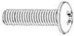 |  |
| a-M8*20 Screw12pcs | b-M6*16 Screw4pcs | c-M8*25 Screw4pcs | d-φ16*8.5*1.0 Washer4pcs |
 | 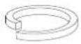 |  |  |
| e-Φ24*12.5*1.5 Washer 4pcs | f- Φ 20*12. 5*3. 5 Spring washer 4pcs | Cross screwdriver 1pc | Spanner 1pc |
Step 1:
Adjust the wheels to the braking state, and then screw the four wheels onto the left and right columns. (Figure 1)

Figure 1
Step 2:
There are 3 combinations of installation holes in the wall plate. Choose the combination you need. Turn a screw (a) into the lower hole of the combination in advance. Do not lock it and reserve a distance of 8mm. Then hang up the wall plate and lock all six screws (a).

Figure 2
Step 3:
Turn a screw (a) into the hole as shown in Figure 3 in advance, do not lock and reserve a distance of 8mm. Then hang up the tray and lock all six screws (a).

Step 4:
As shown in Figure 4, lay the conference screen flat, and select the appropriate screw to connect the bracket with the screen.

Figure 4
Warm Tips:
When selecting the bottom group of holes on the column, the distance from the bottom group of holes on the bracket to the tray is shown as the figure below. Please pay attention to the size of your screen and ensure that the lower end of the screen does not interfere with the tray.

Step 5:
Install the interactive display with the bracket on the wall plate, ensure that the hook is hung on the border of the wall plate, and then lock the safety screw on the bracket.

natural_image
Technical line drawings of a metal frame structure with mounting base and support legs, showing structural changes (no text or symbols)Figure 5
Step 6:
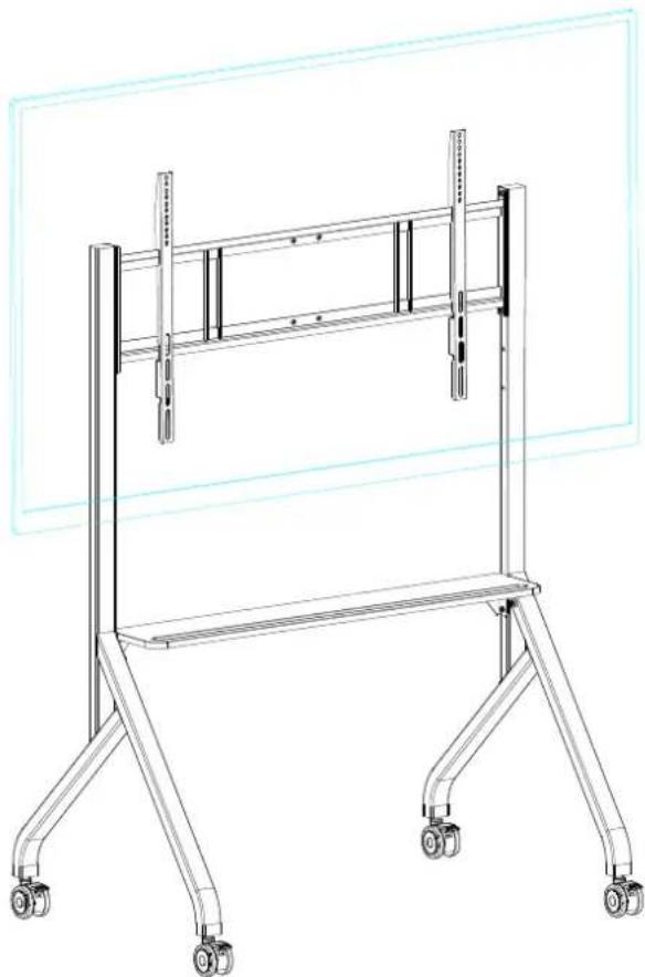
The effect after installation is as following
natural_image
Technical line drawing of a mechanical support frame with wheels and vertical supports (no text or symbols)Figure 6
Brand : Newline
Model : HW86
Category : Uncategorized