
ERS S40-400 - Heat pump Nibe - Free user manual and instructions
Find the device manual for free ERS S40-400 Nibe in PDF.


| Product Type | Exhaust Air Heat Recovery Unit (HRV) / Heat Pump |
| Model | ERS S40-400 |
| Brand | Nibe |
| Dimensions (W x H x D) | 600 mm x 600 mm x 620 mm |
| Weight | 45 kg |
| Power Supply | 230 V ~ 50 Hz, 10 A |
| Power Consumption | Re-heater: 1000 W; Fan drive: 2 x 90 W |
| Enclosure Class | IP X1 |
| Duct Connections | 4 x Ø160 mm (exhaust, extract, supply, outdoor air) |
| Filter Types | Coarse 65% (exhaust), ePM1 55% (supply) |
| Sound Power Level (LWA) | 51 dB(A) |
| Sound Pressure at 1 m | 40 dB(A) |
| Temperature Efficiency | Up to 84.5% (at 25% RPM, 7°C outdoor, 20°C indoor) |
| Humidity Efficiency | Up to 95% (same conditions) |
| Energy Efficiency Class | A (RVU bidirectional) |
| Specific Energy Consumption (SEC) | Average: -37.9 kWh/m²year (cold: -74.8, warm: -14.2) |
| Maximum Airflow | 460 m³/h (at 50 Pa) |
| Heat Recovery Type | Rotary heat exchanger (regenerative) |
| Control Features | Demand-controlled ventilation (humidity), scheduling, night cooling, defrost |
| Mounting Options | Wall-mounted (bracket included) or floor-standing (feet included) |
| Conversion | Left-handed (default) to right-handed possible |
| Compatible Main Products | S1155, S1255, VVM S325, SMO S40, VVM S320 |
| Supply Cable Length | 2.4 m (communication cable also 2.4 m) |
| Maintenance | Replace filters (coarse and ePM1) every 1-24 months (set in menu) |
Frequently Asked Questions - ERS S40-400 Nibe
User questions about ERS S40-400 Nibe
0 question about this device. Answer the ones you know or ask your own.
Ask a new question about this device
Download the instructions for your Heat pump in PDF format for free! Find your manual ERS S40-400 - Nibe and take your electronic device back in hand. On this page are published all the documents necessary for the use of your device. ERS S40-400 by Nibe.
USER MANUAL ERS S40-400 Nibe
natural_image
Illustration of a rectangular industrial container with four coiled pipes on top (no text or symbols)
natural_image
Blue line icon of a wrench inside a hexagon (no text or symbols)Table of Contents
____
____
____ ____
(No text)
____ ____
____ ____
____
____
(No text)
____ ____
(No text)
(No text)
(No text)
(No text to output)
____ ____
____ ____
(No text)
____ ____
The Ground Truth image displays a single, solid horizontal line. According to Rule 2 (UNDERSCORE & LINE RULES), if the GT contains lines used for stylistic emphasis or as background (like ruled paper), the OCR result must ignore them. The provided OCR content is "____", which consists of four underscores. This is incorrect because underscores are not equivalent to a solid line and are not permitted under the “Stylistic/Background Lines (Ignore)” rule. Outputting underscores for a stylistic line is incorrect because it misinterprets the line as a fill-in-the-blank placeholder. Therefore, the OCR result is inconsistent with the Ground Truth.
____
____
(No text)
41 Important information 239 Acces
4Safety information
4Symbols 2410 Techn
4Serial number 24Dimension
5Recovery 25Technical
6Inspection of the installation 26Energy Ial
27Electrical
72 Delivery and handling
7Transport and storage 29Item reg
7Supplied components 31Contact
7Compatible products ____ 3Contact
7Removing the covers
8Physical conguration 11Assembly
11Mounting
123 Design of the HRV unit
13Pipe connections
13Sensors etc.
13 Electrical components
13Ventilation
13Miscellaneous
144 Ventilation connections
14General ventilation connections
14Ventilation ow
14Adjusting ventilation
14Ventilation connections
155 Electrical connection
150verview, AJB board (AA33)
15Supply
15Connecting to main product
186 Commissioning and adjusting
18Preparations
18Start-up and inspection
197 Activating ERS S40
19Start guide
19Menu system
228 Disturbances in comfort
22Troubleshooting
Important information
Safety information
Serial number
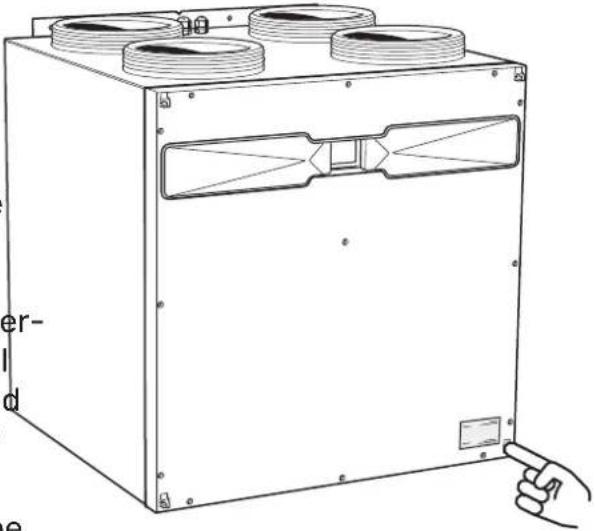
This manual describes installation and service procedures The serial number can be found at the bottom right, inside for implementation by specialists. the front cover.
The manual must be left with the customer.
This appliance can be used by children aged from 8 years and above and persons with reduced physical, sensory or mental capabilities or lack of experience and knowledge if they have been given supervision or instruction concerning use of the appliance in a safe way and understand the hazards involved. Children shall not play with the appliance. Cleaning and user maintenance shall not be made by children without supervision.
This is an original manual. It may not be translated without the approval of NIBE.
Rights to make any design or technical modifications are reserved.
©NIBE 2023.
natural_image
Line drawing of a rectangular industrial machine with four circular components and a hand pointing to a small component (no text or symbols present)
Caution
You need the product's serial number for servicing and support.
If the supply cable is damaged, only NIBE, its service representative or similar authorised person may replace it to prevent any danger and damage.
Symbols
Explanation of symbols that may be present in this manual.

NOTE
This symbol indicates danger to person or machine.

Caution
This symbol indicates important information about what you should consider when installing or servicing the installation.
Recovery
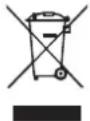
Leave the disposal of the packaging to the installer who installed the product or to special waste stations.
When disposing of the product, its constituent materials and components, e.g. compressors, fans, circulation pumps and circuit boards, must be disposed of at a special waste station or dealer who provides this type of service.
To access the separate components, refer to the section that shows the construction of the product. No special tools are required for access.
Improper disposal of the product by the user results in administrative penalties in accordance with current legislation.
Inspection of the installation
Current regulations require the heating installation to be inspected before it is commissioned. The inspection must be carried out by a suitably qualified person. In addition, II in the page for the installation data in the User Manual.
| √ | DateSignatu | |||
| Electricity (page 15) | ||||
| Connections | ||||
| Main voltage | ||||
| Fuses property | ||||
| Earth circuit-breaker | ||||
Delivery and handling
Transport and storage
ERS S40 should be transported and stored in the dry.
Supplied components

Rail for wall mounting

4 x feet

2 x screws
Compatible products
S1155
S1255
- VVM S325
• SMO S40• VVM S320
INNER FRONT COVER
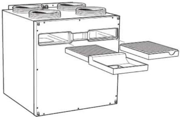
The inner front cover must be removed to access the internal parts.
- Remove the air Iters.
natural_image
Technical line drawing of a mechanical device with multiple ports and internal compartments (no text or symbols)- Loosen the screws that hold the inner front cover in place.
Removing the covers
FRONT COVER
- Pull the hatch towards yourself.

natural_image
Line drawing of a rectangular industrial cabinet with three circular tanks and a black arrow indicating direction (no text or symbols)
natural_image
Technical line drawing of a mechanical housing or enclosure with mounting flanges and a directional arrow (no text or symbols)- Pull the front cover straight out.
Physical conguration
ERS S40 is supplied with exhaust air and supply air to the left, known as the left-handed version. The images in this manual show ERS S40 in the left-handed version, unless otherwise specified.

ERS S40 can be converted to a right-handed version if necessary, which means that exhaust air and supply air are connected to the right. 3.

CONVERSION TO RIGHT-HANDED VERSION
- Remove the insulation located in the right-hand space.

natural_image
Technical line drawing of a mechanical housing or enclosure with four circular components and an arrow indicating direction (no text or symbols present)- Remove the humidity sensor (BM20) including the insulation plug. This is located furthest in the left-hand space.

natural_image
Technical diagram of an indoor air duct system with pipe fittings and ventilation ducts (no text or labels)- Remove the extract air sensor (BT21) including the insulation plug. This is located furthest in the right-hand space.

natural_image
Technical line drawing of an indoor air conditioning unit with circular vented dividers and internal components (no text or symbols)- Disconnect the two cables located in the re-heater.

natural_image
Technical diagram of an air conditioning unit showing internal components and wiring (no text or labels)- Remove the re-heater (EB18).

natural_image
Technical line drawing of an air conditioning unit with fans and a central fan assembly (no text or symbols)- Install the re-heater (EB18) furthest in the right-hand space.

natural_image
Technical line drawing of an air conditioner unit with cable routing and a power adapter (no text or symbols)- Ret the insulation.

natural_image
Technical line drawing of a mechanical or electrical enclosure with multiple circular components and internal wiring (no text or symbols)- Connect the two cables to the re-heater.

natural_image
Technical line drawing of an industrial HVAC unit with internal components and wiring (no text or symbols)- Install the humidity sensor (BM20) and the insulation 11. Install the insulation plug and sensor (BT21) furthest in plug in the right-hand space. the left-hand section.
There is a cable tie on the sensor, indicating how far in the sensor has to be positioned.

natural_image
Technical line drawing of a mechanical or electrical enclosure with circular components and internal wiring, showing internal structure and component layout (no text or symbols)- Dismantle the grating.

natural_image
Technical line drawing of an industrial air conditioning unit with multiple rings and a central cooling unit (no text or symbols)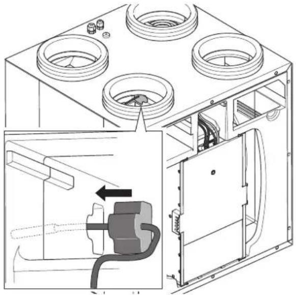
natural_image
Technical line drawing of a mechanical device with multiple circular components and internal wiring (no text or symbols)-
Ret the grating.
-
Switch the Iters around. Filter ePM1 55% must be placed on the supply air side.
-
Fit the Iter cassettes.
-
Mark the change to the air ows on the duct connection plate (PZ4) on the upper side of the product.

Caution
In order to complete the conversion, changes are required in menu 7.2.11.
Assembly
Mounting
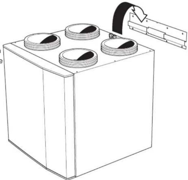
ERS S40 can be installed on a wall or placed on a horizontal hanging on a wooden wall, a vibration damper is resurface. For wall installation, place the enclosed rail on recommended to prevent vibration being transferred.
solid wall. Noise from the fans might be transferred to the 1. Install the enclosed bracket to the wall.
rail. When placing on a horizontal surface, t the enclosed feet on the underside of ERS S40. It is important for the surface where ERS S40 is placed to be stable and to withstand the weight of the unit.
• Install with its back to an outside wall, ideally in a room where noise does not matter, in order to eliminate noise problems. If this is not possible, avoid placing it against a wall behind a bedroom or other room where noise may be a problem.
- Wherever the unit is located, walls to sound sensitive rooms should be tted with sound insulation.
- The HRV unit's installation area always has to have a temperature of at least -38 °C and max. 50 °C.
INSTALLATION AREA
Leave a free space of 800 mm in front of the product.


NOTE
Ensure that there is sucient space (300 mm) for connecting ventilation ducts.
natural_image
Line drawing of a rectangular industrial machine with four circular components and a curved pipe attached to the top (no text or symbols)- Screw ERS S40 rmly into place on the bracket, using the enclosed screws.

natural_image
Line drawing of a rectangular industrial or electrical unit with four circular components mounted on top, no text or symbols present.Design of the HRV unit
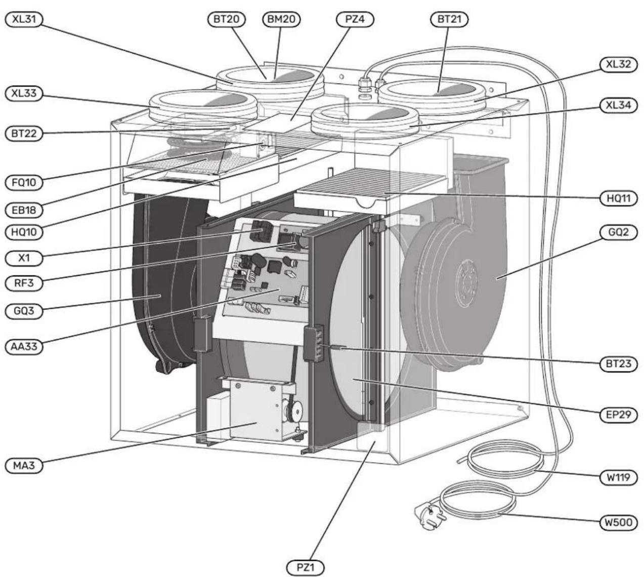
Pipe connections
Ventilation connection, exhaust airXL31
Ventilation connection, extract airXL32
Ventilation connection, supply airXL33
Ventilation connection, outdoor airXL34
Sensors etc.
Humidity sensor, exhaust airBM20
Temperature sensor, exhaust airBT20
Temperature sensor, extract airBT21
Temperature sensor, supply airBT22
Temperature sensor, outdoor airBT23
Electrical components
AJBboardAA33
Re-heaterEB18
Temperature limiterFQ10
Motor for the heat exchangerMA3
EMC cardRF3
W119 Communication cable
W500 Cord with connection plug
X1 Terminal block, power supply
Ventilation
EP29 Rotary heat exchanger
GQ2 Exhaust air fan
GQ3 Supply air fan
HQ10 Exhaust air Iter
HQ11 Supply air Iter
Miscellaneous
PZ1 Type plate
PZ4 Duct connection rating plate
Designations according to standard EN 81346-2.
Ventilation connections
General ventilation connections
The ventilation flow must comply with the applicable national standards.
- Ventilation installation must be carried out in accordance with current norms and directives.
The supply air ow must be lower than the exhaust air ow to prevent over pressure in the house.
- Provision must be made for inspection and cleaning of the duct.
Set the ventilation capacity in the main product's menu system (menu 7.1.4 - "Ventilation").
- The air duct system must be a minimum of air tightness class B.
Adjusting ventilation
- To prevent fan noise being transferred to the ventilation to obtain the necessary air exchange in every room of the devices, install silencers in suitable locations in the building, the exhaust air valve and the supply air inlet as well as the fans in the HRV unit must be correctly positioned and
- The extract air and outdoor air ducts are insulated using diusion-proof material along their entire lengths.
Immediately after installation adjust the ventilation so that it is set according to the projected value of the house.
- Ensure that the condensation insulation is fully sealed any joints and/or at lead-in nipples, silencers, roof cov or similar.
Incorrect adjustment of the ventilation may lead to reduced installation eciency and thus poorer operating economy, a poorer indoor climate and moisture damage in the building.
- The air must be routed to the outdoor air duct through an
outer wall grille in the facade. The outer wall grille must be installed so that it is protected from the weather and must be designed so that no rainwater and/or snow can penetrate the facade or follow the air into the duct.
Ventilation connections
FT-HANDED VERSION
- When positioning the outdoor air and extract air hood/grille, bear in mind that the two air ows must not short circuit to prevent the extract air from being drawn into ERS S40 again.
- A duct in a masonry chimney stack must not be used for extract air or outdoor air.
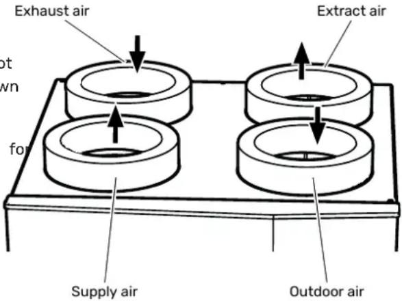

NOTE
To ensure a sealed connection to ERS S40, the supplied hose clips must be used for connecting the air ducts.
RIGHT-HAND VERSION
EXHAUST AIR DUCT /KITCHEN FAN
Exhaust air duct (kitchen fan) must not be connected to ERS S40.
To prevent cooking odours from being led to the ERS S40, the distance between the kitchen fan and the exhaust air valve must be taken into consideration. The distance must not be less than 1.5 m, but may vary between dierent installations.
Always use a kitchen fan when cooking.

Ventilation ow
Connect ERS S40 so that all the exhaust air, except kitchen duct air (kitchen fan), passes through the heat exchanger (EP29) in the product.
Electrical connection

NOTE
All electrical connections must be carried out an authorised electrician.
Electrical installation and wiring must be carried out in accordance with national provisions.
ERS S40 must not be powered during installation
Connecting to main product
by CONNECTING TO THE HEAT PUMP
ERS S40 contains an accessory board (AA33) that connects directly to the main product's input board (terminal block AA2-X30).
on. The communication cable (W119) is connected to the AJB board (AA33) from the factory.
If several accessories are to be connected, or are already installed, the boards are connected in series.

NOTE
If the supply cable is damaged, only NIBE, its service representative or similar authorised person may replace it to prevent any danger and damage.
- To prevent interference, sensor cables to external connections must not be laid close to high voltage cables.
- The minimum area of communication and sensor cables to external connections must be 0.5 mm 2 up to 50 m, for example EKKX, LiYY or equivalent.
For electrical wiring diagram, see page 27.
Overview, AJB board (AA33)

ser Main product
AA2-X30

Supply
ERS S40 is connected to a earthed single-phase wall socket or a permanent installation. For permanent installations, ERS S40 must be preceded by a circuit breaker with at least a 3 mm breaking gap.
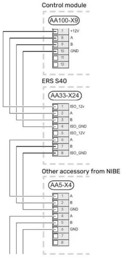
ERS S40 and another accessory from NIBE CONNECTING TO CONTROL MODULE
Because there can be different connections for accessories S40 contains an accessory board (AA33) that connects with accessory board (AA5), you should always read the directly to the main product's input board (terminal block structions in the manual for the accessory that is to be AA100-X9).
stalled.
Main product

The communication cable (W119) is connected to the AJB board (AA33) from the factory.
If several accessories are to be connected, or are already installed, the boards are connected in series.

ERS S40 and another accessory from NIBE DIP SWITCH
Because there can be different connections for accessories the DIP switch (S3) on the AJB board (AA33) must be set with accessory board (AA5), you should always read the as-follows.
structions in the manual for the accessory that is to be in you can have up to 4 ERS S40 in the same installation, each stalled.

ERS S40 no. 1

ERS S40 no. 2

ERS S40 no. 3

ERS S40 no. 4
Commissioning and adjusting
Preparations
- Check that the air Iters are clean, they can become dirtyAvailable pressure after installation. (Pa) 800

Caution
ERS S40 must not be started if the temperature is below -25 °C in the installation area.
Start-up and inspection
SETTING THE VENTILATION
The ventilation must be set according to applicable standards. Adjust the supply air ow to guarantee a negative pressure.
The settings are made in menu 7.1.4.
Even if ventilation is roughly set at installation it is important that a ventilation adjustment is ordered and permitted.

Caution
An incorrectly set ventilation flow can damage the house and may also increase energy consumption.

NOTE
Order a ventilation adjustment to complete the setting.
Ventilation capacity
dirtyAvailable pressure

line
| Airflow (l/s) | Pressure (Pa) | | ------------- | ------------- | | 10 | 100 | | 20 | 150 | | 30 | 200 | | 40 | 250 | | 50 | 300 | | 60 | 350 | | 70 | 400 | | 80 | 450 | | 90 | 500 | | 100 | 550 | | 110 | 600 | | 120 | 650 |Fan rating

line
| Airflow (l/s) | 20% | 30% | 40% | 50% | 60% | 70% | 80% | 90% | 100% | | ------------- | ---- | ---- | ---- | ---- | ---- | ---- | ---- | ---- | ---- | | 10 | 10 | 12 | 15 | 20 | 30 | 40 | 55 | 70 | 85 | | 20 | 12 | 15 | 20 | 25 | 35 | 45 | 55 | 70 | 85 | | 30 | 15 | 18 | 22 | 30 | 40 | 50 | 60 | 75 | 90 | | 40 | 18 | 20 | 25 | 35 | 45 | 55 | 65 | 80 | 95 | | 50 | 20 | 22 | 28 | 40 | 50 | 60 | 70 | 85 | 100 | | 60 | 22 | 25 | 30 | 45 | 55 | 65 | 75 | 90 | 105 | | 70 | 25 | 28 | 32 | 50 | 60 | 70 | 80 | 95 | 110 | | 80 | 28 | 30 | 35 | 55 | 65 | 75 | 85 | 100 | 115 | | 90 | 30 | 32 | 38 | 60 | 70 | 80 | 90 | 105 | 120 | | 100 | 32 | 35 | 40 | 65 | 75 | 85 | 95 | 110 | 125 | | 110 | 35 | 38 | 42 | 70 | 80 | 90 | 100 | 115 | 130 | | 120 | 38 | 40 | 45 | 75 | 85 | 95 | 105 | 120 | 135 | | 130 | 40 | 42 | 48 | 80 | 90 | 100 | 110 | 125 | 140 | | Note: The data is in a format where each line corresponds to a specific percentage value from the input to output. The output values are labeled as 'W' but not explicitly shown in the provided code. There is only one data series in this case. The output values for the top three lines are explicitly labeled as '100%', while the bottom two lines are labeled as '20%'.1 The diagram shows the power consumption per fan.
HUMIDITY
ERS S40 has a built-in humidity sensor (BM20) that is used when demand-controlled ventilation is required.
The speed of the rotor is regulated with respect to a set value depending on the humidity measured in the exhaust air, as well as the calculated humidity outdoors, to achieve the desired relative humidity in the home. The speed of the fans is also regulated, if necessary.
The settings for demand-controlled ventilation are made in menu 7.1.4.4.
Activating ERS S40
Activating ERS S40 can be performed via the start guide Desired supply air temp.: Here, you set the temperature you.
directly in the menu system.
The main product's software must be the latest version.

Caution
Also see the Installer Manual for the main produc
want for the supply air when the re-heater is running When the re-heater is not running, the supply air temperature and the exhaust air temperature will be close to each other.
Time between defrosts, Max. defrosting time, Temp. for of defrosting: Here, you make settings for defrosting.
MENU 1.2.1 - FAN SPEED
Start guide
The start guide appears upon rst start-up after heat pur installation, but is also found in menu 7.7.
Alternatives: normal and speed 1 - speed 4
Menu system
If you do not make all settings via the start guide or need to change any of the settings, this can be done in the menu system. When you have selected a new speed a clock starts a count down. When the time has counted down the ventilation speed returns to the normal setting.
MENU 7.2.1 -ADD/REMOVE ACCESSORIES
Activating/deactivating of accessories.
Select "ERS S40".
The ventilation in the accommodation can be temporarily increased or reduced here.
When you have selected a new speed a clock starts a count down. When the time has counted down the ventilation speed returns to the normal setting.
If necessary, the dierent return times can be changed in menu 1.2.5.
The fan speed is shown in brackets (in percent) after each speed alternative.
MENU 7.2.11 - VENT. HEAT EXCHANGER (ERS) MENU 1.2.2 - NIGHT COOLING
Physical conguration
Setting range: Left, Right
Allow re-heater
Setting range: on/o
Oset re-heater
Setting range: 0.0 - 5.0 °C
Desired supply air temp.
Setting range: 16.5 - 25 °C
Time between defrosts
Setting range: 1 - 8 h
Max. defrosting time
Setting range: 5 - 120 min
Temp. for end of defrosting
Setting range: -10.0 - 10.0 °C
Night cooling
Setting range: on/o
Start temp exhaust air
Setting range: 20 - 30 °C
Min. di. ind. temp. - outd. temp.
Setting range: 3 - 10 °C
Night cooling during heating
Setting range: on/o
Here, you can activate night cooling. When the temperature in the house is high, and the outdoor temperature is lower, a cooling eect can be obtained by forcing the ventilation. When night cooling is activated, the fans run at the speed 4. In this mode, ventilation recovery is stopped.
Start temp exhaust air: Here, you set the exhaust air temperature at which night cooling will start.
Min. di. ind. temp. - outd. temp.: If the temperature difference is greater than the set value for "Min. di. ind. temp. - outd. temp.", and the exhaust air temperature is higher than the set value for "Start temp exhaust air", the ventilation operating at speed 4 until one of these conditions is no longer valid.
Night cooling during heating: It is possible to have night cooling during the time heating is permitted.
Physical conguration: "Left" means that exhaust air and supply air are connected to the left in the product. Chang the conguration requires the conversion of ERS S40.
Allow re-heater: Here, you activate the inbuilt re-heater (EB18).
Oset re-heater: Here, you set the number of degrees the supply temperature must drop below "Desired supply air temp." before the re-heater is permitted to start.
MENU 1.2.5 - FAN RETURN TIME
speed 1 - speed 4
Setting range: 1 - 24 h
Here, you select the return time for the temporary charge of ventilation speed (speed 1 - speed 4), regardless of whether the speed has been changed in menu 1.2.1 - "I speed", via the home screen or via myUplink.
Return time is the time it takes before the temporary speed returns to normal speed.
MENU 1.2.6 - FILTER CLEANING INTERVAL
Months between Iter cleaning
Setting range: 1 - 24 months
The Iters in ERS S40 are of a type that should not be cleaned; they have to be replaced instead. These must be replaced regularly, although how often depends on factors such as the amount of particles in the ventilation air. Test to nd out what is most appropriate for your installation.
Set the interval for the reminder in this menu.
The menu shows the time remaining until the next remindered in order for cooling recovery to start.
and you can also reset active reminders.
MENU 1.2.7 - VENTILATION RECOVERY
Temp stop of heat recovery
Setting range: 5 - 30 °C
Min. di. ind. temp. - outd. temp.
Setting range: 2 - 10 °C
Recovery stop during heating
Setting range: on/o
Cooling recovery
Setting range: on/o
St temp sup air cooled by exh air
Setting range: -20.0 - 41.0 °C
Min di outd and exhaust air
Setting range: 3.0 - 10.0 °C
When there is no heating demand, and the outdoor temperature is approaching the indoor temperature, heat recovery is stopped to prevent the house from being heated furtheA

Caution
Only the heat recovery is stopped, not the ventilation.
Temp stop of heat recovery: Here, you set the outside perature at which ventilation recovery is to stop.
Min. di. ind. temp. - outd. temp.: Here, you set the ature dierence between the indoor air and the outdoor at that is required in order for ventilation recovery to start.
Recovery stop during heating: Stopping ventilation recovery during the time heating is permitted is possible.
Cooling recovery: When there is no heating demand, ventilation recovery is stopped to prevent the house from being heated further. When it is warm indoors and even warmer outdoor, ERS S40 can be used to prevent the house from heating up more than necessary. During cooling recovery, the cooler air from the house is used to cool the incoming air.
"Cooling recovery" is started when the exhaust air temperature is a certain number of degrees below the outdoor temperature and it is warm outside.
St temp sup air cooled by exh air: Here, you set the out temperature at which cooling recovery will start.

Caution
"St temp sup air cooled by exh air" cannot be lower than "Stop heating" in menu 7.1.10.2 - "Auto mode setting".
Min di outd and exhaust air: Here, you set the temperatur dierence between outdoor air and exhaust air that is re-
ndetred in order for cooling recovery to start.
MENU 7.1.4.1 - FAN SPEED, EXHAUST AIR
Fan speed
"Normal" and "Fan speed 1" - "Fan speed 4"
Setting range: 0 - 100%
Set the speed for the ve dierent selectable speeds for the fan here.
MENU 7.1.4.2 - FAN SPEED, SUPPLY AIR
Fan speed
"Normal" and "Fan speed 1" - "Fan speed 4"
Setting range: 0 - 100%
Set the speed for the ve dierent selectable speeds for the fan here.
MENU 7.1.4.4 - DEMAND CONTR. VENTILATION
Humidity controlled ventilation
eAlternative: on/o
Highest fan speed
Setting range: 1 - 100%
-Lowest fan speed
Setting range: 1 - 100%
Time interv. change of fan speed
Setting range: 1 - 60 minutes
Controlling zones
temper- Activate zones for demand-controlled ventilation.
Here, you make settings for demand-controlled ventilation.
The speed of the fan can be changed depending on the humidity in the air.
MENU 6.2 - SCHEDULING
In this menu, you schedule repeated changes of ventilation.

Caution
A schedule repeats according to the selected setting (e.g. every Monday) until you go into the menu and switch it o.
MENU 7.4 - SELECTABLE IN/OUTPUTS
Select here whether you want to activate fan speed for the relevant AUX input.
Disturbances in comfort
In most cases, the main product notes a malfunction (a • External switch for changing the fan speed activated.
malfunction can lead to disturbance in comfort) and indic- - Check any external switches.
ates this with alarms and shows action instructions in the
display.
- Silencers not correctly installed.
- Check the silencers.
Troubleshooting
If the operational interference is not shown in the display the following tips can be used:
BASIC ACTIONS
Start by checking the following items:
- That the main product is running and that the supply cable to ERS S40 is connected.
- Group and main fuses of the accommodation.
• The property's earth circuit breaker.
• Temperature limiter for ERS S40 (FQ10).
HIGH OR LOW ROOM TEMPERATURE
- The re-heater (EB18) is not activated.
- Activate the re-heater in menu 7.2.11.
LOW OR A LACK OF VENTILATION
- The exhaust air Iter (HQ10) and/or the supply air Iter (HQ11) is clogged.
- Replace the Iters.
• The ventilation is not adjusted. - Order/implement ventilation adjustment.
- Closed, too much choke or blocked ventilation device.
- Check and clean the ventilation devices.
• Fan speed in reduced mode. - Enter the main product's menu 1.2.1 and select "Normal".
- External switch for changing the fan speed activated.
- Check any external switches.
HIGH OR DISTRACTING VENTILATION
- The exhaust air Iter (HQ10) and/or the supply air Iter (HQ11) is clogged.
- Replace the Iters.
• The ventilation is not adjusted. - Order/implement ventilation adjustment.
- Closed, too much choke or blocked ventilation device.
- Check and clean the exhaust air devices.
- Fan speed in forced mode.
- Enter the main product's menu 1.2.1 and select "Normal".
Accessories
Detailed information about the accessories and complete accessories list available at nibe.eu.
TOP CABINET TOC 40
Top cabinet that conceals the ventilation ducts and reduces the sound to the installation room.
Height 245 mm
Part no. 089 756
Height 345 mm
Part no. 089 757
Height 445 mm
Part no. 067 522
Height 385 - 635 mm
Part no. 089 758
Technical data
Dimensions
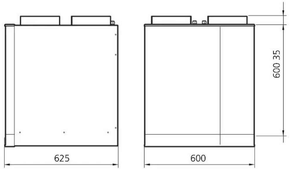
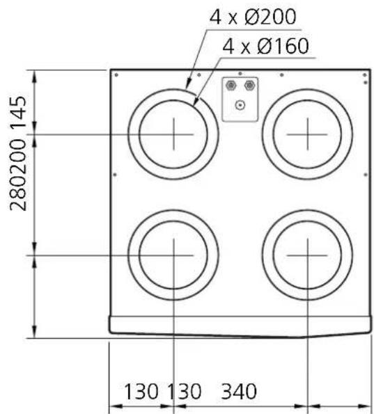
Technical specifications
| ERS S40Type | ||
| Electrical data | ||
| 230 V - 50HzVSupply | ||
| 10AFuse | ||
| 1000WPower, re-he | ||
| 2 x 90WDriving pov | ||
| IP X1BEnclosure cla | ||
| Ventilation | ||
| Coarse 65%Filter type | ||
| ePM1 55%Filter type. | ||
| Noise | ||
| w(A)1 | 51dB(A)Sound pov | |
| P(A) at 1 m | 40dB(A)Sound pr | |
| Pipe connections | ||
| Ventilation θ | 160mm | |
| Dimensions and weight | ||
| Eciency class 3 | A | |
| Length, supply cable | m | 2.4 |
| Length, communication cable | m | 2.4 |
| Width | 600mm | |
| Height | 600mm | |
| Depth | 620mm | |
| Weight | kg | 45 |
| Part No. | 066 242 | |
1 89 l/s (320 h) at 50 Pa
2 72 l/s (260 m/h) at 50 Pa
3 Scale for eciency class: A+ to G.
Temperature and humidity efficiency according to EN 13141-7
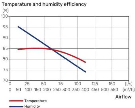
line
| Airflow (m³/h) | Temperature (%) | Humidity (%) | | -------------- | --------------- | ------------ | | 0 | 84 | 95 | | 50 | 84.5 | 93 | | 100 | 84.5 | 90 | | 150 | 84.5 | 87 | | 200 | 84.5 | 84 | | 250 | 84 | 81 | | 300 | 83 | 78 | | 350 | 81 | 76 | | 400 | 78 | 74 |RPM: 25 Outdoor air: 7 °C RH 80% Exhaust air: 20 °C RH 38%
Energy labelling
| NIBESupplier | ||
| ERS S40-400Model | ||
| Specific energy consumption (SEC) | kWh/(m2year) | Average: -37.9Cold: -74.8Warm: -14.2 |
| Energy eciency class | A | |
| RVU, BidirectionalDeclared typology | ||
| Variable speed driveType of drive | ||
| RegenerativeType of heat recovery system | ||
| 82Thermal eciency of heat recovery | ||
| m3/hMax | mum air ow rate 460 | |
| ow rate | 178WElectric power input of the fan drive a | |
| 51dBSound power level (LWA) | ||
| Reference ow rate | 3/s | 0.089m |
| 50PaReference pressure dience | ||
| Specific power input (SPI) | W/m3/h | 0.25 |
| Control factor and control typology | Local demand control (0.85) | |
| %External leakage rates | Internal: 3.2External: 0.6 | |
| Information about Iter warning | See user manual. | |
| Information about supply/exhaust grilles in the facade | See section General ventilation connections on page 14. | |
| Information about pre-/disassembly | See section Recovery on page 5.This installer manual can also be accessed at nibe.eu. | |
| The annual electricity consumption | kWh/year | 275 |
| Annual heating saved, kWh primary energy per year | kWhprim/year | Average: 4,413Cold: 8,633Warm: 1,996 |
Electrical circuit diagram

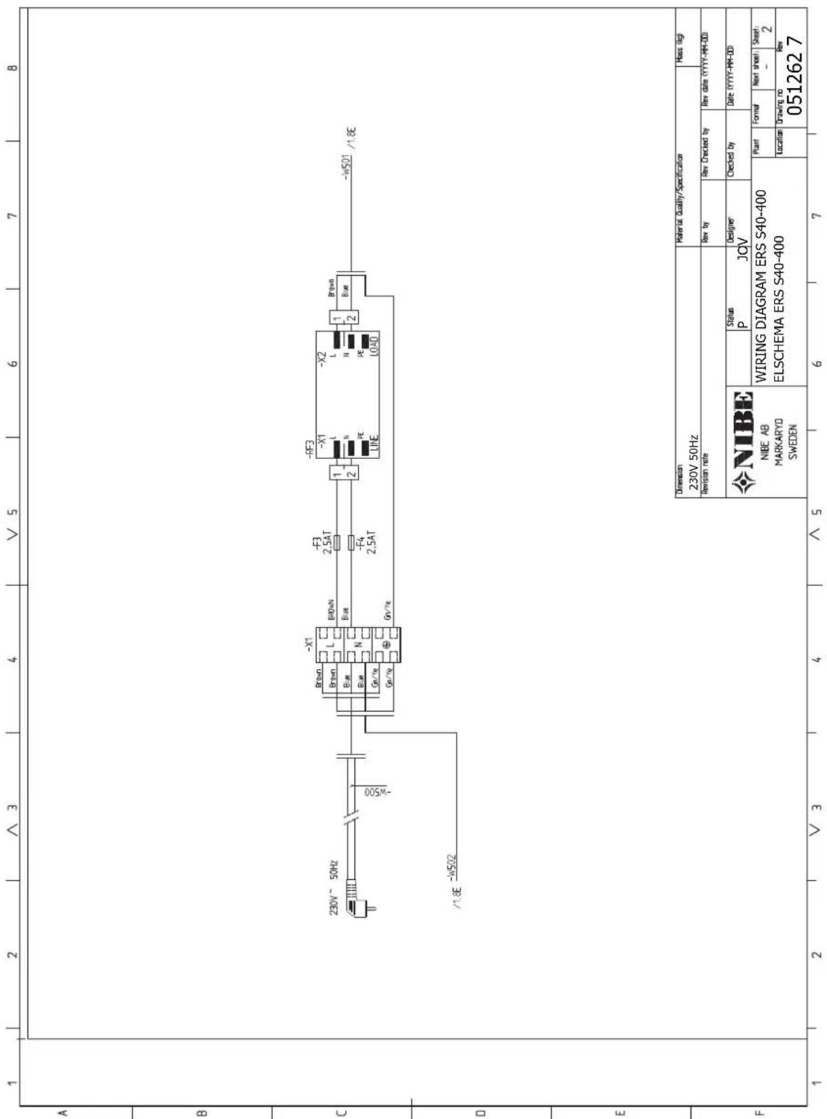
Item register
A
Accessories, 23
Adjusting ventilation, 14
Assembly, 11
C
Commissioning and adjusting, 18 Preparations, 18
D
Delivery and handling, 7
Assembly, 11
Installation, 11
Installation area, 11
Physical conguration
Left-handed version, 8
Right-handed version, 8
Removing the covers, 7
Supplied components, 7
Transport and storage, 7
Design of the HRV unit, 12
Dimensions and ventilation connections, 14
Disturbances in comfort, 22
Troubleshooting, 22
E
Electrical connection, 15
Connecting to main product, 15
DIP switch, 17
Energy labelling, 26
Exhaust air duct, 14
G
General ventilation connections, 14
I
Important information, 4
Recycling, 5
Inspection of the installation, 6
Installation area, 11
L
Left-handed version, 8
M
Menu system, 19
Mounting, 11
P
Physical conguration
Left-handed version, 8
Right-handed version, 8
Pipe and ventilation connections
Exhaust air duct, 14
Program settings, 19
R
Recycling, 5
Removing the covers, 7
Right-hand version, 8
s
Safety information
Inspection of the installation, 6
Serial number, 4
Start guide, 19
Start-up and inspection
Setting the ventilation, 18
Supplied components, 7
T
The design of the exhaust air module
List of components, 13
Transport and storage, 7
Troubleshooting, 22
V
Ventilation connections, 14
Adjusting ventilation, 14
Dimensions and ventilation connections, 14
General ventilation connections, 14
Ventilation ows, 14
Ventilation ow, 14
Contact information
DENMARKCZECH REPUBLICAUSTRIA
NIBE Energy Systems France SAS
Zone industrielle RD 28
NIBE Energy Systems Ltd
3C Broom Business Park,
Bridge Way, S41 9QG Chestereld
Tel: +44 (0)330 311 2201
info@nibe.co.uk
nibe.co.uk
NIBE-BIAWAR Sp. z o.o.
Al. Jana Pawla II 57, 15-703 BialystoBox 14
Tel: +48 (0)85 66 28 490 Hannabadsvägen 5, 285 21 MarkarydTel. +41 (0)58 252 21 00
biawar.com.pl Tel: +46 (0)
Tel: +46 (0)433-27 30 00 info@nibe.ch
info@nibe.se nibe.ch
nibe.se
For countries not mentioned in this list, contact NIBE Sweden or check nibe.eu for more information.
NIBE Energy Systems
Hannabadsvägen 5
Box 14
SE-285 21 Markaryd
info@nibe.se
nibe.eu
This is a publication from NIBE Energy Systems. All product illustrations, facts and data are on the available information at the time of the publication's approval.
NIBE Energy Systems makes reservations for any factual or printing errors in this publication
- Table of Contents
- Important information
- Safety information
- Serial number
- Symbols
- Recovery
- Inspection of the installation
- Delivery and handling
- Transport and storage
- Supplied components
- Compatible products
- INNER FRONT COVER
- Removing the covers
- FRONT COVER
- Physical conguration
- CONVERSION TO RIGHT-HANDED VERSION
- Caution
- Assembly
- Mounting
- INSTALLATION AREA
- NOTE
- Design of the HRV unit
- Pipe connections
- Sensors etc.
- Electrical components
- Ventilation
- Miscellaneous
- Ventilation connections
- General ventilation connections
- Adjusting ventilation
- FT-HANDED VERSION
- RIGHT-HAND VERSION
- EXHAUST AIR DUCT /KITCHEN FAN
- Ventilation ow
- Electrical connection
- Connecting to main product
- by CONNECTING TO THE HEAT PUMP
- Overview, AJB board (AA33)
- Supply
- ERS S40 and another accessory from NIBE CONNECTING TO CONTROL MODULE
- ERS S40 and another accessory from NIBE DIP SWITCH
- Commissioning and adjusting
- Preparations
- Start-up and inspection
- SETTING THE VENTILATION
- HUMIDITY
- Activating ERS S40
- MENU 1.2.1 - FAN SPEED
- Start guide
- Menu system
- MENU 7.2.1 -ADD/REMOVE ACCESSORIES
- MENU 7.2.11 - VENT. HEAT EXCHANGER (ERS) MENU 1.2.2 - NIGHT COOLING
- Allow re-heater
- Oset re-heater
- Desired supply air temp.
- Time between defrosts
- Max. defrosting time
- Temp. for end of defrosting
- Night cooling
- Start temp exhaust air
- Min. di. ind. temp. - outd. temp.
- Night cooling during heating
- MENU 1.2.5 - FAN RETURN TIME
- MENU 1.2.6 - FILTER CLEANING INTERVAL
- Months between Iter cleaning
- MENU 1.2.7 - VENTILATION RECOVERY
- MENU 7.1.4.1 - FAN SPEED, EXHAUST AIR
- MENU 7.1.4.2 - FAN SPEED, SUPPLY AIR
- MENU 7.1.4.4 - DEMAND CONTR. VENTILATION
- MENU 6.2 - SCHEDULING
- MENU 7.4 - SELECTABLE IN/OUTPUTS
- Disturbances in comfort
- Troubleshooting
- BASIC ACTIONS
- HIGH OR LOW ROOM TEMPERATURE
- LOW OR A LACK OF VENTILATION
- HIGH OR DISTRACTING VENTILATION
- Accessories
- TOP CABINET TOC 40
- Technical data
- Temperature and humidity efficiency according to EN 13141-7
- Electrical circuit diagram
- Item register
- A
- C
- D
- E
- G
- I
- L
- M
- P
- R
- s
- T
- V
- Contact information
- DENMARKCZECH REPUBLICAUSTRIA
Brand : Nibe
Model : ERS S40-400
Category : Heat pump