
SonoCollect 112 - Meter DANFOSS - Free user manual and instructions
Find the device manual for free SonoCollect 112 DANFOSS in PDF.


| Product Type | Ultrasonic energy meter |
| Model | SonoCollect 112 |
| Brand | Danfoss |
| Application | Heating and cooling energy measurement |
| Measurement Principle | Ultrasonic transit-time |
| Measured Values | Flow rate, supply/return temperature, thermal energy |
| Nominal Diameter | DN 15 to DN 50 (typical) |
| Flow Range | 0.05 to 15 m³/h (depends on DN) |
| Accuracy Class | EN 1434 Class 2 |
| Temperature Range | 5 °C to 90 °C (heat), 0 °C to 50 °C (cooling) |
| Power Supply | Battery (lithium, life > 10 years) or external 24 V AC/DC |
| Communication | M-Bus, pulse output, or wireless (optional) |
| Display | LCD with 8-digit alphanumeric |
| Protection Class | IP54 (electronics), IP68 (sensor) |
| Dimensions (Electronics Unit) | 120 x 80 x 45 mm |
| Weight | Approx. 0.5 kg |
| Ambient Temperature | 5 °C to 55 °C |
| Installation | Horizontal or vertical, flow sensor in pipe |
| Maintenance | Periodic cleaning of filter and sensor; battery replacement |
| Safety Standards | EN 1434, MID (Measuring Instruments Directive) |
| Spare Parts | Battery, display module, flow sensor |
Frequently Asked Questions - SonoCollect 112 DANFOSS
User questions about SonoCollect 112 DANFOSS
0 question about this device. Answer the ones you know or ask your own.
Ask a new question about this device
Download the instructions for your Meter in PDF format for free! Find your manual SonoCollect 112 - DANFOSS and take your electronic device back in hand. On this page are published all the documents necessary for the use of your device. SonoCollect 112 by DANFOSS.
USER MANUAL SonoCollect 112 DANFOSS
natural_image
Exterior view of a Siemens SintColecta 11.2 PLC device with visible control buttons and green/red connectors (no text or symbols on main body)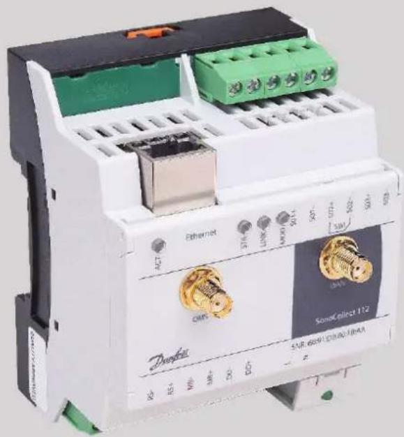
Table of Contents
1 Notes and conventions....6
1.1 About this document....6
1.2 Legal basis 6
1.2.1 Copyright protection 6
1.2.2 Personnel qualification....6
1.2.3 Intended use....6
1.3 Symbols 6
1.4 Font conventions....6
1.5 Number notation....7
1.6 Safety guidelines ....7
1.7 Scope....7
1.8 Abbreviations ....7
2 Presentation of the device....9
2.1 Delivery variants....9
2.2 Connectors....9
2.3 Status LEDs 10
2.4 First steps 10
2.4.1 Power supply 10
2.4.2 Network configuration and first access 11
2.5 Specific troubleshooting SonoCollect 112....12
2.5.1 All LEDs remain dark, the device does not respond.... 12
2.5.2 The Power LED flashes green....12
2.6 Typical application scenarios 12
2.6.1 Local application without control system 13
2.6.2 Remote monitoring without control system 13
2.6.3 Remote monitoring with email dispatch 13
2.6.4 Remote monitoring with FTP upload....13
2.6.5 Remote monitoring with SFTP upload....13
2.6.6 Remote monitoring with TCP/HTTP transmission 14
2.7 Technical data 14
2.7.1 General properties 14
2.7.2 Electrical properties....14
2.7.3 Further characteristics....15
3 Netdiscover tool....16
3.1 Locating and accessing devices 16
3.2 Network configuration....17
3.3 Access to the web-based front end via HTTP 18
3.4 Access to the file system via FTP 18
3.5 Access to the command line via SSH....20
3.6 Mass management 20
3.7 Import of a device list....22
4 Web-based front end....23
4.1 Access via HTTPS 23
4.2 General tab 24
4.3 Meter tab....25
4.3.1 System meter....27
4.4 Configuration tab....28
4.5 WAN tab 30
4.6 Server tab 32
4.7 Security tab....34
4.8 User tab....34
4.9 Log tab 36
4.10 Service tab 37
4.11 Print page....39
4.12 Supplied manual 41
4.13 Front-end troubleshooting....41
4.13.1 Website or front end cannot be accessed 41
4.13.2 Login on website not possible....41
4.13.3 All input fields or buttons are greyed out.... 41
4.13.4 Not all tabs are visible 41
4.13.5 Export of the log data of one/several meters is empty 42
4.13.6 The log is empty 42
5 Reading meters via M-Bus....43
5.1 Signalling on the M-Bus 43
5.2 Setup of the interface in the web front end....44
5.2.1 M-Bus mode 44
5.2.2 Addressing, search and search range....45
5.2.3 M-Bus baud rate 47
5.2.4 M-Bus timeouts....47
5.2.5 M-Bus request mode 47
5.2.6 M-Bus reset mode 47
5.2.7 M-Bus multipaging 48
5.3 M-Bus troubleshooting 48
5.3.1 Physical troubleshooting....48
5.3.2 M-Bus meters are not found 49
5.3.3 M-Bus meters are found, but do not show any data 49
5.3.4 The search takes a long time 50
5.3.5 Device restarts during search....50
6 Reading meters via wM bus....51
6.1 Signalling via wM bus 51
6.2 Troubleshooting the wM bus....51
6.2.1 wM-Bus meters are not found 51
6.2.2 wM-Bus mounters are found but show no data 52
7 Reading meters via pulse interface....53
7.1 Setup of a meter in the web front end....53
7.2 Troubleshooting the pulse interface 55
7.2.1 The meter does not increment 55
8 Reading meters via serial interface 56
8.1 Setup of the interface in the web front end....56
8.1.1 Serial mode....56
8.1.2 DLDE baud rate, data bits, stop bits and parity....56
8.1.3 DLDE mode....57
8.1.4 DLDE timeouts 57
8.2 Setup of the meter in the web front end 57
8.3 Troubleshooting the serial interface....59
8.3.1 Meters are not read out....59
9 Transmission of meter data 60
9.1 Instances and database....60
9.2 General settings....60
9.3 Preset data or file formats 60
9.3.1 XML format....60
9.3.2 CSV format....62
9.3.3 JSON format 63
9.3.4 User format....64
9.4 Data transmission via TCP 65
9.5 Data transmission via TLS....65
9.6 Sending files via FTP 67
9.6.1 Sending files via SFTP or FTPS....67
9.7 Sending e-mails via SMTP....68
9.7.1 Report as content of the e-mail 68
9.7.2 Report as attachment to an e-mail 68
9.7.3 SMTP with STARTLS 68
9.8 Data transmission via MQTT....69
9.8.1 Example Azure Cloud....69
9.8.2 Example AWS Cloud 70
9.9 Local file storage....71
9.10 Script-based report....72
9.11 Specific troubleshooting 72
10 Advanced configuration options 73
10.1 Linux operating system....73
10.1.1 User rights....73
10.1.2 Command line 73
10.1.3 Standard commands....73
10.2 Update 74
10.3 Configuration file chip.ini 75
10.4 Configuration file Device_Handle.cfg....84
10.5 OpenVPN Client 85
10.5.1 Configuration of the device 85
10.6 Preconfiguration of the meter list 85
10.7 Scripting 86
10.7.1 XSLT parser....86
10.7.2 Report script....86
10.7.3 System meter script....87
10.8 Media types, measurement types and units 88
11 Access to meter data via Modbus TCP 92
11.1 General information....92
11.2 Function codes and addressing 92
11.3 Data display....93
11.4 Configuration via web front end....95
11.4.1 Modbus mode and Modbus port 95
11.4.2 Modbus test 95
11.4.3 Modbus swap 96
11.4.4 Modbus float only 96
11.4.5 Modbus multi slave 97
11.5 Instructions for use 97
11.5.1 How often is the data updated? 97
11.5.2 How can you detect if the meter is read or the value is current? 97
11.5.3 Which data type must be used? 98
11.5.4 What is the unit of value? 98
11.5.5 How many Modbus masters can call data simultaneously? 98
11.5.6 How can the data be automatically assigned? 98
11.6 Specific troubleshooting 99
11.6.1 Why does the value in the Modbus differ from the value on the website?......99
11.6.2 Why does the device/the Modbus server not respond? 99
12 Access to meter data via BACnet IP....100
12.1 General information....100
12.1.1 Implemented services .... 100
12.1.2 Supported BACnet Interoperability Building Blocks (Annex K)....100
12.2 Configuration via web front end....100
12.2.1 BACnet active 100
12.2.2 BACnet config network, BACnet IP, BACnet netmask und BACnet broadcast .... 100
12.2.3 BACnet BBMD 100
12.2.4 BACnet port....101
12.2.5 BACnet device ID, BACnet device name and BACnet location 101
12.2.6 Change of Value....101
12.2.7 Export of an EDE file 101
12.3 Data display....101
12.3.1 Meter values....101
12.3.2 BACnet Device object....102
12.4 Specific troubleshooting 103
1 Notes and conventions
1.1 About this document
This manual provides guidance and procedures for a fast and efficient installation and start-up of the units described in this manual. It is imperative to read and carefully follow the safety guidelines.
1.2 Legal basis
1.2.1 Copyright protection
This documentation, including all illustrations contained therein, is protected by copyright. The author is Danfoss A/S, Nordborg. The exploitation rights are also held by Danfoss A/S. Any further use that deviates from the copyright regulations is not allowed. Reproduction, translation into other languages, as well as electronic and phototechnical archiving and modification require the written permission of Danfoss A/S.
Violations will result in a claim for damages.
Danfoss A/Sreserves the right to provide for any alterations or modifications that serve to increase the efficiency of technical progress. All rights in the event of the granting of a patent or the protection of a utility model are reserved by Danfoss A/S. Third-party products are always mentioned without reference to patent rights. The existence of such rights can therefore not be excluded.
1.2.2 Personnel qualification
The product use described in this documentation is intended exclusively for electronics specialists or persons instructed by electronics specialists. They must all have good knowledge in the following areas:
■ Applicable standards
■ Use of electronic devices
The solidus GmbH accepts no liability for faulty actions and damage to the described devices and third-party products caused by disregarding the information in this manual.
1.2.3 Intended use
If necessary, the components or assemblies are delivered ex works with a fixed hardware and software configuration for the respective application. Modifications are only permitted within the scope of the possibilities shown in the documentation. All other changes to the hardware or software as well as the non-intended use of the components result in the exclusion of liability on the part of Danfoss A/S.
Please send any requests for a modified or new hardware or software configuration to Danfoss A/S.
1.3 Symbols
Caution: It is essential to observe this information in order to prevent damage to the device.
Notice: Boundary conditions that must always be observed to ensure smooth and efficient operation.
ESD (Electrostatic Discharge): Warning of danger to components due to electrostatic discharge. Observe precautionary measures when handling components at risk of electrostatic discharge.
√ Note: Routines or advice for efficient equipment use.
Further information: References to additional literature, manuals, data sheets and internet pages.
1.4 Font conventions
Names of paths and files are marked in italics. According to the system the notation is done by slash or backslash.
e. g.: D:\Data
Menu items or tabs are marked in bold italics.
e. g.: Save
An arrow between two menu items or tabs indicates the selection of a sub-menu item from a menu or a navigation history in the web browser.
■ e.g.: File→New
Buttons and input fields are shown in bold letters.
e.g.: Input
Key labels are enclosed in angle brackets and shown in bold with capital letters.
e.g.:
Program codes are printed in Courier font.
e.g.: ENDVAR
Variable names, identifiers and parameter entries are marked in italics in the text.
e. g.: Measured value
1.5 Number notation
Numbers a noted according to this table:
| Number system | Example | Comments |
| Decimal | 100 | Normal notation |
| Hexadecimal | 0x64 | C notation |
| Binary | '100' '0110.0100' | in quotation marks nibbles separated by dot |
Table 1: Number systems
1.6 Safety guidelines
The power supply must be switched off before replacing components and modules.
If the contacts are deformed, the affected module or connector must be replaced, as the function is not guaranteed in the long term. The components are not resistant to substances that have creeping and insulating properties. These include e.g. aerosols, silicones, triglycerides (ingredient of some hand creams). If the presence of these substances in the vicinity of the components cannot be excluded, additional measures must be taken. Install the components in an appropriate casing. Handle components with clean tools and materials only.
Only use a soft, wet cloth for cleaning. Soapy water is allowed. Pay attention to ESD.
Do not use solvents like alcohol, acetone etc. for cleaning.
Do not use a contact spray, because in an extreme case the function of the contact point is impaired and may lead to short circuits.
Assemblies, especially OEM modules, are designed for installation in electronic housings. Do not touch the assembly when it is live. In each case, the valid standards and directives applicable to the construction of control cabinets must be observed.
The components are populated with electronic elements which can be destroyed by an electrostatic discharge. When handling the components, ensure that everything in the vicinity is well earthed (personnel, workplace and packaging). Do not touch electrically conductive components, e.g. data contacts.
1.7 Scope
This documentation describes the devices made by Danfoss A/S, Nordborg stated in the title.
1.8 Abbreviations
| Abbreviation | Meaning |
| 2G | Mobile radio standard, synonym for GSM or GPRS |
| 3G | Mobile radio standard, synonym for UMTS |
| 4G | Mobile radio standard, synonym for LTE |
| BACnet | Building Automation and Control networks |
| BBMD | BACnet Broadcast Management Device |
| CA | Certification Authority |
| CHAP | Challenge Handshake Authentication Protocol |
| COSEM | C Omanian Specification for Energy Metering |
| CSV | Character-Separated Values |
| DNS | Domain Name System |
| DE, DI | Digital Input, Digital Input Terminal |
| DA, DO | Digital Output, Digital Output Terminal |
| DIN | German Institute for Standardization |
| DLDE | Direct Local Data Exchange (EN 62056-21, IEC 1107) |
| DLDERS | DLDE communication via RS-232 or RS-485 |
| DLMS | Device Language Message Specification |
| I/O | Input / output |
| ESD | ElectroStatic Discharge |
| FNN | Forum Network Technology/Network Operation |
| FTP | File Transfer Protocol |
| GPRS | General Packet Radio Service |
| GSM | Global System for Mobile Communications |
| HTTP | Hypertext Transfer Protocol |
| I/O | Input/Output |
| ICMP | Internet Control Message Protocol |
| ID | Identification, identifier, unique marking |
| IoT | Internet of Things |
| IP | Internet Protocol or IP address |
| JSON | JavaScript Object Notation |
| LED | Light-Emitting Diode |
| LSB | Least significant byte |
| LSW | Least significant word |
| LTE | Long Term Evolution |
| M-Bus | Meter bus (EN 13757, part 2 - 3) |
| MAC | Medium Access Control or MAC address |
| MEI | Modbus Encapsulated Interface |
| MQTT | Message Queuing Telemetry Transport |
| MSB | Most Significant Byte |
| MSW | Most Significant Word |
| MUC | Multi Utility Communication, MUC-Controller |
| NBIoT | Narrow Band Internet of Things |
| OEM | Original Equipment Manufacturer |
| OMS | Open Metering System |
| PAP | Password Authentication Protocol |
| PEM | Privacy Enhanced Mail |
| PPP | Point-to-Point Protocol |
| PPPoE | Point-to-Point Protocol over Ethernet |
| RFC | Requests For Comments |
| RSSI | Received Signal Strength Indicator |
| RTC | Real Time Clock |
| RTOS | Real-Time Operating System |
| SO | SO interface (pulse interface, EN 62053-31) |
| SIM | Subscriber Identity Module |
| SML | Smart Message Language |
| SMTP | Simple Mail Transfer Protocol |
| SNTP | Simple Network Time Protocol |
| SSL | Secure Socket Layer |
| TCP | Transmission Control Protocol |
| TLS Transport Layer Security | |
| UDP | User Datagram Protocol |
| UMTS | Universal Mobile Telecommunications System |
| UTC | Universal Time Coordinated |
| VDE | Association of Electrical, Electronic & Information Technologies e.V. |
| WAN | Wide Area Network |
| wM-Bus | Wireless Meter Bus (EN 13757, part 3 - 4) |
| XML | eXtensible Markup Language |
| XSLT | eXtensible Stylesheet Language Transformation |
Table 2: Abbreviations
2 Presentation of the device
SonoCollect stands for a communication module, which automatically records customer's consumption data within the scope of Smart Metering. This is sent via a wide area network (WAN) to the measuring service provider or measuring point provider and, via a local interface, it can also be displayed on a customer PC.
The so-called SonoCollect 112 is a variant of such a communication module. This is separate from the meter, and acts as the data transport interface. The SonoCollect is the central device for the implementation of Smart Metering. Its advantage is that the measuring equipment and short-lived wide area communication are installed in separate devices, and so can be installed or exchanged independently of each other.
The SonoCollect 112 is a modular controller. The device comes in a 4U enclosure (modules) and is intended for DIN rail mounting (DIN rail 35 mm).
2.1 Delivery variants
The SonoCollect 112 is offered in a range of versions, and so can easily be adapted to the requirements of the particular property.
| Variant | Order number | Meter interfaces | Communication interfaces | Outputs | ||||
| M-Bus | wM-Bus | S0 | Ethernet | WAN | RS-485 | Digital 24 V | ||
| SonoCollect 112 E-WM-80 | 014U1603 | X | X | 3 | X | - | X | 1 |
| SonoCollect 112 G-WM-80 | 014U1605 | X | X | 3 | X | X (LTE) | X | 1 |
| SonoCollect 112 EB-WM-80* | 014U1609 | X | X | 3 | X | - | X | 1 |
| SonoCollect 112 GB-WM-80* | 014U1612 | X | X | 3 | X | X (LTE) | X | 1 |
Table 3: Abbreviations
*The Variants "EB-WM-80" and "GB-WM-80" includes the BACnet IP communication protocol.
The RS485 interface can be used both for communication (e.g. with a display (optional) and for reading meters.
2.2 Connectors
The various interfaces of the SonoCollect 112 are on different sides of the device.
The following figure shows the device variants:
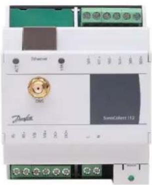
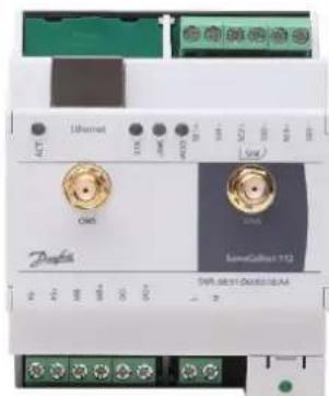
The following connectors are available at SonoCollect 112:
| Connector | Designation | Pinning | Comments |
| Power supply | N, L | N: neutral conductorL: Phase conductor | 230 VAC (90-260 VAC), 50 HzScrew clampConnection cable 2.5 mm^2 |
| Ethernet connection | Ethernet | 1: TX+2: TX-3: RX+4:5:6: RX-7:8: | according to EIA/TIA 568A/B |
| RS-485 | RS+, RS- | RS+: positive bus lineRS-: negative bus line | Screw clampConnection cable 2.5 mm ^2 |
| WAN antenna | WAN | Inner: RFOuter: Reference ground | SMAwith 4G variant only |
| wireless M-Bus antenna | OMS | Inner: RFOuter: Reference ground | SMA |
| M-Bus connection | MB+, MB- | MB+: positive bus lineMB-: negative bus line | Screw clampConnection cable 2.5 mm ^2 |
| S0 inputs | Sx+, Sx(x = 1..3) | Sx+: Pulse inputSx-: Reference ground | Screw clampConnection cable 2.5 mm ^2 Voltage range 24 VDCNo galvanic isolation |
| Digital output | DO+, DO- | DO+: OutputDO-: Reference ground | Screw clampConnection cable 2.5 mm ^2 24 VDC, 100 mANo galvanic isolation |
Table 4: Pin assignments
2.3 Status LEDs
Depending on the version, the SonoCollect 112 has up to 5 status LEDs. These indicate the following states:
| LED | Colour | Meaning |
| Power | green | Power supply active |
| Active (ACT) | Off | inactive, waiting state |
| green | Meter reading | |
| State (STA) | Off | Software is not started |
| green | Main program is running | |
| orange (flashing) | Scanning meters | |
| orange | Initialization is running | |
| red | Error | |
| Mode* | off | No connection |
| red (flashing) | Data connection setup | |
| red | Low received field strength | |
| yellow | Average received field strength | |
| green | Good received field strength | |
| Link* | Off | WAN module switched off |
| green | WAN module switched on (no data connection) | |
| yellow | WAN module switched on + data connection (no data traffic) | |
| white | WAN module switched on + data connection (active data traffic) |
*only available in variant with WAN
Table 5: Status LEDs (all models)
In the operating state, the State LED is green and the active LED flashes green briefly during the readout. The Mode LED indicates the reception field strength when the WAN connection is active at and the Link LED lights up yellow or white when the WAN connection is active.
2.4 First steps
2.4.1 Power supply
The SonoCollect 112 has an integrated power supply unit and is supplied with 230 VAC (wide input voltage range). Therefore, initially only the supply of the device must be ensured. The SonoCollect 112 starts automatically after connection to the supply voltage.
By default, following calls are made on system startup:
- Configuration of the network interface (Ethernet) via DHCP or static configuration
■ Initial generation of SSL device keys (needs some time at first startup) - Obtaining the system time via SNTP
■ Starting the system services
■ Start of the main program
The main program then provides the entire functionality, including the web interface of the SonoCollect 112.
2.4.2 Network configuration and first access
The SonoCollect 112 can be completely configured via the network interface. This must therefore be configured according to your network. If necessary, ask your administrator.
SonoCollect 112 is set by default to the static IP address 192.168.1.101 (subnet mask: 255.255.255.0, gateway: 192.168.1.254).
For intuitive operation, a configuration website is available on the device, which can be accessed via
→ website on the SonoCollect 112, e.g.: http://192.168.1.101
when handling multiple devices under one IP (e.g. commissioning) or different software versions (e.g. update), you should always empty the cache of the browser (e.g. Ctrl+F5) to prevent an inconsistent display of the website.
The following site opens in the browser:
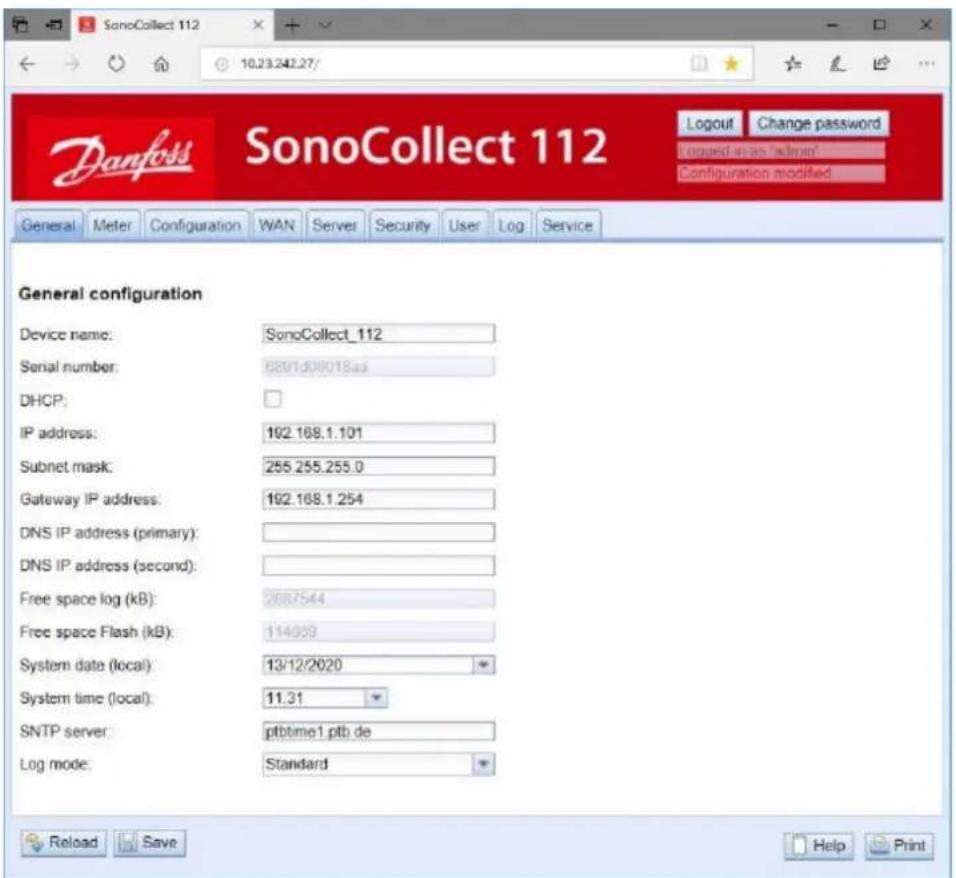
Figure 2 Website of the SonoCollect 112
The web frontend is described separately in chapter 4. There you will find a detailed overview of the functionalities of the web-based frontend.
In addition, access via SFTP, SCP, FTPS (file transfer) or via SSH (console) is also possible by default:
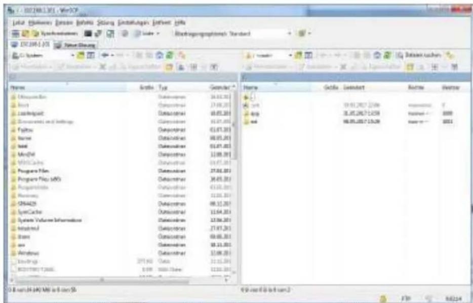
Figure 3 WinSCP main window after connection establishment
2.5 Specific troubleshooting SonoCollect 112
2.5.1 All LEDs remain dark, the device does not respond.
CAUTION LIFE HAZARD: The testing of the power supply may only be carried out by trained personnel.
Switch off the power supply. Remove all cables and antennas except the power supply. Now switch on the power supply and check the voltage level from 90 to 260 VAC.
Ensure that no faults are caused by the infrastructure, circuit breakers or circuit breakers of the power supply. Test the SonoCollect 112 under laboratory conditions if necessary.
If errors could not be rectified, please contact your local Danfoss customer support.
2.5.2 The Power LED flashes green.
Switch off the power supply. Remove all cables and antennas except the power supply. Now switch on the power supply and check whether the power LED is now permanently lit.
Now reconnect all cables and antennas one by one and check after each step whether the power LED remains permanently lit.
If the fault actually occurs on the connection of a specific cable, check it more thoroughly. There may be a fault in the external circuitry, e.g. short-circuit or overload. If necessary, replace faulty cables.
If errors could not be rectified, please contact your local Danfoss customer support.
2.6 Typical application scenarios
The following are examples of how the SonoCollect 112 can be used.
To use the SonoCollect 112, the network and meter interfaces must be parameterized according to your application and your plant (see chapter 4).
2.6.1 Local application without control system
The SonoCollect 112 can be used for local meter reading.
No control system is required to collect and store meter data. Server services can therefore be deactivated (Server tab). Only the local storage of CSV files has to be set up.
The SonoCollect 112 is accessed in this application via a PC that is located in the same network. The current meter values can thus be monitored via the website in the Meters tab. The CSV files can be accessed via FTP access, provided logging is active. To do this, connect to the SonoCollect 112 with an FTP client (see chapter: 6.2.2).
Users can be configured in the user management with the corresponding access rights to allow read access to the meter list (see chapter 4.7).
2.6.2 Remote monitoring without control system
This application case is largely equivalent to the example in section 2.6.1. The only difference is the network infrastructure that is set up between a PC and the SonoCollect 112 (Internet). The PC and the SonoCollect 112 are not located in a physical but in a logical network.
√ As a rule, routers and firewalls must be parameterized here to allow access from an external network (PC in the Internet) to the SonoCollect 112 in the internal system network. Please ask your administrator about setting up routings, port forwarding, packet filters and firewalls for the individual services of the product, such as FTP, HTTP and SSH.
If the network is parameterized correctly, you can access the SonoCollect 112 in the same way as in the local application.
2.6.3 Remote monitoring with email dispatch
The SonoCollect 112 can send the meter data as e-mails to any e-mail address. The meter data is stored in XML format and can be processed as required (see section 9.7).
√ In order to send emails, the internal system network has to be set up correspondingly (e.g. firewall, router). Ask your administrator about this.
2.6.4 Remote monitoring with FTP upload
The SonoCollect 112 can also actively upload this data to an FTP server instead of manually downloading the CSV data. This makes it possible to access and process the files automatically.
√ For the FTP Upload, on the one hand the internal system network (e.g. firewall, router) and on the other hand the receiving FTP server must be correctly configured. Ask your administrator about this.
2.6.5 Remote monitoring with SFTP upload
The transfer of files to a server can also be secured via encrypted communication. For example, it is possible to encrypt the data using Secure Shell (SSH).
The following configuration must be made in the device to use the so-called SFTP.
The SSH and thus the SFTP use the asymmetric encryption and are secured by certificates. Both remote stations have both a private and a public key. A PKI (Public Key Infrastructure) is used to check the authenticity. This is usually associated with administrative work. Therefore, the authenticity can also be confirmed by the user.
For this purpose, a finger print is exchanged during the initial connection, which uniquely identifies the remote station. The finger print is the public key of the remote station. Now the user can manually check and trust this. If this remote station is a trusted host, its fingerprint must be entered in the file app/ssh/known_hosts. This is done by adding such a line to the file:
■ 192.168.2.34 ecdsa-sha2-nistp256 AAAAE2VjZHNhLXNoYTItbmlzdHAyNTYAAAAIbmlzdHAy[...]
Therefore, the corresponding finger print of the server must first be called in order to be entered into this file. There are two possibilities:
- The finger print is called directly from the server and manually entered into the file app/ssh/known_hosts.
- The server is accessed via SSH from the device and its finger print is accepted. Then the finger print is automatically written to the file app/ssh/known_hosts.
It can be done directly from the device via the SSH console:
ssh admin@192.168.2.34
The authenticity of host '192.168.2.34 (192.168.2.34)' can't be established. ECDSA key fingerprint is SHA256:HtAa1pkvafJSmAiMJmi1ZvJi6spgf5i0yt/A2rJ/OnY. Are you sure you want to continue connecting (yes/no/[fingerprint])?
yes
Warning: Permanently added '192.168.2.13' (ECDSA) to the list of known hosts.
Subsequently, an encrypted cyclic upload of meter data can be performed via SFTP.
2.6.6 Remote monitoring with TCP/HTTP transmission
The transmission of XML data per TCP or HTTP is suitable for the direct connection of database systems. The database servers can thus receive the data directly (XML format see chapter: 6.3.3).
√ For TCP/HTTP dispatch, on the one hand the internal system network (e.g. firewall, router) and on the other hand the database server must be correctly configured. Ask your administrator about this.
2.7 Technical data
2.7.1 General properties
Dimensions/Weight
The casing has the following dimensions (without antenna):
■ Width: 72 mm
■ Height: 91 mm
■ Depth: 62 mm (without antenna sockets)
■ Weight: approx. 210 or 220 g
Assembly
The device is intended for control cabinet mounting:
■ Temperature range: -20-70 °C
■ Air humidity: 0-95 \% relH
■ Type of protection: IP20
■ Top hat rail mounting (DIN rail 35 mm)
2.7.2 Electrical properties
Power supply
The device has an internal power supply unit (for pin assignment, see section 2.2):
■ Voltage: 90-260 V(AC), 50-60 Hz, screw clamps (2.5 mm²)
■ Power consumption: 2 W (idle), max. 10 W
■ Safety: Overvoltage category 3, protection class 1
■ Peak inrush-current: <40 A
- Galvanic isolation between interfaces and mains: >3 kV
Meter interfaces
The device has various meter interfaces (for pin assignment, see section 2.2):
■ M-Bus: compliant with to EN 13757-2, max. 80 standard loads (UL), Uspace = 36 V, Umark = 24 V, screw clamps (2.5 mm ^4 ).
■ wM-Bus: compliant with EN 13757-4, 169/433/868 MHz, S, T or C mode, SMA antenna connector for external antenna
■ S0: compliant with EN 62053-31, U = 24 V, screw terminals (2.5 mm ^4 )
■ DLDERS: compliant with EN 62056-21, mode and UART settings, see section: 4.4, EIA-485, screw clamps (2.5 mm²)
The meter interfaces are not galvanically isolated from each other.
Communication interfaces
The device has an Ethernet communication interface (for pin assignment, see section 2.2):
- Ethernet: compliant with IEEE 802.3, 10/100 base-TX, RJ45 connector incl. status LEDs, no Auto-MDIX
■ Mobile communication: 4G modem, LTE Cat1, Band 2,8,9, SMA antenna connector for external antenna
2.7.3 Further characteristics
Galvanic isolation
The Ethernet communication interface is separated from the meter interface and supply:
■ Galvanic isolation: 1000 V
Processing unit
The central unit is a microprocessor system:
■ CPU: ARM9™ architecture, 454 MHz clock frequency
■ Memory: 128 MB RAM, 4 GB internal eMMC flash memory
■ Operating System : Linux
■ Integrated RTC: Power reserve for up to 7 days
3 Netdiscover tool
Danfoss provides its customers with the Netdiscover tool for easier management of products in the customer network. This tool allows you to find SonoCollect devices in the local network and to manage them.
The installation integrates two additional programs. The Putty and WinSCP programs are installed utilities for SSH and (S) FTP access. The integration into the Netdiscover tool enables the easy access to the devices from a central location.
3.1 Locating and accessing devices
When the tool started, it uses UDP broadcast via UDP port 8001 to determine all SonoCollect devices accessible in the local network and displays them in the main window.
| Interface | Serial | Name | DHCP | IP | Netmask | Gateway | Target | MAC | Version |
| ethernet_32769 | 0987F6 | SonoCollect_110_24 | ☐ | 10.23.242.24 | 255.255.255.0 | 192.200.1.21 | SC143 | 003056A987F6 | V1.90 |
| ethernet_32769 | 096848 | SonoCollect_110_25 | ☐ | 10.23.242.25 | 255.255.255.0 | 10.23.242.1 | SC143 | 003056A96848 | V2.03 |
| ethernet_32769 | 6891D0800F16 | SonoCollect_112 | ☐ | 10.23.242.26 | 255.255.255.0 | 10.23.242.1 | i.MX28 | 6891D0800F16 | 1.10RC18 |
| ethernet_32769 | 6891D08018AA | SonoCollect_112 | ☐ | 192.168.1.101 | 255.255.255.0 | 192.168.1.254 | i.MX28 | 6891D08018AA | 1.11RC18 |
Figure 4 Main window of the Netdiscover tool
√ The UDP broadcast finds all devices on the local network, regardless of IP settings and subnet masks. Therefore, this function is initially recommended.
The UDP broadcast is usually not forwarded by routers. Therefore, this tool will only find all devices on the local network in front of the router.
In addition to the MAC address of the devices and their network configuration, the names of the devices and also the version of the operating system can be viewed. Thus, all devices to be managed can be clearly identified and assigned.
√ The name of the devices corresponds to the Device name entry in the General tab (see section 4.2).
Various functions can be called up in the context menu that appears by right-clicking on one of the devices:
- Ping:Starts the ping via ICMP to the device in a separate tab. So testing of connectivity via TCP is possible.
- Web:Opens the default browser with the IP of the device. The web-based frontend should open (see chapter 4).
- FTP:Starts WinSCP with the IP of the device or in general. The login data or also its IP must be entered before connecting to the FTP/SFTP server of the device.
- FTP (default): Starts WinSCP with the IP of the device and connects an SFTP with default access data of the admin-user.
- SSH:Starts Putty with the IP of the device. The login data must be entered to connect to the SSH console.
- Deploy: Starts the mass management of the devices in a separate tab.
- Import device list:Imports a device list into the main window.
- Net configuration: Starts in a separate tab for changing the network configuration of the devices via UDP broadcast.
■ Version: Version information about the Netdiscover tool.
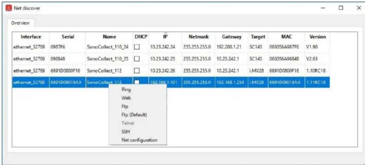
Figure 5 Context menu in the Netdiscover tool
Depending on the network settings of your PC or your general network infrastructure, the UDP port 8001 may be blocked. Then calls of the tool are blocked and the main window remains empty.
√ When a firewall in your network (also directly on the PC) is used, it is to create an appropriate firewall rule. It releases this port to be able to list the devices.
Ask your administrator about the firewall and network configuration.
If access via UDP broadcast is not possible, a list can be imported with the Import device list function in order to still be able to use all other functions via TCP.
Some important functions are described in more detail in the following subsections.
3.2 Network configuration
It is often necessary to adjust the network settings of the device for further work with the devices, especially when commissioning devices.
The command Net configuration from the context menu in the Netdiscover tool opens another tab for the network configuration. Thus, IP address, subnet mask or gateway address can be changed statically or DHCP can be activated to obtain these settings automatically from a DHCP server.
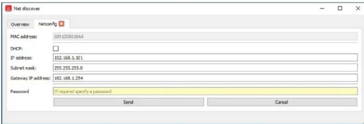
Figure 6 Network configuration via the Netdiscover tool
Modifications are only accepted with the password of the admin user.
3.3 Access to the web-based front end via HTTP
A web server is integrated on the SonoCollect devices. This enables the configuration of the devices via an integrated, web-based front end (see chapter 4).
Use the command Web from the context menu in the Netdiscover tool to quickly and easily call it from the default browser.
If the web-based front end does not open, please follow the instructions in section 4.13.
3.4 Access to the file system via FTP
The SonoCollect devices can be accessed via FTP to work directly on the file system level. Updates, special configurations and function extensions can be carried out (see chapter 10). The integrated FTP server of the devices supports both FTP and SFTP.
√ If access via FTP or SFTP is not possible, check especially the IP settings and the port release of port 21 for FTP and 22 for SFTP.
In case of access problems, ask your administrator.
The commands FTP and FTP (default) from the context menu in the Netdiscover tool start the WinSCP program and use the IP address of the selected device. Always use the selected device to have access via FTP. To use a secure SFTP, the context menu must be called without a selected device, then only the command FTP is available. Now select in the WinSCP window whether FTP, SFTP or SCP should be used.
The mode FTP (default) tries to log in with the default access data of the admin user, while in the mode FTP any access data can be entered.
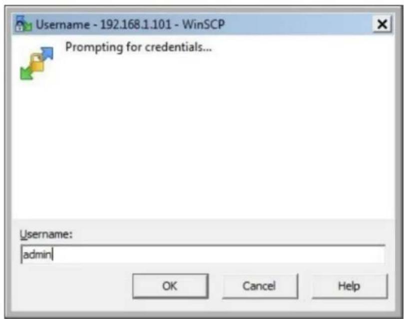
Figure 7 Entering user data when logging in via SFTP
√ If the access data of the admin user is modified, the use of FTP (default) is not possible.
WinSCP now establishes a secure SFTP or unsecure FTP connection. When a connection is established to a specific device with SFTP, its authenticity is checked using stored certificates. Normally, the SonoCollect devices receive an individual, self-signed certificate upon delivery. This certificate is usually classified as untrusted by your PC. Therefore, a security prompt with information about the device's certificate is
displayed. The user must actively trust this certificate for the connection to be established. The confirmed certificate is stored in the PC for future connections.
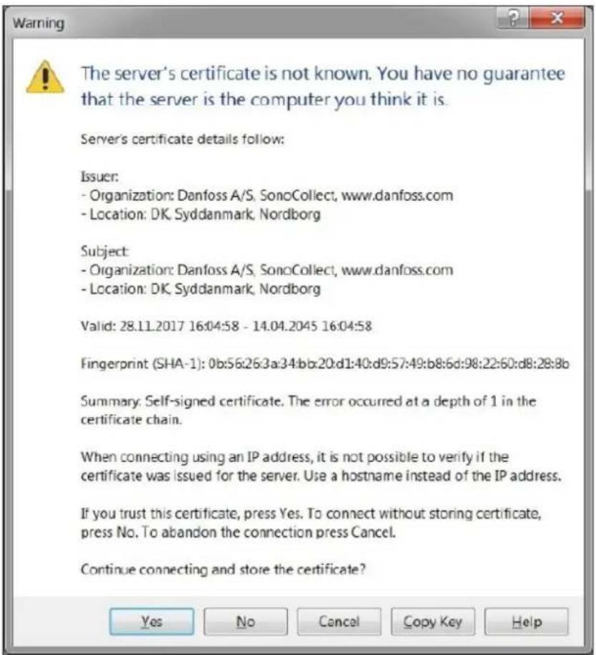
Figure 8 Safety query for the certificate of the device
WinSCP presents a two-part file browser view after successful login. This allows files to be uploaded to or downloaded from the device. File commands can be executed via a context menu (e.g. copying, renaming or editing. Drag&Drop for uploading and downloading is also supported.
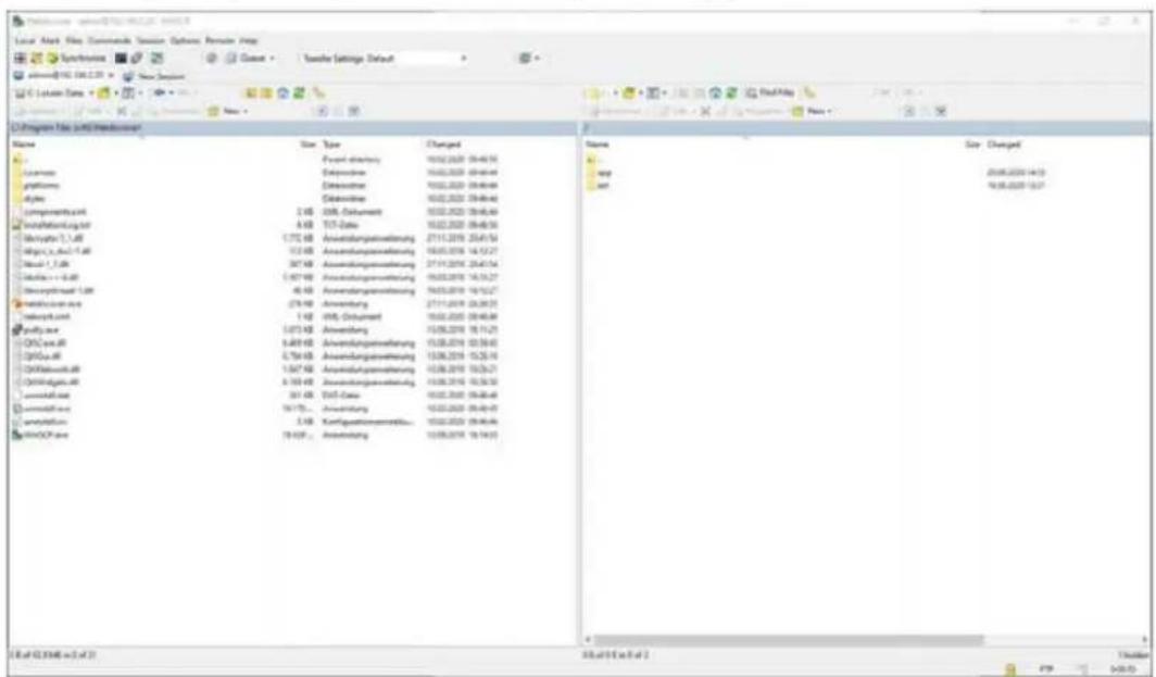
Figure 9 File Browser View in WinSCP
Changes to the files or the file system can limit the functionality of the system.
The standard access data in the delivery state are contained in the section 4.8.
3.5 Access to the command line via SSH
Access to the command line interface (CLI) of the device is suitable for maintenance purposes.
The command SSH from the context menu in the Netdiscover tool opens the integrated Putty client and establishes a connection to the device.
When a connection is established to a specific device with SSH, its authenticity is checked using stored certificates. Normally, the SonoCollect devices receive an individual, self-signed certificate upon delivery. This certificate is usually classified as untrusted by your PC. Therefore, a security prompt with information about the device's certificate is displayed. The user must actively trust this certificate for the connection to be established. The confirmed certificate is stored in the PC for future connections.
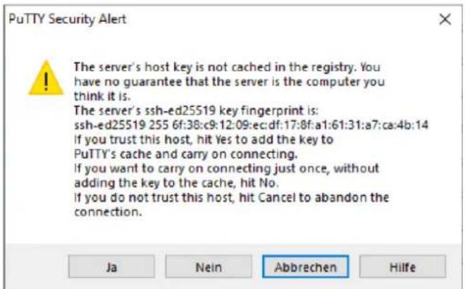
Figure 10 Safety query for the certificate of the device
Now the Putty client opens where the SSH access data of the admin user must first be entered. Then, the command line is ready for input via SSH.
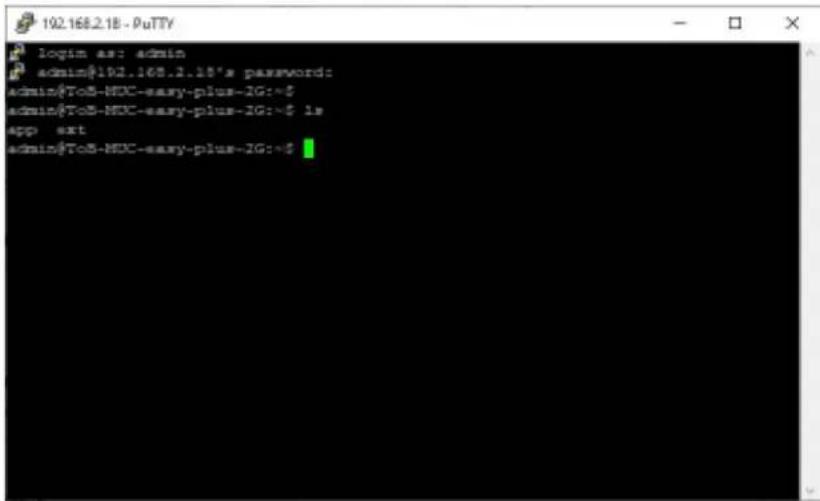
Figure 11 Command line in the Putty client
Inputs on the command line can restrict the functionality of the system.
The standard access data in the delivery state are contained in the section 4.8.
3.6 Mass management
Using this function it is possible to perform certain device configurations or firmware updates in parallel for all devices displayed in Netdiscover. This makes it possible, for example, to import an exported device configuration to other devices at the same time. Another example would be importing certificate files needed
on multiple devices to export meter data. A third and final example would be updating the application software on multiple devices in parallel.
The configuration or update should only be carried out explicitly for similar devices.
In this case mark the devices in Netdiscover on which you want to perform a parallel configuration or firmware update.
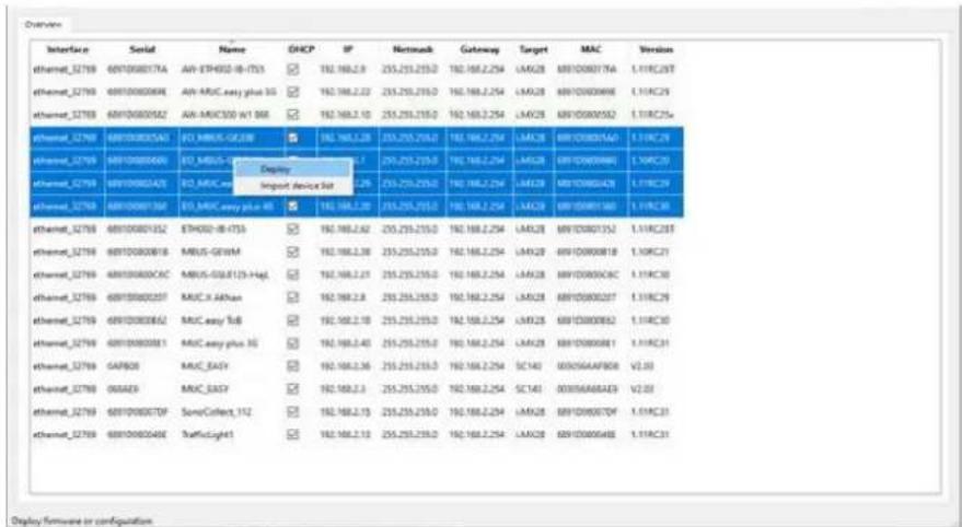
Figure 12 Selection and call of the mass management
The Deploy command from the context menu in the Netdiscover tool opens another tab for mass management.
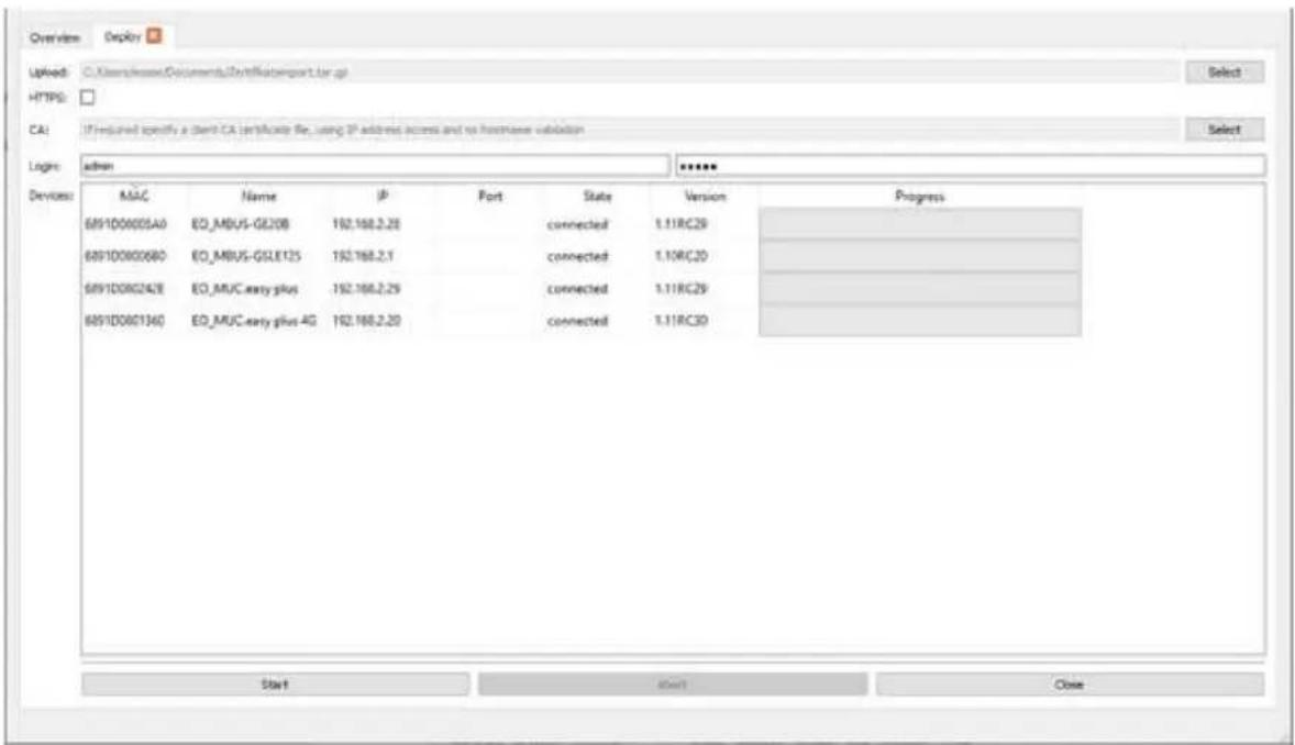
Figure 13 Mass management via the Netdiscover tool
The following input fields and buttons are available here:
- Upload: The configuration or update to be uploaded.
- HTTPS: Selection field whether HTTP or HTTPS should be used.
■ CA: The CA certificate to verify the client certificate of the devices for HTTPS-based work. - Login: User name and password for the admin user.
■ Start: Starts the process. - Abort: Cancels the process.
■ Close: Closes the mass management tab.
In the central part, there is a list view with information about the devices and the status/progress of the operation.
Only *.tar.gz archives are intended for uploading to the device.
The file is unpacked on the device after the upload, and processed, the device is then restarted.
3.7 Import of a device list
Devices cannot always be found automatically. Firewalls, routing settings or also the deactivation of the function Network discovery active in the Security tab (see section 4.7) are possible causes.
A device list can be imported in order to still be able to manage devices via the Netdiscover tool.
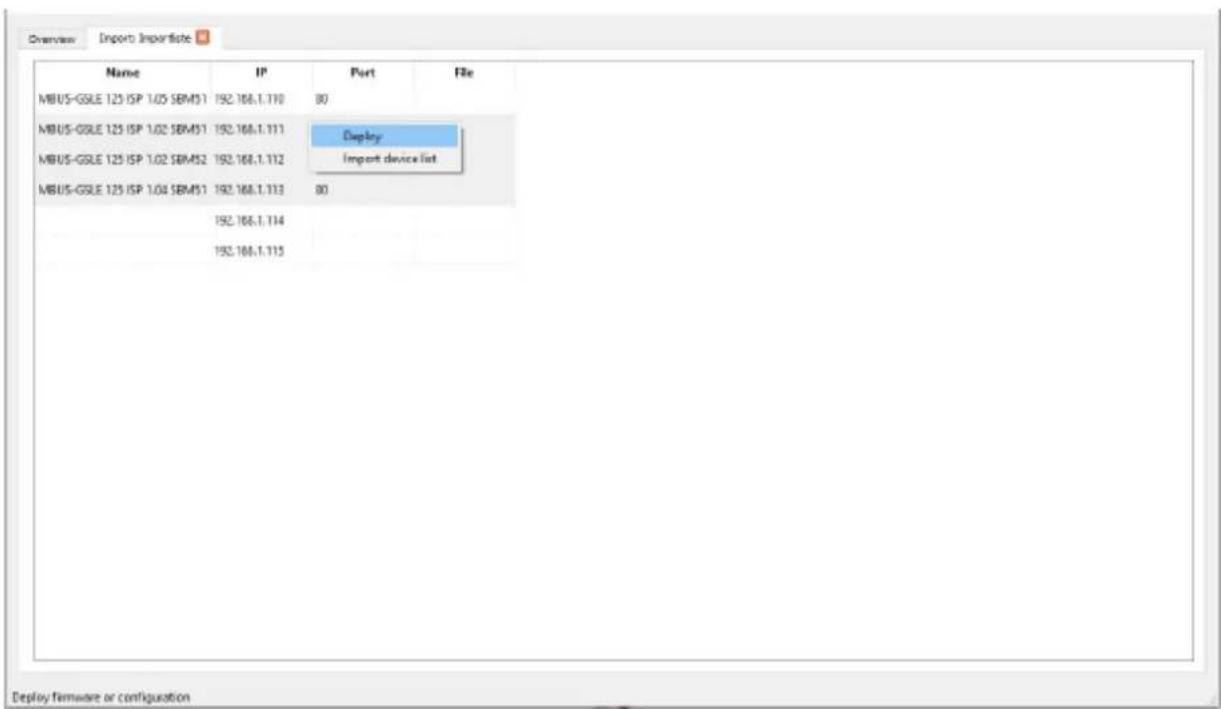
Figure 14 Viewing and using an imported list in the Netdiscover tool
A suitable CSV file must first be created before the actual import. A comma or semicolon can be used as a separator in the CSV file. The device data is entered here according to the following example to obtain the above list in the Netdiscover tool:
Port;Name;Password;Username;IP;File
80;MBUS-GSLE 125 ISP 1.05 SBM51;admin;admin;192.168.1.110;
80;MBUS-GSLE 125 ISP 1.02 SBM51;admin;admin;192.168.1.111;
80;MBUS-GSLE 125 ISP 1.02 SBM52;admin;admin;192.168.1.112;
80;MBUS-GSLE 125 ISP 1.04 SBM51;admin;admin;192.168.1.113;
;;admin;;192.168.1.114;
;;;192.168.1.115;
The header of the CSV file must be identical to the one above.
Only the IP column is mandatory. The other columns can be left empty and are set to default for special functions (port: 80, password: admin, user name: admin).
4 Web-based front end
Many products of Danfoss A/S, especially data concentrators and gateways for smart metering, have an integrated web server and provide a website for the configuration. The devices can be configured easily and in a user-friendly manner via this website. Device parameters, meter configuration as well as service services can be displayed or changed on this website.
This chapter contains an overview of the operating options via the web front end.
The use of some functions listed below depends on the product. A gateway for example does not have a report interface for data push or a cellular modem. This is indicated at the relevant point.
The web front end can be easily opened in the browser by entering the device IP address. Alternatively, right-click on the device in our Netdiscover tool (see chapter 3) and select the Web command in the context menu to call the browser.
We test the web front end in different browsers. We recommend the use of the Chrome and Firefox browsers for optimal viewing.
In the delivery state, the browser automatically logs the user into the website using the standard access data. The user "web" with the password "web" is stored ex works for this purpose. This user has full access to the website. This facilitates the initial commissioning.
If the default user ""web"" has been changed in the configuration via the tab User, for example by changing the password, the correct access data must be entered in order to log in. Then, the automatic login will not take place. A login window will then always appear:
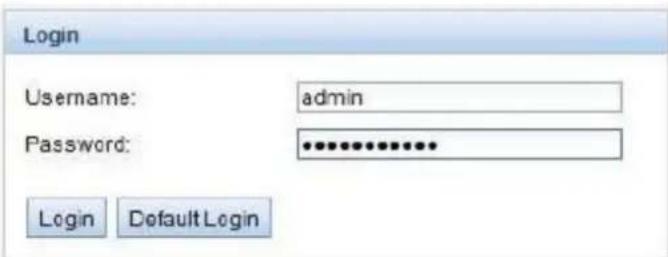
Figure 15 Login window
To change an already logged-in user (or default user), the Logout button in the top right can be selected.
The standard access data in the delivery state are contained in the chapter 4.7.
If the logged-in user has write access, the user must be logged out after the configuration has finished. If the connection remains active, no other work computers have write access to the web front end. Only one session with write access is possible at a time.
If a session is terminated without prior logout, e.g. by closing the browser window, it remains active for approx. 1 min. Afterwards it is automatically closed and write access is possible again.
The functions are subdivided into different tabs on the website of the device. So the clarity can be maintained despite the large number of parameters. All modifications in one of the tabs must be saved before changing tabs, otherwise the modifications will be lost. The functions and parameters of the individual tabs are described below.
4.1 Access via HTTPS
Normally the web front end is accessible via HTTP (port 80) as well as via HTTPS (port 443). Depending on the requirements, one of the services can be deactivated (see section 4.10).
Compared to HTTP, HTTPS offers both encryption and authentication methods and thus enables secure access to the devices in insecure networks.
The SonoCollect devices are delivered with certificates and keys in preparation for HTTPS access:
- app/keys/http_host_cert.: Self-generated certificate of the device to verify the identity of the device, server-side authentication
■ app/keys/http_host_key.: Private key of the device
The user can upload another certificate to the device to fully secure the communication and for mutual authentication.
- app/keys/http_host_ca.: Root certificate to check the client certificate of the browser and thus the identity of the client, client-side authentication
Based on these files, a protected identification and authentication of the communication partners takes place and a symmetric session key is negotiated.
Access to the web front end via HTTPS can be blocked by installing incorrect or invalid certificates.
√ Deactivating HTTPS or HTTP is only possible via the other access to the web front end.
√ Optionally, customer-specific certificates can be uploaded before delivery.
4.2 General tab
The General tab displays general properties of the device and its network configuration.
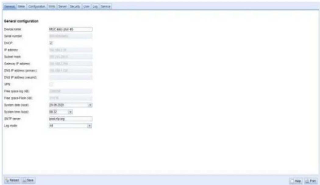
Figure 16 General tab
The following values can be viewed or changed here:
| Field name | Description |
| Device name | Name of the device (assignment in Netdiscover) |
| Serial number | Serial number of the device (MAC address), not editable |
| DHCP | Enable automatic network configuration |
| IP address | IP address of the device, not editable with DHCP |
| Subnet mask | Subnet mask of the device, not editable with DHCP |
| Gateway IP address | IP address of the default gateway, not editable with DHCP |
| DNS IP address (primary) | IP address of the primary DNS server, not editable with DHCP |
| DNS IP address (secondary) | IP address of the secondary DNS server, not editable with DHCP |
| VPN | Activates the OpenVPN client functionality |
| Free space log (kB) | Free space on the log area, not editable |
| Free space Flash (kB) | Free space on the application area, not editable |
| System date (local) | Current, local system date |
| System time (local) | Current, local system time |
| SNTP server | Address of the time server |
| Log mode | Detail depth of the log entries of the applicationNone: The application does not generate log entriesStandard: The application generates log entries for errors and warnings.All: The application generates log entries for all events |
Table 6: Fields in the General tab
The Save button is used to save the configuration. The Reload command loads the last saved values and resets the current changes.
If the network configuration is changed, the device is available under the new IP after the save process. All existing connections will be disconnected or logged in users will be logged out automatically.
Changing the network parameters of the device can restrict the accessibility. If the network parameters have already been set correctly by an administrator, they should not be changed.
The device is automatically reinitialized by setting the parameters via the SAVE button.
Date and time are always processed as UTC time (without time zone shift). When displayed on the website, the browser converts it according to the locally set time zone of the computer. In Central Europe, for example, this is Central European Time or Central European Summer Time. If a different time zone is set here, the time on the website will also be displayed accordingly.
The use of OpenVPN is described in the section 10.5.
4.3 Meter tab
The Meter tab displays an overview of the connected meters, and gives the user the possibilities of automatically searching for meters, adding meters manually, and configuring meters that are already present. The meter list can additionally be exported in this way.
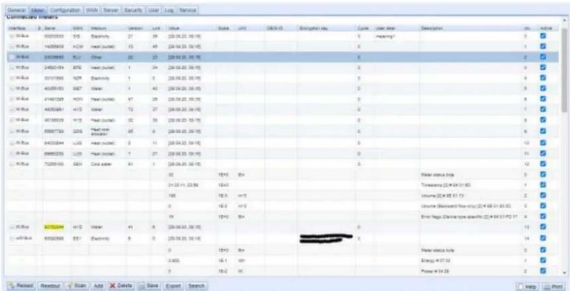
Figure 17 General tab
The meter list is displayed in tabular form. Meter entries and the corresponding meter value entries are displayed one below the other. The individual columns have the following meaning:
| Field name | Description |
| Interface | Interface to the meterM-Bus: wired M-Bus according to EN 13757-2/-3/-7 and OMSwM-Bus: wireless M-Bus according to EN 13757-4/-3/-7 and OMSDLDE: wired serial interface according to IEC 62056-21 or IEC 1107/61107S0: wired meter/pulse interface according to IEC 62053-31 or for simple contactorsSystem: Monitoring of internal measured values of the device |
| S (Status) | Shows the status of the meter or the meter value!: Meter or not all meter values can be read, meter value not currentE: Meter/meter value editedA: Meter/meter value added*: Meter value list limited (see Maximum value parameter count in Configuration tab) |
| Serial | Serial number of the meter (meter number, secondary ID) |
| MAN | Manufacturer of the meter (abbreviation), DLMS Flag-ID |
| Medium | Meter medium, see second column in Table 25 |
| Version | Version number of the meter |
| Link | Primary address of a meter (M-Bus) or reception field strength (RSSI) for wM-Bus |
| Value | Meter reading or measured value (unscaled) |
| Scale | Scaling factor (scientific notation) |
| Unit | Unit, see second column in Table 27 |
| OBIS-ID | OBIS code in the format X-X:X.X*X (X=0..255) |
| Encryption key | Key for encrypted wM-Bus meters |
| Cycle | Readout interval in seconds (at 0 the general readout cycle is used, see Configuration tab) |
| User label | User defined description of the meter value, this allows an application specific assignment. Allowed characters are: A-Z, a-z, 0-9, !,,\,\%,\/,(,)=-,?,+ and *. A comma is also allowed. Inadmissible are: , and ". When using the CSV format, the semicolon (or the corresponding separator) should not be used. |
| Description | Description of the meter value according to the second column in Table 26. The display of memory number, tariff, value type and raw data can be configured via the Description mode parameter in the Configuration tab. |
| Idx | Index/position of meter/meter value in the meter list |
| Register | Offset of the register set to the value when using the Modbus server |
| BACnet | Object number of the value when using the BACnet server |
| Active | Activates a meter or meter value for transmission to the server or logging. |
Table 7: Columns in the Meter tab
The meter configuration can be changed with the buttons in the lower area or through the context menu. Individual meters or meter values can be automatically searched for, created, deleted or changed according to the limitation of the interface used (M-Bus, wM-Bus etc.).
The meters or meter values in the list can be selected by a simple mouse click. A range can be selected with the
Duplicates of the serial number are marked in yellow for easier checking of the meters created. With the Search button the complete meter list can be searched for a search text. Hidden entries are also searched (meter values of closed maters).
Reload loads the last saved values, resets current changes, and correspondingly updates the meter values. In the delivery state, the device has an empty meter list. If meters are connected via the external interfaces of the device, the Scan button can start an M-Bus scan. The scan mode "M-Bus mode" is configured in the Configuration tab. More information on this can be found in chapter 6.1.1.
√ Depending on the mode and the number of connected meters, this may take a very long time.
The process can be interrupted with the Cancel button, whereby the meters already found are saved in the meter configuration. After the scan, the meter configuration is immediately accepted, and only has to be saved again after further changes. The scan can add meters to the existing meter list but no already configured meters are deleted or changed. Newly found M-Bus meters and their values are automatically activated after the scan or are assigned a Modbus address or BACnet number. The scan also permanently adds newly received wM-Bus meters to the configuration, provided that the parameter wM-Bus listen in the Configurationtab is activated. Since wM-Bus meters are not necessarily your own, they are not automatically activated, unlike the M-Bus. The list mode initially only lists all received meters without permanently saving their configuration.
√ The meter values of M-Bus and wM-Bus meters are arranged in the same order as the data in the M-Bus or wM-Bus protocol. This means that the meanings of the values can be directly compared with the data sheet of the relevant meter. Alternatively, the arrangement can be via the raw data of the meter values (see Description mode parameter in the Configuration tab in chapter 4.3).
√ The time stamps transmitted in the M-Bus or wM-Bus protocol are automatically assigned to the individual measured values, and therefore not listed in the meter list by default. The explicit representation of all time stamps can be manually activated via the configuration parameter MUC_SHOWTIMESTAMPENTRIES (chip.ini) (see chapter 8.4.1).
Newly received wM-Bus meters are deactivated by default, and have to be manually activated and saved in order to be transmitted in the server communication and log data. Non-saved wM-Bus meters are deleted after a restart.
Meters not found and meters not connected via interfaces which do not allow an automated search, can be added manually with the Add button or with Add meter in the context menu. More information on this can be found in chapter 6.1.3.
To configure individual meters or meter values, double click an entry or call the Editing window with the context menu item Edit. The field descriptions correspond to the columns of the meter list (see Table 7). Individual fields are activated or deactivated according to the interface.
Among other things, User label can be assigned to all entries here, so the meter or meter value can be assigned to a specific application. The (specific) read out interval of the meters can also be set via the parameter Cycle. The key required for decoding can also be set for wM-Bus meters in the Meter editing window.
S0 meters are internally processed with the number of pulses. The representation on the website in the value column is nevertheless scaled to provide better readability. The Scale column contains the pulse value and, in contrast to other meter interfaces, does not have to be additionally multiplied. If a value of 280.09 and a scaling of 1e-4 is displayed in the Meter tab, 2800900 pulses are recorded internally. However, this unscaled meter value appears analogously to those of other meters in the report data, such as the CSV of the XML.
With S0 meter values, the meter value itself can only be set in the Add or Edit window if the Set Value checkbox set is activated. The Set Value checkbox must be deactivated if a configuration does not change or overwrite the current meter value (e.g.: change of the user label). The input of a meter value is scaled.
Before an S0 meter value is saved, the input value is calculated back to the pulse value and rounded to whole pulses. Inaccuracies can result from the floating point data types.
The configuration can be finished with the Ok button or cancelled with the Cancel button.
For transmission and logging, individual meters and meter values can be directly activated or deactivated with the checkbox in the Active column. The meter values are automatically activated or deactivated by the configuration of a meter corresponding to the hierarchy. In the same way, an inactive meter is automatically activated if one of its meter values is activated. Multiple selected meters or meter values can be set with the context menu items Activate and Deactivate
All selected meters and meter values can be deleted with the Delete button or the context menu item with the same name. Deleted wM-Bus meters are then created again if the wM-Bus lists parameter in the Configuration tab is activated.
→ Individual meter values of an M-Bus or wM-Bus meter cannot be deleted.
The meter list is saved with the Save button.
Saving causes all the meter log data on the clipboard which have not yet been transmitted via the WAN interface to be lost. This also deletes the CSV log data of the current day because the column assignment it contains may have changed.
The Export button can be used to export the meter list as a CSV file or, if available, to download the data set of an active report at a certain point in time as a CSV or XML file.
√ Logged meter data can only be exported if data was recorded for the specified period, i.e. a report was active during this period (see section 4.6).
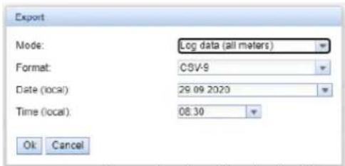
Figure 18 Exporting log data in the Meter tab
4.3.1 System meter
The system meter is a special function for providing device-specific operating parameters. These parameters are displayed via the system meter like normal meter values and can thus be monitored and evaluated.
These default values are available depending on the device:
| Field name | Description |
| Digital Input | State of the digital input, channel x |
| Digital output | State of the digital output, channel y |
| Operating time | Operating seconds meter |
| Reset meter | Meter of power supply interruptions |
| Temperature | Board temperature, not calibrated |
| Ampere | Bus load at M-Bus |
| On time | Time since last power supply interruption |
| CPU | Processor load |
| Memory | Free working memory |
| Memory <1> | Free memory of the application partition |
| Memory <2> | Free memory of the database partition |
| RSSI | Field strength of the mobile radio signal in dBm (-113 to -51 dBm, -114 corresponds to not connected) |
Table 8: Values of the system meter
| System | DINJSSS2 | SLV | Communication controller | 104 | 0 | [28.09.23, 00.04] | 0 | 75 | √ | ||||||
| 1 | 1E+0 | None | Digital input <1Fr | 0 | √ | ||||||||||
| 1 | 1E+0 | None | Digital input <2Fr | 1 | √ | ||||||||||
| 1 | 1E+0 | None | Digital input <3Fr | 2 | √ | ||||||||||
| 0 | 1E+0 | None | Digital output <1Fr | 3 | √ | ||||||||||
| 50.067.043 | 1E+0 | x | Operating time | 4 | √ | ||||||||||
| 54 | 1E+0 | None | Reset counter | 8 | √ | ||||||||||
| 46 | 1E+0 | Degree C | Temperature | 6 | √ | ||||||||||
| 1 | 1E-3 | x | Anpass | 7 | √ | ||||||||||
| 307.688 | 1E+0 | y | On box | 8 | √ | ||||||||||
| 45 | 1E+0 | % | CPU | 9 | √ | ||||||||||
| 5.100 | 1E+0 | 4Bytes | Memory | 10 | √ | ||||||||||
| 111.774 | 1E+0 | 4Bytes | Memory <1Fr | 11 | √ | ||||||||||
| 2.091.216 | 1E+0 | 4Bytes | Memory <2Fr | 12 | √ | ||||||||||
| -1 | 1E+0 | dSize | RSD | 13 | √ |
Figure 19 System meter in the Meter tab
The system meter can be extended by further meter values via scripts. More about this is described in the section 10.7.3.
4.4 Configuration tab
The Configuration tab enables parametrization of the meter interfaces of the device.
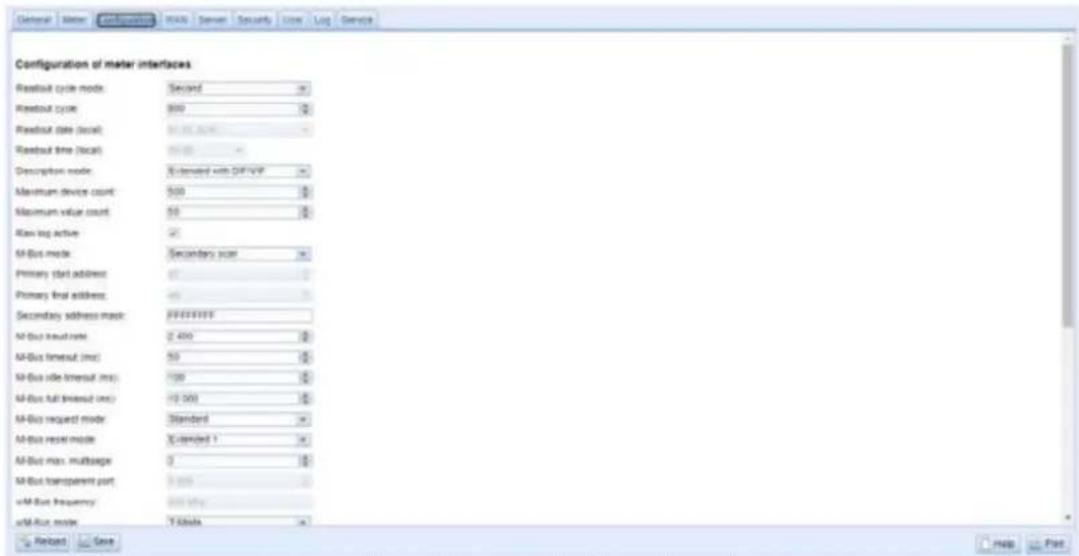
Figure 20 Configuration tab
The following parameters are available:
| Field name | Description |
| General readout and display parameters | |
| Readout cycle mode | Format of the specification of the standard readout cycle (for all meters, unless otherwise specified for individual meters in the Meter tab via the parameter Cycle).Second: Cycle of the readout is specified in secondsMinute: Cycle of the readout is specified in minutesHour: Cycle of the readout is specified in hoursDaily: Readout takes place daily at the specified timeWeekly: Readout takes place daily on the specified weekday and at the specified timeMonthly: Readout takes place monthly on the specified day of the month and at the specified timeQuarterly: Readout takes place quarterly on the specified day and month of the quarter and at the specified time (month 1..3 per quarter)Yearly: Readout takes place annually on the specified day and month and at the specified time |
| Readout cycle | Standard readout cycle of the meters (unit according to Readout interval mode in seconds, minutes or hours) |
| Readout date (local) | Day of readout for weekly to yearly specification of the standard readout cycle, depending on the interval format the month specification is used, the year specification is not used |
| Readout time (local) | Time of readout for daily to annual specification of the standard readout cycle |
| Description mode | Mode for displaying the meter value description on the website:None: No display of the meter value descriptionStandard: Display of the general meter value descriptionExtended: Expanded display (individual parameters are only displayed if they are not 0):Notation: Description [memory no.]Value typeExample: Energy [2] <1> maxExtended with DIF/VIF: Extended display additionally with DIF/VIF raw data:Notation: Description [memory no.]Value type # XX XX XX ...Example: Energy [2] <1> # 8C 11 04Extended with raw data: Expanded display also including the raw data of the complete meter value entry. Notation corresponds to Extended with DIF/VIF:Example: Energy [2] <1> # 8C 11 04 96 47 06 00DIF/VIF: Representation of the DIF/VIF raw dataRaw data: Display of the raw data of the complete meter value entry |
| Maximum device count | Limit for the number of meters during a scan (0: no limit). Already configured meters are not limited by this parameter. |
| Maximum value count | Limit for the number of meter values of a meter during a readout process (0: no limit). Already configured meter values are not limited by this parameter. |
| Raw log active | Activation oft he raw data loggings |
| Specific parameters to the M-Bus* | |
| M-Bus mode | Sets the first address for the primary search |
| Primary start address | Sets the last address for the primary search |
| Primary final address | Sets the search mask for the secondary search, 8 digits; wildcards are indicated by the letter "F"; missing characters are replaced by 0 from the left |
| Secondary address mask | Baud rate for M-Bus communication (300 - 19200 baud) |
| M-Bus baud rate | M-Bus timeout until first data is received (in ms) |
| M-Bus timeout | M-Bus timeout for detecting the end of communication (in ms) |
| M-Bus idle timeout | M-Bus timeout (total) for the reception of a data packet (in ms) |
| M-Bus full timeout | Limit for the number of meters during a scan (0: no limit). Already configured meters are not limited by this parameter. |
| M-Bus request mode | Mode of the M-Bus readout (REQ\_UD2):Standard: Readout process with REQ\_UD2Extended 1: Readout process with Get-All-Data (DIF/VIF 7F 7E) and REQ\_UD2Extended 2: Readout process with Get-All-Data (DIF 7F) and REQ\_UD2 |
| M-Bus reset mode | Mode of the M-Bus-Reset (before scan and readout operations):None: No resetStandard: SND_NKE to the primary address of the meter or broadcast for secondary addressing.Extended 1: SND_NKE to the primary address FD and a SND_NKE to the primary address of the meter or broadcast in case of secondary addressing.Extended 2: SND_NKE and an application reset to the primary address FD and a SND_NKE to the primary address of the meter or broadcast for secondary addressing. |
| M-Bus max. multipage | Limits the number of multipage requests |
| M-Bus transparent port | Network port for transparent M-Bus mode |
| Specific parameters to the M-Bus slave* | |
| M-Bus slave mode | Configuration of the M-Bus-Salve-Mode (M-Bus, TCP or UDP) or deactivation of the interface |
| M-Bus slave port | Network port for the M-Bus slave in case of TCP or UDP |
| M-Bus slave mode (2nd) | Configuration of the M-Bus-Salve-Mode (Instance 2, only TCP or UDP) or deactivation of the interface |
| M-Bus slave port (2nd) | Network port for the M-Bus slave (instance 2) |
| Specific parameters to the wM bus* | |
| wM-Bus frequency | Frequency band for communication with the wM-Bus meters |
| wM-Bus mode | Configuration of the wM-Bus communication mode for the OMS interface (T, S, C or C/T-Mode) or deactivation of the interface. |
| wM-Bus transparent mode | Configuration of the transparent wM-Bus communication mode (Transparent/TCP, Transparent/UDP) |
| wM-Bus transparent port | Network port for transparent wM-Bus mode |
| wM-Bus listen | Activates the detection and display of newly received wM-Bus subscribers. |
| Show encryption keys | Displays the keys in plain text after the save operation |
| Specific parameters to the wM bus (channel 2)* | |
| wM-Bus2 frequency | Frequency band for communication with the wM-Bus meters (channel 2) |
| wM-Bus2 mode | Configuration of the wM-Bus communication mode for the OMS interface (T, S, C or C/T mode) or deactivation of the interface (channel 2). |
| wM-Bus2 transparent mode | Configuration of the transparent wM-Bus communication mode (Transparent/TCP, Transparent/UDP) (channel 2) |
| wM-Bus2 transparent port | Network port for transparent wM-Bus mode (channel 2) |
| Specific parameters for pulse inputs* | |
| S0 mode | Selection for absolute or relative pulse counting or deactivation of the interface |
| Specific parameters for the serial interface* | |
| Serial mode | Operating mode of the serial interface (DLDE, Transparent/TCP or Transparent/UDP) or deactivation of the interface |
| DLDE baud rate | Baud rate for serial DLDE communication |
| DLDE data bits | Data bits for serial DLDE communication |
| DLDE stop bits | Stop bits for serial DLDE communication |
| DLDE parity | Parity for serial DLDE communication |
| DLDE mode | Flow chart for serial DLDE communication:Request: Request according to mode A or B according to IEC 62056-21 (constant baud rate)Request (C-Mode): Request and handshake according to mode C of IEC 62056-21 (constant baud rate)Push: Receiving spontaneous data sent by the meter |
| DLDE first timeout | Timeout until reception of first data (in ms) for serial DLDE communication |
| DLDE idle timeout | DLDE idle time out for receiving the first data of the meter (in seconds). In push mode, no data may be sent from the meter within this configured time (corresponds to the idle time). |
| DLDE full timeout | Maximum DLDE waiting time for reading a meter (in seconds) |
| DLDE transparent port | Network port for transparent DLDE mode |
*if device has this interface/function
Table 9: Fields in the Configuration tab
The configuration is saved with the Save button. The Reload command loads the last saved values and resets the current changes.
The device is automatically reinitialized by setting the parameters via the Save button.
4.5 WAN tab
The WANtab enables the configuration of the WAN connection for devices with integrated cellular modem. This is permanently set up when the device is restarted and is kept permanently active.
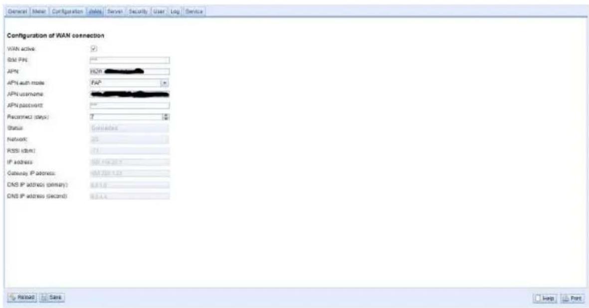
Figure 21 WAN tab
The following parameters are available:
| Field name | Description |
| WAN active | Activation of the WAN module |
| SIM PIN | PIN of the SIM card |
| APN | Name of the access point (APN) |
| APN auth mode | Authentication mode at the APN |
| APN username | User name for authentication at the APN |
| APN password | Password for authentication at the APN |
| Reconnect (days) | Interval in days after which a forced disconnection and re-establishment of the mobile radio connection is carried out (if no data is exchanged). Rationale numbers are also valid here, e.g.: 0.25. |
| Status | Status of the WAN connection (connected / not connected) |
| Network | Information about the mobile network |
| RSSI (dbm) | Display of the reception field strength in dBm (-113 to -51 dBm, -114 corresponds to not connected) |
| IP address | IP address in the WAN |
| Gateway IP address | Remote station in the WAN |
| DNS IP address (primary) | IP address of the primary DNS server, not editable with DHCP |
| DNS IP address (second) | IP address of the secondary DNS server, not editable with DHCP |
Table 10: Fields in the WAN tab
The necessary parameters for WAN connection should be provided by the mobile service provider of your SIM card.
Please check whether the mobile radio contract includes the expected quantity of data, otherwise increased costs or a blocking of the SIM card may follow.
Please check that the parameters are correct. The entry of incorrect parameters can lead to increased mobile radio costs or blocking of the SIM card.
If an invalid PIN is entered, it will be used only once per software startup. Thus, the remaining attempts for entering the PIN are not depleted and a new PIN can be entered via the website.
Changing the WAN configuration via an active mobile radio connection is not recommended, as the device may no longer be accessible after a changed or invalid configuration.
The configuration is saved with the Save button. The Reload command loads the last saved values and resets the current changes.
The device is automatically reinitialized by setting the parameters via the SAVE button. An existing WAN connection is terminated and re-established.
4.6 Server tab
The Server tab enables the parameterization of data provision to third-party systems. Ten independent instances can be defined here.
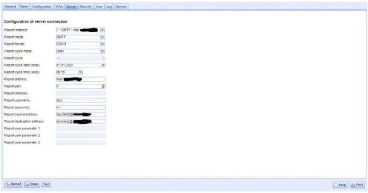
Figure 22 Server tab
The following parameters are available:
| Field name | Description |
| Parameters for data collectors with push functionality | |
| Report instance | Selection of the respective instance |
| Report mode | Operating mode or deactivation of the respective instance. There are these modes to choose from: TLS: Transmission via active data push over secured TCP channel to specified serverTCP: Transmission via active data push over unsecured TCP channel to specified serverSMTP: Transmission via active data push by e-mail to the specified addressFTP (client active): Transmission by active file transfer via FTP to the specified server (encrypted or unencrypted), in case of unencrypted FTP data connection is established from the serverFTP (client passive): Transmission by active file transfer via FTP to the specified server (encrypted or unencrypted), in case of unencrypted FTP data connection is established from the deviceMQTT: Transmission via active data push via MQTT client to the specified server/broker (encrypted or unencrypted)File: Generation of local files for later retrieval (data pull) by third party systemUser: User-specific connection procedure based on a Bash script (see section 10.7.210.7.2) |
| Report format | Data format for the transmission of the respective instance. Several CSV and XML formats are available. The User format uses a stored XSLT script to format the data (see 10.7.1). |
| Report cycle mode | Format of the indication of the transmission cycle of the respective instanceSecond: Cycle of the transmission is specified in seconds.Minute: Cycle of the transmission is indicated in minutes.Hour: Cycle of transmission is specified in hours.Daily: Transmission takes place daily at the specified timeWeekly: Transmission takes place daily on the specified day of the week and at the specified time.Monthly: Transmission takes place monthly on the specified day of the month and at the specified time.Quarterly: Transmission takes place quarterly on the specified day and month of the quarter and at the specified time (month 1..3 per quarter)Yearly: Transmission takes place annually on the specified day and month and at the specified time. |
| Report cycle | Transmission cycle of the respective instance |
| Report cycle date (local) | Day of transmission of the respective instance for weekly to yearly indication of the transmission cycle, depending on the interval format, the month indication is used, the year indication is not used. |
| Report cycle time (local) | Time of transmission for daily to annual Transmission cycle indication |
| Report address | Host address of the remote station or mail server (outgoing mail server) |
| Report port | Port number of the remote station to be connected |
| Report directory | Directory on the server |
| Report username | User name for server access |
| Report password | Password for server access |
| Report source address | Address of the transmitter (e-mail) |
| Report destination address | Destination address (e-mail) |
| Report user parameter 1 | User-specific parameters 1 (use of format or user mode) |
| Report user parameter 2 | User-specific parameters 2 (use of format or user mode) |
| Report user parameter 3 | User-specific parameters 3 (use of format or user mode) |
| Parameters for Modbus server | |
| Modbus mode | Operating mode: Modbus TCP or Modbus UDPIn the operating mode "Modbus TCP" up to 5 parallel connections by different Modbus TCP masters are possible. |
| Modbus port | Network port to which the remote station (the Modbus TCP client) must connect. |
| Modbus test | Dummy mode, where the test process image shown in Table 34 is activated, see section 11.4.2 |
| Modbus swap | Changes the Word order from MSW first (default) to LSW first (option checked), see section 11.4.3 |
| Modbus float only | Reduces the Modbus register layout from 10 registers/value to 2 registers/value and represents only the serial number of the meter and the floating point value of the corresponding meter value, see section 11.3 and section 11.4.4 |
| Modbus multi slave | Activates the multi-slave feature, where the data of a meter can be accessed as its own virtual Modbus slave under its own Modbus address, see section 11.4.5 |
| Parameters for BACnet server | |
| BACnet active | Activates the BACnet functionality globally |
| BACnet config network | Activates a second virtual network interface for the BACnet service |
| BACnet IP | IP address of the second virtual network interface for BACnet |
| BACnet netmask | Subnet mask of the second virtual network interface for BACnet |
| BACnet broadcast | Broadcast address of the second virtual network interface for BACnet |
| BACnet BBMD | IP address of a BACnet Broadcast Management Device (BBMD) for routing across local network boundaries |
| BACnet port | UDP port number of the BACnet service (default port: 47808) |
| BACnet device ID | ID number of the BACnet device |
| BACnet device name | Device name of the BACnet device |
| BACnet location | Location information of the BACnet device |
Table 11: Fields in the Server tab
Individual parameters that are required for the configuration are enabled corresponding to the operating mode of the server interface.
The configuration is saved with the Save button. The Reload command loads the last saved values and resets the current changes. The Test button allows die immediate transmission of the previously read-out data.
The device is automatically reinitialized by setting the parameters via the SAVE button.
Make sure that the system time is correct before you activate the report. If the system time is synchronized later, e.g. by NTP service, gaps may occur in the log. These gaps are then transferred to the target system in the form of empty files.
4.7 Security tab
The Security tab enables the parameterization of the network services of the device.
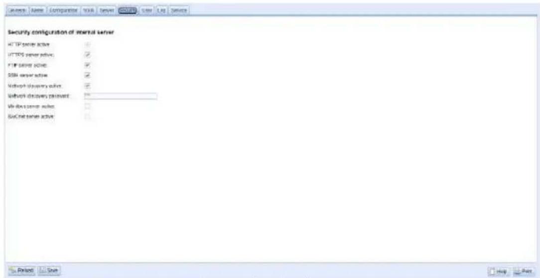
Figure 23 Security tab
The following parameters are available:
| Field name | Description |
| HTTP server active | Activates the internal HTTP server of the device, activation and deactivation only possible via HTTPS to be able to use the website. |
| HTTPS server active | Activates the internal HTTPS server of the device, activation and deactivation only possible via HTTP to be able to use the website. |
| FTP server active | Activates the internal FTP server of the device, if deactivated, no FTP access to the device is possible. |
| SSH server active | Activates the internal SSH server of the device (administrative access) |
| Network discovery active | Activates the internal discovery server of the device; if deactivated, the device is no longer displayed in the Netdiscover tool (see chapter 3). |
| Network discovery password | Password for setting the network parameters via the Netdiscover tool |
| Modbus server active | Modbus server active, read-only, depending on the Server tab |
| BACnet server active | BACnet server active, read-only, depending on Server tab |
Table 12: Fields in the Security tab
The configuration is saved with the Save button. The Reload command loads the last saved values and resets the current changes.
The device is automatically reinitialized by setting the parameters via the SAVE button. An existing WAN connection is terminated and re-established.
4.8 User tab
In the User tab different users with specific access rights to the website can be created.
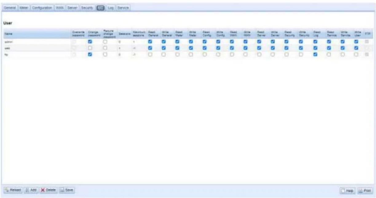
Figure 24 User tab
The following users are preconfigured in the delivery state:
| User name | Password | Comments |
| admin | admin | Administrative user that allows full access to all services of the device (HTTP, FTP, SSH, IP configuration). |
| web | web | Default user for the web interface. If a user with this name and password exists, the web interface automatically logs in with these access data. Otherwise, the user is prompted to enter the access data. When delivered, this user has full access to the website of the device. |
| ftp | ftp | User for unencrypted FTP access to the log directory ext/Log |
Table 13: User accounts on delivery
The existing configuration in the user table can be changed on the website:
| Field name | Description |
| Name | User name |
| Overwrite password | It is set if a (new) password has been set for the user in the editing window. |
| Change Password | Setting whether the user is allowed to change his password |
| Require change Password | Setting whether the user must change his password at the next login |
| Sessions | Display how often the user is logged in at the same time |
| Maximum sessions | Setting, how often the user may be logged in at the same time (-1=unlimited) |
| Read General | Read authorization for the General tab |
| Write General | Write authorization for the General tab |
| Read Meter | Read authorization for the Meter tab |
| Write Meter | Write authorization for the Meter tab |
| Read Config | Read authorization for the Configuration tab |
| Write Config | Write authorization for the Configuration tab |
| Read WAN | Read authorization for the WAN tab |
| Write WAN | Write authorization for the WAN tab |
| Read Server | Read authorization for the Server tab |
| Write Server | Write authorization for the Server tab |
| Read Security | Read authorization for the Security tab |
| Write Security | Write authorization for the Security tab |
| Read Service | Read authorization for the Service tab |
| Write Service | Write authorization for the Service tab |
| Write User | Read and write authorization for the User tab |
| FTP | Authorization of the user to log in via FTP (maximum 2 users) |
Table 14: Fields in the User tab
The user configuration can be changed with the buttons in the lower area or through the context menu. With the exception of the admin user, individual users can be created, deleted or changed.
The users in the list can be selected with a simple mouse click. A range can be selected with the
The Reload command loads the last saved values and resets the current changes.
When write access is activated on a tab, read access is also activated.
The admin user cannot be changed or deleted in the general user configuration. The administrator password can only be changed with the Change password button if the admin user is logged in.
Encrypted/secured FTP is usually SFTP not FTPS. When resetting, all configuration data and meter data are lost.
Only the admin user has full access to the file system of the device via encrypted FTP. The second FTP user can also access /ext/Log without encryption.
New users can be added via the button Add or via the context menu entry of the same name. The following window will open:
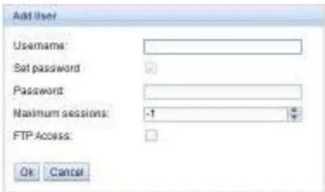
Figure 25 Input mask for adding a user
In addition to the user name and password, you can specify how often a user may log in at the same time (-1 no restriction). Besides the user admin another user can get FTP access to the device. The unencrypted FTP access only allows access to the log data of the device (directory: /ext/Log). This property can only be enabled at the time the user is created.
A separate FTP user (e.g.: ftp) allows a remote client to call the stored log data (manually or automatically), whereby it is not given access to other services or data of the SonoCollect 112.
To configure an already existing user, the Editing window can be called by double clicking its entry or via the context menu item Edit. This window has the same structure as the input window for creating a user. To reset the password of an existing user, the Set Password checkbox must be set. If the Set Password checkbox is not set, the user password is not changed or reset during this configuration process. A user password cannot be read.
The configuration can be finished with the Ok button or cancelled with the Cancel button.
The rights of an individual user are set directly in the user list. If a user has write access in a tab, he/she automatically also receives the right to display the tab (read access).
All selected users (with the exception of the admin user) can be deleted with the Delete button or the Context menu item with the same name.
The user configuration is saved with the Save button.
4.9 Log tab
The Log tab provides access to log information and status outputs. that facilitates the analysis of the behaviour and troubleshooting.
The scope of the log entries depends largely on the settings in the Log mode field in the General tab (see section 4.2).
For raw data logs on the meter interfaces, the Raw data log field in the Configuration tab must be activated (see section 4.4).
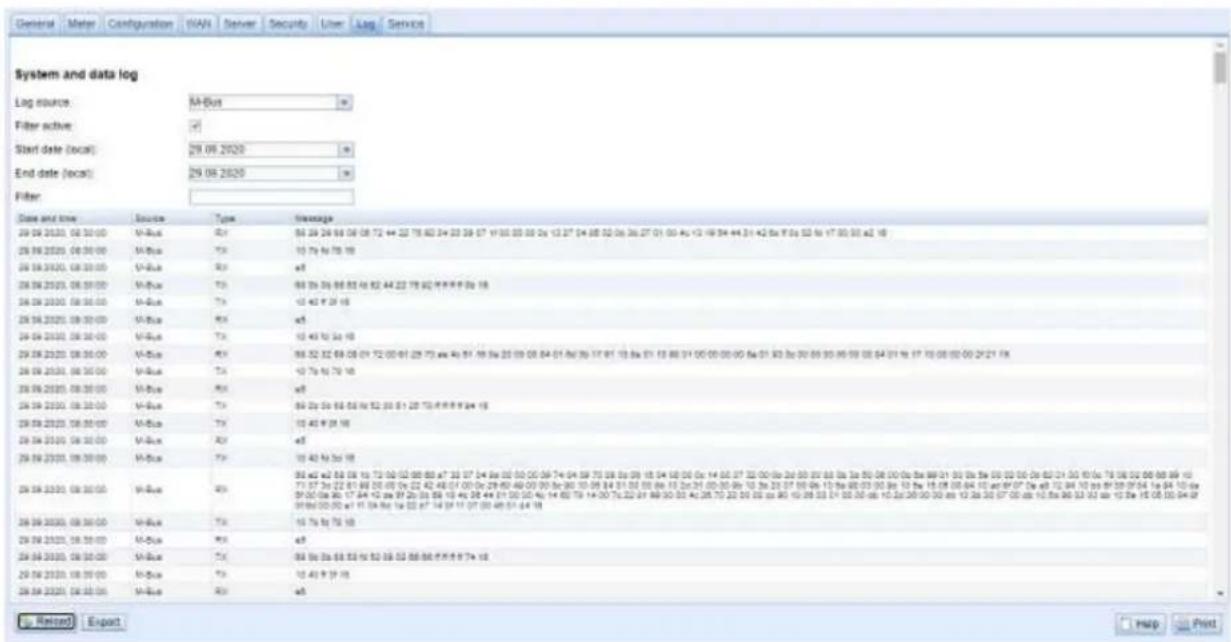
Figure 26 Log tab
The following options are available on the website:
| Field name | Description |
| Log source | Selection of the source of the log entriesSystem log: Display of the log entries of the system (Linux) and the applicationApplication: Display of the log entries of the applicationM-Bus: Display of the raw data of the M-Bus interface (if Raw data log is active in the Configuration tab)wM-Bus: Display of the raw data of the wM-Bus interface (if Raw data log is active in the Configuration tab)DLDE: Display of the raw data of the DLDE interface (if Raw data log is active in the Configuration tab) |
| Start date (local) | Start date for the time range of the log entries |
| End date (local) | End date for the time range of the log entries |
| Filter | Character string according to which the log is to be filtered (search for keyword or regular expression in Message column) |
Table 15: Fields in the Log tab
The Reload button updates the entries. The Filter button activates the search filter and the time range from the input fields and thus offers the possibility of targeted searches.
√ The raw data log can be searched for meter numbers with the special filter input serial=, e.g.: serial=12345678. All packages will then appear at the named meter.
If no log entries are displayed, please check the entries. If necessary, extend the specified time range or reset the filter.
The number of log entries displayed is limited to 500. Use the filter or the time range to reduce the entries.
The Export button downloads a compilation of all entries matching the filter as a CSV file from the device. This download may take some time depending on the size of the log.
4.10 Service tab
The Service tab enables maintenance work and provides related information or functions:
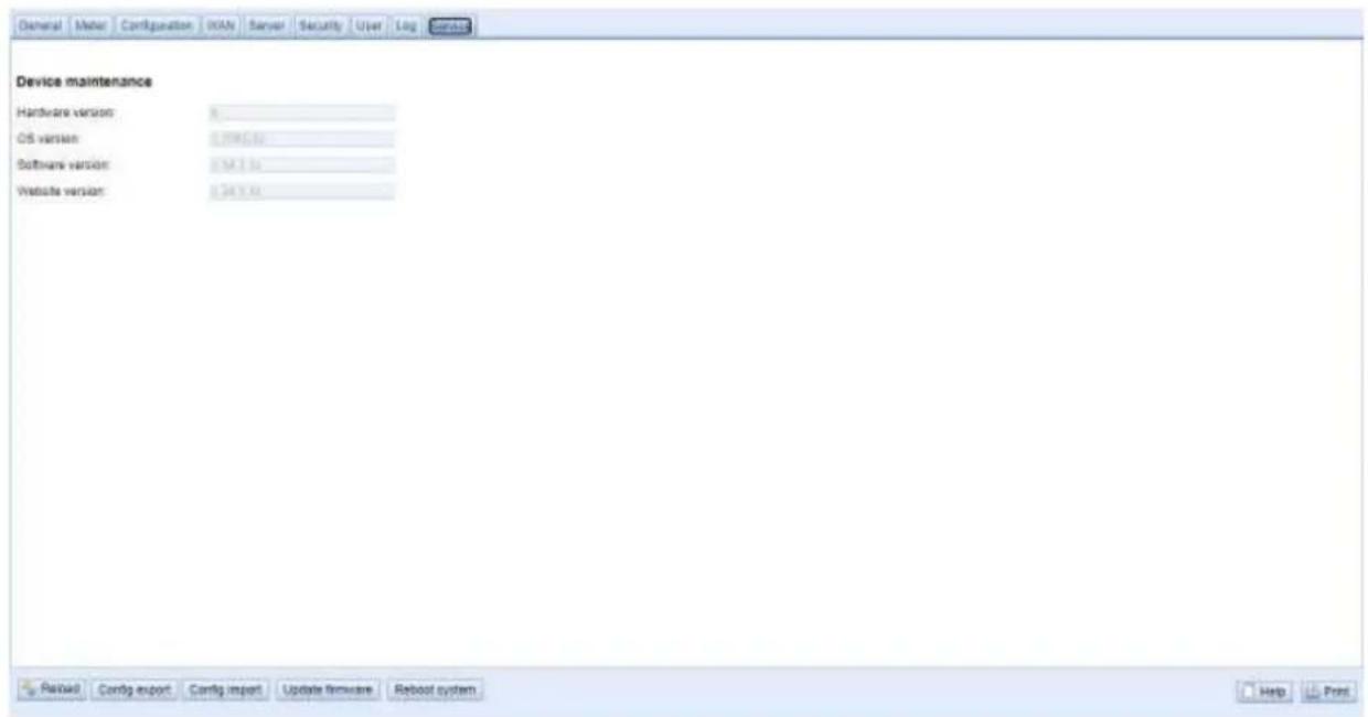
Figure 27 Service tab
| Field name | Description |
| Hardware version | Version of the hardware |
| OS version | Version of the operating system |
| Software version | Version of the software |
| Website version | Version of the website |
Table 16: Fields in the Service tab
The values are updated with the Reload button.
The buttons Config export and Config import are available to download the configuration of the device or to upload a configuration to the device.
When exporting the configuration, a selection box can be used to specify which data is downloaded from the device:
■ Certificates
■ Device configuration
■ Network configuration
■ Device name
■ Meter configuration
√ The Network configuration and the device name are part of the device configuration. If the device configuration is to be transferred to another device, it is recommended not to export the network configuration and the device name as well, since these settings are usually not to be transferred as well.
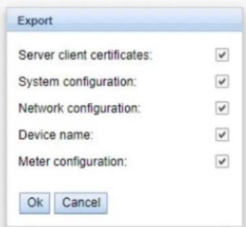
Figure 28 Configuration export options
The configuration is downloaded as *.tar.gz file. This archive is an extract from the file system of the device. It can be stored and modified for later use on another device. It can be used when transferring a valid configuration to a replacement device or when commissioning many similar devices.
When importing the configuration, a file selection window opens in which you can select a corresponding *.tar.gz file.
Pressing the buttons Update firmware also opens a file selection window. An update file can be selected in this window. Danfoss provides update files as *.enc files at regular intervals. These files can then be uploaded to the device. After a successful upload, the update process is carried out automatically and the device is then restarted.
The device can be restarted with the Reboot system button. All internal processes are shut down and re-initialized after the restart. Meter data (WAN interface) stored on the clipboard may be transferred after a restart. Use this button to adapt the configuration manually per FTP(S) adjustment or make an update.
4.11 Print page
A print version of the web page can be called up via the Print button (bottom right) to print view of the configuration or to export the device configuration via the clipboard. The website generates an additional print preview containing all available configured parameters according to the access rights. The print preview is automatically closed after a user has logged out (if not already closed).
√ The meter list displayed is also suitable for insertion into a table calculation.

SonoCollect 112
Configuration
| General configuration | |
| Device name: | SonoCollect_112 |
| Serial number: | 6891d08018aa |
| DHCP: | off |
| IP address: | 10.23.242.27 |
| Subnet mask: | 255.255.255.0 |
| Gateway IP address: | 10.23.242.1 |
| DNS IP address (primary): | |
| DNS IP address (second): | |
| Free space log (kB): | 2887268 |
| Free space Flash (kB): | 114667 |
| System date (local): | Mon Jan 13 2020 15:47:00 GMT+0100 (Romance Standard Time) |
| SNTP server: | ptbtime1.ptb.de |
| Log mode: | DEFAULT |
| Configuration of meter interfaces | |
| Readout interval mode: | SECOND |
| Readout interval: | 900 |
| Readout date (local): | Wed Jan 01 2020 00:00:00 GMT+0100 (Romance Standard Time) |
| Description mode: | 3 |
| Maximum device count: | 500 |
| Maximum value count: | 25 |
| Raw log active: | off |
| CSV log active: | on |
| Protocol version: | 8 |
| M-Bus mode: | SECONDARYSCANREVERSE |
| Primary start address: | 0 |
| Primary final address: | 250 |
| Secondary address mask: | FFFFFFF |
| M-Bus baud rate: | 2400 |
| M-Bus timeout (ms): | 2000 |
| M-Bus idle timeout (ms): | 100 |
| M-Bus full timeout (ms): | 10000 |
| M-Bus request mode: | 2 |
| M-Bus reset mode: | 0 |
| M-Bus max. multipage: | 3 |
| M-Bus transparent port: | 5000 |
| M-Bus slave mode: | DISABLED |
| M-Bus slave port: | 0 |
| wM-Bus frequency: | 868 MHz |
| wM-Bus mode: | C2_T2_OTHER_REQ |
Figure 29 Print page of the device, here the example SonoCollect 112
4.12 Supplied manual
Danfoss provides a manual as a PDF file on the devices. Use the Help button (on the right bottom) to access this manual.
4.13 Front-end troubleshooting
Access to the web server of the device via a standard web browser provides an easy and intuitive way to operate the device. Nevertheless, impairments or unwanted behaviour may occur.
A possible source of error is the browser cache, especially if several devices are operated under the same IP or an update has been applied. First terminate the web session with the Logout button and then completely reload the website to eliminate this source of error. Depending on the browser, this is done using a key combination, e.g.
4.13.1 Website or front end cannot be accessed
The website cannot be loaded or the error message "webservice not available" appears.
Check the IP settings of the device and your computer. The IP addresses should be in the same subnet or a route must be set up. If possible, change the IP addresses accordingly. Ask your administrator. Alternatively, you can use DHCP to give the device a valid IP address (see the Netdiscover tool in chapter 3). Two examples of a valid configuration:
■ Device: 192.168.1.101 (default IP), subnet mask: 255.255.255.0 → PC: 192.168.1.xxx (xxx = 0-254, except 101 and other already used IP addresses), recommended for direct connection 1:1 device and PC
- PC: 192.168.178.21, subnet mask: 255.255.255.0 → Device: 192.168.178.xxx (xxx = 0-254, except 1, 101 and 254 and other already used IP addresses), typical for connection to a router in the home network
Check whether the device is listed in the Netdiscover tool (see chapter 3). Check the general connectivity via ping test also from the Netdiscover tool.
Check whether a firewall blocks the data exchange or the routing is configured accordingly. Ask your administrator in this case.
In the case of an HTTPS connection, the browser may block the connection under certain circumstances. Confirm the stored certificate in the browser or "trust" the website and the certificate if you are sure to access the device.
If errors could not be rectified, please contact your local Danfoss support:
4.13.2 Login on website not possible
Check the user settings and rights for the website and the access data.
There may be another user already logged in and the number of active sessions may be limited. Then the login is also denied. In the User tab check the access data and the number of active sessions.
If errors could not be rectified, please contact your local Danfoss support:
4.13.3 All input fields or buttons are greyed out.
Greyed out buttons indicate a denied write access. A maximum of one user has write access.
Check whether another session is already active. This can also occur if a window in the browser is simply closed without logging out first. The session is then active for a short time. Log out again and wait about one minute. In the Usertab check the user rights and the number of active sessions.
Check whether the user has write access.
If errors could not be rectified, please contact your local Danfoss support:
4.13.4 Not all tabs are visible
Check the user's read access. Only the tabs for which the read access is active can be viewed. Check the user rights in the Usertab.
If errors could not be rectified, please contact your local Danfoss support:
4.13.5 Export of the log data of one/several meters is empty
Log data is only generated when a report is active in order to optimize the memory. Check in the Server tab whether a report is active.
Check the time range for the export. The time of the report must start before a valid readout. For example, to export the readout from 09/29/2020 13:15, the time for export should be set to 09/29/2020 13:10. The report then contains all readouts from 13:10 onwards until the end of the Report cycle in the Server tab of instance 1 or 15 minutes.
If errors could not be rectified, please contact your local Danfoss support:
4.13.6 The log is empty
Check the filter settings. If no filter is active, entries should always be available for the Log source System log. If not, this indicates a system-level misconfiguration. This can be remedied by the command solcmd config-partitions via the SSH console (see section 10.1.2).
Check whether the raw data log is active for the interfaces (see Configuration tab). Only then the raw data for the Log source e.g. M-Bus will be generated.
If errors could not be rectified, please contact your local Danfoss support:
5 Reading meters via M-Bus
A widely used interface for the automated acquisition of meter data is the wired M-Bus (Meter-Bus). This was originally specified in EN 1434-3. It received its own series of standards with EN 13757:
■ EN 13757-2 Communication systems for meters - Part 2: Wired M-Bus communication
■ EN 13757-3 Communication systems for meters - Part 3: Application logs
■ EN 13757-7 Communication systems for meters - Part 7: Transport and security services
Originally developed for heat meters, the M-Bus is now available for all types of consumption meters as well as sensors and actuators. Thus, it has a high value with regard to the collection of consumption data.
Essential features and advantages of the M-Bus are:
■ The M-Bus is a digital interface for the electronic reading of meter data.
- All consumption meters in a building/property can be operated and read on a single cable.
■ All consumption meters are addressable.
■ The readout is protected against transmission errors and is very robust.
■ The data is machine-readable and therefore easy to process.
■ The data are self-describing.
■ High readout rates are possible.
■ The M-Bus is manufacturer independent, there is a wide range of devices.
5.1 Signalling on the M-Bus
The M-Bus is a single master multiple slave bus. Therefore, a single bus master controls the bus and the data traffic on the bus, to which several slaves, i.e. meters, can be connected.
A second physical master is not allowed on the M-Bus.
The M-Bus uses voltage and current modulation on a physical level to transmit data. The master transmits telegrams by voltage modulation, the slave transmits telegrams by current modulation.
This is shown schematically in the following figure:
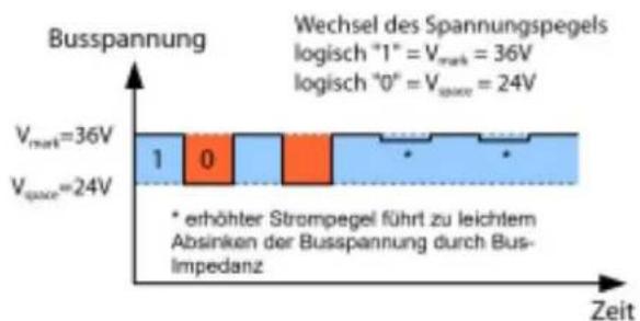
bar_stacked
| Time Segment | Value | | ------------ | ----- | | Lower Segment | 1 | | Upper Segment | 0 |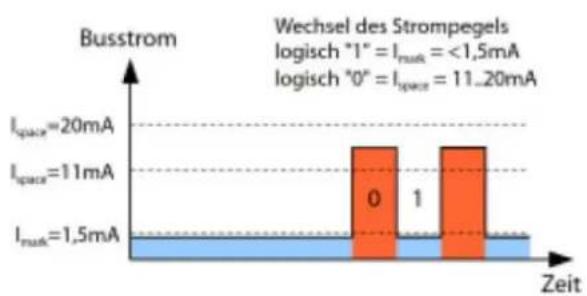
bar
| Time (Zeit) | Current (I-space) | Voltage (I_space) | | :--- | :--- | :--- | | 0 | 20mA | 11mA | | 1 | 11mA | 15mA | | 2 | 1.5mA | 1.5mA |Legend
Figure 30 Signalling with M-Bus
The M-Bus works according to the request-response principle, i.e. the master initiates the communication by a request/command which is then answered/confirmed by the slave. Spontaneous data transmission on the part of the slaves is not allowed.
Certain terms are used in the M-Bus standard. The basics of communication are taken from IEC 60870-5-101. Key examples are explained in the table below:
| Term | Description |
| ACK | Acknowledge, confirmation of a command, transmitted on the M-Bus as a single character telegram with content 0xE5. |
| Application reset | Reset of the application layer, command to reset the meter to the default state and to reset the meter for successive telegrams (multipaging). |
| Broadcast | Broadcast, command or request is sent to all slaves, special addresses 0xFE and 0xFF are used. |
| C field | Command field, code that describes the direction in which a telegram is exchanged and the meaning of the telegram. |
| Checksum | Check number for checking transmission errors, with the M-Bus the checksum results from the addition of the transmitted data (without telegram header, up to checksum). |
| Single character | One of the three telegram forms at the M-Bus with length of exactly 1 byte, telegram header and end from checksum and 0x16 are not present, used at the M-Bus for ACK. |
| FCB | Frame Count Bit, bit in the C-field, which is alternately set to 1 or 0 for successive telegrams, or for which successive telegrams can be retrieved when the bit changes. |
| I_mark | Transmit current of the slave at logical 1, usually 1 UL. |
| I_space | Transmit current of the slave at logic 0, usually 12.5-21.5 mA. |
| Short frame | One of the three telegram forms on the M-Bus with a length of exactly 5 bytes, are only sent from the master to the slave (e.g. commands and instructions), the telegram header is 0x10 and the telegram ends with checksum and 0x16. |
| Long frame | One of the three telegram forms on the M-Bus with variable length, the telegram header consists of 0x68 LL LL 0x68 (LL is the length of the telegram in each case), the telegram ends with checksum and 0x16. |
| Multipaging | M-Bus method of distributing large amounts of data over several logically consecutive telegrams, use of the FCB for sequence control. |
| Primary address | Link layer Address at the M-Bus, this is used to address the requests/commands, address range 0-250, special addresses 253 (0xFD), 254 (0xFE) and 255 (0xFF). |
| REQ-UD2 | REQUEST User Data type 2, request for consumption data, transmitted on the M-Bus by the master as a short frame telegram. |
| RSP-UD | ReSPonse User Data, response to request for data at the meter, transmitted on the M-Bus by the slave as a long frame telegram. |
| Secondary address | Worldwide unique identification number of the meter, consisting of manufacturer code, 8-digit serial number, medium ID and version number. |
| Slave select | Procedure for extending the address space to the secondary address of the meter, use of the SND-UD for selecting the meter via the application layer, then selected meter can be addressed via special address 0xFD. |
| Standard load | Defined quiescent current that a meter may draw from the M-Bus, according to the standard 1 UL=1.5 mA. |
| SND-NKE | SeND Normalization request, initialization command to the slave (reset FCB bit and selection), transmitted by the master as a short frame telegram on the M-Bus. |
| SND-UD | SeND User data, sending data or commands to the meter, transmitted by the master as a long frame telegram on the M-Bus. |
| U_mark | Mark voltage, upper voltage of the M-Bus signals at the master, representation of the logicalEN 1, idle state, usually 24-42 V. |
| U_space | Space voltage, lower voltage of the M-Bus signals at the master, representation of the logical 0, usually 12-30 V. |
| UL | Unit of standard load (see above) |
Table 17: M-Bus specific terms
5.2 Setup of the interface in the web front end
5.2.1 M-Bus mode
The parameter M-Bus mode in the Configuration tab activates the M-Bus interface and defines the basic range of functions:
■ Disabled
■ Secondary scan
■ Secondary scan reverse
■ Primary scan
■ Transparent/TCP
■ Transparent/UDP
The Transparent modes allow the physics of the M-Bus interface to be used via a TCP or UDP port. The data stream is thus forwarded from the M-Bus interface to an IP interface (network (LAN) or mobile radio (WAN)). The device then works in a similar way to an Ethernet M-Bus converter or even a mobile radio router with an M-Bus interface. The network port to be used is defined in the parameterM-Bus transparent port.
√ The transparent mode makes it possible to directly address meters via M-Bus interface. This requires appropriate M-Bus software on the host system. The device provides the physical connection. The transparent mode makes it possible to directly address meters via M-Bus interface.
5.2.2 Addressing, search and search range
A distinction is made between primary addressing and secondary addressing with the M-Bus.
The primary address is used for access control on the link layer. It is the basis of communication between master and slaves on the M-Bus and is used for communication in every telegram except the short frame. The secondary address is an extension of the addressing and additionally controls the access to the application layer.
The valid address range for the primary addresses is 0-250, whereby the address 0 is given a special position. According to the standard, this is only permissible for unconfigured meters (ex works). The address 253 is a special address for the use of secondary addressing, the addresses 254 and 255 are used for the broadcast with and without response. The addresses 251 and 252 are reserved.
The secondary address consists of 4 parts. These are the secondary ID (an 8-digit decimal number), the manufacturer ID (value of 0-65535), the medium ID (value of 0-255), and the version number (value of 0-255). Thus the address space is theoretically 115.19^*10^15 unique values.
The vendor ID can be converted to a vendor identifier, which is maintained by the DLMS User Association. An overview can be found here: https://www.dlms.com/flag-id/flag-id-list
The slave whose primary address matches the address in the request responds in case of primary addressing. This makes it possible to implement simple and short communication.
If the primary address is not unique during primary addressing, collisions and thus disturbed communication may occur, since several slaves are responding.
Secondary addressing, on the other hand, uses a so-called selection (slave select) on the basis of the secondary address in order to be able to address the meter with a matching secondary address via the primary address 253.
The non-matching meters deselect in the same step. Therefore, the process will be somewhat more complex, since an additional selection with confirmation is required. Communication takes a longer time. However, the address space is much larger, collisions do not occur, and more than 250 meters are possible on one bus system. In addition, commissioning is faster because not every meter has to be configured to a unique primary address.
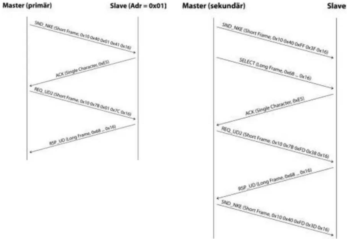
flowchart
graph TD
    A["Master (primär)"] --> B["SND_NKE (Short Frame, 0x10 0x40 0x01 0x41 0x16)"]
    B --> C["ACK (Single Character, 0xE5)"]
    C --> D["REQ_UD2 (Short Frame, 0x10 0x7B 0x01 0x7C 0x16)"]
    D --> E["RSP_UD (Long Frame, 0xb8 ... 0x16)"]
    E --> F["SND_NKE (Short Frame, 0x10 0x40 0xFD 0x3D 0x16)"]

    G["Master (sekundär)"] --> H["SND_NKE (Short Frame, 0x10 0x40 0xFF 0x3F 0x16)"]
    H --> I["SELECT (Long Frame, 0x68 ... 0x16)"]
    I --> J["ACK (Single Character, 0xE5)"]
    J --> K["REQ_UD2 (Short Frame, 0x10 0x7B 0xFD 0x38 0x16)"]
    K --> L["RSP_UD (Long Frame, 0xb8 ... 0x16)"]
    L --> M["SND_NKE (Short Frame, 0x10 0x40 0xFD 0x3D 0x16)"]
Figure 31 Example of primary and secondary addressing in comparison
Wildcards are also supported for secondary addressing. This allows, for example, the sole use of the 8-digit secondary ID for selection. The other parts are masked with the placeholder 0xFF (255) or 0xFFFF (65535). Individual digits of the secondary address can also be masked with 0xF (16).
√ The M-Bus uses the BCD display for the Secondary ID, therefore the 8-digit decimal number is encoded by an 8-digit hexadecimal number. Special functions can be represented by the characters A-F per digit, but only the F is used, as a placeholder at the respective digit.
The placeholders are also the basis of the secondary search. This divides the secondary address space piece by piece by means of the placeholders and checks whether there are meters in the respective part. If so, this part is further subdivided until there is only at most one meter per part or further subdivision is not possible. The classic procedure here is to mask the manufacturer ID, medium ID and version number and search the 8-digit number range of the secondary ID.
The range 000000-999999 is divided by sending the selection to 0FFFFFFF, i.e. selecting all meters with a 0 at the top of the Secondary ID. A query is then sent to the selected meters using the primary address 253. If no response is received, no meter is in this range the lowest unmasked digit can then be incremented and it continues with 1FFFFFFF. If you get an undisturbed response, there is only one meter in this range and you can save this meter as found and count up the lowest unmasked digit and continue searching. If one receives a disturbed response or collision, one moves to the next still masked location and traverses it from 0 to 9. Due to the variability of the process depending on the meters and the distribution of the secondary ID in the address space, it is difficult to estimate in advance what time a search will take.
Primary search, in contrast, is very direct and determinate. Every primary address is requested and depending on a valid answer a meter is then stored as found or not. Thus, 250 queries are always necessary for a complete search.
The parameters Primary start address and Primary final address in the Configuration tab limit the primary search by specifying the start and end. The parameter Secondary address mask is used to mask the secondary ID, so that the search can be limited to certain areas. For example, a mask 33FFFFFF limits the search to all meters whose secondary ID begins with 33.
5.2.3 M-Bus baud rate
The parameter M-Bus baud rate in the Configuration tab is used to configure the bit display on the M-Bus interface. The baud rate essentially determines the speed of the data transmission.
√ M-Bus usually uses 2400 baud. 300 baud and 9600 baud are other common baud rates. Many meters detect the baud rate automatically.
√ The other parameters for the bit display of the M-Bus interface are fixed to 8 data bits, even parity and 1 stop bit (8-E-1).
5.2.4 M-Bus timeouts
The M-Bus interface uses with M-Bus timeout, M-Bus idle timeout and M-Bus full timeout three different timeouts (in transparent mode only the M-Bus idle timeout), which can be parameterized in the Configurationtab.
The M-Bus idle timeout specifies what time the M-Bus interface must be "idle", i.e. no data is sent/received, in order to detect the end of a telegram (end of communication). It is mainly used for package formation of the M-Bus data stream, i.e. the assignment of incoming data to a logical unit (data packet).
The M-Bus timeout specifies what time it takes to wait for a response from the meter. If no data is received within this time from the request, the readout attempt is aborted.
The M-Bus full timeout indicates the latest time at which reception is interrupted in order to process the received meter data. This parameter also terminates reception if the M-Bus idle timeout is not reached because data is continuously received (without idle, e.g. in the event of faults).
5.2.5 M-Bus request mode
By default the readout is done via the command REQ_UD2 which the master sends to the meter. This is answered by the meter with the RSP_UD, which contains the usual meter data (consumption data).
In addition, the parameter M-Bus request mode in the Configuration tab can be used to explicitly select the data to be read out before the actual readout. In case of the SonoCollect devices there is the possibility to send a so-called global readout request to the meter before the actual query. For this purpose a SND_UD is sent to the meter. The user data then consists of only one or two characters. There are two implementations with the same function, depending on the manufacturer one or the other is supported:
■ User data consisting of 2 bytes: DIF=0x7F, VIF=0x7E → M-Bus request mode Extended 1
- User data consisting of 1 byte: from DIF=0x7F → M-Bus request mode Extended 2
√ This command is usually not necessary, because all meter values are transmitted by default with the normal query.
The use may result in a change of the data record of the meter
5.2.6 M-Bus reset mode
With the M-Bus there are several variants and applications of a reset. A distinction is made between:
■ Link layer reset → SND_NKE
■ Application layer reset → Application reset mittels SND_UD
The link layer reset is only responsible for initializing the communication flow of the link layer according to EN 13757. Therefore, it resets the selection based on the secondary address, deselects the meter, and also resets the FCB mechanism (see section 5.2.7).
The application layer reset, on the other hand, resets the application in the meter (or the communication application).
The parameter M-Bus reset mode in the Configurationtab can be used to set which of the resets and to which address it is sent. The resets are then sent at the beginning of a search run and before each readout of a meter:
■ None: Neither a link layer reset nor an application layer reset is sent.
- Standard: A link layer reset is sent to the broadcast address 0xFF and, in the case of primary addressing, also to the respective primary address.
- Extended 1: A link layer reset is explicitly sent to the selection address 0xFD and then the link layer resets of the standard mode.
■ Extended 2: After the link layer reset to the selection address 0xFD an application layer reset is sent to the broadcast address 0xFF and then the link layer resets of the Standard mode.
5.2.7 M-Bus multipaging
If the data of a meter do not fit into a single telegram (maximum 255 bytes user data), there is the possibility to split these data into several logically connected, consecutive telegrams. The FCB mechanism according to IEC 60870-5-2 is used for the readout sequence. Danfoss calls this process "multipaging".
In order to call possibly existing telegrams of the meter, the master must switch the FCB with each new request REQ_UD2 to inform the meter to send the following telegram. If the master does not switch the FCB, the meter always responds with the same telegram again. The REQ_UD2 then alternately have a C field of 0x5B or 0x7B.
The parameter M-Bus max. multipage in the Configuration tab restricts the maximum number of interrelated telegrams to a number. Especially in the case of meters with a lot of data (e.g. load profiles, reference date series), the readout time can be shortened and less relevant values are not read out at all.
It is sufficient to use the first telegram of the telegram sequence for most applications.
The M-Bus does not provide a mandatory mechanism to directly access certain telegrams of the sequence. As a rule, the procedure always starts from the first telegram. At least all relevant telegrams must be called.
An "Application reset" to the meter leads to a reset to the first telegram of the sequence.
5.3 M-Bus troubleshooting
5.3.1 Physical troubleshooting
In order to determine why meters on the M-Bus do not respond or are not found during the search, a physical check of the M-Bus network is usually suitable. It can be relatively easy to basically determine whether the M-Bus is at least correctly wired.
A standard multimeter is sufficient for simple measurement. The most important measurement is the voltage measurement between both M-Bus lines. The voltage measurement shows that:
■ the M-Bus master correctly supplies the bus: approx. 30-40 V are present
■ the meter is correctly connected to the M-Bus: approx. 30-40 V are present
■ the voltage drop is not too high: the voltage at the master is only slightly higher than at the meter
- the telegrams of the master arrive at the meter: when sending, the value in the display of the multi-meter 'wobbles'.
Another important measurement is the current measurement on the two M-Bus lines. The current measurement shows that:
■ the load on the M-Bus is in a valid range: approx. (number of meters)*1.5 mA flows
■ no external currents are present: current through both lines is identical
- the telegrams of the meter arrive at the master: the value in the display of the multimeter 'wobbles' in case of the response
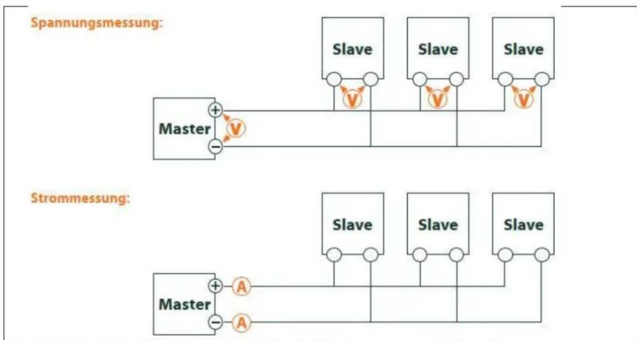
flowchart
graph TD
    subgraph Spannungsmessung
        A["Master"] --> B["Slave"]
        B --> C["Slave"]
        C --> D["Slave"]
        D --> E["Slave"]
        E --> F["Slave"]
        F --> G["Slave"]
    end
    subgraph Strommessung
        H["Master"] --> I["Slave"]
        I --> J["Slave"]
        J --> K["Slave"]
        K --> L["Slave"]
        L --> M["Slave"]
        M --> N["Slave"]
        N --> O["Slave"]
        O --> P["Slave"]
        P --> Q["Slave"]
        Q --> R["Slave"]
        R --> S["Slave"]
        S --> T["Slave"]
        T --> U["Slave"]
        U --> V["Slave"]
        V --> W["Slave"]
        W --> X["Slave"]
        X --> Y["Slave"]
        Y --> Z["Slave"]
        Z --> AA["Slave"]
        AA --> AB["Slave"]
        AB --> AC["Slave"]
        AC --> AD["Slave"]
        AD --> AE["Slave"]
        AE --> AF["Slave"]
        AF --> AG["Slave"]
        AG --> AH["Slave"]
        AH --> AI["Slave"]
        AI --> AJ["Slave"]
        AJ --> AK["Slave"]
        AK --> AL["Slave"]
        AL --> AM["Slave"]
        AM --> AN["Slave"]
        AN --> AO["Slave"]
        AO --> AP["Slave"]
        AP --> AQ["Slave"]
        AQ --> AR["Slave"]
        AR --> AS["Slave"]
        AS --> AT["Slave"]
        AT --> AU["Slave"]
        AU --> AV["Slave"]
        AV --> AW["Slave"]
        AW --> AX["Slave"]
        AX --> AY["Slave"]
        AY --> AZ["Slave"]
        AZ --> BA["Slave"]
        BA --> BB["Slave"]
        BB --> BC["Slave"]
        BC --> BD["Slave"]
        BD --> BE["Slave"]
        BE --> BF["Slave"]
        BF --> BG["Slave"]
        BG --> BH["Slave"]
        BH --> BI["Slave"]
        BI --> BJ["Slave"]
        BJ --> BK["Slave"]
        BK --> BL["Slave"]
        BL --> BM["Slave"]
        BM --> BN["Slave"]
        BN --> BO["Slave"]
        BO --> BP["Slave"]
        BP --> BQ["Slave"]
        BQ --> BR["Slave"]
        BR --> BS["Slave"]
        BS --> BT["Slave"]
        BT --> BU["Slave"]
        BU --> BV["Slave"]
        BV --> BW["Slave"]
        BW --> BX["Slave"]
        BX --> BY["Slave"]
        BY --> BZ["Slave"]
    end
Figure 32 Troubleshooting the M-Bus by measurement with multimeter
5.3.2 M-Bus meters are not found
Check the cables between the device and the meter, and replace faulty cables if necessary. While the device is switched on, measure the M-Bus voltage (approx. 30 to 40 V) between the two M-Bus connections on the device and also on the meter.
Ensure that the M-Bus interface is activated via the parameter M-Bus mode on the web page in the Configuration tab and that the search mode configured therein (secondary or primary) is supported by the meter(s).
Work with search masks or a restriction of the search range to search the M-Bus step by step (e.g.: Primary start address, Secondary search mask).
The M-Bus query can also be adapted with the following parameters:
■ M-Bus request mode
■ M-Bus reset mode
Scan again with a different M-Bus baud rate (300, 2400 or 9600) or lengthen the timeout.
Remove other meters (if any) to eliminate a possible source of error.
If another M-Bus meter (possibly the same type) is available, you can perform another communication test with the other meter to localize the source of error.
The number of attempts for an M-Bus request can be increased via the parameter MBUS_MAXRETRY in the extended configuration of the device by the use of file app/chip.ini (see section 10.3) This makes it easier to find meters that do not answer every query. The default value here is 3. Start the search again.
Collisions can occur if the same primary or secondary addresses occur more than once during the search procedures. An address duplication is common with primary addressing. Therefore we recommend secondary addressing. In such cases collisions can also occur, since due to the default value of the parameter MBUS_SELECTMASK=14 (see section 10.3), only the 8-digit serial number is searched during the search.
Activate the raw data log with Raw data log in the Configuration tab (see section 4.4). The communication process can be analyzed very well using this raw data log.
If errors could not be rectified, please contact your local Danfoss support.
M-Bus meters are found, but do not show any data
Some meters contain incorrect secondary address or encryption information in the data packet. As a result, they may not be addressable for readout or may be processed incorrectly. Parts of the secondary address can be masked and thus meters can be read after all using the parameter MBUS_SELECTMASK (see section 10.3) The parameter MBUS_DISABLEDECRYPTION=1 (see section 10.3) can also be used to disable the unusual decryption of M-Bus packets if they pretend to be encrypted.
Restart the search or perform a readout.
If errors could not be rectified, please contact your local Danfoss support.
5.3.3 The search takes a long time
The search for M-Bus meters can take a long time under certain circumstances, quite longer than 1 h, especially with secondary search and ascending meter serial numbers.
Work with search masks or a restriction of the search area to search the M-Bus step by step.
Decrease the value of the parameter MBUS_MAXRETRY in the file app/chip.ini (see section 10.3) or reduce the timeouts.
Use a different search mode in the Configuration tab (see section 4.4). In particular, the reverse secondary search Secondary scan reverse may help in this case. Then start the search again.
In the event of faults on the M-Bus, long search runs may also occur, since faults are processed as receive packets and a meter is thus assumed in each search step.
If errors could not be rectified, please contact your local Danfoss support.
5.3.4 Device restarts during search
For safety reasons, the device operates with an internal watchdog, which is intended to prevent the device from becoming unreachable. If the search takes a long time, this watchdog may cause the device to restart. If the search takes a long time, it is recommended to increase the value of the parameterWATCH-DOG_SCAN in the file app/chip.ini (see section 10.3). Then start the search again.
There may also be severe collisions on the bus under certain circumstances, e.g. if all meters respond at the same time. In exceptional cases, these severe collisions and the associated large increase in current can lead to the device restarting. Work with search masks or a restriction of the search range to search the M-Bus step by step (e.g.: Primary start address, Secondary search mask). If necessary, divide the bus for the search, and search the bus sections one after another.
If errors could not be rectified, please contact your local Danfoss support.
6 Reading meters via wM bus
A widely used interface for the automated acquisition of meter data is the wireless M-Bus (wM-Bus, wireless M-Bus, wireless Meter-Bus). Like the wired M-Bus, it is specified in the series of standards EN 13757:
■ EN 13757-4 Communication systems for meters - Part 4: Wireless M-Bus communication
■ EN 13757-3 Communication systems for meters - Part 3: Application logs
■ EN 13757-7 Communication systems for meters - Part 7: Transport and security services
The wM-Bus is the extension of the M-Bus for use via a radio system. Protocol and mechanisms are therefore very similar, deviations are due to the speciality of radio. Thus, it has a high value with regard to the collection of consumption data.
Essential features and advantages of the wM-Bus are:
■ The wM-Bus is a digital interface for the electronic reading of meter data.
■ All consumption meters have a unique identifier.
■ The readout is protected against transmission errors and is very robust.
■ The data is machine-readable and therefore easy to process.
■ The data are self-describing.
■ High readout rates are possible.
■ The M-Bus is manufacturer independent, there is a wide range of devices.
■ The data can be encrypted and is protected against replay attacks.
- The used frequency of 868 MHz offers sufficient penetration in the building at low transmission power.
■ Repeaters can be used to extend the radio network.
6.1 Signalling via wM bus
The wM-Bus is a radio system that operates mainly in the SRD band at 868 MHz. Other frequencies, such as 433 MHz or 169 MHz are also defined. The used and allowed frequency differs between continents and countries.
Technically, the wM bus uses frequency modulation (FSK). The physical parameters and the modulation type depend on the mode of the wM bus. There are different modes:
■ S-Mode: Stationary mode: Mode originally intended for fixed installations, declining importance
- T-Mode: Frequent transmit mode: Mode originally intended for walk-by application, frequently used
- R-Mode: Frequent receive mode: Special mode for reception on multiple radio channels simultaneously
■ C-Mode: Compact mode: Energy-optimized variant similar to T-mode, growing importance
■ N-Mode: Narrow band VHF: Special mode for the use of 169 MHz
■ F-Mode: Frequent receive and transmit mode: Special mode for the use of 433 MHz
The modes S, T, C and N are defined as unidirectional (e.g. S1 or T1) as well as bidirectional (e.g. S2 or T2). The R and F modes are always bidirectional. In the context of the meter interface, unidirectional means that the meter only transmits and does not receive. Therefore, no data can be sent to the meter. The reception time window in the meter is open for only a very short time after a telegram has been sent due to the battery in case of bidirectional communication. The other side must then respond within this very short time to keep the receiver active, otherwise it will be switched off again.
The SonoCollect devices are intended for unidirectional operation and are therefore only used to receive meter data.
6.2 Troubleshooting the wM bus
6.2.1 wM-Bus meters are not found
Ensure that the wM-Bus interface is configured for T-, C-, C/T- or S-Mode via the parameter wM-Bus mode on the web page in the Configuration tab (see section 4.4) according to the configuration of the meter.
Test the communication connection over a short distance. To do this, position the meter at a distance of about 1 m from the device.
Check the internal configuration of the meter (e.g.: transmission mode, transmission interval). Check the antenna connection and the position of the antenna.
Check whether the parameter wM-Bus lists in the Configuration tab is active. If not, no new meters are added to the list.
If another wM-Bus meter is available, you can run the communication test again with this meter to localize the source of error, possibly with a different communication mode.
Activate the raw data log with Raw data log in the Configuration tab. The communication process can be analyzed very well using this raw data log.
If errors could not be rectified, please contact your local Danfoss support.
6.2.2 wM-Bus mounters are found but show no data
In most cases, this occurs when the transmitted meter data are encrypted. Check whether encryption is active in the meter and whether the entered key is correct. For this purpose go to the Meter tab and enter the correct key there (column Encryption key, see section 4.3).
If errors could not be rectified, please contact your local Danfoss support.
7 Reading meters via pulse interface
A simple way to digitize consumption is the pulse interface.
The method of digitization consists of outputting a certain number of pulses per unit of consumption. This way gives a pulse a weighting. It is therefore possible to infer the consumption value and thus the meter reading by counting the pulses. The weighting of the pulses is meter-specific and usually noted on the meter. Example: Inscription "1000 Imp/kWh" → 1 pulse = 1 Wh, so with each pulse the energy register can be increased by 1 Wh.
Generally, this pulse interface is referred to as the S0 interface. However, this designation is to be understood only as a synonym. There are essentially 3 different realizations:
■ S0 Type A according to EN 62053-31
■ S0 Type B according to EN 62053-31
■ Potential free contact
Physically, the types differ from each other. The real S0 interfaces according to EN 62054-31 are digital current interfaces. A pulse is represented by a current of more than 10mA . In the idle state, the current is less than 2mA . Type A and type B differ only in the maximum permitted voltage. Type A uses a maximum of 27 V, type B a maximum of 15V . The specified maximum current of results in a minimum internal resistance of 1kOhm . A minimum voltage is required depending on the implementation.
The potential-free contact is easier to implement on the encoder side (meter). This usually simply uses the transistor output of an optocoupler which is directly controlled. The internal resistance is the same as the optocoupler and no minimum voltages are required.
√ This device has a pulse interface which is compatible with S0 interfaces according to type A and with potential-free contact. Therefore all common meters with pulse interface can be connected.
7.1 Setup of a meter in the web front end
The setup of a meter with pulse interface is only possible manually.
First, the pulse interface must be activated. This is done in the Configuration tab via the parameter S0 mode (see section 4.4). Three modes can be set here:
■ Disabled
■ Absolute
■ Relative
The most commonly used mode is Absolute. Here, the meter value is continuously incremented by its value for each pulse. Thus, the recorded measured value should always correspond to the display of the meter.
In the Relative mode, the value is also incremented, but is reset to 0 at the end of the readout period to increment again. This can be used to record the consumption per period.
After activating and setting the mode of the pulse interface, the meter can be added in the Meter tab.
The meter is first created via the Add button or the context menu. In the dialog, the Interface must be set to S0-n (n = channel number). Further data such as manufacturer code, serial number, medium or user label are optional and can be assigned. The user may refer to Table 25 for the Medium field. This ensures a uniform display across all meters. Use the Ok button to accept the entries and the meter is created in the Meter tab.
![Add metal Interface: 80-1 Serial: 12345676 Manufacturer: SLV Medium: Electricity Version: 0 Link: Encryption key: Cycle [s]: 0 User label: Energieezehler Number of meters: Ok Cancel](/content/2026/05/849664/images/4a4ef5e7fba2f8ba719c733d7bcc3f2efc216ddda74c6ce2aed5009c73b300f6.jpg)
Figure 33 Creating a pulse meter (sample data)
A meter value must now be added to the newly created meter. This is done by right-clicking on the newly added pulse meter and selecting the Add value command from the context menu. This command opens a dialogue box for entering the parameters of the meter value.
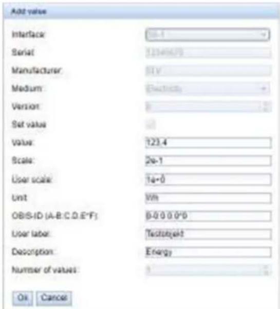
Figure 34 Creating the meter a pulse meter (sample data)
The parameters Value and Unit should be set to the values in the meter display. The unit may differ, we recommend using basic units such as Wh as opposed to the standard unit often used for energy meters kWh.
The parameter Scale indicates the pulse value. The value entered in Value is incremented by this value during a meter pulse. The calculation of the pulse value results from the indication on the meter, here are a few examples:
■ 1000 Imp/kWh → 0.001 = 1e-3 with unit kWh or 1 = 1e+0 with unit Wh
■ 5000 Imp/kWh → 0.0002 = 2e-4 for unit kWh or 0.2 = 2e-1 for unit Wh
■ 200 Imp/m³ → 0.5 = 5e-1 with unit m³
The parameters Value and Scale must be set to ensure correct metering, the other parameters are used for an easily readable data display. The user can refer to Table 26 and Table 27 for the fields Description and Unit. This ensures a uniform display across all meters.
The measured value set up in this way is now updated by incrementing, depending on the number of pulses acquired, with each readout. For S0 meters, only one meter value can be assigned.
7.2 Troubleshooting the pulse interface
7.2.1 The meter does not increment
Check the technical specification of the pulse generator, especially its internal resistance or its current consumption in active/inactive state. The detection threshold is approx. 8-10 mA.
Check the polarity.
If errors could not be rectified, please contact your local Danfoss support.
8 Reading meters via serial interface
One way to read meters is via serial communication. Physically, these can be found in the form of RS-485, RS-232, optical interface (D0) or current loop interface (C0).
Some SonoCollect devices offer an RS-485 interface or an RS-232 interface. Coupling of other physics requires appropriate converters (e.g. optical read head for RS-485).
In addition to the physics, the meter's protocol is crucial. Here you can find several variants:
■ EN 62056-21, also IEC 61107 or IEC 1107 (ASCII/protocol, called DLDE by us), part of DLMS
■ "Real" DLMS according to series of standards EN 62056
■ SML
Modbus RTU
The SonoCollect devices support both SML and EN 62056-21 (Mode A and Mode C). While SML is only processed as a receive stream (data push of the meter), EN 62056-21 allows both the data push to be processed and data to be actively requested from the meter (data request).
8.1 Setup of the interface in the web front end
The setup of a meter with serial interface is only possible manually.
First the serial interface must be activated and parameterized. This is done in the Configuration tab via the parameter set DLDE.... (see section 4.4).
8.1.1 Serial mode
The parameter Serial mode activates the serial interface and defines the basic range of functions:
■ Disabled
DLDE
- Transparent/TCP
■ Transparent/UDP
The Transparent modes allow the use of the physics of the serial interface via a TCP or UDP port. The data stream is thus forwarded from the serial interface to an IP interface (network (LAN) or mobile radio (WAN)). The device then operates in a similar way to an Ethernet-to-serial converter or even a mobile radio router with a serial interface. The network port to be used is defined in the parameterDLDE transparent port.
√ The transparent mode makes it possible to read meters via serial interface even if their protocol is not directly supported by the device. The protocol can then be processed in the host system while the device provides physical connectivity.
The mode DLDE activates the reading of meters by the device itself. This means that the protocol is handled directly in the device and the meter must be created accordingly (see section 8.2).
√ Regardless of the mode, the parameters for baud rate, bit representation and timeouts must be set to match the serial (see section 8.1.2).
8.1.2 DLDE baud rate, data bits, stop bits and parity
The parameters DLDE baud rate, DLDE data bits, DLDE stop bits and DLDE parity are used to configure the bit display on the serial interface.
The baud rate essentially determines the speed of the data transmission. The other parameters describe the byte display:
■ The number of data bits is either 7 bits or 8 bits.
- The parity activates an additional bit to enable error detection. While parity None (no parity, N) re-nounced this additional bit, the modes Even (even parity, E) or Odd (odd parity, O) add a corresponding bit which supplements the data bits in such a way as to obtain an even or odd number of ones (1) in the data stream. The modes Mark (character, M) and Space (space, S) complement either a 1 or a 0, but are practically not used.
■ The number of stop bits is either 1 bit or 2 bits.
Usual settings are exemplary:
■ 2400-8-E-1 (e.g. for M-Bus)
■ 300-7-E-1 (e.g. for meters according to EN 62056-21)
■ 9600-8-N-1 (e.g. for meters with SML push or according to DLMS)
8.1.3 DLDE mode
The protocol implementation of EN 62056-21 takes place in three variants. This is set by the parameter DLDE mode.
The mode Push is provided for meters that send their data cyclically, unsolicited. The meters according to EN 62056-21 and SML protocol can be processed.
Meters which have to be requested according to EN 62056-21 can be requested either via the modes Request or Request (C-Mode). Request is the mode A described in the standard. When the meter is queried, it gives its meter values in response. The mode C described in the standard allows a baud rate change before the response with meter data. For this purpose an additional telegram exchange is mandatory (baud rate negotiation). The exchange is supported in the Request (C-Mode) mode, but the set baud rate is requested.
8.1.4 DLDE timeouts
The serial interface uses three different timeouts with DLDE first timeout, DLDE idle timeout and DLDE full timeout (in transparent mode only the DLDE idle timeout).
The DLDE idle timeout specifies what time the serial interface must be "idle", i.e. no data is sent/received, in order to detect the end of a telegram (end of communication). It is mainly used for package formation of the serial data stream, i.e. the assignment of incoming data to a logical unit (data packet). In the Push mode this time is used to detect the start of the telegram, therefore no data may be sent from the meter for this time.
The DLDE first timeout specifies what time it takes to wait for a response from the meter. If no data is received within this time from the request, the readout attempt is aborted.
The DLDE full timeout indicates the latest time at which reception is interrupted in order to process the received meter data. This parameter also terminates reception if the DLDE idle timeout is not reached because data is continuously received (without idle time, e.g. in the event of faults).
8.2 Setup of the meter in the web front end
After activating and parameterizing the serial interface, the meter can be added in the Meter tab.
The meter is first created via the Add button or the context menu. To do this, the Interface must be set to DLDE in the dialog. The parameters Serial and Manufacturer are used to assign the meter data to the meter; their input is therefore mandatory. Further data Medium or User label are optional and can be assigned. The user may refer to Table 25 for the Medium field. This ensures a uniform display across all meters. Use the Ok button to accept the entries and the meter is created in the meter list in the Meter tab.
![Add metal Interface: DLDE Serial: 12345678 Manufacturer: SLV Medium: Electricity Version: 0 % Link: Encryption key: Cycle [s] 0 % User label: Testcoehler Number of meters: 1 % OK Cancel](/content/2026/05/849664/images/276437087ad982adaea20b6f041b2ea5ec6c8b2b2ac244f77c4e1b9234d07f58.jpg)
Figure 35 Creating a DLDE meter (sample data)
A meter value must now be added to the newly created meter. This is done by right-clicking on the newly added DLDE meter and selecting the Add value command from the context menu. This command opens a dialogue box for entering the parameters of the meter value.
Figure Creating the meter a DLDE meter (sample data)
![Add value Interface: 0.00E Serial: 12.545678 Manufacturer: 5.8 Medium: Electricity Version: 0 Set value: 0 Value: 0 Scale: 1e+3 User scale: 1e+0 Unit: [M] CBIS-ID (A-B,C,D,E,F): 1-0.1.8.0*255 User label: Minenergy Bezug Description: Energy Number of values: 1 OK Cancel](/content/2026/05/849664/images/b2871eed364960da67bf5b67f82063b58973a03ea27628232b5d5e4dd4ec87c1.jpg)
Figure 36 Creating the meter a DLDE meter (sample data)
The assignment of meter values for EN 62056-21 (DLDE) is based on OBIS codes. This 6-digit code is standardized worldwide and clearly describes the measured value. Therefore, it is mandatory to assign the correct value in the parameter OBIS-ID (A-B:C.D.E*F). The parameters Unit and Scale should also be set according to the meter.
We recommend the use of base units like Wh and a scaling factor Scale of 1e+3 compared to the oten used standard unit for energy meters kWh with factor 1e+0 .
The user can refer to Table 26 and Table 27 for the fields Description and Unit. This ensures a uniform display across all meters.
The measured value set up in this way is now read out and recorded cyclically by the meter. The DLDE meters often transmit multiple values for various OBIS codes, so additional meter values can be added to the meter. Here are a few examples of commonly used OBIS codes, especially for energy meters:
■ 1-0:1.8.0*255 → Total value of active energy import
■ 1-0:1.8.1*255 → Total value of active energy import (tariff 1)
■ 1-0:1.8.2*255 → Total value of active energy import (tariff 2)
■ 1-0:2.8.0*255 → Total value of active energy export
■ 1-0:3.8.0*255 → Total value of apparent energy import
■ 1-0:4.8.0*255 → Total value of apparent energy export
■ 1-0:1.7.0*255 → Instantaneous value of active power import
■ 1-0:31.7.0*255 → Instantaneous current phase 1
■ 1-0:51.7.0*255 → Instantaneous current phase 2
■ 1-0:71.7.0*255 → Instantaneous current phase 3
■ 1-0:32.7.0*255 → Instantaneous voltage phase 1
■ 1-0:52.7.0*255 → Instantaneous voltage phase 2
■ 1-0:72.7.0*255 → Instantaneous voltage phase 3
8.3 Troubleshooting the serial interface
8.3.1 Meters are not read out
Check whether the parameters of the serial interface are set correctly in the Configuration tab.
Check whether the meter supports the protocol according to IEC 62056-21 (DLDE mode Request) or spontaneously transmits data according to IEC 62056-21 or SML format (DLDE mode Push).
Check the timeout parameters of the serial interface in the Configuration tab.
Activate the raw data log with Raw data log in the Configuration tab. The communication process can be analyzed using this raw data log.
If errors could not be rectified, please contact your local Danfoss support.
9 Transmission of meter data
A basic distinction is made between actively sending data, the data push, and collecting data, the data pull when transmitting meter data to third-party systems such as meter data management, energy management or monitoring systems.
The SonoCollect device is the client and the third-party system is the server in the client-server model. In the case of the data pull, the SonoCollect device is the server and the third-party system is the client. The client establishes the connection and monitors the data exchange. The server answers the requests and executes the commands of the client.
This chapter describes the data push, which can be configured in the data concentrators in the Report tab. The data pull is described separately, e.g. in the chapter 11 or in the section 2.6.
9.1 Instances and database
In the SonoCollect devices of 10 independent report instances can be parameterized. The settings such as cycle time, data format, transport mechanism and other parameters can be set for each of these reports in the Server tab (see section 2.6).
The data sent in the reports is stored in a database. The database is file-based and uses SQLite. The report instances therefore have the same data.
The database is not active until at least one report instance is active. If not, no data is stored in the database and is therefore not available later.
Only active values (column Active in the Meter) tab are written to the database. Other values are not available later.
9.2 General settings
Each instance has a parameter set. This can be configured via the web interface in the Report tab. Some parameters are always to be configured, others depend on the set mode.
The following parameters are available and to be configured for each instance:
■ Report mode: Operating mode or deactivation of the respective instance (see also section 4.6)
■ Report format: Data format for the transmission of the respective instance (see also section 4.6)
- Report cycle mode: Format specifying the transmission cycle of the respective instance (see also section 4.6).
■ Report cycle: Transmission cycle of the respective instance (see also section 4.6)
■ Report cycle date (local): Day of transmission of the respective instance, for weekly to annual format (see also section 4.6)
- Report cycle time (local): Time of transmission of the respective instance, with daily to annual format specification (see also section 4.6)
9.3 Preset data or file formats
The SonoCollect devices have some predefined data formats.
9.3.1 XML format
Several XML formats are available for transmission. XML is a data stream distinguished by so-called tags (entries and attributes) for the display of hierarchically structured data. These data are usually in plain text and therefore readable by both humans and machines.
The XML format is specified as follows:
| Entry | Attribute | Description |
| interface | Contains a complete package with one or more muc entries. | |
| MESSAGE_TYPE | Specifies the type/version of the package: e. g. 1 | |
| muc | Contains the data for one device at a time with corresponding meter entries. | |
| MUC_ID | Hexadecimal notation of the serial number of the device (corresponds to the serial number/MAC address on the website in the General tab). | |
| VERSION | Protocol version | |
| TIMESTAMP | UNIX time (UTC) at time of transmission | |
| meter | Includes one or more data entries for a meter | |
| INTERFACE | Interface of the meter, as number or as text | |
| 1: S0 | ||
| 2: M-Bus | ||
| 5: wM-Bus | ||
| 6: DLDERS | ||
| 10: System | ||
| METER_ID | Serial number of the meter | |
| USER | Application-specific description of the meter (configured in the Meter tab) | |
| MAN | Manufacturer code of the meter | |
| VER | Version number of the meter | |
| MED | Medium of the meter, see second column in Table 25 | |
| MED_ID | Medium ID of the meter, see first column in Table 25 | |
| data | Contains one or more measured values of a type in the respective entry entries, which are specified via the attributes. | |
| OBIS_ID | OBIS code according to OBIS specification is configured via the web page, in version XML-8 the DIF/DIFE/VIF/VIFE fields from the M-Bus/wM meter value are transmitted in this code. | |
| DESCRIPTION | See second column in Table 26 | |
| MEDIUM | Medium of the meter, see second column in Table 25 | |
| UNIT | See second column in Table 27, energy values in Wh are converted to kWh | |
| SCALE | Signed scaling factor (scientific notation) | |
| DIF | DIF/DIFE fields from the M-Bus/wM-Bus raw data, the display is in hexadecimal byte notation. | |
| VIF | VIF/VIFE fields from the M-Bus/wM-Bus raw data, the representation is in hexadecimal byte notation. | |
| USER | Application-specific description of the meter value (configured in the Meter tab) | |
| entry | Data entry consisting of a time stamp (T) and a measured value (VAL) | |
| parameter | Contains a parameter value | |
| NAME= "T" | The associated parameter value represents the UNIX time (UTC) at the time of the measurement, if transmitted by the meter with the measured value. | |
| NAME= "T_MUC" | The associated parameter value represents the UNIX time (UTC) of the device at the time of receipt of the measurement data | |
| NAME= "VAL" | The associated parameter value represents the measured value specified in data. |
Table 18: Format of the XML data
The following table illustrates the different protocol versions:
| Entry | Attribute | XML-3 | XML-6 | XML-7 | XML-8 | XML-9 |
| interface | x | x | x | x | x | |
| MESSAGE_TYPE | x | x | x | x | x | |
| muc | x | x | x | x | x | |
| MUC_ID | x | x | x | x | x | |
| VERSION | 1F4 | 1F7 | 1F8 | 1F9 | 9 | |
| TIMESTAMP | x | x | x | x | x | |
| meter | x | x | x | x | x | |
| INTERFACE | Numeric | Numeric | Numeric | Numeric | Text | |
| METER_ID | x | x | x | x | x | |
| USER | x | x | x | x | ||
| MAN | x | x | x | |||
| VER | x | x | x | |||
| MED | x | x | x | |||
| MED_ID | x | |||||
| data | x | x | x | x | x | |
| OBIS_ID | x | x | x | Raw data | x | |
| DESCRIPTION | x | x | x | x | x | |
| MEDIUM | x | x | x | x | ||
| UNIT x x x x x | ||||||
| SCALE | x | x | x | x | x | |
| VIF | x | |||||
| DIF | x | |||||
| USER | x | x | x | x | ||
| entry | x | x | x | x | x | |
| parameter | x | x | x | x | x | |
| NAME= „T“ | x | x | x | x | x | |
| NAME= „T_MUC“ | x | x | x | x | x | |
| NAME= "VAL" | x | x | x | x | x |
Table 19: Data in different XML versions
A sample XML package after version 3 looks like this:
<?xml version="1.0" encoding="utf-8"?>
<interface MESSAGE_TYPE="1">
<muc MUC_ID="13fd0" VERSION="1F4" TIMESTAMP="1252004322">
<meter METER_ID="92752244" INTERFACE="5">
<data DESCRIPTION="VOLUME" UNIT="m^3" SCALE="0.001" MEDIUM="WATER"
OBIS_ID="8-0:1.0.0*255">
<entry>
<parameter NAME="T">1253000282</parameter>
<parameter NAME="T_MUC">1253000282</parameter>
<parameter NAME="VAL">2850427</parameter>
</entry>
<entry>
<parameter NAME="T">1253000482</parameter>
<parameter NAME="T_MUC">1253000482</parameter>
<parameter NAME="VAL">2850428</parameter>
</entry>
</data>
<data ...>
...
</data>
</meter>
<meter ...>
...
</meter>
</muc>
</interface>
9.3.2 CSV format
Several CSV formats are available. CSV is a table-like file format which uses a character, at Danfoss a semicolon (;" to separate numerical values and texts (columns) from each other. This makes processing or viewing e.g. with Excel very easy.
The header line in the file specifies the column heading; the following lines contain data on the meter and the meter values at a particular readout time.
The CSV data have the following format:
| Column name in header | Description |
| Information about the meter | |
| Index Indexes the different devices within a CSV file | |
| Timestamp | Unix time stamp (UTC) or readable time information of the device at the time of readout |
| DeviceId | ID of the meter, composed of manufacturer ID, serial number, version number and media type |
| Link | Primary address of the meter or RSSI for wM-Bus meters |
| User | Application-specific description of the meter (column User label in Meter tab) |
| IndexX | Indexes the different meter values of a meter |
| ValueX | Meter value (transmitted by the meter) |
| ScaleX | Scaling factor in scientific notation (transmitted by the meter) |
| UnitX | Unit, see second column in Table 27 (transmitted by the meter) |
| DescriptionX | Description, see second column in Table 27 (transmitted by the meter) |
| UserX | Application-specific description of the meter value (column User label in Meter tab) |
| TimestampX | The timestamp transmitted by the meter (Unix timestamp or readable time), or 0 if not available. |
| ObisidX | OBIS-ID (column OBIS-ID in Meter tab) |
Table 20: CSV format
The first columns of a line entry contain data of the meter, including the meter identification (address) and the time the data was read out. The other columns are inserted dynamically according to the configured meters and number of meter values, whereby the meter values are inserted starting from 0 (e.g.: Value0).
The following table illustrates the different protocol versions:
| Column | CSV-0 | CSV-1 | CSV-3 | CSV-4 | CSV-5 | CSV-6 | CSV-9 |
| Index | x | x | |||||
| Timestamp | Unix | Unix | Unix | Unix | Unix | Unix | Plain text |
| DeviceId x x x | x x x x | ||||||
| Link | x | x | x | x | |||
| User | x | x | x | ||||
| IndexX | x | x | |||||
| ValueX | x | x | x | x | x | x | x^* |
| ScaleX | x | x | x | x | x | x | |
| UnitX | x | x | x | x | x | x | x |
| DescriptionX | x | x | x | x | x | x | x |
| UserX | x | x | x | x | x | x | |
| TimestampX | Unix | Unix | Unix | Unix | Unix | Plain text | |
| ObisIdX | x | x | x | x | x | x | x |
*scaled value
Table 21: Data in different CSV versions
An example record of the CSV data in version 3 is shown in the following figure:
| A | B | C | D | E | F | G | H | I | J | K | L | M | |
| 1 | Timestamp | Device0 | Value0 | Scale0 | Unit0 | Description0 | User0 | Timestamp0 | Obisid0 | Value1 | Scale1 | Unit1 | Description1U |
| 2 | 1370135021 | EMU-000238 | 987 | 1,00E+00 Wh | Energy | 0 | |||||||
| 3 | 1370135025 | EMH-003898 | 18354 | 1,00E+00 h | On Time | 1339357800 | 24214 | 1,00E+01 Wh | Energy | ||||
| 4 | 1370135028 | ZRM-314040 | 90 | 1,00E-03 m^3 | Volume | label5 | 1369836720 | 1943 | 1,00E-02 Grad C | Flow Tempe k | |||
| 5 | 1370135030 | LUG-6666020 | 436 | 1,00E+01 Wh | Energy | label 1 | 1370141940 1-0:0.0.0*0 | 650 | 1,00E-03 m^3/h | Volume Flow k | |||
| 6 | 1370135031 | 245 | 1,00E-03 m² | 0 0-2:2.0.0*0 | |||||||||
| 7 | 1370200016 | EMU-000238 | 987 | 1,00E+00 Wh | Energy | 0 | |||||||
| 8 | 1370200020 | EMH-003898' | 18373 | 1,00E+00 h | On Time | 1339422780 | 24228 | 1,00E+01 Wh | Energy | ||||
| 9 | 1370200022 | ZRM-314040 | 90 | 1,00E-03 m^3 | Volume | label5 | 1369901700 | 1945 | 1,00E-02 Grad C | Flow Tempe k | |||
| 10 | 1370200025 | LUG-6666020 | 436 | 1,00E+01 Wh | Energy | label 1 | 1370206920 1-0:0.0.0*0 | 650 | 1,00E-03 m^3/h | Volume Flow k | |||
| 11 | 1370200026 | 245 | 1,00E-03 m² | 0 O - 2 : 2.0.^ * O^ * | |||||||||
| 12 | |||||||||||||
Figure 37 Section of a CSV log file
9.3.3 JSON format
A JSON format is available for transmission. JSON is a compact, serialized data stream for representing structured data. These data are usually readable by both humans and machines and separated by separators.
| Object | Property | Data type | Description |
| muc | Object | Contains the data for one device at a time with corresponding meter entries. | |
| MUC_ID | String | Hexadecimal notation of the serial number of the device (corresponds to the serial number/MAC address on the website in the General tab). | |
| VERSION | String | Protocol version | |
| TIMESTAMP | Integer | UNIX time (UTC) at time of transmission | |
| meter | Array | Array of meter objects | |
| meter | Object | Contains the data for one meter at a time with corresponding data entries. | |
| METER_ID | String | Serial number of the meter | |
| INTERFACE | String | Interface of the meter | |
| S0 | |||
| MBus | |||
| wMBus | |||
| DLDERS | |||
| System | |||
| MAN | String | Manufacturer code of the meter | |
| VER | String | Version number of the meter | |
| MED | String | Medium of the meter, see second column in Table 25 | |
| MED_ID | String | Medium ID of the meter, see first column in Table 25 | |
| USER | String | Application-specific description of the meter (configured in the Meter tab) | |
| data | Array | Array of data objects | |
| data | Object | Contains the data for one meter value each with corresponding entry entries. | |
| DESCRIPTION | String | See second column in Table 26 | |
| UNIT | String | See second column in Table 27; Energy values in Wh are converted to kWh | |
| SCALE | String | Signed scaling factor (scientific notation) | |
| OBIS_ID | String | OBIS code according to OBIS specification is configured via the web page, in version XML-8 the DIF/DIFE/VIF/VIFE fields from the M-Bus/wM-Bus raw data are transmitted to the meter value in this code. | |
| USER | String | Application-specific description of the meter value (configured in the Meter tab) | |
| DIF | String | DIF/DIFE fields from the M-Bus/wM-Bus raw data, the display is in hexadecimal byte notation. | |
| VIF | String | VIF/VIFE fields from the M-Bus/wM-Bus raw data, the representation is in hexadecimal byte notation. | |
| entry | Array | Array of data objects | |
| entry | Object | Data entry consisting of a time stamp (T) and a measured value (VAL) | |
| T_MUC | Integer | UNIX time (UTC) of the device at the time of receipt of the measurement data | |
| T | Integer | UNIX time (UTC) at the time of the measurement, if transmitted by the meter with the measured value | |
| VAL | String | Measured value specified in data |
Table 22: Format of the JSON data
A sample JSON packet looks like this (breaks inserted due to display):
{"muc":{"MUC_ID":"6891d0800e62","VERSION":"1","TIMESTAMP":1601297784,"meter":[
{"METER_ID":"00000001","INTERFACE":"MBus","MAN":"SIE","VER":21,"MED":"Electricity",
"MED_ID":2,"USER":"metering1","data":[
{"DESCRIPTION":"Energy","UNIT":"kWh","SCALE":0.001,"OBIS_ID":"1-0:1.8.0*255",
{"T_MUC":1601297765,"VAL":"537980",{"T_MUC":1601297770,"VAL":"537980"}],
{"METER_ID":"00094824","INTERFACE":"MBus","MAN":"BEC","VER":32,"MED":"Electricity",
"MED_ID":2,"data":[
{"DESCRIPTION":"Energy","UNIT":"kWh","SCALE":0.01,"DIF":"0E","VIF":"84 00","entry":[
{"T_MUC":1601297679,"VAL":"2887897", {"T_MUC":1601297761,"VAL":"2887897",
{"T_MUC":1601297765,"VAL":"2887897", {"T_MUC":1601297770,"VAL":"2887897"],
{"DESCRIPTION":"Power","UNIT":"W","SCALE":0.01,"DIF":"04","VIF":"A9 00","entry":[
{"T_MUC":1601297679,"VAL":"382207", {"T_MUC":1601297761,"VAL":"382207",
{"T_MUC":1601297765,"VAL":"382207",{"T_MUC":1601297770,"VAL":"382207"}]]
9.3.4 User format
If the above options do not fit or are not sufficient, the report can be switched to scripting with Report format User.
This provides the user with an XSLT parser to generate specific data formats. An overview of this can be found in section 10.7 and specifically in section 10.7.1.
Only one user format is available for the standard operating modes (e.g. TCP or FTP). For different, user-specific formats, the script-based report (see section 9.10) must be used.
9.4 Data transmission via TCP
A common communication method for transmitting data is to use the data content of TCP packets. The data is thus sent as a data stream to the remote station, where it is collected and processed.
The data is transmitted unencrypted using TCP. If encryption is necessary, the data should be sent via TLS (see section 9.5).
Since the data processing systems are usually databases or similar, an automated processable data format such as XML or JSON is preferred here. But any data format can be transferred.
According to the destination the parameters Report address, Report port and Report directory have to be set. An empty path specification in Report directory generates a TCP data stream, a set path specification generates an HTTP data stream (e.g. "/", "/upload").
Configuration of server connection
| Report instance: | 2 - TCP - 192.168.2.228 |
| Report mode: | TCP |
| Report format: | XML-9 |
| Report cycle mode: | Minute |
| Report cycle: | 15 |
| Report cycle date (local): | 01.01.2020 |
| Report cycle time (local): | 00:00 |
| Report address: | 192.168.2.228 |
| Report port: | 8 086 |
| Report directory: | |
| Report username: | |
| Report password: | |
| Report source address: | |
| Report destination address: | |
| Report user parameter 1: | |
| Report user parameter 2: | |
| Report user parameter 3: |
Figure 38 Example configuration for 15-minute transmission of XML data via TCP
9.5 Data transmission via TLS
As a rule, an unencrypted TCP connection for the transmission of data (see section 9.4) is not recommended in productive use. Encryption is common here.
The data stream is asymmetrically encrypted via TCP by using TLS. Each participant has both a private key known only to him and a public key known to everyone. Data that is exchanged is encrypted with the public key of the other participant. The decryption is then performed using the secret private key on the recipient side.
Configuration of server connection
| Report instance: | 1 - TLS - https://192.168.2.228 |
| Report mode: | TLS |
| Report format: | XML-8 |
| Report cycle mode: | Hour |
| Report cycle: | 1 |
| Report cycle date (local): | 01.01.2020 |
| Report cycle time (local): | 00.00 |
| Report address: | https://192.168.2.228 |
| Report port: | 443 |
| Report directory: | /upload.php |
| Report username: | |
| Report password: | |
| Report source address: | |
| Report destination address: | |
| Report user parameter 1: | |
| Report user parameter 2: | |
| Report user parameter 3: |
Figure 39Example configuration for hourly transmission of XML data via TCP
TLS also offers mutual authenticity checks of client and server by means of signed certificates, which provides a very high level of security. A distinction is made between server-side authentication and client-side authentication, depending on which side is authenticating. Both variants are supported, also in combination, by the products of Danfoss.
√ The SonoCollect devices use certificates in the PEMformat (RFC 7468).
In the case of server-side authentication, the server, and in the case of data collectors and gateways therefore the remote terminal, must authenticate itself. In order to check its certificate, a certificate from a certification authority (its public key) must be installed on the SonoCollect device against which the server certificate can be checked.
Unless otherwise specified and available, the file app/cacert.pem is used to check the authenticity of the server on the SonoCollect devices (RFC 4945).
The client, and therefore the device in the case of data collectors and gateways, must authenticate itself with client-side authentication. It requires an issued certificate and a secret private key in this case.
Unless otherwise specified and available, the file app/clicert.pem is used as the certificate of the device for the SonoCollect devices (RFC 5280).
Unless otherwise specified and available, the file app/clikey.pem is used as the private key of the device for the SonoCollect devices (RFC 5958).
The certificates can be uploaded manually via SFTP (see also section 3.4). However, it is also possible to import via the Service tab (see section 4.10). The file(s) must be packed as a *.tar.gz file in this case.
To create a *.tar.gzarchive, the free, open source software 7zip can be used. The file meter_conf_import.csv can be packed herewith without subdirectory first into a *.tar ball and afterwards into a *.gz archive.
If the files are to be named differently or different certificates are possibly required per configured server instance, the use of other file names and paths must be entered manually in the file app/chip.ini (see also section 10.3).
The following parameters are entered for the assignment to the respective report in the file app/chip.ini in the area [REPORT_x]:
CA_FILE: the public key of the certification authority matching the server certificate, e.g.:
CA_FILE=app/srv\instance1.pem
CERT_FILE: the certificate of the device for the respective report, e.g.: CERT_FILE=app/dcu.pem
KEY_FILE: the private key matching the certificate of the device, e.g.: KEY_FILE=app/key.pem
9.6 Sending files via FTP
Another common communication method for transferring data is the use of the FTP protocol, especially when it comes to file-based transfer.
The data is transmitted unencrypted using FTP. If encryption is required, data should be sent via SFTP or FTPS (see section 9.6.1).
Since files are transferred, the CSV format is preferred here. It enables easy import into Excel or databases among other things. However, other data formats can also be transferred.
According to the destination, the parameters Report address, Report port, Report directory, Report username and Report password must be set.
Configuration of server connection
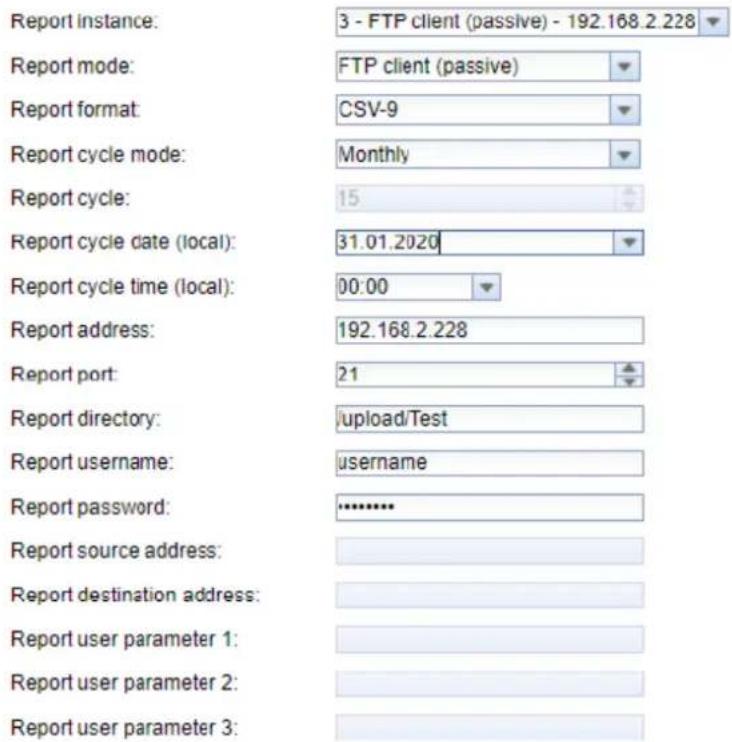
Figure 40Example configuration for automatic transfer of CSV data via FTP
The Report mode is either FTP (active) or FTP (passive). Both differ in the procedure by the definition of the port to be used for the data connection. FTP uses one TCP port for the control connection, e.g. for transmitting control commands, and a second TCP port for the data connection. The client specifies the second port; in the passivemode, the server specifies the second port in the active mode. Therefore, FTP (passive) is usually used, because firewalls on the server side often only allow outgoing communication on an "arbitrary" port.
√ If no Report port is specified, the default port 21 is used.
9.6.1 Sending files via SFTP or FTPS
As a rule, an unencrypted FTP connection for transferring files (see section 9.6) is not recommended for productive use. Encryption is common here.
By using TLS, secure transmission is also possible for FTP (see also section 9.5). A distinction is made here between SFTP, an FTP imitated via SSH, and FTPS, FTP via a channel secured by TLS. Since SSH also uses
SSL, both are very similar from a security standpoint. SFTP has the advantage that SSH and therefore only one port is used (usually port 22) while FTPS uses the two ports as with FTP, only the data content is encrypted.
√ Encrypted/secured FTP is usually SFTP not FTPS.
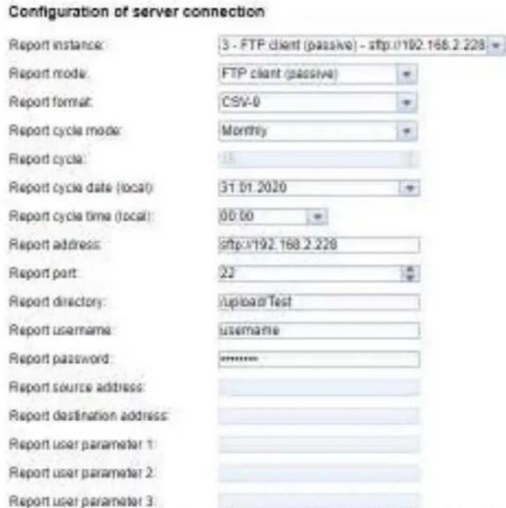
Figure 41 Example configuration for monthly transfer of CSV files via SFTP
Since both variants involve a connection secured by TLS, appropriate certificates must be stored and configured. Background information and the procedure are described in section 9.5.
9.7 Sending e-mails via SMTP
Data can also be sent by e-mail. SMTP is used for this purpose.
It is necessary to send this data in the text of the e-mail or as an attachment depending on the requirement.
SMTP itself is not encrypted. The STARTTLS extension provides a certain level of security based on TLS, but the connection is also established unencrypted. For complete encryption of the communication, the use of SMTPS is recommended.
Todo.
9.7.1 Report as content of the e-mail
Todo.
9.7.2 Report as attachment to an e-mail
Todo.
9.7.3 SMTP with STARTLS
Todo.
9.8 Data transmission via MQTT
MQTT is a widely used standard in cloud communications, specifically for sending data to a cloud system. It is an open network protocol which can be used in the area of M2M communication despite potentially high delays and networks which are not continuously available. TCP ports 1883 and 8883 reserved for MQTT, the latter for encrypted communication using the TLS protocol.
MQTT distinguishes between:
■ Publisher: Device or service that sends the data, e.g. a sensor or a data concentrator.
- Subscriber: Device or service that processes the data, e.g. a visualization or a billing software.
■ Broker: Central data hub for MQTT, this also manages the network and ensures robustness
MQTT uses so-called topics to classify messages hierarchically. This is comparable to a path specification. The publisher sends data of these Topics to the Broker. This then distributes the data to the subscribers.
Certificates must be provided on the device for the encrypted connection via port 8883. Ask your administrator in this case.
Example Azure Cloud
Set the parameters as follows to connect to an Azure cloud:
■ Report address: Internet address of the Azure cloud server
■ Report directory: Device ID and Topic for the Azure Cloud
- Report user name: User name for the Azure cloud, usually consisting of internet address, device name and API version.
- Report password: Password for the Azure cloud, usually a composition of access key, signature and expiration date.
The following example should clarify the parameters:
Report address: ExampleHub.azure-devices.net
Report directory: devices/MUC063C/messages/events
Report user name: ExampleHub.azure-devices.net/MUC063C/?api-version=2018-06-30
Report password: SharedAccessSignature sr=ExampleHub.azure-devices.net%2fdevices%2f
MUC063C&sig=rQXaVuN%2bjWqh0vVr9E6ybo7VbMBQ4QQNOidzMtoql2g%3d&se=1639260907
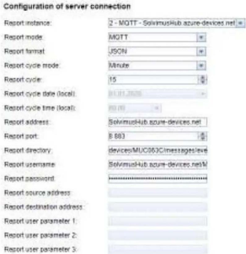
Figure 42Example configuration for Azure Cloud
9.8.2 Example AWS Cloud
Set the parameters as follows to connect to an AWS cloud:
■ Report address: Internet address of the AWS cloud server
■ Report directory: User name and Topic for the AWS Cloud
■ Report user name: User name for the AWS Cloud
■ Report password: Password for the AWS Cloud
The following example should clarify the parameters:
■ Report address: b-fbf31b71-1234-5678-a052-3b5a4fafabcd-1.mq.eu-central-1.amazonaws.com
■ Report directory: demo201909/testing
■ Report user name: demo201909
■ Report password: YXcajMTbZ7WUBzrsst
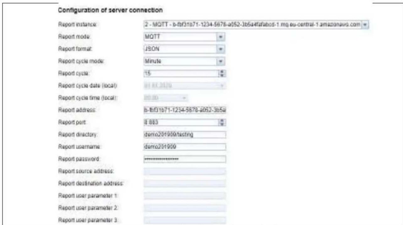
Figure 43Example configuration for AWS Cloud
9.9 Local file storage
The meter data can also be stored directly on the device as a file. This can be used if the data is to be called via FTP, for example. This is called a data pull.
As with all other reports, the predefined formats and the user-specific format are available for selection.
The files are stored according to the set parameters in the folder ext/Log/YYYY/MM, where YYYY is the associated year and MM is the associated month for the report (according to the system time of the device).
The following settings, for example, cause a CSV file containing all readings from the previous report period to be created and stored on the system every day at 01:00 local time:
Configuration of server connection
| Report instance: | 1 - File |
| Report mode: | File |
| Report format: | CSV-9 |
| Report cycle mode: | Daily |
| Report cycle: | 15 |
| Report cycle date (local): | 01.01.2020 |
| Report cycle time (local): | 01:00 |
| Report address: | |
| Report port: | 0 |
| Report directory: | |
| Report username: | |
| Report password: | |
| Report source address: | |
| Report destination address: | |
| Report user parameter 1: | |
| Report user parameter 2: | |
| Report user parameter 3: |
Figure 44Example of a report via local file storage
9.10 Script-based report
If the above options do not fit or are not sufficient, the report can be switched to scripting using Report port User.
This way, the user has free access to the powerful Linux tools supplied with the device. Each instance is assigned its own script. An overview of this can be found in section 10.7 and specifically with examples in section 10.7.2.
Since the script-based report offers a lot of freedom, additional parameters Report user parameter 1, Report user parameter 2 and Report user parameter 3 are available to the instance, in which any texts can be entered. This information is then available to the script. The parameters of the report instance can be used in the script, but do not have to be.
Configuration of server connection
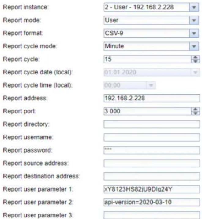
Figure 45Example configuration for 15-minute transfer of CSV data via a user script
9.11 Specific troubleshooting
Troubleshooting the transmission of meter data is very complex. Typically it is due to connectivity or authentication/encryption. Indications of the cause of the error can be found in the Logtab.
Check whether the remote terminal can be reached. Use the ping command from the SSH console of the device for this purpose (see also section 10.1.2). This will also check the name resolution (DNS). A hostname should be converted to an IP address when pinging.
Check whether a firewall blocks the data exchange or the routing is configured accordingly. Ask your administrator in this case.
In the case of TLS encryption, check whether all necessary certificates are available, especially the CA certificate for the remote terminal.
Check the correct entry of Report username and Report password as well as Report address, Report port and Report directory of the respective instance.
If errors could not be rectified, please contact your local Danfoss support.
10 Advanced configuration options
10.1 Linux operating system
The SonoCollect devices are based on the Linux operating system. This ensures that the devices continuously follow the state of the art and that errors in the software are quickly found and corrected due to a large community. It also ensures a certain basic functionality and security for the user.
The Linux operating system is built through the Yocto/openembedded build environment, with all components included according to the latest version and security patches. The Linux itself is unchanged except for a few specific tools and customizations (e.g. solcmd). Corresponding Linux documentation can thus be used directly. For custom projects, additional components provided on the Yocto/openembedded platform can be made available on the target system.
10.1.1 User rights
Linux supports and has in principle user roles. There is operating system internally the user root with full access to all operating system functions. In addition, further users with restricted access can be created. Their permissions can be set by groups and names, mostly file access permissions (read, write or execute).
In case of the SonoCollect devices, in addition to the user root, the user admin has also been created. It has read and write access to the partitions /app and /ext and can execute files there. For the user, admin is the user who can completely configure the device.
√ The user web is created as the default user for the web interface, but has no access rights to the file system.
√ For reasons of downward compatibility, the user ftp is created as the default user for FTP access to the directory /ext.
The user root has no external access to the device. It protects the safety of the user. Only the user admin can grant the user root the release.
The password of the user root is generated randomly and device-specific during production and stored access-protected in a database.
10.1.2 Command line
The Linux operating system on the SonoCollect devices has a command line based on BASH. It allows the user and also other applications to execute commands via the command line.
The user can access the command line via an SSH console. The Netdiscover tool (see chapter 3) opens an SSH console with a Putty client.
10.1.3 Standard commands
The Linux operating system and the command line BASH provide certain built-in standard commands. Examples include:
■ help: Display list of all integrated commands
■ cd: Navigation in the directory tree
■ /s: List directory contents
■ cat: View file contents
■ cp: Copying files/directories
■ mv: Move/rename files/directories
■ rm: Delete files/directories
■ sync: Write the data from the RAM buffer to the data carrier
- chmod: Adjust access rights
■ grep: Search for text content
- echo: Output text
■ date: Display system time
■ ps: Show list of all running processes
■ tail: Output last lines of a file
■ netstat: Query the status of the network interfaces
■ ping: Network connectivity test
■ nslookup: Display of the DNS configuration
■ /sbin/ifconfig: Overview of the network interfaces
Further commands are provided by programs:
■ tcpdump: Recording network traffic
- openssl: Use of encryption, certificates and PKI
■ curl: Calling a server connection
■ esmtp: Sending e-mails
■ socat: Connecting two interfaces
vi: Editing files
■ xsltproc: Execution of XSL transformations
Solcmd command interpreter
For special application functions of Danfoss there is a command interpreter solcmd due to the system access rights. The interpreter can be called with various parameters and thus provides access to the application and its control.
The following parameters are supported:
■ format-partition-app: Formatting the configuration partition /app
■ format-partition-ext: Format the logging partition /ext
- config-partitions: Resetting the access rights to the partitions
- config-users: Transfer of the changed user settings
- config-hostname: Acceptance of the changed device name
- config-timezone: Adopting the time zone setting
■ restart-eth0: Restart of the Ethernet interface
■ restart-wifi: Restarting the WLAN interface (only if WLAN is available)
■ filter-vlan: VLAN filter for network interface (only if switch integrated)
■ start-ppp0: Establishing the PPP dial-up connection (mobile network)
■ stop-ppp0: Disconnection of the PPP dial-up connection (mobile network)
■ start-vpn: Establishing a VPN connection (OpenVPN)
■ stop-vpn: Terminating a VPN connection (OpenVPN)
- manual-vpn: Establishment of a VPN connection (OpenVPN) in the foreground with manual password entry
■ restart-server: Restarting the server services
■ regenerate-server-keys: Re-creating the keys for secured server services
■ start-solapp: Starting the main application
■ stop-solapp: Exit the main application
■ start-transparent-tty: Activate transparent data forwarding of a serial interface to Ethernet port
- stop-transparent-tty: Stop transparent data forwarding of a serial interface to Ethernet port
■ start-virtual-tty: Activating a virtual interface via an Ethernet port
■ stop-virtual-tty: Terminating a virtual interface via an Ethernet port
■ update-rtc: Writing the system time to the buffered real-time clock
■ factory-reset: Resetting the device to factory settings
■ update-system: Performing a System Update
■ reboot-system: Restarting the system
■ help: Command overview with explanation and examples
10.2 Update
The firmware can be updated manually or conveniently via the web interface (see section 4.10).
Access via SSH is necessary for a manual update, and the easiest way to download the update file is via SFTP. The tools for this are provided by the Netdiscover tool (see chapter 3).
First, the appropriate and signed update file *.enc must be loaded via SFTP into the directory ext/Upd (see section 3.4). It requires the admin access.
After uploading the file, the user must log in as admin via SSH (see section 3.5). In the command line (see section 10.1.2), the command solcmd update-system must then be executed. After completion, a reboot is necessary, which is triggered with the command solcmd reboot-system.
10.3 Configuration file chip.ini
The file /app/chip.ini contains the general system parameters and is therefore the central configuration file. The parameters are grouped into different sections. If the parameters are not configured in chip.ini, the default values are used.
In order for manual changes to the file chip.ini to be adopted by the device, it must be restarted via the web front end using the button Reboot system in the Service tab or the command line.
Manually changed data will only be permanently stored on the flash after a few minutes. As a result, such changes may not be applied after a power supply reset.
√ The file chip.ini can be transferred to another device via FTPS, taking into account the network configuration (e.g. different IP address).
| Parameter | Description | Value range | Standard |
| Group [IP] | |||
| ADDRESS | IP address of the device | 0.0.0.0-255.255.255.255 | 192.168.1.101 (explicit) |
| NETMASK | Subnet mask of the device | 0.0.0.0-255.255.255.255 | 255.255.255.0 (explicit) |
| GATEWAY | IP address of the gateway | 0.0.0.0-255.255.255.255 | 192.168.1.254 (explicit) |
| DHCP | Activation of the DHCP client | 0.1 | 0 (explicit) |
| DHCP_HOSTNAME | Host name for logging on to the DHCP server | Text, max. 255 characters, %SERIAL%: MAC address of the device | Device name from group [DEVICE] |
| Group [DEVICE] | |||
| NAME | Name of the device in the Tool Netdiscover | Text, max. 50 characters | Product name (explicit) |
| TIMEZONE | Time zone of the device | Text, max. 255 characters | Universal, corresponds to GMT |
| Group [DNS] | |||
| NAME_SERVER1 | IP address of the primary DNS server, IP or host name | Text, max. 255 characters | Not set |
| NAME_SERVER2 | IP address of the secondary DNS server, IP or host name | Text, max. 255 characters | Not set |
| Group [VPN] | |||
| ENABLE | Activation of the OpenVPN client | 0.1 | 0 |
| Group [WEB] | |||
| HTTP_ENABLE | Activation of the HTTP server | 0.1 | 1 |
| HTTPS_ENABLE | Activation of the HTTPS server | 0.1 | 1 |
| Group [FTP] | |||
| ENABLE | Activation of the FTP server | 0.1 | 1 |
| Group [SSH] | |||
| ENABLE | Activation of the SSH server | 0.1 | 1 |
| Group [UDPCFG] | |||
| ENABLE | Activation of the UDP-based search and configuration protocol | 0.1 | 1 |
| IPCFG_PASSWORD Password for changing the IP address via the UDP configuration protocol | Text, max. 255 characters Not set | ||
| Group [Danfoss] | |||
| BACNET_BBMD | IP of the BACnet BBMD (BACnet Broadcast Management Device) | Text, max. 255 characters | Not set |
| BACNET_BROADCAST | BACnet broadcast IP address (system configuration is used if not set) | Text, max. 255 characters | Not set |
| BACNET_CONFIGURE\NETWORK | Activation of a BACnet-specific network configuration (additional IP address) | 0, 1 | 0 |
| BACNET_DEVICEID | BACnet device ID | 1-4294967295 | 1 |
| BACNET_DEVICENAME | BACnet device name | Text, max. 255 characters | Not set |
| BACNET_ENABLE | Activation of BACnet communication | 0, 1 | 0 |
| BACNET_IP | BACnet IP (system configuration is used if not set) | Text, max. 255 characters | Not set |
| BACNET_LOCATION | BACnet site information | Text, max. 255 characters | metering |
| BACNET_NETMASK | BACnet network mask (system configuration is used if not set) | Text, max. 255 characters | Not set |
| BACNET_PORT | BACnet network port | 0-65535 | 47808 |
| DLDERS_ADDRESS\DISABLE | DLDE request with meter serial number (=0) or by means of wildcard request (=1), in this case only 1 meter may be connected. | 0, 1 | 0 |
| DLDERS_BAUDRATE | Baud rate for serial DLDE communication | 300, 600, 1200, 1800, 2400, 4800, 9600, 19200, 38400, 57600, 115200, 230400, 460800 | 9600 |
| DLDERS_DATABITS | Data bits for serial DLDE communication | 7, 8 | 7 |
| DLDERS_DEVPATH | Linux path for the serial DLDE interface | Text, max. 255 characters | Not set |
| DLDERS_ENABLE | Activation of the serial DLDE interface | 0, 1 | 0 |
| DLDERS_FIRST\TIMEOUT | Waiting time until first data is received from the meter. Push mode: Time without data reception (Wait idle, in ms) | 0-65535 | 3000 |
| DLDERS_FLOWCONTROL | Flow control for serial DLDE communication: 0: none, 1: XON/XOFF during transmission, 2: RTS/CTS, 8: XON/XOFF when receiving, 9: XON/XOFF during transmission and reception | 0, 1, 2, 8, 9 | 0 |
| DLDERS_FULL\TIMEOUT | Maximum waiting time for reading out the meter (in ms) | 0-65535 | 30000 |
| DLDERS_IDLE\TIMEOUT | Time out to detect the end of communication (in ms) | 0-65535 | 100 |
| DLDERS_MODE | Communication mode for the serial DLDE interface | REQUEST, REQUEST_ECHO, PUSH | REQUEST_ECHO |
| DLDERS_PARITY | DLDE parity 0: none 1: odd, 2: even, 3: mark, 4: space | 0-4 | 2 |
| DLDERS_RAWLOG\ENABLE | Activation of raw data logging to the directory ext/ | 0, 1 | 0 |
| DLDERS_RS485\ENABLE | Activation of the RS-485 interface for DLDE communication | 0, 1 | 1 |
| DLDERS_SMLENABLE | Activation of the processing of SML log data | 0, 1 | 0 |
| DLDERS_STOPBITS | Stop bits for the serial DLDE interface | 1, 2 | 1 |
| DLDERS_TRANSPARENT | Activation of the transparent forwarding of the serial DLDE interface to a network port: NONE: Forwarding disabled, TCP: Forwarding to a TCP port, UDP: Forwarding to a UDP port | NONE, TCP, UDP | NONE |
| DLDERS_TRANSPARENT\PORT | Network port for transparent forwarding via TCP or UDP | 0-65535 | 0 |
| FASTRESCAN_TIME | Cycle time for updating the temporary meter list for received wM-Bus meters (in s) | 1-4294967295 | 60 |
| I2C_DEBUGOUT | Activation of raw data output for internal I2C communication in the system log | 0, 1 | 0 |
| MBUS_ALLOW\INSECURE | Disables the authenticity check during decryption | 0, 1 | 0 |
| MBUS_BAUDRATE | Baud rate for M-Bus communication | 300, 600, 1200, 1800, 2400, 4800, 9600, 19200, 38400, 57600, 115200, 230400, 460800 | 2400 |
| MBUS_DATABITS | Data bits for M-Bus communication | 7, 8 | 8 |
| MBUS_DEVPATH | Linux path for the M-Bus interface | Text, max. 255 characters | Not set |
| MBUS_DISABLE\DECRIPTION | Deactivating the decryption of M-Bus packets (status field) | 0, 1 | 0 |
| MBUS_ENABLE | Activation of the M-Bus interface | 0, 1 | 1 |
| MBUS_FIRST\FCBBIT_NEG | If the M-Bus meter reading starts with a specific FCB bit value (0: first FCB bit set, 1: first FCB bit not set) | 0, 1 | 0 |
| MBUS_FLOWCONTROL | Flow control for M-Bus communication:0: none,1: XON/XOFF during transmission,2: RTS/CTS,8: XON/XOFF when receiving,9: XON/XOFF during transmission and reception | 0, 1, 2, 8, 9 | 0 |
| MBUS_FORCE | Compatibility mode for reading faulty M-Bus meters, emulates correct ACK | 0-2 | 0 |
| MBUS_FREEZ\STORAGENUM | Memory number for freeze meter data | 0-4294967295 | 0 |
| MBUS_FULL\TIMEOUT | Maximum waiting time for reading out the meter (in ms) | 0-65535 | 10000 |
| MBUS_IDLE\TIMEOUT | Time out to detect the end of communication (in ms) | 0-65535 | 100 |
| MBUS_IGNORE\CRCFIELD | Compatibility mode for reading faulty M-Bus meters, ignores CRC field | 0, 1 | 0 |
| MBUS_IGNORE\LENGTH\FIELD | Compatibility mode for reading faulty M-Bus meters, ignores length field | 0, 1 | 0 |
| MBUS_LOAD\PROFILE\MANUFACTURER | Manufacturer code for identification of the load profile meter, according to M-Bus standard:""EMH"=(0xA8 0x15) → 0x15A8=5544 | 0-65535 | 5544 |
| MBUS_LOAD\PROFILE\MAXCOUNT | Number of load profile entries that are initially called from the meter. | 1-65535 | 65535 |
| MBUS_LOAD\PROFILE\MODE | Activation of load profile reading for electricity meters via M-Bus | DISABLED, DIZH, DIZG | DISABLED |
| MBUS_LOADPROFILE START | Start index for the load profile call | 0-65535 | 1 |
| MBUS_MAX\MULTIPAGE | Limits the number of multipage requests | 0-255 | 3 |
| MBUS_MAX\PRIMARY\ADDRESS | Upper address for M-Bus primary search | 0-250 | 250 |
| MBUS_MAX\RETRY | Retries for a M-Bus or multipage request | 0-255 | 3 |
| MBUS_MIN\PRIMARY\ADDRES S | Lower address for M-Bus primary search | 0-250 | 0 |
| MBUS_NOADDRESS\VERIFY | Deactivates the address check for primary addressing | 0, 1 | 0 |
| MBUS_PARITY | Parity for the M-Bus communication:0: none,1: odd,2: even,3: mark,4: space | 0-4 | 2 |
| MBUS_RAWLOG\ENABLE | Activation of raw data logging to the directory ext/ | 0, 1 | 0 |
| MBUS_REQUEST\MODE | Inquiry mode | ALL, EXT, ONLY, FREEZE | ONLY |
| MBUS_RESET\MODE | Reset Modes:0: NKE after Select,1: NKE before Select2: No NKE3: NKE at 0xFD and NKE at 0xFF before communication4: NKE at 0xFD, Application Reset at 0xFF and NKE at 0xFF before communication | 0-4 | 0 |
| MBUS_RS485\ENABLE | Activation of the RS-485 interface for M-Bus communication | 0, 1 | 0 |
| MBUS_SCAN\MODE | Search algorithm for the M-bus | PRIMARYSCAN,SECONDARYSCAN,SECONDARYSCANALLOC,SECONDARYSCAN REVERSE,SECONDARYSCANALLOC REVERSE | SECONDARYSCAN |
| MBUS_SEC\MASK\MANUFACTURER | Predefined manufacturer ID for secondary search | Exactly 4 characters each 0-9 or 0xFFFF | 0xFFFF |
| MBUS_SEC\MASK\MEDIUM | Predefined medium ID for secondary search | Exactly 2 characters each 0-9 or 0xFF | 0xFF |
| MBUS_SEC\MASK\SERIAL | Secondary search mask for the meter serial number | Exactly 8 characters each 0-9 or 0xF | 0xFFFFFFFF |
| MBUS_SEC\MASK\VERSION | Predefined version number for secondary search | Exactly 2 characters each 0-9 or 0xFF | 0xFF |
| MBUS_SELECT\MASK | Hiding of selection areas, placeholders are used for these areas (setting via bit mask):1: Serial number2: Manufacturer4: Version field8: Medium | 0-15, | 14 |
| MBUS_SML\ENEABLE | Activation of the processing of SML log data | 0, 1 | 0 |
| MBUS_SPXMETER\CONVERT | Activation of manufacturer-specific decoding(manufacturer code SPX) | 0, 1 | 0 |
| MBUS_STOPBITS | Stop bits for M-Bus communication | 1, 2 | 1 |
| MBUS_TIMEOUT | Waiting time until first data are received from themeter (in ms) | 0-65535 | 2000 |
| MBUS_TRANSPARENT | Activation of transparent forwarding of the M-Businterface to a network port or an M-Bus slaveinterface:NONE: Forwarding disabled,TCP: Forwarding to a TCP port,UDP: Forwarding to a UDP port | NONE, MBUS, TCP, UDP | NONE |
| MBUS_TRANSPARENT\PORT | Network port for transparent forwarding via TCP orUDP | 0-65535 0 | |
| MBUS_WAKEUP\ENABLE | Activation of the specific wakeup request | 0, 1 | 0 |
| MBUSSLV_BAUDRATE | Baud rate for M-Bus slave communication | 300, 600, 1200, 1800,2400, 4800, 9600, 19200,38400, 57600, 115200,230400, 460800 | 2400 |
| MBUSSLV_DATABITS | Data bits for M-Bus slave communication | 7, 8 | 8 |
| MBUSSLV_DEBUGOUT | Activation of raw data output for M-Bus slavecommunication in the system log | 0, 1 | 0 |
| MBUSSLV_DEVPATH | Linux path for the M-Bus slave interface | Text, max. 255 characters | Not set |
| MBUSSLV_FLOWCONTROL | Flow control for M-Bus slave communication:0: none,1: XON/XOFF during transmission,2: RTS/CTS,8: XON/XOFF when receiving,9: XON/XOFF during transmission and reception | 0, 1, 2, 8, 9 | 0 |
| MBUSSLV_FULLTIMEOUT | Maximum waiting time for the request for a meter(in ms) | 0-65535 | 10000 |
| MBUSSLV_IDLETIMEOUT | Time out to detect the end of communication (inms) | 0-65535 | 100 |
| MBUSSLV_PARITY | Parity for M-Bus slave communication:0: none,1: odd,2: even,3: mark,4: space | 0-4 | 2 |
| MBUSSLV_RS485\ENABLE | Activation of the RS-485 interface for M-Bus slavecommunication | 0, 1 | 0 |
| MBUSSLV_STOPBITS | Stop bits for M-Bus slave communication | 1, 2 | 1 |
| MBUSSLVMETER_ECHO | Echo suppression | 0, 1 | Depending onproduct |
| MBUSSLVMETER_MODE | Activation of the M-Bus slave interface:DEFAULT: Activated depending on the product,NONE: Disabled,TCP: Activation via a TCP port,UDP: Activation via a UDP port,MBUS: Activation via the physical M-Bus slaveinterface | DEFAULT, NONE, TCP,UDP, MBUS | DEFAULT |
| MBUSSLVMETER_PORT | Network port for access to the M-Bus slave interfacevia TCP or UDP | 0-65535 | 5040 |
| MBUSSLVMETER_WMBUSALLOW\ENCRYPTED | Activates the forwarding of encrypted wM-Busmeters via the M-Bus slave interface | 0, 1 | 0 |
| MBUSSLVMETER_WMBUSALLOW\EXTENDEDHEADER | Activates the forwarding of specific wM-Bus headerdata (e.g. AFL/ELL) via the M-Bus slave interface. | 0, 1 | 0 |
| MBUSSLVMETER_WMBUSALLOW\OTHER | Activates forwarding despite unknown wM-Busheader data via M-Bus slave interface | 0, 1 | 0 |
| MBUSSLV2METER_MODE | Activation of the second M-Bus slave interface:NONE: Disabled,TCP: Activation via a TCP port,UDP: Activation via a UDP port | NONE, TCP, UDP | NONE |
| MBUSSLV2METER_PORT | Network port for access to the second M-Bus slaveinterface via TCP or UDP | 0-65535 | 5050 |
| MBUSSLV2METER_WMBUSALLOW\ENCRYPTED | Activates the forwarding of encrypted wM-Busmeters via the second M-Bus slave interface | 0, 1 | 0 |
| MBUSSLV2METER_WMBUSALLOW\EXTENDEDHEADER | Activates the forwarding of specific wM-Bus header data (e.g. AFL/ELL) via the second M-Bus slave interface. | 0, 1 | 0 |
| MBUSSLV2METER_WMBUSALLOW OTHER | Activates forwarding via the second M-Bus slave interface despite unknown wM-Bus header data. | 0, 1 | 0 |
| METER_ADJUST TIMESTAMPS | 0 | ||
| METER_CYCLEMODE SECOND | |||
| METER_CYCLE TIMESTAMP | Not set | ||
| METER_DELAY | Delay for reading out the meter data according to the configured readout cycle (in s) | 0-4294967295 | 0 |
| METER_PRESENTVALUESONLY | 0 | ||
| METER_MAXALLVALUECOUNT | Limitation of the total meter values (0: no limit) | 0-65535 | 0 |
| METER_MAXDEVICE COUNT | Limitation of the number of meters (0: no limit) | 0-65535 | 500 |
| METER_MAXVALUECOUNT | Limitation of the meter values (0: no limit) | 0-65535 | 25 |
| METER_RETRYDIVIDER | Sets the divider for the retry timeout (according to the readout interval). | 0-65535 | 0 |
| METER_STAT_CONFIG | Path to the meter configuration file | Text, max. 255 characters | app/device\handle.cfg |
| METER_TIME | Cycle time for meter reading (in s), Caution: with small cycle times and larger meter populations, considerable log data may be generated. | 1-4294967295 | 900 |
| METERSYSTEM_ENABLE | Activation of the system meter functionality | 0, 1 | 1 |
| METERSYSTEM_SCRIPT\TIMEOUT | Waiting time after which the system meter scripts are terminated (in seconds) | 0-65535 | 0 |
| MODBUS_ADDRESS | Primary Modbus address or unit identifier | 0-255 | 0 |
| MODBUS_APPLICATION | Application information within the device identification | Text, max. 255 characters | Modbus TCP Gateway |
| MODBUS_BAUDRATE | Baud rate for serial Modbus communication (RTU) | 300, 600, 1200, 1800, 2400, 4800, 9600, 19200, 38400, 57600, 115200, 230400, 460800 | 19200 |
| MODBUS_CONNECTIONTIMEOUT | Connection timeout of the Modbus TCP connection (in seconds) | 0-65535 | 60 |
| MODBUS_DATABITS | Data bits for serial Modbus communication (RTU) | 7, 8 | 8 |
| MODBUS_DEBUGOUT | Activation of raw data output for Modbus communication in the system log | 0, 1 | 0 |
| MODBUS_DEVPATH | Linux path for the serial Modbus interface | Text, max. 255 characters | Not set |
| MODBUS_DISCONNECT\TIMEOUT | Waiting time after which inactive Modbus TCP connections are disconnected (in seconds) | 0-1000 | 60 |
| MODBUS_ENABLE | Activation of the Modbus slave | 0, 1 | 0 |
| MODBUS_FLOWCONTROL | Flow control for Modbus serial communication (RTU):0: none,1: XON/XOFF during transmission,2: RTS/CTS,8: XON/XOFF when receiving,9: XON/XOFF during transmission and reception | 0, 1, 2, 8, 9 | 0 |
| MODBUS_IP | Not set | ||
| MODBUS_MAXCONNECTIONS | Maximum number of parallel Modbus TCP connections | 0-80 | 5 |
| MODBUS_MODE | Serial, TCP, UDP | TCP | |
| MODBUS_MODEL | Device information within the device identification | Text, max. 255 characters | Standard |
| MODBUS_NWPORT | Network port of the Modbus TCP slave | 0-65535 | 502 |
| MODBUS_PARITY | Parity for Modbus serial communication (RTU):0: none,1: odd,2: even,3: mark,4: space | 0-4 | 0 |
| MODBUS_PRODUCT\CODE | Device information within the device identification | 0-65535 | -1 |
| MODBUS_RS485\ENABLE | Activation of the RS-485 interface for serial Modbus communication (RTU) | 0, 1 | 0 |
| MODBUS_SPAN | 1 | ||
| MODBUS_STOPBITS | Stop bits for Modbus serial communication (RTU) | 1, 2 | 1 |
| MODBUS_VENDOR | Manufacturer information within the device identification | Text, max. 255 characters | |
| MODBUS_VENDORURL | Website information about the manufacturer within the device identification | Text, max. 255 characters | |
| MODBUS_VERSION | Version information within the device identification | Text, max. 255 characters | 1.34.1001.1 |
| MODBUS_WRITE ACCESS | READONLY | ||
| MODBUSMETER_PROTOCOL VERSION | Protocol version of the Modbus meter data: Bit 0: 2 registers per value (floating point value only), Bit 1: Multislave activated, Bit 2: Word swapping of 32-bit floating point values, Bit 3: Dummy mode activated | 0-16 | 0 |
| MUC_CONFIG_VER | Version of the configuration, compatibility with older firmware versions. | 1-21 | - |
| MUC_LOG | Sets the level of the system output via system log | DEFAULT, NONE, ERRORONLY, ALL | DEFAULT |
| MUC_LOGCYCLE DIVIDER | 1 | ||
| MUC_METER DESCRIPTION_ENABLEFLAGS | Enable flags for the display of the description on the web page: Bit 0: Description Bit 1: Storage-Number, Tariff, Value Type Bit 2: DIF/VIF raw data Bit 3: Total raw data of the data value entry | 0 - 16 1 | |
| MUC_REPORT FATALREBOOTTIMEOUT | 0 | ||
| MUC_REPORT SCRIPTABORTTIMEOUT | 30 | ||
| MUC_SCALEVALUES | Scaled numerical values within the CSV and XML log data | 0, 1 | 0 |
| MUC_SETDEVICES | Activation of the setting of meter values | S0, ALL, NONE | S0 |
| MUC_SETDEVICETIME | 0 | ||
| MUC_SHOWDATAFRAME | Explicit listing of the raw data frame as meter value, for multipage meter one entry is inserted per frame | 0, 1 | 0 |
| MUC_SHOW METERSTATUSBYTE | Explicit listing of the status byte of the meter (M-Bus and wM-Bus) as meter value | 0, 1 0 | |
| MUC_SHOW TIMESTAMPENTRIES | Explicit display of the timestamps of a meter | 0, 1 | 0 |
| MUC_SHOW VENDORRAWDATA | Explicit listing of the manufacturer-specific data as a meter value | 0, 1 | 0 |
| MUC_SHOW VENDORRAWDATAWEB | Display of binary data on the web page (manufacturer-specific or data container) | 0, 1 | 0 |
| MUC_SHOW WMBUSRSSVALUE | 0 | ||
| MUC_TRIMVALUES | 0 | ||
| MUC_USE_FREEZE | Activation of the freeze command for meter reading | 0, 1 | 0 |
| SHOW_KEYS | Display decryption data on the web page. | 0, 1 | 1 |
| SNTP_ENABLE | Activation of the time reference via SNTP server | 0, 1 | 1 |
| SNTP_REQTIMEOUT | Waiting time for an SNTP request (in ms) | 1-65535 | 15000 |
| SNTP_RETRY | Number of retries for an SNTP request | 0-255 | 2 |
| SNTP_TIMEOUT | Waiting time for a new SNTP time poll (explicit, in s) | 1-4294967295 | 86400 |
| SNTPIP | Address of the time server (SNTP) | Text, max. 255 characters | pool.ntp.org |
| SNULL_ENABLE | Activation of the S0 interface | 0, 1 | 0 |
| SNULL_MODE | Metering mode for S0 | RELATIVE,ABSOLUTE | RELATIVE |
| WAN_APN | Access point for dialling into the WAN | Text, max. 255 characters | Not set |
| WAN_AUTH | Authentication procedure for dialling into the WAN | NONE, PAP,CHAP | CHAP |
| WAN_BAUDRATE | Baud rate for WAN communication | 300, 600, 1200, 1800,2400, 4800, 9600, 19200,38400, 57600, 115200,230400, 460800 | 115200 |
| WAN_DATABITS | Data bits for WAN communication | 7, 8 | 8 |
| WAN_DEBUGOUT | Activation of raw data output for WANcommunication in the system log | 0, 1 | 0 |
| WAN_DEVPATH | Linux path for the WAN interface | Text, max. 255 characters | Not set |
| WAN_ENABLE | Activation of WAN communication (mobile radio) | 0, 1 | 0 |
| WAN_FLOWCONTROL | Flow control for WAN communication:0: none,1: XON/XOFF during transmission,2: RTS/CTS,8: XON/XOFF when receiving,9: XON/XOFF during transmission and reception | 0, 1, 2, 8, 9 | 0 |
| WAN_FULLTIMEOUT | 0 | ||
| WAN_IDLETIMEOUT | 0 | ||
| WAN_MAXRETRY | Number of retries for the WAN connection setup (0:endless) | 0-255 | 0 |
| WAN_OLDBAUDRATE | Baud rate for WAN communication, only affectsolder devices | 300, 600, 1200, 1800,2400, 4800, 9600, 19200,38400, 57600, 115200,230400, 460800 | 0 |
| WAN_PARITY | Parity for WAN communication:0: none,1: odd,2: even,3: mark,4: space | 0-4 | 0 |
| WAN_PASSWORD | Password for dialling into the WAN | Text, max. 255 characters | Not set |
| WAN_PIN | PIN of the SIM card | Text, max. 255 characters | Not set |
| WAN_PUK | PUK of the SIM card | Text, max. 255 characters | Not set |
| WAN_RADIOACCESSTECHNOLOGY | Selection of radio access technology:0: Default,1: GPRS only (HL85XX, HL76XX),2: UMTS only (HL85XX, HL76XX),3: First search GPRS then UMTS (HL85XX),4: First search UMTS then GPRS (HL85XX),5: LTE only (HL76XX),6: First search UMTS then LTE (HL76XX),7: First search LTE then UMTS (HL76XX),8: First search GPRS then LTE (HL76XX),9: First search LTE then GPRS (HL76XX) | 0 | |
| WAN_RECONNECTMAXTIMEOUT | Seconds | 1800-4294967295 | 604800 |
| WAN_RS485ENABLE | Activation of the RS-485 interface for WANcommunication | 0, 1 | 0 |
| WAN_RSSITEST | 0 | ||
| WAN_STOPBITS | Stop bits for WAN communication | 1, 2 | 1 |
| WAN_USER | User name for dialling into the WAN | Text, max. 255 characters | Not set |
| WATCHDOG_IDLE | Watchdog timeout for the idle state (in s) | 1-4294967295 | 120 |
| WATCHDOG_PROCESS | Watchdog timeout in busy state (in s) | 1-4294967295 | 900 |
| WATCHDOG_READOUT | Watchdog timeout during readout (in s) | 1-4294967295 | 4-fold readout cycle,minimum:WATCHDOG_\PROCESS |
| WATCHDOG_SCAN | Watchdog timeout during the scan process (in s) | 1-4294967295 | 43200000 |
| WEBCOM_PASSWORD PATTERN | Not set | ||
| WEBCOM_ADMINLOGIN_SWITCHREQ | 0, 1 | 1 | |
| WEBCOM_USESWITCH | Not set | ||
| WEBCOM_TIMEOUT | Waiting time for a web session after a user is automatically logged out (in ms) | 1-4294967295 | 60000 |
| WMBUS_ALLOW INSECURE | 0 | ||
| WMBUS_BAUDRATE | Baud rate for wM-Bus communication | 300, 600, 1200, 1800, 2400, 4800, 9600, 19200, 38400, 57600, 115200, 230400, 460800 | 19200 |
| WMBUS_CACHE SIZE | wM-Bus cache size, for buffering of received meter packets | 1-500 | 500 |
| WMBUS_CACHE TIMEOUT | Retention time for received wM-Bus packets in the cache list (in s, 0: endless) | 0-4294967295 | 0 |
| WMBUS_DATABITS | Data bits for wM-Bus communication | 7, 8 | 8 |
| WMBUS_DECRYPT USE LINKLAYERID | 0 | ||
| WMBUS_DEVPATH | Linux path for the wM-Bus interface | Text, max. 255 characters | Not set |
| WMBUS_ENABLE | Activation of the wM-Bus interface | 0, 1 | 1 |
| WMBUS_FLOWCONTROL | Flow control for wM-Bus communication:0: none,1: XON/XOFF during transmission,2: RTS/CTS,8: XON/XOFF when receiving,9: XON/XOFF during transmission and reception | 0, 1, 2, 8, 9 | 0 |
| WMBUS_IDLETIMEOUT | 0 | ||
| WMBUS_MODE | Mode of the wM-Bus module | R2_OTHER_REQ,S2_REQ,T1_OTHER_REQ,T2_OTHER_REQ,C/T,C | T1\_OTHER\_REQ |
| WMBUS_PARITY | Parity for wM-Bus communication:0: none,1: odd,2: even,3: mark,4: space | 0-4 | 0 |
| WMBUS_RAWDATAINCLUDERSSI | 0, 1 | 0 | |
| WMBUS_RAWLOG ENABLE | Activation of raw data logging to the directory ext/ | 0, 1 | 0 |
| WMBUS_RS485ENABLE | Activation of the RS-485 interface for wM-Bus communication | 0, 1 0 | |
| WMBUS_SMLENABLE | Activation of the processing of SML log data | 0, 1 | 0 |
| WMBUS_STOPBITS | Stop bits for wM-Bus communication | 1, 2 | 1 |
| WMBUS_TRANSPARENT | Activation of transparent forwarding of the wM-Bus interface to a network port:NONE: Forwarding disabled,TCP: Forwarding to a TCP port,UDP: Forwarding to a UDP port | NONE, TCP, UDP | NONE |
| WMBUS_TRANSPARENT PORT | Network port for transparent forwarding via TCP or UDP | 0-65535 | 0 |
| WMBUS_TRANSPARENT RSSI | Activation of the integration of the RSSI value in transparent mode | 0, 1 | 0 |
| WMBUS_TRANSPARENT \STARTSTOP | Activation of the integration of a start and stop byte in transparent mode | 0, 1 | 0 |
| WMBUS_USE LINKLAYERID | Compatibility mode for reading faulty wM-Bus meters, uses link layer address instead of extended link layer address | 0, 1 | 0 |
| WMBUS2_BAUDRATE | Baud rate for wM-Bus communication (channel 2) | 300, 600, 1200, 1800, 2400, 4800, 9600, 19200,38400, 57600, 115200, 230400, 460800 | 19200 |
| WMBUS2_DATABITS | Data bits for wM-Bus communication (channel 2) | 7, 8 | 8 |
| WMBUS2_DEVPATH | Linux path for the M-Bus interface | Text, max. 255 characters | Not set |
| WMBUS2_FLOW_CONTROL | Flow control for M-Bus communication (channel 2):0: none,1: XON/XOFF during transmission,2: RTS/CTS,8: XON/XOFF when receiving,9: XON/XOFF during transmission and reception | 0, 1, 2, 8, 9 | 0 |
| WMBUS2_MODE | Mode of the wM-Bus module (channel 2) | DISABLED,R2_OTHER_REQ, S2_REQ,T1_OTHER_REQ,T2_OTHER_REQ,C/T,C | DISABLED |
| WMBUS2_PARITY | Parity for wM-Bus communication (channel 2):0: none,1: odd,2: even,3: mark,4: space | 0-4 | 0 |
| WMBUS2_RS485ENABLE | Activation of the RS-485 interface for wM-Bus communication (channel 2) | 0, 1 | 0 |
| WMBUS2_STOPBITS | Stop bits for wM-Bus communication (channel 2) | 1, 2 | 1 |
| WMBUS2_TRANSPARENT | Activation of transparent forwarding of the wM-Bus interface (channel 2) to a network port:NONE: Forwarding disabled,TCP: Forwarding to a TCP port,UDP: Forwarding to a UDP port | NONE, TCP, UDP | NONE |
| WMBUS2_TRANSPARENT PORT | Network port for transparent forwarding via TCP or UDP | 0-65535 | 0 |
| WMBUS2_TRANSPARENTRSSI | Activation of the integration of the RSSI value in transparent mode (channel 2) | 0, 1 | 0 |
| WMBUS2_TRANSPARENT STARTSTOP | Activation of the integration of a start and stop byte in transparent mode (channel 2) | 0, 1 | 0 |
| Group [REPORT_x]* | |||
| MODE | Mode of the report instance or deactivation | DISABLED | |
| FORMAT | Used format of the report instance | Not set | |
| HOST | Remote station of the report instance | Not set | |
| PORT | Network port of the remote station of the report instance | ||
| PATH | Path specification for the remote station of the report instance | Not set | |
| USER | User name for the remote station of the report instance | Not set | |
| PASSWORD | Password for the remote station of the report instance | Not set | |
| TOADDRESS | Recipient address for the report instance, especially SMTP | Not set | |
| FROMADDRESS | Sender address for the report instance, especially SMTP | Not set | |
| PARAM1 | User-specific parameter (1) for the report instance,especially user format or user mode | Not set | |
| PARAM2 | User-specific parameter (2) for the report instance,especially user format or user mode | Not set | |
| PARAM3 | User-specific parameter (3) for the report instance,especially user format or user mode | Not set | |
| BASENAME | Base file name for the files to be transmitted (XML or CSV) | ||
| CONTENTTYPE | |||
| EXTENSION | |||
| INSECURE | 0 | ||
| CA_FILE | Path to the CA certificate for the report instance | ||
| CERT_FILE | Path to the device certificate for the report instance | ||
| KEY_FILE | Path specification to the device key for the report instance | ||
| CYCLEMODE | MINUTE | ||
| CYCLE | 15 | ||
| CYCLEDELAY | 0 | ||
| CYCLETIMESTAMP | Not set | ||
| RANDOMDELAY | |||
*x denotes the report instance 1-10
Table 23: Parameters of chip.ini
10.4 Configuration file Device\_Handle.cfg
The file /app/device_handle.cfg stores the meter configuration. If this file is not present, it can be created via the website in the Meter tab. wM-Bus meters detected during operation are accepted after a scan process or by manually saving the configuration. Only the entries that deviate from the defined default value must be saved (version entry excluded).
When changing the meter configuration, all files in the folder ext/Tmp must be deleted manually (if present).
The file must be saved as UTF8-encoded XML file.
The meter data (report) that have not yet been transmitted are discarded when the meter configuration has been changed.
In order for manual changes to the file to be accepted by the device, it must be restarted. The device must be restarted via the website, not by a power reset (as this will not complete any memory accesses that are still open).
The file can be transferred to another device via FTP, taking into account the connected meters.
The file is an XML file and has the following structure:
| Parental element | Element | Description | Standard | Example |
| root | Root element | - | - | |
| root | version | Version number of the XML specification | - | 0x06 |
| root | meter | Parent element for each meter | - | - |
| meter | interface | Interface of the meter: M-Bus, wM-Bus, DLDERS, S0 | - | M-Bus |
| meter | serial | Meter number (serial number), BCD notation, "0x" leading | 0xFFFFFFF | 0x30101198 |
| meter | manufacturer | Manufacturer code of the meter (wildcard 0xFFFF, if not set) | Not set | NZR |
| meter | version | Version number of the meter | 0xFF | 0x01 |
| meter | medium | Medium of the meter, see second column in table 25 (wildcard 0xFF, if not set). | Not set | Electricity |
| meter | primaryaddress | Primary address of the meter (M-Bus or S0) | 0 | 0x03 |
| meter | addressmode | Addressing mode0: Secondary,1: Primary | 0 | 0 |
| meter | readoutcycle | Specific readout cycle (in s) | 0 | 900 |
| meter | maxvaluecount | Limitation of the number of meter values | 0 | 12 |
| meter | encryptionkey | Key for secure communication, e.g.: AES for wM-Bus | Not set, 0 | 0x82 0xB0 0x55 0x110x91 0xF5 0x1D 0x660xEF 0xCD 0xAB 0x890x67 0x45 0x23 0x01 |
| meter | active | Activates the meter for logging or for WAN transmission. | 1 | 1 |
| meter | rssi | RSSI value of the last transmission (wM-Bus) | 0 | 123 |
| meter | register | Register assignment (e.g. Modbus) | 0 | 250 |
| meter | user | Application-specific text (see User label column in the Meter tab) | Not set | OG-1-right |
| meter | dbid | unique database key of the meter, if the meter is activated for WAN transmission | - | 1 |
| meter | value | Parent element for each register value in the meter | - | - |
| value | description | Description of the meter value, see second column in table 26 | None | Energy |
| value | unit | Unit of the meter value, see second column in table 27 | None Wh | |
| value | encodetype | Coding of the meter value | NODATA | INT32 |
| value | scale | Scaling factor of the meter value (scientific notation) | 1e0 | 1e-3 |
| value | valuetype | Type of meter value:INSTANTANEOUS, MAXIMUM,MINIMUM,ERRORSTATE | instantaneous | instantaneous |
| value | storagenum | Memory number of the register value | 0 | 2 |
| value | tariff | Tariff information on the register value | 0 | 3 |
| value | confdata | Generic data, OBIS code of the register value (X-X:X.X*X; X=0-255; see column OBIS-ID in Meter tab) | Not set | 0x01 0x00 0x01 0x08 0x00 0xFF |
| value | rawdata | Raw data to the meter value with M-Bus and wM-Bus | - | 07 FB 0D 00 00 00 00 00 00 00 00 |
| value | dif | Data information boxes for the meter value with M-Bus and wM-Bus | - | 07 |
| value | vif | Value information boxes for the meter value with M-Bus and wM-Bus | - | FB 0D |
| value | active | Activates the meter value for logging or for WAN transmission. | 1 | 1 |
| value | register | Register assignment (e.g. Modbus) | 0 | 250 |
| value | user | Application-specific text (see User label column in the Meter tab) | Not set | Room 2 |
Table 24: Structure device_handle.cfg
10.5 OpenVPN Client
In order to enable an encrypted remote access to the SonoCollect devices and thus create a comfortable way of configuring and operating the devices remotely, an OpenVPN client has been implemented. The configuration on the devices themselves, is very simple and intuitive.
10.5.1 Configuration of the device
Only a created client configuration file config.ovpn must be stored in the path app/vpn to use an OpenVPN. Activation takes place via the selection field VPN in the General tab (see section 4.2).
Note the correct file name config.ovpn.
When saving the configuration via the website, the OpenVPN client is started and the VPN connection is established.
OpenVPN usually uses the UDP port 1194. This port must be enabled in a firewall.
Please contact your administrator to deploy a client configuration file.
10.6 Preconfiguration of the meter list
Manual editing of the meter list for large installations with many meters is time-consuming.
Using the file app/meter-conf-import.csv this can also be automated. This file is used when scanning/listing a meter to add meta information such as the Encryption key or the User label.
√ If the meter is already listed or configured in the Meter tab, the data from the file will not be taken over. The meter must then first be removed from the list.
The file can be manually uploaded to the device via SFTP (see also section 3.4). However, it is also possible to import via the Service tab (see section 4.10). The file must be packed as *.tar.gz file.
To create a *.tar.gzarchive, the free, open source software 7zip can be used. The file meter-conf-import.csv can be packed herewith without subdirectory first into a *.tar ball and afterwards into a *.gz archive.
The following columns can be used in the CSV file:
Interface: Interface via which the meter is read out (MBUS, WMBUS).
■ Serial: 8-digit meter number
■ Encryptionkey: Meter key in hexadecimal byte notation (optional)
■ user label: User-specific text for the meter (optional)
■ Cycle: Readout interval to the meter (optional)
Here is an example:
Interface;Serial;Encryptionkey;user label;
WMBUS;12345670;00 01 02 03 04 05 06 07 08 09 0A 0B 0C 0D 0E 0F;Apartment 01 WMBUS;12345671;01 01 02 03 04 05 06 07 08 09 0A 0B 0C 0D 0E 0F;Apartment 02 WMBUS;12345672;02 01 02 03 04 05 06 07 08 09 0A 0B 0C 0D 0E 0F;Apartment 03 WMBUS;12345673;03 01 02 03 04 05 06 07 08 09 0A 0B 0C 0D 0E 0F;Apartment 04 WMBUS;12345674;04 01 02 03 04 05 06 07 08 09 0A 0B 0C 0D 0E 0F;Apartment 05 WMBUS;12345675;05 01 02 03 04 05 06 07 08 09 0A 0B 0C 0D 0E 0F;Apartment 06 WMBUS;12345676;06 01 02 03 04 05 06 07 08 09 0A 0B 0C 0D 0E 0F;Apartment 07 WMBUS;12345677;07 01 02 03 04 05 06 07 08 09 0A 0B 0C 0D 0E 0F;Apartment 08 WMBUS;12345678;08 01 02 03 04 05 06 07 08 09 0A 0B 0C 0D 0E 0F;Apartment 09 WMBUS;12345679;09 01 02 03 04 05 06 07 08 09 0A 0B 0C 0D 0E 0F;Apartment 10
10.7 Scripting
By scripting we mean the extension of the functional scope of the standard device by customer-specific functionalities on the basis of source codes which are executed or interpreted on the target system, i.e. the device.
Compiled standard environments such as XSLTPROC or BASH are available as interpreters of the SonoCollect devices. Scripts can run in these environments and perform various functions.
10.7.1 XSLT parser
XSLTPROC is an interpreter for applying XSLT stylesheets to XML documents.
More information can be found at: http://xmlsoft.org/XSLT/xsltproc.html
Extensible Stylesheet Language Transformation XSLT is a description language for transforming an XML document into another document. This can be an XML document, a text document (e.g. CSV file or JSON file) or even a binary file.
Source and target files are considered as logical trees in XSLT. The transformation rule describes which nodes of the tree are processed and how the new content is derived from them. Conditional statements and loops can also be used.
The use of XSLT on the SonoCollect devices is intended for the generation of user-specific data formats. The device internally uses a proprietary XML format to provide the meter data. In order to generate the format that the user uses or prefers, an XSLT conversion rule is used. In this way, the standard available formats can be generated (see section 4.6) and additional user formats can be stored.
√ Only one user format is available for the standard operating modes (e.g. TCP or FTP) of the report instance. If several different user-specific formats are required, other instances must be set to User mode.
Possible applications are exemplary:
■ CSV file per meter
■ JSON data stream for IoT communication
■ Time display as readable ASCII string instead of UNIX timestamp
■ Fixed point notation in CSV file
■ Changed column arrangement in CSV file
■ Summary of several identical meter value types at one point in time in one line
The XSL files should be stored in app/report. The file app/report/report.xsl is used for a Report format User which can be selected via the web front end.
10.7.2 Report script
In addition to the user, the application can also issue commands via the command line (see section 10.1.2). It can be used on the SonoCollect devices to implement user-specific processes.
If the mode of a report instance is set to User, this function comes into play. Instead of the fixed programmed processes like TCP or FTP, the stored BASH script is now called. The command sequence contained therein is run through and then the script is terminated. In this way, third-party tools available for Linux can also be used to transfer data or to implement functions that are independent of it.
Possible applications are exemplary:
■ MQTT for IoT communication
■ Connection to an InfluxDB
- Request to server before sending data (conditional data sending)
- Sending to different file servers, depending on the set user label
■ Threshold testing and alarming
The script files are stored as sh files in the app/report folder. The file name is composed of report_and a consecutive number from 1 upwards. Thus, up to 10 user-specific file names can be realized: report_1.sh, report_2.sh, ...
The following example sends user-specific data via MQTT, therefore XSLTPROC is called before the actual MQTT call is made via mosquito_pub (long lines are wrapped):
!/bin/bash
exec 1>>(logger -t report) 2>&1
set -e
set -o pipefail
shopt -s nullglob
rm -rf /tmp/reportfiles || true
mkdir /tmp/reportfiles
mcsvtoxml -m -c | xsltproc --stringparam serial "\$SOLAPP_SERIAL"
--stringparam timestamp "\$(date +%s)" /mnt/app/report/report.xsl -
for file in /tmp/reportfiles/*/*; do
subpath=\(echo \{file#/tmp/reportfiles/ | cut -d "." -f 1)
mosquitto_pub -u "\SOLAPP_REPORT_USER" -P "\SOLAPP_REPORT_PASSWORD"
-h "\SOLAPP_REPORT_HOST" -p "\SOLAPP_REPORT_PORT"
--cafile "/var/conf/app/cacert.pem" --cert "/var/conf/app/cicert.pem"
--key "/var/conf/app/clikey.pem" -t "\SOLAPP_REPORT_PATH/\subpath"
-f "\file" --id "\HOSTNAME" --insecure
done
10.7.3 System meter script
Like the data dispatch with the report scripts (see section 10.7.2), the system meter can also be extended user-specifically with system meter scripts.
Here a BASH script is called at the readout time, which returns a meter value after completion. The return must contain the following values separated by newline in this order:
■ Designation of the measured value, description column
■ Unit of the measured value, unit column
■ Value of the measured value, value column
Possible applications are exemplary:
■ Measure ping times for network quality monitoring
■ Display outdoor temperature via Web API access
■ Request data via Modbus TCP
The script files are stored as sh-file in the app/metersystem folder. The file name is composed of "value" and a consecutive number from 1 upwards. Thus, additional 1-n measured values can be realized: value1.sh, value2.sh, ...
The following example adds the ping time to the system meter at www.example.de:
!/bin/bash
echo -ne "Ping\nms\n"
ping=\$ (ping -n -c 3 www.example.de 2> /dev/null)
if [ \$? -eq 0 ]; then
echo \ping | awk -F '/' 'END print \4'
else
echo -1
fi
10.8 Media types, measurement types and units
In the EN 13757-3 standard, media types, measurement types (measurement value descriptions) and units and are predefined. This procedure is used in the SonoCollect devices to enable uniform data display.
The following table contains the predefined values of the medium:
Table 25: Media types
The following table contains the predefined measurement types (descriptions for the measured value). One's own text-based measurement types (indication by index 31) can also be configured according to the meter interface.
Table 26: Media types
The following table contains the predefined units. Own unit fields can be additionally configured depending on the meter interface.
| Index | Unit | Characters | English designation | German designation |
| 0 | None | None | Keine | |
| 1 | Bin | Binary | Binär | |
| 2 | Cur | Local currency units | Örtliche Währungseinheit | |
| 3 | V | V | Volt | Volt |
| 4 | A | A | Ampere | Ampere |
| 5 | Wh | Wh | Watt hour | Wattstunden |
| 6 | J | J | Joule | Joule |
| 7 | m^3 | m^3 | Cubic meter | Kubikmeter |
| 8 | kg | kg | Kilogram | Kilogramm |
| 9 | s | s | Second | Sekunde |
| 10 | min | min | Minute | Minute |
| 11 | h | h | Hour | Stunde |
| 12 | d | d | Day | Tag |
| 13 | W | W | Watt | Watt |
| 14 | J/h | J/h | Joule per Hour | Joule pro Stunde |
| 15 | m^3/h | m^3h | Cubic meter per hour | Kubikmeter pro Stunde |
| 16 | m^3/min | m^3/min | Cubic meter per minute | Kubikmeter pro Minute |
| 17 | m^3/s | m^3/s | Cubic meter per second | Kubikmeter pro Sekunde |
| 18 | kg/h | kg/h | Kilogram per hour | Kilogramm pro Stunde |
| 19 | Degree C | °C | Degree celsius | Grad Celsius |
| 20 | K | K | Kelvin | Kelvin |
| 21 | Bar | Bar | Bar | Bar |
| 22 | Dimensionless | Dimensionslos | ||
| 23-24 | Res | Reserved | Reserviert | |
| 25 | UTC | UTC | UTC | |
| 26 | bd | bd | Baud | Baudrate |
| 27 | bt | bt | Bit time | Bitzeit |
| 28 | mon | mon | Month | Monat |
| 29 | y | y | Year | Jahr |
| 30 | Day of week | Wochentag | ||
| 31 | dBm | dBm | Decibel (1 mW) | Dezibel (1 mW) |
| 32 | Bin | Bin | Binär (Sommerzeit) | |
| 33 | Bin | Bin | Binär (Verwaltung des Empfangsfensters) | |
| 34 | kVARh | kVARh | Kilo voltampere reactive hour | Kilo Voltampere Reaktiv Stunden |
| 35 | kVAR | kVAR | Kilo voltampere reactive | Kilo Voltampere Reaktiv |
| 36 | cal | cal | Calorie | Kalorie |
| 37 | % | % | Percent | Prozent |
| 38 | ft^3 | ft^3 | Cubic feet | Kubikfuß |
| 39 | Degree | ° | Degree | Grad |
| 40 | Hz | Hz | Hertz | Hertz |
| 41 | kBTU | kBTU | Kilo british thermal unit | Kilo Britische Wärmeeinheit |
| 42 | mBTU/s | mBTU/s | Milli british thermal unit per second | Milli Britische Wärmeeinheit pro Sekunde |
| 43 | US gal | US gal | US gallon | US Gallonen |
| 44 | US gal/s | US gal/s | US gallon per second | US Gallonen pro Sekunde |
| 45 | US gal/min | US gal/min | US gallon per minute | US Gallonen pro Minute |
| 46 | US gal/h | US gal/h | US gallon per hour | US Gallonen pro Stunde |
| 47 | Degree F | °F | Degree Fahrenheit | Grad Fahrenheit |
| 48-255 | Res | Reserved | Reserviert |
Table 27: Units
11 Access to meter data via Modbus TCP
11.1 General information
The Modbus protocol was originally developed by the Modicon company (now Schneider Electric) for data traffic with their controllers. Data were transmitted in the form of 16 bit registers (integer format) or as status information in the form of data bytes. Over the course of time, the protocol has been continually expanded. Modbus TCP is such a type.
Modbus TCP is part of the standard IEC 61158
A specification can be found at: http://www.modbus.org
The Modbus protocol is a single-master protocol. This master controls the entire transmission and monitors any timeouts that may occur (no response from the addressed device). The connected devices may only send telegrams upon request by the master.
The SonoCollect devices are if, option available, a Modbus TCP server and therefore a Modbus TCP slave.
The Modbus communication requires the establishment of a TCP connection between a client (e.g.: PC or controller) and the server (this device). The TCP port reserved for Modbus from the Server tab is used for communication. This is configured to 502 by default (see section 4.6).
√ If there is a firewall between server and client, it must be ensured that the configured TCP port is enabled.
The SonoCollect devices allow up to 5 simultaneous Modbus TCP connections in the standard configuration. This means, for example, that in addition to a classic PLC, you can also connect a building control system and a Modbus-capable display to the device without the queries of these Modbus clients influencing each other.
The configuration parameter MODBUS_MAXCONNECTIONS (app/chip.ini, see chapter 8.4.1) determines the maximum number of simultaneous Modbus queries. If this limit is exceeded, the oldest existing Modbus TCP connection is disconnected by the gateway and the newly requested connection is allowed.
√ The device supports up to five simultaneous Modbus TCP connections in the standard configuration.
11.2 Function codes and addressing
The following function codes are supported by the SonoCollect devices:
| Code | Name | Description |
| 0x01 | Read Coil | Currently without function |
| 0x03 | Read Holding Register | Request of meter data, register layout, see tables in section 11.3 |
| 0x05 | Write Single Coil | Currently without function |
| 0x06 | Write Single Register | Currently without function |
| 0x10 | Write Multiple Register | Currently without function |
| 0x0F | Force Multiple Coil | Currently without function |
| 0x2B | Read Device Identification | Request of device information with MEI = 0x0E |
Table 28: Function codes for Modbus TCP or Modbus UDP
The function codes marked "without function" are answered with ILLEGAL DATA ADDRESS (0x02), all others not listed with the error message ILLEGAL FUNCTION (0x01).
If the function code 0x2B with MEI = 0x03 is used, the device returns an identification packet. The values 0x01 and 0x02 are supported as Device ID code, which allows the simple (basic device identification) and the standard (regular device identification) data to be called. The following data can be called via the device identification:
| Object ID | Name | Data type | Example | Type |
| 0x00 | VendorName | String | Danfoss A/S | Basic |
| 0x01 | ProductCode | String | 1036 | Basic |
| 0x02 | MajorMinorRevision | String | 001 | Basic |
| 0x03 | VendorUrl | String | www.danfoss.com | Regular |
| 0x04 | ProductName | String | MBUS-GE80M* | Regular |
| 0x05 | ModelName | String | Standard | Regular |
| 0x06 | UserApplicationName | String | Modbus TCP Gateway | Regular |
*Corresponds to the configured Device name in the General tab
Table 29: Device identification
Different stations on the bus can be addressed in the Modbus via a slave address. Addressing is done directly in the Modbus TCP via the IP address of the device. Therefore, the slave address remains usually unused. It is therefore recommended to use 0xFF (255) for Modbus TCP.
√ The SonoCollect devices do not check the slave address in the standard configuration, but always respond if the IP address matches.
√ The meter data of the connected meters are not logically separated In the standard implementation of the Modbus server from each other and can be called across the board using a Modbus query.
11.3 Data display
The data arrangement in the Modbus registers corresponds to the usual structure at Danfoss A/S. Addressing starts with 0 and uses the big endian display, therefore in the 16-bit registers the higher byte is sent first, the lower then afterwards (this is also called most significant byte first or MSB).
Example: Value: 0x1234 → is sent: first 0x12, then 0x34
Numbers and data ranges that exceed 16 bits are represented in a similar manner. Again, the most significant 16-bit register is sent first, so it is at the lowest register address (this is also referred to as most significant word first or MSW).
Example: Value: 0x12345678 → is sent: first 0x12, then 0x34, 0x56 and 0x78
The devices use 10 Modbus registers for each entry in the meter list to display meta information such as readout time, unit and readout status. This results in the following Modbus register specification with a fixed grid of 10 Modbus registers each.
The register addresses are counted starting from the value 0.
For data types that span more than one register, the higher order data word is encoded at the lower address.
The Modbus registers are read out via the function code 0x03 (Read holding register) (see section 11.2).
√ In the Modbus protocol, the data are transmitted as integers or floating values. Other data formats, which are specified for the M-Bus (e.g.: BCD), are already converted internally into integer values before transmission.
The 10 Modbus registers starting at address 0 are status registers of the device itself and are defined according to the following table:
| Address | Designation | Data width | Description / Comment |
| 0-1 | Serial number | 32 bits | The serial number is encoded in hexadecimal. |
| 2 | Protocol version | 16 bits | Protocol version of the Modbus data (value=1) |
| 3 | Version | 16 bits | Software version of the device (integer value) |
| 4-5 | Time stamp | 32 bits | Current Unix timestamp of the system time of the device. For this purpose, the clock time in the device must be set correctly (manually or via SNTP). |
| 6 | Reserved | Reserved | |
| 7 | Type field / Reserved | 16 bits | The type field (value=1 for device entry) is transmitted in the high-order byte. The least significant byte is reserved. |
| 8-9 | Reserved | Reserved |
Table 30: Modbus register for the data set of the device
These first 10 Modbus registers are now followed by entries for meters and entries for meter values in accordance with the hierarchy in the meter list. An entry for meters is followed by associated entries for meter values, before a new entry for the next meter follows, and so on.
The 10 Modbus registers of a meter entry are defined according to the following table, where the offset must be added to the configured Modbus address in the Metertab.
| Offset | Designation | Data width | Description / Comment |
| 0-1 | Serial number | 32 bits | The serial number is encoded in hexadecimal. Unlike M-Bus or wM-Bus, this is an integer and not BCD. |
| 2 | Manufacturer identification | 16 bits | The encoding of the manufacturer identification as three ASCII characters is done via individual bit areas: Bits 10-14: First character, bits 5-9: Second character and bits 0-4: Third character. The particular character results from the individual meter values (significant bit at the highest position), counted starting with the letter "A" with the value 1. |
| 3 | Version / Medium | 16 bits | The meter version is encoded in the high-order byte and the medium ID in the low-order byte of the register. The medium is assigned using Table 25. The transferred value corresponds to the index. |
| 4-5 | Time stamp | 32 bits | Unix time stamp at the time of the last meter reading. For this purpose, the clock time in the device must be set correctly (manually or via SNTP). |
| 6 | Reserved | Reserved | |
| 7 | Type field / Reserved | 16 bits | The type field (value=2 for meter entry) is transmitted in the high-order byte. The least significant byte is reserved. |
| 8 | Flags | 16 bits | Bit 0: Value 1: Meter not read, value 0: Meter correctly readBit 1: Value 1: Not all meter values current, value 0: All meter values up to dateBit 2-7: Reserved |
| 9 | Reserved | Reserved |
Table 31: Modbus register for the data set of a meter
The 10 Modbus registers of a meter value entry are defined according to the following table, where the offset must be added to the configured Modbus address in the Metertab:
| Offset | Designation | Data width | Description / Comment |
| 0-3 | Meter value | 64 bits | Signed, integer meter value (unscaled) |
| 4-5 | Meter value | 32 bits | Floating point meter value (scaled to the unit in register 7), IEEE 754 |
| 6 | Scaling factor | 16 bits | Signed scaling factor to base 10 |
| 7 | Type field / Unit | 16 bits | The type field (value=0 for meter value entry) is transmitted in the high-order byte. The unit is transmitted in the least significant byte. This is assigned using Table 27. The transferred value corresponds to the index. |
| 8-9 | Time stamp | 32 bits | Unix time stamp provided by the meter. If the meter does not transmit any time values, this time stamp is 0. |
Table 32: Modbus register for the data set of a meter value
Floating point formats have a limited resolution. It may result in slight deviations between the represented value and the exact number.
0x449a522b = 1234.5677490234375 instead of 1234.5678
The following figure shows an example configuration of the Modbus addresses via the web interface:
| MBus | 66600106 | LUG | Heat (outlet) | 2 | 10 | ||||
| 4 | 1e+0 | s | Actuality Duration | 0 | |||||
| 4 | 1e+0 | s | Averaging Duration | 0 | |||||
| 267 | 1e+3 | Wh | Energy | 20 | |||||
| 372876 | 1e-2 | m^3 | Volume | 0 | |||||
| 0 | 1e+2 | W | Power | 0 |
Figure 46 Configured Modbus registers on the website
The following data is transmitted to the Modbus master in this example:
| Address | Value | Designation | Decoded value |
| Device entry | |||
| 0 | 0x0002 | Serial number | 0x0002993A |
| 1 | 0x993A | ||
| 2 | 0x0001 | Protocol version | 1 |
| 3 | 0x006F | Version | Version = 0x006F = 111 ? v1.11 |
| 4 | 0x519C | Time stamp | 0x519CC16D = 1369227629: |
| 5 | 0xC16D | Wed, 22 May 2013 15:00:29 GMT+2 | |
| 6 | 0x0000 | Reserved | |
| 7 | 0x0100 | Type field / Reserved | Type = 1 → Device entry |
| 8 | 0x0000 | Reserved | |
| 9 | 0x0000 | Reserved | |
| Meter entry | |||
| 10 | 0x03F8 | Serial number | 0x03F83CAA = 66600106 |
| 11 | 0x3CAA | ||
| 12 | 0x32A7 | Manufacturer identification | 0x32A7 = '0011.0010.1010.0111'1st character: _011.00_.._._' → 0x0C = 12 → L2nd character: '____._10.101_._/' → 0x15 = 21 → U3rd character: '____._._._0.0111' → 0x07 = 7 → G |
| 13 | 0x0204 | Version / Medium | Version = 2Medium = 4 = Heat (outlet) |
| 14 | 0x519C | Time stamp | 0x519CC16D = 1369227629: |
| 15 | 0xC16D | Wed, 22 May 2013 15:00:29 GMT+2 | |
| 16 | 0x0000 | Reserved | |
| 17 | 0x0200 | Type field / Reserved | Type = 2 → meter entry |
| 18 | 0x0000 | Reserved | |
| 19 | 0x0000 | Reserved | |
| Meter value entry | |||
| 20 | 0x0000 | Meter value (integer) | 0x000000000000010B = 267 |
| 21 | 0x0000 | Resulting meter value: 267 * 10^3 Wh | |
| 22 | 0x0000 | ||
| 23 | 0x010B | ||
| 24 | 0x4882 | Meter value (floating point) | 0x48825F00 = 267000.000000 Wh |
| 25 | 0x5F00 | ||
| 26 | 0x0003 | Scaling factor | Factor = 10^3 |
| 27 | 0x0005 | Type field / Unit | Type = 0 → Meter value entryUnit = 5 → Wh |
| 28 | 0x519C | Time stamp | 0x519CBBB3 = 1369226163: |
| 29 | 0xBBB3 | Wed, 22 May 2013 14:36:03 GMT+2 | |
Table 33: Example data for Modbus
11.4 Configuration via web front end
The Modbus function is activated and configured via the Server tab. The parameters are described in the section 4.6. The settings are explained in detail below.
11.4.1 Modbus mode and Modbus port
The Modbus function can be activated with the aid of the parameter Modbus mode and set to Modbus TCP or Modbus UDP.
Modbus TCP is the most widespread and common Modbus variant based on IP and uses TCP for communication. The use of UDP at Modbus UDP is uncommon, but is available as an option.
The port specified in the parameter Modbus port is used for both IP-based protocols. This is 502 by default.
If the parameter Modbus port is set to a value that is used by other services (e.g.: HTTP: port 80), these services may block each other and access to the device is restricted.
11.4.2 Modbus test
Depending on the Modbus implementation, data arrangement and addressing may differ between the Modbus nodes. The transmission of static test data can be activated with the parameter Modbus test in the tab Server tab to check the correct data transmission parameters, (see chapter: 4.5). The following data is then provided via Modbus according to the register assignment from chapter 6.3.4:
| Address | Value | Description | Decoded value |
| 0 | 0xD080 | Serial number of the device, upper word | 0xD0800DC1: last digits of the MAC address:68:91:D0:80:0D:C1 |
| 1 | 0x0DC1 | Serial number of the device, lower word | |
| 2 | 0x0002 | Version of the communication protocol of the device | 2 |
| 3 | 0x0084 | Version of the software of the device | 0x84 = 132: Version 1.32 |
| 4 | 0x5CE5 | Time stamp of the device, upper word | 0x5CE55EAC = 1559054252:Wed, 22 May 2019 16:37:32 GMT+2 |
| 5 | 0x5EAC | Time stamp of the device, lower word | |
| 6 | 0x0000 | Empty field | |
| 7 | 0x0100 | Type field of the register set in the upper byte | 0x01: Entry of the device type |
| 8 | 0x0000 | Empty field | |
| 9 | 0x0000 | Empty field | |
| 10 | 0x00BC | Serial number of the meter, upper word | 0xBC614E = 12345678 |
| 11 | 0x614E | Serial number of the meter, lower word | |
| 12 | 0x0443 | Manufacturer identification of the meter (see chapter 6.3.4) | 0x0443: ABC |
| 13 | 0x0102 | Version (upper byte) and medium (lower byte) of the meter | 0x01: Version = 1,0x02: Medium = 2 (electricity) |
| 14 | 0x5CE5 | Time stamp of the meter, upper word | 0x5CE55EAC = 1559054252:Wed, 22 May 2019 16:37:32 GMT+2 |
| 15 | 0x5EAC | Time stamp of the meter, lower word | |
| 16 | 0x0000 | Empty field | |
| 17 | 0x0200 | Type field of the register set in the upper byte | 0x02: Entry of the meter type |
| 18 | 0x0000 | Flags in the lower byte | 0x00: Meter correctly read and all values up to date |
| 19 | 0x0000 | Empty field | |
| 20 | 0x0000 | Meter value (integer), highest word | 0xBC614E = 12345678:Resulting meter value:12345678 * 10-4 = 1234.5678 Wh |
| 21 | 0x0000 | Meter value (integer) | |
| 22 | 0x00BC | Meter value (integer) | |
| 23 | 0x614E | Meter value (integer), lowest word | |
| 24 | 0x449A | Meter value (floating point), upper word | 0x449A522B = 1234.5677490234375(Rounding error at FLOAT32) |
| 25 | 0x522B | Meter value (floating point), lower word | |
| 26 | 0xFFFFC | Scaling factor (exponent to base 10) | 0xFFFFC = -4: Factor = 10-4 |
| 27 | 0x0005 | Type field of the register set in the upper byte and unit in the lower byte (see Table 27) | 0x00: Entry of the type meter value0x05: Unit = Wh |
| 28 | 0x5CE5 | Time stamp of the meter value, upper word | 0x5CE55EAC = 1559054252: Wed, 22 May 201916:37:32 GMT+2 |
| 29 | 0x5EAC | Time stamp of the meter value, lower word |
Table 34: Test data for Modbus TCP or Modbus UDP
So, the above values should be reproduced exactly(!) in the target system. If not, the addressing type and byte order probably do not match.
11.4.3 Modbus swap
The Modbus uses the data display big endian for bytes and words (individual registers) and addressing is started at 0. Depending on the manufacturer and implementation, the address count and the arrangement of data may differ between nodes for data types larger than 16 bits.
While the two types of addressing from 0 or from 1 can be corrected relatively easily by an additive offset, the byte order is somewhat more complex.
Since the meter values are transmitted as floating point values (FLOAT32), the possible arrangements are shown as examples. The FLOAT32 value is displayed in 32 bits and thus 4 bytes. These 4 bytes are stored in two Modbus registers. Each of the bytes follows the big endian notation, but the byte order is not always consistent.
For the example, a meter value from the test data of 12345678 * 10^-4 = 1234.5678 Wh is used (see Table 34). This value is represented by the FLOAT32 number 0x449A522B.
| Order of | ||||||||
| Mode | Bits in the byte | Bytes in word | Words | Byte 1 | Byte 2 | Byte 3 | Byte 4 | Abbreviated form |
| Standard | big endian | big endian | MSW | 0x44 | 0x9A | 0x52 | 0x2B | ABCD |
| big endian | little endian | MSW | 0x9A | 0x44 | 0x2B | 0x52 | BADC | |
| Modbus swap | big endian | big endian | LSW | 0x52 | 0x2B | 0x44 | 0x9A | CDAB |
| big endian | little endian | LSW | 0x2B | 0x52 | 0x9A | 0x44 | DCBA | |
Table 35: Data sequence with Modbus in the example
The bits and bytes in the register are always displayed in the format big endian according to the Modbus standard for SonoCollect devices. The registers themselves are displayed either as most significant word first (MSW) when Modbus swap is not active (default mode) or as least significant word first (LSW) when Modbus swap is active.
11.4.4 Modbus float only
In most applications, only the pure measured value is used for further processing. Here, the floating point representation of the measured values via Modbus is particularly suitable.
By omitting the meta information, the data display via Modbus can be more compact in order to save storage space or communication effort. By setting the parameter Modbus float only in the Server tab the Modbus address space is consolidated and only the serial number of the meter as integer and the floating point
values of the meter value entries are transmitted. This reduces the grid to 2 Modbus registers. The device entry is then not available.
The meter entry only contains the serial number of the meter and is formatted as follows:
| Offset | Designation | Data width | Description / Comment |
| 0-1 | Serial number | 32 bits | The serial number is encoded in hexadecimal. Unlike M-Bus or wM-Bus, this is an integer and not BCD. |
Table 36: Meter entry with reduced Modbus register layout
The meter value entry only includes the scaled floating point value, which is calculated from the integer values of the meter, if the meter does not provide a floating point value. The meter value is formatted as follows:
| Offset | Designation | Data width | Description / Comment |
| 0-1 | Meter value | 32 bits | Floating point meter value (scaled), IEEE 754 |
Table 37: Meter value entry with reduced Modbus register layout
11.4.5 Modbus multi slave
Depending on the use and further processing of the data, it may be useful to logically separate meter data from different meters.
When setting the parameter Modbus multi slave in the Server tab, each of the meters gets its own address range in the Modbus. Each M-Bus slave in the meter list is thus managed as a separate virtual Modbus slave with its own Modbus address. The slave address of the respective meter is then displayed in the column Register in the Meter tab at the meter entry and can be adjusted there (see section 4.3). The meter value entries show the corresponding Modbus register addresses within this virtual Modbus slave.
If there are meters in the meter list, the addresses must be re-assigned after activating or deactivating the Multi-Slave functionality.
√ Multiple selection by holding down SHIFTor CTRL is possible within the meter list.
The reset or reallocation of the slave addresses and Modbus register addresses are possible, while marking all meters with the help of the functions Allocate and Deallocate from the context menu.
This allows the dedicated call of only one meter at a time. The register meter then starts anew at each meter. This enables the creation of macros and other automation approaches when programming the Modbus client if the same meter type is used several times.
Since the slave address can only accept values 1-247, no more than 247 meters can be addressed logically.
√ The slave address 0 is a broadcast address.
√ The slave address 255 addresses the device itself.
√ Per slave address the register layout follows the conventions according to section 11.3 or section 11.4.4.
11.5 Instructions for use
11.5.1 How often is the data updated?
The meter data is read out independently of the Modbus requests. The meter data is updated with each automatic or manual reading of a meter and is then currently available via Modbus. You can set the required cycle time in the Configurationtab for all meters or also provide individual meters with an individual cycle in the Meter tab in the column Cycle.
11.5.2 How can you detect if the meter is read or the value is current?
For monitoring applications such as in automation technology (e.g.: SCADA system, PLC), it is often decisive which quality a value has. It is therefore recommended to check whether a meter could be read at all and whether the meter value is also current.
The register set of the meter entry also contains, among other things, the readout time stamp and a flag register that provides information about the readout status.
If the flag register has the value 0 the last readout was complete and therefore the values of this meter are current. An explanation of the values can be found in Table 31. The time stamp can also be used to assess the timeliness and provides information on how old the meter values are (also in the event of an error).
11.5.3 Which data type must be used?
The register set of the meter value entry contains both the unscaled meter value as INT64 value in connection with a scaling factor and the scaled value as FLOAT32 value.
When it comes to exact billing/settlement, the INT64 value is to be preferred, since this can be processed further without loss of accuracy. However, not all Modbus clients are capable of processing 64-bit data. It should also be noted that the scaling factor must still be multiplied. The INT64 value is therefore to be regarded as a fixed point value.
It cannot be excluded that the scaling changes during the runtime, because it is determined and transmitted by the meter.
For monitoring applications such as in automation technology (e.g. SCADA system, PLC), the FLOAT32 value is more suitable. Subsequent scaling is thus not necessary and the accuracy of about 7 digits is sufficiently good in most cases.
11.5.4 What is the unit of value?
The register set of the meter value entry contains, among other things, the unit and the scaling of the value. An explanation can be found in Table 32.
11.5.5 How many Modbus masters can call data simultaneously?
The SonoCollect devices allow up to 5 simultaneous Modbus TCP connections in the standard configuration.
11.5.6 How can the data be automatically assigned?
Each register set, i.e. device entry, meter entry and meter value entry, contains a type field (see Table 30, Table 31 and Table 32). This type field can be used to automatically identify which entry this is.
If the register addresses in the Meter tab are assigned automatically (see section 4.3), then the values are arranged logically one after the other in the Modbus data area:
■ Device entry
- Meter entry 1
* Meter value entry 1
* Meter value entry 2
* Meter value entry x
- Meter entry 2
* Meter value entry x+1
* Meter value entry x+2
* Meter value entry x+y
- Meter entry n
* Meter value entry x+y+..+1
* Meter value entry x+y+..+2
* Meter value entry x+y+..+z
This allows the complete Modbus data set to be run through iteratively in a 10 register grid and the hierarchy and assignment to be recorded automatically. When using the contents of the respective entry, you thus obtain an image of the meter list from the Metertab.
11.6 Specific troubleshooting
11.6.1 Why does the value in the Modbus differ from the value on the website?
Value deviations can have various causes. A list is provided to explain the most common causes of errors.
- If the web page or the Metertab has been open for some time, it may no longer display the most current values. In this case reload the Metertab using the Reload button.
- If you compare the information on the web page with a FLOAT32display, there may be small deviations from the 7th digit. These are accuracy errors due to the format.
- Check the use of the correct data type, the meter values are available as INT64 plus scaling and FLOAT32.
- Check the data arrangement, specifically the Word order on MSW or LSW (see section 11.4.3).
- Check the register address. Pay special attention to the count based on 0 or 0. Also note the additive offsets in the respective register set (e.g. to use the FLOAT32value).
In case of integer display, check whether your Modbus master also supports 64 bit wide data types. - In case of floating point display, check whether your Modbus master also supports FLOAT32 values. Fixed point numbers are not supported.
■ Use the test data to check various settings (see section 11.4.2).
■ If errors could not be rectified, please contact your local Danfoss support.
11.6.2 Why does the device/the Modbus server not respond?
Connection problems with Modbus TCP or Modbus UDP can have various causes. A list is provided to explain the most common causes of errors.
- Check your IP settings. Are Modbus client and Modbus server in the same IP address range or subnet? If not, is the gateway and route set correctly? A ping test
- Check whether Modbus is activated on the device in the Server tab.
- Check that the port on the master and client match (usually 502). Also check if another service on the device is mistakenly blocking the port.
- Check whether a firewall is blocking the communication.
- Check if the correct slave address for Modbus is used.
If errors could not be rectified, please contact your local Danfoss support.
12 Access to meter data via BACnet IP
12.1 General information
BACnet (Building Automation and Control Networks) is a network protocol for building automation. It is standardized by ASHRAE, ANSI and as ISO 16484-5.
This device is a BACnet server.
A specification can be found at: http://de.wikipedia.org/wiki/BACnet
BACnet communication requires the establishment of a UDP connection between a client (e.g.: PC, controller or BMS) and the server (this device). The UDP port reserved for BACnet from the Server tab is used for communication. This is configured to 47808 by default (see section 4.6).
√ If there is a firewall between the server and the client, ensure that the configured UDP port and the broadcast transmission are enabled.
12.1.1 Implemented services
The following BACnet services are supported by the device:
| Service | Implemented |
| BACnet Operator Workstation (B-OWS) | No |
| BACnet Advanced Operator Workstation (B-AWS) | No |
| BACnet Operator Display (B-OD) | No |
| BACnet Building Controller (B-BC) | No |
| BACnet Advanced Application Controller (B-AAC) | No |
| BACnet Application Specific Controller (B-ASC) | Yes |
| BACnet Smart Sensor (B-SS) | No |
| BACnet Smart Actuator (B-SA) | No |
Table 38: Implemented BACnet services
12.1.2 Supported BACnet Interoperability Building Blocks (Annex K)
12.2 Configuration via web front end
The BACnet function is activated and configured via the Server tab. The parameters are described in the section 4.6. The settings are explained in detail below.
12.2.1 BACnet active
The BACnet IP function can be activated via the parameter BACnet active. BACnet IP is a widely used and common BACnet variant based on IP and uses UDP for communication.
12.2.2 BACnet config network, BACnet IP, BACnet netmask und BACnet broadcast
The device supports the activation of a second, virtual network interface for the BACnet service. Thus, the device can be integrated into two logical networks via one physical network connection.
This function is activated via the parameter BACnet config network.
The second, virtual network interface is set up via the parameters BACnet IP, BACnet netmask and BACnet broadcast.
√ The parameters BACnet IP and BACnet netmask are independent of the default settings in General tab.
12.2.3 BACnet BBMD
Various messages are sent to the broadcast MAC address (FF:FF:FF:FF:FF:FF) on the local network with the aid of BACnet IP. All BACnet devices in the local network receive the message and respond accordingly. However, routers that switch to other subnets do not forward these messages. The BACnet Broadcast Management Device (BBMD) was introduced to solve this problem. The BBMD forwards IP broadcast messages to other subnets using a Broadcast Distribution Table (BDT).
The parameter BACnet BBMD can be used to set the IP address of the BBMD in the network.
12.2.4 BACnet port
The port specified in the parameter BACnet port is used for both IP-based protocols. This is 47808 (0xBAC0) by default.
If the parameter BACnet port is set to a value that is used by other services (e.g.: HTTP: port 80), these services may block each other and access to the device is restricted.
12.2.5 BACnet device ID, BACnet device name and BACnet location
The parameters BACnet device ID, BACnet device name and BACnet location can be used to identify the device in the BACnet network.
The following values are assigned by default:
| Identifier | Default value |
| BACnet device ID | 1 |
| BACnet device name | Name of the device |
| BACnet location | metering |
Table 39: Default values for the identification parameters
12.2.6 Change of Value
Todo.
Configuration
12.2.7 Export of an EDE file
Todo.
Tab meter, export, BACnet must be active, units table
12.3 Data display
12.3.1 Meter values
All meter values are displayed as "Analog Value" at the BACnet interface. The data is structured as follows:
Analog Value [1..n]
{
object-identifier: (analog-value,1)
object-name: "Name Meter 1"
object-type: analog-value
present-value: ?
description: "Beschreibung Meter 1"
status-flags: ?
event-state: ?
out-of-service: ?
priority-array: {NULL, NULL, NULL, NULL, NULL, NULL, NULL,
NULL, NULL, NULL, NULL, NULL, NULL, NULL, NULL, NULL
units: 95
relinquish-default: ?
cov-increment: 0.2
12.3.2 BACnet Device object
The device object of the device is structured as follows:
object-identifier: (device,2)
{
    object-name: "ctrl_cb_buero1"
    object-type: device
    system-status: ?
    vendor-name: www.bektasic.de
    vendor-identifier: 725
    model-name: "www-ctrl"
    firmware-revision: "1.3.2"
    application-software-version: "14"
    location: "Buero CB"
    description: "www-controller for Automation"
    protocol-version: 1
    protocol-revision: 12
    protocol-services-supported:
    (
    +-- readProperty
    +-- readPropertyMultiple
    +-- deviceCommunicationControl
    +-- i-Have
    +-- i-Am
object-list:
{ (device,2), (analog-output,1),(analog-output,2),(analog-output,3), (analog-output,4),(analog-value,1),(analog-value,2), (analog-value,3),(analog-value,4),(analog-value,5), (analog-value,6),(analog-value,7),(analog-value,8), (analog-value,9),(analog-value,10),(analog-value,11), (analog-value,12),(analog-value,13)..(analog-value,n))
max-apdu-length-accepted: 1476
segmentation-supported: 1 // only transmit
max-segments-accepted: 4
local-date: ?
local-time: ?
utc-offset: -60
daylight-savings-status: ?
apdu-segment-timeout: 3000
apdu-timeout: 3000
number-of-apdu-retries: 3
device-address-binding: ?
database-revision: 1
12.4 Specific troubleshooting
Todo.
If errors could not be rectified, please contact your local Danfoss support.
- Table of Contents
- Notes and conventions....6
- Presentation of the device....9
- Netdiscover tool....16
- Web-based front end....23
- Transmission of meter data 60
- Advanced configuration options 73
- Access to meter data via Modbus TCP 92
- Notes and conventions
- About this document
- Legal basis
- Copyright protection
- Personnel qualification
- Intended use
- Symbols
- Font conventions
- Number notation
- Safety guidelines
- Scope
- Abbreviations
- Presentation of the device
- Delivery variants
- Connectors
- Status LEDs
- First steps
- Power supply
- Network configuration and first access
- Specific troubleshooting SonoCollect 112
- All LEDs remain dark, the device does not respond.
- The Power LED flashes green.
- Typical application scenarios
- Local application without control system
- Remote monitoring without control system
- Remote monitoring with email dispatch
- Remote monitoring with FTP upload
- Remote monitoring with SFTP upload
- Remote monitoring with TCP/HTTP transmission
- Technical data
- General properties
- Dimensions/Weight
- Assembly
- Electrical properties
- Power supply
- Meter interfaces
- Communication interfaces
- Further characteristics
- Galvanic isolation
- Processing unit
- Netdiscover tool
- Locating and accessing devices
- Network configuration
- Access to the web-based front end via HTTP
- Access to the file system via FTP
- Access to the command line via SSH
- Mass management
- Import of a device list
- Web-based front end
- Access via HTTPS
- General tab
- Meter tab
- System meter
- Configuration tab
- WAN tab
- Server tab
- Security tab
- User tab
- Log tab
- Service tab
- Print page
- SonoCollect 112
- Supplied manual
- Front-end troubleshooting
- Website or front end cannot be accessed
- Login on website not possible
- All input fields or buttons are greyed out.
- Not all tabs are visible
- Export of the log data of one/several meters is empty
- The log is empty
- Reading meters via M-Bus
- Signalling on the M-Bus
- Setup of the interface in the web front end
- M-Bus mode
- Addressing, search and search range
- M-Bus baud rate
- M-Bus timeouts
- M-Bus request mode
- M-Bus reset mode
- M-Bus multipaging
- M-Bus troubleshooting
- Physical troubleshooting
- M-Bus meters are not found
- M-Bus meters are found, but do not show any data
- The search takes a long time
- Device restarts during search
- Reading meters via wM bus
- Signalling via wM bus
- Troubleshooting the wM bus
- wM-Bus meters are not found
- wM-Bus mounters are found but show no data
- Reading meters via pulse interface
- Setup of a meter in the web front end
- Troubleshooting the pulse interface
- The meter does not increment
- Reading meters via serial interface
- Setup of the interface in the web front end
- Serial mode
- DLDE baud rate, data bits, stop bits and parity
- DLDE mode
- DLDE timeouts
- Setup of the meter in the web front end
- Troubleshooting the serial interface
- Meters are not read out
- Transmission of meter data
- Instances and database
- General settings
- Preset data or file formats
- XML format
- CSV format
- JSON format
- User format
- Data transmission via TCP
- Data transmission via TLS
- Sending files via FTP
- Sending files via SFTP or FTPS
- Sending e-mails via SMTP
- Report as content of the e-mail
- Report as attachment to an e-mail
- SMTP with STARTLS
- Data transmission via MQTT
- Example Azure Cloud
- Example AWS Cloud
- Local file storage
- Script-based report
- Specific troubleshooting
- Advanced configuration options
- Linux operating system
- User rights
- Command line
- Standard commands
- Solcmd command interpreter
- Update
- Configuration file chip.ini
- Configuration file Device\_Handle.cfg
- OpenVPN Client
- Configuration of the device
- Preconfiguration of the meter list
- Scripting
- XSLT parser
- Report script
- !/bin/bash
- System meter script
- Media types, measurement types and units
- Access to meter data via Modbus TCP
- General information
- Function codes and addressing
- Data display
- Configuration via web front end
- Modbus mode and Modbus port
- Modbus test
- Modbus swap
- Modbus float only
- Modbus multi slave
- Instructions for use
- How often is the data updated?
- How can you detect if the meter is read or the value is current?
- Which data type must be used?
- What is the unit of value?
- How many Modbus masters can call data simultaneously?
- How can the data be automatically assigned?
- Specific troubleshooting
- Why does the value in the Modbus differ from the value on the website?
- Why does the device/the Modbus server not respond?
- Access to meter data via BACnet IP
- General information
- Implemented services
- Supported BACnet Interoperability Building Blocks (Annex K)
- Configuration via web front end
- BACnet active
- BACnet config network, BACnet IP, BACnet netmask und BACnet broadcast
- BACnet BBMD
- BACnet port
- BACnet device ID, BACnet device name and BACnet location
- Change of Value
- Export of an EDE file
- Data display
- Meter values
- BACnet Device object
- Specific troubleshooting
Brand : DANFOSS
Model : SonoCollect 112
Category : Meter