
6505 1992 Original - Guitar amplifier PEAVEY - Free user manual and instructions
Find the device manual for free 6505 1992 Original PEAVEY in PDF.

| Product Type | Guitar Amplifier |
| Brand | Peavey |
| Model | 6505 1992 Original |
| Power Output (Lead Channel) | 120 W RMS into 16, 8, or 4 ohms |
| Power Output (Rhythm Channel) | 130 W RMS into 16, 8, or 4 ohms |
| Frequency Response | +0, -3 dB, 50 Hz to 20 kHz @ 100 W RMS into 8 ohms |
| Hum & Noise | Greater than 75 dB below rated power |
| Channels | Lead and Rhythm (switchable) |
| Inputs | High and Normal gain (1/4" jacks) |
| Input Impedance | High Z, 470K ohms (High input); 44K ohms (Normal low gain) |
| EQ | Passive Low, Mid, High (custom positive type) |
| Bright Switch | Boosts treble 6 dB at 2 kHz (rhythm channel only) |
| Crunch Switch | Boosts gain of rhythm channel (second lead channel) |
| Resonance Control | Boosts low frequencies at speaker resonance point |
| Presence Control | Boosts high frequencies |
| Effects Loop | Send/Return (non-gain effects only), load impedance 47K ohms, nominal level -10 dBV |
| Preamp Output | Yes, nominal +10 dBV, load impedance 47K ohms |
| Remote Footswitch | 2-button (channel select & effects loop bypass), LED indicators |
| Speaker Outputs | Two parallel 1/4" jacks, minimum 4 ohms total |
| Impedance Selector | Selectable: 16, 8, 4 ohms (set to half when using two equal-impedance cabs) |
| Standby Switch | Yes, maintains tube warmth |
| Power Consumption | 400 W, 50/60 Hz, 120 V (domestic) |
| Fuse | 5 amp (replace with same type) |
| Ground Switch | 3-position (center, +, -), not functional on 220/240V models |
| Compliance | FCC Part 15 Class B, Industry Canada RSS |
| Safety | Use 3-wire grounded power cord; do not remove ground pin; replace fuse only when unplugged |
Frequently Asked Questions - 6505 1992 Original PEAVEY
User questions about 6505 1992 Original PEAVEY
0 question about this device. Answer the ones you know or ask your own.
Ask a new question about this device
Download the instructions for your Guitar amplifier in PDF format for free! Find your manual 6505 1992 Original - PEAVEY and take your electronic device back in hand. On this page are published all the documents necessary for the use of your device. 6505 1992 Original by PEAVEY.
USER MANUAL 6505 1992 Original PEAVEY
120 W RMS into 16, 8, or 4 ohms
Power © Clipping. (Tomically @ 5% THD, 1 kHz 120) (AC Fms)
130 W RMS into 16.8 or 4 ohms
(Bias must be reduced to measure
Frequency Response:
+0, -3 dB, 50 Hz to 20 kHz, @ 100 W RMS into 8
ohms
Hum & Noise:
Greater than 75 dB below rated power
Power Amp Ed
Active Presence: +10 dB 2 kHz Active Resonance: 40 dB (Hz)
Power Consumption: (Domestic)
400 cents 50/60 TE, 120 PAG
PREAMP SECTION
The following specs are measured @ 1 kHz with the
controls preset as follows
Low & High Eq'd
Bright out
Lead & Rhythm Post @ 10
Present of resonance (or 0 dB Nominal level with Pro Crise /
Minimum logo with Pro Gaino @ 10
Brouwah High Only Invert
Impedance: Very high 7,470K ohms
LEAD CHANNEL (with channel select in)
Nominal Input Level: -80 dBV, -1 mV RMS
Minimum Input Level: 92 dBV. /025 mV RMS
CLEAN CHANNEL: (with channel select out
Nominal Input Level: +34 dBV, 20 mV RM
Minimum Input Level: -50 dBV, 3 mV RMS
Maximum Input Level: 0 dBV, 1.0 V RMS
(Subtract 16 dB with Crunch switch in)
Preamp Low Gain Input: (-6 dB pa
Impedance: High Z 44K ohms
All levels are increased by +6 dB
Effects Send:
Load Impedance: 47K ohms or grater
Nominal Output: -10 dBV, 300 mV RMS
Effects Return:
Impedance: Very high Z, 470K ohms
Designed Level: -10 dBV, 300 mV RMS
Preamp Output
Load Impedance: 47K ohms or grater
Nominal Output: +10 dBV, 3 V RMS
Remote Footswitch:
Special 2 button unit with LED indicators (supplied)
Channel select & Effects loop bypass
System Hum & Noise ^® Nominal Level
(Clean channel)
120 Hz to 20 kHz unweighted)
Greater than 74 dB below rated power
Equalization:
Custom Low, Mid & High positive type 50 Deluxe
Bright / Flushing channel anh/
3、(2)
Bush Crunch (Rhythm channel only) increases gain
SPEAKER CONNECTION
When connecting the amplifier to the speaker enclosure, make sure to set the impedance selector switch on the rear of the unit to the impedance that matches your enclosure. When two enclosures of equal impedance are used, set the switch to one half the impedance of one enclosure (e.g. two 16 ohm enclosures: set switch to 8 ohms; two 8 ohm enclosures: set switch to 4 ohms). The 6505 1992 Original is designed to operate into a minimum of 4 ohms.
16 OHMS
SET SWITCH
TO 8 OHM
16 OHMS
8 OHMS
SET SWITCH
TO 4 OHMS
8 OHMS
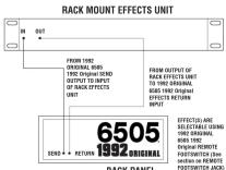
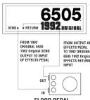
EFFECTS PATCHING
USING THE EFFECTS LOOP TO PATCH EXTERNAL, NON GAIN PRODUCING EFFECTS DEVICES (DIGITAL DELAY, REVERS, CHORUS, ETC.)


[Non-Text]

FCC/ICES Compliance Statement
This device complies with Part 15 of the FCC rules and Industry Canada license-exempt RSS Standard(s). Operation is subject to the following two conditions: (1) this device may not cause harmful interference, and (2) this device must accept any interference received, that may cause undulyed or noation.
Note - This equipment has been tested and found to comply with the limits for a Class B digital device, pursuant to Part 15 of the P.C. Rules. These limits are designed to provide reasonable protection against harmful interference in a residential installation. This
equipment generates, uses, and can radiate radio frequency energy and, if not installed and used in accordance with the instructions, may cause harmful interference to radio communications. However, there is no guarantee that interference will not occur in a particular
installation. If this equipment does cause harmful interference to radio or television reception, which can be determined by turning the equipment off and on, the movie is assigned to two and correct the interference by one or more of the following purposes.
adjustment can drill up the dose is associated to try and recover the interference by one of more as well following measures
• Reorient or relocate the receiving antenna.
- Increase the separation between the equipment and receiver.
- Connect the equipment into an outlet on a circuit different from that to which the receiver is connected. Consult the dealer or an experiorated audio/TV technician for help
- Stabilized and similar to the Experimental Data 3 - Technological Test
Caution
The equipment complies with FCC radiation exposure limits set forth for an uncontrolled environment

www.peavey.com
Warranty registration and information for U.S. customers available online at
www.peavey.com/warrant

Features and specifications subject to change without notice.
Peavey Electronics Corporation 5022 Hartley Peavey Drive Meridian, MS 39305 (601) 483-5365 FAX (601) 486-1278
Logo referenced in Directive 2002/96/EC Annex IV
The bar is the symbol for marking of new waste and
is applied only to equipment manufactured after 13 August 2005
OPERATING GUIDE


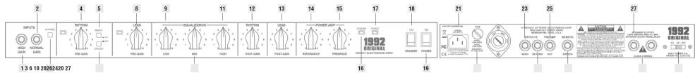
1 INPUTS
The 6505 1992 Original's input block features HIGH [1] and NORMAL [2] gain inputs. The HIGH gain input has twice the gain of the NORMAL gain input and should be used when maximum overdrive is desired. When both inputs are used simultaneously, the 6505 1992 Original automatically switches the normal gain mode (6 dB pad). Situations where both inputs are used at once (alternating between two guitars on stage using both inputs, etc.) should be avoided if peak overdrive is expected from the amp. Experimentation with your particular guitar/pickup into each input will determine which input is best for your sound.
3 CHANNEL SELECT SWITCH
Allows selection of the RHYTHM or LEAD channel. Depressing the switch to the "in" position activates the LEAD channel. The red LED light will illuminate to indicate that the LEAD channel is active. In the "out" position the RHYTHM channel is activated and the green LED illuminates. Channels may be remotely selected using the 6505 1992 Original's footswitch. If remote selection is desired the channel select switch must be set to the "in" position (LEAD channel).
8 LEAD PRE & POST GAIN
The LEAD CHANNEL PRE GAIN [8] controls the input level and works with the LEAD CHANNEL POST GAIN [13] to determine the overall volume/overdrive of the LEAD channel. Lower settings of the PRE GAIN control produce a relatively clean, undistorted sound while the middle to high settings produce harmonically rich distortion and screaming
overdrive/sustain. Since both PRE and POST GAIN controls work in "combo" a basic rule-of-thumb set-up procedure is to begin with both controls in the lower settings (0 - 2). Using the PRE GAIN control, dial in the amount of overdrive/sustain you want for the LEAD channel. Then, with the POST GAIN control adjust for overall volume.
4 RHYTHM PRE & POST GAIN
The RHYTHM channel PRE [4] and POST GAIN [12] operate in the same manner as the LEAD channel gain controls. For most applications, the RHYTHM channel should be set up with the PRE GAIN at the lower, "cleaner" settings (0 - 4) and the POST GAIN set for overall volume. The RHYTHM channel can be converted to a second "lead" channel by activating the CRUNCH SWITCH [6].
5 BRIGHT SWITCH
Activates a preset boost in the treble frequencies (6 dB at 2 kHz) and affects only the rhythm channel.
6 CRUNCH SELECT SWITCH Boosts the gain of the rhythm channel to create a second "lead" channel. Depress to the "in" position to activate.
9 EQUALIZATION
The 6505 1992 Original's
0 equalization block features
passive LOW, MID, and HIGH EQ.
1
4 RESONANCE I PRESENCE
Unique to the 6505 1992 Original,
the RESONANCE [14] control can
be set to boost the gain of the
power amp in the low frequencies
overdrive/sustain. Since both PRE and POST GAIN controls work in "combo" a basic rule-of-thumb set-up procedure is to begin with both controls in the lower settings (0 - 2). Using the PRE GAIN control, dial in the amount of overdrive/sustain you want for the LEAD channel. Then, with the POST GAIN control adjust for overall volume.
at the resonance/attenuation point of the speaker cabinet. In simple terms, the RESONANCE control works like a low EQ to offset low-end frequency drop-out. The PRESENCE [15] control works in the same manner, boosting the high frequencies. Experimentation using your particular speaker cabinet along with personal taste will determine your setting for these important controls.
18 STANDBY SWITCH
Allows the 6505 to be placed in a non-operational standby mode. When the standby switch is activated, the tubes remain hot and ready for instantaneous operation, eliminating warm-up time. The STANDBY LED indicator light [16] will illuminate when the amp is in the operational mode.
19 POWER SWITCH
Supplies power to the unit.
Depressed to the "ON" position,
the POWER LED indicator light
[17] will illuminate indicating
power is being supplied to the
unit.
20 FUSE
A 5 amp fuse is located within the cap of the fuse holder. It must be
replaced with the same type and value in order to avoid damage to the equipment and to prevent voiding the warranty. If the amp repeatedly blows fuses, it should be taken to a qualified service center for repair. WARNING: The fuse should only be replaced when the power cord has been disconnected from its power source.
power source.
21 LINE CORD (120 V units only)
For your safety, we have
incorporated a 3-wire line (mains)
cable with proper grounding
facilities. It is not advisable to
remove the ground pin under any
circumstances. If it is necessary
to use the 6505 1992 Original
without proper grounding
facilities, suitable grounding
adaptors should be used. Greatly
reduced shock hazard exists
when the unit is operated with the
proper grounded receptacles.
22 GROUND SWITCH
Three position, rocker-type switch which, for most applications, should be operated in the center (zero) position. If hum or noise is noticed coming from the speaker enclosure(s) with the ground switch in the center
position, place the ground switch to positive or negative (+or -) to minimize hum. Should a hum/ noise problem continue, consult your authorized Peavey Dealer, the Peavey factory, or a qualified service technician. NOTE: The ground switch is not functional on 220/240 volt models.
23 EFFECTS SEND I EFFECTS
RETURN
24 Signals are supplied to outboard effects or signal processing units by patching from the EFFECTS SEND [23] output into the outboard unit(s) and back into the EFFECTS RETURN [24] input using shielded cable with 1/4" phono jacks. Only non gain effects devices (chorus, reverb, delay, etc.) should be used in the effects loop. Remote (on/off) selection of outboard effects devices can be achieved using the 6505 1992 Original's footswitch.
25 PREAMP OUT
This output can be used to send a preamped signal from the 6505 1992 Original to a mixing console, tape recorder, etc., using shielded cable. Patching from the PREAMP OUT does not affect the normal operation of the amplifier.
26 REMOTE FOOTSWITCH JACK
Provided for the connection of the supplied remote footswitch. When the footswitch is plugged into the remote footswitch jack, the channel select switch [3] must be pressed to the "in" position for remote selection to operate. Remote selection of the LEAD or RHYTHM channel (left footswitch button) or outboard devices in the effects loop (right footswitch button) is possible with the remote footswitch.
SPEAKER OUTPUTS
Paralleled 14 " OUTPUTS output jacks for connecting speaker enclosure(s) to the amplifier (minimum: 4 ohms). When using more than one enclosure, be sure to calculate the total impedance and set the impedance switch [28] accordingly. (See section on IMPEDANCE SWITCH.) Important: Use only high quality, Unshielded cable for speaker connections.
IMPEDANCE SELECTOR
SWITCH Use to select the appropriate impedance of the speaker enclosure(s). If two enclosures of equal impedance are used, the switch should be set at one half of that value (e.g., two 16 ohm enclosures: set switch to 8 ohms; two 8 ohm enclosures: set switch to 4 ohms).
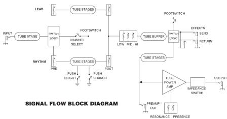
flowchart
graph TD
    A["LEAD"] --> B["TUBE STAGES"]
    C["INPUT"] --> D["TUBE STAGE"] --> E["SWITCH LOGIC"] --> F["CHANNEL SELECT"] --> G["RHYTHM"]
    G --> H["PUSH BRIGHT"] --> I["PUSH CRUNCH"] --> J["FOOTSWITCH"]
    J --> K["LOW/MD/MI"] --> L["TUBE BUFFER"] --> M["FOOTSWITCH"] --> N["EFFECTS"] --> O["SEND"]
    O --> P["RETURN"]
    Q["SIGNAL FLOW BLOCK DIAGRAM"] --> R["TUBE STAGES"]
    R --> S["TUBE POWER AMP"] --> T["INPPEDANCE SWITCH"] --> U["OUTPUT"]
    V["PREAM OUT"] --> W["RESONANCE PRESENCE"] --> X["OUTPUT"]
Brand : PEAVEY
Model : 6505 1992 Original
Category : Guitar amplifier