
ECtemp 130 - Thermostat DANFOSS - Free user manual and instructions
Find the device manual for free ECtemp 130 DANFOSS in PDF.


| Product Type | Electronic thermostat for floor heating |
| Brand | Danfoss |
| Model | ECtemp 130 |
| Power Supply Voltage | 220-240 V~, 50 Hz |
| Max Power Consumption | 5 W |
| Relay (Resistive Load) | Max 16 A / 3680 W @ 230 V |
| Relay (Inductive Load) | Max 1 A, cos φ=0.3 |
| Sensing Unit | NTC 15 kOhm at 25°C |
| Hysteresis | ±0.2 °C |
| Temperature Range | 5–45 °C |
| Frost Protection Temperature | 5 °C |
| Ambient Temperature | 0 to +30 °C |
| Storage Temperature | -20 to +65 °C |
| Ball Pressure Temperature | 75 °C |
| IP Class | IP 30 |
| Protection Class | Class II (double insulated) |
| Pollution Degree | 2 (domestic use) |
| Dimensions (W x H x D) | 82 x 82 x 36 mm |
| Weight | 90 g |
| Cable Specification | Max 1x4 mm² or 2x2.5 mm² |
| Compliance Standards | EN/IEC 60730-1, EN/IEC 60730-2-9 |
| Warranty | 2 years (conditions apply) |
| Disposal | Recycle according to local regulations |
Frequently Asked Questions - ECtemp 130 DANFOSS
User questions about ECtemp 130 DANFOSS
0 question about this device. Answer the ones you know or ask your own.
Ask a new question about this device
Download the instructions for your Thermostat in PDF format for free! Find your manual ECtemp 130 - DANFOSS and take your electronic device back in hand. On this page are published all the documents necessary for the use of your device. ECtemp 130 by DANFOSS.
USER MANUAL ECtemp 130 DANFOSS
1.1 Technical Specifications .....4
1.2 Safety Instructions .....5
2 Mounting Instructions....6
3 Settings 10
3.1 Temperature Settings..... 10
4 Warranty....14
5 Disposal Instruction ..... 16
1 Introduction
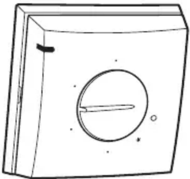
ECtemp 130 is an electronic thermostat to be installed directly on the wall. It is provided with a floor sensor to measure and control the desired floor temperature.
The thermostat has a button for adjusting the temperature setting with a scale from (⏻) 1 to 5 (each step corresponds to approximately 9°C). Furthermore, the thermostat has an LED indicator showing standby periods (green light) and heating periods (red light).
More information on this product can also be found at: ectemp.danfoss.com
1.1 Technical Specifications
| Operation voltage 220-240V~, 50Hz | |
| Power consumption Max 5W | |
| Relay: | |
| Resistive load | Max 16A / 3680W @ 230V |
| Inductive load | cos φ= 0.3 max 1A |
| Sensing units NTC 15 kOhm at 25°C | |
| Sensing values: | |
| 0 °C | 42 kOhm |
| 25 °C | 15 kOhm |
| 50 °C | 6 kOhm |
| Hysteresis ± 0,2 °C | |
| Ambient temperature 0 to +30°C | |
| Frost protection temperature | 5 °C - ✉ |
| Temperature range | (○) 5–45 °C |
| Cable specification max | 1x4 mm2 or 2x2,5 mm2 |
| Ball pressure temperature | 75 °C |
| Pollution degree Degree 2 (domestic use) | |
| Type 1C | |
| Storage temperature -20 to +65°C | |
| IP class 30 | |
| Protection class | Class II - □ |
| Dimensions 82 x 82 x 36 mm | |
| Weight 90 g | |
The product complies with the EN/IEC Standard «Automatic electrical controls for household and similar use»:
• EN/IEC 60730-1 (general)
• EN/IEC 60730-2-9 (thermostat)
1.2 Safety Instructions
Make sure the mains supply to the thermostat is turned off before installation.
IMPORTANT: When the thermostat is used to control a floor heating element in connection with a wooden floor or similar material, always use a floor sensor and never set the maximum floor temperature to more than 35^ C.
Please also note the following:
- The installation of the thermostat must be done by an authorized and qualified installer according to local regulations.
- The thermostat must be connected to a power supply via an all-pole disconnection switch.
- The sensor is to be considered as live voltage. Have this in mind if the sensor must be extended.
• Always connect the thermostat to continuous power supply.
- Do not expose the thermostat to moisture, water, dust, and excessive heat.
2 Mounting Instructions
Please observe the following placement guidelines:
natural_image
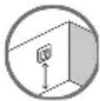
Simple line drawing of a room with a wall-mounted device and a vertical line, enclosed in a circle (no text or symbols)Place the thermostat at a suitable height on the wall (typically 80-170cm.).

In wet rooms, place the thermostat according to local regulation on IP classes.

Do not place the thermostat on the inner side of an exterior wall.
natural_image
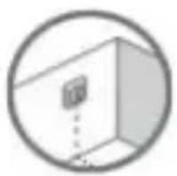
Simple line drawing of a 3D box with a small inset image, enclosed in a circular border (no text or symbols)- Place the floor sensor in a conduit in an appropriate place where it is not exposed to sunlight or draft from door openings.
• Equally distant and >2cm from two heating cables.
- The conduit should be flush with the floor surface - countersink the conduit if necessary.
- Route the conduit to the connection box.
- The bending radius of the conduit must be min 50mm.
Follow the steps below to mount the thermostat:
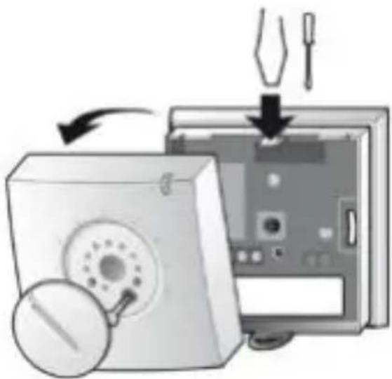
1. Open the thermostat:
natural_image
Illustration of a washing machine with a magnifying glass and screwdriver, showing internal components (no text or symbols)- Lift off the button using a small screwdriver.
- Loosen the screw which holds the front.
- Push down the release tab at the top of the thermostat using a flat object while slowly pulling off the front cover.
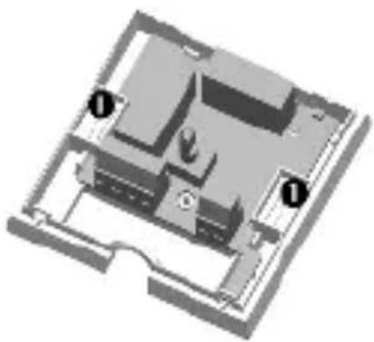
- Fasten the thermostat directly to the wall by driving the screws through the holes in each side of the thermostat.
natural_image
3D architectural or mechanical component diagram with numbered annotations (1) indicating specific parts, no readable text or symbols present.1 = Screw holes for fastening the thermostat.
- Connect the thermostat according to the connectiondiagram.
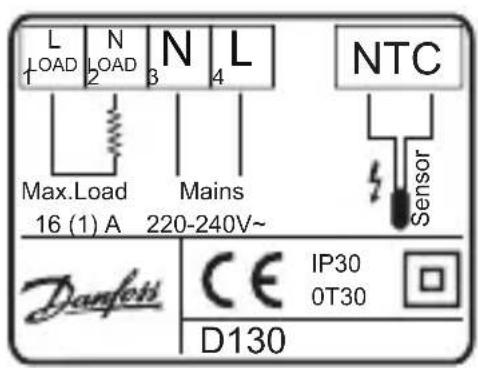
The screen of the heating cable must be connected to the earth conductor of the power supply cable by using a separate connector.
Note: Always install the floor sensor in a conduit in the floor.
- Install the front cover and button in the reverse order of disassembly.
- Turn on the power supply.
3 Settings
3.1 Temperature Settings
How to change the minimum and maximum floor temperatures
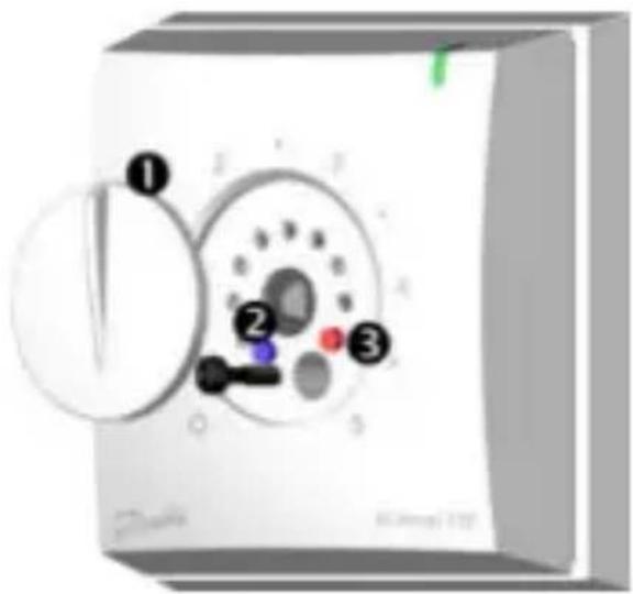
- Lift off the adjustment button using a thin screwdriver. (1)
- Move the pins to the desired positions. (2 and 3)
- Put the adjustment button back in place.
Please be aware of the following:
- The floor temperature is measured where the sensor is placed.
- The temperature of the bottom of a wooden floor can be up to 10 degrees higher than the top.
- Floor manufactures often specify the max temperature on the top surface of the floor (usually 27-28°C).
- By default, the maximum floor temperature is set to 35^ C .
• Always use a floor sensor or a room + floor sensor combination to control floor heating. Without a floor sensor, the temperature control may be less accurate and you risk overheating the floor.
| Thermal resistance [m2K/W] | Examples of flooring | Details Approximate setting for 25 °C floor temperature |
| 0,058 mm HDF based laminate | >800 kg/m3 | 28 °C |
| 0,1014 mm beech parquet | 650–800 kg/m3 | 31 °C |
| 0,1322 mm solid oak plank | >800 kg/m3 | 32 °C |
| <0,17 Max. carpet thickness suitable for floor heating | acc. to EN 1307 | 34 °C |
| 0,1822 mm solid fir planks | 450–650 kg/m3 | 35 °C |
4 Warranty
A 2-year product warranty is valid for:
- thermostats: ECtemp 130.
Should you, against all expectations, experience a problem with your Danfoss product, you will find that Danfoss offers Danfoss warranty valid from the date of purchase on the following conditions: During the warranty period Danfoss shall offer a new comparable product or repair the product if the product is found to be faulty by reason of defective design, materials or workmanship. The repair or replacement.
The decision to either repair or replace will be solely at the discretion of Danfoss. Danfoss shall not be liable for any consequential or incidental damages including, but not limited to, damages to property or extra utility expenses. No extension of the warranty period following repairs undertaken is granted.
The warranty shall be valid only if the WARRANTY CERTIFICATE is completed correctly and in accordance with the instructions, the fault is submitted to the installer or the seller without undue delay and proof of purchase is provided. Please note that the WARRANTY CERTIFICATE must be filled in, stamped and signed by the authorized installer performing the installation (Installation date must be indicated). After the installation is performed, store and keep the WARRANTY CERTIFICATE and purchase documents (invoice, receipt or similar) during the whole warranty period.
Danfoss warranty shall not cover any damage caused by incorrect conditions of use, incorrect installation or if installation has been carried out by non-authorized electricians. All work will be invoiced in full if Danfoss is required to inspect or repair faults that have arisen as a result of any of the above. The Danfoss warranty shall not extend to products which have not been paid in full. Danfoss will, at all times, provide a rapid and effective response to all complaints and inquiries from our customers.
The warranty explicitly excludes all claims exceeding the above conditions.
For full warranty text please use QR code

| WARRANTY CERTIFICATE | |
| The Danfoss warranty is granted to: | |
| Address Stamp | |
| Purchase date | |
| Serial number of the product | |
| Product Art. No. | |
| *Connected output [W] | |
| Installation Date & Signature | Connection Date & Signature |
| *Not mandatory | |

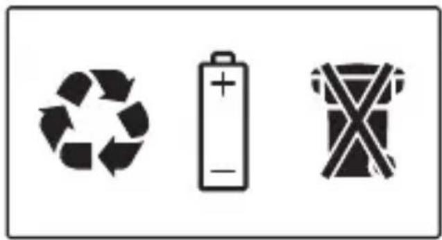
5 Disposal Instruction
natural_image
Three black-and-white icons: a recycling symbol, a battery with plus sign, and a crossed-out envelope (no text or labels)Danfoss A/S
Nordborgvej 81
6430 Nordborg, Syddanmark
Denmark
Danfoss A/S
Climate Solutions · danfoos.com · +45 7400 2222
Any information, including, but not limited to information on retention of product, its application or use product design, weight dimensions, capacity or any other technical data in product manual, catalogous descriptions, advertisements, etc. and whether made available in writing, serial, electronically or the written document, shall be covered information, and to be binding if and to the extent, request reference is made in a quotation or initial confirmation. Dariffs cannot accept any responsibility for possible results in cataloging, vendors, stores and other material Dariffs reserved the right to alter products without notice. This also applies to products ordered but not deferred provided that such information can be made without changes to form, fit or function of the product.
All materials in this material are properly of Dariffs A/S or Dariffs group companies. Dariffs and the Dariffs logo are trademarks of Dariffs A/S. All rights reserved.

natural_image
Simple line drawing of a rectangular box containing a circular object with a vertical line inside, and a small black object at the bottom (no text or symbols)
088L0030 ECtemp 130
IP 30 16A/3680W@230V\~ +5 to +45°C 50-60Hz\~ 220-240V\~
(N) ∃)
- Mounting Instructions....6
- Settings 10
- Warranty....14
- Disposal Instruction ..... 16
- Introduction
- Technical Specifications
- Safety Instructions
- Mounting Instructions
- Follow the steps below to mount the thermostat:
- Open the thermostat:
- Settings
- Temperature Settings
- How to change the minimum and maximum floor temperatures
- Warranty
- A 2-year product warranty is valid for:
- Disposal Instruction
Brand : DANFOSS
Model : ECtemp 130
Category : Thermostat