
Quick Step Base Stand - Lighting Savage - Free user manual and instructions
Find the device manual for free Quick Step Base Stand Savage in PDF.


| Product Type | Lighting Stand Base |
| Brand | Savage |
| Model | Quick Step Base Stand |
| Receiver Size | 5/8" (16 mm) for standard baby pins and adapters |
| Ball Head Capacity | 8 lbs (3.63 kg) with 40" (102 cm) gobo arm |
| Base Capacity (without anchoring) | 1.6 lbs (0.73 kg) with 40" gobo arm |
| Anchoring Options | Sandbags over legs or bolting via 3/8" threads on each leg |
| Adjustment Mechanism | Quick-release foot pedal for angle adjustment |
| Ball Head Tension | Adjustable via included No. 6 Allen wrench |
| Included Accessories | No. 6 Allen wrench |
| Material | Steel and aluminum (typical) |
| Usage | Supporting lights, grip arms, gobo arms, and other equipment |
| Safety Note | Use sandbags or bolt to floor for loads exceeding 1.6 lbs with 40" arm |
| Cleaning | Wipe with a dry, soft cloth |
| Maintenance | Check ball head tension periodically; tighten as needed |
Frequently Asked Questions - Quick Step Base Stand Savage
User questions about Quick Step Base Stand Savage
0 question about this device. Answer the ones you know or ask your own.
Ask a new question about this device
Download the instructions for your Lighting in PDF format for free! Find your manual Quick Step Base Stand - Savage and take your electronic device back in hand. On this page are published all the documents necessary for the use of your device. Quick Step Base Stand by Savage.
USER MANUAL Quick Step Base Stand Savage
Thank you for purchasing the Savage Quick Step Stand Base. Please read this instruction manual before use, and keep for later reference.
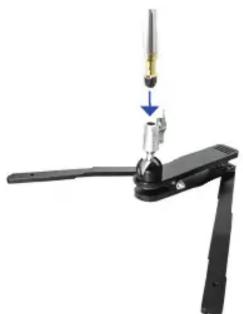
natural_image
Mechanical assembly diagram showing a tool interacting with a mechanical bracket (no text or symbols visible)ATTACH GRIP ARM OR LIGHT TO RECEIVER
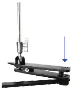
natural_image
Mechanical lever mechanism with a downward arrow indicating force or motion (no text or symbols visible)PRESS FOOT PEDAL TO ADJUST ANCHOR TO FLOOR OR USE SANDBAGS
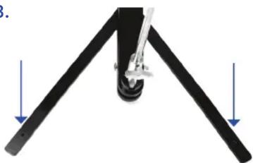
natural_image
Mechanical assembly diagram showing two black rods with a central knob and a vertical rod inserted, no text or symbols present.4.5.
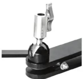
natural_image
Close-up of a mechanical clamp or bracket component with metallic and black parts (no visible text or symbols)BALL HEAD CAN SUPPORT UP TO 8LBS ADJUST TENSION USING ALLEN WRENCH
natural_image
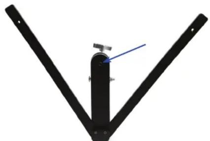
Black V-shaped mechanical structure with a blue arrow pointing to a central component (no text or symbols visible)1) Attach a light or other support gear using a standard 5/8" adapter or baby pin by placing it inside the middle receiver and tightening the thumb screw on the side.
2) While holding on to the light or other support mounted, press the foot pedal to reposition to the angle of your choice, then release the pedal fully to lock in place.
3) Use sandbags over the base legs, or bolt to the floor using the 3/8" threads located at the front of each leg, for weight exceeding 1.6 lbs. (0.73kg) when using a 40" (102cm) gobo arm.
4) Ball head will hold 8 lbs. (3.63kg) without slipping using a standard 40" gobo arm.
5) To decrease/increase the tension and capacity of the ball head, loosen/tighten using using the included no. 6 allen wrench on the bottom of the stand base beneath the ball head.
Brand : Savage
Model : Quick Step Base Stand
Category : Lighting