
LS1024EU - Uncategorized POLAROID - Free user manual and instructions
Find the device manual for free LS1024EU POLAROID in PDF.

| Product Type | PWM Solar Charge Controller |
| Model | LS1024EU |
| Nominal System Voltage | 12/24V auto |
| Rated Charge Current | 10A |
| Rated Discharge Current | 10A |
| Max. PV Open Circuit Voltage | 50V |
| Battery Input Voltage Range | 8~32V |
| Battery Types Supported | Sealed (default), Gel, Flooded |
| Charging Algorithm | 3-Stage PWM: Bulk, Boost/Equalize, Float |
| USB Output | 5VDC / 1.2A |
| Temperature Compensation | -5mV/°C/2V |
| Enclosure Rating | IP20 |
| Grounding | Common Positive |
| Dimensions (L x W x H) | 120.3 x 67 x 21.8 mm |
| Weight | 100 g |
| Terminals | 12 AWG / 4 mm² |
| Self-Consumption | ≤5mA (12V); ≤7mA (24V) |
| Working Temperature | -35°C to +55°C |
| Humidity | ≤95% N.C. |
| Protections | Overvoltage, Overdischarge, Overload, Short Circuit, High Voltage Transients |
| Mounting Hole Size | ø4.5 mm |
| Warranty | Limited warranty; see manual for conditions |
Frequently Asked Questions - LS1024EU POLAROID
User questions about LS1024EU POLAROID
0 question about this device. Answer the ones you know or ask your own.
Ask a new question about this device
Download the instructions for your Uncategorized in PDF format for free! Find your manual LS1024EU - POLAROID and take your electronic device back in hand. On this page are published all the documents necessary for the use of your device. LS1024EU by POLAROID.
USER MANUAL LS1024EU POLAROID
1. Safety Information
- Read all of the instructions in the manual before installation.
• DO NOT disassemble or attempt to repair the controller.
• Install external fuse or breaker as required. - Do disconnect the solar module and fuse/ breakers near to battery before installing or moving the controller.
- Power connections must remain tight to avoid excessive heating from a loose connection.
- Only charge batteries that comply with the parameters of controller.
- Battery connection may be wired to one battery or a bank of batteries.
- Risk of electric shock, the PV and load can produce high voltages when the controller is working.
2. Overview
The Polaroid Solar Charge Controller is a PWM charge controller that adopts the most advanced digital technique. It's an easy operation and cost efficient controller featured as:
• 3-Stage intelligent PWM charging: Bulk, Boost/Equalize, Float
• Support 3 charging options: Sealed, Gel, and Flooded
- Battery status LED indicator can indicate battery situation
- Battery temperature compensation function
- With humanized settings, operation will be more comfortable and convenient
- The USB will provide power supply that can charge for electronic equipment
- Battery type and load output can be set via button
- Extensive Electronic protection
3. Product Features
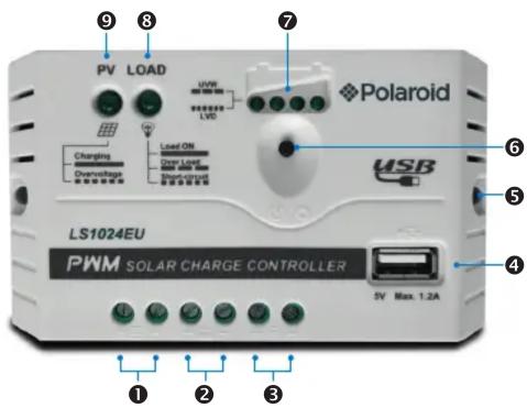
| 1 PV Terminals 6 Load Switch Button | |
| 2 Battery Terminals 7 Battery status LED indicator | |
| 3 Load Terminals 8 Load status LED indicator | |
| 4 USB output interface 9 Charging status LED indicator | |
| 5 Mounting Hole ø4.5mm | |
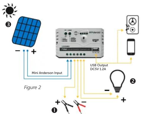
4. Wiring
Connect the system in the order of ① battery → ② load → ③ PV array and disconnect the system in the reverse order ③ ② ① (see figure 2).
NOTE: While wiring the controller do not close the circuit breaker or fuse and make sure that the leads of „+“ and „-“ poles are connected correctly.
NOTE: A fuse which current is 1.25 to 2 times the rated current of the controller must be installed on the battery side with a distance from the battery not greater than 150 mm.
NOTE: If an inverter is to be connected to the system, connect the inverter directly to the battery, not to the load side of the controller.
5. LED Indicators
- Charging and load status indicator
| Indicator Color | Status Introduction | ||
| Charging status LED indicator | Green ON | Charging | |
| Green | OFF | Not charging | |
| Green | Fast fl ashing | Battery over voltage | |
| Load status LED indicator | Green ON | Load ON | |
| Green | OFF | Load OFF | |
| Green | Slowly fl ashing | Load overload | |
| Green | Fast fl ashing | Load short circuit | |
- Battery status indicator
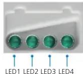
| LED1 | LED2 | LED3 | LED4 Battery Status | |
| Slowly flashing | × | × | × | Under voltage |
| Fast flashing | × | × | × | Over discharge |
| Battery LED indicator status during voltage is up | ||||
| o | o | × | × | 12.8V < Ubat < 13.4V |
| o | o | o | × | 13.4V < Ubat < 14.1V |
| o | o | o | o | 14.1V < Ubat |
| Battery LED indicator status during voltage is down | ||||
| o | o | o | × | 12.8V < Ubat < 13.4V |
| o | o | × | × | 12.4V < Ubat < 12.8V |
| o | × | × | × | Ubat < 12.4V |
NOTE:
1) Voltage value for 12V system at 25^ C, please use 2x in 24V system
2) "o"LED indicator on | „×"LED indicator off.
6. Setting operation
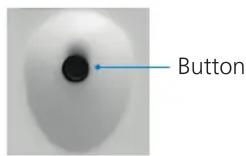
1) Load ON/OFF Setting
When the controller is powered on, press the button to control the load output.
2) Battery Type Setting
Operation:
Step 1: Enter setting mode by pressing button for 5s until the battery status LEDs are fl ashing.
Step 2: Select the desired mode by pressing button.
Step 3: The mode will be saved automatically without any operation for 5 seconds and LED will stop fl ashing.
Battery type indicator
| LED1 | LED2 | LED3 | Battery type |
| o | × | × | Sealed (Default) |
| o | o | × | Gel |
| o | o | o | Flooded |
Note: "o"LED indicator on | „×"LED indicator off
6. Setting operation
Battery Voltage Control Parameters
Below parameters are for 12V systems at 25^ C. Please double the values for 24V systems.
| Sealed Gel Flooded | |||
| Over Voltage Disconnect Voltage 16.0V | 16.0V 16.0V | ||
| Charging Limit Voltage 15.0V 15.0V | 15.0V | ||
| Over Voltage Reconnect Voltage 15.0V | 15.0V 15.0V | ||
| Equalize Charging Voltage 14.6V —— | 14.8V | ||
| Boost Charging Voltage 14.4V 14.2V | 14.6V | ||
| Float Charging Voltage 13.8V 13.8V | 13.8V | ||
| Boost Reconnect Charging Voltage 13.2V | 13.2V 13.2V | ||
| Low Voltage Reconnect Voltage 12.6V | 12.6V 12.6V | ||
| Under Voltage WarningReconnect Voltage | 12.2V 12.2V | 2V 12.2V | |
| Under Voltage Warning Voltage 12.0V | 12.0V 12.0V | ||
| Low Voltage Disconnect Voltage 11.1V | 11.1V 11.1V | ||
| Discharging Limit Voltage 10.6V 10.6V | 10.6V | ||
| Equalize Duration | 120 min. | —120 min. | |
| Boost Duration | 120 min. | 120 min. | 120 min. |
7. Protection
Battery Over Voltage Protection
When the battery voltage reaches to the set point of Over Voltage Disconnect Voltage (OVD), the controller will stop charging the battery to protect the battery from being over charged to break down.
Battery Over Discharge Protection
When the battery voltage reaches to the set point of Low Voltage Disconnect Voltage (LVD), the controller will stop discharging the battery to protect the battery from being over discharged.
Load Overload Protection
Load will be switched off when 1.25 times rated current overload happens. User has to reduce load appliance, then press the button or repower the controller.
Load Short Circuit Protection
Load will be switched off when load short circuit ( ≥ 3 times rated current) happens. User has to clear short circuit, then press the button or repower the controller.
High Voltage Transients Protection
The controller is protected against small high voltage transients. In lightning prone areas, additional external suppression is recommended.
- Troubleshooting
| Faults | Possible reasons Troubleshooting | |
| LED Charging indicator turn off during daytime when sunshine falls on PV modules properly | PV array disconnection | Confirm that PV and battery wire connections are correct and tight |
| No LED indicator | Battery voltage maybe less than 8V | Measure battery voltage with the multi-meter. Min. 8V can start upthe controller |
| Charging status LED indicator Fast flashing | Battery Over Voltage | Check if battery voltage is higher than OVD, and disconnect the PV |
| LED1 Fast flashing | Battery over discharged | When the battery voltage is restored to or above LVR point (low voltage reconnect voltage), the load will recover |
| Load status LED indicator slowly flashing | Load over load* | 1) Please reduce the number of electric equipments2) Press the button or repower the controller |
| Load status LED indicator fast flashing | Load short circuit | 1) Check carefully loads connection, clear the fault2) Press the button or repower the controller |
*When load current reaches 1.25 times, 1.5 times and 2 times more than nominal value, the controller will automatically turn off loads in 60s, 5s and 1s respectively.
- Technical Parameters
| Nominal system voltage | 12/24V auto |
| Rated charge current | 10A |
| Rated discharge current | 10A |
| Battery input voltage range | 8~32V |
| Max. PV open circuit voltage 50V | |
| Equalize charging voltage | Gel: -Sealed: 14.6VFlooded: 14.8V |
| Boost charging voltage | Gel: 14.2VSealed: 14.4VFlooded: 14.6V |
| Float charging voltage | Gel: 13.8VSealed: 13.8VFlooded: 13.8V |
| Low voltage reconnect voltage | Gel: 12.6VSealed: 12.6VFlooded: 12.6V |
| Low voltage disconnect voltage | Gel: 11.1VSealed: 11.1VFlooded: 11.1V |
| USB output port | 5VDC/1.2A |
| Charge circuit voltage drop | ≤0.13V |
| Discharge circuit voltage drop | ≤0.17V |
| Self-consumption | ≤5mA(12V); ≤7mA (24V) |
| Temp. compensation | -5mV/oC/2V |
| Enclosure | IP20 |
| Grounding | Common Positive |
| Overall dimension | 120.3 x 67 x 21.8mm |
| Mounting dimension | 111.5mm |
| Mounting hole size | ø4.5mm |
| Terminals | 12AWG / 4mm2 |
| Net weight | 100 gr |
| Working temperature | -35oC - +55oC |
| Humidity | ≤95% N.C. |
10. Disclaimer
This warranty does not apply under the following conditions:
- Damage from improper use or use in an unsuitable environment.
- PV or load current, voltage or power exceeding the rated value of controller.
- User disassembly or attempted repair the controller without permission.
- The controller is damaged due to natural elements such as lighting.
- The controller is damaged during transportation and shipment.
- Any changes to this manual can be done without prior notice!
11. Warranty and customer service
Germany / EU
GBT GmbH
An Gut Nazareth 18A
52353 Dueren
Telephone: +49 (0) 2421 / 20 85 60
E-Mail: info@gbt-international.com
Finland
Pro Technic
Sierakiventie 8
02780 Espoo
Telephone: +358 (0) 9 4393 230
Portable Power Supplies
430 Newman Rd.
Geebung QLD 4034
E-Mail: hello@portablepowersupplies.com.au
For further manuals in different languages please visit our website:
www.polaroidenergystorage.com or www.gbt-international.com/manuals
- Safety Information
- Overview
- Product Features
- Wiring
- LED Indicators
- Setting operation
- Operation:
- Battery Voltage Control Parameters
- Protection
- Battery Over Voltage Protection
- Battery Over Discharge Protection
- Load Overload Protection
- Load Short Circuit Protection
- High Voltage Transients Protection
- Disclaimer
- Warranty and customer service
- Germany / EU
- GBT GmbH
- Finland
- Pro Technic
- Portable Power Supplies
Brand : POLAROID
Model : LS1024EU
Category : Uncategorized