
FlipX FLX-A-AM - Uncategorized OPTEX - Free user manual and instructions
Find the device manual for free FlipX FLX-A-AM OPTEX in PDF.


| Type of product | Flexible Range Indoor Detector (PIR + Anti-masking) |
| Brand | Optex |
| Model | FlipX FLX-A-AM |
| Detection method | Passive infrared (PIR) with anti-masking |
| Coverage (Wide) | 15 m (50 ft), 85° |
| Coverage (Narrow) | 24 m (80 ft), 5° (MW detection disabled) |
| Detection zones (Wide) | 80 zones |
| Detection zones (Narrow) | 20 zones |
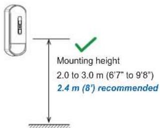
| Mounting height | 2.0 to 3.0 m (6'7" to 9'8") |
| Alarm period | 2.0 ± 0.5 s |
| Warm-up period | Approx. 60 s (LED blinks) |
| Power input | 9.5 to 16 V DC |
| Current draw | 12 mA (normal), 16 mA (max) at 12 V DC |
| Relay outputs | Trouble, Alarm, Tamper (N.C., 24 V DC, 0.1 A max) |
| Dimensions (H x W x D) | 159.1 x 62.2 x 55.7 mm (6.26 x 2.45 x 2.19 in) |
| Weight | Approx. 180 g (6.35 oz) |
| Operating temperature | -20°C to +50°C (-4°F to +122°F) |
| Humidity | 95% max |
| RF immunity | 10 V/m (no alarm) |
| LED indicator | Multi-color (Green/Red/Yellow), switchable |
| Anti-masking | Detects objects covering lens >20 sec, outputs alarm and trouble |
| Security grade | EN 50131-1 Grade 3, Environmental Class II |
| Installation | Wall, corner (indoor); optional bracket for ceiling |
| Maintenance | Walk test at least once a year; keep lens clean and unobstructed |
| Spare parts & repairability | Contact OPTEX for replacement parts; repair by qualified personnel |
Frequently Asked Questions - FlipX FLX-A-AM OPTEX
User questions about FlipX FLX-A-AM OPTEX
0 question about this device. Answer the ones you know or ask your own.
Ask a new question about this device
Download the instructions for your Uncategorized in PDF format for free! Find your manual FlipX FLX-A-AM - OPTEX and take your electronic device back in hand. On this page are published all the documents necessary for the use of your device. FlipX FLX-A-AM by OPTEX.
USER MANUAL FlipX FLX-A-AM OPTEX
natural_image
Line drawing of a cylindrical device with a central control panel (no text or symbols)Flexible Range Indoor Detector
FlipX series
ADVANCED MODELS
| Wide/Narrow area Flip lens | PIR Anti-masking Microwave | ||||||
| FLX-A-AM √ √ | √ | - | |||||
| FLX-A-DAM-X5 *1 | √ | √ | √ | √ (10.525 GHz) | |||
| FLX-A-DAM-X8 *2 | √ | √ | √ | √ (10.587 GHz) | |||
| FLX-A-DAM-X9 *3 | √ | √ | √ | √ (9.425 GHz) | |||
EN
<< Contents >>
Before installation
- Manufacturer's statement
- Parts identification
- Anti-masking
Page
2
3
3
*1 Not certified to INCERT, NF
*2 Not certified to UL and SBSC
13 Not certified to EN 50131-2-4, NF, INCERT, SBSC and UL

flowchart
graph TD
    A["1 Installation"] --> B["Disassemble"]
    B --> C["Wall mount without bracket"]
    C --> D["Wiring"]
    D --> E["Settings"]
    E --> F["Wide/Narrow setting"]
    F --> G["EOL settings"]
    G --> H["DIP switch settings"]
    H --> I["Volume setting"]
    I --> J["Down zone ON/OFF"]
    J --> K["Checking3"]
Before installation
- Manufacturer's statement
Symbol Meaning

Warning
Failure to follow the instructions provided with this indication and improper handling may cause death or serious injury.

Caution
Failure to follow the instructions provided with this indication and improper handling may cause injury and/or property damage.
Symbol Meaning


NOTE
Check mark indicates recommendation.
Nix sign indicates prohibition.
Special attention is required to the section of this symbol.


Outdoor installation

Wetting with water

Warning

Detection through glass
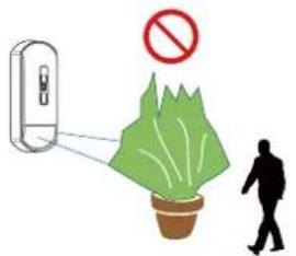
Partial/complete obscuration of the detection area.
![[ FLX-A-DAM only ] < 1 m Face to face/Back interference](/content/2026/05/848386/images/da9c633b35d755223df5ad1579a01b59c2b01ce766dcbf68ba36e5645230295e.jpg)

Caution



natural_image
Illustration of a kitchen appliance with a prohibition symbol (no text or labels)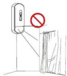



natural_image
Illustration of a person disposing of trash into two bins with recycling symbols, one marked by a green checkmark (no text or labels)Follow to the regulations
- Parts identifications

Accessories

Mount screw x 2

Wall tamper screw x 1
Options
CW-G3 *: Bracket for wall/ceiling mount
with tamper switch

PEU: Plug-in EOL Unit

* Not certified to EN 50131-2-2/EN 50131-2-4, INCERT and SBSC
- Anti-masking
Overview of anti-masking
If the front of the lens is covered with obstacles over 20 seconds, an alarm and trouble will be output.
Sensitivity setting
(Refer to "2-3 Dip switch/Volume settings" - " ④ ⑤ Anti-masking sensitivity")
Normally, use it in "Middle".
Select the "High" setting if required by any standards or sensitivity is insufficient.
If there are many false alarms, you can use "Low", but please note that it may not be output depending on the materials and colors of the obstacles.
1 Installation
1- 1. Disassemble
1 Unlock the cover

2 Open the cover

NOTE
You do not need to remove the terminal block
if it does not interfere with the mounting of the base.
1 Wire through the base

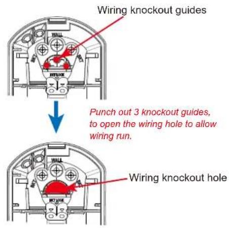
How to break the knockouts
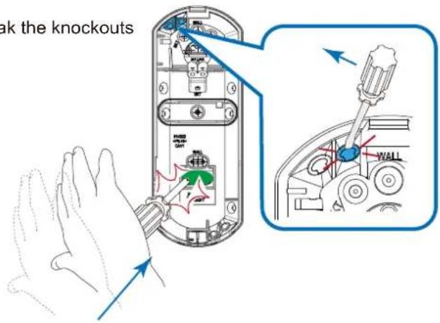
A. Surface wiring

A-2. Lower
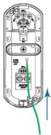

B. Hidden wiring

2 Mount the base
Mounting holes

a. Wall mount
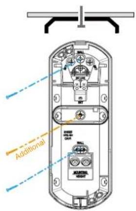
b. Corner mount


Go to 8
1 Wire and mount on the wall

NOTE
See page 5 for how to break the knockouts.
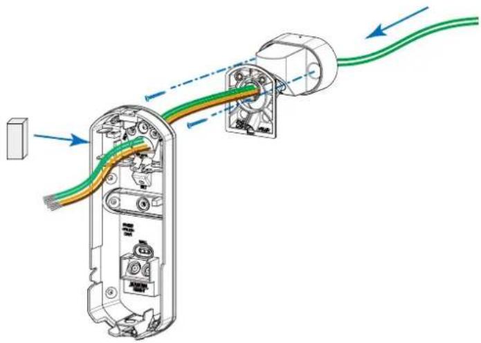
natural_image
Diagram of a device's cable and wiring assembly, showing internal components and connections (no text or labels)2 Join the base on the bracket

NOTE
Adjust the detection direction while jointing.
Confirming with a walk test is required.
--> Refer to "3-1. Walk test"
3 Fix the base with the fixing screws

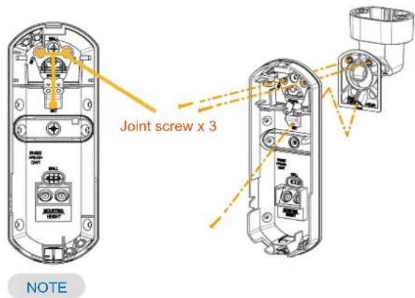
The bracket is basically jointed using 3 holes and 3 joint screws.
Also use 2 additional fixing holes if stronger support is required.
How to change the bracket to the ceiling mounting
[1] Loosen the fixing screw. [2] Rotate the body.
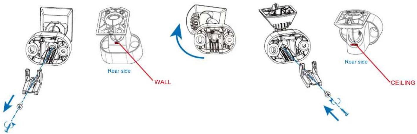
[3] Tighten the fixing screw.
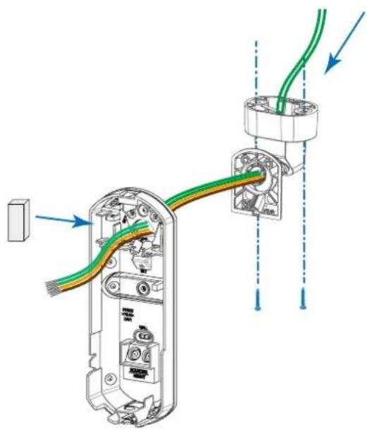
1 Wire and mount on the ceiling
NOTE
See page 5 for how to break the knockouts.
natural_image
Diagram of a device's cable and wiring assembly, showing exposed internal components and connections (no text or labels)2 Join the base on the bracket
Adjust the detection direction while jointing.
Confirming with a walk test is required.
--> Refer to "3-1. Walk test"
3 Fix the base with the fixing screws

The bracket is basically jointed
using 3 holes and 3 joint screws.
Also use 2 additional fixing holes
if a stronger fixation is required.
1-5. Wiring
1 Wire to the terminal block

2 Attach the terminal block to the base

Power cable length
The power cable should be limited to the following length.
FLX-A-AM
| WIRE GAUGE | 12 V DC | 14 V DC |
| AWG 22(0.33 mm2) | 360 m(1,180 ft.) | 780 m(2,560 ft.) |
| AWG 20(0.52 mm2) | 570 m(1,870 ft.) | 1,230 m(4,040 ft.) |
| AWG 18(0.83 mm2) | 900 m(2,950 ft.) | 1,960 m(6,430 ft.) |
FLX-A-DAM
| WIRE GAUGE | 12 V DC | 14 V DC |
| AWG 22(0.33 mm2) | 270 m(890 ft.) | 590 m(1,940 ft.) |
| AWG 20(0.52 mm2) | 430 m(1,410 ft.) | 940 m(3,080 ft.) |
| AWG 18(0.83 mm2) | 690 m(2,260 ft.) | 1,490 m(4,890 ft.) |
NOTE
How to wire to the tamper switch on the CW-G3.

2 Settings
2-1. Wide/Narrow setting
Go to 2-2 on Page 11 to skip 2-1 when using the default "Wide" setting.
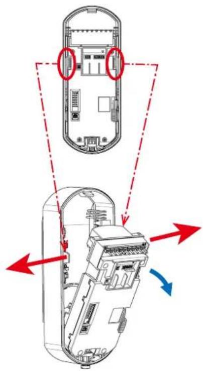
1 Remove the main unit
NOTE
- Opening the hooked part as the red arrows indicate makes it easy to take out the main unit.
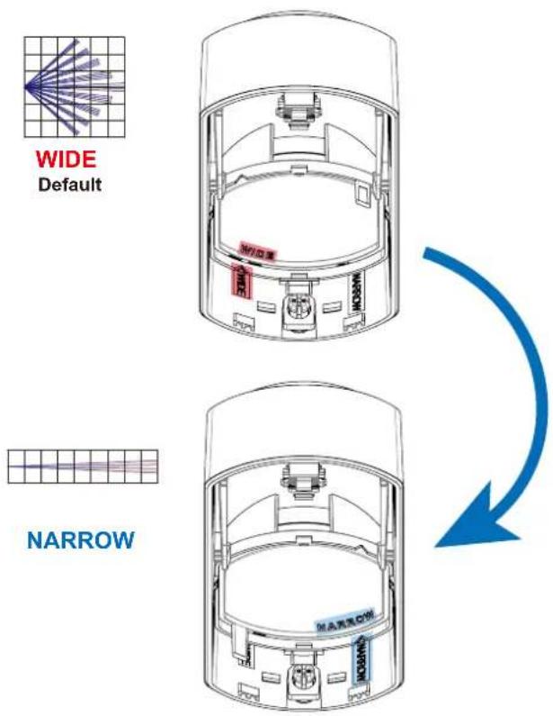
2 Change the Flip lens from "Wide" to "Narrow"
NOTE
• Install the lens so that the letters on the cover and on the lens match your intention.
- By changing the lens setting, the internal circuit automatically switches between Narrow and Wide.


- By changing the lens, the internal settings of "Wide" and "Narrow" are automatically switched. It is not necessary to change the settings such as DIP switches.
- When the lens is set to the "Narrow" position, MW detection will be disabled automatically.
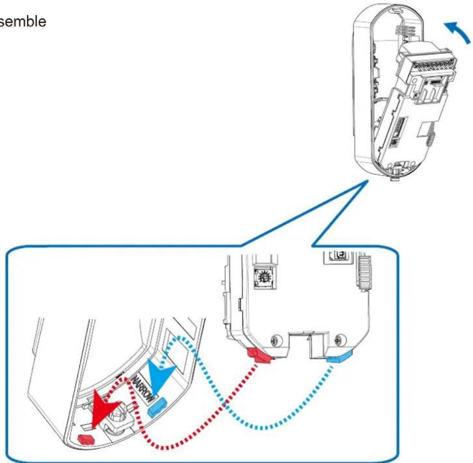
3 Assemble
2-3. EOL settings
Select whether to use the EOL resistor (End Of Line resistor) socket for
[1] PEU (option sold separately), or
[2] Processing lead wires of the resistors (not included)

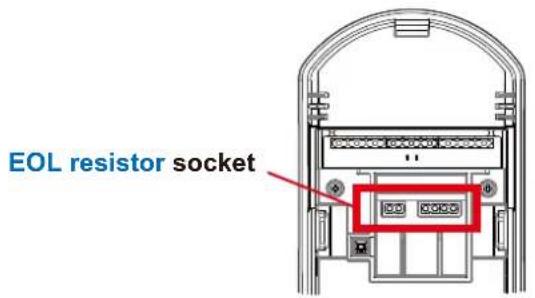
[1] PEU: Plug-in End of line resistor Unit
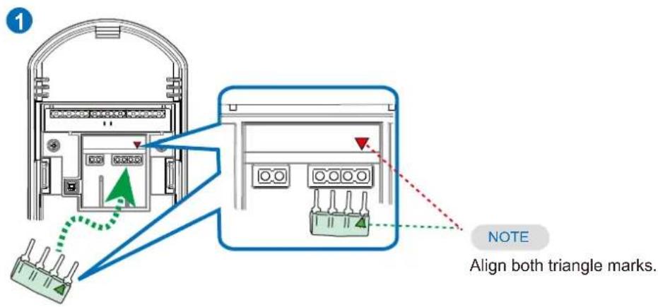

[2] Processing lead wires of the resistors


natural_image
Technical line drawing of an electrical enclosure with internal components (no text or symbols)2-3. DIP switch settings
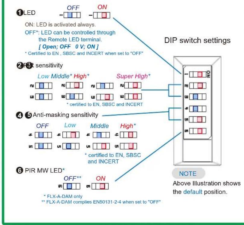
flowchart
graph TD
    A["①LED"] --> B["OFF"]
    A --> C["ON"]
    B --> D["②RFX sensitivity"]
    C --> E["②RFX sensitivity"]
    D --> F["④Anti-masking sensitivity"]
    E --> G["④Anti-masking sensitivity"]
    F --> H["⑥PIR MW LED*"]
    G --> I["NOTE: Above Illustration shows the default position."]
    style A fill:#f9f,stroke:#333
    style B fill:#ccf,stroke:#333
    style C fill:#cfc,stroke:#333
    style D fill:#fcc,stroke:#333
    style E fill:#cff,stroke:#333
    style F fill:#ffc,stroke:#333
    style G fill:#cfc,stroke:#333
    style H fill:#fcc,stroke:#333
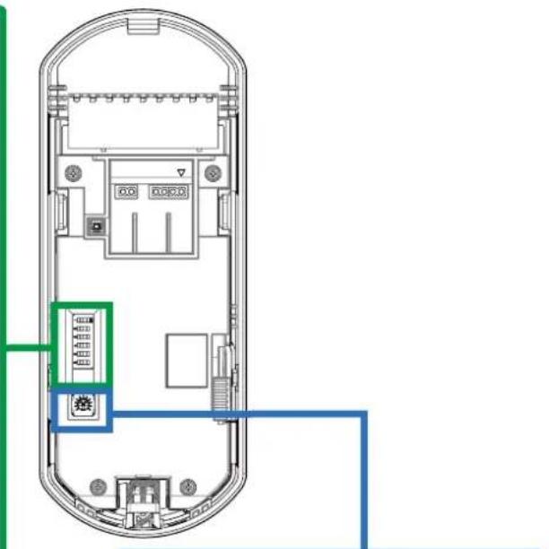
2-4. Volume setting
[FLX-A-DAM only] Microwave sensitivity
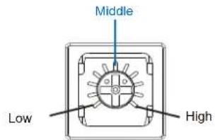
Illustration shows the default position.

natural_image
Top-down schematic of a mobile phone casing showing internal components and a highlighted red section (no text or labels)2-5. Down zone ON/OFF

flowchart
graph TD
    A["Left Vehicle"] --> B["OFF (Default)"]
    B --> C["ON *"]
    style A fill:#f9f,stroke:#333
    style B fill:#ccf,stroke:#333
    style C fill:#cfc,stroke:#333
* It must be set ON for Grade 3.
3 Checking
3-1. Walk test
1 Confirm that the LED switch is "ON", then close the cover.
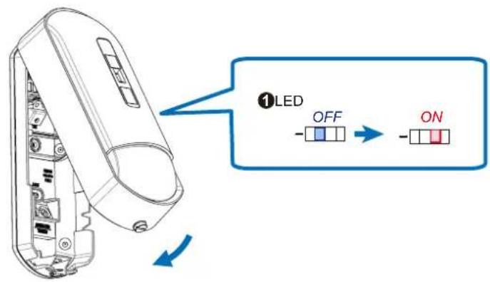
2 Walk in the detection area to check the detecting performance via LED indication.

natural_image
Diagram showing a person walking toward a device emitting light rays, with a line of parallel lines radiating outward (no text or symbols)3 Return the LED switch to "OFF" after the walk test, if necessary.

4 Lock the cover

NOTE
Conduct a walk test at least once a year.
- Specifications
| Models | FLX-A-AM | FLX-A-DAM-X5/-X8/-X9 | |
| Installation | |||
| Detection method | Passive infrared | Passive infrared and Microwave UL*** | |
| Coverage | Wide: 15 m (50 ft.) 85°, Narrow: 24 m (80 ft.) 5°(No MW detection at "Narrow" setting) | ||
| Detection zones | Wide: 80 zones/ Narrow: 20 zones | ||
| Mounting height | 2.0 to 3.0 m (6'7" to 9'8") | ||
| Alarm period | 2.0 ± 0.5 s | ||
| Warm-up period | Approx. 60 s (LED blinks) | ||
| LED indicator UL ** | Switchable ON/OFFMultiple: Warm-upGreen: Alarm and Masking detectionYellow: Self test errorRed: Low voltage | Switchable ON/OFFMultiple:Warm-upGreen:Alarm and Masking detectionPurple:PIR detectionYellow:Microwave detection and self test errorRed:Low voltage | |
| Electrical | |||
| Power input | 9.5 to 16 V DC UL* | ||
| Current draw | 12 mA (normal)16 mA (max.) at 12 V DC | 16 mA (normal)21 mA (max.) at 12 V DC | |
| Relay output | Trouble | N.C. 24 V DC 0.1 A max. (Resistive load) | |
| Alarm | N.C. 24 V DC 0.1 A max. (Resistive load) | ||
| Tamper | N.C. 24 V DC 0.1 A max. (Resistive load)(Open when the cover is removed.) | ||
| Remote LED | Terminal: open = OFF 0 V = ON | ||
| Environmental | |||
| Operation temperature | -20°C to +50°C(-4°F to +122°F) | -20°C to +45°C(-4°F to +113°F) | |
| Temperature compensation | Digital (SMDA) | ||
| Environmental humidity | 95% max. | ||
| RF interference | No alarm 10 V/m | ||
| Mechanical | |||
| Dimension | H: 159.1 x W: 62.2 x D: 55.7 mm (H: 6.26" x W: 2.45" x D: 2.19") | ||
| Weight | Approx. 180 g (6.35 oz) | Approx. 200 g (7.05 oz) | |
| Mounting | Wall, Corner (Indoor)(with Bracket : Wall, Corner, Ceiling) | ||
- Specifications and designs are subject to change without prior notice.
• These units are designed to detect an intruder and activate an alarm control panel. Being only a part of a complete system, we cannot accept responsibility for any damages or other consequences resulting from an intrusion.

* Shall be powered via a UL listed burglar alarm class 2 output power limited power supply that has a minimum standby power of 4 hrs.
** When DIP Switch 1 is turned off, all LED indications except Warm-up period are turned off. When DIP Switch 6 is turned off, LED indications for PIR and MW detections are turned off (Others, includes Self test error, stay ON).
*** When Microwave is enabled for UL compliance, it shall be set to high sensitivity. Setting to a lower sensitivity may impact and lessen range of the unit.
- Events and responses
| Events | Triggered by | Output & Remarks |
| Anti-masking detection | Objects close to the lens surface over 20 sec. | Alarm and Trouble signals. |
| Local self test | Controlled by detector's circuit periodically.(PIR and Microwave are tested at the same time.) | Fail; Trouble signal.(Detector doesn't work for about 10 seconds during local self test.) |
| Walk test | Conduct a walk test at least once a year. | Keep at least 1 meter from the detector and clear of any objects. |
| Low voltage detection | Voltage drop. | Trouble signal |
- LED indications

bar
| Event Type | Duration (s) | |----------------------|--------------| | Warm-up | Multiple, 60 s | | Masking detection | Green, Repeats | | Alarm | 2 s | | PIR detection | 2 s | | MW detection | 2 s | | Self test error | Yellow, Repeats | | Low voltage | Red, repeats |- Dimensions
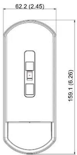

Unit: mm (inch)

- Detection area
Wide - Top view -

radar
| View | Value | |------|-------| | PIR | 0 | | MW Low | 20 | | MW Middle | 10 | | MW High | 8 |Wide - Side view -

line
| Depth (m) | Value | | --------- | ----- | | 0 | 0 | | 1 | 1 | | 2 | 2 | | 3 | 3 | | 4 | 4 | | 5 | 5 | | 6 | 6 | | 7 | 7 | | 8 | 8 | | 9 | 9 | | 10 | 10 | | 11 | 11 | | 12 | 12 | | 13 | 13 | | 14 | 14 | | 15 | 15 | | 16 | 16 | | 17 | 17 | | 18 | 18 | | 19 | 19 | | 20 | 20 | | 21 | 21 | | 22 | 22 | | 23 | 23 | | 24 | 24 | | 25 | 25 | | 26 | 26 | | 27 | 27 | | 28 | 28 | | 29 | 29 | | 30 | 30 | | 31 | 31 | | 32 | 32 | | 33 | 33 | | 34 | 34 | | 35 | 35 | | 36 | 36 | | 37 | 37 | | 38 | 38 | | 39 | 39 | | 40 | 40 | | 41 | 41 | | 42 | 42 | | 43 | 43 | | 44 | 44 | | 45 | 45 | | 46 | 46 | | 47 | 47 | | 48 | 48 | | 49 | 49 | | 50 | 50 |Narrow - Top view -

line
| Distance (m) | Value | | ------------ | ----- | | 0 | 0 | | 2 | 1 | | 4 | 0 | | 6 | 0 | | 8 | 0 | | 10 | 0 | | 12 | 0 | | 14 | 0 | | 16 | 0 | | 18 | 0 | | 20 | 0 | | 22 | 0 | | 24 | 0 |Narrow - Side view -
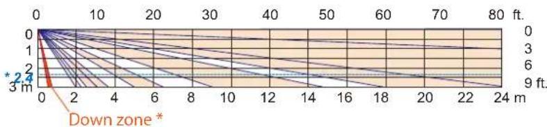
line
| Depth (m) | Value | | --------- | ----- | | 0 | 0 | | 1 | 1 | | 2 | 2 | | 3 | 3 | | 4 | 4 | | 5 | 5 | | 6 | 6 | | 7 | 7 | | 8 | 8 | | 9 | 9 | | 10 | 10 | | 11 | 11 | | 12 | 12 | | 13 | 13 | | 14 | 14 | | 15 | 15 | | 16 | 16 | | 17 | 17 | | 18 | 18 | | 19 | 19 | | 20 | 20 | | 21 | 21 | | 22 | 22 | | 23 | 23 | | 24 | 24 |NOTE
- The * 2.4 dotted line indicates the recommended mounting height.
- When "Narrow" is selected in the lens setting, MW detection will be stopped.
- Down zone * can be deleted by switch setting (See 2-4).
- Angle adjustment with bracket


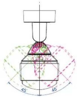
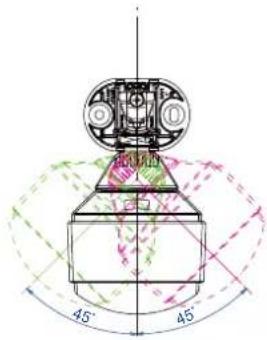
NOTE
* If the detector cover does not reach the ceiling, it can be swung up to +5°.
natural_image
Two side-view line drawings of a device with internal components, no text or symbols present.
natural_image
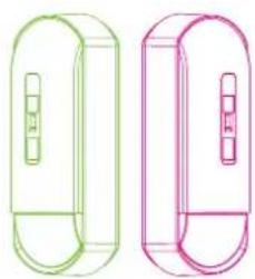
Two identical line drawings of a cylindrical device with internal components, shown in green and pink outlines (no text or symbols)- Compliance
RE Directive 2014/53/EU
■ Hereby, OPTEX declares that the radio equipment type FLX-A-DAM-X5, FLX-A-DAM-X8, and FLX-A-DAM-X9 are in compliance with Directive 2014/53/EU. The full text of the EU declaration of conformity is available at the following internet address: www.optex.net
■ Microwave emission Frequency and Power
FLX-A-DAM-X5: 10.525 GHz 15.78 mW e.i.r.p
FLX-A-DAM-X8: 10.587 GHz 8.93 mW e.i.r.p
FLX-A-DAM-X9: 9.425 GHz 14.50 mW e.i.r.p
■ The following list indicates the areas of intended use of the equipment and any known restrictions.
For countries not included in this list, please consult the responsible Spectrum Management Agency.
10.525 GHz: Belgium, Denmark, Finland, Germany, Greece, Italy, Luxembourg, The Netherlands, Spain, Sweden, Iceland, Norway, Switzerland
10.587 GHz: Belgium, France, Germany, Ireland, Luxembourg, The Netherlands, United Kingdom
9.425 GHz: Austria, Czechia, Estonia, Germany, Slovakia, Turkey, Russia
- FLX-A-DAM-X5, FLX-A-DAM-X8, and FLX-A-DAM-X9 also comply with EU radiation exposure limits set forth for an uncontrolled environment. This equipment should be installed and operated with minimum distance 20 cm between the radiator & your body.
UK Radio Equipment Regulations 2017
■ FLX-A-DAM-X8 also comply with UK radiation exposure limits set forth for an uncontrolled environment. This equipment should be installed and operated with minimum distance 20 cm between the radiator & your body.
■ Hereby, OPTEX declares that the radio equipment type FLX-A-DAM-X8 is in compliance with Radio Equipment Regulations 2017. The full text of the UK declaration of conformity is available at the following internet address: www.optex.net
■ EN 50131-1 Grades and Environmental Class; Security Grade 3, Environmental Class II Applied Standards; EN 50131-2-2 (FLX-A-AM), EN 50131-2-4 (FLX-A-DAM-X5 and FLX-A-DAM-X8) Tested and certified by Telefication
■ Iarm klass 3, miljö klass II, SSF 1014
PD6662:2017
■ UL/c-UL listed (FLX-A-AM and FLX-A-DAM-X5)
■ EU & UK contact information

https://navi.optex.net/cert/contact/

OPTEX
OPTEX CO., LTD. (JAPAN)
www.optex.net
OPTEX INC./AMERICAS HQ (U.S.) www.optexamerica.com
OPTEX (EUROPE) LTD./EMEA HQ (U.K.) www.oplex-europe.com
OPTEX SECURITY B.V. (The Netherlands) www.optex-europe.com/nl
OPTEX SECURITY SAS (France) www.optex-europe.com/fr
OPTEX SECURITY Sp.z o.o. (Poland) www.optex-europe.com/pl
OPTEX PINNACLE INDIA, PVT., LTD. (India) www.optexpinnacle.com
OPTEX KOREA CO.,LTD. (Korea) www.optexkorea.com
OPTEX (DONGGUAN) CO.,LTD. SHANGHAI OFFICE (China) www.optexchina.com
OPTEX (Thailand) CO., LTD. (Thailand) www.optex.co.th
Copyright (C) 2022 OPTEX CO.,LTD.
- Flexible Range Indoor Detector
- FlipX series
- ADVANCED MODELS
- Before installation
- - Manufacturer's statement
- - Anti-masking
- Overview of anti-masking
- Sensitivity setting
- Installation
- 1- 1. Disassemble
- Wire and mount on the wall
- Join the base on the bracket
- Fix the base with the fixing screws
- How to change the bracket to the ceiling mounting
- Wire and mount on the ceiling
- 1-5. Wiring
- Wire to the terminal block
- Attach the terminal block to the base
- Power cable length
- NOTE
- Settings
- 2-1. Wide/Narrow setting
- 2-3. EOL settings
- Checking
- 3-1. Walk test
- - Specifications
- - Events and responses
- - LED indications
- - Dimensions
- - Detection area
- - Angle adjustment with bracket
- - Compliance
- OPTEX
- OPTEX CO., LTD. (JAPAN)
Brand : OPTEX
Model : FlipX FLX-A-AM
Category : Uncategorized