
IFS16-M10-BT03 - Security Camera Illustra - Free user manual and instructions
Find the device manual for free IFS16-M10-BT03 Illustra in PDF.


| Type | Security Camera |
| Model | IFS16-M10-BT03 |
| Brand | Illustra |
| Dimensions | 200 mm x 70 mm x 70 mm (approx.) |
| Weight | 0.9 kg (approx.) |
| Power Supply | 12V DC or PoE (IEEE 802.3af) |
| Resolution | 1080p (1920 x 1080) at 30 fps |
| Lens | Fixed 2.8mm, F2.0 |
| Field of View | 100° (horizontal) |
| Night Vision | Up to 30 m with IR LEDs |
| Weatherproof | IP67 rated |
| Storage | MicroSD slot up to 128 GB |
| Connectivity | Ethernet RJ45, WiFi optional |
| Compression | H.265 / H.264 |
| Operating Temperature | -20°C to 50°C |
| Maintenance | Clean lens with soft cloth; check connections periodically |
| Safety | Overvoltage protection; stable wall mount required |
| Spare Parts | Mounting bracket, screws, power adapter (if not PoE) |
| Warranty | 2 years (subject to terms) |
Frequently Asked Questions - IFS16-M10-BT03 Illustra
User questions about IFS16-M10-BT03 Illustra
0 question about this device. Answer the ones you know or ask your own.
Ask a new question about this device
Download the instructions for your Security Camera in PDF format for free! Find your manual IFS16-M10-BT03 - Illustra and take your electronic device back in hand. On this page are published all the documents necessary for the use of your device. IFS16-M10-BT03 by Illustra.
USER MANUAL IFS16-M10-BT03 Illustra
- 1 x Torx wrench
• 1 x Quick Start Guide - 2 x Moisture absorbers and absorber guide
- 1 x Test monitor cable
- 1 x Waterproof cap and Gasket
Installation tools
- Torx wrench
- Screw driver
Note: The camera should only be installed by a qualified installer. No
user serviceable parts inside. Refer servicing to qualified personnel. Before you start or install, refer to and read all important 'Safety' related start of install, refer to and read all important's information provided in the year's manual at
omination provided in the user's manual https://illustracameras.com/cameras/
143/
Johnson
Controls

Camera Parts: Figure 1

Figure 1
Quick reference
- Default IP: 192.168.1.168 (DHCP enabled)
- Default Username / Password: admin / admin
• Note: When you first log into the camera you must change
the password. Click the 'Change Password' button and enter a new password as per the on screen password guidelines.
• Power: DC12V / PoE IEEE 802.3at PoE+
Camera sensor modules assembly
-
Use the Torx wrench to remove the four screws on the camera dome (Figure 1) and remove the dome from the camera base.
-
Take the four sensor modules out of their boxes and assemble them on to the sensor module block (Figure 2).
Note: First, align the sensor module block arrow guide with the base's arrow guide and gently press the sensor module into the base until it is completely seated.

Figure 2
Camera buttons
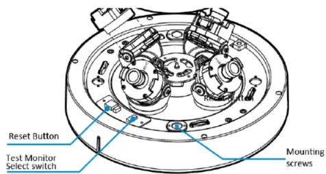
Figure 3
Reset Button: Pressing and holding the 'Reset' button for 5 seconds returns the camera to its factory default settings.
Test Monitor Cable Port and Video Select Switch: Connecting the Test Monitor Cable to this port and to a video monitor lets installers inspect and align each camera module. Use the 'Video Select Switch' to select the camera.
Camera Installation
First, attach a mounting plate or mounting arm to the surface that you want to attach the camera. See applicable mounts in the table below:
| Mount Product Code | Description on label |
| IBPN-M-IS12-0 | Flex Multi-sensor Ceiling bracket |
| IBWS-M-ISWB-0 | Flex Multi-sensor Wall bracket |
| IBCR-M-ISWT-0 | Flex Multi-sensor In-Ceiling bracket |
| IBJB-M-ISWB-0 | Flex Multi-sensor Junction bracket |
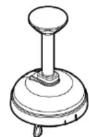
IBPN-M-IS12-0

IBWS-M-ISWB-0

IBCR-M-ISWT-0

IBJB-M-ISWB-0
Figure 4
Camera Installation (continued)
- To install a camera mount see the mounting Quick Start Guide at https://illustracameras.com/accessories/.
- Hold the camera base up to the mount and place all cables through the cable hole on the camera mount.
- Align the two metal pins on the top of the camera base with the two holes on the mount and rotate the camera base so that the camera base sits into the mount.
Note: The bridge on the camera base (Figure 5) aligns with the 'lock' and 'unlock' bridges on the mount.

Figure 5
- To securely attach the camera base to the mount you must insert the two mounting screws provided with the mount into the two holes on the camera base (Figure 3).
- Adjust the four camera modules (Figure 6) on to the four magnetics on the camera base to ensure the best view. Note: Align the four camera modules as per one of the three example shown in Figure 6.
Note: Ensure that the camera modules are level with the dome and that the base guide is resting flat on the magnetic track.
Camera Installation (continued)
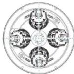


Figure 6
Note: Ensure that the camera module angle does not exceed 60 degrees. See Figure 7.

Figure 7
Camera Installation (continued)
- Use the Torx wrench to securely attach the dome cover to the camera base.
- Remove the outer protective film from the dome cover to complete the installation.
Camera cable port connections
See the camera cable port connections in Figure 8.

Figure 8
Figure 8: Camera cable port descriptions
- Power: Connect the DC12V power cable to the power cable port on the camera.
'OR' Network: Connect the camera's network cable to an 802.3at PoE+ switch. - Audio Output: Connect the audio output device cable to the 'Audio Output' camera cable port on the camera.
- Audio Input: Connect the audio input device cable to the 'Audio Input' camera cable port on the camera.
- Alarm Output: Connect the alarm output device cable to the blue and grey cables on the camera 'Alarm/Out' cable.
- Alarm Input: Connect the alarm input device cable to the yellow and white cables on the camera 'Alarm/In' cable.
Web GUI
Note: Use IE10 (or above) or Chrome to access the camera web GUI. See the web GUI screen layout in Figure 9 and their descriptions below.
Web GUI (continued)

Figure 9
- Live video display – This is the cameras live video stream.
- Setup button – Provides access to the configuration GUI.
(E.g. Video/Network/Events/Records/Security Configurations). - Select Viewer – Select individual video streams or Quad (VLC plug-in only).
- Live Viewer – Select one option: VLC plug-in or HTML (MJPEG). See Figure 10.
Web GUI (continued)
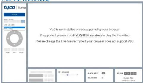
Figure 10
- Channel Select button – VLC Plug-in only: Selects one of three camera streams for web GUI display. Note: Each sensor supports up to three streams.
-
Camera Controls:
-
PTZ Control / Preset – Not supported in web GUI.
-
Speaker Control and MIC – Supported.
• Alarm Input / Relay Out - Supported. -
Motion – Motion Detection indicator
- Camera Time - Displays the camera time.
Warnings
- This product is intended for professional installation, please follow local wiring regulations.
- Do not install where children are likely to have access.
- Be sure to use only the standard adapter that is specified in the specification sheet. Using any other adapter could cause fire, electrical shock, or damage to the product.
- Incorrectly connecting the power supply or replacing battery may cause explosion, fire, electric shock, or damage to the product.
- Do not connect multiple cameras to a single adapter. Exceeding the capacity may cause abnormal heat generation or fire.
- Securely plug the power cord into the power receptacle. Insecure connection may cause fire.
- When installing the camera, fasten it securely and firmly.
- Do not place conductive objects (e.g. screw drivers, coins, metal things, etc.) or containers filled with water on top of the camera. Doing so may cause personal injury due to fire, electric shock, or falling objects.
- To prevent damage which may result in fire or electric shock hazard, do not expose this appliance to rain or moisture.
© 2020 Johnson Controls. All rights reserved.
JOHNSON CONTROLS, TYCO and ILLUSTRA are trademarks and/or registered trademarks. Unauthorized use is strictly prohibited.
Brand : Illustra
Model : IFS16-M10-BT03
Category : Security Camera