
IPS02-B12-OI03 - Security Camera Illustra - Free user manual and instructions
Find the device manual for free IPS02-B12-OI03 Illustra in PDF.


| Product Type | Outdoor Bullet Security Camera |
| Image Sensor | 1/2.8" Progressive CMOS (typical) |
| Resolution | Up to 2MP (1080p) (typical) |
| Lens | Varifocal, with automated calibration via web GUI |
| Power Supply | 24 VAC (1.27A min) or PoE+ IEEE 802.3at Class 4 (48VDC, 0.38A min) |
| Network Interface | RJ45 10/100Base-T with PoE+ |
| Video Output | BNC analog (NTSC/PAL) for service |
| Audio | Line in / Line out via terminal block |
| Alarm | 2 inputs, 1 output (terminal block) |
| Storage | Micro SD card slot (local recording) |
| Default IP Address | 192.168.1.168 (DHCP enabled) |
| Default Credentials | Username: admin, Password: admin |
| Reset Button | Hold for 20 seconds to restore defaults |
| Mounting Options | Surface (with mounting arm), pendant/pole (1.5" NPT adaptor included) |
| Sun Shield | Adjustable, removable for inverted mounting |
| Operating Temperature | -40°C to 60°C (typical outdoor) |
| Ingress Protection | IP66 (typical for outdoor bullet cameras) |
| Dimensions (Camera Body) | Approx. 8" x 4" x 4" (typical) |
| Weight (Camera Only) | Approx. 2.5 lbs (1.1 kg) |
| Included Accessories | Mounting arm, templates, screws, T10 wrench, Allen key, desiccant bag, rubber plugs |
| Regulatory | NRTL listed power adaptor required for US/Canada, outdoor use at least 3m above ground |
Frequently Asked Questions - IPS02-B12-OI03 Illustra
User questions about IPS02-B12-OI03 Illustra
0 question about this device. Answer the ones you know or ask your own.
Ask a new question about this device
Download the instructions for your Security Camera in PDF format for free! Find your manual IPS02-B12-OI03 - Illustra and take your electronic device back in hand. On this page are published all the documents necessary for the use of your device. IPS02-B12-OI03 by Illustra.
USER MANUAL IPS02-B12-OI03 Illustra
- 4 x plastic screw anchors (use on masonry walls and wood)
- 4 x Phillips pan head tapered screw TP6x32mm (use on masonry wall and wood)
- 4 x Phillips pan head tapered screw M5x8mm (Adaptor plate base)
- 1 x Printed Quick Start Guide
• 1 x Printed regulatory document - 1 x NTSC / PAL output female BNC cable
- 1 x RJ45 Connector
- 1x RJ45 Connector
- 1 x Terminal block
- 1 x Terminal block
- 1 x Mounting arm
- 1 x Mounting arm
- 1 x Mounting tem
- 1 x Mounting template
- 1 x Desiccant bag
- 1 x Desiccant bag
- 4 x Toggle screw (Expansion Bolt)
- 4 x Toggle screw (Expansion
- 1 x T10 security Torx wrench
- 1 x Universal electrical box mounting plate (IPSMDEBPLATE)
• 1 x Pendant / pole mount adaptor - 1 x rubber plug (with two holes) and 1 rubber pin
- 1 x rubber plug (with no holes)
- 1 x 4mm Allen key
Installation tools - 1 x Drill
• 1 x T10 security Torx wrench
• 1 x Phillips screw driver

Quick reference
- Default IP: 192.168.1.168 (DHCP enabled)
- Default Username and Password: admin
Note: You can attach the camera to a surface or directly to a pendant or pole 1 12 " Male NPT pipe using the pendant / pole mount adaptor. (The pendant / pole mount adaptor can be attached to a standard 1 12 " NTP pipe using threads or set screws). Note: To ensure optimal lens performance, JCI recommends using the automated lens calibration feature within the web GUI following initial camera installation.
- Attaching the mounting arm to a surface
A. Place the mounting template provided on the surface and drill four 8mm (0.314inch) holes.
B. Insert the four screw anchors into the four holes on the surface.
C. After passing all required cabling through the mounting arm, place the mounting arm (1) (Figure 1) on the surface and align the four holes on the mounting arm (2) (Figure 1) with the four screw anchors or expansion bolts on the surface (3) (Figure 1).
D. Insert the rubber plug into the top hole on the mounting arm (4) (Figure 1) to prevent water from entering the mounting arm.

Figure 1
- Attaching the mounting arm to a surface (continued)
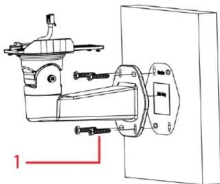
E. Securely attach the mounting arm to the surface with the four TP6x32mm screws (1) (Figure 2).
natural_image
Technical line drawing of a mechanical device with no visible text or symbolsFigure 2
F. Insert the Ethernet cable through the waterproof rubber (1) (Figure 3) and if not using both grommet holes insert the rubber pin (2) (Figure 3) into the waterproof rubber.
G. Insert the waterproof rubber onto the mounting arm plate. (3) (Figure 3).
- Attaching the mounting arm to a surface (continued)
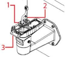
Figure 3
- Attaching the camera to the mounting arm
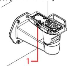
A. Push the pin (1) (Figure. 4) from the mounting arm hinge.
natural_image
Technical line drawing of a mechanical housing component with mounting flanges and internal components (no text or symbols)Figure 4
- Attaching the camera to the mounting arm (continued)
B. Place the camera onto the hinge (1) (Figure 5) and release the pin so that the camera is attached to the mounting arm plate.

natural_image
Technical line drawing of a mechanical device with internal components and a red annotation line (no text or symbols)Figure 5
C. See step 4 to connect the power cable and then continue on at step D.
D. Flip the camera so that it sits properly on the mounting arm plate and secure it to the mounting arm plate with the four T10 screws (1) (Figure 6).
- Attaching the camera to the mounting arm (continued)

Figure 6
- Attaching the camera to a pendant or pole 1 12 " NTP pipe
A. Place the pendant/pole mount adaptor (1) (Figure 7) around a standard 1 12 " Male NPT threaded water pipe (2) (Figure 7) and securely attach the two M3x0.5P (L = 6mm) screws on the pendant mount adaptor with the T10 security Torx wrench.

Figure 7
- Attaching the camera to a pendant or pole 1 12 “NTP pipe (continued)
B. Unscrew the M5 Hex socket cap screw (1) (Figure 8) to remove the mounting arm plate (2) (Figure 8) from the mounting arm (3) (Figure 8).

Figure 8
C. Push the pin (1) (Figure 9) and place the camera onto the hinge and release the pin so that the camera is attached to the mounting arm plate.

natural_image
Technical line drawing of a mechanical device with internal components and a red annotation arrow (no text or symbols)Figure 9
- Attaching the camera to a pendant or pole 1 ½ " NTP pipe (continued)
D. See step 4 to connect the power cable and then continue on at step E.
E. Securely attach the mounting arm plate to the camera with the four T10 screws (1) (Figure 10) on the mounting arm plate.
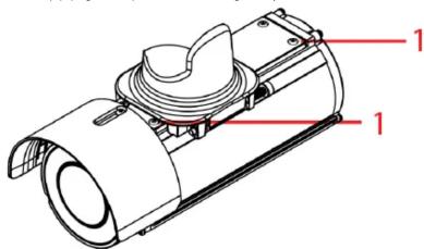
Figure 10
F. Place the mounting plate arm and camera into the pendant mount adaptor (1) (Figure 11) and securely attach the two M3x0.5P (L = 6mm) screws with the T10 security Torx wrench.
- Attaching the camera to a pendant or pole 1 12 " NTP pipe (continued)

Figure 11
- Connecting the power cable to the power plugs
A. Connect the power cable to the power plugs with one of the following options:
- AC 24V: Connect 24V cables to terminals AC 24V. - PoE+: Connect the RJ45 jack to a PoE compatible network device that supplies power through the Ethernet cable.
- Adjusting the camera position
A. Use the T10 security Torx wrench to adjust the bracket Tilt angle (2) (Figure 6) and to adjust the bracket Pan angle (3) (Figure 6).
- Adjusting the sun shield hood
A. Move the sun shield hood (4) (Figure 6) forward and backward to adjust the position of the sunshade.
Note: When the camera is mounted inverted to a pendant 1 ½" NTP pipe you must remove the sun shield hood by unscrewing the M3x0.5P (L = 8mm) screw with the T10 security Torx wrench (3) (Figure 11) and relocate the sun shield with screw as per the sun shield hood located in Figure 11.
CAUTION: Extending the sun shield hood forward could obstruct the field of view (FOV) when the camera lens is set to 'Wide'.
- Location of camera buttons, connections and Desiccant bag
Note: The figure below indicates the location of the camera buttons and connections (1) (Figure 12) and Desiccant bag (2) (Figure 12) on the camera.

Figure 12
Table 1: Camera buttons / connections
| Button / connections | Description |
| Alarm in 1 | |
| Alarm in 2 | |
| Alarm out | |
| COM | |
| Audio line in | |
| Audio line out | |
| Ground | |
| Analog out cable connection | |
| Micro SD card slot | |
| AC 24 V | AC power connection |
| USB cable connection | |
| Reboot button (Hold for 10 seconds) | |
| Reset button (Hold for 20 seconds) | |
| RJ45 Ethernet cable connection / PoE+ |
Table 2: Universal Mounting plate symbols and descriptions
| Plate Symbol | Name | Description |
| 4 | 4S Junction Box | Attach the plate to a North American 4 inch square electrical box. |
| O | Octagon Box | Attach the plate to a North American octagon electrical box. |
| U | Electrical box (UK) | Attach the plate to a UK electrical box. |
| E | Electrical box (EU) | Attach the plate to a European electrical box. |
Warnings
- For US and Canada use a NRTL listed power adaptor.
- The mains power adaptor equipment should be marked LPS (Limited Current Source) or PS2 and rated according to 50C, 24VAC, 1.27A min or PoE IEEE802.3at type 2 Class 4, 48VDC, 0.38A min.
- To meet security immunity requirements use an uninterruptable PSU to supply power to the mains adaptor or POE mid/end span.
- The cables for 24Vac, Audio and Alarms should not exceed 3m unless additional measures are taken to reduce the effect of interference picked up on the cables.
- USB and Analogue Video out cables should only be used temporarily for service and not permanently installed.
- For outdoor use the camera should be mounted at least 3m above ground level"
© 2019 Johnson Controls. All rights reserved.
JOHNSON CONTROLS, TYCO and ILLUSTRA are trademarks and/or registered trademarks. Unauthorized use is strictly prohibited.
Brand : Illustra
Model : IPS02-B12-OI03
Category : Security Camera