
RS-DC10 - Cassette player TECHNICS - Free user manual and instructions
Find the device manual for free RS-DC10 TECHNICS in PDF.


| Product Type | Digital Compact Cassette (DCC) Deck |
| Brand | Technics |
| Model | RS-DC10 |
| Dimensions (W x H x D) | 430 x 153 x 341 mm |
| Weight | 8.3 kg |
| Power Supply | AC 50/60 Hz; 240 V (UK), 230 V (Europe), 110/120/220/240 V (others) |
| Power Consumption | 35 W |
| Recording/Playback Formats | DCC digital recording and playback, analog cassette tape playback only |
| Sampling Frequencies | 48 kHz, 44.1 kHz, 32 kHz (auto select) |
| Frequency Response (DCC) | 10 Hz - 20 kHz (±0.2 dB) at 48 kHz |
| Signal-to-Noise Ratio (DCC playback) | 98 dB or more (A-weighted) |
| Wow and Flutter (DCC) | Below measurable limit |
| Analog Cassette Frequency Response | 30 Hz - 17 kHz (Metal tape, Dolby NR off) |
| Inputs | Analog (RCA), Digital coaxial (RCA) and optical (TOSLINK) |
| Outputs | Analog fixed (FIX) and variable (VARIABLE), digital coaxial + optical, headphone (6.3 mm) |
| Headphone Output Power | 30 mW + 30 mW (32 Ω load) |
| Supplied Accessories | Stereo connection cables (x2), remote control, batteries (x2), DCC recording tape, power plug adaptor (some regions) |
| Special Features | Auto reverse, Dolby B/C NR, skip search, title search, repeat play, timer playback/recording, marker editing |
| Maintenance | Clean head section with Technics cleaning tape; do not use demagnetizer |
| Repairability | No user-serviceable parts; contact dealer or authorized service center |
Frequently Asked Questions - RS-DC10 TECHNICS
User questions about RS-DC10 TECHNICS
0 question about this device. Answer the ones you know or ask your own.
Ask a new question about this device
Download the instructions for your Cassette player in PDF format for free! Find your manual RS-DC10 - TECHNICS and take your electronic device back in hand. On this page are published all the documents necessary for the use of your device. RS-DC10 by TECHNICS.
USER MANUAL RS-DC10 TECHNICS
DIGITAL COMPACT CASSETTE DECK
RS-DC10
Operating Instructions

Notes:
- Specifications differ according to the area code.
- The "EB" area code, for example, indicates United Kingdom specifications.
- The "EB" indication is shown on the packing case and serial number tag.
Before operating this unit, please read these instructions completely.
Features
Dear Stereo Fan
We thank you for selecting this product and welcome you to the growing family of satisfied Technics product owners around the world.
We feel certain you will get maximum enjoyment from this new addition to your home. Please read these operating instructions carefully, and be sure to keep them handy for convenient reference.
The DCC system comes with the features outlined below.
1. High-quality digital sound
Tape hiss, wow and flutter, distortion and other such problems have, in principle, been eliminated so that the deck can record and play back material with high sound quality virtually on a par with that of CDs.
2. Compatible with conventional analog cassette tapes
The deck can play back even cassette tapes which have been recorded using currently available analog input signals. This means that you can make full use of all the music cassette tapes in your possession.
3. Digital technology providing a touch of sophistication and greater convenience
The name of the album, names of the tracks and other character information can be displayed for prerecorded DCC music tapes.
4. More enjoyment and fun from listening to music
A fresh and original design with plenty of space for the labels has been adopted for DCC tapes. They can be removed from their cases with just a flip of the fingers.
The cassette tapes have virtually the same dimensions as conventional tapes, and they are extremely easy to handle.
This deck will play back both analog cassette tapes and digital compact cassette tapes. To record material, use DCC tapes only for recording.
Terms used in this manual
In order to make a clear distinction between the conventional cassette tapes (compact cassette tapes) and DCC tapes (digital compact cassette tapes), the former tapes are referred to in this manual as "analog cassettes" or "analog cassette tapes."
Always be sure to use the optional cleaning tape to clean the deck's head section.
Do not use a demagnetizer.
Under no circumstances must a demagnetizer for analog cassette decks be used since it may damage the head section.
Caution for AC mains lead
(For United Kingdom)
("EB" area code model only)
For your safety, please read the following text carefully.
This appliance is supplied with a moulded three pin mains plug for your safety and convenience.
A 5-ampere fuse is fitted in this plug.
Should the fuse need to be replaced please ensure that the replacement fuse has a rating of 5-ampere and that it is approved by ASTA or BSI to BS1362.
Check for the ASTA mark 📂 or the BSI mark 🌐 on the body of the fuse.
If the plug contains a removable fuse cover you must ensure that it is refitted when the fuse is replaced.
If you lose the fuse cover the plug must not be used, until a replacement cover is obtained.
A replacement fuse cover can be purchased from your local dealer.
CAUTION!
IF THE FITTED MOULDED PLUG IS UNSUITABLE FOR THE SOCKET OUTLET IN YOUR HOME THEN THE FUSE SHOULD BE REMOVED AND THE PLUG CUT OFF AND DISPOSED OF SAFELY. THERE IS A DANGER OF SEVERE ELECTRICAL SHOCK IF THE CUT OFF PLUG IS INSERTED INTO ANY 13-AMPERE SOCKET.
If a new plug is to be fitted please observe the wiring code as shown below.
If in any doubt please consult a qualified electrician.
IMPORTANT
The wires in this mains lead are coloured in accordance with the following code:
Blue: Neutral
Brown: Live
As the colours of the wires in the mains lead of this appliance may not correspond with the coloured markings Identifying the terminals in your plug, proceed as follows:
The wire which is coloured BLUE must be connected to the terminal in the plug which is marked with the letter N or coloured BLACK.
The wire which is coloured BROWN must be connected to the terminal in the plug which is marked with the letter L or coloured RED.
Under no circumstances should either of these wires be connected to the earth terminal of the three pin plug marked with the letter E or the Earth Symbol ⊥.
Before use
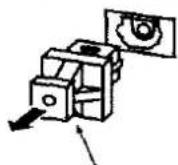
Remove the connector cover as follows.
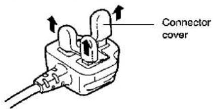
How to replace the fuse
- Remove the fuse cover with a screwdriver.
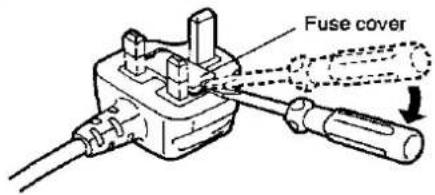
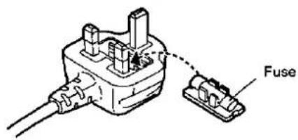
- Replace the fuse and attach the fuse cover.
Suggestions for Safety
■ Use a standard AC wall outlet
- Use from an AC power source of high voltage, such as that used for an air conditioner, is very dangerous.
A fire might be caused by such a connection.
- A DC power source cannot be used.
Be sure to check the power source carefully, especially on a ship or other place where DC is used.
■ Grasp the plug when disconnecting the power supply cord
- Wet hands are dangerous.
A dangerous electric shock may result if the plug is touched by wet hands.
- Never place heavy items on top of the power supply cord, nor force it to bend sharply.
■ Place the unit where it will be well ventilated
Place this unit at least 10 cm (4") away from wall surfaces, etc.
Be careful that curtains and similar materials do not obstruct the ventilation holes.
■ Avoid places such as the following: In direct sunlight or in other places where the temperature is high.
In places where there is excessive vibration or humidity.
Such conditions might damage the cabinet and/or other component parts and thereby shorten the unit's service life.
■ Be sure to place the unit on a flat, level surface.
If the surface is inclined, a malfunction may result.
■ Never attempt to repair nor reconstruct this unit
A serious electric shock might occur if this unit is repaired, disassembled or reconstructed by unauthorized persons, or if the internal parts are accidentally touched.
■ Take particular care if children are present
Never permit children to put anything, especially metal, inside this unit. A serious electric shock or malfunction could occur if articles such as coins, needles, screwdrivers, etc. are inserted through the ventilation holes, etc. of this unit.
■ if water is spilled on the unit
Be extremely careful if water is spilled on the unit, because a fire or serious electric shock might occur. Immediately disconnect the power cord plug, and consult with your dealer.
■ Avoid spray-type insecticides
Insecticides might cause cracks or "cloudiness" in the cabinet and plastic parts of this unit. The gas used in such sprays might, moreover, be ignited suddenly.
■ Never use alcohol or paint thinner
These and similar chemicals should never be used, because they might cause flaking or cloudiness of the cabinet finish.
■ Disconnect the power supply cord if the unit will not be used for a long time
If the unit is left for a long time with the power ON, this not only will shorten its useful operation life, but also may cause other trouble.
■ If trouble occurs
If, during operation, the sound is interrupted or indicators no longer illuminate, or if an abnormal odour or smoke is detected, immediately disconnect the power cord plug, and contact with your dealer or an Authorized Service Center.
Supplied Accessories

Before proceeding to install and connect the deck, be sure to check that all the supplied accessories are present and accounted for.
□ Stereo connection cables (×2)

☐ Remote control transmitter (DC10/EURZK011D002)

□ Batteries for remote controller (×2)
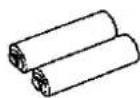
☐ DCC tape for recording (×1)

Power plug adaptor (×1) (For areas except Continental Europe, United Kingdom and Australia)

Before Use
(For areas except Continental Europe, United Kingdom and Australia)
Be sure to disconnect the mains cord before adjusting the voltage selector.
Use a minus (−) screwdriver to set the voltage selector (on the rear panel) to the voltage setting for the area in which the unit will be used.
(If the power supply in your area is 117 V or 120 V, set to the "127 V" position.)
Note that this unit will be seriously damaged if this setting is not made correctly. (There is no voltage selector for some countries; the correct voltage is already set.)
Note:
The configuration of AC power supply cord differs according to area.
(For areas except Continental Europe, United Kingdom and Australia)
If the power plug will not fit your Household AC outlet, use the power plug adaptor (included).

natural_image
Diagram showing a plug with two leads and a connector to an output plug (no text or symbols)
Table of Contents
| Preparations |
| Connections | 8 |
| Digital connections | 8 |
| Analog connections | 9 |
| DCC Tapes | 10 |
| Front Panel Controls and Functions | 12 |
| Control section | 12 |
| Display section | 13 |
| Concerning the Remote Control | 15 |
| DCC Tape Playback |
| DCC Tape Playback | 16 |
| What Appears on the Display | 18 |
| Counter display | 18 |
| Text information display | 19 |
| Handy Playback Functions Provided by the Deck | 21 |
| Changing the tape run direction (reverse function) | 21 |
| Rewinding and fast forwarding the tape | 21 |
| Skipping to a particular track (skip play) | 22 |
| Listening again from the start of a track now being played (replay function) | 23 |
| Selecting tracks by their titles (title search) | 23 |
| Playing back a track or tape repeatedly (repeat play) | 23 |
| Analog Cassette Tape Playback |
| Handy Playback Functions Provided by Remote Controller | 24 |
| Starting playback from a particular track number (direct playback) | 24 |
| Playing back the intros of tracks (music scan) | 25 |
| Adjusting the output level | 25 |
| Recording(DCC Only) |
| Analog Cassette Tape Playback | 26 |
| Setting the Dolby NR system | 27 |
| Changing the tape run direction (reverse function) | 28 |
| Rewinding or fast forwarding the tape | 28 |
| Finding the start of tracks (TPS function) | 28 |
| Listening again from the start of the track now being played (replay function) | 28 |
| Playing back the tape repeatedly (repeat play) | 29 |
| Quick reverse function | 29 |
| Concerning analog cassette tapes | 29 |
| Digital Input Recording | 30 |
| Recording from the start of a tape | 30 |
| Writing the track numbers | 32 |
| Precautions for digital input recording | 33 |
| Analog Input Recording | 34 |
| Recording from the start of a tape | 34 |
| Adjusting the recording level | 36 |
| Precautions for analog input recording | 36 |
Recording
(DCC Only)
Marker Editing
(DCC Only)
Timer Operations
(Common)
Remote Control Operations
(Common)
Useful Information
Technical Details
Various Recording Methods .... 37
Creating the unrecorded blanks 37
Recording from midway through a tape (append recording) 38
Types of Sub Codes for Editing and Their Functions 40
Start markers and track numbers 40
Editing of start markers and track numbers ..... 41
Markers for editing 42
Absolute time and append recording ..... 42
Time display 43
Marker Editing while Recording is in Progress 44
Changing the tape side to record (reverse marker) 44
Recording continuously on both sides of the tape (next marker) 46
Marker Editing after Recording 48
Writing the start marker manually 48
Erasing the written markers 49
Adding running numbers to the edited start markers (renumbering) 50
Timer Playback/Recording 52
Timer playback 52
Timer recording 53
Quick Reference Table of Remote Control Operations 54
Common operations 54
Playback 54
Recording 55
Editing 55
Troubleshooting Guide 56
Maintenance Procedures 58
Technical Specifications .... 59
SCMS (Serial Copy Management System) .... 60
Connections
Be sure to turn off the power to all the components before proceeding to connect them. Connect the power cable only after all the other connections have been performed.
An example of the connections is given below. For further details, consult the Operating Instructions of the components involved as well.
Digital connections
There are two ways to perform the digital connections: either connect a digital amplifier to the deck or connect another digital component directly to the deck.

Digital direct recording
A CD player or other digital component can be connected directly to the deck and the digital signals of that component can be recorded without further ado. (See "SCMS" on pages 60 and 61.)
About Optical Fiber Cables
To connect optical fiber cables
① Remove the dust cap from the terminal. ② Connect the cable.
Dust cap

Align the terminal shape.
Do not attempt to bend optical fiber cables at severe angles.
Be sure that connections are made securely.
Store the dust cap securely, and replace it whenever cables are not connected to the terminals. If dust is allowed to enter the terminal connector, signal errors may result.
About OPTICAL connector
When the optical connectors are used, electrical signals are converted into light signals for transmission between units, making the signals impervious to adverse effects from external noise. This form of connection thus allows the highest quality of digital audio signal transmission.
Analog connections

Connections to deck's analog output connectors
This deck comes with two pairs of analog output connectors. Use the accessory stereo connection cable to connect a unit to one of these two pairs of connectors.
Fixed output connectors (FIX)
Normally, these output connectors are used. When a unit has been connected to them, the output level cannot be adjusted by operating the accessory remote controller.
Variable output connectors (VARIABLE)
Use these connectors when the output level is to be adjusted using the accessory remote controller.
Installation
Avoid locations nearby tuners or television sets.
Since this unit uses high-frequency signals, placing it near a tuner or television set may result in interference with the tuner/TV reception. If this kind of audio or video interference is experienced, move the DCC unit away from other AV components.

Since the same kind of phenomenon may occur when an indoor antenna is used with the tuner or TV set, use an outdoor antenna instead.
Types of tapes which can be used
The types of tapes described below can be used with this deck.
Digital compact cassette tapes (DCC)
There are two types of DCC tapes.
-
Prerecorded DCC music tapes available in stores: For playback only
-
DCC tapes for recording
Conventional analog cassette tapes: For playback only (Analog compact cassette tapes)
DCC tapes for recording

Unlike analog cassette tapes, DCC tapes are completely sealed, and their tape and hub holes are protected by a slider.
This design ensures that, except when the cassette is loaded, dust and foreign particles will not enter the cassette housing and cause dropouts (digital signal losses) which are the main cause of deterioration in the quality of digital recordings.
DCC tapes for recording come in lengths of 45, 60 and 90 minutes.
Tampering with the cassette tape length identification holes in any way can cause malfunctioning.
Safeguarding against the accidental erasure of a valuable recording

Recorded tapes that you want to keep can be protected by sliding the accidental erasure prevention tab on the rear side of the cassette to the "up" position shown in the diagram. It will then be impossible to record on the tape, thus protecting important recordings from accidental erasure.
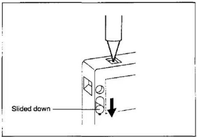
To re-record
Return the accidental erasure prevention tab to its indented (open) position.
Handling precautions
Do not open the cassette's slider to pull the tape out or touch it.
Take care not to drop the cassette, hit it or subject it to strong vibration.
The cassette cannot be turned over and used.
Storage precautions
Replace the cassette in its case and store away.
Do not place or store tapes in the following places:
-
Where it is very hot (over 35°C) or very humid (over 80%)
-
Where there are strong magnetic fields (near speakers or on top of a TV set, etc.)
- Where the tapes will be exposed to direct sunlight
Front Panel Controls and Functions
Control section

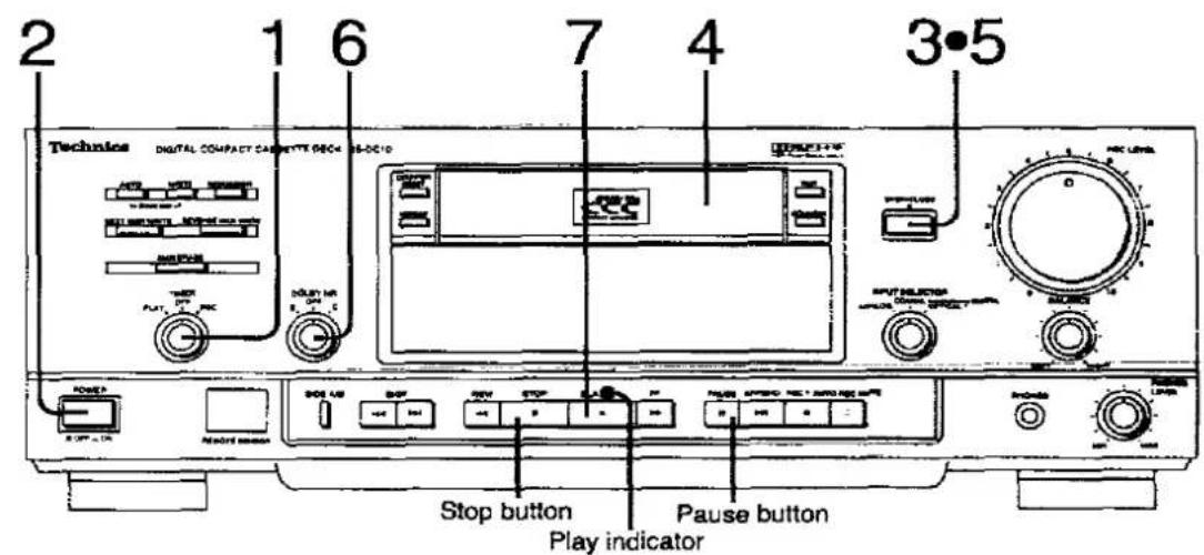
① Power switch (POWER)
② Timer switch (TIMER)
Use this when a timer from an audio store has been connected to start playback or recording at a particular time. (See pages 52–53.)
③ Marker control section AUTO START MKR:
For setting the start marker's writing mode to automatic or manual. (See pages 32 and 41.)
START MKR WRITE:
For writing the start marker manually. (See pages 41 and 48.)
RENUMBER:
For renumbering the track sequence when correcting the track numbers. (See pages 41, 50 and 51.)
NEXT MKR WRITE:
For writing the next marker which automatically activates playback from the start of the reverse side. (See pages 42 and 47.)
REVERSE MKR WRITE:
For writing the reverse marker which automatically reverses the tape side from A to B.
(See pages 42 and 45.)
MKR ERASE:
For erasing written markers. (See pages 41 and 49.)
④ Dolby NR selector (DOLBY NR)
This can be set to Dolby B. C or OFF, depending on which Dolby position, if any, was used for the recording on the analog cassette tape which is to be played back. (See page 27.)
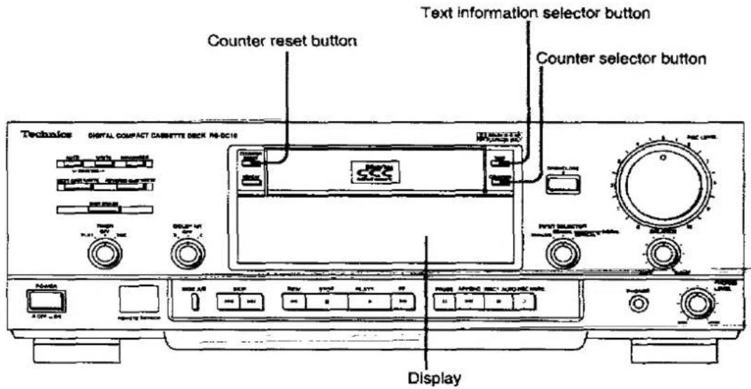
⑤ Counter reset button (COUNTER RESET)
Use this to return the tape counter to "0000".
⑥ Repeat mode selector button (REPEAT)
Use this to switch to the repeat play mode. (See pages 23 and 29.)
⑦ Display section
(See pages 13-14 for details.)
⑧ Cassette tray
⑨ Text Information selector button (TEXT)
Use this to select what is to be displayed—the title of the track now being played, etc. (See page 19.)
⑩ Counter selector button (COUNTER)
Use this to select the tape counter's display mode. (See page 18.)
⑪ Cassette tray open/close button (OPEN/CLOSE ▲)
Use this to open or close the cassette tray.
⑫ Input selector (INPUT SELECTOR)
Use this to select the analog (ANALOG)/digital input (COAXIAL/OPTICAL). (See pages 30 and 34.)
⑬ Recording level control (REC LEVEL)
Use this to adjust the recording level when analog input signals are being recorded. (See pages 35–36.)
⑭ Balance control (BALANCE)
Use this to adjust the balance between the left and right channels when analog input signals are being recorded. (See pages 35–36.)
⑮ Remote control sensor (REMOTE SENSOR)
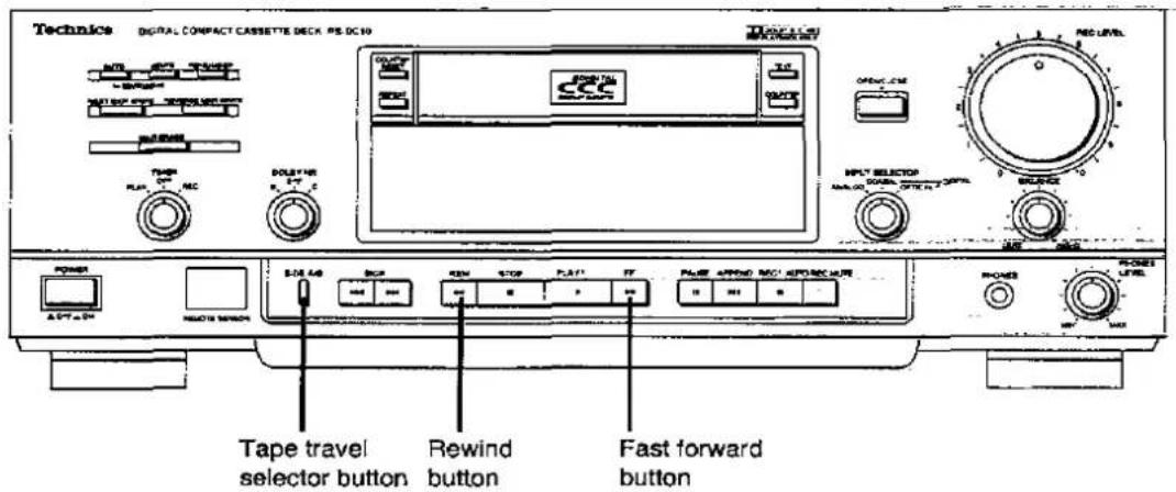
⑯ Tape travel selector button (SIDE A/B)
Use this to select the direction in which the tape is to travel. (See pages 21 and 28.)
⑰ Skip buttons (SKIP|◀◀/▶▶I)
Use these to skip to the track you want to hear.
(See pages 22 and 28.)
⑱ Basic control section
Rewind button (REW ◀◀◀)
Stop button (STOP ■)
Play button and indicator (PLAY ▶)
Fast forward button (FF ▶▶)
⑲ Pause button (PAUSE III)
20 Append recording button (APPEND▶II)
Use this to search for the end of the recorded section on the tape where more material is to be appended, and set the deck to the recording standby mode. (See pages 38–39.)
② Record button and indicator (REC ●)
② Auto rec mute button (AUTO REC MUTE O)
Use this to create unrecorded blanks between tracks on the tape. (See page 37.)
②3 Headphones jack (PHONES)
②4 Headphone volume control (PHONES LEVEL)
Display section

1 Tape travel direction indicators
(◀ B / A ▶)
These indicate the direction in which the tape is traveling.
(The B / A display appears only when a DCC tape is used.) (See pages 21 and 28.)
② Reverse mode indicator
This indicates the reverse mode.
(For analog cassette tapes only) (See page 29.)
③ Dolby NR indicators (DOLBY B C)
These indicate the type of Dolby noise reduction which has been selected. When both of these indicators are off, it means that neither type of Dolby noise reduction has been selected. (See page 26.)
4 Repeat mode indicators
(CONT REPEAT/REPEAT TRACK)
CONT REPEAT:
All tracks are repeated. (See pages 23 and 29.)
REPEAT TRACK:
The track being played is repeated.
(For DCC tapes only) (See page 23.)
Level meters
These indicate the input levels during recording and the levels recorded on the tape during playback.
When a DCC tape is used, the values at the top are displayed; when an analog cassette is used, the values at the bottom are displayed. (See page 36.)

⑥ Text information/counter display section
When a prerecorded DCC music tape is played back, text information relating to what is being played appears on the display. (See pages 18–20.)
Track number display (TRACK):
This indicates the number of the track which is being played back or recorded.
Timer/counter display (TIME/COUNTER):
This indicates how many minutes and seconds of the track which is being played back or recorded have elapsed or it shows the tape counter display.
Mode display (MODE):
This indicates the operating mode which is currently established.
⑦ Marker indicator section
Start marker auto write Indicator ( AUTO ):
This lights when the start marker is set to the automatic writing mode. (See page 32.)
Start marker indicator (START):
This lights when the start marker has been written manually or when the start marker position is reached. (See pages 48–49.)
Reverse marker Indicator (REVERSE):
This lights when the reverse marker has been written or when the reverse marker position is reached.
(See page 45.)
Marker indicator (MARKER):
This lights when any of the marker positions is reached. (See page 49.)
Marker write indicator (WRITE):
This lights while a marker is being written.
Marker erase Indicator (ERASE):
This lights while a marker is being erased.
(See page 49.)
8 DCC indicator ( dcc )
This lights only when a DCC tape is being used.
Counter display indicators
(ABS, REM, TOTAL, THACK)
The indicator corresponding to the setting of the COUNTER selector button is selected as follows. (See pages 18-19.)
ABS
: Absolute time display (See page 18.)
REM
: Time remaining on one side of the tape
REM
: Total time remaining on the tape
TRACK
: Elapsed time of track now being played.
⑩ Sampling frequency Indicators (48kHz, 44kHz, 32kHz)
These indicate the sampling frequency during the playback or recording of digital signals. (For DCC tapes only) (See page 33.)
⑪ Input indicator section
The indicators listed below light up when the INPUT selector has been set to the corresponding positions. (See pages 30 and 34.)
Optical Input Indicator (OPTICAL)
Coaxial input Indicator (COAXIAL)
Analog Input Indicator (ANALOG)
⑫ Digital copy prohibit indicator (COPY PROHIBIT)
This lights when a copy prohibit signal is included among the source signals when digital input signals are supplied. (See page 61.)
Concerning the Remote Control
Battery installation
1

Open the cover.
2
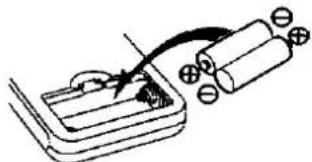
natural_image
Simple line drawing of a battery connected to a switch and two batteries (no text or symbols)Insert the batteries included.
When you need to replace these batteries, use two UM-4 "AAA", IEC R03 (1.5 V) or equivalent batteries.
3

natural_image
Simple line drawing of a mechanical component with a curved handle and mounting holes (no text or symbols)Close the cover.
Use of batteries
Do not mix old and new batteries or batteries of different types (carbon and alkaline, etc.).
Replace the batteries if commands from the remote control transmitter do not operate the unit even when the transmitter is held close to the front panel.
The average battery life is about one year. Although the battery life varies depending on how often the device is used, you should generally replace the batteries about once a year.
If you will not be using the remote control for a long period of time, remove the batteries and store them in a cool, dark place.
- Do not use rechargeable-type (nickel-cadmium) batteries.
- Do not attempt to recharge alkaline or carbon batteries.
- Never subject batteries to excessive heat or flame; do not attempt to disassemble them; and be sure they are not short-circuited.
●Always remove old, weak, or worn-out batteries promptly and dispose of them properly.
If a battery leaks, remove all batteries and dispose of them properly. Thoroughly clean the battery compartment before inserting new batteries.
If the leaking electrolyte comes into contact with skin or clothes, flush with water immediately.
- Do not dispose of used batteries in household rubbish.
Operation notes

About 7 meters in front of the sensor (The actual range will depend on the angle at which the remote control is used.)
Aim the remote control transmission window toward the deck's sensor. Avoid any obstacles.
Use the remote control within a 60-degree angle of the deck.
The reachable distance is within 7 meters directly facing toward the deck.
Be sure the transmission window and the deck's sensor are free from dust. Excessive dust might prevent reception.
- If direct sunlight or other strong light source strikes the remote control signal sensor part of the deck, it may impair the remote control's operation. If there is a problem, place the deck away from the light source.
- If the deck is installed in a rack with glass doors, the glass doors' thickness or color might make it necessary to use the remote-control transmitter a shorter distance from the system.
DCC Tape Playback

1
TIMER
PLAY OFF REC

Set the timer switch to OFF.
2

Switch on the power.
NO CASSETTE
"NO CASSETTE" appears, indicating that no cassette tape has been loaded.
3

Open the cassette tray.
OPEN
4
5
Load the cassette tape.
(See page on right.)
Close the cassette tray.
The information recorded on the cassette tape is now read.
(See page on right.)
A short length of the tape will now be wound up.
CLOSE

FEAJING
6
Start playback.
The play indicator lights.

Loading a DCC tape
Load the cassette tape on the cassette tray.
Position the cassette tape with its slider toward the deck.
Load the tape with the label side facing up.

When the cassette tape has not been loaded properly, the display shown below appears and the cassette tray opens automatically. Check the direction in which the cassette tape was loaded, load it correctly and then close the cassette tray.
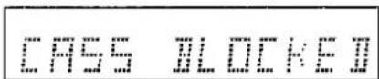
(CASSETTE BLOCKED)
Removing a cassette tape

Temporarily stopping the playback

The play indicator flashes. Press the play button to resume playback.
Stopping the playback

The play indicator goes off.
Display of cassette tape information
What appears on the display will differ according to the cassette tape which is to be played back.
Prerecorded DCC music tapes
Album title display
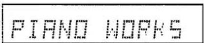
The track number and its play time may appear instead.
DCC recording tapes with time information recorded
Time display

DCC recording tapes without time information recorded
Tape counter display
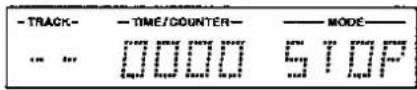
How to use headphones
1 Reduce the volume level.
2 Connect the headphones to the headphones jack and adjust the volume level.
Avoid listening for prolonged periods of time to prevent hearing damage.
What Appears on the Display
Counter display
Selecting the counter display

Normally, the track number and amount of play time elapsed are shown on the display. Each time the COUNTER button is pressed, the counter display changes in the sequence shown in the table below.
Resetting the tape counter

The counter display is returned to "0000".
| Counter mode | Description | Display |
| 1 Track no. and amount of play time elapsedTRACK | The amount of play time that has elapsed from the start of a track is indicated for each track. | 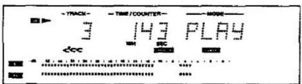 ↓ ↓ |
| 2 Track no. and amount of absolute play time elapsedABS | The time elapsed from the start of the tape until the current recording or playback position on the tape is indicated in minutes/seconds. During recording this time is automatically recorded to enable the tape position to be checked or a particular position on the tape to be searched accurately. The time is not displayed if it was not written during recording. |  ↓ ↓ |
| 3 Track no. and total remaining time on tape REM TOTAL | The remaining time on the tape is indicated in minutes/seconds. This makes it possible to check how much time is left on the tape during tape editing operations. Use this display only as a general guideline since there may be a slight discrepancy from the actual amount of tape remaining. |  ↓ ↓ |
| 4 Track no. and tape counter count | The count displayed corresponds to the rotational speed of the tape reel. Select this position when the absolute time has not been written. |
The time information is not displayed if the track number or absolute time has not been written properly such as when recording or playback was commenced from a point midway along the tape. When an analog cassette tape is used, only the tape counter count will appear.

Only bars will appear.
Text information display
The text information can be recalled when a prerecorded DCC music tape bought from a music store is played back.
Selecting the text information

Each time this button is pressed, the text information to be displayed is selected in the sequence given on the next page.
“Text Information” refers to the title of the album, name of the artist, titles of the tracks, total number of tracks on the tape and total play time which are recorded on prerecorded DCC music tapes, and it is this information which is displayed.
"READING" appears while the information is being retrieved from the tape, and the text information is displayed after this.
| Text mode | Display |
| 1 Title of album | Example: When "PIANO WORKS" is the title of the album Up to 12 characters are displayed. Depending on the length of the title, part of it may not be displayed. Up to 12 characters are displayed. Depending on the length of the title, part of it may not be displayed. |
| 2 Name of artist | Example: When "BEETHOVEN" is the name of the artist |
| 3 Title of track now being played | Example: When "MOONLIGHT" is the title of the track |
| 4 Total number of tracks on tape and total play time | Example: When there are 12 tracks on the tape altogether with a total play time of 43 minutes 8 seconds |
The following display appears for tapes on which text information has not been recorded or for analog cassette tapes:
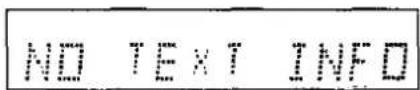
(NO TEXT INFORMATION)
The following display appears for tapes whose total play time cannot be read accurately:

(NO TOC INFORMATION)
Handy Playback Functions Provided by the Deck
Changing the tape run direction (reverse function)

In the stop mode
Side A: A
Side B: B
Normally, the both sides playback mode is set. The one-side playback mode cannot be set.
During playback
Side A playback: A ▶ Side B playback: ◀ B
Rewinding and fast forwarding the tape
In the stop mode:
REW

or

The tape travel direction differs for sides A and B.
| During rewinding | During fast forwarding | |
| Side A | ||
| Side B |
Locating a particular position on the tape (search function)
When one of these buttons is pressed during playback, the tape will be rewound or fast forwarded only for as long as the button is kept depressed.
The playback sound cannot be heard during the search.

Skipping to a particular track (skip play)
Provided that the start mark (see page 40) has been written, the skip function will work even for tapes on which the track numbers have not been written.
Skipping to the next track (Forward skip play)
During playback:
Each time this button is pressed, the tape jumps to the start of the next track, and playback is resumed.
In the stop mode:

Each time this button is pressed, the tape jumps to the start of the next track, and the tape stops.
Skipping to the previous track (Reverse skip play)
During playback:
Each time this button is pressed, the tape jumps to the start of the previous track, and playback is resumed.
In the stop mode:
Each time this button is pressed, the tape jumps to the start of the previous track, and the tape stops.
Displays in the skip mode
With a prerecorded DCC music tape:
The display shows the next track number if the tape is skipped ahead or the previous track number if it is skipped back.

With a DCC tape whose track numbers are not displayed:
If the tape is skipped ahead, the number of times that the button is pressed is indicated with a plus "+" sign.
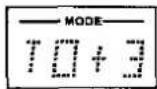
If the tape is skipped back, the number of times that the button is pressed is indicated with a minus “-” sign.

The "TO" display is cleared when the number of tracks involved exceeds 9.
Listening again from the start of the track now being played (replay function)
During playback:

The tape is returned to the start of the track now being played, and playback is resumed.
The search operation may not be performed properly if it is conducted in the leader tape section (where the time is indicated as a bar display) or lead-in section (where the time is indicated as a minus value) since no tracks have been recorded in these sections. (See page 32.)
Selecting tracks by their titles (title search)
The title of each track can be displayed so as to select a particular track to be played.
This function is operational only with prerecorded DCC music tapes purchased from a music store.

3


Search the title of the track which is to be played.
The title of the previous track is displayed.
The title of the next track is displayed.
"READING" appears when the title information has not been read and the title is displayed after the text information has been read.
4

Start playback after the designated track has been searched.
Playing back a track or tape repeatedly (repeat play)
The track being played or all the tracks on the tape can be played repeatedly.

To repeatedly play the track being played: Press the button once.
REPEAT TRACK
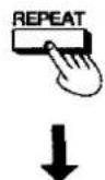
To repeatedly play all the tracks: Press the button again.
CONT REPEAT

To release the repeat play mode: Press the button once more.
The repeat mode indicator now goes off.
Handy Playback Functions Provided by Remote Controller
Starting playback from a particular track number (direct playback)

This function is operational only when a prerecorded DCC music tape purchased from a music store is to be played back. (It is not operational when a DCC tape for recording is to be played back.)
Select the track by means of the track number.
During playback or in the stop mode:

Designate the number of the desired track.
Example: When track no. 3 has been designated.

After the track has been searched, playback commences automatically.
Designating track no. 10 or above
Designate a double-digit track using the track number buttons. For instance, to start playback from track no. 10, proceed as follows:
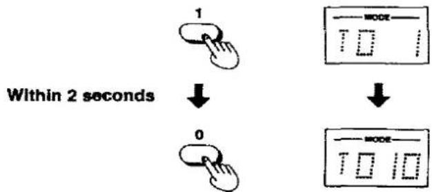
flowchart
graph TD
    A["1 Hand Icon"] --> B["Downward Arrow"]
    C["0 Hand Icon"] --> D["Downward Arrow"]
    E["MODE Display"] --> F["Downward Display"]
After the track has been searched, playback commences automatically.
The following display appears when a number of a track not recorded on the cassette tape has been designated.

Playing back the intros of tracks (music scan)

In the stop mode:

The intro of each track recorded on the tape is played back for about 10 seconds. The play indicator flashes while the next track is being searched.
Playing back the track whose intro is now playing

The tape returns to the start of the track whose intro was being played. when the button was pressed, and that track is played back.
Stopping the intro playback
Adjusting the output level
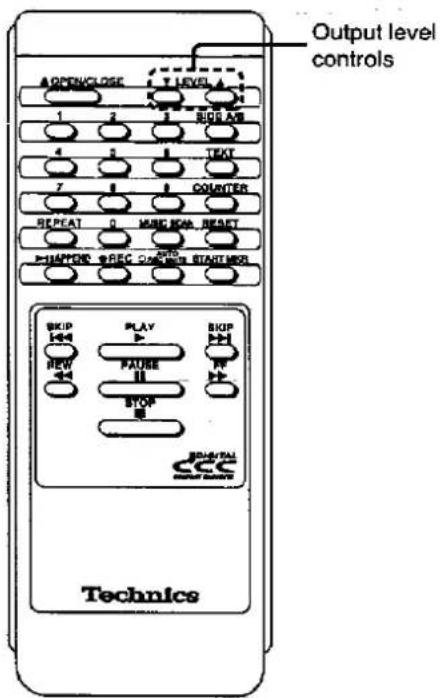
When connection has been made to the deck's analog variable output connector (VARIABLE) (see page 9). Instead of adjusting the amplifier's volume, the sound level can be adjusted using the deck's remote controller.

Adjust the output level of the headphones using the headphones volume control.
Analog Cassette Tape Playback
| 1 | TIMER
PLAY OFF REC
 | Set the timer switch to OFF. | |
| 2 |  | Switch on the power. | NO CASSETTE "NO CASSETTE" appears, indicating that no cassette tape has been loaded. |
| 3 | OPEN/CLOSE
 | Open the cassette tray. | OPEN |
| 4 | Load the cassette tape. (See page on right.) | ||
| 5 | OPEN/CLOSE
 | Close the cassette tray. | CLOSE =5 0000 STOP =5 0000 STOP |
| 6 | DOLBY NR
B OFF C
 | Select the type of Dolby noise reduction. | Dolby B or C lights depending on the position selected by the Dolby NR switch. |
7
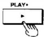
Start playback.
The play indicator lights.

Loading an analog cassette tape
Load the cassette tape onto the cassette tray.
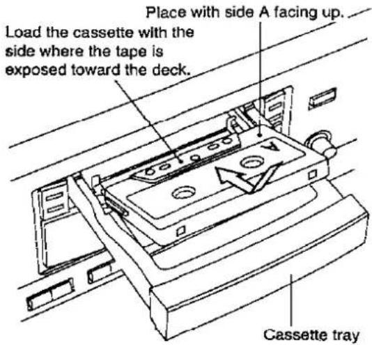
When the cassette tape has not been loaded properly, the display shown below appears and the cassette tray opens automatically. Check the direction in which the cassette tape was loaded, load it correctly and then close the cassette tray.
CHSS BLOCKED II
(CASSETTE BLOCKED)
Removing the cassette tape

Temporarily stopping playback


(PAUSE)
The play indicator flashes. Press the play button to resume playback.
Stopping playback

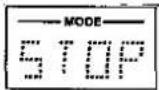
The play indicator goes off.
Setting the Dolby NR system
The Dolby NR system can be used when playing back analog cassette tapes.
This deck is equipped with Dolby type B and type C. Select the same type of system that was used for recording.
Set the Dolby NR selector to OFF when listening to a tape which was not recorded using the Dolby NR system.
About the Dolby Noise Reduction system
Using Dolby NR reduces tape hiss in the high-frequency range. It boosts the level of the high-frequency program content during recording, and lowers it by the same amount during playback, simultaneously reducing high-frequency noise incurred during the recording process.
Dolby noise reduction manufactured under license from Dolby Laboratories Licensing Corporation. "DOLBY" and the double-D symbol are trademarks of Dolby Laboratories Licensing Corporation.
Changing the tape run direction (reverse function)


Normally, the both sides playback mode (≡⊃) is set.
The one-side playback mode cannot be set.
When playback is started from side B, the tape counter display is counted down.
Rewinding or fast forwarding the tape
In the stop mode:

The tape travel direction differs for sides A and B.
Locating a particular position on the tape (search function)
When one of these buttons is pressed during playback, the tape will be rewound or fast forwarded only for as long as the button is kept depressed. The playback sound cannot be heard during the search.
Finding the start of tracks (TPS function)
During playback, the start of a particular track can be located and that track played back.
(TPS: Tape Program Sensor)
Finding the start of the next track
During playback:

In the stop mode:

Each time this button is pressed, the tape jumps to the start of the next track, and playback is resumed.
Each time this button is pressed, the tape jumps to the start of the next track, and the tape stops.
In the stop mode:

Each time this button is pressed, the tape jumps to the start of the previous track, and the tape stops.
TPS may not operate properly in the following circumstances:
- When there is noise in the gaps between tracks
- When the unrecorded blanks between tracks are 4 seconds or less in length
- When tracks have sections with particularly low recording levels or silent passages
- When the play time is less than 10 seconds from the start of the track being heard to the start of the next track
- When the tape was recorded with fade-in and fade-out effects for the intervals between tracks
Finding the start of the previous track
During playback:
Each time this button is pressed, the tape jumps to the start of the previous track, and playback is resumed.
Listening again from the start of the track now being played (replay function)
During playback:

The tape is returned to the start of the track now being played, and playback is resumed.
Playing back the tape repeatedly (repeat play)
In the case of analog cassette tapes, it is possible to repeatedly play all the tracks on the tape but not a particular track.

The following display appears.

CONT REPEAT
Releasing the repeat play function

The display changes to what is shown below.

Quick reverse function
This function serves to detect the leader tape section and in about one second automatically change the playback direction.
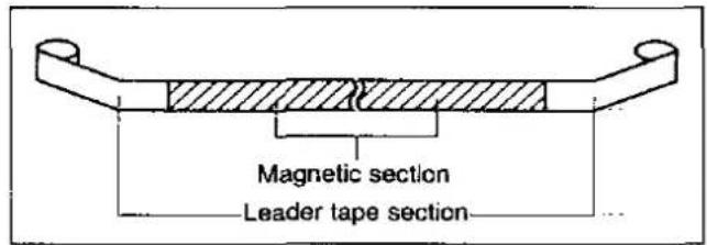
- This function becomes operational only when about 15 seconds have elapsed after the start of playback in order to prevent the leader tape section at the beginning of the tape from being detected.
- When quick reverse does not operate, the tape direction is reversed at the end of the tape.
- This function does not work with a tape which does not have a leader section.
- This function may not work with tapes which have a colored leader section, with dusty or dirty tapes or with a thin magnetic layer.
Concerning analog cassette tapes
Selection of cassette tapes
Do not use the 120-minute (or longer) tapes in this unit.
Because the tape is very thin, it might stretch during use, causing unstable tape movement. This may result in the tape becoming tangled in the rotating parts of the cassette deck.
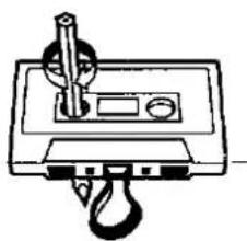
Tape slack
Use a pencil or similar object to take up the slack.
natural_image
Simple line drawing of a mechanical device with a lever and handle (no text or symbols)Tape slack may cause the tape to break.
Improper tape storage
You can damage tape if you store it in the following ways:
1) In high temperature [95°F (35°C) or higher] or high humidity (80% or higher) areas.
2) In a strong magnetic field (near a speaker, on top of a TV, etc.). This can erase a recording.
3) In direct sunlight.
Digital Input Recording (DCC Tapes)
Recording from the start of a tape
Digital recordings can be made from CDs, DATs, or the digital signals used in satellite broadcasts received by a BS tuner.
Refer to page 38 when recording from midway through a tape (append recording).
Upon completion of recording on side A, the recording side is automatically switched to B and recording continues.
Preparations:
-
Check that the "accidental erasure prevention tab" on the DCC tape for recording is set to the recording position. (See page 11.)
-
Load the cassette tape. (See page 17.)

Play indicator
1 INPUT SELECTOR COAXIAL ANALOG OPTICAL

Set the input selector to one of the "DIGITAL" inputs.
Depending on the connections made, set it to "COAXIAL" or "OPTICAL".

Check that the side to be recorded on is side A, and rewind the tape to its beginning.
Even if the tape is new, be sure to rewind it first so that the absolute time will be written. Do not operate any other button until the tape automatically comes to a stop after rewinding.

Set the deck to the recording standby mode.
After the lead-in has been written onto the tape, the deck is set to the recording standby mode.
This takes about 30 seconds.
(See page 32.)
The recording indicator lights and the play indicator flashes. The input indicator lights.
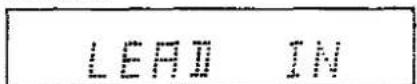
Writing the lead-in
Beginning of tape
Recording standby mode

4

Select the track number writing mode.
This button selects automatic or manual track number writing. (See next page.)
5

Start recording and start playing the source which is to be recorded.

The sound can be monitored through the speakers or headphones while it is being recorded.
Nothing can be recorded on the lead-in area (where the time is indicated as a minus value when the tape has been rewound). (See next page.)
Check the connections again when the COAXIAL or OPTICAL input indicator flashes in the recording standby mode.
●The input source cannot be switched during recording.
- There is no need to adjust the recording level or recording balance during digital input recording.
- When the cassette is ejected or the tape side is changed during recording, the following display appears.

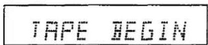
When using a tape for the first time, be absolutely sure to press the rewind button to rewind the tape to its beginning, and then press the record button to write LEAD-IN onto the tape.
Temporarily stopping a recording


(REC PAUSE)
The recording indicator lights and the play indicator flashes. Press the play button to resume recording. A track number is added at the position where the recording was commenced.
Stopping a recording

The recording and play indicators go off. The "use again" marker denoting where the recording is to be followed is written at the position where the recording is stopped. (See page 42.)
Writing the track numbers
If recording is started when a track number is displayed, the track number can be written at that time.
Writing the track numbers automatically

Check that the auto track number write indicator is lighted.
AUTO
The auto track number writing mode is established when the power is switched on.
The auto track number writing function is operational only for recordings from CDs, DATs and other DCCs. It may not work on some models.
Writing the track numbers manually
During recording:

Check that the auto track number write indicator has gone off.
Press this button where the track number is to be written. Each time it is pressed, the track numbers are written in sequence.
If the play button is pressed after the pause button or auto rec mute button was pressed during recording, the track number is added at that position.
The track number display can be checked by observing the track number indicator.

Reference:
Only the start marker is written when the track numbers are not displayed but the track numbers can be added later by renumbering. (See page 50.)
What is the "LEAD-IN" area?

"LEAD-iN" is an area on the tape between the leader tape section and start of the first track where digital signals are written in order to ensure that the digital audio signals will be played back properly from the start of the first track.
When the tape is rewound to its beginning, the deck rewinds the tape as far as the leader tape section where it is set to the recording standby mode, and then the LEAD-IN area extending for about 10 seconds is automatically written onto the tape.
After the LEAD-IN area has been written, recording can be performed.
Precautions for digital input recording
The following tapes cannot be used for recording:
- Prerecorded DCC music tapes sold in a store
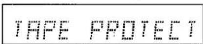
- DCC tapes set to the recording prohibit status
- Analog cassette tapes
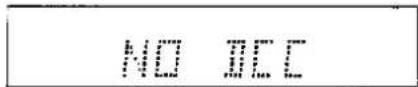
The following display will appear when a digital source is not connected or when the power of the source unit has not been turned on:

(CHECK DIGITAL INPUT)
In cases like this, recording is commenced when the dock is returned to the recording standby mode and the digital signals have been restored.
Tape recordings made with digital signals from a CD player, DAT or other DCC cannot be recorded onto the tape in this deck in the form of digital signals. (See pages 60 and 61.)
Sampling frequencies
Three sampling frequencies—48 kHz, 44.1 kHz and 32 kHz—are available for changing analog signals into digital signals.
48 kHz: DAT tapes recorded with analog input signals
Satellite broadcast B mode, etc.
44.1 kHz: Prerecorded DCC music tapes sold in stores
DCC tapes with analog recording from CDs, etc.
(On this unit, this is indicated as "44 kHz".)
32 kHz: Satellite broadcast A mode, etc.
The sampling frequency indicator display is switched automatically in response to the input signals.
Analog Input Recording (DCC Tapes)
Recording from the start of a tape
Refer to page 38 for recording from midway through a tape (append recording).
Upon completion of recording on side A, the recording side is automatically switched to B and recording continues.
Preparations:
-
Check that the "accidental erasure prevention tab" on the DCC tape for recording is set to the recording position. (See page 11.)
-
Load the cassette tape. (See page 17.)
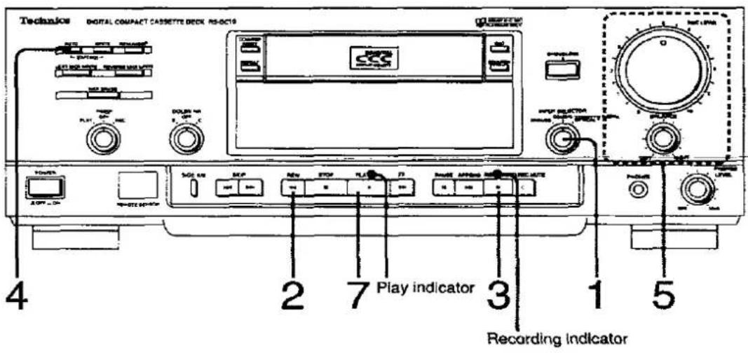
1
INPUT SELECTOR COAXIAL ANALOG. . OPTICAL

Set the input selector to "ANALOG".
2

Check that the side to be recorded is side A, and rewind the tape to its beginning.
Even if the tape is new, be sure to rewind it first so that the absolute time will be written. Do not operate any other button until the tape automatically comes to a stop after rewinding.
3
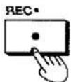
Set the deck to the recording standby mode.
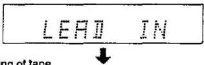
After the lead-in has been written onto the tape, the deck is set to the recording standby mode.
This takes about 30 seconds.
(See page 32.)
The recording indicator lights and the play indicator flashes. The analog input indicator lights.
Writing the lead-in


4

Select the track number writing mode.
This button selects automatic or manual track number writing. (See page 32.)
5

Start playing the source which is to be recorded, and adjust the recording level.
(See next page.)

6
Return the played source to its original state.
7

Start recording and start playing the source which is to be recorded.
The recording and play Indicators light.

Temporarily stopping a recording


(REC PAUSE)
The recording indicator lights and the play indicator flashes. Press the play button to resume recording. A track number is added at the position where the recording was commenced.
Stopping a recording

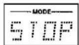
The recording and play indicators go off. The "use again" marker denoting where the recording is to be followed on is written at the position where the recording is stopped. (See page 42.)
Adjusting the recording level

Adjust the recording level.
Adjust the recording balance between the left and right channels.
While observing the peak level meter displays, turn the recording level control and adjust it so that the meter indication does not exceed "0 dB" at the track's peak level and yet it hovers as closely as possible around the "0 dB" mark. The bar display holds the peak value for about 1 second—a feature which is very useful for ascertaining the maximum input.
Peak level meter
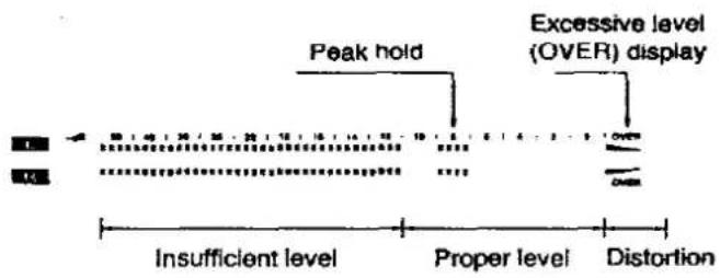
Bear in mind that a display exceeding "0 dB" and entering the "OVER" area will mean that the sound will be distorted during playback.
Precautions for analog input recording
With auto track number writing:
●The unrecorded blanks between tracks may not be detected if these blanks in the source sound being recorded contain a high level of noise. In cases like this, the start marker (see page 40) will not be written.
- Any part of a track with a silent or nearly silent passage resembling an unrecorded blank may be identified as an unrecorded blank, and a start marker may be written.
●After recording has commenced, an unrecorded blank lasts for about 3 seconds or more and then the sound begins to be heard. This is where the track number and start marker are automatically written.
Various Recording Methods (DCC Tapes)
Creating the unrecorded blanks

Creating an unrecorded blank where the recording is to commence
When recording from a point midway through a tape, the blank will clearly identify where the previous recording ends and the new recording begins.
1 In the stop mode:

Set the deck to the recording standby mode.
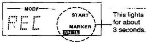
2

Create an unrecorded blank lasting about 3 seconds.

After the indicator lights for about 3 seconds, the deck is set to the recording standby mode.
The track number is not added when the unrecorded blank is written.
Creating unrecorded blanks during recording
This is useful when eliminating unwanted sections or noise.
During recording:

Create an unrecorded blank lasting about 3 seconds.
After the unrecorded blank has been created, the deck is set to the recording standby mode.
Re-recording

The track number is added at the start of the track the recording of which is to be commenced.
Reference:
When a new recording is made on a recorded tape, the previous recording is automatically erased.
Recording from midway through a tape (append recording)
The absolute time written may not be accurate if the append recording is conducted after the tape is fast forwarded or rewound. The append recording function makes it possible to search the position of the use again marker (see page 42) written on the tape and set the deck to the recording standby mode. When append recording is performed using this method described below, no unrecorded parts will remain on the tape, and the absolute time can be recorded uninterrupted.
Preparations:
-
Check that the "accidental erasure prevention tab" on the DCC tape for recording is set to the recording position. (See page 11.)
-
Load the cassette tape. (See page 17.)

1
INPUT SELECTOR COAKIAL ANALOG . OPTICAL

Select the input source.
2

Search the position where append recording is to be performed.
The following procedures will be performed automatically.
(1) Search the position where the previous recording ended.
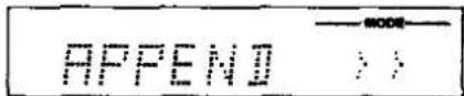
(2) Play back the last 10 seconds or so of the track.

(3) The recording standby mode is established.
3 Check the append recording position.
After playing back the last 10 seconds of the last track, the deck is set to the recording standby mode with the number following the number of the last track.

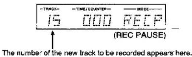
When several use again markers have been written on the tape, the deck is set to the recording standby mode where the first of these markers is written.
If the tape position is not where the recording is to start
When the append button is pressed again while the last 10 seconds of the last track are being played or while the deck is in the recording standby mode, the position of the next use again marker written on the tape is searched.
Bear In mind that in the following case the deck will be set to the recording standby mode at the beginning of the tape.

- When the append button was pressed at the leader tape section:
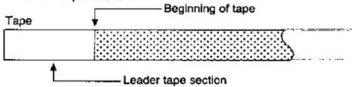
- When the position where the previous recording was stopped could not be searched because of the tape travel mode.
(with lengthy unrecorded parts on the tape) In this case, the search changes to side A after side B is searched, and after the first 10 seconds of the first track have been played back, the deck is set to the recording standby mode.
In cases 1 and 2, press the append button again, and check that the unit is set to the recording standby mode at the number of the track following the last track.
- When no use again markers have been written on the tape: in this case, the append recording function cannot be used.
4

Select the track number writing mode.
This button selects automatic or manual track number writing.
5 Start the recording.
With digital inputs:
Perform step 5 of "Digital Input Recording" (see pages 30 and 31).
With analog inputs:
Perform steps 5 to 7 of "Analog Input
Recording" (see pages 34 and 35).
References:
- The input source can be monitored in the recording standby mode.
- With a tape which has been recorded up to the end of side B, the search changes to side A after searching side B, the first 10 seconds of the first track are played back, and the unit stops at the beginning of the tape.
Types of Sub Codes for Editing and Their Functions
In addition to the audio signals used for recording purposes, the DCC system is provided with a function for writing signals called "sub codes" which come in handy for searching tracks during playback, editing and recording.
When writing the sub codes, check that the accidental erasure prevention tab on the DCC tape for recording is set to the recording position.
Recording and marker editing are not possible on prerecorded DCC music tapes.
Start markers and track numbers
| Type of sub code | Main function | Description | Page no. |
| Start markers:Each of these indicates the start of a track. | Used to find where each track begins. | They are written for about 3 seconds at the start of each track.(only on DCC tapes for recording)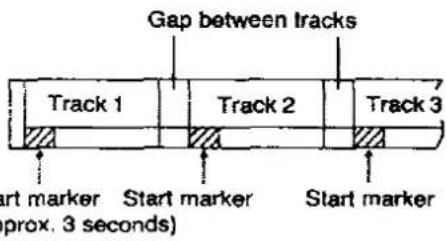 Sta(ap) Sta(ap) | 30–32 |
| Track numbers:Each of these represents a track. | Used when skipping to a particular track and starting playback from that track | In the case of a DCC tape for recording, these numbers are automatically written at the start marker positions.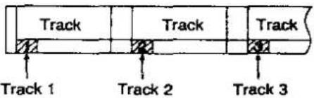 | 32 |
Editing of start markers and track numbers
| Editing item | Description of editing | Page No. | |
| Automatic writing | During recording, the start markers and track numbers are automatically written in numerical order. _ | Recording with digitally input signals: The start markers and track numbers are written when the signals indicating where the tracks begin are included among the digital signals supplied to the deck. (Signals indicating where each track begins are not output from CD players, some DAT models or BS tuners.) | 32 |
| Recording with analog input signals: They are written after an unrecorded blank section (level of -60 dB or below) lasting about 3 or more seconds when the sound begins to re-appear. | 36 | ||
| Manual writing | Start makers can be recorded manually at any desired position while the tape is being played back. | 48 | |
| Erasing start markers and track numbers | The start markers and track numbers which have been written can be erased if so required. | 49 | |
| Renumbering of tracks | When start markers have been rewritten, for instance, the tracks can be automatically renumbered in the right sequence from the beginning of the tape. | 50 | |
In the case of a DCC tape for recording, the track numbers may not appear on the display if playback is started from any point in a track.
Markers for editing
| Type of sub code | Main function | Description | Page no. |
| Reverse marker:This serves to change from tape side A to side B at any point on side A. | When there is not enough tape remaining on side A to enable the next track to be recorded in its entirety, the recording this next track can be continued on side B.The recording of the track can be continued on side B even from any point on that side without interrupting the recording. | The side B track numbers and absolute time are written as continuations of those on side A. | 45, 49 |
| When the reverse marker has been written during recording, it will be written temporarily on side B. Upon completion of the recording, be absolutely sure to renumber the tracks and rewrite the marker properly on side A. | 50–51 | ||
| Next marker:This is used to change over from any point on side A to the beginning of side B or to change over from any point on side B to the beginning of side A. | This is convenient for recording separate albums on sides A and B. | The first track on side B is written as track 1, and the absolute time is written starting from 0:00. | 47, 49, 51 |
Absolute time and append recording
| Type of sub code | Main function | Description | Page no. |
| Absolute time:This indicates the amount of time which has elapsed from the start of the tape. It is required to display the time and track numbers. | This comes in handy for checking the tape position or for searching a particular position on a tape accurately. | The absolute time may not be written properly if the tape is fast forwarded or rewound for performing append recording. When recording from any point along a tape, proceed with recording using the append button. (The approximate time is shown while the tape is being fast forwarded or rewound.) | 18, 38 |
| Use again marker:This indicates the position where the previous recording was stopped. It is automatically written at the position where the recording is stopped. | This comes in handy when finding the end of a previous recording and appending new material. | When the append button is pressed, the position where the previous recording was stopped (where the use again marker was written) is searched and the unit is set to the recording standby mode. | 31, 38–39, 49 |
Time display
| Type of sub code | Main function | Description | Page no. |
| Elapsed play time: This indicates the amount of time which has elapsed from the start of a track. | This comes in handy when searching a particular position in a track using the elapsed time. | When a DCC tape for recording is played back from a particular point along a tape, the elapsed play time may not be indicated properly. | 18 |
| Remaining time: During playback, this indicates the total time remaining on the tape and not just the time on the side being played. During recording, it indicates the time remaining on one side (A or B) of the tape. | When recording material onto a tape or when using the reverse marker to switch from side A to side B to continue a recording, it is convenient to have the amount of time remaining on one side of the tape indicated at the counter display. | Use this time as a general guideline since it may differ slightly from the actual amount of tape remaining. | 19 |
When this unit is used for recording, the start markers, track numbers, absolute time and play times are written automatically. Once it has been written, any sub code except for the absolute time can be rewritten or erased.
Prerecorded DCC music tapes already have the start markers, track numbers, absolute time, elapsed play time, and total time remaining on the tape written on them.
Marker Editing while Recording is in Progress
Changing the tape side to record (reverse marker)

Reverse marker
This is used to change from tape side A to side B at a point midway through recording so that recording can be continued. It can be written only on side A. During playback, the tape side is automatically switched at the position where the marker is written.
Example: When recording tracks 1 through 5 on side A and then recording tracks 6 through 9 on side B
References:
- It is also possible to record a part of a track on side A and continue with the recording of the rest of the track on side B. In this case, the track number is added.
- It is a good idea to set the counter display to the display indicating the remaining time on one side of the tape.
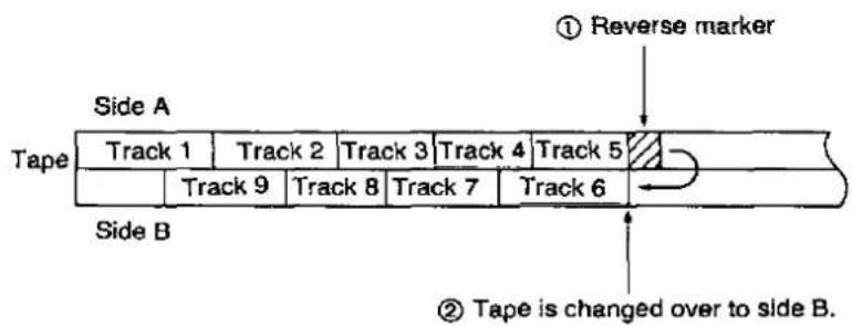
There are two ways of writing the reverse marker.
1. Writing the marker during recording
1 During recording on side A:
Write the reverse marker.
The reverse marker is temporarily written, the tape changes over to side B at that position and the recording is continued. The same track number as that applying to the last track on side A is used.

2 In order to write the marker properly to side A, be absolutely sure to renumber the tracks (See page 50.) upon completion of the recording.
2. Writing the marker in the recording standby mode
1 While the deck is in the standby mode to record on side A:

Write the reverse marker.
After the reverse marker has been written, the tape changes over to side B, and the recording standby mode is established. (See figure on right.)
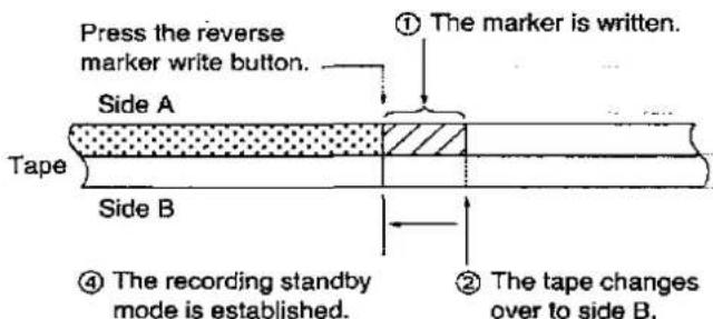
③ The tape is rewound to the reverse position on side A.
2 PLAY• The recording of the next track commences on side B.
When a recording has been made continuously from side A to side B without writing the reverse marker When the tape is switched to side B, the track number is incremented by one and the numbers of each of the subsequent tracks are in turn incremented by one. When recording material from CDs, for instance, it is recommended that the reverse marker be used. Otherwise, the numbers of the tracks recorded on side B will differ from the actual numbers.
Recording continuously on both sides of the tape (next marker)

Next marker
The next marker can be written only in the recording standby mode and on either side A or B. (See page 42.)
When the marker has been written on side A, the tape is automatically fast forwarded during playback, and playback starts from side B. When it has been written on side B, the tape is fast forwarded to the start of side A and then it stops. (Depending on the length of the tape remaining, this may take some time.)
Example: When, for recording 9 tracks, recording tracks 1 through 5 on side A and the remaining 4 tracks on side B

Writing the next marker
Writing the marker on side A
1 While recording is in progress:

Set the deck to the recording standby mode.
2

Write the next marker.
After the next marker has been written, the tape is fast forwarded to the beginning of side B and the recording standby mode is established. (See figure on right.)
3

Record the next track on side B.
The first track on side B is written as track 1, and the absolute time is written starting from 0:00.
Writing the marker from any point on side B
Performs steps 1 and 2 described above.
After the next marker has been written, the tape is fast forwarded to the beginning of side A and then it stops.
Displays during next marker editing (When it has been written on side A)
(1) Writing of next marker
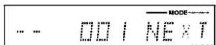

(2) Fast forwarding to beginning of side B


(3) Writing of lead-in


(4) Beginning of tape
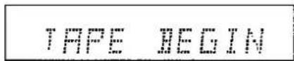

(5) Recording standby mode
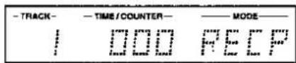
(REC PAUSE)
Marker Editing after Recording

Writing the start marker manually
The start marker can be written at any position while the tape is playing back.
Preparation:
Check that the "accidental erasure prevention tab" on the DCC tape for editing is set to the recording position. (See page 11.)
- The start marker cannot be written onto prerecorded DCC music tapes.
- When an unnecessary start marker has been written, first rewind the tape to a position immediately before the start marker, erase it, and then write the marker by pressing the manual track number write button at the position where the marker is to be written.
- When the start marker has been written manually, the sequence of tracks changes. Proceed with renumbering (see page 50) to allocate new numbers to the tracks.
1 While playing back the tape, locate the position where the recording is to commence.
Write the start marker.
The start marker is written at the position on the tape where the button is pressed.
3 Repeat steps 1 and 2 to write another start marker.
Erasing the written markers
Any or all of the written markers can be erased as and when required.
Preparation: Check that the "accidental erasure prevention tab" on the DCC tape for editing is set to the recording position. (See page 11.)
Erasing start markers (track numbers)
1 While playing back the tape, locate the position where a marker was written.
When the position where a marker was written is reached, the corresponding indicator lights.

Check that "START MARKER" has appeared on the display.
2 In the playback or stop mode:

Erase the marker.
The first marker, which is at the present tape position or at a position within 2.5 seconds from where the marker erase button is pressed, is erased.

The deck is returned to the playback or stop mode after the marker has been erased or if the marker was not written within 2.5 seconds.
3 To delete other markers in succession, repeat steps 1 and 2.
The music signals are muted while markers are being erased but this does not affect the music signals which have been recorded.
References:
●Proceed with renumbering (see page 50) to allocate running numbers to the edited start markers.
- When erasing markers, it is a good idea to set the counter display to the absolute time display in order to verify the marker positions.
Erasing markers used for editing
Erasing the reverse marker or next marker Press the marker erase button while the position one or two seconds before the written marker is being played back.
Erasing use again markers
-
When the append button is pressed, the unit is set to the recording standby mode at a position before the marker which is to be erased.
Check the erasure position since the last 10 seconds of the track will be played back before the deck is set to the recording standby mode. -
Press the stop button and then press the marker erase button.
If the tape arrives at the actual reverse marker or next marker position during playback, it will not be possible to erase the marker since the tape will be switched to side B.
Depending on the tape travel mode, it may not be possible to erase the marker completely with a single attempt at erasing it. In a case like this, press the marker erase button again while the position one or two seconds before the marker is being played back.
Adding running numbers to the edited start markers (renumbering)
Rewrite the track numbers at the start marker positions in sequence from the beginning of the tape when the track sequence has been changed because start markers have been added or deleted.
Preparation:
Check that the "accidental erasure prevention tab" on the DCC tape for editing is set to the recording position. (See page 11.)

1 In the stop mode:

Start renumbering the tracks.
The tape is rewound to the beginning of side A, the start markers are automatically searched, and the tracks are renumbered in sequence starting from track 1.
Stopping the renumbering process

Renumbering cannot be performed on tapes on which the absolute time is not written. Interrupt the renumbering operation and stop the tape. Renumbering may not function properly if the distances between start markers are too short.
Display which appears during renumbering

The absolute time display is shown here.
When the renumbering of side A is completed, the tape is automatically fast forwarded and the renumbering of side B commences.
When, during renumbering, the tape arrives at the position where the start marker was written, the track number is checked, and if it is not written correctly, the tracks are renumbered.
Upon completion of the track renumbering, the tape is rewound to the beginning of side A and it stops.
The reverse marker, etc. will be written properly by the renumbering process.
Renumbering operations
Depending on how the tape has been edited (where on the tape the recording was ended, types of
markers written, etc.), the deck operates in one of the following ways during renumbering.
| Tapes without reverse and next markers written on them | |
| When material has been recorded up to any point along a tape | 1. Renumbering is ended at the position where recording was stopped (where the use again marker was written).2. The tape is rewound to the beginning of side A where it stops. |
| When material has been recorded up to the end of a tape | 1. The tracks are renumbered up to the end of side A.2. The tape is switched to side B (at which time the numbers of the tracks are each incremented by 1), and renumbering is continued.3. Numbering is ended at the position where recording was stopped or at the end of side B.4. The tape is rewound to the beginning of side A where it stops. |
| Tapes with a reverse marker written on them | |
| When the marker was written while the deck was in the recording standby mode | 1. The tracks on side A are renumbered up to the position where the reverse marker was written.2. The tape is switched to side B at the position on side A where the reverse marker was written (at which time the numbers of the tracks are each incremented by 1), and renumbering is continued. |
| When the marker was written while the deck was in the recording mode | With a tape which is unrecorded beyond the reverse mark:1. The tracks on side A are renumbered up to the unrecorded position.2. The tape is switched to side B at the unrecorded position on side A and renumbering is continued. |
| With a tape which still has a previous recording beyond the reverse mark:1. The tracks on side A are renumbered up to, through and beyond the position where the reverse marker write button was pressed.2. When the tracks up to the end of side A are renumbered, the tape is switched to side B, and renumbering is continued.When a use again marker has been written at a point along the tape:Renumbering is ended at that point. (In this case, the use again marker is erased first and then renumbering is resumed.)3. When the tracks are renumbered up to the position (on side B) where the reverse marker write button was pressed, the tape is switched to side A, and the reverse marker is written properly at that position.When a use again marker has been written at a point along the tape:Renumbering is ended at that point. (in this case, the use again marker is erased first and then renumbering is resumed.)4. The tape is switched again to side B, and renumbering is continued. | |
| In any of the above cases, renumbering is ended at the position where the recording was stopped (where the use again marker was written) or at the end of side B, and the tape is rewound to the beginning of side A where it stops. | |
| Tapes with a next marker written on them |
| 1. The tracks on side A are renumbered up to the position where the next marker was written.2. The tape is fast forwarded from the position where the next marker was written to the end of side A.3. The tape is switched to side B, and renumbering is continued. (The first track on side B is written as track 1.)4. Renumbering is ended at the position where the recording was stopped or at the end of side B.5. The tape is rewound to the beginning of side A where it stops. |
Timer Playback/Recording
If this deck is used with an audio timer or a tuner equipped with a timer available from an audio store, it is possible for a tape to be played back at a
particular time to serve as a wake-up call or for the recording of a particular radio broadcast to be commenced automatically.
Timer playback
Preparation:
Load the cassette tape for playback. (See page 17 for DCC tapes and page 27 for analog cassette tapes.)
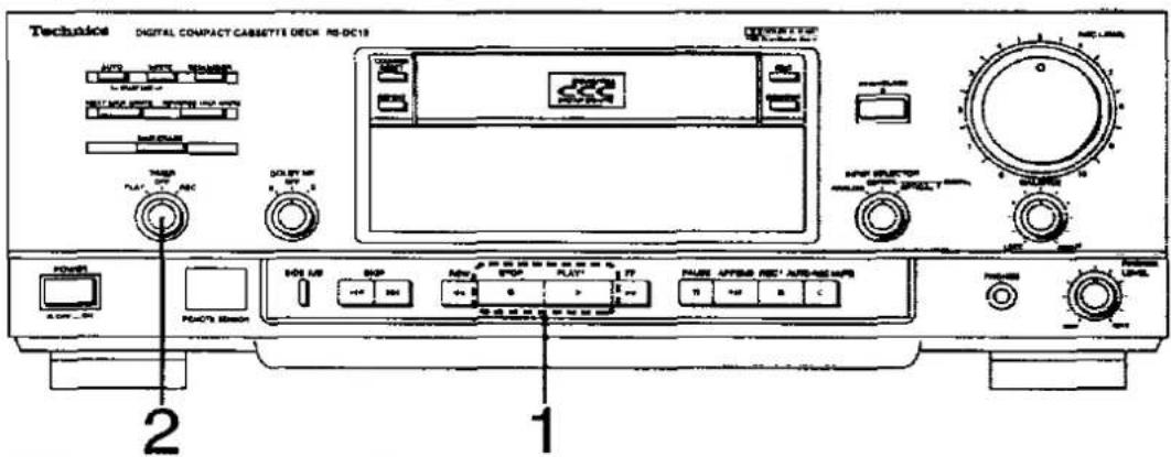
Connections
(signal system connections are omitted)
Connect the power cords of the components as shown in the figure below. (For further details, refer to the Operating Instructions of the timer to be connected to the deck.)

flowchart
graph TD
    A["Power outlet"] --> B["AC OUTLET"]
    B --> C["AC IN ~"]
    C --> D["(BS) tuner (option)"]
    D --> E["AC OUTLET"]
    E --> F["AC IN ~"]
    F --> G["Amplifier (option)"]
    G --> H["Deck"]
    H --> I["Household AC outlet"]
    style A fill:#f9f,stroke:#333
    style I fill:#ccf,stroke:#333
1 Start playback, adjust the amplifier's volume and tone controls and stop the tape where playback is to commence.
2 TIMER SET this selector to PLAY.
PLAY OFF REC
[REDACTED]
3 Set the timer to the desired time.
The deck's power is now turned off.
When the time set by the timer is reached, the deck's power is turned on and playback starts automatically.
Display during timer operation

- Leave the power supplied to the amplifier so that power will be supplied to the deck when it becomes activated by the timer.
- The repeat mode is released during timer playback.
- After timer playback has ended, return the timer switch to the OFF position.
Timer recording (DCC tapes)
Preparations:
- Check that the "accidental erasure prevention tab" on the DCC tape for recording is set to the recording position. (See page 11.)
- Load the DCC tape for recording. (See page 17.)

1 Select the source to be recorded.

Select the input source.

Set the deck to the recording standby mode.
When using a new tape which has never been recorded, be absolutely sure to press the rewind button to rewind the tape to its beginning, press the record button to write the lead-in onto the tape, and then set the deck to the recording standby mode.

Adjust the recording level and recording balance.
(This is not necessary when recording digital input signals.)

Set the timer selector to the REC position.
6 Set the timer to the desired time. The deck's power is now switched off.
When the time set by the timer is reached, the deck's power is turned on and recording starts automatically.
- The auto track number writing mode is established in the case of timer recording.
- Leave the power supplied to the components so that power will be supplied to the deck when it becomes activated by the timer.
- When proceeding with timer recording from any point along the tape, set the timer after having set the position where the recording is to start using the append button.
- It takes a few moments for recording to begin after the timer power has been switched on.
When setting the times on the timer, set the recording start time on the early side to provide some leeway. - Depending on the status of the tape, the absolute time may not be written during timer recording.
●After timer recording has ended, return the timer switch to the OFF position.
Quick Reference Table of Remote Control Operations
Common operations
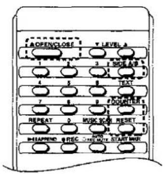
| Function | Button | Page No. |
| Opening/closing the cassette tray |  | 16, 26 |
| Selecting the counter display |  | 18 |
| Resetting the tape counter |  | 18 |
| Selecting the tape travel direction |  | 21, 28 |
Playback

| Function | Button | Page No. |
| Starting playback |  | 17, 27 |
| Temporarily stopping playback |  | 17, 27 |
| Stopping playback | STOP | 17, 27 |
| Selecting the text information (prerecorded DCC music tapes only) |  | 19 |
| Selecting the repeat play mode |  | 23, 29 |
| Fast forwarding the tape |  | 21, 28 |
| Rewinding the tape |  | 21, 28 |
| Skipping ahead |  | 22, 23, 28 |
| Selecting the track's title display | ||
| Skipping back |  | 22, 23, 28 |
| Selecting the track's title display | ||
| Assignment of track numbers | 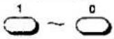 | 24 |
| Playback of track intros |  | 25 |
| Adjustment of output level |  | 25 |
Recording
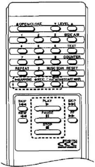
| Function | Button | Page No. |
| Starting recording |  | 31, 35 |
| Temporarily stopping recording |  | 31, 35 |
| Stopping recording |  | 31, 35 |
| Setting the deck to the recording standby mode |  | 30, 34 |
| Append recording |  | 38 |
| Creating unrecorded blanks | [06ZX] | 37 |
Editing
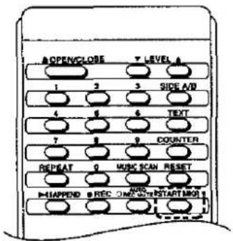
| Function | Button | Page No. |
| Writing the start markers manually |  | 48 |
Troubleshooting Guide
Before requesting service for this unit, check the chart below for a possible cause of the problem you are experiencing. Some simple checks or a minor adjustment on your part may eliminate the problem and restore proper operation.
If you are in doubt about some of the check points, or if the remedies indicated in the chart do not solve the problem, refer to the directory of Authorized Service Centers (enclosed with this unit) to locate a convenient service center, or consult your dealer for instructions.
| Problem | Possible cause(s) | Suggested remedy | Page No. |
| The unit is placed in the record or play mode as soon as the power is switched on. | Timer switch is at REC or PLAY. | Press stop button and set timer switch to OFF. | 52-53 |
| Tape travels but no playback sound is heard. | Amplifier's volume control is at minimum position. | Adjust amplifier's volume by turning its volume control. | - |
| Amplifier's selector is not at DAT or TAPE. | Set selector to position corresponding to what is connected to deck (DAT or TAPE). | 8-9 | |
| Connection has been made to variable output connector and level has been turned down to minimum. | Adjust level using remote controller. | 9, 25 | |
| Noise or distortion in playback sound. | Recording level is much too high or much too low. | Record again at proper recording level. | 36 |
| Playback sound is broken and disconnected. | Dirty head section. | Clean the heads using an optional cleaning tape and re-record. | 58 |
| Worn-out cassette tape. | Use a new cassette tape. | ||
| Something is wrong with sound quality when analog cassette tapes are played back. | Dolby NR switch set to wrong position. | Set Dolby NR to same mode as that used for recording. | 26 |
| No analog input recording. | Cassette tape's accidental erasure prevent tab is closed. | Set tab to open position. | 11 |
| Improper connections with stereo amplifier. | Connect properly. | 8-9 | |
| Recording level control at "0" position. | Adjust recording (Input) level using recording level control. | 36 | |
| Digital input mode has been established. | Set input selector to proper position. | 34 | |
| No editing of DCC tape for recording. | Cassette tape's accidental erasure prevent tab is closed. | Set tab to open position. | 11 |
| No digital input recording. | Analog input mode has been established. | Set input selector to proper position. | 30 |
| Signal prohibiting the copying (recording) of digital recordings is included among input source signals when digital signals are supplied. | Switch to analog input recording. | 34 | |
| Digital selection between optical or coaxial input has not been performed properly. | Set input selector to proper position. | 30 | |
| Search function does not operate properly. | Start marker has not been written properly. | Write start marker. | 40-41 |
| Track numbers or amount of play time elapsed is not displayed properly. | Track numbers have not been written properly. | Provide running numbers to the written start markers. | 50 |
| Cassette tape has been loaded midway through track. | Press rewind button and rewind to start of track. | 21 | |
| No timer recording or playback. | Faulty connections. | Refer to section on connections and connect properly. | 52-53 |
| Timer has not been programmed properly. | Check how to operate the timer again. | ||
| Operating remote controller does not produce expected results. | No cassette tape loaded. | Load cassette tape properly. | 17, 27 |
| Batteries in remote controller have run down. | Replace with new batteries. | 15 | |
| Signals from remote controller do not reach deck. | Check both distance between remote controller and deck and direction in which controller is pointed, check that there is nothing obstructing signal path, and operate at correct position. | 15 |
Maintenance Procedures
Cleaning the head section
Any dust or dirt on the head section (where the tape makes contact) will impair the quality of recording and playback. Obtain the optional cleaning tape and play it back once.
Always be sure to use the optional cleaning tape to clean the deck's head section.
Do not use a demagnetizer.
Under no circumstances must a demagnetizer for analog cassette decks be used since it may damage the head section.
- If the playback quality improves after cleaning but it then deteriorates after only several recording and playback operations, chances are that the cassette tape has
reached the end of its service life. Use a new cassette tape instead. - Consult your dealer if the quality is not improved even after the head section has been cleaned.
- The cleaning tape cannot be used for recording or playback. (Read through the instructions accompanying this tape as well.)
Operation Notes
Always keep the cassette holder closed.
If it is left open, dust will accumulate in the mechanism and cause tape playback or recording performance to deteriorate. Do not touch the inside of the cassette holder.
If the unit is not used for extended periods, remove the cassette tape.
The top of the deck will become hot during use, but this is perfectly normal.
When carrying or storing the unit, take care not to subject it to any severe shocks.
When storing or transporting the unit, be sure also to remove the cassette tape.
Technical Specifications
■ Digital Recording/Playback
| Tape recording system: | Stationary head type DCC |
| Sampling frequencies (Analog input recording): | 44.1 kHz |
| (Playback/ Digital input recording): | 48 kHz, 44.1 kHz, 32 kHz (selected automatically) |
| No. of quantizing bits: | 16-bit linear |
| Audio coding system: | PASC |
| No. of channels: | 2-channel (stereo) |
| Frequency response: | 10 Hz-20,000 Hz (±0.2 dB) |
| (48 kHz sampling frequency): | 10 Hz-22,000 Hz (±0.2 dB) |
| (32 kHz sampling frequency): | 10 Hz-14,500 Hz (±0.2 dB) |
| THD | |
| (Playback): | 0.003% or less (1 kHz, 0 dB) |
| (Recording/ playback): | 0.005% or less (1 kHz, 0 dB) |
| Dynamic range (Playback): | 95 dB or more (A-weighted) |
| (Recording/ playback): | 92 dB or more (A-weighted) |
| SN ratio | |
| (Playback): | 98 dB or more (A-weighted) |
| (Recording/ playback): | 92 dB or more (A-weighted) |
| Channel separation (Playback): | 95 dB or more (1 kHz) |
| (Recording/ playback): | 80 dB or more (1 kHz) |
| Wow and flutter: | Below measurable limit |
■ Analog Cassette Tape Playback
| Deck system: | Analog compact cassette |
| Track system: | 4-track, 2-channel (Stereo) |
| Frequency response (Dolby NR off) | |
| Normal: | 30 Hz-15,000 Hz ±3 dB |
| CrO2: | 30 Hz-16,000 Hz ±3 dB |
| Metal: | 30 Hz-17,000 Hz ±3 dB |
S/N (Signal level=250 nwb/m, CrO₂ type tape)
NR off: 56 dB (A-weighted)
Dolby B NR on: 65 dB (CCIR)
Dalby C NR on: 74 dB (CCIR)
Wow and flutter: 0.07% (WRMS)
±0.2% (DIN)
Terminals
| Analog input | |
| Input sensitivity: | 60 mV (-12 dB) |
| Input impedance: | 47 kΩ |
| Analog output (fixed) | |
| Output level: | 500 mV (DCC -12 dB) |
| Maximal output level: | 2 V (DCC 0 dB) |
| Output impedance: | 440Ω |
| Variable analog | |
| output: | Using remote control |
| Headphones output | |
| Maximum level: | 30 mW+30 mW(32Ω load) |
| Load impedance | |
| range: | 8-600Ω |
| Digital input: | Coaxial 75Ω/Optical(with select SW) |
| Digital output: | Coaxial 75Ω/Optical(parallel output) |
■ Mechanism
| Heads: | 20-channel thin film head |
| Tape drive system: | Single capstan drive (Auto reverse) |
| Tape drive motors | |
| Capstan: | DC servo motor |
| Reel table: | DC motor |
| Tape speed: | 4.76 cm/sec. |
| Fast forward andrewind times: | Approx. 100 sec. with D-60 cassette tape |
General
| Power consumption: | 35 W |
| Power supply | |
| For United | |
| Kingdom: | AC 50 Hz/60 Hz, 240 V |
| For continental | |
| Europe: | AC 50 Hz/60 Hz, 230 V |
| For others: | AC 50/60 Hz, 110 V/120 V/240 V/220 V |
| Dimensions(W×H×D): | 430×153×341 mm |
| Weight: | 8.3 kg |
Note:
Specifications are subject to change without notice.
Weight and dimensions are approximate.
(For United Kingdom only)
This apparatus was produced to BS 800.
SCMS
(Serial Copy Management System)
This unit is equipped with SCMS (Serial Copy Management System). SCMS is a system which allows digital-signal copying of CDs and commercial music DCC tapes only for one "generation". The DCC tape thus recorded cannot be used as a master tape
to produce further generations (serial copies) of the first digital copy. The accompanying Illustrations describe the ways in which recording is possible from each kind of source.
1 DCC tapes recorded digitally from CDs

flowchart
graph TD
    A["CD player (playback)"] -->|Output| B["Digital signal"]
    B -->|Input| C["(Recording possible)"]
    C --> D["First generation"]
    D --> E["(Tape playback)"]
    E -->|Output| F["Digital signal"]
    F -->|Input| G["(Digital recording not possible)"]
Digital-signal recording from a CD can be performed only for the first generation of DCC tape. The DCC tape thus recorded (1st generation) cannot be used as a master to make further digital copies (serial copies).
Digital signals from a CD player recorded on a DAT cannot be recorded in their original form from the DAT tape onto a digital compact cassette tape. Similarly, digital signals from a CD player recorded onto a DCC in their original form cannot be recorded from the DCC tape onto a digital audio tape in their original form. In other words, SCMS restricts the recording of digital signals even when different digital recording equipment such as DAT and DCC are used in combination.
2 DCC tapes recorded digitally from a commercially produced music DCC tape or DAT cassette
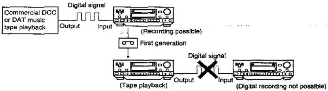
flowchart
graph TD
    A["Commercial DCC or DAT music tape playback"] -->|Output| B["Digital signal"]
    B -->|Input| C["(Recording possible)"]
    C --> D["First generation"]
    D --> E["(Tape playback)"]
    E -->|Output| F["Digital signal"]
    F -->|Input| G["(Digital recording not possible)"]
Digital-signal recording from a commercially produced DCC or DAT music tape can be performed only for the first generation of DCC tape. The DCC tape thus recorded (1st generation) cannot be used as a master to make further digital copies (serial copies).
However, it should be noted that it may not be possible to make digital copies from commercial DCC or DAT music tapes which do not conform to the SCMS format.
3 DCC tape recorded from analog input terminals (when thereafter recorded digitally)

flowchart
graph TD
    A["Record player, tuner, etc. (analog component)"] --> B["Analog signal"]
    B --> C["(Recording possible)"]
    C --> D["First generation"]
    D --> E["(Tape playback)"]
    E --> F["Digital signal"]
    F --> G["(Digital recording possible)"]
    G --> H["Second generation"]
    H --> I["(Tape playback)"]
    I --> J["Digital signal"]
    J --> K["(Recording not possible)"]
    style A fill:#f9f,stroke:#333
    style B fill:#ccf,stroke:#333
    style C fill:#cfc,stroke:#333
    style D fill:#fcc,stroke:#333
    style E fill:#cff,stroke:#333
    style F fill:#ffc,stroke:#333
    style G fill:#ffc,stroke:#333
    style H fill:#ffc,stroke:#333
    style I fill:#ffc,stroke:#333
    style J fill:#ffc,stroke:#333
    style K fill:#ffc,stroke:#333
When the DCC recording of an analog source is used as the master tape for further digital-signal DCC copies, up to two generations of digital copies can be made. However, the second generation of such
copies cannot be used as the master tape for making third and subsequent generations of digital copies (serial coies).
4 DCC tapes recorded from analog input terminals (when recorded in analog thereafter)
When recording is performed from the analog input terminals, no restrictions are made on copies, in the same way as for conventional audio cassette tape recorders. Accordingly, even in cases where
recording of the digital signal (digital copy) is not possible, the analog input and output terminals can be used to perform analog recording.
Digital copy prohibit display
In the following cases, digital signals cannot be recorded in their original form: When recording signals from a source which has been digitally copied once before
The COPY PROHIBIT indicator lights.

When a copy prohibit signal is supplied during recording

When a copy prohibit signal is supplied in the recording standby mode

Memo
- Notes:
- Features
- Dear Stereo Fan
- High-quality digital sound
- Compatible with conventional analog cassette tapes
- Digital technology providing a touch of sophistication and greater convenience
- More enjoyment and fun from listening to music
- Terms used in this manual
- Do not use a demagnetizer.
- Caution for AC mains lead
- (For United Kingdom)
- ("EB" area code model only)
- CAUTION!
- IMPORTANT
- Before use
- How to replace the fuse
- Suggestions for Safety
- ■ Use a standard AC wall outlet
- ■ Grasp the plug when disconnecting the power supply cord
- ■ Place the unit where it will be well ventilated
- ■ Avoid places such as the following: In direct sunlight or in other places where the temperature is high.
- ■ Be sure to place the unit on a flat, level surface.
- ■ Never attempt to repair nor reconstruct this unit
- ■ Take particular care if children are present
- ■ if water is spilled on the unit
- ■ Avoid spray-type insecticides
- ■ Never use alcohol or paint thinner
- ■ Disconnect the power supply cord if the unit will not be used for a long time
- ■ If trouble occurs
- Supplied Accessories
- (For areas except Continental Europe, United Kingdom and Australia)
- Note:
- Table of Contents
- Recording
- Marker Editing
- Timer Operations
- Remote Control Operations
- Useful Information
- Technical Details
- Various Recording Methods .... 37
- Types of Sub Codes for Editing and Their Functions 40
- Marker Editing while Recording is in Progress 44
- Marker Editing after Recording 48
- Timer Playback/Recording 52
- Quick Reference Table of Remote Control Operations 54
- Troubleshooting Guide 56
- Maintenance Procedures 58
- Technical Specifications .... 59
- SCMS (Serial Copy Management System) .... 60
- Connections
- Digital connections
- Digital direct recording
- About Optical Fiber Cables
- To connect optical fiber cables
- About OPTICAL connector
- Analog connections
- Connections to deck's analog output connectors
- Fixed output connectors (FIX)
- Variable output connectors (VARIABLE)
- Installation
- Avoid locations nearby tuners or television sets.
- Types of tapes which can be used
- DCC tapes for recording
- Safeguarding against the accidental erasure of a valuable recording
- To re-record
- Handling precautions
- Storage precautions
- Front Panel Controls and Functions
- Control section
- Display section
- ⑥ Text information/counter display section
- ⑦ Marker indicator section
- DCC indicator ( dcc )
- Counter display indicators
- ⑩ Sampling frequency Indicators (48kHz, 44kHz, 32kHz)
- ⑪ Input indicator section
- ⑫ Digital copy prohibit indicator (COPY PROHIBIT)
- Concerning the Remote Control
- Battery installation
- Use of batteries
- Operation notes
- DCC Tape Playback
- 1
- 2
- 3
- 4
- 5
- Start playback.
- Loading a DCC tape
- Removing a cassette tape
- Temporarily stopping the playback
- Stopping the playback
- Display of cassette tape information
- Prerecorded DCC music tapes
- DCC recording tapes with time information recorded
- DCC recording tapes without time information recorded
- How to use headphones
- What Appears on the Display
- Counter display
- Selecting the counter display
- Resetting the tape counter
- Text information display
- Selecting the text information
- Handy Playback Functions Provided by the Deck
- Changing the tape run direction (reverse function)
- Rewinding and fast forwarding the tape
- Locating a particular position on the tape (search function)
- Skipping to a particular track (skip play)
- Skipping to the next track (Forward skip play)
- Skipping to the previous track (Reverse skip play)
- Displays in the skip mode
- Listening again from the start of the track now being played (replay function)
- Selecting tracks by their titles (title search)
- Playing back a track or tape repeatedly (repeat play)
- Handy Playback Functions Provided by Remote Controller
- Starting playback from a particular track number (direct playback)
- Select the track by means of the track number.
- Designating track no. 10 or above
- Playing back the intros of tracks (music scan)
- Playing back the track whose intro is now playing
- Stopping the intro playback
- Adjusting the output level
- Loading an analog cassette tape
- Removing the cassette tape
- Temporarily stopping playback
- Stopping playback
- Setting the Dolby NR system
- About the Dolby Noise Reduction system
- Rewinding or fast forwarding the tape
- Finding the start of tracks (TPS function)
- Finding the start of the next track
- Finding the start of the previous track
- Playing back the tape repeatedly (repeat play)
- Releasing the repeat play function
- Quick reverse function
- Concerning analog cassette tapes
- Selection of cassette tapes
- Tape slack
- Improper tape storage
- Digital Input Recording (DCC Tapes)
- Recording from the start of a tape
- Preparations:
- Select the track number writing mode.
- Start recording and start playing the source which is to be recorded.
- Temporarily stopping a recording
- Stopping a recording
- Writing the track numbers
- Writing the track numbers automatically
- AUTO
- Writing the track numbers manually
- Reference:
- What is the "LEAD-IN" area?
- Precautions for digital input recording
- Sampling frequencies
- Analog Input Recording (DCC Tapes)
- 6
- 7
- Adjusting the recording level
- Precautions for analog input recording
- With auto track number writing:
- Various Recording Methods (DCC Tapes)
- Creating an unrecorded blank where the recording is to commence
- Creating unrecorded blanks during recording
- Recording from midway through a tape (append recording)
- Check the append recording position.
- If the tape position is not where the recording is to start
- Start the recording.
- References:
- Types of Sub Codes for Editing and Their Functions
- Marker Editing while Recording is in Progress
- Changing the tape side to record (reverse marker)
- Reverse marker
- Writing the marker during recording
- During recording on side A:
- Write the reverse marker.
- In order to write the marker properly to side A, be absolutely sure to renumber the tracks (See page 50.) upon completion of the recording.
- Writing the marker in the recording standby mode
- While the deck is in the standby mode to record on side A:
- PLAY• The recording of the next track commences on side B.
- Recording continuously on both sides of the tape (next marker)
- Next marker
- Writing the next marker
- Writing the marker on side A
- While recording is in progress:
- Write the next marker.
- Record the next track on side B.
- Writing the marker from any point on side B
- Performs steps 1 and 2 described above.
- Marker Editing after Recording
- Writing the start marker manually
- Erasing the written markers
- Erasing start markers (track numbers)
- While playing back the tape, locate the position where a marker was written.
- In the playback or stop mode:
- Erase the marker.
- To delete other markers in succession, repeat steps 1 and 2.
- Erasing markers used for editing
- Erasing use again markers
- Adding running numbers to the edited start markers (renumbering)
- In the stop mode:
- Start renumbering the tracks.
- Stopping the renumbering process
- Display which appears during renumbering
- Renumbering operations
- Timer Playback/Recording
- Timer playback
- Timer recording (DCC tapes)
- Select the source to be recorded.
- Set the timer to the desired time. The deck's power is now switched off.
- Quick Reference Table of Remote Control Operations
- Troubleshooting Guide
- Maintenance Procedures
- Cleaning the head section
- Technical Specifications
- (For United Kingdom only)
- SCMS
- (Serial Copy Management System)
- DCC tapes recorded digitally from CDs
- DCC tapes recorded digitally from a commercially produced music DCC tape or DAT cassette
- DCC tape recorded from analog input terminals (when thereafter recorded digitally)
- DCC tapes recorded from analog input terminals (when recorded in analog thereafter)
- Digital copy prohibit display
- Memo
Brand : TECHNICS
Model : RS-DC10
Category : Cassette player