
XML410 - Mixer SAMSON - Free user manual and instructions
Find the device manual for free XML410 SAMSON in PDF.


| Product Type | Powered Mixer |
| Model | Samson XML410 |
| Number of Channels | 6 (all mono mic/line) |
| Power Output | 2 x 200W at 4Ω (stereo); 400W bridged at 8Ω |
| Amplifier Type | Class-D |
| Frequency Response | 20Hz - 20kHz ±0.5dB (amp out) |
| Total Harmonic Distortion | <0.06% at 75W into 4Ω |
| Built-in Effects | 24-bit DSP, 100 presets (reverb, delay, chorus, flange, etc.) |
| Equalizer | 7-band graphic EQ for main mix |
| Channel EQ | 3-band (HF: 12kHz, MF: 2.5kHz, LF: 80Hz) ±15dB |
| Phantom Power | +48V, switchable |
| Inputs | 6 XLR/TRS combo jacks (mic/line); 1/4" stereo AUX in; RCA CD/TAPE in |
| Outputs | 1/4" speaker outputs (AMP1, AMP2, BRIDGE); 1/4" MAIN OUT; 1/4" MONITOR OUT; RCA REC OUT; 1/4" EFX2 SEND; 1/4" FOOTSWITCH |
| Power Supply | 100-240V, 50/60Hz (auto-voltage) |
| Power Consumption | 600W (full power) |
| Dimensions (W x H x D) | 17.25" x 11.65" x 9.85" (438 x 296 x 250 mm) |
| Weight | 13.7 lbs (6.2 kg) |
| Enclosure | Durable plastic with kickback design and sure-grip handles |
| Safety | Complies with safety standards; use only dry cloth for cleaning; do not expose to liquids; disconnect during storms |
| Maintenance | Clean with dry cloth only; no user-serviceable parts; refer servicing to qualified personnel |
| Included Accessories | IEC power cable; owner's manual |
Frequently Asked Questions - XML410 SAMSON
User questions about XML410 SAMSON
0 question about this device. Answer the ones you know or ask your own.
Ask a new question about this device
Download the instructions for your Mixer in PDF format for free! Find your manual XML410 - SAMSON and take your electronic device back in hand. On this page are published all the documents necessary for the use of your device. XML410 by SAMSON.
USER MANUAL XML410 SAMSON
natural_image
Front view of a black SAMSON audio mixing console with multiple knobs and dials (no visible text or labels on the device body)Owner's Manual
SAMSON®
Important Safety Information

AVIS RISQUE DE CHOC ÉLECTRONIQUE - NE PAS OUVRIR
CAUTION: TO REDUCE THE RISK OF ELECTRIC SHOCK, DO NOT REMOVE COVER (OR BACK). NO USER-SERVICEABLE PARTS INSIDE. REFER SERVICING TO QUALIFIED SERVICE PERSONNEL.

This lightning flash with arrowhead symbol within an equilateral triangle is intended to alert the user to the presence of non-insulated “dangerous voltage” within the product’s enclosure that may be of sufficient magnitude to constitute a risk of electric shock.

The exclamation point within an equilateral triangle is intended to alert the user to the presence of important operating and maintenance instructions in the literature accompanying the appliance.

If you want to dispose this product, do not mix it with general household waste. There is a separate collection system for used electronic products in accordance with legislation that requires proper treatment, recovery and recycling.
Private household in the 25 member states of the EU, in Switzerland and Norway may return their used electronic products free of charge to designated collection facilities or to a retailer (if you purchase a similar new one).
For Countries not mentioned above, please contact your local authorities for a correct method of disposal.
By doing so you will ensure that your disposed product undergoes the necessary treatment, recovery and recycling and thus prevent potential negative effects on the environment and human health.
Important Safety Information
-
Read these instructions.
-
Keep these instructions.
-
Heed all warnings.
-
Follow all instructions.
-
This apparatus shall not be exposed to dripping or splashing liquid and no object filled with liquid, such as a vase, should be placed on the apparatus.
-
Clean only with a dry cloth.
-
Do not block any of the ventilation openings. Install in accordance with the manufacturer's instructions.
-
Do not install near any heat sources such as radiators, heat registers, stoves, or other apparatuses (including amplifiers) that produce heat.
-
Only use attachments/accessories specified by the manufacturer.
-
Unplug this apparatus during lightning storms or when not in use for long periods of time.
-
Do not override the intended purpose of the polarized or grounding-type plug. A polarized plug has two blades, with one wider than the other. A grounding-type plug has two blades and a third grounding prong. The wide blade, or third prong, is provided for your safety. If the provided plug does not fit your outlet, consult an electrician to replace the obsolete outlet.
-
Protect the power cord from being walked on or pinched, particularly at the prongs, convenience receptacles, the point where they exit from the apparatus.
-
Use only with the cart stand, tripod bracket, or table specified by the manufacture, or sold with the apparatus. When a cart is used, utilize caution when moving the cart/apparatus combination to avoid injury from tip-over.

-
Refer all servicing to qualified service personnel. Servicing is required if the apparatus has been damaged in any way, such as power-supply cord or plug breakage, damage due to liquid or objects falling onto the apparatus, exposure to rain or moisture, or if the apparatus does not operate normally, or has been dropped.
-
POWER ON/OFF SWITCH: For products with a power switch, the power switch DOES NOT break the connection from the mains.
-
MAINS DISCONNECT: The plug should remain readily operable. For rack-mount or installation where plug is not accessible, an all-pole mains switch with a contact separation of at least 3mm in each pole shall be incorporated into the electrical installation of the rack or building.
-
FOR UNITS EQUIPPED WITH EXTERNALLY ACCESSIBLE FUSE RECEPTACLE: Replace fuse with same type and rating only.
-
MULTIPLE-INPUT VOLTAGE: This equipment may require the use of a different line cord, attachment plug, or both, depending on the available power source at installation. Connect this equipment only to the power source indicated on the equipment rear panel. To reduce the risk of fire or electric shock, refer servicing to qualified service personnel or equivalent.
Table of Contents
Introduction. 5
XML Features 6
Controls and Functions Input Channel Section 7
Controls and Functions 24-Bit Digital Effects Section 9
Controls and Functions Main Section 10
Controls and Functions External Input Jacks (AUX IN and CD/TAPE IN) 12
Controls and Functions External Output Jacks. 13
Controls and Functions Power Amp Section 14
Speaker Outputs - XML610 & XML910 15
Speaker Outputs - XML410 16
XML Series Rear Panel 17
Speaker Connection - XML610 & XML910 18
Speaker Connection - XML410 19
Basic Operation 20
Using the Internal Digital Effects....21
Creating a Monitor Mix. 22
Using an External Effect 23
CD/TAPE IN • REC OUT 24
XML System Setups 25
XML610 & XML910 Specifications 28
XML410 Specifications 29
XML610 & XML910 Block Diagram. 30
XML410 Block Diagram. 31
Copyright 2010, Samson Technologies Corp.
v1
Samson Technologies Corp.
45 Gilpin Avenue
Hauppauge, New York 11788-8816
Phone: 1-800-3-SAMSON (1-800-372-6766)
Fax: 631-784-2201
www.samsontech.com
Introduction
Thank you for purchasing the Samson XML410, XML610, or XML910 powered mixer.
The XML410 and XML610/910 are six- and twelve-channel, 400, 600 and 900 Watt powered mixers with built-in, 24-bit Digital Signal Processor (DSP) effects. The XML series of mixers will give you clean, clear sound reproduction thanks to the high quality, low noise microphone preamps, super clean mix bus, on-board 7-band graphic equalizers and the high output/low distortion power amplifier. For studio quality processing, you can add one of the 100 dazzling digital effects (including Delays, Chorus and lush Reverbs) to your voice or instruments. The mixer's ingenious Kickback enclosure allows you to tilt the unit back to see and operate the controls with ease. The unit is easy to transport with its compact size and sure-grip handle. The super-tough construction ensures reliable sound from venue to venue, day in and day out. Optimized for live sound reinforcement and commercial installations, the XML series is an ideal mixer and power amp solution, providing big sound in a compact package.
In these pages, you'll find a detailed description of the features of the XML series of powered mixers, as well a description of their front and rear panels, step-by-step instructions for setup and use, and full specifications. You'll also find a warranty card enclosed—please don't forget to fill it out and mail it in so that you can receive online technical support and so that we can send you updated information about these and other Samson products in the future.
With proper care and adequate air circulation, your unit will operate trouble-free for many years. We recommend you record your serial number in the space provided below for future reference.
Serial number: ____
Date of purchase: ____
Should your unit ever require servicing, a Return Authorization number (RA) must be obtained before shipping your unit to Samson. Without this number, the unit will not be accepted. Please call Samson at 1-800-3SAMSON (1-800-372-6766) for an RA number prior to shipping your unit. Please retain the original packing materials and, if possible, return the unit in the original carton and packing materials. If you purchased your Samson product outside the United States, please contact your local distributor for warranty information and service.
XML Features

The Samson XML powered mixers are comprehensive, all-in-one mixer/power amplifier solutions for live sound applications. Here are some of their main features:
- The XML410 and XML610/910 are six- and twelve-channel powered mixers in ergonomically correct kickback enclosures, allowing you to easily see and operate the front panel functions.
- The XML410 has six Mic/Line inputs, while the XML610/910 has four Mic/Line inputs plus four Stereo inputs with Mic preamplifiers.
- The XML series of mixers possess ultra lightweight, high efficiency class-D amplifier design XML410: 2 x 200 Watts, or 400 Watts Bridged XML610: 2 x 300 Watts XML910: 2 x 450 Watts
- A built-in, 24-bit Digital Signal Processor (DSP) with 100 selectable presets including Reverb, Delay, and Chorus, offers dazzling studio quality effects.
- Dynamic or condenser microphones connect easily to the low noise mic pre-amps with available 48 Volt Phantom Power.
• The 3-Band EQ on each channel enables you to tailor the tonal response for each input.
• Each channel has two Auxiliary sends, which can be used to build an independent mix to send to the DSP effects and/or monitors.
- The XML410 features a 7-band Graphic Equalizer for the Main Mix, and the XML610/910 features dual 7-band Graphic Equalizer for operating in either Stereo Main, or Main/Monitor, enabling adjustment to the tonal characteristics of the signal.
- A convenient CD/MP3/Tape Input is provided so you can connect a stereo device for accompaniment or background music.
• Durable plastic enclosure is road tough, ensuring reliable performance.
- Two convenient oversize, sure grip handles make the unit easy to carry.
Controls and Functions
Input Channel Section
The following section details each part of the XML's INPUT CHANNELS including the 3-BAND EQ, the MONITOR and EFX sends, GAIN and VOLUME controls.
- Peak - This LED indicator will flash RED when the channel input signal peaks. To reduce distortion, turn the VOL control counterclockwise until the clip indicator does not light during normal use.
- Equalizer (HF, MF, and LF) - This three-band equalizer allows you to contour a channel's high, mid, and low frequency bands. When the control is set to the 12 o'clock (detent) position, there is no effect on the signal. Turning the controls fully clockwise will raise the level of the frequency band +15 dB, while turning the controls fully counterclockwise will lower the level of the frequency band -15 dB.
- AUX 1/MON - The AUX 1 controls the amount of signal sent to the Monitor bus. The AUX 1 send is pre-fader so the signal is unaffected by the position of the VOL control. These sends are usually used to create a separate mix for a monitor system. The Monitor bus signal is routed to the front panel MONITOR jack, and may be routed to the SPEAKER RIGHT/MONITOR output jacks, depending on the setting of the MODE switch. When the MON send knob is at the 12 o'clock center position, the signal is routed with unity.
- AUX 2/EFX - The AUX2/EFX send knob allows you to route the signal to the internal digital effects processor and the EFX 2 SEND output. The AUX2/EFX send is post-fader so the level of the signal is determined by the position of the channel Volume control. When the AUX2/EFX send knob is at the 12 o'clock position, the signal is routed with unity.
- VOL - This knob controls the volume of channel inputs and is used to continuously adjust the loudness of the various signals being blended together at the Main Outputs. Moving the knob counterclockwise causes the signal to be attenuated. Conversely, when rotated clockwise, the signal is boosted.
NOTE: For best signal-to-noise ratio, all VOL controls for channels carrying signal should generally be kept at or near the 12 o'clock (unity) position. Channels that are unused should have their Volume controls kept fully counterclockwise at their minimum level.
-
COMP (XML610 and XML910 only) - The COMP knob adjusts the level of compression applied to the channel. As the COMP knob is turned clockwise, the compression ratio is raised and the output gain is adjusted accordingly. The dynamic range of the channel is narrowed, where softer signals will be magnified and loud signals will be subdued to sit better in the mix. You should use your ears when adding compression to a signal. Too much compression can create a pumping effect, eliminate all dynamic range, and lead to feedback.
-
PAD 20 dB switch, Channels 1 to 4 (XML610 and XML910 only) – Use this switch to match the type of input signal you are supplying. If the PEAK light of an input continues to light even when the VOL is turned down, depress the PAD switch. Always turn the VOL completely counterclockwise before pressing the PAD switch to avoid damaging your speakers.

Controls and Functions
-
1/4" Inputs (XML410 Channels 1–6; XML610 and XML910 Channels 1–4) - Balanced TRS phone line input (T: hot, R: cold, S: ground). You can connect a microphone or line level source to this input. Accepts both balanced and unbalanced line inputs. You cannot use the 1/4" and XLR inputs on the same channel simultaneously.
-
XLR Inputs (XML410 Channels 1–6; XML610 and XML910 Channels 1–4) - Balanced XLR input (1: ground, 2: hot, 3: cold). You can connect a microphone or line level source to this input. The XLR inputs also feature +48V phantom power, allowing you to use condenser microphones. When switching the PHANTOM power switch to the ON position, be sure to turn the MASTER and MONITOR controls fully counterclockwise to avoid any loud pops through your speakers. You cannot use the 1/4" and XLR inputs on the same channel simultaneously.

Stereo Channel Inputs
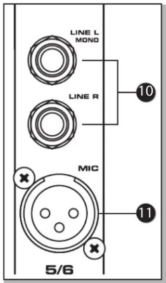
The XML610 and XML910 feature four stereo input strips, which include channels 5/6, 7/8, 9/10 and 11/12. While these channels look very much like the mono channels, they have two inputs so they can accept a stereo signal. As an added bonus, these inputs also include a microphone input, which can be used in mono.
-
1/4" LINE Inputs Channels 5–12 (XML610 and XML910 only) - Use these pairs of unbalanced 1/4" inputs for connecting stereo line level sources. When connecting only to the LINE L/MONO input, the input signal will be sent at equal levels to Left and Right mix.
-
XLR MIC Input Channels 5-12 (XML610 and XML910 only) - Use these inputs to connect Low Impedance microphones and low-level signals from direct boxes. The MIC inputs also feature +48V phantom power, allowing you to use condenser microphones. You can use the 1/4" LINE inputs and XLR MIC inputs simultaneously, but the VOL control will adjust all inputs together.
Controls and Functions
24-Bit Digital Effects Section
The XML mixers feature built-in, 24-bit digital effects processors with 100 high-quality, studio grade effects like Delay, Chorus and Reverb. The following section describes the features of the powerful on-board digital effects section.
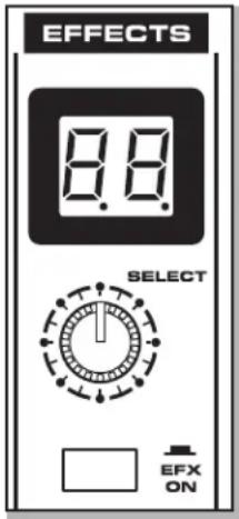
- Effects Program Display - The XML mixers' digital-effects processors feature dual-digit, seven-segment numerical display for showing the effects PROGRAM number from 00 - 99. You will see the PROGRAM numbers change as you scroll through the effects preset using the DSP SELECT control. When the Effects Display shows two straight lines through the center of each segment, the effects are turned off and the EFX ON switch is in the out position.
- Effects SELECT - The SELECT control knob is a continuously variable encoder, that allows you to call up one of the 100 built-in digital effects presets. Rotate the SELECT knob to scroll through the preset programs using the Effects Program Display to choose the number of the effect you want.
- Effects ON Switch - The Effects ON switch is used to turn the internal digital effects on and off. The effects are bypassed when the switch is in the out position and the Effects Display shows two dashes.
- Effects PROGRAM List - This section identifies the ten banks of built-in DSP effects presets. The first bank of ten presets is designed for live performance, and the subsequent banks are arranged in groups by the type of effect.
- Effects LEVEL Control - The Aux 2/EFX signals from input channels are mixed together and sent to the internal DSP and EFX 2 Output. The Effects LEVEL control is used to adjust the amount of signal send to the DSP and EFX 2 Output.
- EFX 2 Send Jack - The unbalanced 1/4" EFX 2 Send is used to route a signal to an external signal processor such as a delay or reverb. The signal present at the EFX 2 Send is routed from the EFX bus, which is fed from the input channel's Aux 2/EFX control knob.
- EFX FOOTSWITCH Jack - Connect a footswitch to the EFX FOOTSWITCH phone input jack to toggle the internal digital effects On and Off.


Controls and Functions
Main Section
The XML series mixers have two internal power amplifiers, depending on the power amp MODE selection switch, the amplifiers are sent the MAIN or MONITOR bus signal.
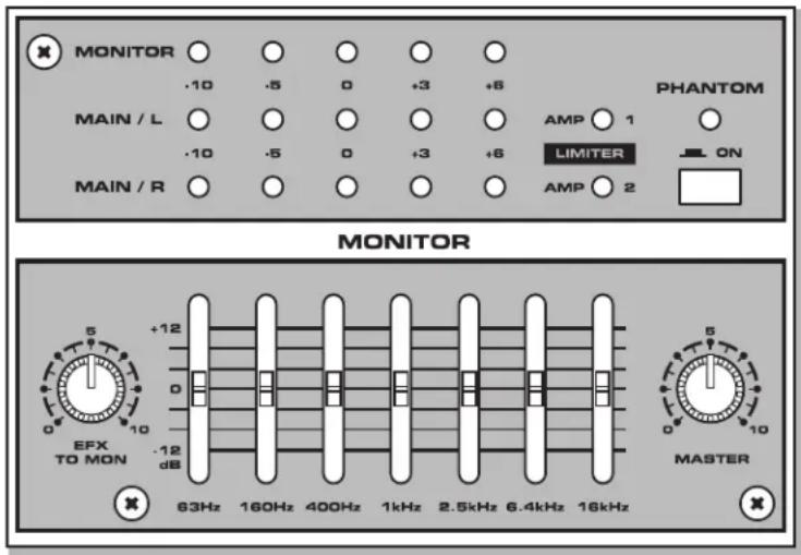
- MAIN Output Level Meters - The output level meter allows you to monitor the level of the signal being sent to the MAIN power amplifier and to the MAIN OUT jacks. To avoid distortion, adjust the MASTER LEVEL controls so that the 0 indicator LED lights occasionally.

- MONITOR Output Level Meter - The MONITOR
output level meter allows you to monitor the level of the signal which is being sent to the MONITOR send jack and MONITOR power amplifier.
- AMP 1/2 LIMITER - The LIMITER indicators light when the channel's signal for the corresponding amplifier hits its maximum value, and the limiter comes on. This will ensure the cleanest possible output, and will protect your speaker system if it accidentally receives a clipped signal from your mixer.
NOTE: If the LIMITER indicators are lighting frequently, there could be a risk of damage to your equipment. Turn the MASTER control counterclockwise until the indicator does not light during normal use.
- PHANTOM Power Switch - The XML mixers feature onboard, 48-Volt Phantom power supply to operate condenser microphones. When the switch is engaged, the LED will illuminate indicating that phantom power is now available on the microphone pre-amps.
IMPORTANT NOTE: To avoid a loud pop, be sure to turn down the MASTER level controls before plugging and unplugging the mic cables when the phantom power is active.
- EFX TO MAIN - The EFX TO MAIN control is used to adjust the level of the sound being sent back from the built-in digital effect to the MAIN mix bus. This allows you to hear the DSP effects in your MAIN speakers.

- Graphic Equalizer - The 7-band Graphic Equalizer allows you to contour the frequency response of the MAIN/MONO mix bus signal, providing a maximum of 12dB of cut/boost for each frequency band. This is an especially useful tool for cutting frequencies that cause annoying feedback. The frequency response is flat when the sliders are in the center position. Moving a slider in the positive direction will boost that frequency by as much as

12dB, and moving the slider in the negative direction will cut that frequency by up to 12dB. Once you set a response curve using the Graphic Equalizer, the EQ curve is applied to both the MAIN/MONO bus signal that is output to the speakers, and the line level signal which is output from the MAIN OUT jacks.
- MASTER - The MASTER level control is the overall volume control for the MAIN bus. The MAIN level affects both the MAIN bus signal, which is output to the speakers, and the line level signal which is output from the MAIN OUT jacks.

- EFX TO MON - The EFX TO MON control is used to adjust the level of the sound being sent back from the built-in digital effect to the MONITOR bus. This allows you to hear the DSP effects in your monitor speakers.
- Graphic Equalizer (XML610 and XML910 Only) - The 7-band Graphic Equalizer allows you to contour the frequency response of the MONITOR bus signal, providing a maximum of 12dB of cut/boost for each frequency band. This is an especially useful tool for cutting frequencies that cause annoying feedback. The frequency response is flat when the sliders are in the center position. Moving a slider in the positive direction will boost that frequency by as much as 12dB, and moving the slider in the negative direction will cut that frequency by up to 12dB. Once you set a frequency response curve using the Graphic Equalizer, the EQ curve is applied to both the MONITOR bus signal that is sent to the monitor speakers, and the line level signal which is sent from the MONITOR output jack.
- MASTER - The MASTER level control is the overall control for the MONITOR bus. The MONITOR level affects both the MONITOR bus signal which is sent to the monitor speakers and the line level signal which is sent from the MONITOR output jack.
Controls and Functions
External Input Jacks (AUX IN and CD/TAPE IN)
These input jacks allow the signal from an external device to be added to the MAIN output.
- AUX IN (XML410 Only) - This input jack allows the signal from an external device to be added to the MAIN output.

-
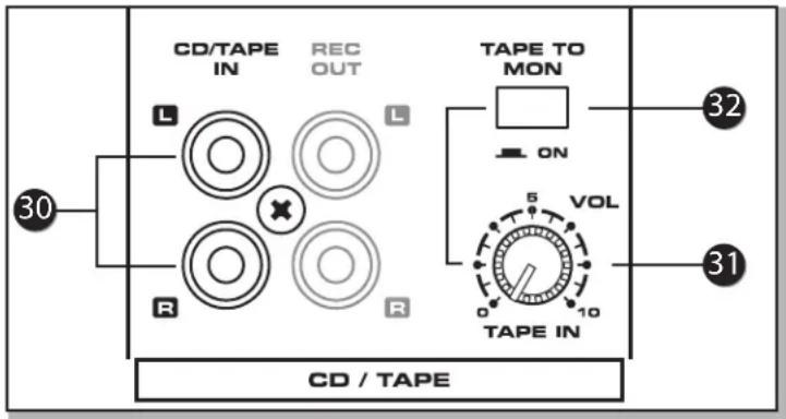
CD/TAPE IN - Use this stereo RCA input to connect a stereo output device such as an MP3 player or CD player to the mixer.
-
TAPE IN VOLUME - The TAPE IN VOLUME is used to set the level of the CD/TAPE IN jacks.
-
TAPE TO MON (XML610 and XML910 Only) - The TAPE TO MON switch allows you to add the CD/TAPE IN signal to the MONITOR bus. When you press this switch, the signal at the CD/TAPE IN is mixed in to the AUX 1/MON and the level is controlled by the TAPE IN VOLUME control.
NOTE: When the TAPE TO MON button is in the down position, the TAPE IN VOLUME control is used to adjust the amount of signal that is sent from the CD/TAPE IN jacks to the MONITOR bus.
Controls and Functions
External Output Jacks
The XML mixers feature several output connectors allowing you to interface a variety of external devices. A stereo recording device, such as a cassette recorder, can be connected to the REC OUT jacks, and additional power amplifiers can be connected to the MONITOR and MAIN output jacks.
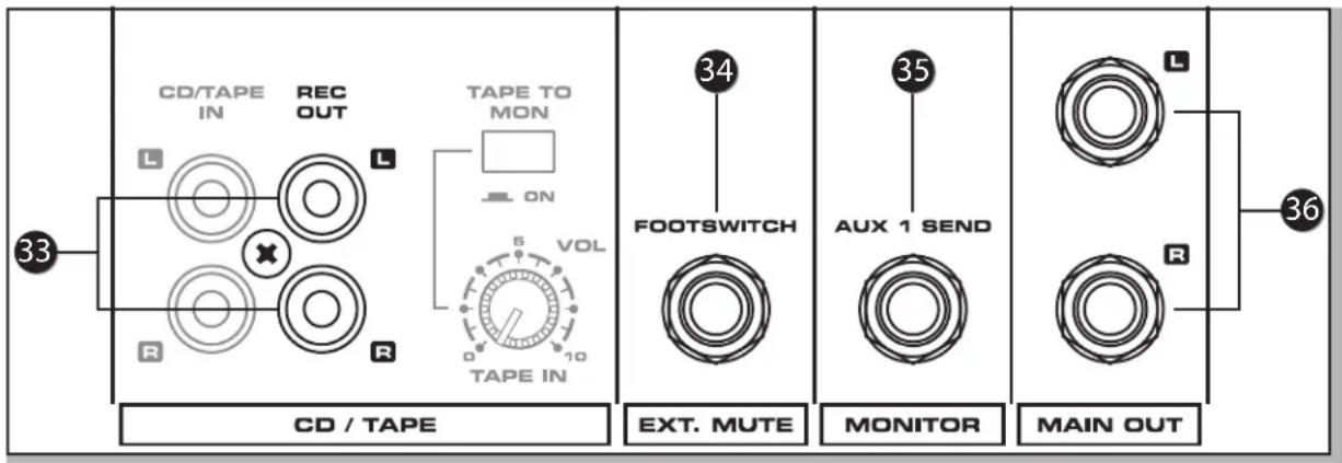
- REC OUT - The signal present at this stereo RCA connector is the MAIN bus signal before it has passed through the MASTER level control and graphic equalizer. The nominal output level is -10dBV and the impedance is 100 Ohms.
- EXT. MUTE (XML610 and XML910 Only) - Connect a footswitch to the EXT. MUTE phone input jack to turn off channels 1-8. This feature is convenient when connecting a microphone to CH 9/10 or 11/12 for making announcements and to use a footswitch to temporarily mute the music or input signals to CH 1-8.
- MONITOR - The MONITOR bus signal is present at this connector. The signal is passed through the MONITOR/MASTER level control and graphic equalizer (XML610 and XML910) before it reaches the MONITOR connector. In a live sound situation this can be used to create a monitor mix by connecting the MONITOR output to a power amp and monitor speaker.
- MAIN OUT (XML610 & XML910 Only) - The signals present at these connectors are the MAIN Left and Right bus signals, which have passed through the MAIN/MASTER level control and the graphic equalizer. The nominal output level is +4dBu and the impedance is 100 Ohms.
- MAIN OUT (XML410 Only) - The signal present at this connector are the MAIN bus signal, which have passed through the MAIN/MASTER level control and the graphic equalizer. The nominal output level is +4dBu and the impedance is 100K Ohms.

Controls and Functions
Power Amp Section
The XML series of mixers have a power amplifier section which can be configured to operate several ways depending on whether you need MAIN plus MONITOR amplifiers to power your speakers, or if you just need more power for the MAIN speakers. The section below describes the XML series' power amp modes.
-
POWER - The POWER indicator lights to indicate that the power in on.
-
Power Amp MODE switch - The MODE switch is used to select one of the following operating modes: MAIN-MONITOR, MAIN-MAIN or MAIN-BRIDGE (XML410 only).
CAUTION! Only change the power amp MODE switch when the power is SWITCHED OFF!
MAIN-MONITOR - With this setting, the MAIN and MONITOR sections can be used independently. The MAIN bus signal will be sent from the MAIN (XML410) or MAIN (L+R) (XML610 and XML910), and the MONITOR bus signal will be sent from the MONITOR jacks.
MAIN-MAIN - With this setting, the two power amp channels can be used independently. The MAIN bus signal will be output from the MAIN MODE (XML410) or RIGHT/LEFT jacks (XML610 and XML910 Rear Panel).

-
LOW ENHANCE (XML610 and XML910) - This switch turns on or off the LOW ENHANCE processing on and off. The LOW ENHANCE boosts the low frequencies at the speaker outputs. Use the LOW ENHANCE for added bass in situations where you do not have subwoofers.
-
MUTE CH 1–8 (XML610 and XML910) - You can turn off channels 1–8 on the XML610 or XML910 using the MUTE CH 1–8 switch. This feature is convenient to use when you take a break and want to leave all the levels set, so they are ready when you begin to use your PA system again. The MUTE 1–8 does not turn off channels 9/10, and 11/12, and does not turn off the CD/TAPE inputs.

Speaker Outputs - XML610 & XML910
The XML610 and XML910 powered mixers contain two mono power amplifiers and, depending on the operating mode, the two amplifiers can be used independently for LEFT and RIGHT MAIN outputs or for MONO MAIN + MONITOR outputs.
NOTE: Use the Power Amp MODE switch to select which signal is sent to the speaker output jacks.
The total impedance load for each amplifier must not exceed 4 Ohms, therefore, if you want to only connect a single speaker to each amp output, use a 4–8 Ohm speaker.
You can connect up to four speakers at one time. One speaker with an impedance of 8 Ohms can be connected to each of the amp's Speakon and 1/4" jacks. The Speakon and 1/4" jacks are wired in parallel, so the total impedance when two 8 Ohm speakers are connected is 4 Ohms.

- AMP 1 Speaker Outputs - The AMP 1 output has one Speakon and one 1/4" phone connector wired in parallel. These powered outputs can be used to connect your left side main PA speaker when using the XML610 or XML910 in MAIN/MAIN mode. When operating in MAIN/MONITOR mode, the AMP 1 powered output connectors are used to connect left and right side MAIN PA speakers.
- AMP 2 Speaker Outputs - The AMP 2 output has one Speakon and one 1/4" phone connector wired in parallel. These powered outputs can be used to connect your left side main PA speaker when using the XML610 or XML910 in MAIN/MAIN mode. When operating in MAIN/MONITOR mode, the AMP 2 powered output connectors are used to connect to floor or side fill monitors facing the performers.
Speaker Outputs - XML410
The XML410 contains two mono power amplifiers, and depending on the operating mode, the two amplifiers can be used independently (maximum output 200W + 200W) or in BRIDGE mode (maximum output 400W).
NOTE: Use the front panel Power Amp MODE switch to select which signal is sent to the speaker output jacks, and to activate BRIDGE mode.
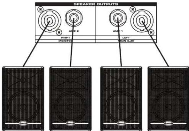
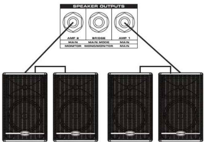
If the two power amplifiers are used for MAINS operation, two 8 Ohm speakers can be "daisy-chained" together and connected to the AMP 1 jack, and two more 8 Ohm speakers can be "daisy-chained" together and connected to the AMP 2 jack, for a total of four speakers.
The total impedance load for each amplifier must not exceed 4 Ohms. Therefore, in the example above, two speakers with an impedance of 8 Ohms each are connected to each amp's output jacks.
If you wish to use two amplifiers independently, let's say for Main and Monitor operation, use a 4–8 Ohm speaker. Again, the total impedance load for each amplifier must not exceed 4 Ohms. Therefore, two speakers with an impedance of 8 Ohms can be "daisy-chained" together and then connected to each amp's output jacks.
If two amplifiers are used in a BRIDGE mode, only one speaker can be connected to the BRIDGE jack. The total impedance load while operating in BRIDGE mode must not be less than 8 Ohms. If you are connecting a speaker to the BRIDGE jack, use an 8–16 Ohm speaker.
CAUTION: When using a BRIDGE connection, do not connect anything to the AMP 1 and AMP 2 jacks. Likewise, when using the AMP 1 and AMP 2 jacks, do not connect anything to the BRIDGE jack.

-
AMP 1 Speaker Outputs - The AMP 1 output has one 1/4" phone connector, which is a powered output used to connect your main PA speaker when using the XML410 in MAIN/MAIN mode. When operating in MAIN/MONITOR mode, the AMP 1 powered output connectors are used to connect left and right side MAIN PA speakers.
-
AMP 2 Speaker Outputs - The AMP 2 output has one 1/4" phone connector, which is a powered output used to connect your main PA speaker when using the XML410 in MAIN/MAIN mode. When operating in MAIN/MONITOR mode, the AMP 2 powered output connectors are used to connect to floor or side fill monitors facing the performers.
-
BRIDGE Output connector - The BRIDGE output has one 1/4" phone connector, which is a powered output used to connect one main PA speaker when using the XM410 in BRIDGE mode.
XML Series Rear Panel
- VOLTAGE SELECTION Switch - This switch is used to select the amplifier's operating voltage.
NOTE: If you are changing the position of this switch, be sure it is set to the correct voltage for your country, and that the correct fuse is installed.
- Fuse Cover - The fuse is located behind the fuse cover. Always replace fuses with the same type of fuse.
- POWER Switch - This is the primary power switch. When set to the ON position, the front panel POWER LED illuminates, indicating the XML mixer is powered up and ready for operation.
- AC INPUT - Connect the supplied IEC power cable here.

Speaker Connection - XML610 & XML910
The XML610 and XML910's power amplifier section can be configured to operate several ways depending on the setting of the Power Amp MODE switch located on the front panel. This allows you to choose whether you need MAIN plus MONITOR amplifiers to power your speakers, or if you just need more power for the MAIN speakers.
There are two ways in which speakers can be connected to the XML power mixer:
1) A single speaker can be connected to either the A or B jack of AMP 1 and AMP 2, or
2) Two speakers can be connected in parallel to both the A and B jacks of AMP1 and AMP 2.
For both of these situations, the required speaker impedance will differ. Refer to the following diagram, and make sure that the speaker impedance is not less than the specified value.

When connecting one speaker to AMP1 and one speaker to AMP 2, use speakers with a 4–8 Ohm impedance rating.
When connecting two speakers to AMP 1 and two speaker to AMP 2, use speakers with an 8–16 Ohm impedance rating.
Additional, or alternative amplifiers can be connected to the MAIN OUT and MONITOR output jacks on the front panel.
Neutrik NL4 Speakon Wiring

Speaker Connection - XML410
The XML410's power amplifier section can be configured to operate several ways, depending on the setting of the power amp MODE switch located on the front panel. This allows you to choose whether you need MAIN plus MONITOR amplifiers to power your speakers, or if you just need more power for the MAIN speakers.
There are three ways in which speakers can be connected to the XML410:
1) A single speaker can be connected to the output jack of AMP 1 and AMP 2,
2) Two speakers can be connected in parallel to the output jacks of AMP1 and AMP 2, or
3) A single speaker can be connected to the BRIDGE jack (bridge connection). For each of these situations, the required speaker impedance will differ.
Refer to the following diagram, and make sure that the speaker impedance is not less than the specified value.

When connecting one speaker to AMP1 and one speaker to AMP 2, use speakers with a 4–8 Ohm impedance rating.
flowchart
graph TD
    A["SPEAKER OUTPUTS"] --> B["AMP 2"]
    A --> C["BRIDGE"]
    A --> D["AMP 1"]
    B --> E["MONITOR"]
    C --> F["MONO/MONITOR"]
    D --> G["MAIN"]
    E --> H["Output Panel"]
    F --> I["Output Panel"]
    G --> J["Output Panel"]
When connecting two speakers to AMP 1 and two speaker to AMP 2, use speakers with an 8–16 Ohm impedance rating.

When the POWER AMPS are in BRIDGE mode, use a speaker with an 8–16 Ohm impedance rating.
Additional, or alternative amplifiers can be connected to the MAIN OUT and MONITOR OUT jacks on the front panel.
Basic Operation
Connecting Microphones and Instruments
The following section explains the basic operation of the XML series mixers.

Vocal Vocal Electric Guitar Bass Guitar Keyboards
-
Before connecting mics or instruments, make sure that the power of all your system components, including the XML mixer, is turned off. Also, make sure that the volume and gain controls of each channel of the XML mixer and the MAS-TER controls of the MAIN and MONITOR section are turned all the way down.
-
Connect the cables to your microphone(s) and instrument(s), and insert the other end of the cable firmly into each appropriate input on the XML mixer.
-
Switch on the power of any peripheral devices, and then power up the XML mixer.
NOTE: Since the XML mixers contains two power amplifiers, it is important to remember the Golden Rule of audio ... "LAST ON, FIRST OFF." This means that when turning on your system, you should always turn your power amplifiers on LAST, and when turning your system off, turn your power amps off FIRST. This helps avoid any loud pops caused by rush current at power up or power down, which can sometimes damage loudspeakers.
-
Set the MASTER control of the MAIN section to the "5" position.
-
While speaking into the mic (or playing the instrument), adjust the channel GAIN control so that the "PEAK" LED of the channel lights occasionally, then back it down slightly.
-
Slowly adjust the channel VOLUME control until the desired level is reached.
-
If you wish to adjust the tone of each channel, adjust the equalizer controls as desired. You may have to readjust the channel volume.
-
Use the MAIN section graphic equalizer and MASTER control to adjust the overall volume and tone.
Using the Internal Digital Effects
The XML series of mixers features built-in, high quality, 24-Bit Digital Signal Processors (DSP), offering studio grade effects. The DSP features clean Delay, lush Reverb and multi-effects like Chorus + Delay or Chorus + Reverb. You can also add a broad range of studio quality effects by simply dialing through the 100 presets. The following details the operation of the internal DSP effects:
- Connect a mic or instrument to the desired channel and adjust the volume and equalizer to your liking.
- Select the desired preset using the EFFECTS SELECT switch. Set the DSP SELECT switch to one of the following 100 effects:
0–9 Performance
10–19 Hall Reverb
20–29 Plate Reverb
30–39 Spring Reverb
40–49 Echo
50–59 Flange + Verb
60–69 Chorus + Verb
70–79 Echo + Verb
80–89 Chorus
90–99 Flange
- Once you have selected the desired effect preset, raise the AUX 2 EFX control on the channels you wish to apply the digital effect to.
- Use the EFX to MAIN/MON knob in the MAIN/MONITOR section to adjust the EFFECTS Return level. The EFX to MAIN/MON control is the overall level control for the DSP effects processor. If you are not using the mixer in MAIN/MONITOR or BRIDGE mode, be sure to raise the EFX to MAIN/MON control on both the MAIN and MAIN/MONITOR sections so the level of effect is the same in both speakers.
NOTE: If the effect sound is distorted even though the EFX to MAIN/MON is turned down, lower the AUX 2/EFX controls of each channel until you no longer hear distortion.
Creating a Monitor Mix
Sending an Independent Mix to Monitor Speakers
The XML series mixers allow you to operate the power amplifiers in a MAIN/MONITOR mode. This lets you use one amplifier for speakers facing the audience, and the other amplifier for the monitor speaker facing the musicians. Follow the steps below to create an independent mix for the mount or speakers.
- Set the channel MONITOR section and VOLUME control to the "0" position.
- Raise the AUX 1/MON controls for the channels that you wish to hear from the monitor speakers.
NOTE: The MONITOR controls are not affected by the level settings of each channel. This allows you to create a mix for the monitors that is independent of the MAIN mix.
- Use the graphic equalizer (XML610 and XML910 only) and MASTER controls of the MONITOR sections to adjust the overall volume and tone.
Using an External Effect
Sending an Independent Mix to an External Effects Processor
If you prefer to use an external device for effects processing, you can easily connect the unit using the XML EFX bus. Follow the steps below to interface your processor.

- Set the MONITOR section MASTER control to the "0" position. Press the EFX BYPASS switch to disable the internal DSP.
- Raise the AUX 2/EFX controls for the channels to which you want the external effect to be applied.
- Adjust the EFX LEVEL to the "5" position.
- Set the input level of the external effect so that the sound is not distorted, and so that the effect's input meter does not indicate a clipped signal.
- Connect the output of the external effect to an available input channel. Be sure to turn the AUX 2/EFX control for that channel all the way down. Use the channel's VOLUME control to adjust the effect return level.
CD/TAPE IN • REC OUT
Playing Back a CD
The XML mixers have a dedicated input for playing back a CD, Tape or MP3 player. To use the CD/TAPE INPUT, follow the steps below.
- Turn the TAPE IN VOLUME control and the MASTER level control all the way down.
- Follow the "LAST ON, FIRST OFF" rule by turning on your peripheral devices and then turning on the power on the XML mixer.
- Adjust the MASTER control of the MAIN section to the "5" position.
- Start playback on the CD, Tape or MP3 player. Use the TAPE IN VOLUME control to adjust the level so that the zero LED of the MAIN section peak level meter lights only occasionally. Adjust the master volume control to raise the level, if necessary.
Recording From the XML Mixer
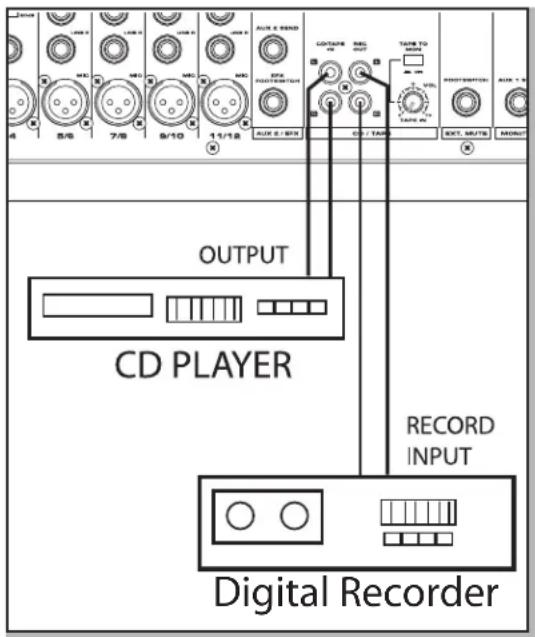
You can record the audio from the XML's mixer section including the MIC, LINE, TAPE IN and AUX inputs to a digital recorder, DAW, DAT or any other type of recorder using the RECORD outputs. Simply connect the mixer's REC OUT to the input jacks of the recorder, as shown in the diagram above.
XML System Setups

flowchart
graph TD
    A["CAMSON"] -->|Signal Flow| B["XML610/910's power amp operating in MAIN/MAIN mode"]
    B --> C["MONITOR OUT is connected to an external power amp"]
    C --> D["Main STEREO"]
    D --> E["MOD POWERED MIXER"]
    E --> F["XML 310"]
    F --> G["AMP 2 Output AMP 1 Output"]
    G --> H["XML MONITOR OUT connected to an external monitor amp"]
    H --> I["Signal Flow"]
    I --> J["Vocal Vocal Electric Guitar Bass Guitar Keyboards"]
    J --> K["Signal Processor"]
    K --> L["Radio"]
    L --> M["Direct Box"]
    M --> N["5/6"]
    N --> O["7/8"]
    O --> P["9/10"]
    P --> Q["11/12"]
    Q --> R["OUT 1/2"]
    R --> S["OUT 2/4"]
    S --> T["OUT 3/6"]
    T --> U["OUT 4/8"]
    U --> V["OUT 5/10"]
    V --> W["OUT 6/12"]
    W --> X["OUT 7/14"]
    X --> Y["OUT 8/16"]
    Y --> Z["OUT 9/18"]
    Z --> AA["OUT 10/20"]
    AA --> AB["OUT 11/22"]
    AB --> AC["OUT 12/24"]
    AC --> AD["OUT 13/26"]
    AD --> AE["OUT 14/28"]
    AE --> AF["OUT 15/30"]
    AF --> AG["OUT 16/32"]
    AG --> AH["OUT 17/34"]
    AH --> AI["OUT 18/36"]
    AI --> AJ["OUT 19/38"]
    AJ --> AK["OUT 20/40"]
    AK --> AL["OUT 21/42"]
    AL --> AM["OUT 22/44"]
    AM --> AN["OUT 23/46"]
    AN --> AO["OUT 24/48"]
    AO --> AP["OUT 25/50"]
XML System Setups

flowchart
graph TD
    A["Speaker 1"] --> B["Signal Flow"]
    B --> C["AMP 2 Output"]
    C --> D["Main Channel"]
    D --> E["Microphone Array"]
    E --> F["Output to mixer's line inputs"]
    F --> G["Vocal Vocal Electric Guitar Bass Guitar Keyboards"]
    G --> H["Signal Processor"]
    H --> I["Direct Box"]
    I --> J["Main Channel"]
    J --> K["AMP 2 Output"]
    K --> L["Signal Flow"]
    L --> M["AMP 2 Output"]
    M --> N["Main Channel"]
    N --> O["Microphone Array"]
    O --> P["Output to mixer's line inputs"]
    P --> Q["Vocal Vocal Electric Guitar Bass Guitar Keyboards"]
XML Wiring Guide
Connecting the XML Mixers
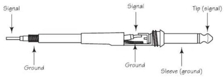
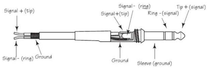
The are several ways to interface the XML mixers to support a variety of applications. The XML mixers feature balanced inputs and outputs, so connecting balanced and unbalanced signals is possible.
Unbalanced 1/4" Connector
Balanced TRS 1/4" Connector
XLR Balanced Wiring Guide


XML610 & XML910 Specifications
Rated Output power XML610: 2 x 300W at 4Ω @0.1% THD at 1KHz
XML910: 2 x 450W at 4Ω @0.1% THD at 1KHz
Frequency response 20Hz\~20KHz+/-0.7dB@1W Output into 8Ω (AMP OUT)
20 Hz\~20KHz+/-0.4@+4dB Output into 10kΩ (MAIN OUT, MONITOR
OUT, AUX 2 SEND)
Total Harmonic Distortion Less than 0.06%@20Hz\~20KHz, 150W output into4Ω (AMP OUT)
Less than 0.1%@20 Hz\~20KHz+14dB output into 10KΩ
(MAIN OUT, MON OUT, AUX 2 SEND)
HUM & Noise -112dB equivalent input noise
(Average, RS+150Ω) -95dB residual output noise (MAIN OUT, MONITOR OUT, AUX 2 OUT)
(with 22Hz\~22KHz BPF) -79dB (MAIN OUT, MONITOR OUT) Master level control at maximum,
all channel level control at minimum
-79dB (AUX 2) Master level control at maximum, all channel level con-
trols at minimum
Maximum Voltage Gain 36dB CH IN (MIC,XLR) to MAIN OUT, MONITOR OUT
42dB CH IN (MIC) to AUX 2 OUT
18.2dB CH IN (MIC) to REC OUT
26dB MONO CH IN (LINE) to MAIN OUT, MONITOR OUT
16dB ST CH IN (LINE) to MAIN OUT, MONITOR OUT
26dB AUX IN to MAIN OUT
30dB TAPE IN to MAIN OUT
Crosstalk 1KHz 70dB adjacent input, 70dB input to output
Input Channel Equalization HIGH 12KHz shelving (+/- 15dB Maximum)
MID 2.5KHz peaking (+/- 12dB Maximum)
LOW 80Hz shelving (+/- 15dB Maximum)
Meters 5 POINT LED METERS (-10, -5, 0, +3, +6dB)
Graphic Equalizer
7 bands (63, 160, 400, 1K, 2.5K, 6.4K, 16KHz)
Internal DSP Effects
24 BIT - 10 Presets each: 1 - Performance; 2 - Hall Reverb, 3 - Plate
Reverb; 4 - Spring Reverb; 5 - Echo; 6 - Flange + Verb;
7 - Chorus + Verb; 8 - Echo + Verb; 9- Chorus; 10- Flange
Phantom Power +48V
CLIP Indicators
Turn on: THD> 0.5%
Foot Switch
DIGITAL EFFECT MUTE: ON/OFF
GENERAL
Power Requirement
100V-240V, 50/60Hz
Power Consumption
XML610: 800W, full power
XML910: 1250W, full power
Weight
XML610: 14.5 lbs/6.5Kg
XML910: 15 lbs/6.8Kg
Dimensions
17.25" (W) x 11.65" (H) x 9.85" (D)
438mm(W) x 296mm(H) x 250mm(D)
Specifications subject to change without notice
XML410 Specifications
Rated Output power XML410: 2 x 200W at 4Ω @0.1% THD at 1KHz
Frequency response 20Hz\~20KHz+/-0.5dB@1W Output into 8Ω (AMP OUT)
20 Hz\~20KHz+/-0.4@+4dB Output into 10kΩ (MAIN OUT, MONITOR
OUT, AUX 2 SEND)
Total Harmonic Distortion Less than 0.06%@20Hz\~20KHz, 75W output into4Ω (AMP OUT)
Less than 0.1%@20 Hz\~20KHz+14dB output into 10KΩ
(MAIN OUT, MON OUT, AUX 2 SEND)
HUM & Noise -112dB equivalent input noise
(Average, RS+150Ω) -100dB residual output noise (MAIN OUT, MONITOR OUT, AUX 2 OUT)
(with 22Hz\~22KHz BPF) -79dB (MAIN OUT, MONITOR OUT) Master level control at maximum, all channel level control at minimum
-79dB (AUX 2) Master level control at maximum, all channel level con-
trols at minimum
Maximum Voltage Gain 36dB CH IN (MIC) to MAIN OUT, MONITOR OUT
42dB CH IN (MIC) to AUX 2 OUT
18.2dB CH IN (MIC) to REC OUT
16dB CH IN (LINE) to MAIN OUT, MONITOR OUT
26dB AUX IN to MAIN OUT
24dB TAPE IN to MAIN OUT
Crosstalk 1KHz 70dB adjacent input, 70dB input to output
Input Channel Equalization HIGH 12KHz shelving (+/- 15dB Maximum)
MID 2.5KHz peaking (+/- 12dB Maximum)
LOW 80Hz shelving (+/- 15dB Maximum)
Meters 5 POINT LED METERS (-10, -5, 0, +3, +6dB)
Graphic Equalizer 7 bands (63, 160, 400, 1K, 2.5K, 6.4K, 16KHz)
Internal DSP Effects 24 BIT - 10 Presets each: 1 - Performance; 2 - Hall Reverb, 3 - Plate
Reverb; 4 - Spring Reverb; 5 - Echo; 6 - Flange + Verb; 7 -
Chorus + Verb; 8 - Echo + Verb; 9- Chorus; 10- Flange
Phantom Power +48V
CLIP Indicators Turn on: THD> 0.5%
Foot Switch DIGITAL EFFECT MUTE: ON/OFF
GENERAL
Power Requirement 100V-240V, 50/60Hz
Power Consumption 600W, full power
Weight 13.7 lbs/6.2Kg
Dimensions 17.25" (W) x 11.65" (H) x 9.85" (D)
438mm(W) x 296mm(H) x 250mm(D)
Specifications subject to change without notice
XML610 & XML910 Block Diagram
XML610/910 BLOCK DIAGRAM

flowchart
graph TD
    subgraph Power Supply
        A["INPUT A [15kV/Hz"]] --> B["TRANSITOM"]
        B --> C["3-Stage EQ"]
        C --> D["FA"]
        D --> E["7-Stage GEQ"]
        E --> F["BA"]
        F --> G["INV"]
        G --> H["L"]
        H --> I["MAIN OUT [-4.6Vz"]]
        J["MAC [20kVz"]] --> K["HA"]
        K --> L["SUM"]
        L --> M["3-Stage EQ"]
        M --> N["FA"]
        N --> O["7-Stage GEQ"]
        O --> P["BA"]
        P --> Q["INV"]
        Q --> R["L"]
        R --> S["MAIN OUT [-4.6Vz"]]
        T["CLK INPUT [CHIKKON"]] --> U["SUM"]
        U --> V["3-Stage EQ"]
        V --> W["FA"]
        W --> X["7-Stage GEQ"]
        X --> Y["BA"]
        Y --> Z["INV"]
        Z --> AA["L"]
        AA --> AB["MAIN OUT [-4.6Vz"]]
        AC["LINE L/MONO [pH"] --> AD]
        AD --> AE["SUM"]
        AE --> AF["3-Stage EQ"]
        AF --> AG["FA"]
        AG --> AH["7-Stage GEQ"]
        AH --> AI["BA"]
        AI --> AJ["INV"]
        AJ --> AK["L"]
        AK --> AL["MAIN OUT [-4.6Vz"]]
        AM["LNE R [pH"] --> AN]
        AN --> AO["SUM"]
        AO --> AP["3-Stage EQ"]
        AP --> AQ["FA"]
        AQ --> AR["7-Stage GEQ"]
        AR --> AS["BA"]
        AS --> AT["INV"]
        AT --> AU["L"]
        AU --> AV["MAIN OUT [-4.6Vz"]]
        AW["MAC [20kVz"]] --> AX["SUM"]
        AX --> AY["3-Stage EQ"]
        AY --> AZ["FA"]
        AZ --> BA["7-Stage GEQ"]
        BA --> BB["BA"]
        BB --> BC["INV"]
        BC --> BD["L"]
        BD --> BE["MAIN OUT [-4.6Vz"]]
        BF["LNE R [pH"] --> BG] --> BH["SUM"]
        BH --> BI["3-Stage EQ"]
        BI --> BJ["FA"]
        BJ --> BK["7-Stage GEQ"]
        BK --> BL["BA"]
        BL --> BM["INV"]
        BM --> BN["L"]
        BN --> BO["MAIN OUT [-4.6Vz"]]
        BP["MIC [20kVz"]] --> BQ["VA"]
        BQ --> BR["SUM"]
        BR --> BS["3-Stage EQ"]
        BS --> BT["FA"]
        BT --> BU["7-Stage GEQ"]
        BU --> BV["BA"]
        BV --> BW["INV"]
        BW --> BX["L"]
        BX --> BY["MAIN OUT [-4.6Vz"]]
        BZ["CN RPT [PWR"] --> CA["PWM"]
        CA --> CB["PWM"]
        CB --> CC["PWM"]
        CC --> CD["PWM"]
    end

    subgraph Power Supply
        E
        F
        G
        H
        I
        J
    end

    subgraph Control
        K
        L
        M
    end

    subgraph Power Supply
        N
    end

    subgraph Control
        O
    end

    subgraph Power Supply
        P
    end

    subgraph Control
        Q
    end

    subgraph Control
        R
    end

    subgraph Control
        S
    end

    subgraph Control
        T
    end

    subgraph Control
        U
    end

    subgraph Control
        V
    end

    subgraph Control
        W
    end

    subgraph Control
        X
    end

    subgraph Control
        Y
    end

    subgraph Control
        Z
    end

    subgraph Control
        AA
    end

    subgraph Control
        AB
    end

    subgraph Control
        AC
    end

    subgraph Control
        AD
    end

    subgraph Control
        AE
    end

    subgraph Control
        AF
    end

    subgraph Control
        AG
    end

    subgraph Control
        AH
    end

    subgraph Control
        AI
    end

    subgraph Control
        AJ
    end

    subgraph Control
        AK
    end

    subgraph Control
        AL
    end

    subgraph Control
        AM
    end

    subgraph Control
        AN
    end

    subgraph Control
        AO
    end

    subgraph Control
        AP
    end

    subgraph Control
        AQ
    end

    subgraph Control
        AR
    end

    subgraph Control
        AS
    end

    subgraph Control
        AT
    end

    subgraph Control
        AU
    end

    subgraph Control
        AV
    end

    subgraph Control
        AW
    end

    subgraph Control
        AX
    end

    subgraph Control
        AY
    end

    subgraph Control
        AZ
    end

    subgraph Control
        BA
    end

    subgraph Control
        BB
    end

    subgraph Control
        BC
    end

    subgraph Control
        DA
    end

    subgraph Control
        EY
    end

    subgraph Control
        AFY
    end

    subgraph Control
        AGY
    end

    subgraph Control
        AHY
    end

    subgraph Control
        AIY
    end

    subgraph Control
        AZY
    end

    subgraph Control
        AYX
    end

    subgraph Control
        AZXY
    end

    subgraph Control
        BAIXY
    end

    subgraph Control
        AYA1A1A1A1A1A1A1A1A1A1A1A1A1A1A1A1A1A1A1A1A1A1A1A1A1A1A1A1A1A1A1A1A1A1A1A1A1A1A1A1A1A1A1A1A1A1A1A1A1A1A1B0E0000000000000000000000000000000000000000000000000000000000000000000000000000000000000000000000000000CFFOUTOUTFOOTSWI
XML410 Block Diagram
XML410 BLOCK DIAGRAM

flowchart
graph TD
    subgraph CH1-6
        A["MC"] --> B["FNUTON"]
        B --> C["FAE"]
        C --> D["204B PAD"]
        D --> E["LIVE"]
        E --> F["LOW HIGH"]
        F --> G["AUX/DFX"]
        G --> H["AUX/MON"]
    end

    subgraph TAPE INPUT
        I["VOLUME"] --> J["VOLUME"]
        J --> K["TAPE INPUT"]
        L["VOLUME"] --> M["VOLUME"]
        M --> N["AUX INPUT"]
    end

    subgraph AUX INPUT
        O["VOLUME"] --> P["VOLUME"]
        P --> Q["TAPE INPUT"]
        R["VOLUME"] --> S["VOLUME"]
        S --> T["AUX INPUT"]
    end

    subgraph FOOT SW
        U["DCP 100 PRESET"]
        V["SELECT"]
        W["FX ON"]
        X["FX RETURN"]
        Y["FX RETURN"]
        Z["FX RETURN"]
    end

    subgraph TIME_COU
        AA["L"] --> AB["R"]
        AC["L"] --> AD["REC OUT"]
        AE["MASTER"] --> AF["TONE ICU"]
        AG["MASTER"] --> AH["POWER AMP 1"]
        AI["MONITOR"] --> AJ["BRIDGE"]
        AK["MONITOR OUT"] --> AL["AUX2 SEND"]
    end

    subgraph MAIN_OUT
        AM["CLIP 2.5V 1.0"] --> AN["FAE LIMITED"]
        AO["CLIP 2.5V 1.0"] --> AP["FEAR LIMITED"]
        AQ["FRIC LTR"] --> AR["FAE LIMITED"]
        AS["FRIC LTR"] --> AT["FAE LIMITED"]
    end

    subgraph POWER_AMP 1
        AU["A"] --> AV["Bridge"]
        AW["A"] --> AX["Bridge"]
        AY["A"] --> AZ["Bridge"]
    end

    subgraph POWER_AMP 2
        BA["A"] --> BB["Bridge"]
        BC["A"] --> BD["Bridge"]
    end
SAMSON®
45 Gilpin Avenue
Hauppauge, New York 11788-8816
Phone: 1-800-3-SAMSON (1-800-372-6766)
Fax: 631-784-2201
www.samsontech.com
- Important Safety Information
- AVIS RISQUE DE CHOC ÉLECTRONIQUE - NE PAS OUVRIR
- Table of Contents
- Introduction
- XML Features
- Controls and Functions
- Input Channel Section
- Stereo Channel Inputs
- 24-Bit Digital Effects Section
- Main Section
- External Input Jacks (AUX IN and CD/TAPE IN)
- External Output Jacks
- Power Amp Section
- Speaker Outputs - XML610 & XML910
- Speaker Outputs - XML410
- XML Series Rear Panel
- Speaker Connection - XML610 & XML910
- Speaker Connection - XML410
- Basic Operation
- Connecting Microphones and Instruments
- Using the Internal Digital Effects
- Creating a Monitor Mix
- Sending an Independent Mix to Monitor Speakers
- Using an External Effect
- Sending an Independent Mix to an External Effects Processor
- CD/TAPE IN • REC OUT
- Playing Back a CD
- Recording From the XML Mixer
- XML Wiring Guide
- Connecting the XML Mixers
- XML610 & XML910 Specifications
- XML410 Specifications
- GENERAL
- XML410 Block Diagram
- SAMSON®
Brand : SAMSON
Model : XML410
Category : Mixer