
PG3800 - Receiver SAMSON - Free user manual and instructions
Find the device manual for free PG3800 SAMSON in PDF.


| Product Type | Wireless Receiver |
| Brand | Samson |
| Model | PG3800 |
| Frequency Range | UHF 500-950 MHz (varies by region) |
| Number of Channels | Up to 100 preselectable frequencies |
| Audio Output | XLR balanced and 1/4" unbalanced |
| Antenna Type | Detachable BNC antennas (2 included) |
| Dimensions (W x H x D) | 19" x 1.75" x 8.5" (rackmount, 1U) |
| Weight | Approx. 5.5 lbs (2.5 kg) |
| Power Supply | 12V DC 600mA (external adapter) |
| Power Consumption | < 10W |
| Key Features | True diversity reception, auto-scan, IR sync, front-panel controls |
| Maintenance | Clean with dry cloth; avoid liquids; store in dry place |
| Safety | Use only supplied power adapter; do not expose to rain or moisture |
| Spare Parts & Repairability | Contact Samson support; authorized service centers only |
| General Information | Professional wireless receiver for stage and studio |
Frequently Asked Questions - PG3800 SAMSON
User questions about PG3800 SAMSON
0 question about this device. Answer the ones you know or ask your own.
Ask a new question about this device
Download the instructions for your Receiver in PDF format for free! Find your manual PG3800 - SAMSON and take your electronic device back in hand. On this page are published all the documents necessary for the use of your device. PG3800 by SAMSON.
USER MANUAL PG3800 SAMSON
TO PREVENT FIRE OR SHOCK HAZARD. DO NOT USE THIS PLUG WITH AN EXTENON CORD, RECEPTACLE OR OTHER OUTLET UNLESS THE BLADES CAN BE FULLY INSERTED TO PRESENT BLADE EXPOSURE. TO PREVENT FIRE OR SHOCK HAZARD. DO NOT EXPOSE THIS APPLIANCE TO RAIN OR MOISTURE. TO PRVENT ELECTRICAL SHOCK, MATCH WIDE BLADE PLUG TO WIDE SLOT FULLY INSERT.

This lightnig flash with arrowhead symbol, within an equilateral triangle, is intended to alert the user to the presence of uninsulated “dangerous voltage” within the product’s enclosure that may be sufficient magnitude to constitute a risk of electric shock to persons.
CAUTION
RISK OF ELECTRIC SHOCK DO NOT OPEN
Warning: To reduce the risk of electric shock, do not rem cover (or back) no user serviceable parts inside. Refer serving to qualified service personnel.

The exclamation point within an equilateral triangle is intended to alert the user to the presence of important operating and maintenance (servicing) instructions in the literature accompanying the appliance.
IMPORTANT SAFETY INSTRUCTIONS
- Read these instructions.
- Keep these instructions.
- Heed all warnings.
- Follow all instructions.
- Do not use this apparatus near water.
- Clean only with dry cloth.
- Do not block any ventilation openings. Install in accordance with the manufacture's instructions.
- Do not install near any heat sources such as radiators, heat registers, stoves, (including amplifiers) that produce heat.
- Do not defeat the safety purpose of the polarized or grounding type plug. A polarized plug blades with one wider than the other. A grounding type plug has two blades and a third grounding prong. The wide blade or the third prong are provided for your safety. If the provided plug does not fit into your outlet, consult an electrician for replacement of the obsolete outlet.
- Protest the power cord from being walked on or pinched particularly at the plugs, convenience receptacles, and at the point where they exit from the apparatus.
- Only use attachments/accessories specified by the manufacturer.
- Use only with the cart, stand, tripod, bracket, or table specified by the manufacturer, or sold with the apparatus. When a cart is used, moving the cart/apparatus combination to avoid injury from tip-over.
- Unplug the apparatus during lightening sort or when unused for long periods of time. Refer all servicing to qualified personnel. Serving is required when the apparatus has been damaged in any way, such as power supply cord or plug is damaged, liquid has been spilled or objects have fallen into the apparatus has been exposed to rain or moisture, does not operate r
- dropped. This appliance shall not be exposed to dripping or splashing water and that no object filled with liquid
- such as vases shall be placed on the apparatus.
- Caution-to prevent electrical shock, match wide blade plug wide slot fully insert.
- Please keep a good ventilation environment around the entire unit.

Safety Instructions/Consignes de sécurité/Sicherheitsvorkehrungen/Instrucciones de seguridad
WARNING
DO NOT EXPOSE THIS EQUIPMENT
TO RAIN OR MOISTURE
AVIS
RISQUE DE CHOC ELECTRONIQUE
NE PAS OUVRIR
CAUTION
FOR CONTINUED PROTECTION AGAINST RISK
OF FIRE, REPLACE ONLY WITH SAME TYPE FUSE
ATTENTION
UTILISER UN FUSIBLE DE
RECHANGE DE MÊME TYPE

CAUTION
RISK OF ELECTRIC SHOCK DO NOT OPEN

WARNING: To reduce the risk of fire or electric shock, do not expose this unit to rain or moisture. To reduce the hazard of electrical shock, do not remove cover or back. No user serviceable parts inside. Please refer all servicing to qualified personnel. The lightning flash with an arrowhead symbol within an equilateral triangle, is intended to alert the user to the presence of uninsulated "dangerous voltage" within the products enclosure that may be of sufficient magnitude to constitute a risk of electric shock to persons. The exclamation point within an equilateral triangle is intended to alert the user to the presence of important operating and maintenance (servicing) instructions in the literature accompanying the product.
Important Safety Instructions
- Please read all instructions before operating the unit.
- Keep these instructions for future reference.
- Please heed all safety warnings.
- Follow manufacturers instructions.
- Do not use this unit near water or moisture.
- Clean only with a damp cloth.
- Do not block any of the ventilation openings. Install in accordance with the manufacturers instructions.
- Do not install near any heat sources such as radiators, heat registers, stoves, or other apparatus (including amplifiers) that produce heat.
- Do not defeat the safety purpose of the polarized or grounding-type plug. A polarized plug has two blades with one wider than the other. A grounding type plug has two blades and a third grounding prong. The wide blade or third prong is provided for your safety. When the provided plug does not fit your outlet, consult an electrician for replacement of the obsolete outlet.
- Protect the power cord from being walked on and pinched particularly at plugs, convenience receptacles and at the point at which they exit from the unit.
- Unplug this unit during lightning storms or when unused for long periods of time.
- Refer all servicing to qualified personnel. Servicing is required when the unit has been damaged in any way, such as power supply cord or plug damage, or if liquid has been spilled or objects have fallen into the unit, the unit has been exposed to rain or moisture, does not operate normally, or has been dropped.
PG Series Features....2
Guided Tour - Front Panel 3
Guided Tour - Rear Panel....4
Setting Up and Using Your PG Series 5
Setting Up and Using Your PG Series 6
The PG Series Protection Circuitry 6
Bridge and Parallel Modes....7
PG Series Connections 8
PG Series Connections 9
Specifications.... 10
Copyright 2008, Samson Technologies Corp.
Printed October, 2008 v1.2
Samson Technologies Corp.
45 Gilpin Avenue
Hauppauge, New York 11788-8816
Phone: 1-800-3-SAMSON (1-800-372-6766)
Fax: 631-784-2201
www.samsontech.com
Introduction
Thank you for purchasing the PG2200 or PG 3800 power amplifier from Samson! We know you don't like reading owners manuals, but you've just purchased one of the finest sound reinforcement power amplifiers around, and we want to tell you about it! So, before you plug in, we'd like to suggest you take just a few moments out to scan these pages. We'll make it as painless as possible, we promise—and, who knows, you might just pick up a tip or two. The Samson PG Series stereo power amplifiers have been designed to a specification we call Pure Gain Amplification. The PG series amplifiers provide robust, clean output with low distortion and wide dynamic range, along with the dependability demanded by the most professional audio engineers and installers. This manual covers both the PG2200 and PG3800 models. The PG series convenient 2 rack-space design is compact, and yet there's plenty of power available, with 2 x 280 Watts at 8Ω, 2 x 500 Watts at 4Ω and 2 x 1000 Watts at 2Ω for the PG2200 and 2 x 560 Watts at 8Ω, 2 x 900 Watts at 4Ω and 2 x 1800 Watts at 2Ω for the PG3800. For mono applications, a Bridge mode links both channels of the amplifiers, thus providing even more power, with massive mono power ratings of 1000 watts at 8Ω, 2200 watts at 4Ω for the PG2200 and 1800 watts at 8Ω, 3800 watts at 4Ω for the PG3800. Making input connections is simple since the PG series' rear panel provides both balanced XLR and balanced 1/4-inch TRS connections. For the outputs, the PG Series amplifiers provide standard 5-way binding posts, as well as dual Speakon™ connectors. The front-panel controls and displays include a large power switch with LED indicator, as well as independent left and right channel input level controls. To help you set the correct operating levels, the PG series amplifiers include front panel Signal, Peak and Protection LED indicators. The PG series amplifiers also include onboard dynamics processing with a selectable Low Frequency Filter at 30 Hz to help remove stage rumble and a selectable Limiter to help protect your speakers and help keep your signal clean. Like all serious power amplifiers, the PG Series internal electronics are based around a serious power-core, with over-sized toroidal transformers and large extruded heat sinks. To keep the PG series amplifiers running cool, their designs employ twin internal wind tunnels with forced-air cooling via two temperature-sensitive, variable speed fans, which greatly reduces the chance of thermal and overheating problems. Multi-stage protection for power-up, over-heating, over-current, short circuit, low output impedance and DC voltage, assures high reliability under the most demanding situations. The PG series amps are road tough with their all steel chassis, 19-inch rack mount design and convenient carry handles, the PG series amplifiers are ready for a life of travel, or at home in a nice fixed installation. Optimized for live sound venues, houses of worship, commercial installations, and for driving small and medium-sized live PA systems, the PG series amplifiers will deliver reliable power from gig-to-gig and venue-to-venue, day in and night out.
With proper care and adequate air circulation, your PG Series amplifier will operate trouble free for many years. We recommend you record your serial number in the space provided below for future reference.
Serial number:
Date of purchase:
In these pages, you'll find a detailed description of the many features of the PG Series power amplifier, as well as a guided tour through its front and rear panels, step-by-step instructions for its setup and use, and full specifications. You'll also find a warranty card enclosed—please don't forget to fill it out and mail it in so that you can receive online technical support and so we can send you updated information about these and other Samson products in the future. Also, be sure to check out our website (www.samsontech.com) for complete information about our full product line.
SPECIAL NOTE: Should your PG Series ever require servicing, a Return Authorization number (RA) is necessary. Without this number, the unit will not be accepted. If purchased in the United States, please call Samson at 1-800-372-6766 for a Return Authorization number prior to shipping the unit. If purchased outside the United States, contact your local Samson dealer for details. Please retain the original packing materials and, if possible, return the unit in its original carton and packing materials. If you purchased your Samson product outside the United States, please contact your local distributor for warranty information and service.
PG Series Features

The Samson PG Series power amplifier utilizes the latest technology in professional power amplifier design. Here are some of its main features:
• Power to spare - Each amplifier delivers the following power ratings:
PG2200 2 x 280 Watts at 8Ω, 2 x 500 Watts at 4Ω and 2 x 1000 Watts at 2Ω PG3800 2 x 560 Watts at 8Ω, 2 x 900 Watts at 4Ω and 2 x 1800 Watts at 2Ω
- For mono applications, the amplifiers can operate in Bridge mode which links both channels providing even more power. Massive mono power ratings of 1000 watts at 8 and 2200 watts at 4 for the PG2200 and a 1800 watts at 8 and 3800 watts at 4 for the PG3800.
- Clean, crisp sound - Impressive audio specifications such as 0.04% THD, dynamic range of 105 dB, crosstalk of 80 dB, and frequency response of 5 Hz to 55 kHz guarantee ultra-clean sound quality.
- Independent input level controls for each channel allow precision adjustments.
- LED signal indicators for each channel continuously display power output levels and allow you to correct for overloading (clipping) conditions.
- In order to help keep the input signal clean, the PG series amplifiers have a selectable Limiter, which also helps protect the connected speakers.
- Both the PG2200 and PG3800 have a rear panel, selectable Low Frequency Filter at 30 Hz to help remove unwanted low frequency rumble.
- Unique stable bipolar circuit design that continuously keeps DC output during idling at or near zero volts (thus keeping idle speakers at their zero point). This serves to minimize heat overload problems by effectively preventing the PG Series from applying power when unnecessary.
- Forced air cooling via two temperature-sensitive, variable speed fans provides reliable performance without thermal and overheating problems.
- Protection relay circuitry that guards against overheating or faulty wiring conditions and also prevents "thumps" when powering on or off. This means that you can use the PG Series with a single power strip into which a mixer or other audio devices are connected, without danger of damage to connected speakers.
• Each channel provides both balanced XLR and balanced 1/4-inch TRS input connectors for easy connections. - Output connections are made via 5-way binding posts and Speakon™ connectors.
- Toroidal transformer power supply for high current and low profile.
- The PG Series can be mounted in any standard 19" rack (taking just two rack spaces), making it easy to integrate the amp into any fixed or traveling PA rig.
- Rugged construction (an all-steel chassis with a cool gray finish and a lightweight anodized aluminum heatsink) makes the PG Series eminently roadworthy.
- Extended three-year warranty.
- Last but certainly not least, value. The Samson PG Series has been designed from the ground up to deliver excellent yet affordable sound quality.
Guided Tour - Front Panel

1: Handle - For easy transport while carrying, or while rack mounting, the PG amplifier features two die-cast handles located conveniently on the left and right side of the front panel.
2: POWER switch - Use this to power the PG Series on or off. The internal LED lights whenever the PG Series is powered on.
3: Vent -The PG series amplifiers stay cool thanks to their twin, forced-air cooling tunnels. Cool air is drawn through the front panel vents, reducing the temperature of the internal components while forcing the heat out the rear vents. The fans will actually sense the internal temperature and adjust their speed to maintain the optimum cooling conditions.
4 VOLUME controls - These 42-position detented controls allow you to precisely adjust the input level of the signal arriving at the rear-panel input jacks (see #2 on the following page). At their fully counterclockwise position (labeled "MIN"), the signal is attenuated by 80 dB (essentially completely off). At their fully clockwise position (labeled "MAX"), the controls are at unity gain (that is, no attenuation). When +4 dBu of signal arrives at the input jacks and the Channel input level controls are set to their fully clockwise "MAX" position, the PG Series delivers full power output.
5: POWER LED - The front panel LED indicator will illuminate when the Power switch is set to the "ON" position.
6: PROTECT LED - This goes on for approximately five seconds whenever the PG Series is powered on and then turns off (you'll hear a "click" when it does so). The Protection LED will also light when overheating or other severe problems occur (see page 8 in this manual for more information). It is normal for the Protection LED to fade slowly when the amp is powered off. When lit, no signal is provided to any connected speakers, thus muting them and preventing any "thump" from occurring. For a complete description of the conditions under which this light goes on, see the section entitled "The PG Series Protection Circuitry" on page 8 of this manual.
7: CLIP LED - The CLIP segment lights whenever the channel is outputting signal at full strength. For the best signal-to-noise ratio, the (CLIP) segment should light occasionally during peak levels; if it lights frequently, you may be overloading the PG Series and a distorted ("clipped") signal is probably being output. If this occurs and backing off the Input Level control delivers too low an output level for your application, consider using Bridge mode (see the "Bridge and Parallel Modes" section on page 9 in this manual for more information).
8: SIGNAL LED - The front panel LED indicators continuously monitor the power output level for the corresponding channel. The SIGNAL LED lights whenever output signal is present
Guided Tour - Rear Panel

1: Fan - This variable-speed fan provides vital cooling to your PG Series (the hotter the amp gets, the faster the fan blows!). Make sure that both the front and rear panels are kept free of all obstructions and that cool, fresh air is accessible at all times. Also, try to ensure that the PG Series is used in a dust-free environment.
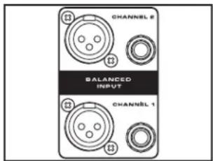
2: Input connectors - Connect incoming signals to these electronically balanced connectors, using either XLR or 1/4" TRS (Tip/Ring/Sleeve) plugs, wired as follows: Pin 2 (or Tip) hot, Pin 3 (or Ring) cold, and Pin 1 (or Sleeve) ground. We recommend the use of balanced three-conductor cabling wherever possible (unbalanced two-conductor 1/4" plugs can also be inserted into these inputs, but you'll get better signal quality and less outside noise and hum if you use balanced lines). The PG Series accepts input levels of any strength but needs at least +4 dBu to achieve maximum power. Stereo signals should be connected to both the Channel 1 and Channel 2 input jacks; however, when operating the PG Series in Bridge or Parallel modes, use the Channel 1 input jack only. See page 9 in this manual for more information about Parallel mode and pages 10 and 11 in this manual for full interconnection instructions.
3: Low Frequency Filter - This toggle switch is used to engage a low cut filter, 12 dB per octave at 30 Hz.
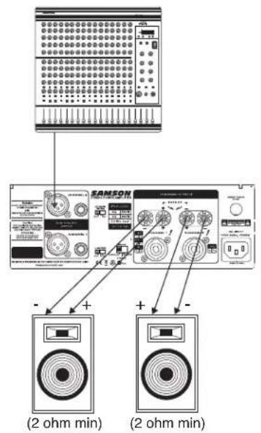
4: 5-way Binding Post - Use these to connect each channel of the PG Series to 4-ohm or 8-ohm loudspeakers. Be sure to connect the loudspeaker correctly, with the red (+) terminal normally connected to the positive input of the speaker and the black (ground) terminal normally connected to the negative input of the speaker. See page 9 in this manual for more information about Bridge mode and pages 10 and 11 in this manual for full speaker connection instructions.
5: Circuit Breaker - This circuit breaker will trip if there is a fault with the mains voltage or if maximum output is exceeded (very highly distorted). Push it in (once only!) to restart the amplifier after a short rest period.
6: AC input - Connect the supplied heavy-gauge 3-pin "IEC" power cable here.
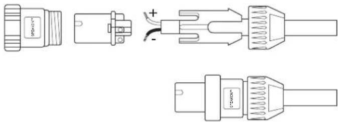
7: Speakon™ output connectors - Alternatively, you can use these to connect each channel of the PG Series to 4 or 8-ohm loudspeakers. See page 9 in this manual for more information about Bridge mode and pages 10 and 11 in this manual for full Speakon™ connector wiring and interconnection instructions.
8: Bridge / Stereo / Parallel switch - For normal operation, place this three-way switch in its center ("STEREO") position. When placed in its left ("PARALLEL") position, the signal arriving at the Channel 1 input only is routed to the power amplifiers of both Channel 1 and Channel 2 (the Channel 2 input is ignored). When placed in its right ("BRIDGE") position, the signal arriving at the Channel 1 input only is again routed to both power amplifiers (again, the Channel 2 input is ignored), but the two power amplifiers are bridged together. For more information, see the "Bridge and Parallel Modes" section on page 9 in this manual and the "PG Series Connections" section on pages 10 -11 in this manual. WARNING: Due to the extremely high power output of the PG Series when used in Bridge mode, be sure to use only loudspeakers sufficiently rated to handle the resultant wattage (in Bridge mode, these must be 4 or 8-ohm speakers).
9: Limiter - This toggle switch is used to engage the Limter circuit, an automatic dynamics processor used to hold the input signal at a fixed threshold level which helps keep a clean signal and protect the connected speakers.
Setting Up and Using Your PG Series

Bridge / Stereo / Parallel switch

Output connectors
Input connectors

Limiter

Low Frequency Filter

Channel Input control

Protection LED
Setting up your PG Series is a simple procedure which takes only a few minutes:
- Remove all packing materials (save them in case of need for future service) and decide where the amplifier is to be physically placed—it can be used free-standing or mounted in a standard 19" rack, requiring only two rack spaces. When installed, make sure that both the front and rear panels are unobstructed and that there is good ventilation around the entire unit (we recommend the use of spacer panels, especially if multiple amplifiers are used in a rack.
- Set the rear panel Bridge/ Stereo / Parallel switch as desired (see the "Bridge and Parallel Modes" section on page 9 in this manual for more information).
- Make the speaker connections, using the banana, or Speakon™ output connectors on the rear panel. It is never a good idea to power up any amplifier that is not connected to loudspeakers. When operating in Stereo or Parallel mode, any loudspeakers with a minimum impedance load of 2 ohms (that is, 2 ohms or greater) can be used; however, in Bridge mode, 4 or 8 ohm speakers must be used. Be sure to connect the loudspeaker correctly. In Stereo or Parallel mode, make sure the red (+) terminal is connected to the positive input of the speaker and the black (ground) terminal is connected to the negative input of the speaker. See page 9 in this manual for more information about Bridge mode and pages 10 - 11 in this manual for full speaker interconnection instructions.
- Next, make the signal input connections, using the XLR or 1/4-inch TRS input connectors on the rear panel (if operating the PG Series in Bridge or Parallel mode, use the Channel 1 input only—see page 9 in this manual for more information). If your mixer or crossover network has balanced outputs, we recommend the use of three-conductor cabling and connectors (unbalanced two-conductor plugs can also be inserted into the 1/4-inch TRS inputs, but you'll get better signal quality and less outside noise and hum if you use balanced lines).
- For most applications, we recommend that you set the built-in Limiter switch to "ON", which will help protect your speaker system and help keep your signal clean. The Limiter is a dynamic gain control; essentially a compressor with a fixed ratio of greater than 10: 1 and with its threshold level set just before clipping.
- The PG series includes a Low Frequency filter, which you can use to roll off the extreme low frequency content below 30 Hz. Most two-way loudspeakers do not produce a usable frequency response under 30 Hz, so if you set the Low Frequency filter to the "ON" position, the amplifier will run cooler and more efficiently. We recommend setting the Low Frequency filter to "ON" for most all applications except when using the amplifier to power a subwoofer.
- On the front panel of the PG Series, turn both Channel input controls fully counterclockwise (to their "MIN" setting). Then connect the supplied heavy-gauge 3-pin "IEC" cable to the rear panel IEC connector and to any grounded AC socket.
Because of the relay protection circuitry built into the PG Series, you can even plug it into the same power strip that other audio devices (such as a mixing console) are connected to. You can then turn on all devices at once with the single power strip on-off switch, with no danger of damaging connected speakers by generating "thumps."
- Press the front panel Power switch in order to turn on the PG Series. The Power LED will light and the Protection LED will go on. After approximately five seconds, the Protection LED will go off (you'll hear a click when this occurs).
Setting Up and Using Your PG Series
- Apply an input signal to the PG Series at or about +4dBu (if sending signal from a mixer, drive the output meters at approximately 0 vu). While the input signal is present, slowly raise the Channel Input controls until the desired sound level is achieved. The SIGNAL and CLIP LED indicators next to each Channel input control will show you the continuous power output of the PG Series as signal is being passed. For the best signal-to-noise ratio, the PG Series should normally be run with the Channel Input controls at or near maximum (fully clockwise, at the "MAX" position) and the CLIP segments should light occasionally (but not frequently) during peak levels. If you are using a mixer that has a master output level control (sometimes called "control room level"), use it to attenuate the signal as necessary to achieve the desired speaker level.
NOTE: If you are operating the PG amplifier at high power levels for long durations in fixed installations, you may consider switching the operating voltage to 220 volts. A licensed and insured electrician and/or technician should perform this modification.
If you encounter difficulty with any aspect of setting up or using your PG Series, contact your local Samson dealer. If purchased in the United States, you can call Samson Technical Support (1-800-372-6766) between 9 AM and 5 PM EST.
The PG Series Protection Circuitry
As noted in the "Guided Tour" section of this manual, the PG Series front-panel Protect LED indicates the activity of the relay speaker connection circuitry. When the Protect LED is lit, this circuitry is active, and all connected speakers are muted (provided with no signal), thus protecting them and preventing any audible "thump" from occurring.
The following conditions will cause the Protect LED to go on:
- Initial power-up: For approximately five seconds after initial power-up, the protection circuitry is activated and the speaker outputs are muted. If everything is operating normally, you will hear an audible click at the conclusion of this brief period, as the protection circuitry is deactivated and the PG Series begins delivering signal to connected speakers (at which point you'll hear a click). It is normal for the Protection LED to fade gradually after the amplifier is powered off
WARNING: If the Protect LED fails to go out (and you fail to hear the accompanying audible click) approximately five seconds after power-up, turn the PG Series off immediately and check all external devices and wiring for possible shorts or other defects.
• Overheating: A temperature sensing device in the PG Series will cause the protection circuitry to be activated (and the Protection LED to go on) whenever the operating temperature of the unit rises above a safe level. To guard against this problem, make sure the PG Series receives adequate ventilation on all sides and that both the front and rear panels are unobstructed.
- Severe overcurrent conditions: This occurs whenever the signal being output from the PG Series rises to a level above 20% THD (Total Harmonic Distortion).
- Shorted speaker cables: This will occur if, due to faulty wiring, the hot and ground signals being output by the PG Series are shorted to one another.
- Output impedance drops below 2 ohms: This can occur if the PG Series is connected to inappropriate speaker systems (see the "Setting Up and Using Your PG Series" section on page 7 in this manual for more information).
- DC voltage detected at speaker output: The most likely cause of this is an internal failure.
In general, any time the Protect LED lights up (other than during the approximately five seconds following initial power-up), there is reason to be concerned. If this occurs, turn the PG Series off immediately and carefully check all wiring and external devices in order to locate and correct the condition that caused the LED to light up in the first place.
If you encounter difficulty with any aspect of setting up or using your PG Series, contact your local Samson dealer. If purchased in the United States, you can call Samson Technical Support (1-800-372-6766) between 9 AM and 5 PM EST.

Three-segment LED meter

Protect LED
Bridge and Parallel Modes

The PG Series provides a rear-panel switch that allows it to be used in either Stereo, Bridge or Parallel mode. When this switch is placed in the "STEREO" (center) position, the PG Series functions as a true stereo amplifier, where both of the two independent amplifier channels (Channel 1 and Channel 2) can receive different input signals and produce independent output signals. However, when the switch is placed in the "Bridge" (right) position, the Channel 1 inputs signal is routed to both power amplifiers bridged together, producing a single output signal with mono power ratings of 1000 watts at 8Ω and 2200 watts at 4Ω for the PG2200 and a 1800 watts at 8Ω and 3800 watts at 4Ω for the PG3800.
WARNING: Bridge mode is to be used only when the PG Series is connected to a 4 or 8 ohm speaker load. Use of Bridge mode with speaker loads of less than 4 ohms can result in severe damage to the unit due to excessive heat and current limiting and will void your warranty!
Bridge Mode

The illustration on the left shows how this works. In Bridge mode, the polarity (phase) of the Channel 2 output signal is reversed relative to that of the Channel 1 output signal. Both channels then process the same input signal, with the speaker load connected so that power is derived from both channels. The effective voltage swing seen by the load is thus doubled, so that the power output is multiplied by four.
When using the PG Series in Bridge mode, be sure to connect your loudspeaker as shown in the illustrations on page 10 (and as silkscreened on the rear panel), with the red (+) terminal of the Channel 1 output connected to the positive input of the speaker and the red (+) terminal of the Channel 2 output connected to the negative input of the speaker.
Do not use the black ground (-) output terminal of either channel (the speaker load must "float" away from the amplifier chassis).
When the rear panel switch is placed in the left "PARALLEL" position, the PG Series operates in a unique Parallel mode. In this mode, connect the input signal to Channel 1 only. This signal is then routed to both the Channel 1 and Channel 2 power amplifiers, thus producing a dual mono output, with the following power ratings:
PG2200 2 x 280 Watts at 8Ω, 2 x 500 Watts at 4Ω and 2 x 1000 Watts at 2Ω PG3800 2 x 560 Watts at 8Ω, 2 x 900 Watts at 4Ω and 2 x 1800 Watts at 2Ω
See pages 10-11 in this manual for interconnection diagrams when using the PG Series in Bridge or Parallel modes.
PG Series Connections
The illustrations on these two pages show the required interconnections when using the PG Series in Stereo, Bridge and Parallel modes. Wiring for Speakon™ connectors (shown on the right) is indicated where appropriate.
Stereo Mode: (two or four speakers)


Bridge Mode: (single speaker only)


PG Series Connections
Parallel Mode: (two or four speakers)


Specifications
POWER SPECIFICATIONS PG-2200 PG-3800
Stereo Mode (Both channels driven) 20Hz\~20KHz 8 Ohms 2 x 280W 2 x 560W
4 Ohms 2 x 500W 2 x 900W
2 Ohms 2 x 1000W 2 x 1800W
Bridge Mono Mode 20Hz\~20kHz 8 Ohms 1000W 1800W
4 Ohms 2200W 3800W
ELECTRICAL SPECIFICATIONS
INPUT SENSITIVITY 1.22 V(+4 dBu) 1.15 V(+3.4 dBu)
INPUT IMPEDANCE 10K ohms Unbalanced, 20K ohms Balanced
FREQUENCY RESPONSE
(at 10dB below rated output power)
25 Hz\~25 kHz +0/-1 dB -3 dB points: 5 Hz\~50 kHz
VOLTAGE GAIN 32dB 34dB
DISTORTION(SMPTE IM) <0.03% <0.03%
S/N ratio 100dB 100dB
GENERAL SPECIFICATIONS
PROTECTION Full short circuit, open circuit, thermal, ultrasonic, and RF protection stable into reactive or mismatched loads, turn ON/OFF, muting
CONTROLS Front: AC switch, Input level control for each channel. Rear: mode/ stereo/ parallel/ bridged selector; LP 30Hz filter selector, LIMITER ON/ OFF selector.
INDICATORS SIGNAL: 2 green LED; CLIP: 2 red LED; POWER: 1 Blue LED;
PROTECTION 1 red LED
CONNECTORS INPUT : Active balanced XLR and 1/4"(6.3 mm)TRS
OUTPUT: "Touch-proof" binding posts and Speakon jacks.
POWER SUPPLY Available for 110-120 V or 220\~240 V AC, 50/60 Hz
DIMENSIONS 19"(W)x 15.7"(D) x3.5"(H)
483(W)x 400(D) x88.8(H)mm
WEIGHT
PG2200 32.50lbs. (14.74kg)
PG3800 45.2 lbs. (20.55kg)
Samson Technologies Corp.
45 Gilpin Avenue
Hauppauge, New York 11788-8816
Phone: 1-800-3-SAMSON (1-800-372-6766)
Fax: 631-784-2201
www.samsontech.com



- CAUTION
- RISK OF ELECTRIC SHOCK DO NOT OPEN
- IMPORTANT SAFETY INSTRUCTIONS
- Safety Instructions/Consignes de sécurité/Sicherheitsvorkehrungen/Instrucciones de seguridad
- WARNING
- AVIS
- ATTENTION
- Introduction
- PG Series Features
- Guided Tour - Front Panel
- Guided Tour - Rear Panel
- Setting Up and Using Your PG Series
- The PG Series Protection Circuitry
- Bridge and Parallel Modes
- Do not use the black ground (-) output terminal of either channel (the speaker load must "float" away from the amplifier chassis).
- PG Series Connections
- Specifications
Brand : SAMSON
Model : PG3800
Category : Receiver