
UB-T760 - Tablet PANASONIC - Free user manual and instructions
Find the device manual for free UB-T760 PANASONIC in PDF.
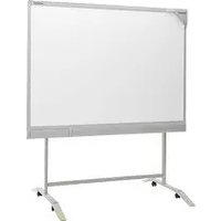


| Product Type | Interactive Electronic Board (elite Panaboard) |
| Model Number | UB-T760 |
| Dimensions (H x W x D) | 1340 mm x 1752 mm x 89 mm (4 ft 4 7/8 in x 5 ft 9 1/8 in x 3 1/2 in) |
| Weight | 26 kg (57.32 lbs) |
| Power Supply | AC 100 V – 240 V, 50 Hz/60 Hz |
| Power Consumption (Operation) | 0.1 A |
| Interface | USB 2.0 |
| Screen Board Size (H x W) | 1175 mm x 1692 mm (3 ft 10 3/8 in x 5 ft 6 3/4 in) |
| Interactive Effective Area (H x W) | 1165 mm x 1502 mm (3 ft 10 in x 4 ft 11 1/4 in) |
| Electronic Pen Power | 1 x AAA alkaline battery (LR03) |
| Electronic Pen Battery Life | Approximately 30 hours (continuous use at 25 °C) |
| Operating Temperature | 15 °C to 30 °C (59 °F to 86 °F) |
| Operating Humidity | 30 % to 80 % |
| Storage Temperature | -20 °C to 40 °C (-4 °F to 104 °F) |
| Included Accessories | Power cord (3 m), USB cable (5 m), Software CD-ROM, Electronic pen with 1 AAA battery, 2 replacement penpoints, Operating Instructions, Warranty |
| Main Functions | Interactive pen input, mouse emulation, drawing/annotation, elite Panaboard book software, calibration, screen shade, remote collaboration |
| Cleaning Instructions | Wipe with a soft, damp cloth. Use white-board cleaner or mild household detergent for stubborn spots. Do not use dry cloth, thinner, benzene, or abrasives. |
| Safety Certifications | FCC Class A, CE compliant, meets EN ISO 7779 for noise |
| Mounting Options | Wall mount (M6 screws, not included) or optional stand KX-B061 (sold separately) |
Frequently Asked Questions - UB-T760 PANASONIC
User questions about UB-T760 PANASONIC
0 question about this device. Answer the ones you know or ask your own.
Ask a new question about this device
Download the instructions for your Tablet in PDF format for free! Find your manual UB-T760 - PANASONIC and take your electronic device back in hand. On this page are published all the documents necessary for the use of your device. UB-T760 by PANASONIC.
USER MANUAL UB-T760 PANASONIC
Operating Instructions
(For Basic Operations)
Electronic Board
(elite Panaboard)
Model No. UB-T780

Stand is sold separately.
Installation Manual Included (for qualified service personnel)
• To assemble this unit, please refer to the Installation Manual on pages 31 through 50. - Before operating this unit, please read these instructions completely and keep them carefully for future reference. - This unit is designed for installation by a qualified servicing dealer. Installation performed by non-authorized individuals could cause safety-related problems with the operation of this equipment.
For U.S.A. only:
• To locate the closest authorized dealer in your area, please call 1-800-449-8989.
Introduction
Thank you for purchasing the Panasonic Electronic Board.
For optimum performance and safety, please read these instructions carefully.
Feature Highlights
By connecting the elite Panaboard to a computer and using a projector to display the contents of the computer's screen on the elite Panaboard, you can do the following.
Electronic Pen Features
- Manipulate objects on the computer screen by using the electronic pen as a mouse.
- Draw and erase lines on the computer screen by using the electronic pen.
- Save images of the computer screen that were created by drawing with the electronic pen.
elite Panaboard book
Use the elite Panaboard book software that supports elite Panaboard operations, such as writing, drawing, attaching images and computer operations. This software lets you save the contents of the screen on your computer and retrieve it for later use.
Usage Scenarios
For Education
- Create an effective learning environment by projecting a variety of educational software onto the elite Panaboard and, with the electronic pen, directly manipulate the software and write and draw on the screen.
- With several tools at your disposal for aiding in explanations, such as illustration and marker tools, you can keep students' attention through a dynamic screen display.
- Draw your students' interest by using the screen shade feature to show questions to students while hiding the answers, and incrementally showing the rest of the screen.
- The teacher can prepare materials before class to display on the elite Panaboard.
For Business
- Visually communicate your product's characteristics and create an appealing presentation of your product by displaying images and using the electronic pen to highlight key points.
- Display the contents, including what you have written using the electronic pen, of the elite Panaboard in your company in real time on a remote computer by using TV conferencing equipment.
Things you should keep a record of
Attach your sales receipt here
| For your future reference | |
| Date of purchase | |
| Serial number | |
| Dealer's name | |
| Dealer's address | |
| Dealer's tel no. | |
About the Operating Instructions
There are 2 separate operating manuals for the elite Panaboard.
| For Basic Operations(this document) | Instructions for connecting and operating the elite Panaboard, as well as instructions for installation construction. |
| For Software(electronic documentation) | Instructions for the included elite Panaboard software and elite Panaboard book. The manual "Operating Instructions (For Software)" is located on the included CD-ROM. You can view the "Operating Instructions (For Software)" after you install the elite Panaboard Software on your computer. For details on viewing the manual, see "Viewing the Electronic Documentation" (page 24). |
Abbreviations
Windows® refers to the Microsoft® Windows® operating system.
Windows® 2000 refers to the Microsoft® Windows® 2000 operating system.
Windows® XP refers to the Microsoft® Windows® XP operating system.
Windows Vista® refers to the Microsoft® Windows Vista® operating system.
DirectX® refers to the Microsoft® DirectX® application programming interface.
Trademarks
• Microsoft, Windows, Windows Vista, DirectX, and Windows Media are either registered trademarks or trademarks of Microsoft Corporation in the United States and/or other countries. - IBM and AT are trademarks of International Business Machines Corporation in the United States, other countries, or both. - Intel and Pentium are trademarks or registered trademarks of Intel Corporation in the United States and other countries. - Adobe, Reader and Flash are either registered trademarks or trademarks of Adobe Systems Incorporated in the United States and/or other countries. - All other trademarks identified herein are the property of their respective owners.
Federal Communications Commission Requirements
For United States Only
Note
This equipment has been tested and found to comply with the limits for a Class A digital device, pursuant to part 15 of the FCC Rules. These limits are designed to provide reasonable protection against harmful interference when the equipment is operated in a commercial environment. This equipment generates, uses, and can radiate radio frequency energy and, if not installed and used in accordance with the instruction manual, may cause harmful interference to radio communications. Operation of this equipment in a residential area is likely to cause harmful interference in which case the user will be required to correct the interference at his own expense.
FCC Warning
To assure continued FCC compliance, the user must use only the provided power supply cord. Also, any unauthorized changes or modifications to this equipment would void the user's authority to operate this device.
Warning about saving data
When the system storage device or any of its optional storage device is adversely affected by operational errors, static electricity, electrical noise, vibration, dust or when the power has been cut off due to malfunction, repair or inadvertently, the memory contents may be lost or changed. Before operating the system, make a point of reading the precautionary notes in the Operating Instructions and the help information, and observe them during operation.
Please observe carefully the following precaution:
- Make absolutely sure that all important data is saved by back-up or the original is saved.
The manufacturer hereby declares that it cannot be held accountable for any loss or change in any data stored on floppy disks, hard disks, optical disks, or other memory devices.
System Requirements
| Computer | IBM® PC/AT® or compatible with a CD-ROM drive |
| CPU | Intel® Pentium® 4 processor or later |
| Operating System | Windows 2000 SP4 / Windows XP / Windows Vista |
| Interface | USB 2.0 |
| Memory (RAM) | 256 MB or greater (Windows 2000 SP4)512 MB or greater (Windows XP)512 MB or greater (Windows Vista) |
| Hard Disk | Hard disk with at least 200 MB of free space (not including the space require for saving files) |
Note
- To run the elite Panaboard software, Microsoft .NET Framework 1.1 or later and DirectX 7.0 or later are required. When you install the elite Panaboard software on the CD-ROM, .NET Framework 1.1 will be installed on your computer if it is not already installed. • The system requirements above do not meet the recommended specifications of all operating systems.
- You must have Windows Media® Player 10 or later, or Adobe® Flash® Player installed to insert and play back video.
- Inserting and playing back video is not supported in Windows 2000 SP4.
- The handwriting recognition feature is supported in Windows Vista Ultimate, Windows Vista Home Premium, Windows Vista Business, and Windows XP Tablet PC Edition 2005.
- If you are using Windows 2000 SP4 or later, or Windows XP Professional, you must have the Tablet PC SDK and Microsoft Windows XP Tablet PC Edition 2005 Recognizer Pack installed to use the handwriting recognition feature.
- The handwriting recognition feature is not supported in Windows Vista Home Basic and Windows XP Home Edition.
- You must have enough available hard disk space in order to record and play back video.
Exemption of Liability
Panasonic Communications Co., Ltd. is not responsible for accidents or injuries caused by, but not limited to, the following:
- Altering the device or improper installation construction.
- Using the device for purposes beyond its intended use.
- Earthquake, fire, flood, tidal wave, hurricane, lightning or other natural phenomena.
- Natural aging of the building or similar phenomena.
For FRG Users (For Germany Only)
Note
Machine noise information regulation - 3.GPSGV, the maximum sound pressure level is 70 dB(A) or less, in conformity with EN ISO 7779.
This equipment is not for use at video display work stations according to BildscharbV.
Table of Contents
For Your Safety 8
For Your Safety 8
For Users 8
Safety Information (For United Kingdom Only) 11
Precautions 12
Usage 13
Included Accessories ....13
Names and Uses of the Parts ....14
Connecting External Components ....17
Installing the elite Panaboard software ....19
Setting the Projector ....20
Setting Your System (Calibration) 21
Starting the elite Panaboard software and Performing Calibration ....22
Uninstalling the elite Panaboard software 23
Viewing the Electronic Documentation 24
Download the Latest Software ....24
Appendix 25
Daily Care 25
Cleaning the elite Panaboard 25
Replacing the Battery in the Electronic Pen 25
Replacing the Penpoint of the Electronic Pen 26
Troubleshooting 27
Specifications 29
Optional Devices and Accessories 30
Installation Manual 31
Installation Manual (for qualified service personnel) ....31
For Your Safety 31
Notice 31
Included Accessories 33
Wall Mounting Construction 35
Checking the Wall 35
Installing the Wall Mounting Plates 36
Wall Types and Installation Procedures 37
Stand Assembly (Sold Separately) 39
Included Parts 39
Assembly Instructions 40
Assembly Instructions ....43
Preparing for Removing the elite Panaboard from Its Packaging 43
Assembling the elite Panaboard 44
Confirming the elite Panaboard Operation ....49
Confirming the Interactive Features 49
Repackaging 50
For Your Safety
To prevent severe injury and loss of life, read this section carefully before using the unit to ensure proper and safe operation of your unit.
The following graphic symbols are used in this Operating Instructions manual.
 | WARNING | Denotes a potential hazard that could result in serious injury or death. | |
 | CAUTION | Denotes hazards that could result in minor injury or damage to the unit. | |
 |  |  | These symbols are used to alert operators to a specific operating procedure that must not be performed. |
 | |||
 |  |  | These symbols are used to alert operators to a specific operating procedure that must be emphasized in order to operate the unit safely. |
WARNING
CAUTION
For Users
WARNING
Power and Ground Connection

The power source voltage of this unit is listed on the nameplate. Only plug the unit into an AC outlet with the proper voltage. If you use a cord with an unspecified current rating, the unit or plug may emit smoke or become hot to the touch.

When you operate this product, the power outlet should be near the product and easily accessible.

To ensure safe operation, the power cord supplied must be inserted into a standard three-prong AC outlet that is effectively grounded (earthed) through the normal wiring.

The fact that the equipment operates satisfactorily does not imply that the power point is grounded (earthed) and that the installation is completely safe. For your safety, if in any doubt about the effective grounding (earthing) of the power point, consult a qualified electrician.

If the plug cannot be inserted into the AC outlet, contact a licensed electrician to replace the AC outlet with a properly grounded (earthed) one.

Do not defeat the purpose of the grounding (earthing) plug (e.g., do not use a conversion plug).

Plug the power cord firmly into an AC outlet. Otherwise, it can cause fire or electric shock.

Do not pull, bend, rest objects on, or chafe the power cord and plug. Damage to the power cord or plug can cause fire or electric shock.

Do not attempt to repair the power cord or plug. If the power cord or plug is damaged or frayed, contact an authorized service representative for a replacement.

Ensure that the plug connection is free of dust. In a damp environment, a contaminated connector can draw a significant amount of current that can generate heat and eventually cause fire if left unattended over an extended period of time.

Never touch the plug with wet hands. Danger of electric shock exists.

Stop operation immediately if your unit emits smoke, excessive heat, abnormal smell, or unusual noise. These conditions can cause fire or electric shock. Immediately turn the unit off and unplug the power cord, and contact your dealer for service.

When disconnecting the unit, grasp the plug instead of the cord. Pulling on a cord forcibly can damage it and cause fire or electric shock.

During thunderstorms, do not touch the unit and plug. It may cause an electric shock.
Installation and Relocation

Have the unit installed, removed and disposed of only by qualified service personnel.

When the unit will no longer be used, in order to prevent it from falling, do not leave the unit installed, but remove it. If the unit falls, it can cause injury.
Operating Safeguards

If metal fragments or water gets into the unit, turn the unit off and unplug the unit immediately. Contact your dealer for service. Operating the contaminated unit can cause fire or electric shock.

Never open or remove unit covers that are screwed with screws unless specifically instructed in the "Operating Instructions". A high-voltage component can cause electric shock.

Do not alter the unit or modify any parts. Alteration or modification can cause fire or electric shock.

CHOKING HAZARD Keep the penpoint and battery out of reach of children to prevent swallowing.
Battery

Use only the specified type of battery. Using the incorrect type of battery can result in overheating/burning or leakage of battery acid.

Make sure that the battery is installed with the correct polarity as indicated on the battery holder. Incorrectly installed batteries may burst or leak, resulting in injuries.

Batteries that seem worn down or damaged should not be used. Using worn down or damaged batteries may result in leaking.

Do not charge, short, heat, break or throw in a fire, as it may result in the battery leaking, generating heat, or bursting.

When disposing of the battery, cover the battery contacts with insulation (e.g., tape). Direct contact with other batteries may result in leaking, fire, or explosion.

Do not solder the battery, as it may result in the battery leaking, generating heat, or bursting.

CAUTION
Power

When the unit is not used over an extended period of time, switch it off and unplug it. If an unused unit is left connected to a power source for a long period, degraded insulation may cause electric shock, current leakage, or fire.

The unit should be used only with the power cord enclosed with the unit.
Installation and Relocation

Do not position the unit in a location where it is unstable.

Do not place the unit in a hot, humid, or dusty environment. Prolonged exposure to these adverse conditions may cause fire or electric shock.

To prevent fire or shock hazard, do not expose this unit to rain or any type of moisture.
When moving the unit, be sure to unplug the power cord from the AC outlet. If the unit is moved with the power cord attached, it can cause damage to the cord which could result in fire or electric shock.

After installing or moving the unit, lock the casters and set the fall-prevention extension legs.
Locking the casters (Push this side) Push to lock


Move this unit with two persons. Otherwise, this unit may fall down and cause injury.
Operating Safeguards

If the unit is fallen down or damaged, turn the unit off and unplug the power cord. Otherwise, it may cause fire or electric shock.

Do not lean against the screen or on the cover (lower), even if the unit is mounted on the wall.
Battery

When the unit is not used over an extended period of time, take the batteries out of the unit. Otherwise, the batteries may leak. Do not use the leaked batteries.
Safety Information (For United Kingdom Only)
This appliance is supplied with a moulded three pin mains plug for your safety and convenience.
A 5 amp. fuse is fitted in this plug. Should the fuse need to be replaced please ensure that the replacement fuse has a rating of 5 amps. and that it is approved by ASTA or BSI to BS1362. Check for the ASTA mark for the BSI mark 📋 on the body of the fuse. If the plug contains a removable fuse cover you must ensure that it is refitted when the fuse is replaced. If you lose the fuse cover the plug must not be used until a replacement cover is obtained. A replacement fuse cover can be purchased from your local Panasonic Dealer.
If the fitted moulded plug is unsuitable for the socket outlet in your home then the fuse should be removed and the plug cut off and disposed of safely.
There is a danger of severe electrical shock if the cut off plug is inserted into any 13 amp. socket.
If a new plug is to be fitted please observe the wiring code as shown below. If in any doubt please consult a qualified electrician.
WARNING: This appliance must be earthed.
IMPORTANT: The wires in this mains lead are coloured in accordance with the following code.
Green-and Yellow: Earth
Blue: Neutral
Brown: Live
As the colours of the wire in the mains lead of this appliance may not correspond with the coloured markings identifying the terminals in your plug, proceed as follows.
The wire which is coloured Green-and-Yellow must be connected to the terminal in the plug which is marked with the letter E or by the Earth symbol or coloured Green or Green-and-Yellow.
The wire which is coloured Blue must be connected to the terminal in the plug which is marked with the letter N or coloured Black.
The wire which is coloured Brown must be connected to the terminal in the plug which is marked with the letter L or coloured Red.
How to replace the fuse:

Open the fuse compartment with a screwdriver and replace the fuse.
Precautions
About Using the Battery
If a battery is used improperly, the battery may leak, causing corrosion of the unit, or it may burst. To prevent this, always follow the precaution given below.
- If the electronic pen ceases to function because the battery has run out, remove it immediately and dispose of it according to local regulations. Leaving a drained battery in the electronic pen may result in leakage.
About Disposing of the Battery
For Brazil

Included Accessories
Check that all of the following items are included with your elite Panaboard. In the event that an item is missing, please contact your dealer.
List of Accessories
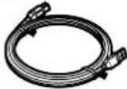
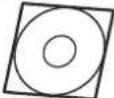
| Power Cord(3 m [9 ft. 10 3/8 in.]) | 1 | USB Cable(5 m [16 ft. 5 3/8 in.]) | 1 | Software CD-ROM 1 | |
 |  |  | |||
| AAA Battery (LR03)(Disposable) | 1 | Electronic Pen 1 | Penpoint(Replacement) | 2 | |
 |  |  | |||
| Operating Instructions(For Basic Operations)(this document) | 1 | Warranty 1 | |||
 |  | ||||
Note
- The illustration of the power cord shown above is for the United States. The shape of the plug may vary depending on country/area.
- Stand is sold separately.
- Store the extra penpoint along with this operating manual.
- The warranty may not be included depending on country/area.
About Using the CD-ROM
To prevent damage to the CD-ROM:
- Do not touch or write on the surface of the disc.
- Do not leave the disc out of the protective case.
- Do not leave the disc in the direct sunlight or near heat sources.
- Do not place heavy objects on the disc case or drop the case.
• To clean the disc, hold the disc by its edges and wipe it from the center to the edges with a dry, soft cloth.
Names and Uses of the Parts
Screen
Front View
Rear View
Notice
- The elite Panaboard is designed exclusively for projector images. Do not write on the screen board with a white-board marker. If you write on the screen board with a white-board marker, you cannot erase it with a standard eraser. Use a commercially available melamine foam eraser to erase.
Electronic Pen

Penpoint
When you push down on the penpoint, ultrasonic waves and infrared signals are transmitted, and equivalent of a left mouse click is performed.
Ultrasonic Emitter
Do not block this area with your fingers.
Doing so will prevent the elite Panaboard from correctly detecting the electronic pen's position.
Infrared Emitter
Do not block this area with your fingers.
Doing so will prevent the elite Panaboard from correctly detecting the electronic pen's position.
Pen Button
Performs the same function as a right-click with a mouse.
Battery Cover
Notice
- Use the electronic pen by holding it at a right angle to the screen board. Holding it at an angle can cause its position to be read incorrectly.

- Do not use multiple pens at the same time. This can result in erroneous operation.
- Do not push the penpoint while holding the pen close to the elite Panaboard. Doing so can cause erroneous behavior.
Note
- The electronic pen switches to power-save mode after about 30 minutes.
- When waking up the pen from power-save mode by pushing the penpoint, the pen's reaction may be slow.
- When operating the electronic pen, you will hear a buzzing sound due to the pen emitting ultrasonic waves for location detection. This sound does not have any negative effects for nearby people or devices. It will not cause electrical shocks.
Inserting (Replacing) Batteries
1. Remove (replace) the battery cover.
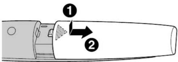
- When replacing the cover, follow the procedure in reverse.
2. Insert (exchange) the battery and replace the cover.

• Make sure to use a AAA alkaline battery, and ensure that ① and face the correct directions.
Connecting External Components
- Set the power switch to "O" (OFF), connect the power cord (included) to the elite Panaboard, and plug the power cord into an AC outlet.

- Plug the power cord into an outlet that is close to the elite Panaboard and in a location that is easy to unplug.
- If you are using the optional stand, plug the power cord into the AC inlet, and secure the cord as shown in the illustrations below.
When attaching the power cord downward.
When attaching the power cord along the lower side of the elite Panaboard.


- About Grounding: If you cannot connect the grounding line, contact your dealer. The cost of installing a grounding connection is not included in the price of the elite Panaboard.
- The included power cord is exclusively for use with the elite Panaboard. Do not use it with any other devices.
- Connect the elite Panaboard to a computer using the USB cable (included).
- elite Panaboard: Plug the B connector (smaller connector) into the elite Panaboard's USB port. Computer: Plug the A connector (larger connector) into a USB port on the computer.
- Do not connect the elite Panaboard via a USB hub. This could result in erroneous operation.

- Connect the computer to a projector.
• For instructions on connecting your computer and projector, refer to the respective instruction manuals.
About the Usage Location
- Do not place the elite Panaboard where it is directly exposed to sunlight, near a stove, near a heating/cooling vent, or exposed to strong winds.
- Do not use the elite Panaboard in a location less than 10 °C (50 °F) or in a location subject to extreme changes in temperature.
Note
- If you use the elite Panaboard under the conditions above, there is a risk that the elite Panaboard will not operate correctly.
Moving the elite Panaboard When Using the Stand (Sold Separately)
- Make sure that the power switch is set to "O" (OFF), and disconnect the power cord and USB cable.
- Release the locks on the casters.
- Move the elite Panaboard, avoid banging or shaking the board.
Notice
• Always move the elite Panaboard with 2 people. - Do not drag or step on the cable.
- Lock the casters.
Installing the elite Panaboard software
You need to install the elite Panaboard software on the computer that will be used with the elite Panaboard. To install the elite Panaboard software, follow the procedure below.
Notice
- Do not connect the USB cable until the installation is completed.
- Do not connect more than 1 elite Panaboard to the same computer. (Doing so can cause erroneous behavior on the computer.)
- Turn on your computer and start the Windows operating system.
- Log into an account with Administrator privileges.
- Insert the included CD-ROM into the CD-ROM drive.
• The setup screen will be displayed. - If the setup screen does not appear, select your CD-ROM drive in Explorer and double-click "Menu.exe". - In Windows Vista, if the Autoplay dialog box is displayed, click [Run Menu.exe].
- When the "Welcome" screen has been displayed, click [Next].
- Click [Install elite Panaboard].

- If you agree to the terms in the "License Agreement", click [Yes].
- In Windows Vista, if the "User Account Control" window is displayed, click [Continue] to continue with the installation.
- When the following screen is displayed, confirm that the USB cable is not connected to your computer or the elite Panaboard, and click [OK].
- If the USB cable is connected to the elite Panaboard, disconnect the cable, and click [OK].
- If .NET Framework 1.1 or later is not installed, an installation screen will be displayed. Follow the on-screen directions to install these components.
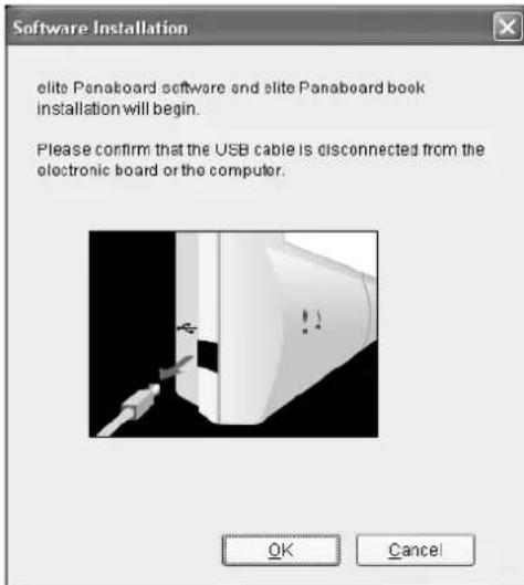
- When the installation wizard is displayed, follow the on-screen instructions and continue with the installation.
- When installation has finished, click [Finish].
- Restart your computer if you are prompted to do so.
- The group [elite Panaboard] will be created in the [Panasonic] group in the program menu.
• The following items will appear in the [elite Panaboard] group:
- elite Panaboard software
- elite Panaboard book
- Operating Instructions for Basic Operations
- Operating Instructions for Software – Download the latest version
Setting the Projector
Set up your projector as instructed below.
About Positioning the Image
- When projecting an image, make sure that the edge of the projected image is at least 5 mm (1/4 in.) from the screen frame. The electronic pen may not function correctly within 50 mm (2 in.) of the position sensor in the upper-left corner of the screen board.

Project the Image as a Rectangle
- Adjust the location of the projector to project at a right angle with the elite Panaboard.
![graph TD A["Computer with monitor icon"] --> B["Device with X"] C["Computer with monitor icon"] --> D["Device with X"] E["Computer with monitor icon"] --> F["Device with X"] G["Computer with monitor icon"] --> H["Device with X"] I["Computer with monitor icon"] --> J["Device with X"] K["Computer with…](/content/2026/05/845956/images/431e4a96b2310bb98f0b6dcba81372e349a49bc2f659b2f352430557ed43b358.jpg)
- If the image is projected trapezoidally, the position of the electronic pen may not be read correctly. Adjust the projector so that the projected image is a rectangle. Refer to your projector's documentation for information on adjusting the projected image.

Set the Proper Resolution
- Set your computer's and projector's resolutions to the most appropriate setting. If the resolution is not set properly, the image will be difficult to see. Particularly, if the projector's resolution is lower than the computer's, thin lines can appear cut or broken. Refer to your projector's documentation for information on adjusting the resolution.
Do Not Look Directly into the Projector Lamp
- When using a projector, try to avoid looking directly into the projector lamp. Doing so can hurt your eyes.
Setting Your System (Calibration)
About Calibration
Calibration is setting up the elite Panaboard and projector so that lines and comments drawn on the screen board with the electronic pen will be correctly displayed on the image projected onto the screen board. Be sure to perform calibration before use. After you have set up the elite Panaboard, project an image onto the screen board and use the elite Panaboard software installed on your computer to perform calibration.
After Calibration
Do Not Move the elite Panaboard or the Projector
- The position of the projected image and the electronic pen will become misaligned in the following cases, requiring you to re-calibrate their positions. – The location of the projector changed. – The location of the elite Panaboard changed.
- The image area or placement was changed due to changes in the zoom, focus, etc.
- The resolution of the projector or the computer changed.
- If you are using the elite Panaboard installed on a stand, be aware that accidentally hitting the elite Panaboard or pushing too strongly with the electronic pen while operating can move the stand's position, which will result in misalignment of the projected image and the electronic pen's position.
- Make sure to lock the stand's casters when using the elite Panaboard, as failing to do so can cause misalignment.
Starting the elite Panaboard software and Performing Calibration
- Turn on the elite Panaboard.
- Connect the elite Panaboard to your computer with the USB cable.
- The elite Panaboard software starts automatically.
- When you start the elite Panaboard software for the first time, the calibration screen is displayed.
- Restart your computer if you are prompted to do so. After the computer has restarted, connect the elite Panaboard to your computer with the USB cable.
- Perform calibration.
- Press the electronic pen at a right angle against the board at the intersecting points of each circle until it disappears (about 2 seconds). Repeat in the order shown in the illustration below.


- Hold and press the electronic pen at a right angle to the screen board.
- When you push down on the penpoint, the electronic pen makes a buzzing sound.
- When the position of the indicated point has been determined correctly, calibration automatically moves to the next point.
- When calibration has finished normally, a completion dialog box is displayed.

- Click [OK].
- If the elite Panaboard and projector are fixed so that they will not move (Wall mounted case), select the [Always use this calibration information.] check box, and click [OK] to skip calibration from the next time you start the elite Panaboard software.
• After calibration has completed, the icon is displayed in the notification area, and the Desktop Drawing Tool is automatically displayed.

[Desktop Drawing Tool]
- You will be able to use elite Panaboard software.
Note
- For detailed information about using the elite Panaboard software, refer to the included electronic manual or the help menu. For instructions on viewing the electronic documentation "Operating Instructions (For Software)", see "Viewing the Electronic Documentation" (page 24).
Exiting the elite Panaboard software
Right-click on the 📄 icon in the notification area, and select [Exit] from the menu.
Uninstalling the elite Panaboard software
If it is necessary to uninstall the elite Panaboard software, follow the procedure below.
- Turn on your computer and start Windows.
- Log into an account with Administrator privileges.
- Select [Add or Remove Programs] from the Control Panel.
- In Windows 2000, select [Add/Remove Programs], and in Windows Vista, select [Uninstall a program].
- Select Panasonic elite Panaboard, then remove it.
- Follow the on-screen instructions.
- When uninstallation is complete, restart your computer.
Viewing the Electronic Documentation
Follow the procedure below to view the electronic documentation "Operating Instructions (For Software)".
- Turn on your computer and start Windows.
- Open "Operating Instructions (For Software)" from the Start menu.
([Start] → [All Programs] → [Panasonic] → [elite Panaboard] → [Operating Instructions for Software])
- The electronic documentation will be displayed.
- For Windows 2000, [Programs] is displayed instead of [All Programs].
Note
- To view the electronic documentation, you must have Adobe® Reader® installed on your computer. If your computer is connected to the Internet, you can download Adobe Reader from Adobe's web site.
Download the Latest Software
Follow the procedure below to download the latest version of the software from the download web site.
- Turn on your computer and start Windows.
- On the Start menu, point to [All Programs] → [Panasonic] → [elite Panaboard], and click [Download the latest version].
Daily Care
When cleaning the elite Panaboard or inside the elite Panaboard, make sure to switch off the power and unplug the power cord from the AC outlet.
Cleaning the elite Panaboard
Gently wipe the elite Panaboard with a soft, moist cloth.
Notice
- For spots that are difficult to remove, use commercially available white-board cleaner or neutral household cleaner diluted with water.
- The elite Panaboard is designed exclusively for projector images. If you write on the screen board with a white-board marker, you cannot erase it with a standard eraser. Use a commercially available melamine foam eraser to erase.
- Do not wipe the screen board with a dry cloth. (Doing so can cause static electricity build-up.)
- Do not use thinner, benzene, or abrasive chemicals to clean. (Doing so can result in discoloration.)
Replacing the Battery in the Electronic Pen
When the charge in the battery in the electronic pen is low, the message, "The pen battery is low. Replace the battery soon." will be displayed on the computer screen. Continued use of the electronic pen can lead to poor performance. Replace the battery as soon as possible. See "Inserting (Replacing) Batteries" (page 16) for details on replacing the battery.
- Promptly remove used batteries and properly dispose of them following your local laws and regulations.
For Brazil
Replacing the Penpoint of the Electronic Pen
As the penpoint of the electronic pen becomes worn, a hole will appear in the penpoint. Continuing to use the electronic pen in this condition can cause damage to the screen or unsatisfactory operation, so replace the penpoint with a new one as soon as possible.

Troubleshooting
When experiencing problems, please refer to the table below for possible solutions. If the problem persists, contact your dealer.
| Symptom Possible cause and solution See page | ||
| The LEDs do not light when the power switch is turned on. | Check that the power cord is properly plugged in.→ If the problem persists, turn off the power, and then turn it on again. | - |
| Red LED is blinking. | Turn off the power, and turn it on again.→ If the problem persists, contact your dealer. | - |
| The computer does not recognize the elite Panaboard. | · The USB cable is connected to a USB hub.→ Do not connect the elite Panaboard through a USB hub.· Check that the elite Panaboard is in an operable state, and that the USB cable is properly connected. | - |
| The connection between the computer and the elite Panaboard is unexpectedly lost. | Check that the elite Panaboard is in an operable state, and that the USB cable is properly connected. | - |
| The electronic pen's position is not correct. | The projected image is misaligned.→ Perform the calibration again. | 22 |
| Drawn lines and comments are not completely displayed or are displayed in the wrong location.The electronic pen loses the functions. | · You are holding the electronic pen at an angle.· You are operating the elite Panaboard in direct sunlight or other strong lighting.· Infrared controllers (e.g., a television remote control) are being used and pointed towards the position sensor.· There is a wall or ceiling close to the sides of the elite Panaboard.· There is an air-conditioner vent close to the elite Panaboard.· A plasma or LCD television is being used near by the elite Panaboard.· Part of the position sensor is blocked.· You are covering part of the electronic pen's sensor with your hand.· Several electronic pens are being used at the same time.· The electronic pen is low on batteries.→ Check that none of the above is causing the problem.If misalignment is not caused by any of the above, perform the calibration again. | - |
| Extra lines are displayed on the computer screen. | Apart from writing directly on the elite Panaboard with the electronic pen, you pushed the penpoint with your finger while holding it close to the elite Panaboard.→ Avoid pushing the penpoint with your finger. | - |
| Symptom Possible | cause and solution See page | |
| The message "The pen battery is low. Replace the battery soon." is displayed on the computer screen. | Replace the electronic pen's battery with a new one. | 1625 |
| Marks written with a white-board marker cannot be erased. | Because the elite Panaboard is designed exclusively for projector images, you cannot erase the marks with a standard eraser.→ Use a commercially available melamine foam eraser to erase. | 25 |
Specifications
| Model Number UB-T780 | ||
| General Power | AC 100 V–240 V, 50 Hz/60 Hz | |
| Power Consumption: During Operation | 0.1 A | |
| External Dimensions: Height × Width × Depth | 1,340 mm × 1,752 mm × 89 mm(4 ft. 47/8 in. × 5 ft. 91/8 in. × 31/2 in.) | |
| Weight 26 kg (57.32 lbs) | ||
| Operating Environment Temperature | 15 °C to 30 °C (59 °F to 86 °F)Humidity: 30 % to 80 % | |
| Storage Environment Temperature | -20 °C to 40 °C (-4 °F to 104 °F)Humidity: 15 % to 80 % | |
| Interface USB 2.0 | ||
| Input Unit Screen Board Size: Height × Width | 1,175 mm × 1,692 mm(3 ft. 103/8 in. × 5 ft. 63/4 in.) | |
| Interactive Features | Effective Area: Height × Width | 1,165 mm × 1,502 mm (3 ft. 10 in. × 4 ft. 111/4 in.)Project the image so that it is at least 5 mm ( 1/4 in.) from the screen frame. The electronic pen may not function correctly within 50 mm (2 in.) of the position sensor in the upper-left corner of the screen board. |
| Electronic Pen Power LR03 (AA | A alkaline dry cell battery) × 1 | |
| Electronic Pen Battery Life 30 hours | (when used continuously at 25 °C [77 °F])* When using Panasonic LR03 alkaline dry-cell batteries. | |
Optional Devices and Accessories
| Optional Device Stand KX-B061 | ||
| Accessories Electronic Pen UE-608025 |
- To purchase separately sold items, contact your dealer.
Installation Manual (for qualified service personnel)
- Request assembly of the Electronic Board, stand, and wall mounting from your dealer.
- Before assembly and construction, read this section thoroughly.
- When installing the elite Panaboard on a wall or on the stand, perform installation with 2 people.
For Your Safety
To prevent severe injury and loss of life, read this section carefully before using the unit to ensure proper and safe operation of your unit.
The following graphic symbols are used in this Installation Manual.

WARNING
Denotes a potential hazard that could result in serious injury or death.

CAUTION
Denotes hazards that could result in minor injury or damage to the unit.


These symbols are used to alert operators to a specific operating procedure that must not be performed.


These symbols are used to alert operators to a specific operating procedure that must be emphasized in order to operate the unit safely.
Notice
WARNING

Safety check must be done by qualified service personnel after installing this option.

Be sure to disconnect the power cord while installing the unit. Otherwise, it may cause electric shock or injury.

Be sure to use the specified parts for the installation. Otherwise, it may cause fire, electric shock or injury.

Notes in the operating instructions or notes of labels on the cabinet, chassis or parts should be observed.

Do not alter the unit and install. Installing an altered unit can cause fire, electric shock or injury.

Have the unit installed, removed and disposed of only by qualified service personnel.

CAUTION

After installing or moving the electronic board, lock the casters and set the fall-prevention extension legs.
Locking the casters (Push this side) Push to lock


If the unit is hung on a wall, confirm the wall must be capable of supporting at least the following weight.
1,324 N (135 kgf)

Do not attach the electronic board to mortared walls. Accidental electric leakage from the wall mounting plate bolts to metal laths or wire laths can cause heat, smoke or a fire.

Confirm the bolts of the unit are certainly caught by the wall mounting plate by pulling the unit after hanging the unit on the wall mounting plate if the unit is mounted on a wall.

Be sure to put on a glove to avoid electric shock or injury.
Included Accessories
Confirm that the following items are included with the elite Panaboard.
| No. | Part Name Illustration Q'ty Remarks | |||
| 1 | Power Cord(3 m [9 ft. 10 3/8 in.]) |  | 1 | The illustration of the power cord is for the United States. The shape of the plug may vary depending on country/area. |
| 2 | USB Cable(5 m [16 ft. 5 3/8 in.]) |  | 1 For computer connection | |
| 3 | CD-ROM 1 |  | Operating Instructions (For Software) Drivers Application software | |
| 4 | Cable Holder 1 For power cord |  | ||
| 5 | Wall Mounting Plate (Left) 1 — | 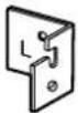 | ||
| 6 | Wall Mounting Plate (Right) 1 — |  | ||
| 7 | Battery (LR03 AAA alkaline battery) |  | 1 For electronic pen | |
| 8 | Electronic Pen 1 — |  | ||
| 9 | Penpoint (Replacement) |  | 2 For electronic pen | |
| 10 | Cable Tie 1 | Fastener for power cord when mounted on a wall | ||
| 11 | Operating Instructions 1 |  | Operating Instructions (For Basic Operations) (includes Installation Manual) | |
| 12 | Warranty 1 |  | May not be included depending on country/area. | |
Notice
- Screws (8 count) for wall mounting are not included. Please purchase screws with a size of M6, appropriate for your type of wall (page 37).
Wall Mounting Construction
Checking the Wall
When mounting on a wall, consult with your building's owner, caretaker or construction manager to determine if the wall strength is sufficient to install the elite Panaboard. For safety, install the elite Panaboard only after thoroughly understanding the type of walls, the appropriate types of screws and the construction method (Page 37).
CAUTION
Do not attach the electronic board to mortared walls. Accidental electric leakage from the wall mounting plate bolts to metal laths or wire laths can cause heat, smoke or fire.
I. Necessary Tools and Parts (not included with the elite Panaboard)
Drill, Screwdriver, Measuring tape, Level
8 screws (M6 size)
II. Before Starting
- Make sure that the wall is strong enough to support the elite Panaboard.
Rated strength: greater than 1,324 N (135 kgf)
Notice
If necessary, reinforce the wall so that it is strong enough to support the elite Panaboard.
- Make sure that the location is large enough to accommodate the elite Panaboard.
Height: greater than 2,000 mm (6 ft. 7 in.)
Width: greater than 1,850 mm (6 ft. 1 in.)
- Make sure that the AC outlet is within 3 m (9 ft. 10 3/8 in.) of where the elite Panaboard will be mounted and that it will not be behind the elite Panaboard.
Installing the Wall Mounting Plates
- Ensure that the wall is strong enough to support the elite Panaboard. Rated strength: greater than 1,324 N (135 kgf)
- Using the measuring tape and level, mark the 8 locations to insert the screws.

Note
- The dotted line in the illustration represents the outer edge of the elite Panaboard.
- Drill 8 holes for the wall mounting plates.
- Drill holes that are appropriate for the screws you are using.
- Install the wall mounting plates using the 4 screws.
- 2 screws are used for each wall mounting plate. The remaining 4 screws are used after installing the elite Panaboard on the wall.

- Screws (8 count) are not included with the elite Panaboard. Please purchase screws with a size of M6, appropriate for your type of wall.
- Tighten the bolt so that it will not become loose.
- When drilling the holes and installing the wall mounting plates, follow the procedure in "Wall Types and Installation Procedures" (page 37).
5. Mount the elite Panaboard on the wall.
See "Assembling the elite Panaboard" (For Wall Mounting → page 44).
Wall Types and Installation Procedures
The method for attaching the wall mounting plates to the wall will vary depending on the wall's structure.
Three available options are listed below.
Other methods may be necessary depending on the wall.
Metal or Concrete walls
Stud plugs (not included) are needed.
![graph TD A["Drill bit"] --> B["Metal or concrete wall"] B --> C["Stud plug"] C --> D["Insert a stud plug in the hole."] D --> E["Wall mounting plate"] E --> F["Bolt"]](/content/2026/05/845956/images/a96df47f550e5aa5f7b8a5438149ae43d2968c5407e78b3ab6a5ce52b65ef488.jpg)
Drill eight holes in the wall.
For the correct hole size, refer to the instructions for the particular stud plugs used.
Insert the bolt through the hole in the wall mounting plate and tighten until the wall mounting plate is securely fixed to the wall.
Plasterboard walls
Split-wing toggles (not included) are needed.
![graph TD A["Plasterboard"] --> B["Split-wing toggle"] B --> C["Wall mounting plate"] C --> D["Bolt"] E["Arms"] --> F["Arms"] F --> G["Final assembled part with arrow indicating motion"]](/content/2026/05/845956/images/532cac9768af2ab536f7252f5115cf796876dc5f53b79b9a71a1821d1663d780.jpg)
Insert the bolt through the hole in the wall mounting plate and into the hole in the wall so that the arms of the split-wing toggle are horizontal.
For the correct hole size, refer to the instructions for the particular split-wing toggles used.
After the arms expand, pull the wall mounting plate out until the arms of the split-wing toggle grip firmly into the wall.
Tighten the bolt until the wall mounting plate is securely fixed into the wall.
Wooden walls
Wood screws (not included) are needed.

Insert the wood screw through the hole in the wall mounting plate and tighten until the wall mounting plate is securely fixed to the wall.
For the correct hole size, refer to the instructions for the particular wood screws used.
Stand Assembly (Sold Separately)
Included Parts
Check that the following parts are included with the stand (KX-BP061).
| No. Part Name Illustration Q'ty | |||
| 1 | Stand Base 2 |  | |
| 2 | Support Beam 2 |  | |
| 3 | Cross Bar (A) 2 |  | |
| 4 | Cross Bar (B) 1 |  | |
| 5 | Screw (M6 × 45 mm [ 13/4 in.]) |  | 10 |
| 6 | Two-wing Bolt (M5 × 12 mm [ 1/2 in.]) |  | 2 |
| 7 | Support Bracket 2 |  | |
| 8 | Fall-prevention Extension Leg 4 | 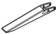 | |
| 9 | Screw (M6 × 60 mm [ 23/8 in.]) |  | 4 |
| 10 | Nut 4 | [SCGA] | |
| 11 | Wrench*1 |  | 1 |
| 12 | Washer 10 |  | |
CAUTION
Before assembly, be sure to lock the casters.

Assembly Instructions
- Assemble the fall-prevention extension legs.

2. Assemble the stand.

Notice
- Do not over-tighten the screw ( ). (Doing so can warp the support beams.)
- Assemble the stand so that the locking casters are on the rear side.
- Pull the fall-prevention extension legs down.

Note
- When folding back the fall-prevention extension legs, release the lock as follows ( ①, ②).

- Mount the elite Panaboard.
See "Assembling the elite Panaboard" (For Mounting on a Stand (Sold Separately) → page 47).
Assembly Instructions
Preparing for Removing the elite Panaboard from Its Packaging
Open the box, remove the accessory box and packing foam, and open the plastic sheet of the elite Panaboard.
![Shipping Box [Accessory Box Contents] Power Cord · 1 USB Cable · 1 CD-ROM · 1 Cable Holder · 1 Wall Mounting Plate (Right, Left) · 1 (Each) Battery · 1 Electronic Pen · 1 Penpoint · 2 Cable Tie · 1 Operating Instructions · 1 Warranty · 1 Electronic Board Shipping Box](/content/2026/05/845956/images/39e28ab9e75826396cf9f434aaae9de248848bdce57bf51fb6f1a84a89d4c022.jpg)
Notice
- When handling the screen board, hold it by the edge frame and not the screen board itself. (Holding the screen board can result in damage.) The packing materials in the shipping box are necessary for repackaging, so keep them in a safe place.
Note
The warranty may not be included depending on country/area.
Assembling the elite Panaboard For Wall Mounting
- Loosely wrap the power cord with the cable tie, and plug the power cord into the AC inlet.
Connect the power cord to the elite Panaboard before installing on a wall.

- Insert the end of the cable tie into the cable tie fastening hole on the lower frame cover.

- Pull the loose end of the cable tie to tighten it, and install the power cord depending on the location of the outlet, as illustrated in the following diagrams.
When attaching the power cord downward.

When attaching the power cord along the lower side of the elite Panaboard.

Fasten the power cord with the cable tie.
- Hang the elite Panaboard on the wall mounting plates with the screw heads.

- Remove the lower frame cover.
Remove the left and right screws, and then remove the lower frame cover from the main unit of the elite Panaboard.

- Remove the 4 latches from the board attachment by pushing them towards the rear.

- Fasten to the wall.
Using the remaining 4 screws, securely fasten the lower portion of the board attachment to the wall.

- Reattach the lower frame cover.
Attach the lower frame cover to the lower side of the elite Panaboard, and tighten both left and right screws so that the cover does not protrude.
How to Attach the Lower Frame Cover
a. Holding the lower frame cover with both hands, slide it into the guides on both sides.

b. Push the lower frame cover backward ( ①).
While keeping the lower frame cover's rib against the rear side of the guides, push the lower frame cover upwards (2).
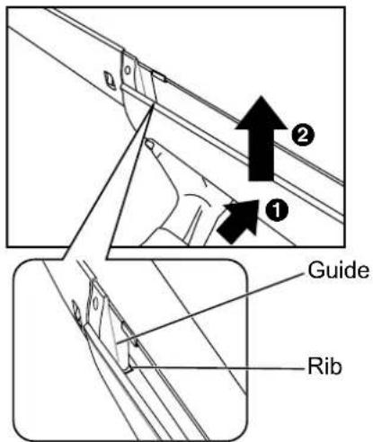
c. Pull the lower frame cover ( ①).
While keeping the rear section of the lower frame cover against the rear of the board, push the lower frame cover up into the rear of the board (2).

d. Push the lower frame cover backward ( ①).
Push the entire lower frame cover up until both ends lock into place (2). Fasten the 2 screws on the bottom side.

Notice
- Be careful not to cut yourself on the board attachments when attaching the lower frame cover.
- When mounting on a wall, do not hit or jolt the elite Panaboard. After mounting, gently apply some weight on the elite Panaboard to make sure that it is securely fastened to the wall.
Note
After installation is complete, use the included cable holder to manage the power cord and USB cable.
9. Wipe the screen board surface.
Gently wipe the screen board surface with a soft, moist cloth.

Notice
- Do not use thinner, benzene, or abrasive chemicals to clean. (Doing so can result in discoloration.)
- Do not wipe the screen board with a dry cloth. (Doing so can cause static electricity build-up.)
- Confirm that the elite Panaboard can operate. See "Confirming the elite Panaboard Operation" (page 49).
For Mounting on a Stand (Sold Separately)
1. Attach the power cord.
- Connect the power cord to the elite Panaboard before installing on the stand.

2. Depending on the location of the outlet, install the power cord as illustrated in the following diagrams.
- When attaching the power cord downward.

- When attaching the power cord along the lower side of the elite Panaboard.

- Hang the elite Panaboard on the stand with the screw heads.

- Secure the elite Panaboard to the stand frame using the two-wing bolts (M5 × 12 mm [1/2 in.] [2 count]) included with the stand.

Note
• After installation is complete, use the included cable holder to manage the power cord and USB cable.
- When installing the elite Panaboard on the stand, you can adjust its height to 4 different levels. When changing the height, remove the left and right screws from the back of the elite Panaboard, and securely insert them at the desired height. Torque (greater than 1 N·m [10 kgf·cm (9 lbf·in.)]).
| elite Panaboard Height | Screw Position |
| -100 mm (-4 in.) Highest | |
| Standard 2nd from top | |
| +100 mm (+4 in.) 2nd from bottom | |
| +200 mm (+7 7/8 in.) Lowest |
- Wipe the screen board surface.
Gently wipe the screen board surface with a soft, moist cloth.

Notice
- Do not use thinner, benzene, or abrasive chemicals to clean. (Doing so can result in discoloration.)
- Do not wipe the screen board with a dry cloth. (Doing so can cause static electricity build-up.)
- Confirm that the elite Panaboard can operate.
See "Confirming the elite Panaboard Operation" (page 49).
Confirming the elite Panaboard Operation
After assembling the elite Panaboard, confirm that it operates properly by following the procedure below.
| Action | Checkpoints | ||
| Operation Measure | |||
| 1 | Turn on the power. Green L | ED lights. (Normal operation) | |
| Green LED does not light, or red LED is blinking. | Check the power cord.See "Assembling the elite Panaboard" (For Wall Mounting → page 44, For Mounting on a Stand (Sold Separately) → page 47) step 1. | ||
Confirming the Interactive Features
- Following the procedure in "Installing the elite Panaboard software" (page 19), install the software and connect the included USB cable.
- Confirm that the interactive features are operating correctly.
• If a projector is not available, confirm operation using only the elite Panaboard and computer. - When the elite Panaboard software starts, the calibration screen is displayed on the computer screen. - Perform tentative calibration by pressing the 4 points on the elite Panaboard with the electronic pen, as shown in the illustration below.
For precise adjustment, it is necessary to use a projector.

- With the elite Panaboard software running, enter White Background mode and select the marker tool. Confirm operation by writing on the screen board with the electronic pen and checking that the writing is displayed on the computer's screen. (Your writing with the electronic pen will not appear on the screen board itself.)
Repackaging
To repackage the elite Panaboard, perform steps in "Assembling the elite Panaboard" (For Wall Mounting → page 44, For Mounting on a Stand (Sold Separately) → page 47) in reverse. Package the unit as depicted in the diagram in "Preparing for Removing the elite Panaboard from Its Packaging" (page 43).
Notice
- When handling the screen board, hold it by the frame and not the screen board itself. (Holding the screen board can result in damage.)
Information for Users on Collection and Disposal of Old Equipment and used Batteries

These symbols on the products, packaging, and/or accompanying documents mean that used electrical and electronic products and batteries should not be mixed with general household waste.
For proper treatment, recovery and recycling of old products and used batteries, please take them to applicable collection points, in accordance with your national legislation and the Directives 2002/96/EC and 2006/66/EC.
By disposing of these products and batteries correctly, you will help to save valuable resources and prevent any potential negative effects on human health and the environment which could otherwise arise from inappropriate waste handling.
For more information about collection and recycling of old products and batteries, please contact your local municipality, your waste disposal service or the point of sale where you purchased the items.
Penalties may be applicable for incorrect disposal of this waste, in accordance with national legislation.

For business users in the European Union
If you wish to discard electrical and electronic equipment, please contact your dealer or supplier for further information.
Information on Disposal in other Countries outside the European Union
These symbols are only valid in the European Union. If you wish to discard these items, please contact your local authorities or dealer and ask for the correct method of disposal.

Note for the battery symbol (bottom two symbol examples):
This symbol might be used in combination with a chemical symbol. In this case it complies with the requirement set by the Directive for the chemical involved.
Panasonic Communications Company of North America Unit of Panasonic Corporation of North America
One Panasonic Way, Secaucus, New Jersey 07094
Panasonic Canada Inc.
5770 Ambler Drive, Mississauga, Ontario, L4W 2T3
Panasonic Business Systems U.K.
A Division of Panasonic U.K. Ltd.
Willoughby Road, Bracknell, Berkshire, RG12 8FP
Panasonic Marketing Europe GmbH
Hagenauer Strasse 43
65203 Wiesbaden, Germany
For information of Compliance with EU relevant Regulatory
Directives, Contact to Authorised Representative:
Panasonic Testing Centre
Panasonic Marketing Europe GmbH
Winsbergring 15, 22525 Hamburg, Germany
Panasonic Global Site
http://panasonic.net/

(For EU only)


- OPERATING INSTRUCTIONS
- (FOR BASIC OPERATIONS)
- ELECTRONIC BOARD
- (ELITE PANABOARD)
- INSTALLATION MANUAL INCLUDED (FOR QUALIFIED SERVICE PERSONNEL)
- FOR U.S.A. ONLY
- INTRODUCTION
- FEATURE HIGHLIGHTS
- ELECTRONIC PEN FEATURES
- ELITE PANABOARD BOOK
- USAGE SCENARIOS
- FOR EDUCATION
- FOR BUSINESS
- THINGS YOU SHOULD KEEP A RECORD OF
- ATTACH YOUR SALES RECEIPT HERE
- ABOUT THE OPERATING INSTRUCTIONS
- ABBREVIATIONS
- TRADEMARKS
- FEDERAL COMMUNICATIONS COMMISSION REQUIREMENTS
- FOR UNITED STATES ONLY
- NOTE
- FCC WARNING
- WARNING ABOUT SAVING DATA
- EXEMPTION OF LIABILITY
- FOR FRG USERS (FOR GERMANY ONLY)
- TABLE OF CONTENTS
- FOR YOUR SAFETY
- USAGE
- APPENDIX
- INSTALLATION MANUAL
- WARNING
- CAUTION
- FOR USERS
- POWER AND GROUND CONNECTION
- INSTALLATION AND RELOCATION
- OPERATING SAFEGUARDS
- BATTERY
- POWER
- SAFETY INFORMATION (FOR UNITED KINGDOM ONLY)
- HOW TO REPLACE THE FUSE
- PRECAUTIONS
- ABOUT USING THE BATTERY
- ABOUT DISPOSING OF THE BATTERY
- FOR BRAZIL
- INCLUDED ACCESSORIES
- ABOUT USING THE CD-ROM
- NAMES AND USES OF THE PARTS
- SCREEN
- NOTICE
- ELECTRONIC PEN
- PENPOINT
- ULTRASONIC EMITTER
- INFRARED EMITTER
- PEN BUTTON
- BATTERY COVER
- INSERTING (REPLACING) BATTERIES
- REMOVE (REPLACE) THE BATTERY COVER
- INSERT (EXCHANGE) THE BATTERY AND REPLACE THE COVER
- CONNECTING EXTERNAL COMPONENTS
- ABOUT THE USAGE LOCATION
- MOVING THE ELITE PANABOARD WHEN USING THE STAND (SOLD SEPARATELY)
- INSTALLING THE ELITE PANABOARD SOFTWARE
- SETTING THE PROJECTOR
- ABOUT POSITIONING THE IMAGE
- PROJECT THE IMAGE AS A RECTANGLE
- SET THE PROPER RESOLUTION
- DO NOT LOOK DIRECTLY INTO THE PROJECTOR LAMP
- SETTING YOUR SYSTEM (CALIBRATION)
- ABOUT CALIBRATION
- AFTER CALIBRATION
- DO NOT MOVE THE ELITE PANABOARD OR THE PROJECTOR
- STARTING THE ELITE PANABOARD SOFTWARE AND PERFORMING CALIBRATION
- EXITING THE ELITE PANABOARD SOFTWARE
- UNINSTALLING THE ELITE PANABOARD SOFTWARE
- VIEWING THE ELECTRONIC DOCUMENTATION
- DOWNLOAD THE LATEST SOFTWARE
- DAILY CARE
- REPLACING THE BATTERY IN THE ELECTRONIC PEN
- REPLACING THE PENPOINT OF THE ELECTRONIC PEN
- TROUBLESHOOTING
- INSTALLATION MANUAL (FOR QUALIFIED SERVICE PERSONNEL)
- WALL MOUNTING CONSTRUCTION
- CHECKING THE WALL
- INSTALLING THE WALL MOUNTING PLATES
- MOUNT THE ELITE PANABOARD ON THE WALL
- WALL TYPES AND INSTALLATION PROCEDURES
- METAL OR CONCRETE WALLS
- PLASTERBOARD WALLS
- WOODEN WALLS
- STAND ASSEMBLY (SOLD SEPARATELY)
- INCLUDED PARTS
- ASSEMBLY INSTRUCTIONS
- ASSEMBLE THE STAND
- PREPARING FOR REMOVING THE ELITE PANABOARD FROM ITS PACKAGING
- ASSEMBLING THE ELITE PANABOARD FOR WALL MOUNTING
- HOW TO ATTACH THE LOWER FRAME COVER
- WIPE THE SCREEN BOARD SURFACE
- FOR MOUNTING ON A STAND (SOLD SEPARATELY)
- ATTACH THE POWER CORD
- DEPENDING ON THE LOCATION OF THE OUTLET, INSTALL THE POWER CORD AS ILLUSTRATED IN THE FOLLOWING DIAGRAMS
- CONFIRMING THE ELITE PANABOARD OPERATION
- CONFIRMING THE INTERACTIVE FEATURES
- REPACKAGING
- INFORMATION FOR USERS ON COLLECTION AND DISPOSAL OF OLD EQUIPMENT AND USED BATTERIES
- FOR BUSINESS USERS IN THE EUROPEAN UNION
- INFORMATION ON DISPOSAL IN OTHER COUNTRIES OUTSIDE THE EUROPEAN UNION
- NOTE FOR THE BATTERY SYMBOL (BOTTOM TWO SYMBOL EXAMPLES)
- PANASONIC COMMUNICATIONS COMPANY OF NORTH AMERICA UNIT OF PANASONIC CORPORATION OF NORTH AMERICA
- PANASONIC CANADA INC
- PANASONIC BUSINESS SYSTEMS U.K
- A DIVISION OF PANASONIC U.K. LTD
- PANASONIC MARKETING EUROPE GMBH
- PANASONIC GLOBAL SITE
Brand : PANASONIC
Model : UB-T760
Category : Tablet