 — Automotive — Mode d'emploi PDF")
Golf Variant (1998) - Automotive VOLKSWAGEN - Free user manual and instructions
Find the device manual for free Golf Variant (1998) VOLKSWAGEN in PDF.

| Type de produit | Automobile (station wagon) |
| Dimensions (L x W x H) | Approx. 4410 mm x 1735 mm x 1435 mm |
| Poids à vide | Approx. 1200 kg |
| Alimentation | 12V electrical system, battery capacity typically 60 Ah |
| Battery type | Wet battery with magic eye or AGM (Absorbent Glass Mat) |
| Fonctions principales | Cruise control (CCS), windscreen wash/wipe system, headlight washer, exterior and interior lights, 12V socket, cigarette lighter |
| Entretien et nettoyage | Battery visual check, charging, current draw test, cleaning battery terminals and ring terminals with contact surface cleaning set VAS 6410 |
| Sécurité | Warning notices: battery explosion risk, acid burns, no sparks near battery, wear eye protection, keep away from children, dispose properly |
| Pièces détachées et réparabilité | Battery, lambda probe (LSF 4-pin or LSU 6-pin), wiring harnesses, connectors, bulbs, fuse, washer fluid hoses |
| Outils spéciaux | Battery tester with printer VAS 5097 A, VAS 6161; battery chargers VAS 5095 A, VAS 5900, VAS 5903, VAS 5906; contact cleaning set VAS 6410; hand multimeter V.A.G 1526 B |
| Informations générales | Workshop manual, 122 pages, language EN, PDF format, covers repair groups 27 (Starter, current supply, CCS), 90-97 (instruments, lights, wipers, wiring) |
Frequently Asked Questions - Golf Variant (1998) VOLKSWAGEN
User questions about Golf Variant (1998) VOLKSWAGEN
0 question about this device. Answer the ones you know or ask your own.
Ask a new question about this device
Download the instructions for your Automotive in PDF format for free! Find your manual Golf Variant (1998) - VOLKSWAGEN and take your electronic device back in hand. On this page are published all the documents necessary for the use of your device. Golf Variant (1998) by VOLKSWAGEN.
USER MANUAL Golf Variant (1998) VOLKSWAGEN
List of Workshop Manual Repair GroupsList of Workshop Manual Repair GroupsList of Workshop Manual Repair Groups
Repair Group
27 - Starter, current supply, CCS
90 - Gauges, instruments
92 - Windscreen wash/wipe system
94 - Lights, bulbs, switches - exterior
96 - Lights, bulbs, switches - interior
97 - Wiring
Technical information should always be available to the foremen and mechanics, because their careful and constant adherence to the instructions is essential to ensure vehicle road-worthiness and safety. In addition, the normal basic safety precautions for working on motor vehicles must, as a matter of course, be observed.
Contents
27 - Starter, current supply, CCS 1
1 Battery 1
1.1 Fundamentals for batteries 1
1.2 Types of batteries 1
1.3 Warning notices and safety regulations 2
1.4 Battery terminal connection 4
2 Checking battery 5
2.1 Checking the various types of batteries 5
2.2 Visual check 6
2.3 Checking colour display of magic eye 6
2.4 Battery tester with printer VAS 5097 A 8
2.5 Battery tester with printer VAS 6161 14
2.6 Midtronics MCR340V battery tester only for USA/Canada vehicles 18
2.7 Current draw test 22
2.8 Checking no-load voltage of battery on stock and stored vehicles 23
3 Charging battery 25
3.1 Battery charger VAS 5095 A 25
3.2 Battery charger VAS 5900 30
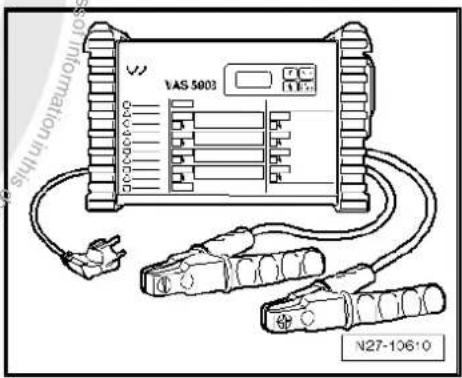
3.3 Battery charger VAS 5903 41
3.4 Battery charger VAS 5906 53
3.5 Midtronics INC 940 battery charger only for USA/Canada 55
3.6 Solar panel VAS 6102A 59
3.7 Totally discharged batteries 59
4 Cruise control system (CCS) 61
4.1 Activating and deactivating cruise control system (CCS) 61
90 - Gauges, instruments 62
92 - Windscreen wash/wipe system 63
1 Washer fluid line hose couplings 63
1.1 Windscreen and rear window washer system 63
1.2 Headlight washer system 64
2 Hose repair 65
2.1 General description 65
2.2 Repairing smooth pipe 65
2.3 Repairing corrugated pipe 65
3 Distinguishing features of jointless wiper blades 67
94 - Lights, bulbs, switches - exterior 68
1 Operation and safety notes for gas discharge bulbs 68
96 - Lights, bulbs, switches - interior 71
1 12 V socket 71
1.1 Removing and installing 12 V socket 71
1.2 Removing and installing socket illumination bulb L42 71
2 Cigarette lighter U1 72
2.1 General description 72
2.2 Assembly overview 73
2.3 Removing and installing cigarette lighter socket 74
2.4 Removing and installing cigarette lighter illumination bulb L28 76
97-Wiring 78
1 Vehicle diagnostic, testing and information systems 78
1.1 Connecting vehicle diagnostic tester 78
1.2 Connecting vehicle diagnostic tester Golf Model Year 1998 - 2003 80
2 Repairing wiring harnesses and connectors 81
2.1 Wiring harness repair set 81
2.2 Tool descriptions 82
2.3 General notes concerning repairs to vehicle electrical system 85
2.4 Repairs to wiring harnesses 87
2.5 Repairs to contact housings and connectors 97
2.6 Releasing and dismantling contact housings 102
3 Contact surface cleaning set VAS 6410 108
3.1 Using contact surface cleaning set VAS 6410 108
4 Renewing Lambda probe 115
4.1 Renewing LSF Lambda probe (4-pin) 115
4.2 Renewing LSU Lambda probe (6-pin) 116
4.3 Types of protective tube on uniform Lambda probes 117

27 – Starter, current supply, CCS
1 Battery

WARNING
Danger of injury! Observe warning notices and safety regulations ⇒ page 2 !

Caution
To prevent damage to the battery and vehicle, the following should be observed concerning types of battery page 1.
1.1 Fundamentals for batteries
To ensure long use of the battery, the battery must be checked, serviced and maintained according to the specifications in this manual.
Apart from supplying energy for starting the engine, the battery has other tasks: it acts as a buffer and supplies electrical energy to the complete electrical onboard supply of the vehicle.
1.2 Types of batteries

General notes

Caution
The description for the following batteries is for maintenance-free batteries. No stickers may be removed and do not replenish with distilled water. Only perform a visual check. Refer to chapter, Checking battery page 5.
1.2.1 Battery with magic eye
This is a maintenance-free battery with liquid electrolyte (wet battery).

Caution
No stickers may be removed and do not replenish with distilled water. Only perform a visual check. Refer to chapter, Checking battery page 5.

WARNING
Batteries where the magic eye is colourless or light yellow must not be checked or charged. Do not slave/jump start the vehicle!
Danger of explosion when checking and charging or slave/jump starting.
These batteries must be renewed.
This battery is equipped with a magic eye. The magic eye provides information concerning the level of the electrolyte and the charge state of the battery via a coloured display. Checking colour display of the magic eye page 6
1.2.2 Absorbent glass mat battery
Maintenance-free battery with a contained electrolyte and no magic eye.
Lead-acid battery where the electrolyte is contained within a microscopic glass mat (AGM). The battery is sealed and fitted with valves.
AGM is the abbreviation for absorbent glass mat.
Due to containment of the electrolyte, this type of battery may not have a magic eye. Absorbent glass mat batteries are identified by the abbreviation AGM on the battery.

Note
Always replace an absorbent glass mat battery with another absorbent glass mat battery.
1.3 Warning notices and safety regulations
1.3.1 Dangers when handling vehicle batteries
Recognition and avoidance of dangers
Batteries can be dangerous. These dangers can be avoided when the warnings on the battery, in the operating manual and in ELSA are observed.

WARNING
Untrained personnel e.g. apprentices, trainees etc. may only work on batteries when supervised by a vehicle mechanic/foreman or vehicle electrician/foreman.
Acid is highly corrosive. There is a considerable danger of acid burns if personnel do not handle batteries correctly. Therefore suitable measures must be taken to ensure that equipment/solutions etc. are available to neutralize acid burns. A suitable solution is: e.g. a soap solution.
If electrolyte leaks from a battery it may cause skin burns or acid corrosion and rusting on the vehicle. This may damage safety relevant components on the vehicle.
The gas which forms when charging and the gas which may escape through vent valves is explosive. In extreme cases a battery may explode if the battery is not handled correctly.
♦ Batteries must be renewed where the magic eye is colourless or light yellow. They must not be checked or charged and do not slave/jump start. Danger of explosion when checking and charging or slave/jump starting.
It is prohibited to cause sparks through grinding, welding, cutting operations and use naked lights in the vicinity of batteries. Smoking is also prohibited. Sparks generated by electrostatic charging must also be avoided. Always touch the vehicle body before touching the battery.
Only work on batteries in well ventilated and suitable rooms.
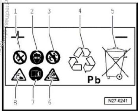
1.3.2 Safety markings on battery
Safety markings on battery
-
- Fires, sparks, naked flames and smoking are prohibited when handling batteries. Avoid sparks as well as electrostatic discharge when working with cables and electrical units. Avoid short circuits. Therefore never lay a tool on a battery.
-
- Wear eye protection before commencing work on battery.
-
- Keep children away from acid and batteries.
-
- Disposal: old batteries are classed as hazardous waste. They may only be disposed of through a suitable collection centre and only in accordance with respective legislation.
-
- Never dispose of old batteries in household waste system!
-
- There is a danger of an explosion when working with batteries. A highly explosive gas is produced when batteries are charged.
-
- Always follow instructions on battery, in ELSA "Electrical System, General Information" and in owner's manual.
-
- Battery acid is very caustic; therefore wear eye protection and gloves when working with batteries. Do not tilt battery. Acid can leak out of the gas vents of some batteries.
1.4 Battery terminal connection

Caution
To prevent damage to the battery clamps and battery terminals, the following should be observed:
◆ The battery clamps should only be fitted by hand and without using force.
◆ Battery terminals should not be coated with grease.
◆ The battery clamps should be fitted so that the battery terminal is either flush with the clamp or protruding from it.
Once the battery clamps have been tightened to the specified torque, the threaded connections should not be tightened any further.

2 Checking battery

WARNING
Danger of injury! Observe warning notices and safety regulations ⇒ page 2 !

Caution
To prevent damage to the battery and vehicle, the following should be observed concerning types of battery page 1.
2.1 Checking the various types of batteries
2.1.1 Checking battery with magic eye

WARNING
Danger of injury! Observe warning notices and safety regulations ⇒ page 2!
Carry out procedure in sequence as follows:
- Visual check page 6
- Check colour display of „3-colour“ magic eye ⇒ page 6 or „2-colour“ magic eye ⇒ page 7.

WARNING
Batteries where the magic eye is colourless or light yellow must not be checked or charged. Do not slave/jump start the vehicle!
Danger of explosion when checking and charging or slave/jump starting
These batteries must be renewed.
- Perform a battery load test using battery tester with printer -VAS 5097 A- page 9.
- Battery test with battery tester with printer -VAS 6161- page 14.
- Depending on the result of the battery test, "perform current draw test" page 22.
2.1.2 Absorbent glass mat battery
Carry out procedure in sequence as follows:
- Visual check page 6
- Perform a battery load test using battery tester with printer -VAS 5097 A- page 9.
- Battery load test with battery tester with printer -VAS 6161- page 14

- Depending on the result of the battery test, "perform current draw test" page 22.
2.2 Visual check

WARNING
Danger of injury! Observe warning notices and safety regulations page 2!
It is essential to visually inspect the external condition, to check the terminals and to ensure proper attachment of the battery before performing extensive tests.

Caution
◆ The battery will be damaged if the battery is not secured correctly.
♦ Vibrations shorten the life of the battery, there is a danger of an explosion, the cell plates may be damaged and the clamping bracket may damage the battery housing.
◆ Check battery is securely seated, if necessary tighten securing bolt to specified torque.
Performing this test establishes:
If battery housing is damaged Electrolyte can leak out if the housing is damaged. If battery acid leaks out, serious damage to the vehicle could be caused. Treat components affected by leaked battery acid immediately with acid neutraliser or a soap solution.
Check whether the battery terminals (battery wire connections) are damaged. The necessary contact on the battery clamps cannot be guaranteed if the battery terminals are damaged. When connecting the battery clamps, tighten the battery clamps to torque specified in this workshop manual „Electrical system“ for the respective vehicle. If the battery clamps are not correctly seated and tightened, the wiring may burn. Which will cause malfunctions in the electrical system. Therefore it can no longer be guaranteed that the vehicle will function correctly.
2.3 Checking colour display of magic eye
2.3.1 Checking colour display of „3-colour“ magic eye

WARNING
Danger of injury! Observe warning notices and safety regulations page 2!

General information on magic eye:
Applies for all batteries with „1J0“, „7N0“ and „3B0“ indexes in original equipment and for all replacement batteries 191 915 105 AB and from „000 915 105 AX“ index.
The magic eye provides information concerning electrolyte level and the charge state of the battery.
Before carrying out a visual check, tap the magic eye lightly and carefully using the handle of a screwdriver. The air bubbles, which can influence the display, will dissipate when doing this. The colour display of the magic eye will therefore be more accurate.

Note
Air bubbles can form below the magic eye particularly when the battery is being charged, including during normal vehicle operation. These distort the colour displayed by the magic eye.
Because the magic eye is located in only one cell, the display applies only to this cell. An exact determination of the battery condition is only possible through a battery load test page 9 or a battery test page 14.
The magic eye can be located at various positions on the battery.
Three different colour displays are possible:
◆ »Green«, battery is charged sufficiently.
- »Black«, battery partly discharged, charge state < 65 % or completely discharged
◆ »Colourless or light yellow«, battery must be renewed.

WARNING
Batteries where the magic eye is colourless or light yellow must not be checked or charged. Do not slave/jump start the vehicle!
Danger of explosion when checking and charging or slave/jump starting
These batteries must be renewed.
2.3.2 Checking colour display of „2-colour" magic eye

WARNING
Danger of injury! Observe warning notices and safety regulations page 2!
General information on magic eye:
For batteries from „5K0“ index in original equipment and for replacement batteries 191 915 105 AC from „000 915 105 DX“ index, the »green« colour display for charge state display has been discontinued. The introduction of the new colour display will take place gradually, i.e. there will be a transition period for both displays. In the future, the only remaining colours will be »black« or »colourless or light yellow«.
The magic eye provides information concerning the electrolyte level of the battery.
The charge state of the battery can no longer be read from the magic eye, a battery load test must be carried out for this ⇒ page 9
Before carrying out a visual check, tap the magic eye lightly and carefully using the handle of a screwdriver. The air bubbles, which can influence the display, will dissipate when doing this. The colour display of the magic eye will therefore be more accurate.

Note
Air bubbles can form below the magic eye particularly when the battery is being charged, including during normal vehicle operation. These distort the colour displayed by the magic eye.
Because the magic eye is located in only one cell, the display applies only to this cell. An exact determination of the battery condition is only possible through a battery load test page 9.
◆ The magic eye can be located at various positions on the battery.
Three different colour displays are possible:
◆ »Black«, electrolyte level is OK.
◆ »Colourless or light yellow«, electrolyte level too low. The battery must be renewed.

WARNING
Batteries where the magic eye is colourless or light yellow must not be checked or charged. Do not slave/jump start the vehicle!
Danger of explosion when checking and charging or slave/jump starting
These batteries must be renewed.
2.4 Battery tester with printer -VAS 5097 A-

WARNING
Danger of injury! Observe warning notices and safety regulations ⇒ page 2 !
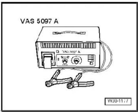
It is not necessary to remove or disconnect battery when using battery tester with printer -VAS 5097 A-.
Battery tester with printer -VAS 5097 A- can be used to test 12 V starter batteries.
♦ 80 - 520 A low-temperature test current according to DIN (Deutsche Industrie Norm (German Industrial Standard)) ^1)
◆ 95 - 574 A cold cranking current according to IEC (International Engineering Consortium)
◆ 136 - 855 A cold cranking current according to EN/ SAE (European Norm/Standard of Automotive Engineers)
1) Batteries with cold cranking current higher than 499 A according to DIN (e.g. 520 A, 580 A or 600 A) can be temporarily tested using setting for 499 A according to DIN.
For test purposes the battery is loaded with a current which is similar to the starting current required to start the vehicle. The battery is assessed on this loading and the result is printed out.

Note
Observe the instruction manual of Battery tester with printer -VAS 5097 A- or the sticker Brief instructions for battery tester with printer -VAS 5097 A- on the unit or table: Cold cranking current page 11.
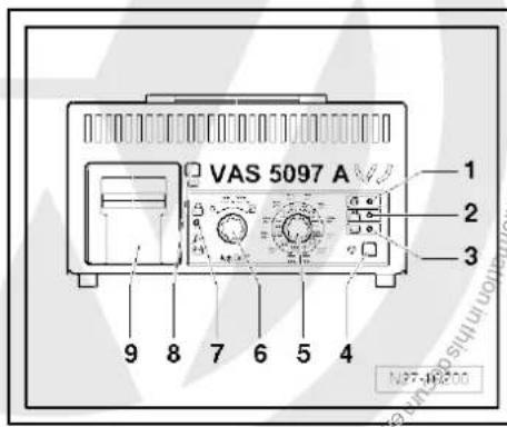
2.4.1 Description of battery tester with printer -VAS 5097 A-
Battery tester with printer -VAS 5097 A-
1 - Green LED, „unit operating“
2 - Red LED, "unit reverse-polarity connected"
3 - Red LED, „battery cannot be tested“, recharge battery.
4 - Start button
5 - Cold cranking current selection switch
6 - ON/OFF and functions switch
7 - Selection switch (battery tester to pick-off point on battery/external test point in engine compartment)
8 - Paper feed button
9 - Printer

2.4.2 Performing battery load test using battery tester with printer -VAS 5097 A-

WARNING
Danger of injury! Observe warning notices and safety regulations page 2!
Special tools and workshop equipment required
◆ Battery tester with printer -VAS 5097 A-

Note
Observe technical product information TPI 2012182 for battery tester with printer -VAS 5097 A-.
Performing battery load test:

WARNING
Batteries where the magic eye is colourless or light yellow must not be checked or charged. Do not slave/jump start the vehicle!
Danger of explosion when checking and charging or slave/jump starting
These batteries must be renewed.

Note
The battery must have a temperature of at least 10^ C.
- Switch off ignition and all electrical consumers.
- Check magic eye on batteries with magic eye page 5.
- Check low-temperature test current in amperes (A) according to DIN from indications on battery or set setting range on battery tester with printer -VAS 5097 A- according to table "2.4.3 Table: cold cranking current", page 11.

Note
If the battery values are shown in IEC or EN/SAE instead of DIN then convert figures using table
⇒ „2.4.3 Table: cold cranking current“, page 11 or using table on unit.
- Select low-temperature test current via low-temperature test current selection switch page 9.
- Select measuring range 80 - 379 A or 380 - 499 A with ON/OFF and functions switch page 9.

Note
Batteries with cold cranking current higher than 499 A according to DIN (e.g. 520 A, 580 A or 600 A) can be temporarily tested using setting for 499 A according to DIN.
- Connect red terminal „+“ of tester to positive terminal.
- Connect black terminal „-“ of tester to negative terminal.

Note
◆ Ensure test clamps have a good contact!
- Observe technical product information TPI 2012182 for battery tester with printer -VAS 5097 A-.
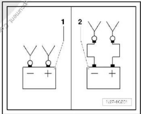
- Select point of connection of test terminals with selection switch page 9.
1 - Connected directly to battery
2 - Connected to external test points in engine compartment
- Check that the figures given on the battery are correct for the settings on the battery tester.
- Press start test button page 9.
The green LED lights up page 9. The test program runs through automatically. The test result is printed out by the printer page 12. If the unit does not start (LED does not light up, no print out), recharge battery page 25 and test again.
- Switch off unit page 9.
- Remove test terminals.

Note
◆ The test is completed after about 20 seconds.
◆ The result of the test is printed out by the printer.
◆ Perform test once only. Repeating the test falsifies the result.
◆ The tester requires approx. 30 minutes to cool down before it is ready for the next test.
2.4.3 Table: cold cranking current
| Cold cranking current in A | |||
| EN/ SAE | IEC | DIN | |
| 136 – 17 | 95 – 124 | 80 – 104 | |
| 178 – 219 | 125 – 154 | 105 – 129 | |
| 220 – 261 | 155 – 184 | 130 – 154 | |
| 262 – 303 | 185 – 214 | 155 – 179 | |
| 304 – 345 | 215 – 244 | 180 – 204 | |
| 346 – 387 | 245 – 274 | 204 – 229 | |
| 388 – 429 | 275 – 304 | 230 – 254 | |
| 430 – 471 | 305 – 334 | 255 – 279 | |
| 472 – 513 | 335 – 364 | 280 – 304 | |
| Cold cranking current in A | |||
| EN/ SAE | IEC | DIN | |
| 514 – 555 | 365 – 394 | 305 – 329 | |
| 556 – 597 | 395 – 424 | 330 – 354 | |
| 598 – 639 | 425 – 454 | 355 – 379 | |
| 640 – 657 | 455 – 464 | 380 – 389 | |
| 658 – 675 | 465 – 474 | 390 – 399 | |
| 676 – 693 | 475 – 484 | 400 – 409 | |
| 694 – 711 | 485 – 494 | 410 – 419 | |
| 712 – 729 | 495 – 504 | 420 – 429 | |
| 730 – 747 | 505 – 514 | 430 – 439 | |
| 748 – 765 | 515 – 524 | 440 – 449 | |
| 766 – 783 | 525 – 534 | 450 – 459 | |
| 784 – 801 | 535 – 544 | 460 – 469 | |
| 802 – 819 | 545 – 554 | 470 – 479 | |
| 820 – 837 | 555 – 564 | 480 – 489 | |
| 838 – 855 | 565 – 574 | 490 - 499^2) ^1) | |
2) 1) Batteries with cold cranking current higher than 499 A according to DIN (e.g. 520 A, 580 A or 600 A) can be temporarily tested using setting for 499 A according to DIN.
2.4.4 Evaluating test result of battery load test
Because of the high load on the battery during this test (a high current flows) the battery voltage drops.
If the battery is OK, the voltage value drops only to the minimum voltage.
If the battery is defective or has a low charge, the battery voltage quickly drops below the minimum voltage.
◆ After the test is completed, this low voltage value remains over a longer period, and the voltage increases very slowly again.
◆ Perform test once only. Repeating the test falsifies the result.
The tester requires approx. 30 minutes to cool down before carrying out another test or testing another battery to ensure the results are not falsified.
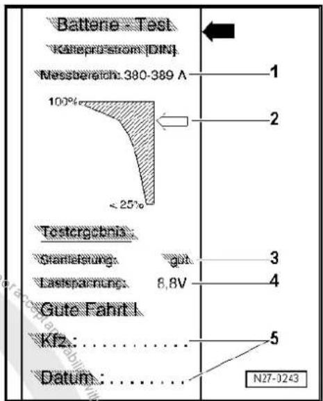
2.4.5 Comments concerning test print out
1 - Measuring range selected on tester
2 - Diagram -arrow- indicates battery condition.
3 - Test result
4 - Battery voltage during load test.
5 - Vehicle data and date Must be completed by test personnel

Note
◆ The test printout is required for warranty claims.
◆ Perform test once only. Repeating immediately the test falsifies the result.
2.4.6 Assessing test results
| Printout from battery tester | Measure to be performed |
| Starting capability very good | Battery OK. |
| Starting capability good | Battery OK. |
| Starting capability sufficient | Evaluation by carrying out a current draw test when charging ⇒ page 22 |
| Starting capability poor | Evaluation by carrying out a current draw test when charging ⇒ page 22 |
| Starting capability very poor | Evaluation by carrying out a current draw test when charging ⇒ page 22 |
| Cannot be tested | Perform battery charging ⇒ page 25 and repeat test. |
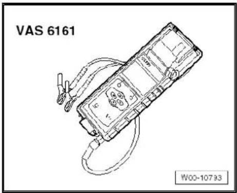
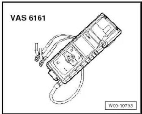
2.5 Battery tester with printer -VAS 6161-
General description

WARNING
Danger of injury! Observe warning notices and safety regulations → page 2 !
It is not necessary to remove or disconnect battery when using battery tester with printer -VAS 6161-.
The battery tester with printer -VAS 6161- does not load the battery any more. It works on the principle of dynamic conductance acquisition.
Every battery type is stored in the tester.
Data can be stored on an SD card.
The battery tester with printer -VAS 6161- can be updated via an interface or an SD card, so that battery data from Volkswagen are always up to date.
The integrated temperature sensor improves measurement quality.
A 2D scanner is available as an option to read data directly from the bar code of the battery.

Note
Observe the operating manual of the battery tester with printer -VAS 6161-.
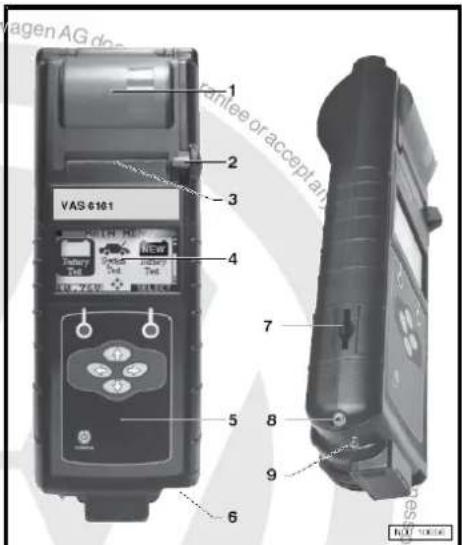
2.5.1 Description of battery tester with printer -VAS 6161-
1 - Integrated printer
2 - Operating lever for paper compartment
3 - Paper slot
4 - LCD screen with main menu
5 - Control panel with On/Off button
6 - Connection for battery test cable
7 - Memory card slot
8 - Infrared temperature sensor
9 - Data transmitter for PC
2.5.2 Perform battery test with battery tester with printer -VAS 6161-.

WARNING
Danger of injury! Observe warning notices and safety regulations ⇒ page 2 !
Special tools and workshop equipment required
◆ Battery tester with printer -VAS 6161-
Performing battery test:

WARNING
Batteries where the magic eye is colourless or light yellow must not be checked or charged. Do not slave/jump start the vehicle!
Danger of explosion when checking and charging or slave/jump starting
These batteries must be renewed.
- Switch off ignition and all electrical consumers.
- Check magic eye on batteries with magic eye ⇒ page 5.
- Switch on unit.
- Connect red terminal „+“ of tester to positive terminal.
- Connect black terminal „-“ of tester to negative terminal.

Note
Ensure test clamps have a good contact!
- Select one of the following functions.
◆ Maintenance test (only in new cars before registration, in stationary and stock maintenance programme → page 16)
◆ Service test ⇒ page 16
◆ Guarantee test ⇒ page 17

Note
◆ The test is completed after about 10 seconds.
◆ The result of the test is printed out by the printer.
◆ The tester requires no cooling phase before it is ready for the next measurement.
2.5.3 Performing maintenance test

WARNING
Batteries where the magic eye is colourless or light yellow must not be checked or charged. Do not slave/jump start the vehicle!
Danger of explosion when checking and charging or slave/jump starting
These batteries must be renewed.
- Select „Maintenance test“ in the menu.
- Connect scanner.

Note
If no scanner is available, write vehicle identification number on test printout by hand.
- Scan in vehicle identification number.
- Select „On battery terminal“ or „On jump-start point“.
- Scan in barcode or select type and manufacturer manually in menu.
- Measure temperature. Hold temperature sensor about 5 cm above terminal connection until temperature stabilises.
- Start test.
- Print out test log if necessary.
2.5.4 Perform service test

WARNING
Batteries where the magic eye is colourless or light yellow must not be checked or charged. Do not slave/jump start the vehicle!
Danger of explosion when checking and charging or slave/jump starting
These batteries must be renewed.
- Select „Service test“ in the menu.
- Select „On battery terminal“ or „On jump-start point“.
- Select vehicle type.
- Measure temperature. Hold temperature sensor about 5 cm above one battery terminal until temperature stabilises.

2.5.5 Perform guarantee test

WARNING
Batteries where the magic eye is colourless or light yellow must not be checked or charged. Do not slave/jump start the vehicle!
Danger of explosion when checking and charging or slave/jump starting
These batteries must be renewed.
- Select „Guarantee test“ in the menu.
- Select „In vehicle“ or „Outside vehicle“.
- Select „On battery terminal“ or „On jump-start point“.
- Select vehicle type.
- Measure temperature. Hold temperature sensor about 5 cm above one battery terminal until temperature stabilises.
- Select battery type „Normal“, „AGM“, „2*6V“ or „Gel“ or scan in.
- Select battery capacity or scan in.
- Start test.
- Print out test log if necessary.
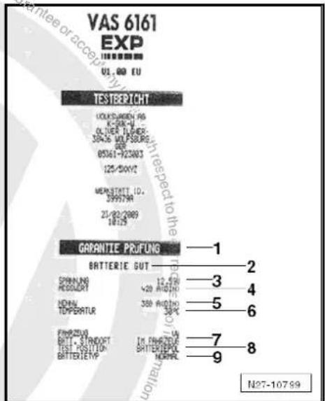
2.5.6 Comments concerning test print out
1 - Check type.
2 - Battery test result
3 - Measured voltage
4 - Measured cold start value of battery.
5 - Nominal cold start value of battery selected on tester.
6 - Measured temperature of battery.
7 - Fitting location of battery
8 - Position of battery clamp selected on tester
9 - Selected battery technology.

Note
The test printout is required for warranty claims.
2.5.7 Assessing test results
Evaluating battery test results for guarantee and service tests
| Battery test results | Measures |
| Battery OK | No measures on battery |
| Battery test results | Measures |
| Battery OK - recharge. | Charge battery page 25 . In case of discharging, look for fault |
| Perform current draw test | Perform current draw test page 22 . Fully charge battery page 25 and repeat test. |
| Renew battery. | Disconnect battery and repeat test. The result „Renew battery“ may be caused by a weak cable contact. |
| Battery cell defective - renew. | Renew battery. |
| Check connection. | Connect cable directly to battery and not to jump start terminal. |
Evaluating battery test results for maintenance test
| Battery test results | Measures |
| Battery OK | No measure |
| Charge battery immediately. | Charge battery fully page 25 . |
| Mark as defective. | Mark as defective. |
| Check tester connection. | Disconnect battery and repeat test. The result „Check tester connection“ may be caused by a weak cable contact. |
| Check connection. | Connect cable directly to battery and not to jump start terminal. |
| Noises | Wait until measured value appears on display. |
2.6 Midtronics -MCR340V- battery tester only for USA/Canada vehicles
General description page 18
Perform battery test with Midtronics -MCR340V- battery tester page 19.
Dealing with problems with Midtronics -MCR340V- battery tester ⇒ page 21
2.6.1 General description

WARNING
Danger of injury.
Before working on the battery, read through the warning and safety regulations carefully, and comply with them page 2.
Dispose of electrolyte (mixture of sulphuric acid and water) safely! Waste electrolyte is only allowed to be disposed of at appropriately indicated collecting points. Comply with the locally applicable disposal guidelines.
Do not test batteries that are liberating gas. Otherwise, there is a danger of explosion.

WARNING
Batteries where the magic eye is colourless or light yellow must not be checked or charged. Do not slave/jump start the vehicle!
Danger of explosion when checking and charging or slave/jump starting
These batteries must be renewed.

Note
To prevent damage to the battery and vehicle, note the types of battery and the remarks given page 1.
Batteries in VW vehicles are only allowed to be tested with battery testers approved by VW. In the USA/Canada, it is permitted for the Midtronics -MCR340V- battery tester to be used.
Read all the information about safety, setup and operation in the operating instructions for the Midtronics -MCR340V- battery tester and follow the instructions to the letter.
Refer to Self-study programme No. ; Vehicle batteries for more information.
The following charging and analysis procedures apply to all batteries, all battery installation locations (engine compartment or luggage compartment) and battery purposes (starter battery or second/convenience battery).
Always comply with the safety regulations, the regulations for setting up the battery tester, the display menu/display buttons, LEDs and the operating procedures described in the operating manual MCR340V.

Note
Observe and comply with all subsections, remarks and references to the vehicle and battery type, etc. to be tested.
2.6.2 Performing battery test with Midtronics - MCR340V- battery tester
Prerequisites:

WARNING
Before working on the battery, read through the warning and safety regulations carefully, and comply with them page 2.
Batteries where the magic eye is colourless or light yellow must not be checked or charged. Do not slave/jump start the vehicle!
Danger of explosion when checking and charging or slave/jump starting
These batteries must be renewed.
- Read general description page 18.
- Perform visual check page 6.
- Open bonnet or cover for other installation location of battery.
- Determine whether battery type is „Standard“ or „AGM“.
- Remove covers from battery positive and negative terminals.
- Use wing covers or other kinds of cover before you use equipment in engine compartment or interior.
- Close all doors.

Note
◆ Battery temperature must be at least 10 °C.
For additional information, refer to the operating manual INC 940.
Perform test:

WARNING
Batteries where the magic eye is colourless or light yellow must not be checked or charged. Do not slave/jump start the vehicle!
Danger of explosion when checking and charging or slave/jump starting
These batteries must be renewed.
- Switch off ignition and all electrical consumers.
- Check magic eye on batteries with magic eye page 5.
- Switch on tester.
- Connect red terminal „+“ of tester to positive terminal.
- Connect black terminal „-“ of tester to negative terminal.

Note
Ensure test clamps have a good contact!
- Select „In vehicle“ or „Outside vehicle“.
- Select „Warranty test“.

Note
Use the print function of the Midtronics -MCR340- tester if the test results are required for handling warranty applications.
- Select battery type „Standard“ or „AGM“.
- Make a note of the DIN value of the battery as shown on the battery sticker. If there is no DIN value on the sticker, make a note of the SAE value.
- Enter DIN value in tester and perform battery test operating manual MCR340V.
- If you are using SAE value, access „Miscellaneous“ menu and change from „DIN“ to „SAE“ ⇒ operating manual MCR340V.

Note
Always use DIN value from battery sticker! Otherwise, test result will be falsified.
2.6.3 Assessing test results
Results of battery test:
| Battery test results | Measures |
| Battery OK | None |
| Good - charge | Charge battery ⇒ page 55 . |
| Use Incharge | Charge battery ⇒ page 55 . |
| Renew battery. | Renew battery ⇒ Electrical system; Rep. gr. 27 ; Removing and installing battery |
| Battery cell defective | Renew battery ⇒ Electrical system; Rep. gr. 27 ; Removing and installing battery |
2.6.4 Dealing with problems with Midtronics - MCR340V- battery tester
Under certain circumstances, the display may show errors or messages according to status.
The most frequent display messages are listed below, together with suggested solutions.

Note
For messages not listed here, please refer to operating manual MCR340V.
| Display message | Measures |
| No display | - Check whether terminals of battery tester are firmly connected to battery terminals.- Check battery terminals are tightened according to regulations and do not have corrosion.- Charge battery page 55. |
| System noise | - Switch off all electrical consumers.- Wait until all electrical loads monitored by onboard supply control unit have switched off.- Remove ignition key.- Disconnect any suspect electrical equipment not connected to onboard supply as standard. |
Wait a few minutes and test again page 19.

Note
If you have performed test at jump-start point and message does not disappear, perform test directly on battery.
2.7 Current draw test

WARNING
Batteries where the magic eye is colourless or light yellow must not be checked or charged. Do not slave/jump start the vehicle!
Danger of explosion when checking and charging or slave/jump starting
These batteries must be renewed.

Note
◆ Ensure that the correct charging mode is set on the charger so that the current draw test is not falsified.
♦ VAS 5095 A ➞ page 26
♦ VAS 5900 ⇒ page 30
♦ VAS 5903 ⇒ page 41
To quickly ascertain the state of discharged batteries, the battery current draw test whilst charging helps to determine whether the battery must be replaced or fully recharged.

Note
For battery tester with printer -VAS 6161-, the current draw test must always be performed when the test result „Perform current draw test“ appears on the display.
The current draw test must be carried out when the test result with battery tester with printer -VAS 5097A- is as follows:
1 - Starting output sufficient
2 - Starting output poor
3 - Starting output very poor
4 - Cannot be tested – charge battery and repeat test.
- and when the tester will not switch on (no LED, no printout)
Depending on the test result page 13 with battery tester with printer -VAS 5097A-, further procedures or tests may be required before making a final decision on the condition of the battery.
Performing a current draw test whilst charging a battery will quickly establish whether a partly or fully discharged battery page 59 can be recharged to return it to a serviceable condition.
Test requirements
When charging a battery, battery temperature must be at least ≥ +10^ .
The charger must be capable of outputting a charge current of at least 30 A, as for example with VAS 5095A, VAS 5900, VAS 5903
The battery's current draw must be measured with a current pick-up clamp, e.g. VAS 5051B/7, when charging with battery charger -VAS 5095A-. Battery charger -VAS 5900- and battery charger -VAS 5903- display the current draw on the unit.
- Connect battery to battery charger and start charging sequence.
- Measure charging current of battery after 5 minutes.
Test result:
If the current draw A is higher than 10 % of the nominal capacity (e.g. >6.1 A for a 61 Ah battery), fully charge battery and test again.

Note
For Eos with two 6V absorbent glass mat batteries, the charge current must only be 5 % higher than the nominal capacity of the battery. Example for Eos: the 50 Ah battery must have a charge current higher than 2.5 A after 5 minutes of starting the charging sequence.
- Fully charge the battery when the charge current is higher than 10% of the nominal capacity (observe exception for Eos in above note).
- Perform battery test after allowing battery to rest for two hours page 9.
If the charge current, in amperes, lies below 10 % of the nominal capacity after 5 minutes of starting the charging sequence (5 % for the 2 x 6 volt batteries in Eos) (example for 50 Ah battery < 5A), renew battery. For Guarantee and ex-gratia cases: complete battery test sheet and keep it with the battery.
2.8 Checking no-load voltage of battery on stock and stored vehicles

WARNING
Danger of injury! Observe warning notices and safety regulations page 2!

Note
The no-load voltage test may only be carried out to assess the condition of the battery on stock and stored vehicles within the framework of prescribed maintenance.
The no-load test serves to determine whether a battery on a stock or stored vehicle requires recharging Maintenance tables „Service for stock and stored vehicles“.
Special tools and workshop equipment required
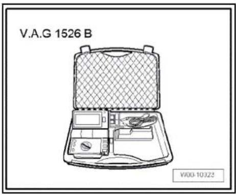
◆ Hand multimeter -V.A.G 1526 B-
Test conditions
The battery must not have been charged or discharged within the last 2 days.
- Check battery no-load voltage with hand multimeter -V.A.G 1526 B-.
| No-load voltage | Charge | Condition of battery |
| 11.60 V | 0 % | Discharged, no capacity Heavily discharged page 59 . |
| Measured value | Measure to be performed |
| No-load voltage ≥ 12.5 V | No-load voltage OK |
| No-load voltage < 12.5 V | Charging battery ⇒ page 25 |

3 Charging battery

WARNING
Danger of injury! Observe warning notices and safety regulations page 2!

Caution
To prevent damage to the battery and vehicle, the following should be observed concerning types of battery page 1.

WARNING
Batteries where the magic eye is colourless or light yellow must not be checked or charged. Do not slave/jump start the vehicle!
Danger of explosion when checking and charging or slave/jump starting
These batteries must be renewed.
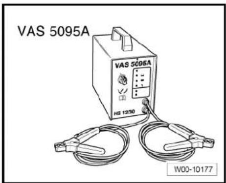
3.1 Battery charger -VAS 5095 A-
This chapter describes the basic functions of the battery charger -VAS 5095 A-. For additional information refer to operating instructions for battery charger -VAS 5095 A-.

Note
The effective charging current can not be read on these units. The charge current must be read externally using a pick-up clamp.
Observe ⇒ operating instructions for battery charger -VAS 5095 A-.
3.1.1 Description of battery charger -VAS 5095 A-
The battery charger -VAS 5095- is suitable for charging all 12V batteries supplied by Volkswagen.
The battery charger charges without peaks in amperage or voltage. This will not adversely effect the onboard electronics. The battery can remain in the vehicle while it is being charged and need not be disconnected.
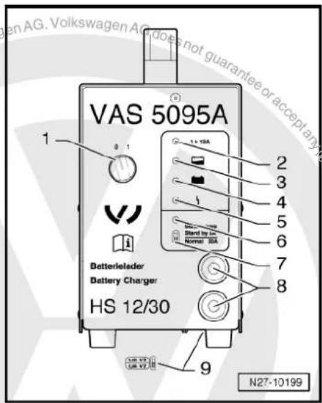
Battery charger -VAS 5095 A-
1 - ON / OFF switch (0 = charger OFF)
2 - Charging current indicator (I > 12 A)
3 - Charging current indicator, battery partially charged > 90 %
4 - Maintaining charge; lights up green when battery is fully charged
5 - Malfunction indicator
6 - Support mode indicator
7 - Support mode/normal mode changer-over switch
8 - Charger cable, red terminal „+“, black terminal „-“
9 - Battery type change-over switch (on base of charger unit)
3.1.2 Charging battery with battery charger - VAS 5095 A-

WARNING
Danger of injury! Observe warning notices and safety regulations page 2!
Special tools and workshop equipment required
◆ Battery charger -VAS 5095 A-

Caution
Always set battery type 2.4 V/C (volts/battery cell) when charging! This applies for all batteries.

Note
The battery must have a temperature of at least 10^ C.

WARNING
Batteries where the magic eye is colourless or light yellow must not be checked or charged. Do not slave/jump start the vehicle!
Danger of explosion when checking and charging or slave/jump starting
These batteries must be renewed.
- Switch off ignition and all electrical consumers.
- Check setting for battery type on type of battery switch page 25. Must be set to 2.4 V/C (volts/battery cell).
- Connect red terminal clamp „+“ of charger unit to positive terminal on battery.

Note
In vehicles with start/stop function and battery monitor control unit -J367- fitted, black terminal clamp "must be connected to body earth. Connecting it to battery negative terminal will cause start/stop system to malfunction.
- Connect black terminal clamp „-“ of battery charger to negative terminal.
- Switch on battery charger page 25.
The charging current indicators page 26 -2- and -3- light up yellow. When only the light emitting diode (LED) -3- lights up yellow, battery is partially discharged (approx. 90% ).
If the LED lights up green page 26 -4- the charger has switched to "maintaining charge". The battery is fully charged.
- Switch off charging unit page 25.
- Remove charger unit terminals from battery terminals.
3.1.3 Charging totally discharged battery with battery charger -VAS 5095 A

WARNING
Danger of injury! Observe warning notices and safety regulations ⇒ page 2 !
The charger unit automatically recognises totally discharged batteries and initiates a gentle charging procedure with a low charging current. The charging current is automatically adapted to suit the charge condition of the battery.

Note
◆ Observe notes in chapter ⇒ page 59.
Totally discharged batteries in vehicles before registration must be exchanged prior to delivery. Preliminary damage cannot be excluded.
◆ The battery voltage must be at least 0.6 V.

WARNING
Batteries where the magic eye is colourless or light yellow must not be checked or charged. Do not slave/jump start the vehicle!
Danger of explosion when checking and charging or slave/jump starting
These batteries must be renewed.
- Charge battery page 26.
3.1.4 Charging battery in support mode with battery charger -VAS 5095A-
General notes:
The support mode provides the onboard supply with power when the battery is removed or disconnected.
For further information, refer to the operating manual VAS 5095A.
The support mode is suitable in the following situations:
◆ Support mode of onboard supplies without installed battery
Power conservation when renewing the battery
◆ Ancillaries test without battery

WARNING
Danger of injury! Observe warning notices and safety regulations ⇒ page 2 !

WARNING
Batteries where the magic eye is colourless or light yellow must not be checked or charged. Do not slave/jump start the vehicle!
Danger of explosion when checking and charging or slave/jump starting
These batteries must be renewed.
- Switch off ignition and all electrical consumers.

Caution
The terminal polarity protection in operating mode „charging totally discharged batteries/support mode“ is not active. Connect battery charger terminal clamps correctly to battery terminals.
It can cause sparks through a short-circuit.
◆ Danger of explosion
◆ Ensure charger terminal clamps are seated securely.
Do not press START / STOP button when charger unit cables are connected incorrectly. The charger unit may be damaged.
- Remove battery.

Caution
When battery is removed, ensure there is no contact between terminal clamp connected to positive clamp and body earth. Also ensure there is no contact between battery clamps.
- Connect red terminal clamp „+“ to positive terminal of vehicle.

Note
In vehicles with start/stop function and battery monitor control unit -J367- fitted, black terminal clamp _w " must be connected to body earth. Connecting it to battery negative terminal will cause start/stop system to malfunction.
- Connect black terminal clamp „+“ to negative terminal of vehicle.
- Check setting for battery type on normal/support mode switch page 25. It must be switched on support mode.
- Check polarity of charger unit cables.
- Switch on battery charger.
The battery charger starts with support mode.
End battery support mode:
- Switch off battery charger.
- Disconnect black terminal clamp „-“ of charger unit from negative terminal of vehicle.
- Disconnect red terminal clamp „+“ of charger unit from positive terminal of vehicle.
– Pull charger plug out of battery charger.

3.1.5 Charging battery in maintenance mode with battery charger -VAS 5095 A-

WARNING
Danger of injury! Observe warning notices and safety regulations ⇒ page 2 !

WARNING
Batteries where the magic eye is colourless or light yellow must not be checked or charged. Do not slave/jump start the vehicle!
Danger of explosion when checking and charging or slave/jump starting
These batteries must be renewed.
In maintenance mode the battery charger -VAS 5095 A- ensures that the battery is charged correctly and is maintained in fully charged condition.
- Proceed as for charging battery page 26

Note
When a battery is being charged in maintenance mode and a electrical consumer draws current from the battery, the battery charger -VAS 5095 A- automatically compensates the charge.
◆ The maintenance mode can be continued for an unlimited period.
◆ The battery is always ready for use.
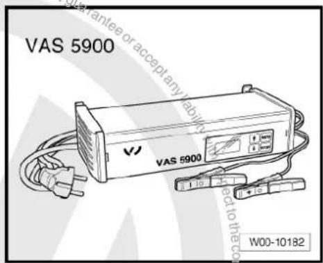
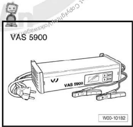
3.2 Battery charger -VAS 5900-

WARNING
Danger of injury! Observe warning notices and safety regulations page 2 !

WARNING
Batteries where the magic eye is colourless or light yellow must not be checked or charged. Do not slave/jump start the vehicle!
Danger of explosion when checking and charging or slave/jump starting
These batteries must be renewed.
This chapter describes the basic functions of the battery charger -VAS 5900-. For additional information refer to operating instructions for battery charger -VAS 5900-.

Note
◆ The effective charging current can be read directly on these charging units.
Observe operating instructions for battery charger -VAS 5900-.
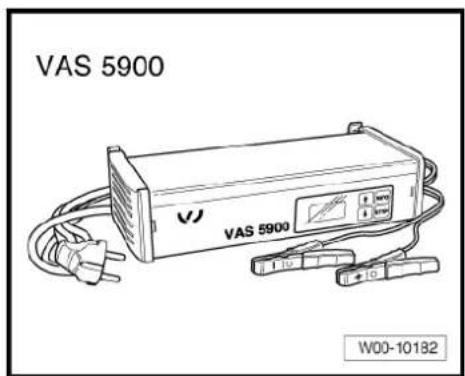
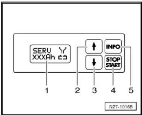
3.2.1 Description of battery charger -VAS 5900-
The battery charger -VAS 5900- is suitable for charging all 12V batteries supplied by Volkswagen.
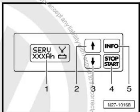
Battery charger -VAS 5900-
1 - Display
2 - Adjustment button "Up"
3 - Adjustment button „Down“ ↓
4 - START / STOP
5 - INFO
flowchart
graph TD
    A["SERV XXXAh"] --> B["1"]
    A --> C["2"]
    A --> D["3"]
    A --> E["4"]
    A --> F["5"]
    G["INFO"] --> H["↑"]
    G --> I["↓"]
    J["STOP START"] --> K["3"]
    style A fill:#f9f,stroke:#333
    style B fill:#ccf,stroke:#333
    style C fill:#ccf,stroke:#333
    style D fill:#ccf,stroke:#333
    style E fill:#ccf,stroke:#333
    style F fill:#ccf,stroke:#333
3.2.2 Charging battery with battery charger - VAS 5900-

WARNING
Danger of injury! Observe warning notices and safety regulations page 2!

WARNING
Batteries where the magic eye is colourless or light yellow must not be checked or charged. Do not slave/jump start the vehicle!
Danger of explosion when checking and charging or slave/jump starting
These batteries must be renewed.
Special tools and workshop equipment required
◆ Battery charger -VAS 5900-

Note
The battery must have a temperature of at least 10^ C.
- Switch off ignition and all electrical consumers.
- Connect charger plug to battery charger. The last selected type of battery will appear on display.
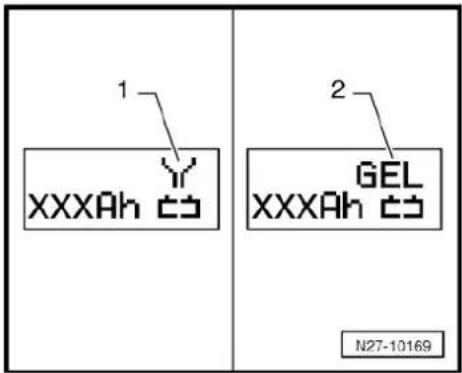
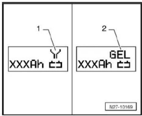
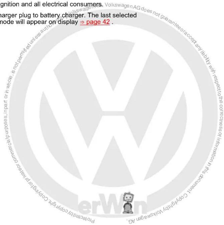
- Set battery to respective operating mode with INFO.
In the display the symbol -1- for „standard charge for wet batteries“ or symbol -2- for „standard charge for gel/absorbent glass mat batteries“ will appear.
- Set battery capacity (Ah) of battery for charging using respective button „Up“ □ or „Down“ □.
- Connect red terminal clamp „+“ to positive terminal on battery.

Note
In vehicles with start/stop function and battery monitor control unit -J367- fitted, black terminal clamp must be connected to body earth. Connecting it to battery negative terminal will cause start/stop system to malfunction.
- Connect black terminal clamp „-“ to negative terminal.
The charger unit recognises the voltage required for the connected battery (6 V, 12 V or 24 V) and initiates the charging sequence.
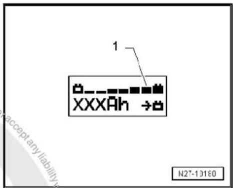
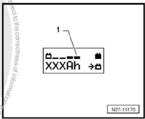
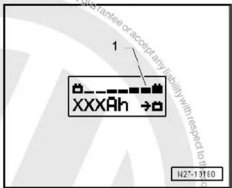
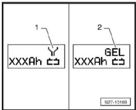
At a charge condition of approx. 80 - 85 % the battery charger switches to the „final charge“ mode. The fourth bar appears in display -1-. The battery is ready for use.
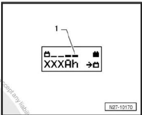
At a charge condition of 100 % all bars appear in display.

Note
In the battery type „standard charge“ the parallel use of consumers while charging is possible. The charging period will be longer.
The battery charger will switch to maintenance mode after about 1-7 hours, depending on type of battery. To achieve a 100 % charge the battery should remain connected for this period.
Possible faults and fault rectification
1 - Displayed battery voltage is not as per nominal voltage:
- Press respective button „Up“ □ or „Down“ □ until charging sequence starts.
2 - Displayed battery voltage is not as per nominal voltage – charging sequence already started:
- Press START / STOP twice.
- Press respective button „Up“ □ or „Down“ □ until charging sequence starts again.
3 - Battery charger does not detect a battery, when battery voltage is less than 2 V:
Display remains unchanged.
The battery type and ampere hours (Ah) as set is displayed.
Ending battery charging sequence:
- Press START / STOP.
- Disconnect black terminal clamp „-“ of charger from negative terminal.
- Disconnect red terminal clamp „+“ of charger from positive terminal on battery.
– Pull charger plug out of battery charger.
3.2.3 Charging battery in service mode with battery charger -VAS 5900-

WARNING
Danger of injury! Observe warning notices and safety regulations page 2!

Caution
The operating mode „service charge“ is not permitted on VW vehicles as the voltage peaks will damage the onboard electronics.
If there is a requirement to use "service charge" the battery must be disconnected from the onboard supply.

WARNING
Batteries where the magic eye is colourless or light yellow must not be checked or charged. Do not slave/jump start the vehicle!
Danger of explosion when checking and charging or slave/jump starting
These batteries must be renewed.

Caution
When charging always set the battery charger to the correct type of battery operating instructions for battery charger - VAS 5900- !
The "service mode" is suitable for:
◆ Wet batteries where the magic eye allows charging (magic eye black or green)
The operating mode „service charge (SERV)“ is only used on sulphated batteries. The battery is charged at a voltage of >14.4 V. This can result in a partial reduction of the sulphated layer. After charging, always check the colour of the magic eye before using the battery page 6.
Special tools and workshop equipment required
◆ Battery charger -VAS 5900-

Note
The battery must have a temperature of at least 10^ C.
- Switch off ignition and all electrical consumers.
- Connect charger plug to battery charger. The last selected operating mode will appear on display page 31.

- Set battery to respective battery type with INFO
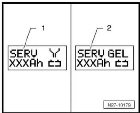
In the display, the symbol -1- for „Service charge for wet batteries“ or symbol -2- for „Service charge for gel/absorbent glass mat batteries“ will appear.
- Set battery capacity (Ah) of battery for charging using respective button „Up“ □ or „Down“ ↓.
- Connect red terminal clamp „+“ to positive terminal on battery.

Note
In vehicles with start/stop function and battery monitor control unit -J367- fitted, black terminal clamp „-“ must be connected to body earth. Connecting it to battery negative terminal will cause start/stop system to malfunction.
- Connect black terminal clamp „-“ to negative terminal.
The charger unit recognises the voltage required for the connected battery (6 V, 12 V or 24 V) and initiates the charging sequence.
At a charge condition of approx. 80 - 85 % of the battery voltage, the battery charger switches to the "final charge" mode. The fourth bar appears in display -1-. The battery is ready for use.

Note
The success of the „service charge“ depends on the severity of the sulphation of the battery
Possible faults and fault rectification:
1 - Displayed battery voltage is not as per nominal voltage:
- Press respective button „Up“ □ or „Down“ □ until charging sequence starts.
2 - Displayed battery voltage is not as per nominal voltage charging sequence already started.
- Press START / STOP twice.
- Press respective button „Up“ □ or „Down“ □ until charging sequence starts.
3 - Battery charger does not detect a battery, when battery voltage is less than 2 V:
Display remains unchanged.
The operating mode and ampere hours (Ah) as set are displayed.
Ending battery charging sequence:
- Press START / STOP.
- Disconnect black terminal clamp „-“ of charger from negative terminal.
- Disconnect red terminal clamp „+“ of charger from positive terminal on battery.
– Pull charger plug out of battery charger.
3.2.4 Charging totally discharged batteries with battery charger -VAS 5900-

WARNING
Danger of injury! Observe warning notices and safety regulations page 2!

WARNING
Batteries where the magic eye is colourless or light yellow must not be checked or charged. Do not slave/jump start the vehicle!
Danger of explosion when checking and charging or slave/jump starting
These batteries must be renewed.

Caution
The terminal polarity protection in operating mode „charging totally discharged batteries/support mode“ is not active. Connect battery charger terminal clamps correctly to battery terminals.
When charging always set the battery charger to the correct type of battery operating instructions for battery charger -VAS 5900-!
Totally discharged battery is not recognised by battery charger ⇒ page 59.
Do not press START / STOP button when charger unit cables are connected incorrectly. The charger unit may be damaged.
Batteries with a voltage of less than 2 volts will not be recognised automatically by battery charger -VAS 5900-.
Special tools and workshop equipment required
◆ Battery charger -VAS 5900-

Note
♦ Observe notes in chapter → page 59.
Totally discharged batteries in vehicles before registration must be exchanged prior to delivery. Preliminary damage cannot be excluded.
◆ The battery must have a temperature of at least 10 °C.
- Switch off ignition and all electrical consumers.
- Connect charger plug to battery charger. The last selected operating mode will appear on display page 31.

- Set battery to respective battery type with INFO.
In the display, the symbol -1- for „Service charge for wet batteries“ or symbol -2- for „Service charge for gel/absorbent glass mat batteries“ will appear.
- Set battery capacity (Ah) of battery for charging using respective button „Up“ □ or „Down“ □.
- Connect red terminal clamp „+“ to positive terminal on battery.

Note
In vehicles with start/stop function and battery monitor control unit -J367- fitted, black terminal clamp must be connected to body earth. Connecting it to battery negative terminal will cause start/stop system to malfunction.
- Connect black terminal clamp „-“ to negative terminal.
- Press START / STOP for approx. 5 seconds. The menu "charging totally discharged batteries/support mode" will be activated.
- Press respective button „Up“ □ or „Down“ □ to set respective battery voltage (6 V, 12 V or 24 V).

Note
If a button is not pressed within 5 seconds the charger will return to the main menu (select operating mode).
- Confirm the selected battery voltage with START0/GSTORM
Then follows the enquiry for "is charger cable terminal polarity correct". - Check polarity of charger unit cables.
- Confirm polarity of charger unit cables with START / STOP.
Charger will start charging sequence for totally discharged battery.
Ending battery charging sequence:
- Press START / STOP.
- Disconnect black terminal clamp „-“ of charger from negative terminal.
- Disconnect red terminal clamp „+“ of charger from positive terminal on battery.
– Pull charger plug out of battery charger.
3.2.5 Charging battery in support mode with battery charger -VAS 5900-
General notes:
The support mode provides the onboard supply with power when the battery is removed or disconnected.
For further information, refer to the operating manual VAS 5900.
The support mode is suitable in the following situations:
◆ Support mode of onboard supplies without installed battery
◆ Power conservation when renewing the battery
◆ Ancillaries test without battery

WARNING
Danger of injury! Observe warning notices and safety regulations ⇒ page 2!

WARNING
Batteries where the magic eye is colourless or light yellow must not be checked or charged. Do not slave/jump start the vehicle!
Danger of explosion when checking and charging or slave/jump starting
These batteries must be renewed.
- Switch off ignition and all electrical consumers.

Caution
The terminal polarity protection in operating mode „charging totally discharged batteries/support mode“ is not active. Connect battery charger terminal clamps correctly to battery terminals.
It can cause sparks through a short-circuit.
◆ Danger of explosion
◆ Ensure charger terminal clamps are seated securely.
Do not press START / STOP button when charger unit cables are connected incorrectly. The charger unit may be damaged.
- Remove battery.
- Connect charger plug to battery charger. The last selected operating mode will appear on display page 31.

Caution
When battery is removed, ensure there is no contact between terminal clamp connected to positive clamp and body earth. Also ensure there is no contact between battery clamps.
- Connect red terminal clamp „+“ to positive terminal of vehicle.

Note
In vehicles with start/stop function and battery monitor control unit -J367- fitted, black terminal clamp must be connected to body earth. Connecting it to battery negative terminal will cause start/stop system to malfunction.
- Connect black terminal clamp „+“ to negative terminal of vehicle.
- Press START / STOP for approx. 5 seconds. The menu "charging totally discharged batteries/support mode" will be activated.
- Press respective button „Up“ □ or „Down“ □ to set respective battery voltage (6 V, 12 V or 24 V).

Note
If a button is not pressed within 5 seconds the charger will return to the main menu (select operating mode).
- Confirm the selected battery voltage with START / STOP
Then follows the enquiry for "is charger cable terminal polarity correct".
- Check polarity of charger unit cables.
- Confirm polarity of charger unit cables with START / STOP
The battery charger starts with support mode.
End battery support mode:
- Press START / STOP
- Disconnect black terminal clamp „-“ of charger unit from negative terminal of vehicle.
- Disconnect red terminal clamp „+“ of charger unit from positive terminal of vehicle.
– Pull charger plug out of battery charger.
3.2.6 Charging battery in maintenance mode with battery charger -VAS 5900-

Note
When a battery is being charged in the maintenance mode and an electrical consumer draws current from the battery, the battery charger -VAS 5900- automatically compensates the charge.
◆ The maintenance mode can be continued for an unlimited period.
◆ The battery is always ready for use.
◆ Observe battery manufacture's maintenance instructions!

WARNING
Danger of injury! Observe warning notices and safety regulations page 2!


WARNING
Batteries where the magic eye is colourless or light yellow must not be checked or charged. Do not slave/jump start the vehicle!
Danger of explosion when checking and charging or slave/jump starting
These batteries must be renewed.
When the battery is fully charged the battery charger -VAS 5900-switches to maintenance mode.
- Proceed as for charging battery page 31.
At a charge condition of 100 % all bars appear in display.
3.3 Battery charger -VAS 5903-

WARNING
Danger of injury! Observe warning notices and safety regulations ⇒ page 2!

WARNING
Batteries where the magic eye is colourless or light yellow must not be checked or charged. Do not slave/jump start the vehicle!
Danger of explosion when checking and charging or slave/jump starting
These batteries must be renewed.
This chapter describes the basic functions of the battery charger -VAS 5903-. For additional information refer to operating instructions for battery charger -VAS 5903-.


Note
Observe operating instructions for battery charger -VAS 5903-.
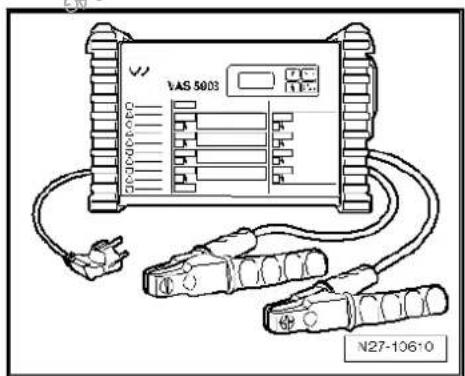
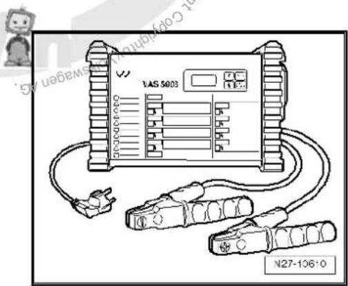
3.3.1 Description of battery charger -VAS 5903-
The battery charger -VAS 5903- is suitable for charging all 12V batteries supplied by Volkswagen.
Battery charger -VAS 5903-
1 - Display
2 - Adjustment button „Up“
3 - Adjustment button „Down“
4 - START / STOP
5 - INFO
flowchart
graph TD
    A["SERV XXXAh CD"] --> B["1"]
    A --> C["2"]
    A --> D["3"]
    A --> E["4"]
    A --> F["5"]
    G["INFO"] --> H["STOP START"]
    I["↑"] --> J["↓"]
3.3.2 Charging battery with battery charger - VAS 5903-

WARNING
Danger of injury! Observe warning notices and safety regulations page 2!

WARNING
Batteries where the magic eye is colourless or light yellow must not be checked or charged. Do not slave/jump start the vehicle!
Danger of explosion when checking and charging or slave/jump starting
These batteries must be renewed.
Special tools and workshop equipment required
◆ Battery charger -VAS 5903-

Note
The battery must have a temperature of at least 10^ C.
– Switch off ignition and all electrical consumers.
- Connect charger plug to battery charger. The last selected operating mode will appear on display page 42.
- Set battery to respective operating mode with INFO.
In the display the symbol -1- for „standard charge for wet batteries“ or symbol -2- for „standard charge for gel/absorbent glass mat batteries“ will appear.
- Set battery capacity (Ah) of battery for charging using respective button „Up“ □ or „Down“ ↓
- Connect red terminal clamp „+“ to positive terminal on battery.

Note
In vehicles with start/stop function and battery monitor control unit -J367- fitted, black terminal clamp must be connected to body earth. Connecting it to battery negative terminal will cause start/stop system to malfunction.
- Connect black terminal clamp „-“ to negative terminal.
The charger unit recognises the voltage required for the connected battery (6 V, 12 V or 24 V) and initiates the charging sequence.
At a charge condition of approx. 80 - 85 % the battery charger switches to the „final charge“ mode. The fourth bar appears in display -1-. The battery is ready for use.

At a charge condition of 100 % all bars appear in display.

Note
In the battery type „standard charge“ the parallel use of consumers while charging is possible. The charging period will be longer.
The battery charger will switch to maintenance mode after about 1-7 hours, depending on type of battery. To achieve a 100 % charge the battery should remain connected for this period.
Possible faults and fault rectification:
1 - Displayed battery voltage is not as per nominal voltage:
- Press respective button „Up“ □ or „Down“ □ until charging sequence starts.
2 - Displayed battery voltage is not as per nominal voltage - charging sequence already started:
- Press START / STOP twice.
- Press respective button „Up“ □ or „Down“ ↓ until charging sequence starts again.
3 - Battery charger does not detect a battery, when battery voltage is less than 2 V:
Display remains unchanged.
The battery type and ampere hours (Ah) as set is displayed.
Ending battery charging sequence:
- Press START / STOP.
- Disconnect black terminal clamp „-“ of charger from negative terminal.
- Disconnect red terminal clamp „+“ of charger from positive terminal on battery.
– Pull charger plug out of battery charger
3.3.3 Charging battery in refresh charge mode with battery charger -VAS 5903-

WARNING
Danger of injury! Observe warning notices and safety regulations page 2!

WARNING
Batteries where the magic eye is colourless or light yellow must not be checked or charged. Do not slave/jump start the vehicle!
Danger of explosion when checking and charging or slave/jump starting
These batteries must be renewed.


Caution
The operating mode „refresh charge“ is not permitted on VW vehicles as the voltage peaks will damage the onboard electronics.
If there is a requirement to use "refresh charge" mode the battery must be disconnected from the onboard supply.

Caution
When charging always set the battery charger to the correct type of battery operating instructions for battery charger - VAS 5903-!
The „refresh charge“ mode is suitable for:
◆ Wet batteries, where distilled water can be replenished.
Do not use operating mode „refresh charge“ with maintenance-free wet batteries.
The „refresh charge (refr)“ operating mode is only used on suspect defective batteries (e.g. sulphation). The battery will be charged to maximum specific gravity and the plates will be reactivated (dissipation of sulphur layer).
Special tools and workshop equipment required
◆ Battery charger -VAS 5900-

Note
The battery must have a temperature of at least 10^ C.
- Switch off ignition and all electrical consumers.
- Connect charger plug to battery charger. The last selected operating mode will appear on display ≥ page 42.
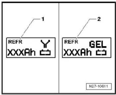
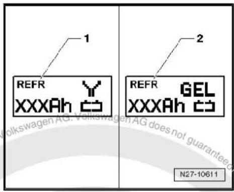
- Set battery to respective operating mode with INFO.
In the display the symbol -1- for „refresh charge for wet batteries“ or symbol -2- for „refresh charge for gel/absorbent glass mat batteries“ will appear.
- Set battery capacity (Ah) of battery for charging using respective button „Up“ □ or „Down“ □.
- Connect red terminal clamp „+“ to positive terminal on battery.

Note
In vehicles with start/stop function and battery monitor control unit -J367- fitted, black terminal clamp must be connected to body earth. Connecting it to battery negative terminal will cause start/stop system to malfunction.
- Connect black terminal clamp „-“ to negative terminal.
The charger unit recognises the voltage required for the connected battery (6 V, 12 V or 24 V) and initiates the charging sequence.
At a charge condition of approx. 80 - 85 % of the battery voltage, the battery charger switches to the „final charge“ mode. The fourth bar appears in display -1-. The battery is ready for use.

Note
The success of the „refresh charge“ depends on the severity of the sulphation of the battery.
Possible faults and fault rectification:
1 - Displayed battery voltage is not as per nominal voltage:
- Press respective button „Up“ □ or „Down“ □ until charging sequence starts.
2 - Displayed battery voltage is not as per nominal voltage - charging sequence already started:
- Press START / STOP twice.
- Press respective button „Up“ □ or „Down“ □ until charging sequence starts.
3 - Battery charger does not detect a battery, when battery voltage is less than 2 V:
Display remains unchanged.
The operating mode and ampere hours (Ah) as set are displayed.
Ending battery charging sequence:
- Press START / STOP.
- Disconnect black terminal clamp „-“ of charger from negative terminal.
- Disconnect red terminal clamp „+“ of charger from positive terminal on battery.
– Pull charger plug out of battery charger.
3.3.4 Charging totally discharged battery with battery charger -VAS 5903-

WARNING
Danger of injury! Observe warning notices and safety regulations ⇒ page 2 !

WARNING
Batteries where the magic eye is colourless or light yellow must not be checked or charged. Do not slave/jump start the vehicle!
Danger of explosion when checking and charging or slave/jump starting
These batteries must be renewed.

Caution
The terminal polarity protection in operating mode „charging totally discharged batteries/support mode“ is not active. Connect battery charger terminal clamps correctly to battery terminals.
When charging always set the battery charger to the correct type of battery → operating instructions for battery charger -VAS 5903-!
Totally discharged battery is not recognised by battery charger ⇒ page 59.
Do not press START / STOP button when charger unit cables are connected incorrectly. The charger unit may be damaged.
Batteries with a voltage of less than 2 volts will not be recognised automatically by battery charger -VAS 5903-.
Special tools and workshop equipment required
◆ Battery charger -VAS 5903-

Note
♦ Observe notes in chapter → page 59.
Totally discharged batteries in vehicles before registration must be exchanged prior to delivery. Preliminary damage cannot be excluded.
◆ The battery must have a temperature of at least 10 °C.
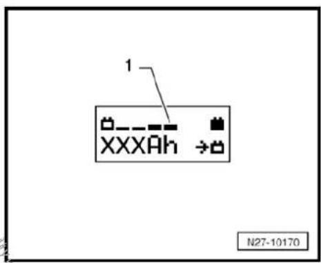
- Switch off ignition and all electrical consumers. - Connect charger plug to battery charger. The last selected operating mode will appear on display page 42.
- Set battery to respective operating mode with INFO.
In the display, the symbol -1- for „Service charge for wet batteries“ or symbol -2- for „Service charge for gel/absorbent glass mat batteries“ will appear.
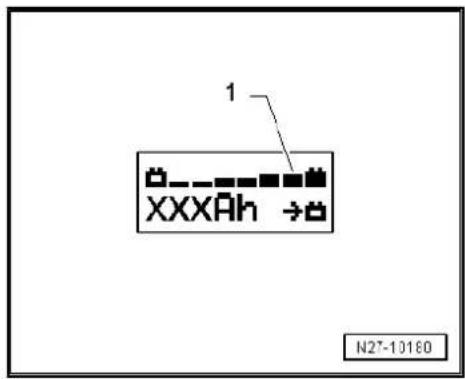
- Set battery capacity (Ah) of battery for charging using respective button „Up“ □ or „Down“ ↓.
- Connect red terminal clamp „+“ to positive terminal on battery.

Note
In vehicles with start/stop function and battery monitor control unit -J367- fitted, black terminal clamp must be connected to body earth. Connecting it to battery negative terminal will cause start/stop system to malfunction.
- Connect black terminal clamp „-“ to negative terminal.
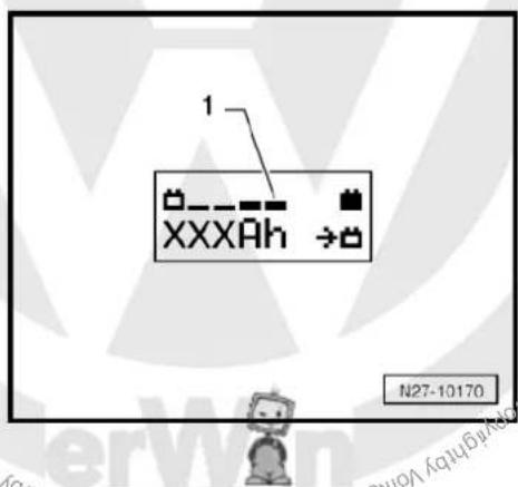
- Press START / STOP for approx. 5 seconds. The menu "charging totally discharged batteries/support mode" will be activated.
- Press respective button „Up“ □ or „Down“ □ to set respective battery voltage (6 V, 12 V or 24 V).

Note
If a button is not pressed within 5 seconds the charger will return to the main menu (select operating mode).
- Confirm the selected battery voltage with START / STOP.
Then follows the enquiry for "is charger cable terminal polarity correct".
- Check polarity of charger unit cables.
- Confirm polarity of charger unit cables with START / STOP.
Charger will start charging sequence for totally discharged battery.
Ending battery charging sequence:
- Press START / STOP.
- Disconnect black terminal clamp „-“ of charger from negative terminal.
- Disconnect red terminal clamp „+“ of charger from positive terminal on battery.
– Pull charger plug out of battery charger.
3.3.5 Charging battery in support mode with battery charger -VAS 5903-
General notes:
The support mode provides the onboard supply with power when the battery is removed or disconnected.
For further information, refer to the operating manual VAS 5903.
The support mode is suitable in the following situations:

◆ Support mode of onboard supplies without installed battery
◆ Power conservation when renewing the battery
◆ Ancillaries test without battery

WARNING
Danger of injury! Observe warning notices and safety regulations ⇒ page 2!

WARNING
Batteries where the magic eye is colourless or light yellow must not be checked or charged. Do not slave/jump start the vehicle!
Danger of explosion when checking and charging or slave/jump starting
These batteries must be renewed.
- Switch off ignition and all electrical consumers.

Caution
The terminal polarity protection in operating mode „charging totally discharged batteries/support mode“ is not active. Connect battery charger terminal clamps correctly to battery terminals.
It can cause sparks through a short-circuit.
Danger of explosion
◆ Ensure charger terminal clamps are seated securely.
Do not press START / STOP button when charger unit cables are connected incorrectly. The charger unit may be damaged.
- Remove battery.
- Connect charger plug to battery charger. The last selected operating mode will appear on display page 31.

Caution
When battery is removed, ensure there is no contact between terminal clamp connected to positive clamp and body earth. Also ensure there is no contact between battery clamps.
- Connect red terminal clamp „+“ to positive terminal of vehicle.

Note
In vehicles with start/stop function and battery monitor control unit -J367- fitted, black terminal clamp must be connected to body earth. Connecting it to battery negative terminal will cause start/stop system to malfunction.
- Connect black terminal clamp „+“ to negative terminal of vehicle.
- Press START / STOP for approx. 5 seconds. The menu "charging totally discharged batteries/support mode" will be activated.
- Press respective button „Up“ □ or „Down“ □ to set respective battery voltage (6 V, 12 V or 24 V).

Note
If a button is not pressed within 5 seconds the charger will return to the main menu (select operating mode).
- Confirm the selected battery voltage with START / STOP.
Then follows the enquiry for "is charger cable terminal polarity correct".
- Check polarity of charger unit cables.
- Confirm polarity of charger unit cables with START / STOP.
The battery charger starts with support mode.
End battery support mode:

- Press START / STOP.
- Disconnect black terminal clamp „-“ of charger unit from negative terminal of vehicle.
- Disconnect red terminal clamp „+“ of charger unit from positive terminal of vehicle.
– Pull charger plug out of battery charger.
3.3.6 Charging battery in maintenance mode with battery charger -VAS 5903-

Note
When a battery is being charged in the maintenance mode and an electrical consumer draws current from the battery, the battery charger -VAS 5903- automatically compensates the charge.
◆ The maintenance mode can be continued for an unlimited period.
◆ The battery is always ready for use.
◆ Observe battery manufacture's maintenance instructions!

WARNING
Danger of injury! Observe warning notices and safety regulations ⇒ page 2 !

WARNING
Batteries where the magic eye is colourless or light yellow must not be checked or charged. Do not slave/jump start the vehicle!
Danger of explosion when checking and charging or slave/jump starting
These batteries must be renewed.
When the battery is fully charged the battery charger -VAS 5903-switches to maintenance mode.
- Proceed as for charging battery page 42.
At a charge condition of 100 % all bars appear in display.

3.4 Battery charger -VAS 5906-
3.4.1 General description
Battery charger - VAS 5906-

WARNING
Danger of injury! Observe warning notices and safety regulations page 2!

WARNING
Batteries where the magic eye is colourless or light yellow must not be checked or charged. Do not slave/jump start the vehicle!
Danger of explosion when checking and charging or slave/jump starting
These batteries must be renewed.
Battery charger -VAS 5906- has been specially developed for charging in vehicle onboard supply during vehicle presentation.
It has an automatic charging characteristic for starter batteries, 3-300 AH.
The maximum charging voltage 14.4 V is not exceeded. All electrical loads are supported by up to 30 A by the trickle charging.
For sustained operation, battery charger -VAS 5906- changes to trickle charging once battery is fully charged.
Tester starts fully automatically and does not require any settings. All that is required is to connect crocodile clips and mains cable.
For further information, refer to the operating manual VAS 5906.
3.4.2 Charging battery with battery charger - VAS 5906-

WARNING
Danger of injury! Observe warning notices and safety regulations page 2!

WARNING
Batteries where the magic eye is colourless or light yellow must not be checked or charged. Do not slave/jump start the vehicle!
Danger of explosion when checking and charging or slave/jump starting
These batteries must be renewed.
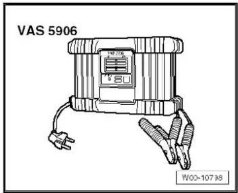
Overview of operating panel:
1 - Charge condition display 25 %.
2 - Charge condition display 50 %.
3 - Charge condition display 75 %.
4 - Charge condition display 100 %.
5 - Display ready
6 - Start/stop and Setup buttons for interrupting and resuming charging process. Entry to Setup menu and selection of characteristic type (press for 10 s).
7 - Malfunction display.
- Place charger in engine compartment or under vehicle.
- Connect mains cable to charger and plug it into mains.
Charger is in no-load operation - ready light is on.

WARNING
Danger of injury! Observe warning notices and safety regulations ⇒ page 2!
- Switch off ignition.
- Connect red charging cable to positive terminal „+“ on battery.

Note
In vehicles with start/stop function and battery monitor control unit -J367- fitted, black terminal clamp must be connected to body earth. Connecting it to battery negative terminal will cause start/stop system to malfunction.
- Connect black charging cable to negative terminal „-“ on battery.
Charging starts after about 2 seconds.
Number of LEDs lit indicates charge condition of battery. Battery has been charged up once all lights are lit.
When battery is fully charged, battery charger -VAS 5906- automatically switches over to trickle charging.

Caution
Danger of sparking if charging terminals are removed too soon. Terminate charging by pressing start/stop button.
- Press start/stop button to terminate charging.
- Disconnect black charging cable from negative terminal „-“ on battery.
- Disconnect red charging cable from positive terminal „+“ on battery.
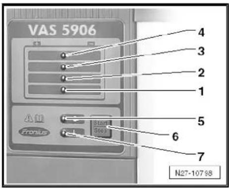

3.5 Midtronics - INC 940- battery charger only for USA/Canada
Warning and safety regulations page 2
General description page 55
Charge battery page 56.
Dealing with problems with Midtronics -INC 940- battery tester page 58
3.5.1 General description of Midtronics -INC 940- battery tester
Batteries in VW vehicles are only allowed to be charged with battery chargers approved by VW. In the USA/Canada, it is permitted for the Midtronics INC 940- battery charger to be used.
Midtronics -INC 940- battery charger combines battery charging with a charge condition checks and a battery test.
The following charging and analysis procedures apply to all batteries, all battery installation locations (engine compartment or luggage compartment) and battery application purposes (starter battery or second/convenience battery).
Always comply with the safety regulations, the regulations for setting up the battery charger, the display menu/display buttons, LEDs and the operating procedures described in the operating manual INC 940.
Read through operating manual INC 940 carefully.
Refer to Self-study programme No. ; Vehicle batteries for more information.

WARNING

Danger of injury! Observe warning notices and safety regulations page 2!
No naked flames, sparking or smoking in the vicinity of batteries.
Battery charger must be switched off before cables are connected or disconnected.
Do not remove cell plugs during charging.
Overcharging sulphated batteries can lead to explosions.
Do not store precision tools in rooms where batteries are charged, because corrosion can ensue due to chemical reactions.

WARNING
Batteries where the magic eye is colourless or light yellow must not be checked or charged. Do not slave/jump start the vehicle!
Danger of explosion when checking and charging or slave/jump starting
These batteries must be renewed.
3.5.2 Charging battery
Prerequisites:

WARNING
Batteries where the magic eye is colourless or light yellow must not be checked or charged. Do not slave/jump start the vehicle!
Danger of explosion when checking and charging or slave/jump starting
These batteries must be renewed.
INC 940 initial setup performed (dealership number, date/time) ⇒ operating manual INC 940.
- Check general information page 55.
- Open bonnet or cover for other installation location of battery.
- Perform visual check of battery page 6.
- Determine whether battery type is „Standard“ (wet battery) or „AGM“ (absorbent glass mat battery).
- Close all vehicle doors.

Note
◆ Battery temperature must be at least 10 °C.
For additional information, refer to the operating manual INC 940.
Perform charging procedure:
- Switch off all electrical consumers.
- Switch off ignition and remove ignition key.
- Connect red terminal clamp „+“ of charger unit to positive terminal on battery.

Note
In vehicles with start/stop function and battery monitor control unit -J367- fitted, black terminal clamp must be connected to body earth. Connecting it to battery negative terminal will cause start/stop system to malfunction.
- Connect black terminal clamp, "of battery charger to negative terminal.
- Connect Midtronics -INC 940- battery charger to an earthed socket.
- Set „ON/OFF“ switch of Midtronics -INC 940- battery charger to „ON“.
- Select „Automatic“ or „Manual“ charging mode.
- Select test „In vehicle“ or „Outside vehicle“.
- Select battery type „Standard“ or „AGM“ (absorbent glass mat).
- Select test type „Warranty“ or „Miscellaneous“. Note additional details (depending on type of test).

Note
For additional information, refer to the operating manual INC 940.
If necessary, make a note of menu items required for „Warranty“ test type ⇒ Warranty service circular.
Midtronics -INC 940- battery charger tests battery and starts charging procedure. Display then shows one of three results, as well as approximate charging time.
| Result: | Measures: |
| Battery OK | Battery can be returned to operation. |
| Charging required | ◆ Test found low charge level.◆ Charging starts and approximate charging duration is displayed.◆ Achieved cold-start performance and remaining charging time are displayed, and are updated regularly. |
| Renew battery. | Battery defective. Charging procedure is interrupted. Renew battery. |

Note
In case Midtronics -INC 940- shows fault messages or text displays other than those listed above, please refer to → page 58.

WARNING
Stop charging if battery is liberating a lot of gas. Press „Stop" button on front.
When charging and testing procedure has finished, Midtronics - INC 940- battery charger displays „Battery good“ or „Renew battery“ and total charging time.
There are three possible messages depending on individual circumstance (printout for warranty, repair job, evaluation and filing):
◆ Generate test code (only possible after automatic charging and test).
◆ Print last test result (for warranty).
◆ Display last test results.


Note
For additional information, refer to the operating manual INC 940.
3.5.3 Dealing with problems with Midtronics - INC 940- battery tester
Under certain circumstances, the display may show errors or messages according to status.
The most frequent display messages are listed below, together with suggested solutions.

Note
For messages not listed here, please refer to operating manual INC 940.
| Display message | Measures |
| Check connection. | - Check whether terminals of battery charger are firmly connected to battery terminals.- Check battery terminals are tightened according to regulations and do not have corrosion. |
| Terminals connected? | Safety function of tester.- Connect terminals to battery before starting charging procedure. |
| System noise | - Switch off all electrical consumers.- Wait until all electrical loads monitored by onboard supply control unit have switched off.- Remove ignition key.- Disconnect any suspect electrical equipment not connected to onboard supply as standard. |
Wait a few minutes and repeat charging procedure page 56.
3.6 Solar panel -VAS 6102A-
3.6.1 Charging battery in maintenance mode with solar panel -VAS 6102A-
Solar panel VAS 6102A
General description:
Solar panel -VAS 6102A- supports onboard supply and prevents spontaneous battery discharging.
Solar panel -VAS 6102A- achieves max. voltage of 14.3 V and a charging current of max. 255 mA.
Solar panel -VAS 6102A- is allowed to be used for charging all rechargeable lead or lead gel batteries.
Solar panel -VAS 6102A- is connected to diagnostic connection in vehicle.
A green LED is integrated in the frame to indicate its function. The brighter the LED, the higher the charging current.
Integrated electronics prevent battery overcharging.
- Secure solar panel -VAS 6102A- on interior mirror -1-.
- Place underside on dash panel -2-.

Note
Solar panel -VAS 6102A- is not allowed to lie fully on dash panel. It is only allowed to be positioned with the bottom edge for support. Placing it fully on the surface can result in discolouration of the dash panel.
- Pull attachment string tight so that solar panel -VAS 6102A- is positioned close to windscreen.
- Connect solar panel -VAS 6102A- to diagnostic connection of vehicle. Connection procedure is as for vehicle diagnostic tester page 78
- Check function of solar panel -VAS 6102A-. Green LED indicates function of solar panel -VAS 6102A-.
3.7 Totally discharged batteries

WARNING
Danger of injury! Observe warning notices and safety regulations ⇒ page 2 !
A battery is designated „totally discharged“ when the no-load voltage is less than 11.6 V.
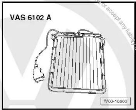
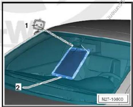

WARNING
Batteries where the magic eye is colourless or light yellow must not be checked or charged. Do not slave/jump start the vehicle!
Danger of explosion when checking and charging or slave/jump starting
These batteries must be renewed.

Caution
- Totally discharged batteries freeze prematurely.
◆ Frozen batteries should no longer be used.

Note
Totally discharged batteries in vehicles before registration must be exchanged prior to delivery. Preliminary damage cannot be excluded.
◆ Batteries that have not been used for a long period of time discharge themselves, e.g. those fitted in stored vehicles.
In totally discharged batteries, the electrolyte is comprised almost entirely of water because the acid content is so low.
Totally discharged batteries sulphate, that means, the entire plate surfaces of the battery harden.
If a battery is recharged shortly after it has totally lost its charge, the sulphation will mostly dissipate.
If these batteries are not recharged, the plates continue to harden and the ability to recharge is reduced. The result of which is a reduction in the battery output.
Check battery no-load voltage page 25.

4 Cruise control system (CCS)
General description:
The functions of the cruise control system are controlled by the engine control unit.
- The cruise control system can be activated/deactivated page 61.
Fault detection and fault display
Faults on the CCS are output via the engine control unit.
For fault finding, use vehicle diagnosis, testing and information system in „Guided fault finding“ mode.
4.1 Activating and deactivating cruise control system (CCS)
- Connect vehicle diagnostic tester page 78.
- Select „Guided fault finding“ mode in vehicle diagnostic tester.
- Using „GoTo“ button, select „Functions/component“ and the following menu options in succession:
Drive
◆ Engine code
◆ 01 - On Board Diagnostic capable systems
◆ Engine management/diesel direct injection and glow plug system
◆ Functions
◆ Activating and deactivating cruise control system (CCS)
90 – Gauges, instruments

92 – Windscreen wash/wipe system
1 Washer fluid line hose couplings
The following hose coupling types are used to connect the hoses to pumps and spray jets and/or as points of separation:
1.1 Windscreen and rear window washer system
- Pull the two coupling sections apart (no securing device) to loosen the connection.
- To secure the connection, push the two coupling sections together, until you hear and feel them engage.
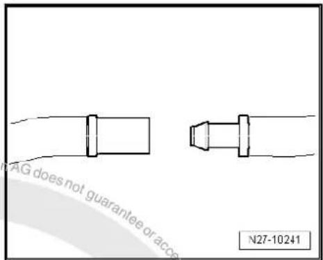
- To loosen the connection, rotate the lock ring -1- through 90° -arrow- and pull off the hose connection.
- To secure the connection, push on the hose connection and rotate the lock ring -1--arrow- until it engages.
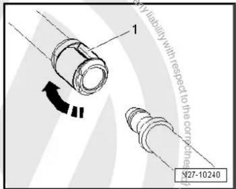
- To loosen the connection, pull up the lock ring -1- by approx. 1 mm -arrow- and pull off the hose connection.
- To secure connection, attach hose connection and press in clip -1- until it engages.
- To secure connection, attach hose connection and press in clip -1- until it engages.
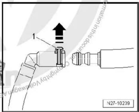
- To loosen the connection, pull up the lock ring -1--arrow- and pull off the hose connection.
- To secure connection, attach hose connection and press in clip -1- until it engages.
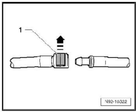
1.2 Headlight washer system
- To loosen the connection, push the lock ring -1- -arrow- and pull off the hose connection.
- To secure the connection, push and hold the lock ring -arrow- and push on the hose connection. Check that the securing clip has correctly engaged by depressing and trying to pull off without the clip.
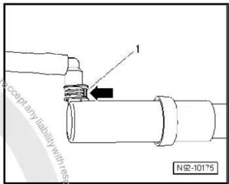
2 Hose repair
A new repair concept has been developed for repairs to washer system hoses. Various connectors, special EPDM hoses (ethylene-propylene terpolymer) and heat-shrink hose are available as spare parts.
2.1 General description
◆ The replacement parts can be found in the electronic parts catalogue (ETKA).
◆ Replacement parts are available for repair of both smooth and corrugated pipes.
2.2 Repairing smooth pipe
Smooth pipe with a diameter or 5x1 mm or 6x1 mm can be repaired with EPDM hose.
- Cut damaged section at right angles out of smooth pipe which is to be repaired.
- Select the appropriate EPDM hose -2- and cable ties according to the electronic parts catalogue (ETKA).
- Cut EPDM hose -2- so that ends -1- and -3- of smooth pipe can each be pushed about 10 mm into the EPDM hose -2-.
- Secure the repair joints with cable ties -1-.
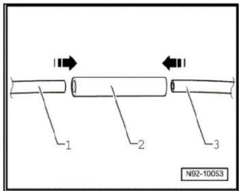
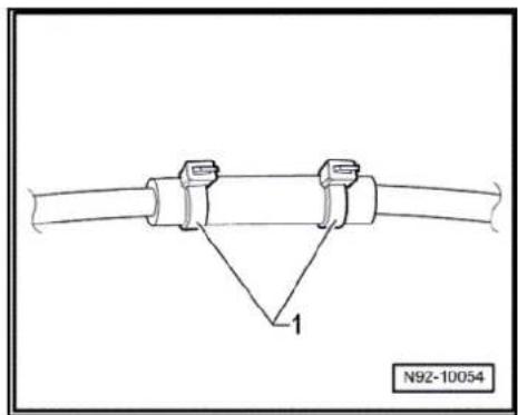
2.3 Repairing corrugated pipe
Special tools and workshop equipment required
◆ Hot air blower -VAS 5179- or
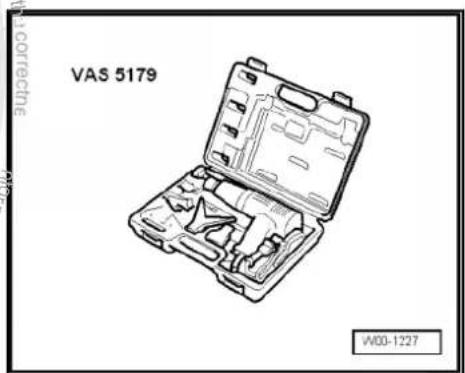
◆ Hot air blower -V.A.G 1416/- or
◆ Hot air blower -VAS 1978/14-


Note
◆ Repair points must not be subjected to pulling or bending forces.
If the damaged section is longer than 20 mm, a new piece of corrugated pipe must be used and the procedure described below must be performed twice.
- Cut damaged section at right angles out of corrugated pipe which is to be repaired.
- Select suitable end pieces -2- and -3- and correct sized shrink-fit piping from the electronic parts catalogue (ETKA).
- Heat end of corrugated pipe -1-.
- Push connector -2- into corrugated pipe -2- -arrow A-.
- Heat end of corrugated pipe -4-.
- Push connector -3- into corrugated pipe -4- -arrow B-.
- Cut heat-shrink hose so that ends of corrugated pipe are each covered by about 20 mm -dimension x- of heat-shrink hose.
- Push heat-shrink hose over corrugated pipe, join connectors and secure repair joints with heat-shrink hose.
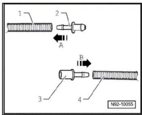
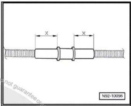
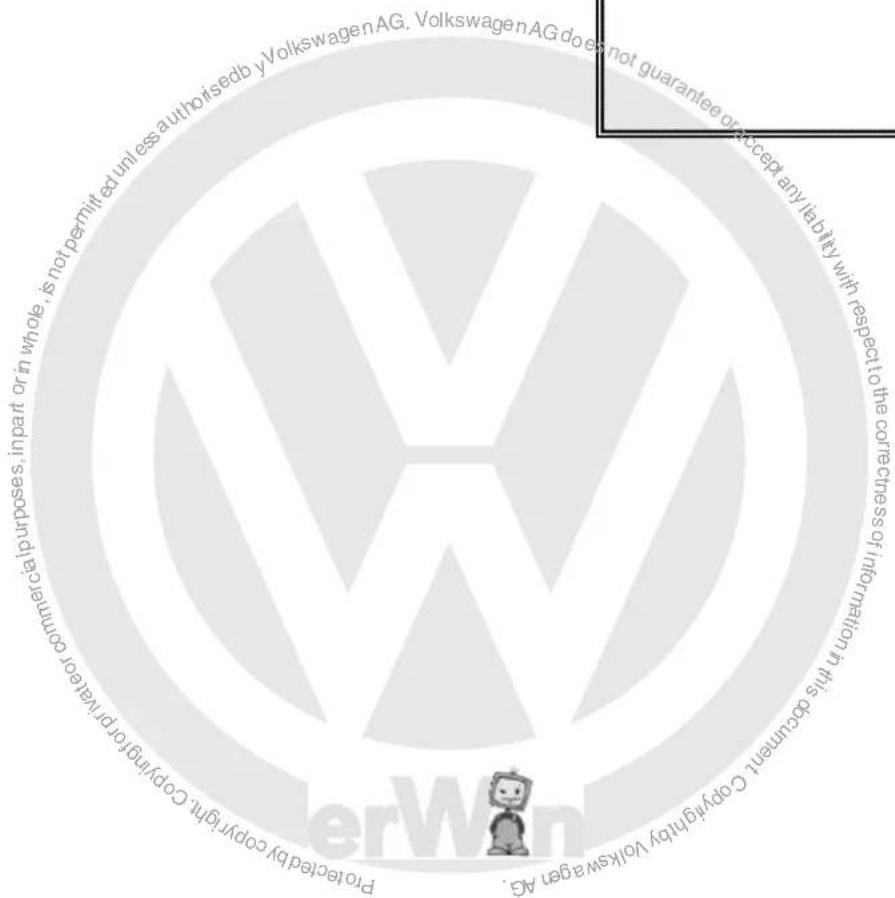
3 Distinguishing features of jointless wiper blades
Distinguishing features from Bosch and Federal Mogul.
When renewing wiper rubbers, note the make. When renewing wiper blades, the same make must be used.
Wiper blades can be identified according to wiper arm fastening.
Bosch wiper blades -1 and 2-:
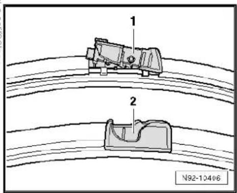
Federal Mogul wiper blades -1-:

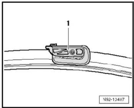
natural_image
Technical line drawing of a mechanical component with labeled part '1' and reference number N92-10407 (no text or symbols on the diagram itself)94 – Lights, bulbs, switches - exterior
1 Operation and safety notes for gas discharge bulbs
- If repairs are to be made to the headlight with gas discharge bulbs, observe the following:
Notes on dangerous high voltage/currents → page 68
Notes on pressure, temperature, radiation/arcs → page 69
◆ Assembly notes for gas discharge bulbs ⇒ page 70
◆ Disposal regulations for gas discharge bulbs → page 70
Special tools and workshop equipment required
◆ Protective goggles
Gloves

WARNING
It is absolutely necessary to disconnect the battery earth strap before working on parts of the gas discharge headlights marked with yellow high voltage symbols.
Then switch dipped beam on and off again. This will eliminate any possible residual voltage.
The gas discharge lamp control unit must never be operated without a gas discharge lamp.
Due to the high voltage (above 28000 V when igniting the gas discharge bulb) and temperatures, the gas discharge bulb must only be operated in the headlight housing.


WARNING
◆ Never change bulbs if you are not familiar with the appropriate procedures, safety precautions and tools.
Notes on dangerous high voltage and current

WARNING
Control units for light systems, connectors and components pertaining to bulb holders conduct lethally high voltage.
Operating the control unit and the starter unit is permitted only with the bulb fitted.

WARNING
- Switch off ignition and all electrical consumers and remove ignition key.
When working on headlight system, ensure that there is no voltage in any components, including the dissipation of residual voltage after the headlights are switched off.
Residual voltage can be dissipated by turning the dipped beams on and then off again after withdrawing the ignition key.
When working on the headlight system, ensure that the lights cannot be switched on.
Notes on pressure, temperature, radiation/arcs

WARNING
- The bulbs may be operated in the headlight housing only (protection against contact due to very hot bulbs, absorption of UV radiation, avoidance of dazzling light, protection against explosion).
• The glass of the bulbs can be very hot - danger of burns. - Avoid looking directly into the beam, as the UV rays from the gas discharge bulb are about 2.5 times greater than normal halogen bulbs.
- Avoid looking into the light beam (danger of glare); vision may be impaired for a substantial time.

WARNING
- Avoid contact with burst bulbs.
- H7 bulbs and gas discharge bulbs (xenon and bi-xenon) are under pressure and can explode while being changed - danger of injury.
• Always wear protective goggles and gloves when removing and installing gas discharge bulbs.
Repair notes for gas discharge bulbs

Caution
Before exchanging a bulb, always switch off the affected consumers.
◆ Switch off ignition and all electrical consumers and remove ignition key.
Do not touch the bulb glass with bare fingers; use clean cloth gloves. When the light bulb is switched on, the heat would vaporise the oil of the finger prints which would then settle on the reflector, impairing the brightness of the headlight.
A light bulb must always be renewed with a bulb of the same sort. The designation appears on the base of the bulb or on the bulb glass.
◆ Properly engage connectors during installation and ensure tight seating of the connection.
Disposal regulations for gas discharge bulbs

WARNING
- Gas discharge bulbs must be disposed of as hazardous waste; never dispose of gas discharge bulbs as conventional waste.
- Gas discharge bulbs contain metallic mercury (Hg) and traces of thallium; never destroy these bulbs.
• These components must be recycled in accordance with national law. - Dispose of only in containers intended for this purpose at an authorised collection point.
96 – Lights, bulbs, switches - interior
1 12 V socket
1.1 Removing and installing 12 V socket

Caution
If excessive force is exerted on sockets without illumination, the retaining sleeve may be damaged.
Only illuminated sockets (cigarette lighter) can be removed with the puller T 40148.
The puller does not manage to release the locking lugs of sockets without illuminated retaining sleeve.
Usually sockets without illumination cannot be removed without being damaged.
Refer to removing and installing cigarette lighter -U14 ⇒ page 72.
1.2 Removing and installing socket illumination bulb -L42-
The removal of the socket illumination bulb -L42- is performed in the same way as the removal of the cigarette lighter illumination bulb -L28- page 76.

2 Cigarette lighter -U1-
The following descriptions apply to the rear left cigarette lighter -U3-, rear right cigarette lighter -U7-, rear cigarette lighter -U9-, 12 V socket 2 -U18-, 12 V socket 3 -U19-, 12 V socket 4 -U20-, cigarette lighter 2 -U25- and 12 V socket 5 -U26- so far as they are illuminated.

Caution
If excessive force is exerted on sockets without illumination, the retaining sleeve may be damaged.
Only illuminated sockets (cigarette lighter) can be removed with the puller T 40148.
The puller does not manage to release the locking lugs of sockets without illuminated retaining sleeve.
Usually sockets without illumination cannot be removed without being damaged.
2.1 General description

Caution
If excessive force is exerted on sockets without illumination, the retaining sleeve may be damaged.
Only illuminated sockets (cigarette lighter) can be removed with the puller T 40148.
The puller does not manage to release the locking lugs of sockets without illuminated retaining sleeve.
Usually sockets without illumination cannot be removed without being damaged.
On some vehicles, the illumination is not provided by a light bulb, but by an LED (light-emitting diode), depending on the equipment level. This LED is permanently attached to the retaining sleeve and cannot be renewed separately.
Retaining sleeves with a light bulb are available in different versions. On the one version, the light bulb can be replaced separately; on the other version, the light bulb cannot be replaced separately. In this case, the bulb carrier has to be replaced together with the light bulb.
Depending on the space requirement, the vehicles are equipped with various electric sockets and cigarette lighter sockets. They differ in length and have different electrical connections. In the case of electric sockets or cigarette lighter sockets with a wiring tail, it may be necessary to perform additional work in order to gain access to the connector.
2.2 Assembly overview

Caution
If excessive force is exerted on sockets without illumination, the retaining sleeve may be damaged.
Only illuminated sockets (cigarette lighter) can be removed with the puller T 40148.
The puller does not manage to release the locking lugs of sockets without illuminated retaining sleeve.
Usually sockets without illumination cannot be removed without being damaged.
1- Cigarette lighter socket with wiring tail
2- Cigarette lighter
3 - Socket
4- Cigarette lighter socket
5 Retaining sleeve
6 - Light bulb W 5 12 V 1.2 watt
7 - Bulb carrier
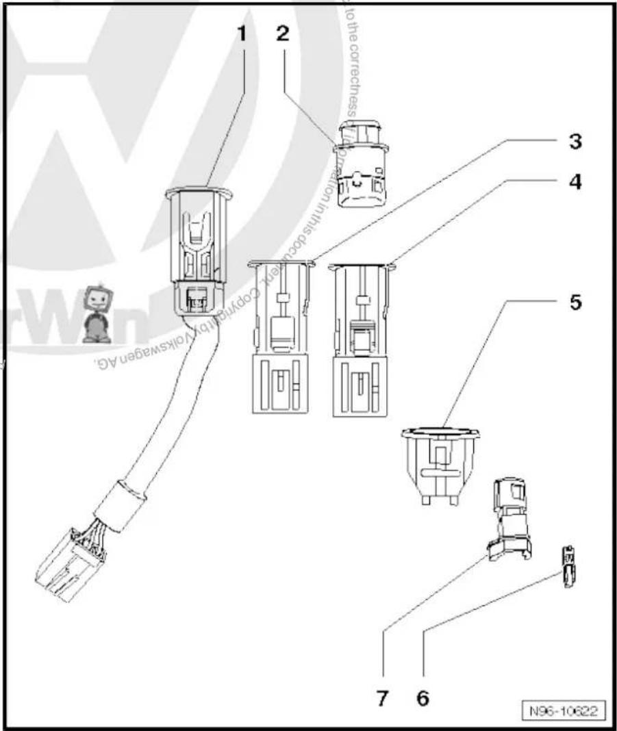
2.3 Removing and installing cigarette lighter socket

Note
The removal and installation procedure is the same for all sockets and is therefore described here only for the cigarette lighter socket.

Caution
If excessive force is exerted on sockets without illumination, the retaining sleeve may be damaged.
Only illuminated sockets (cigarette lighter) can be removed with the puller T 40148.
The puller does not manage to release the locking lugs of sockets without illuminated retaining sleeve.
Usually sockets without illumination cannot be removed without being damaged.
Special tools and workshop equipment required
◆ Puller -T 40148-
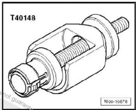
natural_image
Technical line drawing of a mechanical component labeled T40148, showing threaded and flanged parts (no text or symbols beyond labels)Removing
- Remove cigarette lighter, dummy cigarette lighter etc. from socket if necessary.

Note
For reasons of clarity, the socket is removed in the illustration.

Caution
The socket or the retaining sleeve can be damaged.
Ensure that the puller is seated correctly, otherwise the retaining lugs of the retaining sleeve will not be released.
- Push puller -arrow- into socket so that locking lugs -1- engage in recesses -2-.
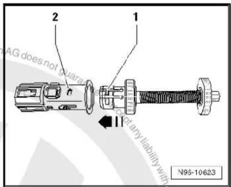
- Pull grip -3- in direction of -arrow- to release locking lugs of retaining sleeve.
- Pull socket out of retaining sleeve using puller.

Caution
The socket wiring can be damaged.
Take care not to stretch the wiring when pulling out the socket.
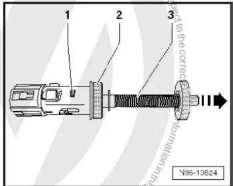
Depending on the fitting location, it is recommended to use the thrust piece 40148/1 -2- with the knurled nut -1-.

Caution
When using the thrust piece, ensure that no surrounding components are damaged.
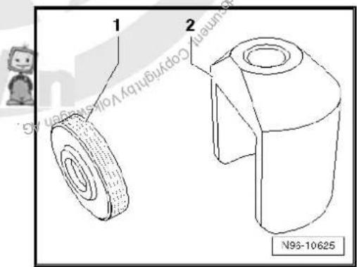
– Pull off socket connector.

Note
Depending on the space requirement, the vehicles are equipped with various electric sockets and cigarette lighter sockets. They differ in length and have different electrical connections. In the case of electric sockets or cigarette lighter sockets with a wiring tail, it may be necessary to perform additional work in order to gain access to the connector.
- Release puller locking lugs by pressing spindle -1- in direction of -arrow B-. Then release puller -2- by turning it briefly to left -arrow A-. Remove puller from socket.

Note
Ensure that the puller locking lugs are not spread.

Caution
The cigarette lighter might be ejected out of the socket after the heating phase.
When the puller is mounted, the socket retaining springs are pressed apart and the retaining force is reduced.
After removing the socket, carefully press the retaining springs together and check if the cigarette lighter remains in the removal position after the heating phase.
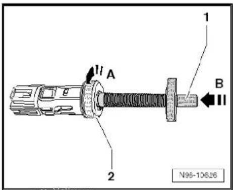
- Carefully press socket retaining springs together -arrows-.
- Check if cigarette lighter remains in removal position after heating phase and ensure it is not ejected in vehicle interior.
Installing
Install in reverse order of removal.
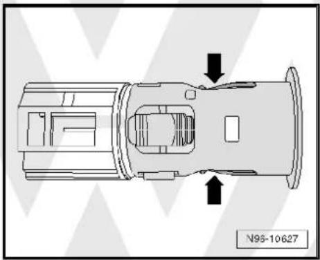
natural_image
Top-down schematic of a vehicle or mechanical component with directional arrows indicating movement or flow (no text or symbols present)2.4 Removing and installing cigarette lighter illumination bulb -L28-

Note
On some vehicles, the illumination is not provided by a light bulb, but by an LED (light-emitting diode), depending on the equipment level. This LED is permanently attached to the retaining sleeve and cannot be renewed separately.
◆ Retaining sleeves with a light bulb are available in different versions. On the one version, the light bulb can be replaced separately; on the other version, the light bulb cannot be replaced separately. In this case, the bulb carrier has to be replaced together with the light bulb.
Removing:
- Remove socket page 74.
- Press retaining lugs -arrows- and remove retaining sleeve together with bulb carrier.
– Unclip bulb carrier from retaining sleeve.
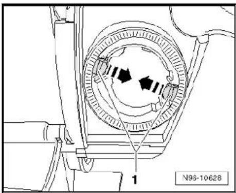
natural_image
Technical diagram of a mechanical assembly with concentric rings and directional arrows, no readable text or symbols- Separate bulb carrier in areas -A- and -B-.
- Open part -B- of bulb carrier.
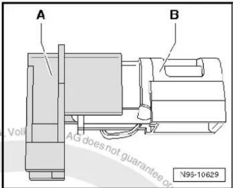
- Remove light bulb in direction of -arrow-
Installing:
Installation is carried out in reverse order of removal.
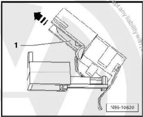

97 – Wiring
1 Vehicle diagnostic, testing and information systems

WARNING
During testing or measuring operations using a vehicle diagnostic information system, there is a risk of serious or even fatal injury!
If the vehicle diagnostic information system is lodged in the activity area of an airbag during a testing or measuring operation, a triggered airbag can result in serious or even fatal injury!
During testing and measuring operations, work with a person who can operate the vehicle diagnostic and information system from one of the back seats.

Note
All the operations described, e.g. adaptation, coding, etc. can be performed using the vehicle diagnostic tester.
All work procedures can be found in „guided fault finding“ and „guided functions“ modes.
◆ Additional information
→ Self-study programme No. 202 ; Vehicle diagnostic, testing and information system VAS 5051
→Self-study programme No. 256 ; VAS 5052
⇒ Self-study programme No. 294 ; Online connection of VAS 5051
- Connecting vehicle diagnostic tester page 78
1.1 Connecting vehicle diagnostic tester

Note
Observe the latest operating instructions for vehicle diagnostic tester, which are displayed after selecting the „Administration“ and „Operating Manual“ keys.
Special tools and workshop equipment required
◆ Vehicle diagnostic tester
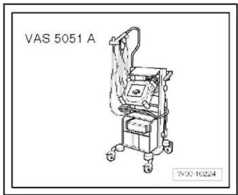
◆ Diagnostic cable -VAS 5051/6A- (5 m)
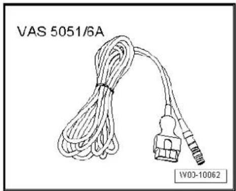
natural_image
Line drawing of a cable with connectors and a connector, labeled VAS 5051/6A and W03-10062 (no text on the cable itself)◆ Diagnostic cable -VAS 5051/5A- (3 m)

Note
Only these cables are to be used for diagnosis, as they are the only ones fitted with CAN wiring and therefore allowing CAN diagnosis and/or CAN communication.
Connecting vehicle diagnostic tester :
- Apply handbrake.
- Vehicles with automatic gearbox, move selector lever to position „P“ or „N“.
- Vehicles with manual gearbox, move gearstick to neutral position.
- With ignition switched off, connect vehicle diagnostic tester using diagnostic cable -VAS 5051/6A- to diagnostic interface -arrow- in vehicle.
- Switch on ignition.
- Switch off all electrical consumers.

Note
All other and the following vehicle diagnostic, testing and information systems or vehicle diagnostic and service information systems are connected accordingly in the sequence described above.
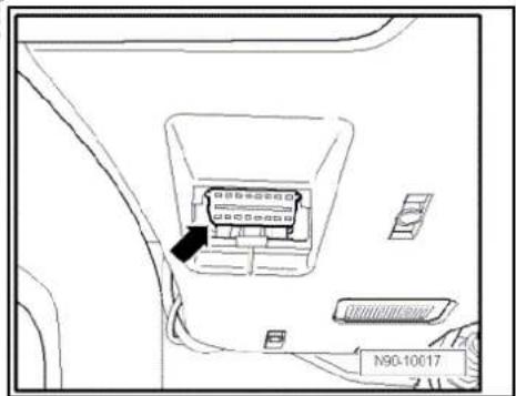
1.2 Connecting vehicle diagnostic tester Golf Model Year 1998 - 2003
- Apply handbrake.
- Vehicles with automatic gearbox, move selector lever to position „P“ or „N“.
- Vehicles with manual gearbox, move gear lever to neutral position.
– Pull out trim -1- in direction of arrow. - With ignition switched off, connect vehicle diagnostic tester using diagnostic cable to diagnostic interface -arrow- in vehicle.
- Switch on ignition.
- Switch off all electrical consumers.

Note
All other and the following vehicle diagnosis, testing and information systems or vehicle diagnostic and service information systems are connected accordingly in the sequence described above.
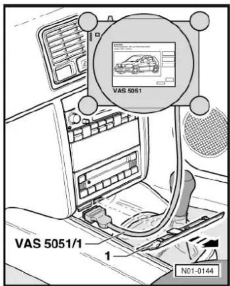

2 Repairing wiring harnesses and connectors
2.1 Wiring harness repair set
2.1.1 Wiring harness repair set -VAS 1978-
Wiring harness repair set -VAS 1978- allows optimal repair quality to be achieved in the area of vehicle electrics. Using the tools, repairs to connectors and wiring open circuits can be carried out. To do this, complete repair wire sections with contacts already crimped on are used and joined to the vehicle's own wiring harness with the aid of crimp connectors. A special set of pliers with three different crimp recesses and a hot air blower for shrinking the crimp connectors make a perfect electrical connection.

Note
Additional information:
⇒ Operating instructions Wiring harness repair set -VAS 1978-
2.1.2 Upgrade kit -VAS 1978/50-
Upgrade kit -VAS 1978/50- is required to bring the „old“ wiring harness repair set -VAS 1978- up to the latest standard of wiring harness repair set -VAS 1978A-. The upgrade kit comprises of 4 assembly and 10 release tools, a new set of crimping pliers for crimp connectors with head adapter 0.35 - 2.5 mm ^2 -VAS 1978/1-1-, 4.0 - 6.0 mm ^2 -VAS 1978/2 A- and head adapter for JPT contacts -VAS 1978/9-1-. Also included are new stickers, a new set of operating instructions, crimp connectors for 0.35 mm ^2 cable cross-section and a roll of black felt adhesive tape.

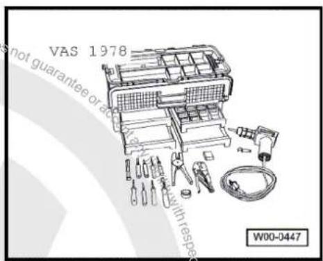
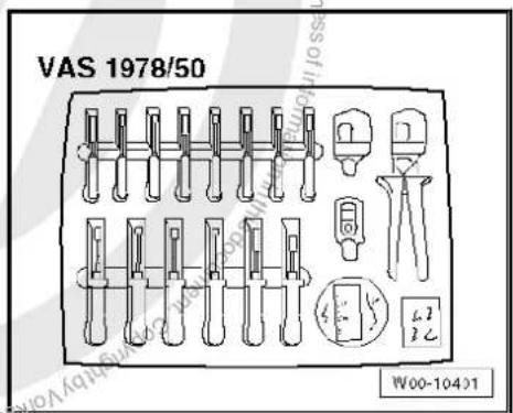
2.1.3 Wiring harness repair set -VAS 1978A-
The new wiring harness repair set -VAS 1978A- allows optimal repair quality to be achieved in the area of vehicle electrics. Using the new pliers, repairs to connectors and wiring open circuits can be carried out. To do this, complete repair wire sections with contacts already crimped on are used and joined to the vehicle's own wiring harness with the aid of four different types of crimp connectors. A new set of crimping pliers with head adapters and a hot air blower for shrinking the crimp connectors make a perfect electrical connection.

Note
Additional information:
⇒ Operating instructions Wiring harness repair set -VAS 1978A-
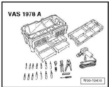
2.1.4 Release tool set -VAS 1978/35-
Release tool set -VAS 1978/35- serves as a means of releasing various primary and secondary locking devices in Group vehicles. The set comprises of 26 different tools with which, for example, round connector systems, flat contacts with one or two fasteners and also single wire seals can be released or fitted.
Allocation of the correct release tool to the respective locking devices can be gleaned from the table in the operating instructions of -VAS 1978/35-.
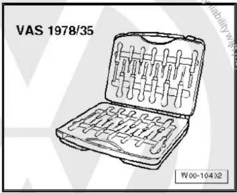
2.2 Tool descriptions
2.2.1 Special pliers with insert
The special pliers without insert -VAS 1978/1- with insert for special pliers -VAS 1978/2- is part of the wiring harness repair set -VAS 1978- and is used to crimp connectors during wiring harness repairs.
| Colour of crimp connector | Colour of crimp recess | Wiring cross section |
| Yellow | Yellow. | 0.35 mm^2 |
| Red | Red. | 0.5 mm^2 - 1.0 mm^2 |
| Blue | Blue | 1.5 mm^2 - 2.5 mm^2 |
| Yellow. | Yellow. | 4.0 mm^2 - 6.0 mm^2 |
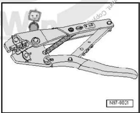
natural_image
Technical line drawing of a wire crimping tool (no text or symbols on the diagram itself)
Note
As an alternative, the connectors can also be crimped with crimping pliers (base tool) -VAS 1978/1-2- in conjunction with head adapters -VAS 1978/1-1- or -VAS 1978/2A->page 84.
◆ Ensure without fail that the correct crimp recess is chosen for the crimp connectors being used.
◆ The insulation on the wires must not be crimped.
2.2.2 Release tools for contacts
The various release tools serve as a means of detaching the different contacts from the contact housings without damage.
A selection of release tools is included in wiring harness repair set -VAS 1978- and wiring harness repair set -VAS 1978A-. The complete set of release tools is included in release tool set -VAS 1978/35- page 82.

WARNING
Some tools are equipped with a tool safety device. This must be pushed over the tip of the tool after use in order to protect the tip and prevent personal injury.
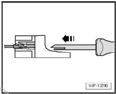
Releasing and dismantling contact housings page 102.
2.2.3 Assembly tools for single wire seals
The assembly tools serve as a means of sliding the single wire seals fully into the contact housing without damage and thereby assure complete sealing between single wire and contact housing.
Four assembly tools for single wire seals are included in each wiring harness repair set -VAS 1978 B- and previous versions.
Assembling single wire seals page 99.
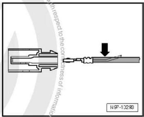
2.2.4 Wire strippers -VAS 1978/3-
Wire strippers -VAS 1978/3- serve as a means of stripping insulation off wires and cutting wires in the correct manner.
Wire strippers -VAS 1978/3- are included in wiring harness repair set -VAS 1978 B- and previous versions.
The wire strippers have an adjustable limit stop within the pliers jaws, with which the desired length of insulation to be removed can be adjusted.
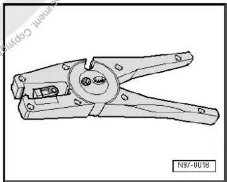
natural_image
Technical line drawing of a wire crimping tool (no text or symbols on the diagram itself)Stripping:
- Adjust the sliding limit stop in the pliers jaws to the desired length of insulation to be removed.
- Insert the end of the wire from the front fully into the pliers jaws and squeeze the pliers together completely.
- Open the pliers and removed the stripped wire end.
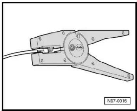
natural_image
Technical line drawing of a mechanical clamp or crimping tool with no visible text or symbols- Cut the wire if necessary with the cutting part on the upper side of the wire strippers.
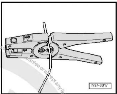
2.2.5 Hot air blower, 220 V / 50 Hz -VAS 1978/14-

Caution
When shrink-fitting, take care not to damage any other wiring, plastic parts or insulating material with the hot air blower.
Observe the operating instructions of the hot air blower without fail!
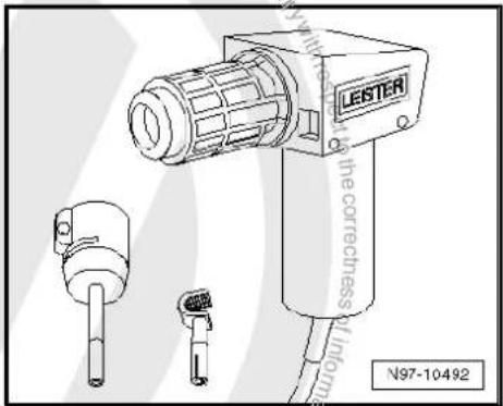
natural_image
Technical line drawing of a LESTER electric shaver with two small components (no text or symbols)The hot air blower, 220 V / 50 Hz -VAS 1978/14- is used in conjunction with shrink element for hot air blower -VAS 1978/15- to shrink fit the crimp connectors. After crimping, the crimp connector has to be shrink fitted using the hot air blower in order to prevent any ingress of moisture.
Hot air blower, 220 V/50 Hz -VAS 1978/14- is included in wiring harness repair set -VAS 1978 B- and previous versions.
Shrink fitting crimp connectors using hot air blower, 220 V / 50 Hz -VAS 1978/14- ⇒ page 94 , or ⇒ page 96 .
2.2.6 Crimping pliers -VAS 1978/1A-
Crimping pliers -VAS 1978/1A- or crimping pliers (base tool) -VAS 1978/1-2- together with head adapter 0.35 - 2.5 mm ^2 -VAS 1978/1-1- or head adapter 4.0 - 6.0 mm ^2 -VAS 1978/2A- are used to squeeze together crimp connectors from the wiring harness repair sets.
Crimping connectors using crimping pliers -VAS 1978/1A- page 96.
The following heads adapters are available for crimping pliers (base tool) -VAS 1978/1-2- :
◆ Head adapter 0.35 mm² - 2.5 mm² - VAS 1978/1-1-
◆ Head adapter 4.0 mm² - 6.0 mm² - VAS 1978/2A-
◆ Head adapter for JPT contacts -VAS 1978/9-1-
In conjunction with head adapter for JPT contacts -VAS 1978/9-1-, the crimping pliers are used to crimp contacts to single wires during repairs to wiring with cross sections up to 0.35 mm ^2 ⇒ page 91 .
Interchanging head adapter:
- Open up the crimping pliers fully.
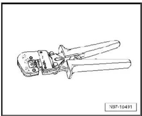
natural_image
Line drawing of a wire crimping tool (no text or symbols on the diagram itself)- Unclip both locking pins -arrows- from the body of the crimping pliers.
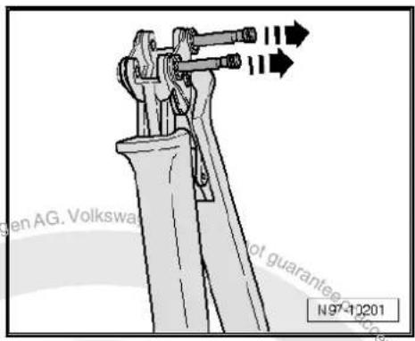
- Insert the required head adapter from above -arrow- in the body of the crimping pliers.
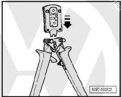
natural_image
Mechanical assembly diagram showing a clamp or tool inserted into a component, with no visible text or symbols.- Lock the head adapter by engaging the pins -arrows- in the body of the crimping pliers.
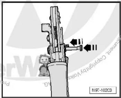
2.3 General notes concerning repairs to vehicle electrical system

Caution
When batteries are disconnected and reconnected, the procedure described in the workshop manual must be strictly observed.

WARNING
Some tools are equipped with a tool safety device. This must be pushed over the tip of the tool after use in order to protect the tip and prevent personal injury.
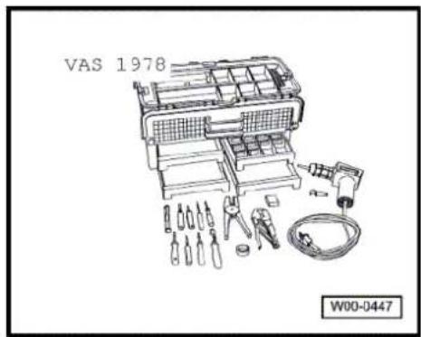
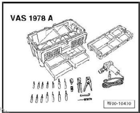
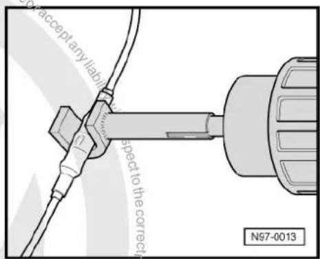
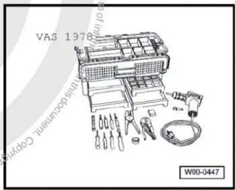

◆ Observe the latest notes in the respective workshop manual when carrying out repairs.
◆ Observe country-specific regulations.
◆ Always disconnect the battery earth strap before working on the electrical system. Disconnecting the battery earth strap (open circuit) provides a safe working environment for repairs to the electrical system. The battery positive wire need only be disconnected for removal of the battery.
Before starting a repair, it is important to identify and rectify the cause of damage (e.g. sharp edges on body panels, defective electrical components, corrosion, etc.).
For additional information, e.g. removal and installation of individual components, please refer to the relevant workshop manual.
◆ Soldering is not permitted for repairs to vehicle wiring.
◆ Wiring harness and connector repairs to vehicle electrical system should be carried out using wiring harness repair set -VAS 1978 B- and previous versions only. Only use yellow wires from wiring harness repair set -VAS 1978 B-.
◆ Wiring harness repairs may not be integrated in the vehicle's own wiring harness and must be marked with the use of yellow adhesive tape. This indicates a previous repair.
◆ Crimp connectors may never be repaired. If necessary, lay wiring parallel to the defective wiring. After crimping, crimp connectors must to be shrink fitted using the hot air blower in order to prevent any ingress of moisture.
It is essential that the supplementary information is observed regarding repairs to wiring harnesses in airbag and belt tensioner systems, fibre optic cables, CAN bus lines, aerial cables and wiring with cross sections up to 0.35 mm ^2 ⇒ page 91.
- Carry out a function test after every repair. It may be necessary for the fault memory to be interrogated, erased and/or for the systems to be reset.
◆ If possible, do not loosen any earth wires from the body (danger of corrosion).
◆ Wiring harness repair set -VAS 1978 B- and previous versions do not cover all wiring cross sections that occur in the vehicle. If the required wiring cross section is not available, the next largest one should be used.
◆ Screened wires must not be repaired. If damaged they must be replaced complete.
◆ Heat resistant wiring can be found in various places in the vehicle, mainly in the engine compartment. Heat resistant wiring can be identified by its slightly matt and softer insulation. To repair these wires, only heat resistant wiring may be used.
2.4 Repairs to wiring harnesses

Note
Observe the general notes on repairs to the vehicle electrical system page 85.
Notes on repairs to airbag and belt tensioner wiring page 88
Notes on repairs to fibre optic cables page 89
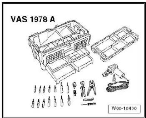
Notes on repairs to CAN bus wiring page 90
Notes on replacement of aerial cables page 90
Notes on repairs to wiring with cross sections up to 0.35 mm ^2 ⇒ page 91
Notes on repair of wiring open circuit with one repair position page 94
Notes on repair of wiring open circuit with two repair positions page 96
2.4.1 Notes on repairs to airbag and belt tensioner wiring
In addition to the general notes on repairs to wiring harnesses, the following instructions must be observed on how to repair wiring in airbag and belt tensioner systems:

WARNING
◆ Airbag and seat belt tensioner can fail.
- Faulty repairs to the airbag and seat belt tensioning system can cause malfunctions in the passenger protection system.
For repairs to airbag and belt tensioner wiring harnesses, only contacts, connectors and wiring designed specifically for this purpose may be used → Electronic parts catalogue (ETKA).
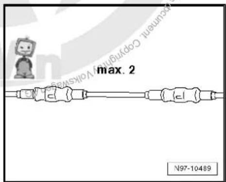
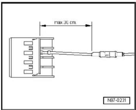

Note
◆ Wires from airbag and belt tensioner wiring harness are only allowed to be repaired using wiring harness repair set -VAS 1978 B- and previous versions.
Observe the general notes on repairs to the vehicle electrical system page 85.
Observe vehicle stickers indicating high voltage components. Before carrying out repairs, discharge residual voltage General body repairs, interior; Rep. gr. 69; Occupant safety.
For repairs to wiring in the airbag and belt tensioner system, a maximum of two positions may be repaired. The more the repairs there are in the wiring, the greater the resistance and this can trigger faults in the self-diagnosis of the system.
To avoid corrosion, the crimp connectors are always to be shrink-fitted when performing airbag or belt tensioner wiring harness repairs.
Do not incorporate the repaired wiring back in the vehicle's own wiring harness and mark the area of repair clearly with yellow insulating tape.
◆ Repairs in the area of the airbag or belt tensioner should not be more than 30 cm from the next contact housing. Together with the yellow insulating tape, this gives a clear indication of repairs that have already been carried out.
The wires to the triggering units (airbags) are entwined as standard with a twine spacing of 20 mm ± 5. This spacing is assured for series production via industrial standard numbers for wiring pairs and it is essential that it is adhered to on the repair lengths of entwined wiring.
During repairs, the wiring to the triggering units (airbags) must have the same length. When wires -1- and -2- are entwined, the twine spacing of A = 20 mm ± 5 must be adhered to without fail.
There must not be any section of wiring, for example in the vicinity of crimp connectors -arrow-, longer than B = 100 mm with the wires not twisted.
2.4.2 Fibre optic cables (FOC)
There is no provision for fibre optic cable repairs at Volkswagen. In the event of repairs, the entire fibre optic wiring harness must be replaced. To do this, the following safety precautions must be observed:

Note
- Avoid sharp bends in the fibre optic cable; the bend radius should be no tighter than 25 mm.
◆ Do not route fibre optic cables over sharp edges.
◆ The end pieces (lenses) must not be made dirty or touched with bare hands.
◆ Do not expose fibre optic cables to heat.
◆ Entwining two fibre optic cables or a fibre optic cable with a copper wire is not permissible.
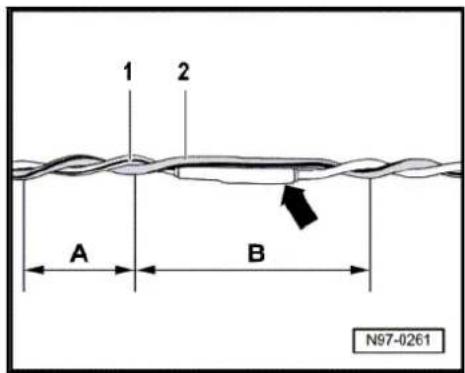
2.4.3 Repairs to CAN bus wiring
An unshielded two-wire line -1- and -2- with a cross section of 0.35 mm ^2 or 0.5 mm ^2 is used for CAN bus wiring.
◆ The colour codes of the CAN bus wiring can be gleaned from the following table:
| Powertrain CAN, high wire | Orange/black |
| Convenience CAN, high wire | Orange/green |
| Infotainment CAN, high | Orange/violet |
| CAN low wire, (all) | Orange/brown |
◆ Repairs to CAN bus wiring can be carried out either with sections of repair wiring with the correct cross section or with entwined wires „green/yellow“ or „white/yellow“ from the electronic parts catalogue (ETKA) ⇒ Electronic parts catalogue (ETKA).
When repairs are performed, both bus wires must have the same length. When twisting the wires -1- and -2- together, the length of each complete twist must be A ≈ 20 mm.
There must not be any section of wiring, for example in the vicinity of crimp connectors -arrow-, longer than B = 50 mm with the wires not twisted.
◆ Mark the area of repair with yellow insulation tape to make it easy to identify.
2.4.4 Renewal of aerial wiring
A new repair concept has been developed for repair work on aerial wires. Now connecting wires in different lengths and various adapter cables are available as replacement parts instead of a complete aerial wire.
General description:
◆ Aerial wires must not be repaired, but if repair is required, they must be replaced only by connecting wires and adapter cables offered as genuine parts.
◆ Replacement parts can be found in the ⇒ Parts catalogue (ETKA): Special catalogue; Electrical connections; Genuine accessories; Subgroup 35 from illustration No. 035-20.
◆ These genuine parts are suitable for all aerial wires and wire diameters which may need to be replaced.
◆ The connector housings for aerial wires are only available as genuine parts in one colour. However, they can be used for all colours of aerial connector.
◆ No provision has been made for replacement of individual aerial connectors in the event of repair.
◆ The wires can be used retroactively for all VW models, with all installed aerial wire diameters.
◆ All adapter and connection wires are suitable for all transmitter and receiver signals.
◆ This repair method can also be used for testing or retrofitting.
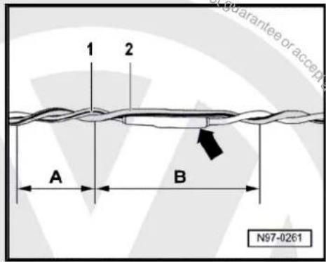

Assembly overview of aerial cable:
Example: aerial wire between radio and aerial is defective. The following wires are required for the repair:
1 - Adapter cable, to radio connection. Length approx. 30 cm.
2 - Connecting wire, available in different lengths.
3 - Adapter cable, to aerial connection. Length approx. 30 cm.
Installing a new aerial cable:

Note
Note that the total length of an aerial wire, depending on vehicle equipment level, can be divided into sections by aerial diversity control unit, traffic information control unit or aerial amplifier. Only the defective section of aerial wire must be replaced.
– Pull defective aerial wire connections off units.
- Determine the routing of the defective aerial wire in vehicle and measure the total length of the aerial connecting wire to be replaced.
The total length of aerial connecting wire is the sum of the length of adapter cables required -1- and -3- and the connecting wire -2-.
- To determine the length of connecting wire required, subtract 60 cm from the measured total length of aerial connecting wire -2-.
- Procure the required adapter cables -1- and -3- and connecting wire -2- at length calculated as genuine part from the Electronic parts catalogue (ETKA).
- Cut off connectors of defective aerial wire.
The remainder of the defective aerial wire remains in the vehicle.
- Connect adapter cables -1- and -3- to equipment in vehicle.
- Route and attach the connection line -2- in the immediate vicinity of the factory routing.

Note
Do not kink or excessively bend aerial wires! The bending radius must not be below 50 mm.
- Connect connecting wire to adapter cables.
- Perform functional test.
2.4.5 Repairs to wiring with cross sections up to 0.35 mm ^4
Special tools and workshop equipment required
◆ Crimping pliers, complete -VAS 1978/1 A-
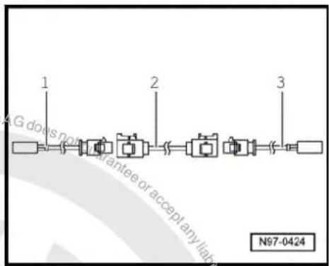
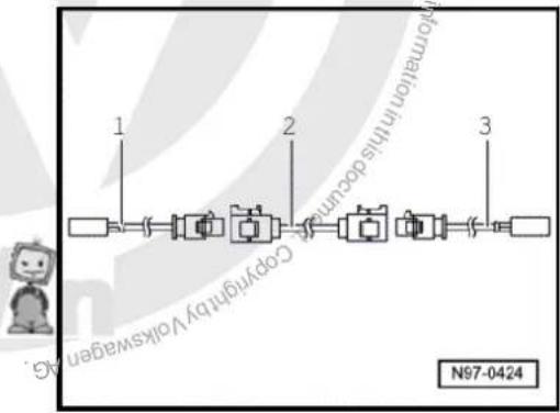
flowchart
graph LR
    A["1"] --> B["2"]
    B --> C["3"]
    style A fill:#fff,stroke:#000
    style B fill:#fff,stroke:#000
    style C fill:#fff,stroke:#000
    note right of B: Copyright by Volkswagen AG.
    note right of C: Copyright by Volkswagen AG.
    note right of D: Copyright by Volkswagen AG.
    note right of E: Copyright by Volkswagen AG.
    note right of F: Copyright by Volkswagen AG.
    note right of G: Copyright by Volkswagen AG.
    note right of H: Copyright by Volkswagen AG.
    note right of I: Copyright by Volkswagen AG.
    note right of J: Copyright by Volkswagen AG.
    note right of K: Copyright by Volkswagen AG.
    note right of L: Copyright by Volkswagen AG.
    note right of M: Copyright by Volkswagen AG.
    note right of N: Copyright by Volkswagen AG.
    note right of O: Copyright by Volkswagen AG.
    note right of P: Copyright by Volkswagen AG.
    note right of Q: Copyright by Volkswagen AG.
    note right of R: Copyright by Volkswagen AG.
    note right of S: Copyright by Volkswagen AG.
    note right of T: Copyright by Volkswagen AG.
    note right of U: Copyright by Volkswagen AG.
    note right of V: Copyright by Volkswagen AG.
    note right of W: Copyright by Volkswagen AG.
    note right of X: Copyright by Volkswagen AG.
    note right of Y: Copyright by Volkswagen AG.
    note right of Z: Copyright by Volkswagen AG.
    note right of AA: Copyright by Volkswagen AG.
    note right of AB: Copyright by Volkswagen AG.
    note right of AC: Copyright by Volkswagen AG.
    note right of AD: Copyright by Volkswagen AG.
    note right of AE: Copyright by Volkswagen AG.
    note right of AF: Copyright by Volkswagen AG.
    note right of AG: Copyright by Volkswagen AG.
    note right of AH: Copyright by Volkswagen AG.
    note right of AI: Copyright by Volkswagen AG.
    note right of AJ: Copyright by Volkswagen AG.
    note right of AK: Copyright by Volkswagen AG.
    note right of AL: Copyright by Volkswagen AG.
    note right of AM: Copyright by Volkswagen AG.
    note right of AN: Copyright by Volkswagen AG.
    note right of AO: Copyright by Volkswagen AG.
    note right of AP: Copyright by Volkswagen AG.
    note right of AQ: Copyright by Volkswagen AG.
    note right of AR: Copyright by Volkswagen AG.
    note right of AS: Copyright by Volkswagen AG.
    note right of AT: Copyright by Volkswagen AG.
    note right of AU: Copyright by Volkswagen AG.
    note right of AV: Copyright by Volkswagen AG.
    note right of AW: Copyright by Volkswagen AG.
    note right of AX: Copyright by Volkswagen AG.
    note right of AY: Copyright by Volkswagen AG.
    note right of AZ: Copyright by Volkswagen AG.
    note right of BA: Copyright by Volkswagen AG.
    note right of BB: Copyright by Volkswagen AG.
    note right of BC: Copyright by Volkswagen AG.
    note right of DA: Copyright by Volkswagen AG.
    note right of AE: Copyright by Volkswagen AG.
    note right of AF: Copyright by Volkswagen AG.
    note right of AWG: Copyright by Volkswagen AG.
    note right of AXG: Copyright by Volkswagen AG.
    note right of AZG: Copyright by Volkswagen AG.
    note right of BAAGG: Copyright by Volkswagen AG.
    note right of CAAGG: Copyright by Volkswagen AG.
    note right of AZAGG: Copyright by Volkswagen AG.
    note right of BAAGG: Copyright by Volkswagen AG.
    note right of AAGG: Copyright by Volkswagen AG.
    note right of AZAGG: Copyright by Volkswagen AG.
    note right of AAGG: Copyright by Volkswagen AG.
    note right of AZAGG: Copyright by Volkswagen AG.
    note right of AAGG: Copyright by Volkswagen AG.
    note right of AZAGG: Copyright by Volkswagen AG.
◆ Head adapter 0.35 mm² - 2.5 mm² - VAS 1978/1-1-
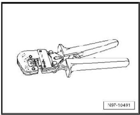
natural_image
Line drawing of a wire crimping tool with no visible text or symbolsFor repairs to wiring with cross sections up to 0.35 mm ^2 , it is essential that contacts are crimped on using crimping pliers for JPT contacts -VAS 1978/9A- or crimping pliers (base tool) -VAS 1978/1-2- with attached head adapter for JPT contacts -VAS 1978/9-1-. Due to the low current strength of these wires in the micro and thousandths range, incorrectly crimped contacts cause electrical resistances and result in faults or failure in the respective system. The most common applications of these contacts are:
◆ Lambda probe
◆ Engine speed sender
Air mass meter
With the use of crimping pliers for JPT contacts -VAS 1978/9A- or crimping pliers (base tool) -VAS 1978/1-2- with attached head adapter for JPT contacts -VAS 1978/9-1-, the correct connection between crimp contact, wire and single wire seal is assured. The tool is only to be used for the application described.

Note
Crimped to the repair wiring are normal contacts and gold-plated contacts. The repair contact must always be the same type as the contact installed in the factory.
Crimping on new contact with single wire seal
- Insert head adapter for JPT contacts -VAS 1978/9-1- in crimping pliers (base tool) -VAS 1978/1-2- page 84.
- Attach the single wire seal to the repair wire.

Note
When doing this, the small diameter of the single wire seal must face the contact to be crimped on.
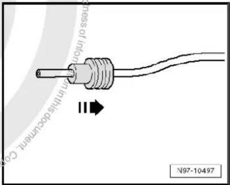
- Open the crimping pliers and insert the end of the repair wire in the opening of the crimping pliers for wire stripping.
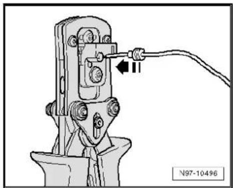
natural_image
Mechanical assembly diagram showing a clamp or clamp device with a wire and connector (no text or symbols visible)- Close the crimping pliers fully.
- Open the crimping pliers again and removed the stripped wire end.
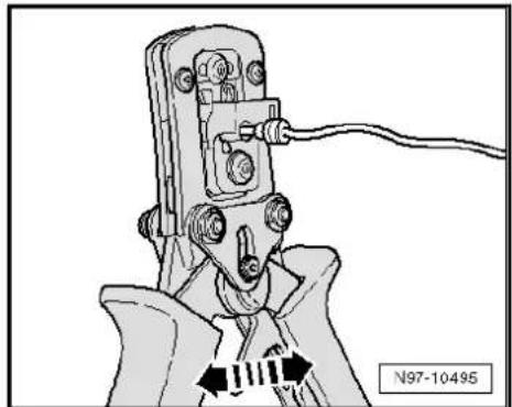
natural_image
Mechanical clamp or tool assembly diagram showing a clamping mechanism with no visible text or symbols- Push the single wire seal towards the stripped wire end until it is flush with the wiring insulation.
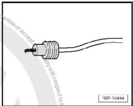
- Insert the new crimp contact in the mounting of the crimping pliers.
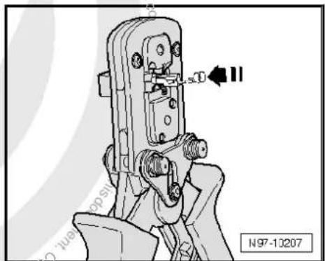

- Insert the stripped wire end with the positioned single wire seal in the crimp contact until it comes into contact with the „wire stop“.
- Crimp the contact, wire and single wire seal by closing the crimping pliers fully.
- Open the crimping pliers again and remove the successfully crimped contact.
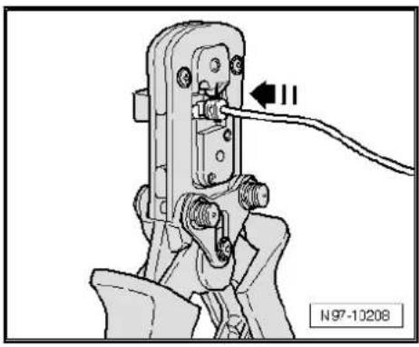
natural_image
Mechanical assembly diagram showing a clamp or crimping tool with a cable and labeled section (N97-10208), no readable text or symbols beyond the label.Successful crimping can be identified by clean and equal application of pressure on the wire and single wire seal in the contact and by a stamp on the rear that indicates the correct tool was used in the correct manner to carry out the crimping process.
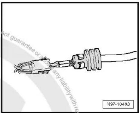
2.4.6 Wiring open circuit with one repair position
Repair position with single crimp connector
- Place the wire to be repaired to one side (about 20 cm either side of the repair position).
- If necessary, unbind the wiring harness using the folding knife.
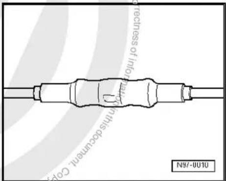
- Cut out the damaged piece of wiring using the wire strippers - VAS 1978/3-.
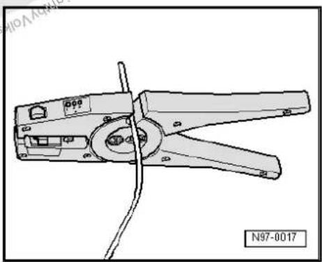
natural_image
Technical line drawing of a wire crimping tool (no text or symbols on the diagram itself)
Note
If, after the damaged wire has been cut out, both ends of the vehicle's own wiring are too short for a repair using single crimp connectors, use a piece of repair wire of the appropriate length with two crimp connectors page 96.
- Strip the wire ends of insulation by 6 - 7 mm using the wire strippers.
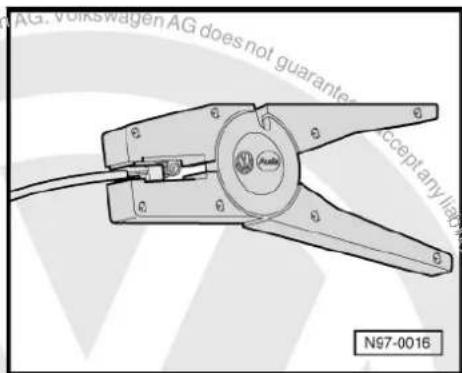
- Push the crimp connector on both stripped wire ends of the vehicle's own single wire and crimp it on using the crimping pliers.

Note
◆ Ensure without fail that the correct crimp recess is chosen for the crimp connectors being used → page 82.
◆ The insulation on the wires must not be crimped.
After crimping, the crimp connector has to be shrink fitted using the hot air blower in order to prevent any ingress of moisture.
- Place shrink element for hot air blower -VAS 1978/15- on hot air blower, 220 V / 50 Hz -VAS 1978/14-.
- Heat up the crimp connector using the hot air blower along a straight line, working from the middle outwards, until it is sealed completely and the adhesive escapes from the ends.

Caution
When shrink-fitting, take care not to damage any other wiring, plastic parts or insulating material with the hot air blower.
Observe the operating instructions of the hot air blower without fail!
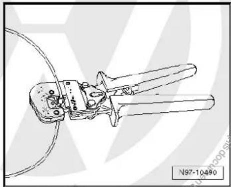
natural_image
Technical line drawing of a wire crimping tool with attached components (no text or symbols)
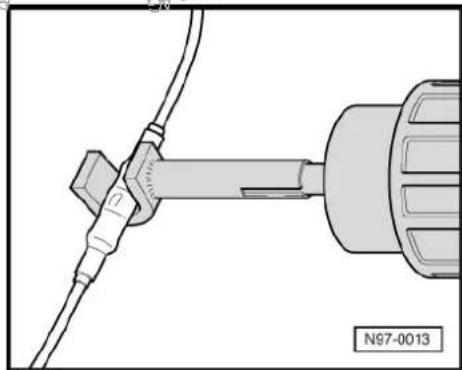
natural_image
Technical diagram of a mechanical assembly with a tool and cable (no text or symbols)
Note
◆ Ensure that, where several wires have to be repaired, the crimp connectors are not directly adjacent to each other. To prevent the circumference of the wiring harness from becoming to great, position the crimp connectors so they are offset slightly.
If the repair position was already wrapped, this section has to be wrapped again with yellow insulation tape once the repair has been carried out.
◆ Attach the repaired wiring harness with a cable tie, if necessary, to prevent it from generating noise when the vehicle is in motion.
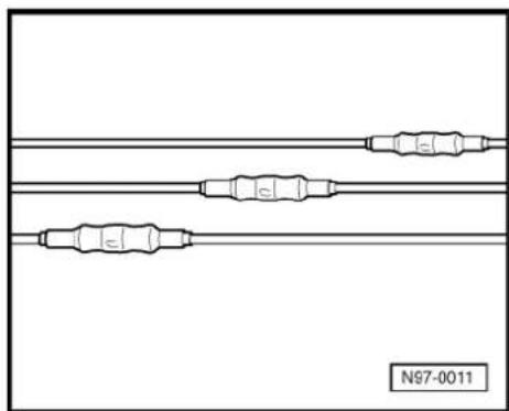
natural_image
Pure electrical circuit lines without any symbols2.4.7 Wiring open circuit with two repair positions
Repair position with interlinked wire.
- Place the wire to be repaired to the side at two points (about 20 cm to both sides of the relevant repair position).
- If necessary, unbind the wiring harness using the folding knife.
- Place the yellow repair wire next to the damage wiring harness and, using wire strippers -VAS 1978/3-, cut the repair wire to the required length. - Cut the damaged section of wire out of the vehicle's own single wire.
- Strip the wire ends of insulation by 6 - 7 mm using the wire strippers. - Push the crimp connector onto one side of the vehicle's own single wire and on the other side onto the repair wire.
- Crimp the connector using the crimping pliers to both wire ends. - Repeat this procedure on the other end of the repair wire.

Note
◆ Ensure without fail that the correct crimp recess is chosen for the crimp connectors being used ⇒ page 82.
◆ The insulation on the wires must not be crimped.
After crimping, the crimp connector has to be shrink fitted using the hot air blower in order to prevent any ingress of moisture.
- Place shrink element for hot air blower -VAS 1978/15- on hot air blower, 220 V / 50 Hz -VAS 1978/14-.
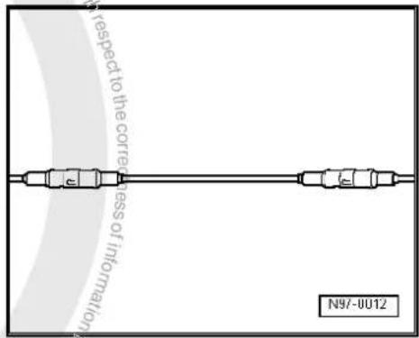
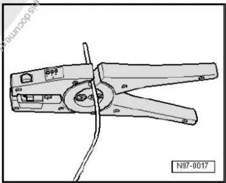
natural_image
Technical line drawing of a wire crimping tool (no text or symbols on the diagram itself)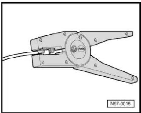
natural_image
Technical line drawing of a mechanical clamp or crimping tool with no visible text or symbols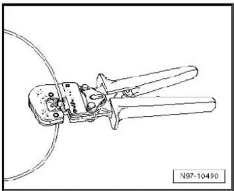
natural_image
Technical line drawing of a wire crimping tool with no visible text or symbols- Heat up the crimp connector using the hot air blower along a straight line, working from the middle outwards, until it is sealed completely and the adhesive escapes from the ends.

Caution
When shrink-fitting, take care not to damage any other wiring, plastic parts or insulating material with the hot air blower.
Observe the operating instructions of the hot air blower without fail!
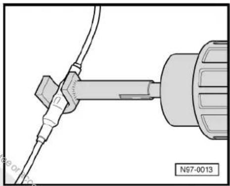
natural_image
Technical diagram of a mechanical assembly with a tool and connector (no text or symbols)
Note
◆ Ensure that, where several wires have to be repaired, the crimp connectors are not directly adjacent to each other. To prevent the circumference of the wiring harness from becoming to great, position the crimp connectors so they are offset slightly.
If the repair position was already wrapped, this section has to be wrapped again with yellow insulation tape once the repair has been carried out.
◆ Attach the repaired wiring harness with a cable tie, if necessary, to prevent it from generating noise when the vehicle is in motion.
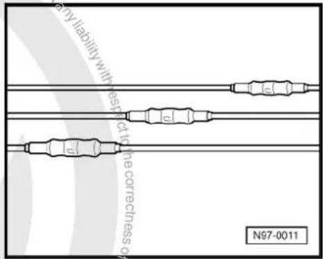
2.5 Repairs to contact housings and connectors
2.5.1 Notes on repairs to contact housings and connectors

Note
Observe the general notes on repairs to the vehicle electrical system page 85.
♦ Allocation of the appropriate crimp contacts to the contact housings is by way of the part number stamped on the contact housing. Listed in illustration 198 (electrical connecting elements) in → Electronic parts catalogue (ETKA) are the part numbers for the contact housings in conjunction with the associated crimp contacts.
◆ Damaged contact housings must always be replaced.
◆ New contact housings can be ordered from the OTC in Kassel.
2.5.2 Repairs to contacts in contact housings
- If necessary, first open or disengage the secondary locking mechanism of the contact housing page 102.
- Disengage the contact (primary locking mechanism) using the appropriate release tool page 102.
– Pull the contact by the single wire out of the contact housing. - Select the yellow repair wire with the correct contact from the wiring harness repair set.
- Place the wire to be repaired from the vehicle's own wiring harness to one side (about 20 cm either side of the repair position).
- If necessary, unbind the wiring harness using the folding knife.
- Push the new contact of the repair wire into the contact housing until it engages.
- Slide the single wire seal onto the repair wire.

Note
The small diameter of the single wire seal must face the contact housing.
- Slide the single wire seal into the contact housing using the correct assembly tool page 99.
- Trim the repair wire and the single wire of the vehicle's own wiring harness accordingly using wire strippers -VAS 1978/3-.
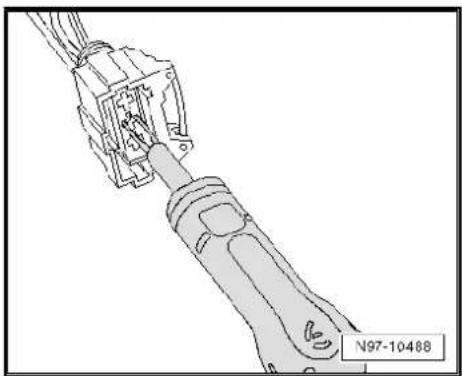
natural_image
Technical line drawing of a mechanical assembly with no visible text or symbols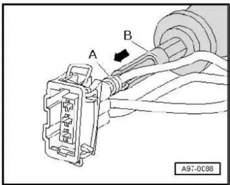
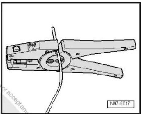
natural_image
Line drawing of a wire crimping tool with two blades and a handle, no text or symbols present- Strip the 6 ^2 - 7 mm of insulation from the end of the repair wire and the vehicle's own single wire using the wire strippers.
- Crimp the stripped ends of the repair wire and single wire of the vehicle's own wiring harness using the crimping pliers and a crimp connector, as described in the chapter entitled „Wiring open circuits with one repair position“ ⇒ page 94.
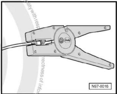


Note
◆ Ensure that, where several wires have to be repaired, the crimp connectors are not directly adjacent to each other. To prevent the circumference of the wiring harness from becoming to great, position the crimp connectors so they are offset slightly.
If the repair position was already wrapped, this section has to be wrapped again with yellow insulation tape once the repair has been carried out.
◆ Attach the repaired wiring harness with a cable tie, if necessary, to prevent it from generating noise when the vehicle is in motion.
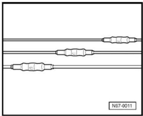
natural_image
Pure electrical circuit lines without any symbols2.5.3 Fitting single wire seals

Note
Single wire seals prevent the ingress of moisture and dirt in the contact housing. They are installed, for example, in the engine compartment and must always be reinstalled following repairs.
As standard, the single wire seal is crimped together with the contact on the wire; this is not the case with the repair wires. Before crimping the repair line, the single wire seal must therefore first be pushed onto the wire.
It is essential that the single wire seals are of the correct size to fit the cross section of the repair wire. The outer diameter of the single wire seal is based on the socket diameter of the contact housing. Only carry out the repair using the correct assembly tool.
Assembling single wire seal:
- Disengage the contact locking mechanism using the appropriate release tool -A- and then pull the wire with the single wire seal backwards -arrow- out of the contact housing.
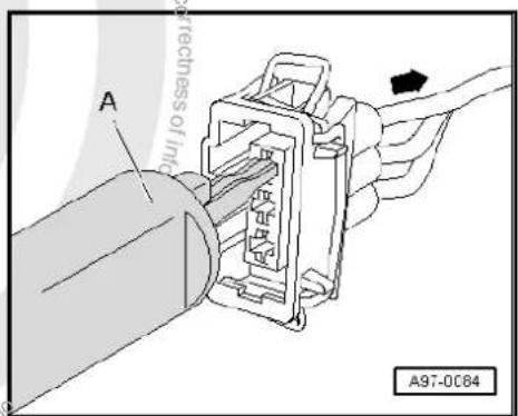
- Cut off the old contact with the single wire seal from the vehicle's own wiring harness.
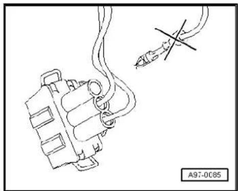
natural_image
Technical line drawing of a mechanical component with a tool and cross mark (no text or symbols)- Slide the repair wire with the new contact in the respective socket of the contact housing until it engages.
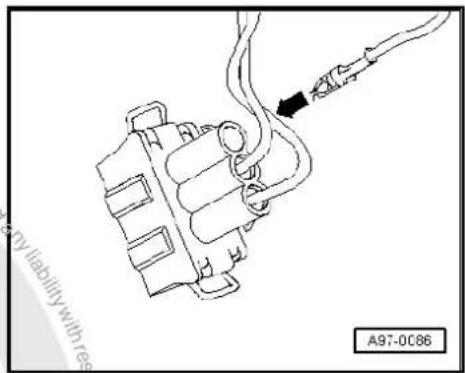
- Place the single wire seal -A- on the free end of the repair wire.

Note
The small diameter of the single wire seal must face the contact housing.
- Slide the single wire seal -A- on the repair wire until it reaches the contact housing.
- Slide the single wire seal -A- using the respective assembly tool -B- fully into the contact housing.
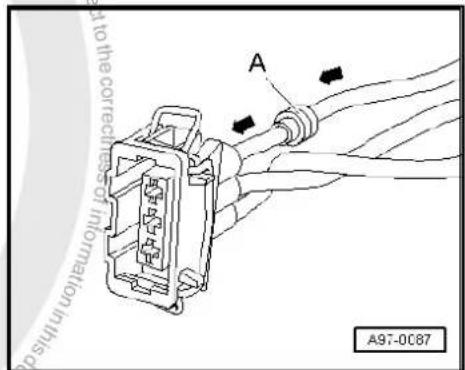
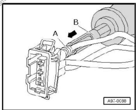
- Trim the repair wire and the single wire of the vehicle's own wiring harness accordingly using wire strippers -VAS 1978/3-.
- Crimp the stripped ends of the repair wire and single wire of the vehicle's own wiring harness using the crimping pliers and a crimp connector, as described in the chapter entitled „Wiring open circuits with one repair position“ ⇒ page 94.
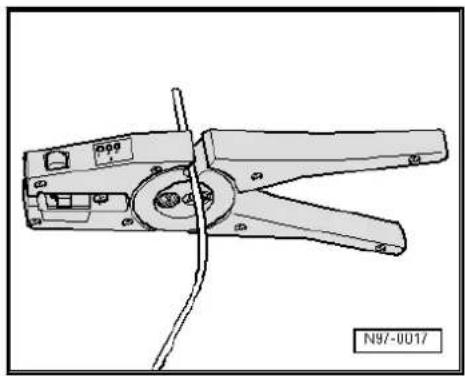
natural_image
Technical line drawing of a wire crimping tool (no text or symbols on the component itself)2.5.4 Repairs to contact housings using cut and clamp technique

Note
For technical reasons, the contact housings for cut and clamp technique can only be supplied with the cut and clamp contacts inserted.
These contacts can be removed just like any other contact housing if they are not needed.
◆ Repair wires can be supplied that already have the appropriate contacts crimped on → Electronics parts catalogue (ETKA).
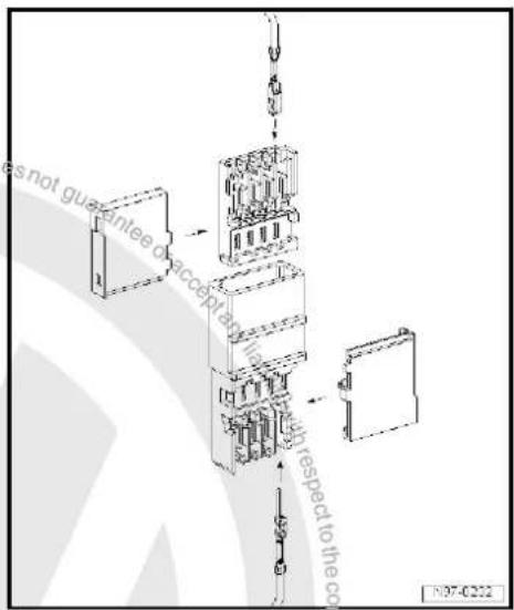
2.6 Releasing and dismantling contact housings
2.6.1 Notes on releasing and dismantling contact housings

Note
Observe the general notes on repairs to the vehicle electrical system page 85.
◆ To release, always use the correct release tools. Under no circumstances should the contacts be pulled out of the contact housings with force.
◆ Damaged contact housings must always be replaced. New contact housings can be ordered from the OTC in Kassel.
As an aid to disengage the secondary locking mechanisms, a small screwdriver can be used.
The socket/pin assignment can be found stamped on the secondary locking mechanism or on the rear of the contact housing.
For more detailed information about the locations of connectors, see Current flow diagrams, Electrical fault finding and Fitting locations.
Allocation of the correct release tool to the respective locking devices can be gleaned from the table in the operating instructions of -VAS 1978/35-.

2.6.2 Secondary locking element
The secondary locking mechanism is a housing catch (second line locking mechanism) that secures all the wires in one contact housing. If a secondary locking mechanism is fitted to a contact housing, this must always be opened or removed using the appropriate tool before releasing and pulling out individual crimp contacts.
The secondary locking mechanism is different in colour from the rest of the contact housing. This makes it easier to identify the secondary locking mechanism and clarifies its intended function.
The types of contact housing shown here are just a few examples to show the different functions of secondary locking mechanism.
Example 1:
The housing catch is disengaged by removing a "toothed element"-arrow-.
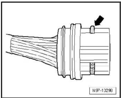
natural_image
Technical line drawing of a mechanical component with no visible text or symbolsExample 2:
The housing catch is disengaged by opening a „flap“ -arrow-.
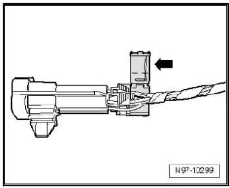
natural_image
Technical diagram of a mechanical assembly with a directional arrow indicating movement (no text or symbols present)Example 3:
The housing catch can be disengaged by detaching a „slide“-arrow-.
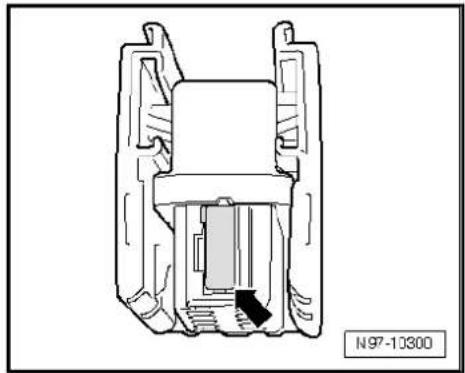
natural_image
Technical line drawing of a mechanical component with no visible text or symbols2.6.3 Primary locking element
The primary locking mechanism is what fixes an individual crimp contact in the contact housing.
If necessary, any housing catches in place (secondary locking mechanisms) must be released or removed prior to disengaging the contacts using the prescribed tool ≥ page 102.
The types of primary locking mechanisms shown as follows are just a few examples to show the different functions of primary locking mechanism.
◆ Round connector systems → page 103
◆ Flat connector systems ⇒ page 104
◆ Special connector systems ⇒ page 106
Allocation of the correct release tool to the respective locking device can be gleaned from the table in the operating instructions of -VAS 1978/35-.
2.6.4 Round connector systems

Note
If necessary, any housing catches in place (secondary locking mechanisms) must be released or removed prior to disengaging the contacts using the prescribed tool page 102.
- Insert the release tool appropriate for the contact housing in the release port of the contact housing.
- Grab hold of the contact by the wire and push it lightly into the contact housing -arrow-.

Note
By pushing the contact in the direction of the contact housing, the locking tabs of the contact are lifted up by the housing edge and disengaged using the release tool.
- At the same time, push the release tool in the direction of the contact housing -arrow- and pull out the released contact from the contact housing.
- The release tool can be pulled out of the contact housing again once the contact has been removed.
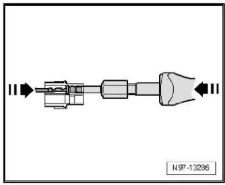
natural_image
Mechanical component diagram showing a shaft and housing assembly with directional arrows (no text or symbols)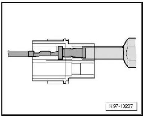
natural_image
Technical cross-sectional diagram of a mechanical assembly (no text or symbols visible)2.6.5 Flat connector systems

Note
If necessary, any housing catches in place (secondary locking mechanisms) must be released or removed prior to disengaging the contacts using the prescribed tool page 102.
Flat connector with one locking tab:
- Insert the release tool appropriate for the contact housing in the release port of the contact housing.
- Grab hold of the contact by the wire and push it lightly into the contact housing -arrow-.

Note
By pushing the contact in the direction of the contact housing, the locking tab of the contact is lifted up by the housing edge and can be disengaged using the release tool.
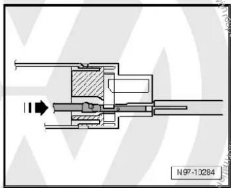
natural_image
Cross-sectional technical diagram of a mechanical assembly (no visible text or labels)
- At the same time, push the release tool in the direction of the contact housing and pull out the released contact from the contact housing -arrow-.
- The release tool can be pulled out of the contact housing again once the contact has been removed.
Flat connector with two locking tabs:
- Insert the release tool appropriate for the contact housing in the release port of the contact housing.
- Grab hold of the contact by the wire and push it fully into the contact housing -arrow-.

Note
By pushing the contact in the direction of the contact housing, the locking tabs of the contact are lifted up by the housing edge and disengaged using the release tool.
- At the same time, push the release tool in the direction of the contact housing and pull out the released contact from the contact housing -arrow-.
- The release tool can be pulled out of the contact housing again once the contact has been removed.
Asymmetrical:
- Insert the release tool appropriate for the contact housing in the release port of the contact housing.
- Grab hold of the contact by the wire and push it lightly into the contact housing -arrow-.

Note
By pushing the contact in the direction of the contact housing, the locking tabs of the contact are lifted up by the housing edge and disengaged using the release tool.
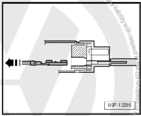
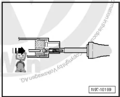
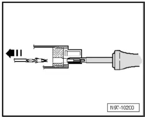
natural_image
Technical diagram of a mechanical assembly with no visible text or symbols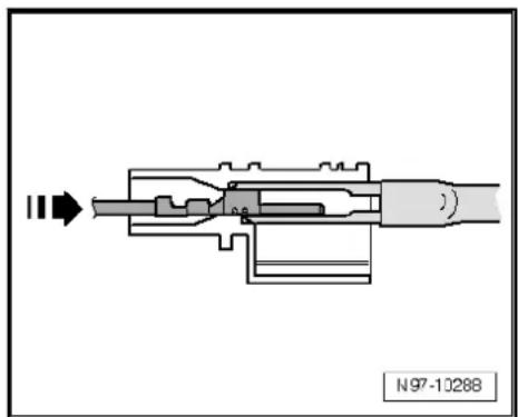
natural_image
Cross-sectional diagram of a mechanical device with internal components and directional arrow (no text or symbols)- At the same time, push the release tool in the direction of the contact housing and pull out the released contact from the contact housing -arrow-.
- The release tool can be pulled out of the contact housing again once the contact has been removed.
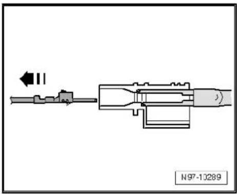
natural_image
Mechanical assembly diagram showing a shaft and housing with directional arrows (no text or symbols)2.6.6 Special connector systems

Note
If necessary, any housing catches in place (secondary locking mechanisms) must be released or removed prior to disengaging the contacts using the prescribed tool → page 102.
Faston contacts:
- Insert the release tool appropriate for the contact housing in the release port of the contact housing.
- Grab hold of the contact by the wire and push it lightly into the contact housing.

Note
By pushing the contact in the direction of the contact housing, the locking tabs of the contact are lifted up by the housing edge and disengaged using the release tool.
- At the same time, push the release tool in the direction of the contact housing and pull out the released contact from the contact housing -arrow-.
- The release tool can be pulled out of the contact housing again once the contact has been removed.
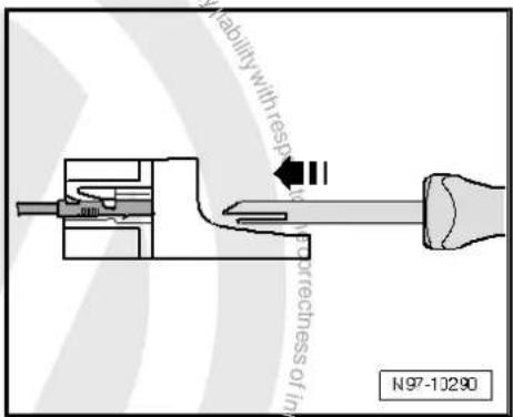
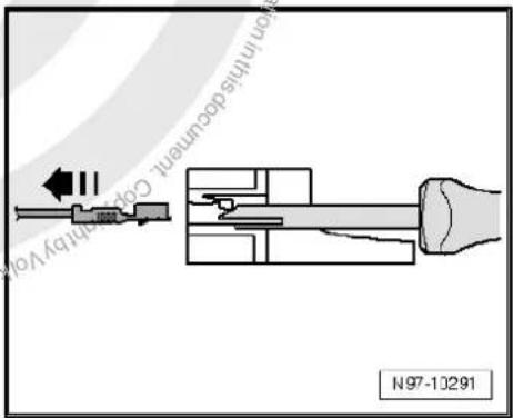

GT 150/280 contacts:
- Insert the release tool appropriate for the contact housing under the locking tab into the contact housing.
- Push the tool onto the limit stop -arrow- in the contact housing.
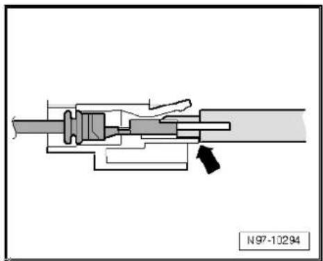
natural_image
Mechanical assembly diagram showing internal components and a directional arrow (no text or symbols)The contact is ejected from the contact housing.
- The release tool can be pulled out of the contact housing again once the contact has been ejected.
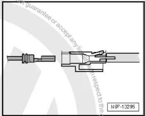
Contacts without locking tabs:
- Insert the release tool under the locking tab of the contact housing.
- Push through the release tool with a light upward movement -arrow- onto the limit stop.
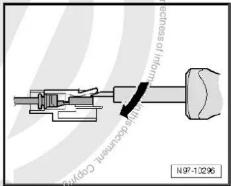
The contact is ejected from the contact housing.

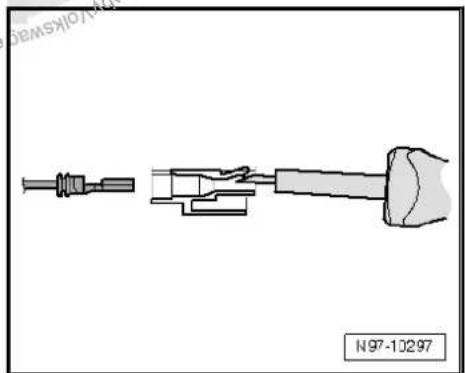
natural_image
Technical line drawing of a mechanical component with no visible text or symbols3 Contact surface cleaning set -VAS 6410-
3.1 Using contact surface cleaning set -VAS 6410-
The contact surface cleaning set -VAS 6410- allows optimal repair quality to be achieved in the area of vehicle electrics. The tools allow performing repair work in the area of the sensor in wiring harnesses for threaded connections in the high-current circuit (starting and charging current). The contact surface cleaning set -VAS 6410- is adapted to the structural conditions of vehicles and ensures the process security of repair work as well as a comfortable procedure.

Note
The illustrations shown here are just a few examples of repair work.
Contact surface cleaning set VAS 6410
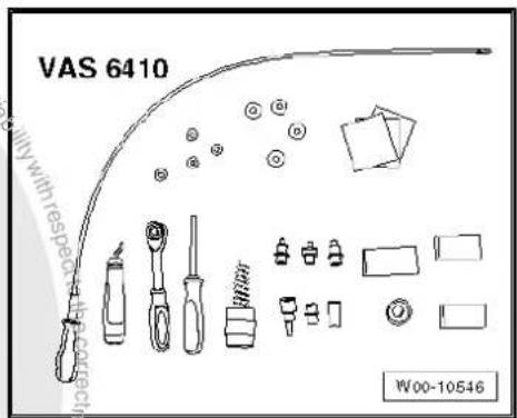
3.1.1 Repairing ring terminals
Special tools and workshop equipment required
VAG 1331
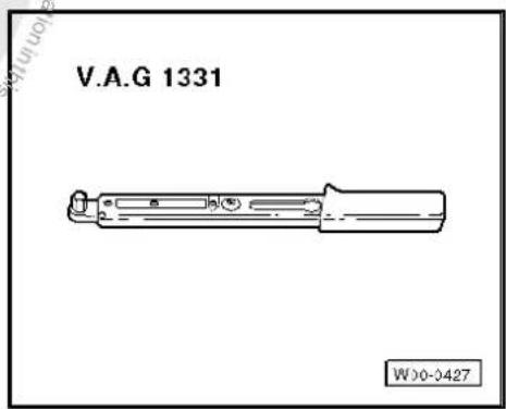

Note
The use of penetrating fluid, contact spray or grease etc. is prohibited since the missing adhesion in the threads may cause a torque excess and, therefore, the break of the threaded connection.
The grey sanding pads are suitable for light dirt and "soft surfaces". The red sanding pads are suitable for heavy dirt and "hard surfaces".

WARNING
Danger of injury! Observe warning notices and safety regulations page 2!
- Disconnect battery.
- Loosen cap nut and remove ring terminal from threaded connection.
- Check ring terminal for corrosion, dirt etc.
- Select suitable adapter and suitable sanding pad.

Note
As an alternative, the sanding block may also be used.

Caution
Take care not to abrade excessively the tin coating and ensure that the copper does not appear. This could produce a galvanic cell which destroys metal and causes faulty repair.
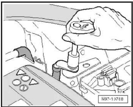
natural_image
Hand inserting a component into a vehicle engine compartment, showing parts like wheels and buttons (no text or symbols)
Note
As the thickness of the tin coating may differ according to the design, the cleaning process must be performed step by step and a visual check of the ring terminal is necessary between the steps.
- Insert adapter into ring terminal and grind off corrosion and dirt with circular movements.
- Check ring terminal and regrind if necessary.
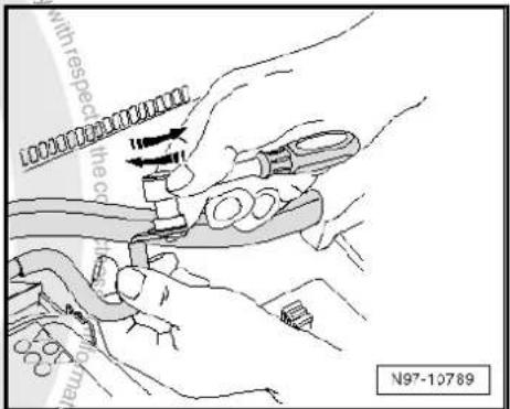

- If necessary, remove punching burr on ring terminal using the deburrer.
- Tighten ring terminal to specified torque Current flow diagrams, Electrical fault finding and Fitting locations.

Note
Optimum contact is ensured when the components to be secured are tightened to the specified torque after cleaning.
- Apply suitable anti-corrosion treatment to connection page 113.
- Reconnect battery.
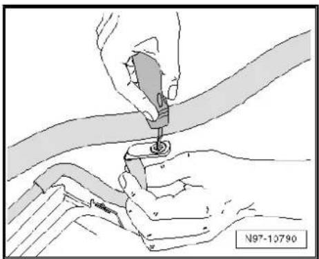
natural_image
Illustration of hands using a tool to adjust or install a component, no text or symbols present
WARNING
Danger of injury! Observe warning notices and safety regulations page 2!
- Teach in electric windows again, enter radio code, set clock and, if necessary, recode control units which emit code signals.
3.1.2 Repairing threaded connections
Special tools and workshop equipment required
VAG 1331
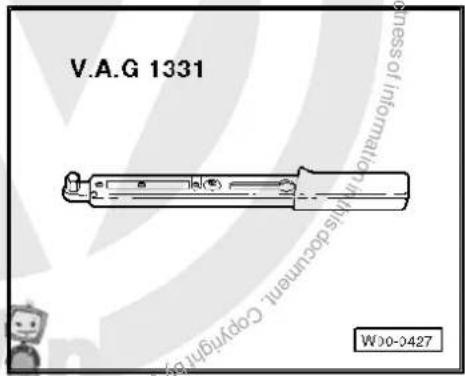

Note
The use of penetrating fluid, contact spray or grease etc. is prohibited since the missing adhesion in the threads may cause a torque excess and, therefore, the break of the threaded connection.
The grey sanding pads are suitable for light dirt and "soft surfaces". The red sanding pads are suitable for heavy dirt and "hard surfaces".

WARNING
Danger of injury! Observe warning notices and safety regulations ⇒ page 2 !
- Disconnect battery.
- Loosen cap nut and remove ring terminal from threaded connection.
- Check threaded connection for corrosion, dirt etc.
- Select suitable adapter and suitable sanding pad for threaded connection.

Caution
Take care not to abrade excessively the tin coating and ensure that the copper does not appear. This could produce a galvanic cell which destroys metal and causes faulty repair.
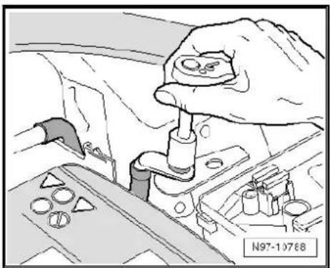
natural_image
Illustration of a hand adjusting a mechanical component with circular parts and a tool (no text or symbols visible)
Note
As the thickness of the tin coating may differ according to the design, the cleaning process must be performed step by step and a visual check of the ring terminal is necessary between the steps.
- Set adapter on threaded connection and grind off corrosion and dirt with circular movements.
- Check threaded connection and regrind if necessary.
- Tighten connection and, if necessary, locating element again to specified torque Current flow diagrams, Electrical fault finding and Fitting locations.

Note
Optimum contact is ensured when the components to be secured are tightened to the specified torque after cleaning.
- Apply suitable anti-corrosion treatment to threaded connection page 113.
- Reconnect battery.
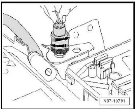
natural_image
Technical line drawing of a mechanical assembly with no visible text or symbols
WARNING
Danger of injury! Observe warning notices and safety regulations ⇒ page 2 !
- Teach in electric windows again, enter radio code, set clock and, if necessary, recode control units which emit code signals.
3.1.3 Cleaning battery clamp and battery terminal
Special tools and workshop equipment required
◆ VAG 1331
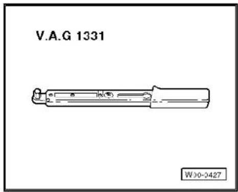

Note
The use of penetrating fluid, contact spray or grease etc. is prohibited since the missing adhesion in the threads may cause a torque excess and, therefore, the break of the threaded connection.

WARNING
Danger of injury! Observe warning notices and safety regulations ⇒ page 2 !
- Disconnect battery.
- Check battery clamp and battery terminal for corrosion or dirt.
- Clean battery clamp using wire brush of battery terminal cleaner with circular movements.
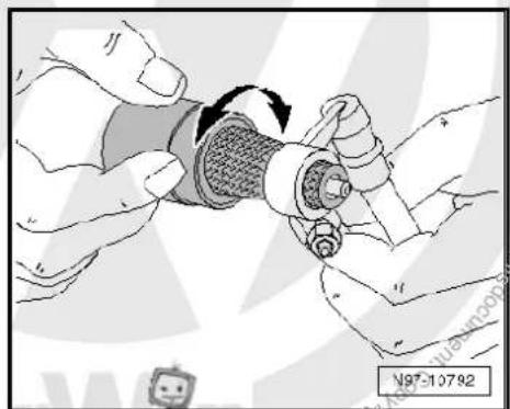
natural_image
Illustration of hands holding a mechanical component with a circular arrow indicating rotation (no text or symbols)- Clean battery terminal using underside of battery terminal cleaner with circular movements.

WARNING
Danger of injury! Observe warning notices and safety regulations page 2!
- Reconnect battery and tighten battery terminals to specified torque.

Note
Optimum contact is ensured when the components to be secured are tightened to the specified torque after cleaning.
3.1.4 Anti-corrosion treatment

Caution
Missing anti-corrosion treatment results in damage to the on-board supply.

Note
◆ All threaded connections must be tightened to specified torque.
◆ Always use hose supplied with anticorrosive agent tin.
◆ Use protection wax for cold area.
◆ Use cavity sealing agent for warm area.
◆ The sealing agent independently reaches the respective points through capillary action.
- Hold injector below ring terminal and spray pin all around.
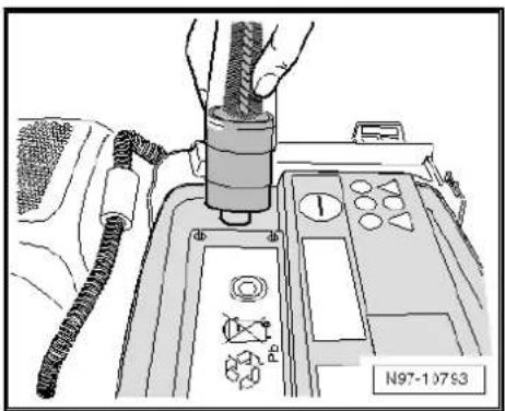
natural_image
Diagram of a vehicle's control panel with hoses and buttons, no readable text or symbols present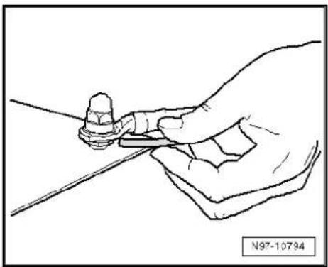
natural_image
Line drawing of a hand holding a tool with a small object, no text or symbols present- Hold injector above ring terminal and spray pin and wiring eye all around.

natural_image
Line drawing of a hand holding a small object over a line, no text or symbols present
4 Renewing Lambda probe

Note
Do not repair lambda probe wires, since this can result in malfunctions.
If necessary, replace attachment parts, cable ties or marking rings to match the uniform probe to the defective probe as specified.
Identify the lambda probe by way of the protective tube as required page 117.
4.1 Renewing LSF Lambda probe (4-pin)

Note
If necessary, replace attachment parts, cable ties or marking rings to match the uniform probe to the defective probe as specified.
Do not repair lambda probe wires, since this can result in malfunctions.
- Remove the defective Lambda probe.
- Place both Lambda probes next to each other so that the sensor housings are at the same height.
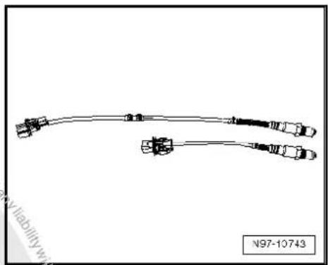
natural_image
Pure electrical circuit lines without any symbols
- Tie back any excess in the uniform probe length (approx. 50 - 250 mm) to the size of the defective probe and secure with cable ties -1-.
- Check that the connector housing of the Lambda probe is compatible with the onboard supply side.
- If necessary, replace the onboard supply system connector with the Lambda probe connector housing supplied page 97

Note
◆ The connector housing should only be replaced on older vehicles. On new vehicles, the connector housing coding matches.
◆ Observe pin assignment. For reasons of clarity, respective pins in new connector housing have a colour marking.
◆ Further notes can be found in the leaflet of the new lambda probe.
- Install the new Lambda probe in the vehicle.
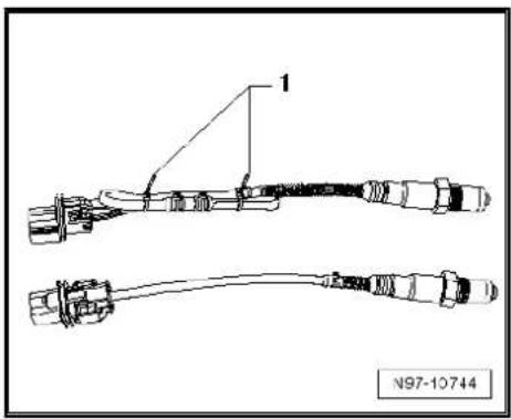
4.2 Renewing LSU Lambda probe (6-pin)

Note
If necessary, replace attachment parts, cable ties or marking rings to match the uniform probe to the defective probe as specified.
◆ The wires should not be crimped or cut as otherwise the function of the Lambda probe will be impaired.
- Remove the old Lambda probe.
- Place both Lambda probes next to each other so that the sensor housings are at the same height.
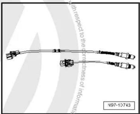

- Tie back any excess in the uniform probe length (approx. 50 - 250 mm) to the size of the defective probe and secure with cable ties -1-.
- Install the new Lambda probe in the vehicle.

natural_image
Technical line drawing of a mechanical component with labeled part '1' and reference number N97-10744 (no text or symbols on the diagram itself)4.3 Types of protective tube on uniform Lambda probes

Note
In addition to identifying by way of the part number, the protective tube can also be used as a means of identification.
Type D1, 6 openings at 3.5 mm each
Only used on 4-pin LSF Lambda probes.
Type D2, 6 openings at 2 mm each

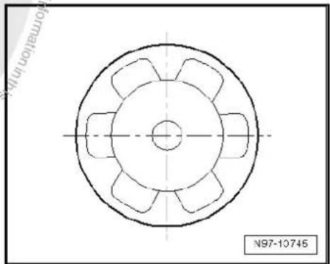
natural_image
Technical drawing of a mechanical component with symmetrical cutouts and centerlines (no text or symbols)Only used on 4-pin LSF Lambda probes and 6-pin LSU Lambda probes.
Type D4, 12 openings at 1.4 mm each
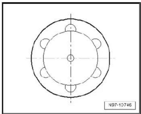
natural_image
Technical drawing of a circular mechanical part with symmetrical features and centerlines (no text or symbols)Only used on 4-pin LSF Lambda probes and 6-pin LSU Lambda probes.
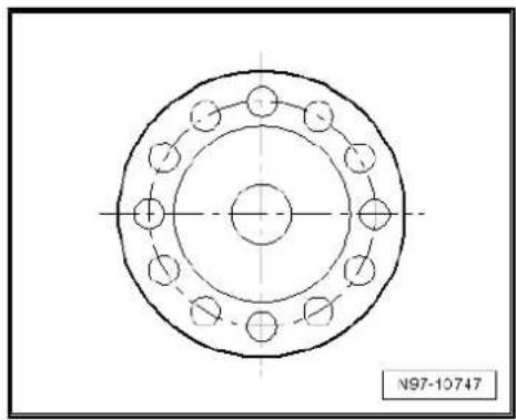

- List of Workshop Manual Repair GroupsList of Workshop Manual Repair GroupsList of Workshop Manual Repair Groups
- Repair Group
- Contents
- - Starter, current supply, CCS 1
- - Gauges, instruments 62
- - Windscreen wash/wipe system 63
- - Lights, bulbs, switches - exterior 68
- - Lights, bulbs, switches - interior 71
- 97-Wiring 78
- – Starter, current supply, CCS
- Battery
- Fundamentals for batteries
- Types of batteries
- Battery with magic eye
- Absorbent glass mat battery
- Warning notices and safety regulations
- Dangers when handling vehicle batteries
- WARNING
- Safety markings on battery
- Safety markings on battery
- Battery terminal connection
- Caution
- Checking battery
- Checking the various types of batteries
- Checking battery with magic eye
- Absorbent glass mat battery
- Visual check
- Performing this test establishes:
- Checking colour display of magic eye
- Checking colour display of „3-colour“ magic eye
- Note
- Checking colour display of „2-colour" magic eye
- Battery tester with printer -VAS 5097 A-
- Description of battery tester with printer -VAS 5097 A-
- Performing battery load test using battery tester with printer -VAS 5097 A-
- Table: cold cranking current
- Evaluating test result of battery load test
- Comments concerning test print out
- Assessing test results
- Battery tester with printer -VAS 6161-
- Description of battery tester with printer -VAS 6161-
- Perform battery test with battery tester with printer -VAS 6161-.
- Performing battery test:
- Performing maintenance test
- Perform service test
- Perform guarantee test
- Comments concerning test print out
- Assessing test results
- Midtronics -MCR340V- battery tester only for USA/Canada vehicles
- General description
- Performing battery test with Midtronics - MCR340V- battery tester
- Assessing test results
- Dealing with problems with Midtronics - MCR340V- battery tester
- Current draw test
- Test requirements
- Test result:
- Checking no-load voltage of battery on stock and stored vehicles
- Test conditions
- Charging battery
- Battery charger -VAS 5095 A-
- Description of battery charger -VAS 5095 A-
- Charging battery with battery charger - VAS 5095 A-
- Charging totally discharged battery with battery charger -VAS 5095 A
- Charging battery in support mode with battery charger -VAS 5095A-
- End battery support mode:
- Charging battery in maintenance mode with battery charger -VAS 5095 A-
- Battery charger -VAS 5900-
- Description of battery charger -VAS 5900-
- Charging battery with battery charger - VAS 5900-
- Possible faults and fault rectification
- Ending battery charging sequence:
- Charging battery in service mode with battery charger -VAS 5900-
- Possible faults and fault rectification:
- Charging totally discharged batteries with battery charger -VAS 5900-
- Charging battery in support mode with battery charger -VAS 5900-
- Charging battery in maintenance mode with battery charger -VAS 5900-
- Battery charger -VAS 5903-
- Description of battery charger -VAS 5903-
- Charging battery with battery charger - VAS 5903-
- Charging battery in refresh charge mode with battery charger -VAS 5903-
- Charging totally discharged battery with battery charger -VAS 5903-
- Charging battery in support mode with battery charger -VAS 5903-
- Charging battery in maintenance mode with battery charger -VAS 5903-
- Battery charger -VAS 5906-
- General description
- Charging battery with battery charger - VAS 5906-
- Overview of operating panel:
- Midtronics - INC 940- battery charger only for USA/Canada
- General description of Midtronics -INC 940- battery tester
- Charging battery
- Perform charging procedure:
- Dealing with problems with Midtronics - INC 940- battery tester
- Solar panel -VAS 6102A-
- Charging battery in maintenance mode with solar panel -VAS 6102A-
- Totally discharged batteries
- Cruise control system (CCS)
- Activating and deactivating cruise control system (CCS)
- – Gauges, instruments
- – Windscreen wash/wipe system
- Washer fluid line hose couplings
- Windscreen and rear window washer system
- Headlight washer system
- Hose repair
- General description
- Repairing smooth pipe
- Repairing corrugated pipe
- Distinguishing features of jointless wiper blades
- – Lights, bulbs, switches - exterior
- Operation and safety notes for gas discharge bulbs
- Repair notes for gas discharge bulbs
- Disposal regulations for gas discharge bulbs
- – Lights, bulbs, switches - interior
- 12 V socket
- Removing and installing 12 V socket
- Removing and installing socket illumination bulb -L42-
- Cigarette lighter -U1-
- Assembly overview
- Removing and installing cigarette lighter socket
- Removing
- Removing and installing cigarette lighter illumination bulb -L28-
- – Wiring
- Vehicle diagnostic, testing and information systems
- Connecting vehicle diagnostic tester
- Connecting vehicle diagnostic tester :
- Connecting vehicle diagnostic tester Golf Model Year 1998 - 2003
- Repairing wiring harnesses and connectors
- Wiring harness repair set
- Wiring harness repair set -VAS 1978-
- Upgrade kit -VAS 1978/50-
- Wiring harness repair set -VAS 1978A-
- Release tool set -VAS 1978/35-
- Tool descriptions
- Special pliers with insert
- Release tools for contacts
- Assembly tools for single wire seals
- Wire strippers -VAS 1978/3-
- Stripping:
- Hot air blower, 220 V / 50 Hz -VAS 1978/14-
- Crimping pliers -VAS 1978/1A-
- General notes concerning repairs to vehicle electrical system
- Repairs to wiring harnesses
- Notes on repairs to airbag and belt tensioner wiring
- Fibre optic cables (FOC)
- Repairs to CAN bus wiring
- Renewal of aerial wiring
- General description:
- Assembly overview of aerial cable:
- Repairs to wiring with cross sections up to 0.35 mm 4
- Wiring open circuit with one repair position
- Wiring open circuit with two repair positions
- Repairs to contact housings and connectors
- Notes on repairs to contact housings and connectors
- Repairs to contacts in contact housings
- Fitting single wire seals
- Assembling single wire seal:
- Repairs to contact housings using cut and clamp technique
- Releasing and dismantling contact housings
- Notes on releasing and dismantling contact housings
- Secondary locking element
- Example 1:
- Example 2:
- Example 3:
- Primary locking element
- Round connector systems
- Flat connector systems
- Flat connector with two locking tabs:
- Asymmetrical:
- Special connector systems
- Faston contacts:
- GT 150/280 contacts:
- The contact is ejected from the contact housing.
- Contacts without locking tabs:
- Contact surface cleaning set -VAS 6410-
- Using contact surface cleaning set -VAS 6410-
- Repairing ring terminals
- Repairing threaded connections
- Cleaning battery clamp and battery terminal
- Anti-corrosion treatment
- Renewing Lambda probe
- Renewing LSF Lambda probe (4-pin)
- Renewing LSU Lambda probe (6-pin)
- Types of protective tube on uniform Lambda probes
Brand : VOLKSWAGEN
Model : Golf Variant (1998)
Category : Automotive