SK 100 G3-G - Receiver SENNHEISER - Free user manual and instructions
Find the device manual for free SK 100 G3-G SENNHEISER in PDF.

| Product Type | Wireless Bodypack Receiver |
| Brand | Sennheiser |
| Model | SK 100 G3-G |
| Category | Receiver |
| Frequency Range | 516–865 MHz (depending on version) |
| Number of Channels | 1680 |
| Audio Output | 3.5 mm jack, unbalanced |
| Dimensions (W x H x D) | 82 x 64 x 24 mm |
| Weight | Approx. 160 g (without batteries) |
| Power Supply | 2 x AA batteries (1.5 V) or BA 2015 rechargeable pack |
| Operating Time | Up to 8 hours with alkaline batteries |
| Display | Backlit LCD with battery status, frequency, and audio level |
| Squelch | Adjustable, via menu |
| Mute Function | Yes, via button or switch |
| Frequency Presets | Up to 20 |
| Cleaning Instructions | Wipe with a soft, dry cloth; do not use solvents |
| Safety Warnings | Use only specified batteries; avoid moisture and extreme temperatures |
| Spare Parts Availability | Contact Sennheiser service or authorized dealers |
| Repairability | Serviceable by qualified technicians only |
| Included Accessories | Belt clip, 2 AA batteries, instruction manual |
| Warranty | 2 years (depending on region) |
Frequently Asked Questions - SK 100 G3-G SENNHEISER
User questions about SK 100 G3-G SENNHEISER
0 question about this device. Answer the ones you know or ask your own.
Ask a new question about this device
Download the instructions for your Receiver in PDF format for free! Find your manual SK 100 G3-G - SENNHEISER and take your electronic device back in hand. On this page are published all the documents necessary for the use of your device. SK 100 G3-G by SENNHEISER.
USER MANUAL SK 100 G3-G SENNHEISER
evolutionwireless G3
SK 100
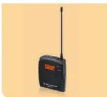
natural_image
Black wireless earphone with antenna and display screen (no visible text or symbols)
Contents
Important safety instructions ....2
The SK 100 G3 bodypack transmitter....3
The frequency bank system.... 3
Areas of application.... 4
Delivery includes....5
Product overview....6
Overview of the SK 100 G3 bodypack transmitter...... 6
Overview of the displays 7
Putting the bodypack transmitter into operation......8
Inserting the batteries/accupack....8
Charging the accupack 8
Connecting the microphone cable/instrument cable.... 8
Attaching and positioning the microphones 9
Attaching the bodypack transmitter to clothing ..... 10
Using the bodypack transmitter.... 11
Switching the bodypack transmitter on/off 11
Deactivating the lock mode temporarily.... 12
Muting the audio signal or deactivating
the RF signal.... 13
Selecting a standard display.... 15
Using the operating menu.... 16
The buttons 16
Overview of the operating menu 17
Working with the operating menu 18
Adjusting settings via the operating menu 20
The main menu "Menu" 20
The extended menu "Advanced Menu" 23
Synchronizing the bodypack transmitter
with a receiver.... 26
Synchronizing the bodypack transmitter with the receiver – individual operation ...... 26
Synchronizing bodypack transmitters with receivers – multi-channel operation ...... 26
Cleaning the bodypack transmitter 27
Recommendations and tips 28
If a problem occurs ... 29
Accessories and spare parts.... 30
Specifications.... 31
Connector assignment 32
Polar diagrams and frequency response curves of the microphones.... 33
Manufacturer Declarations.... 34
Index....36
Important safety instructions
- Read this instruction manual.
- Keep this instruction manual. Always include this instruction manual when passing the product on to third parties.
- Heed all warnings and follow all instructions in this instruction manual.
- Use only a cloth for cleaning the product.
- Do not place the product near any heat sources such as radiators, stoves, or other devices (including amplifiers) that produce heat.
- Only use attachments/accessories specified by Sennheiser.
- Refer all servicing to qualified service personnel. Servicing is required if the product has been damaged in any way, liquid has been spilled, objects have fallen inside, the product has been exposed to rain or moisture, does not operate properly or has been dropped.
- WARNING: To reduce the risk of short circuits, do not use the product near water and do not expose it to rain or moisture.
Replacement parts
When replacement parts are required, be sure the service technician uses replacement parts specified by Sennheiser or those having the same characteristics as the original part. Unauthorized substitutions may result in fire, electric shock, or other hazards.
Intended use
Intended use of the ew 100 G3 series products includes:
- having read these instructions especially the chapter "Important safety instructions",
- using the products within the operating conditions and limitations described in this instruction manual.
"Improper use" means using the products other than as described in this instruction manual, or under operating conditions which differ from those described herein.
The SK 100 G3 bodypack transmitter
This bodypack transmitter is part of the evolution wireless series generation 3 (ew G3). With this series, Sennheiser offers high-quality state-of-the-art RF transmission systems with a high level of operational reliability and ease of use. Transmitters and receivers permit wireless transmission with studio-quality sound.
Features of the evolution wireless 100 G3 series:
- Optimized PLL synthesizer and microprocessor technology
• HDX noise reduction system - Pilot tone squelch control
• True diversity technology - Switching bandwidth of 42 MHz
- Increased immunity to intermodulation and interferences in multi-channel operation
The frequency bank system
The bodypack transmitter is available in 6 UHF frequency ranges with 1,680 transmission frequencies per frequency range:
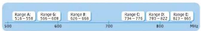
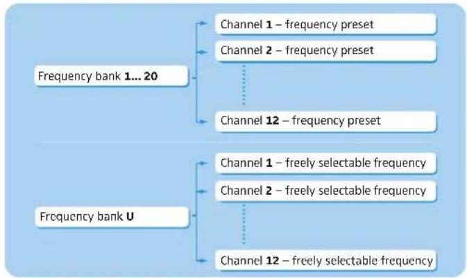
Each frequency range (A–E, G) offers 21 frequency banks with up to 12 channels each:
flowchart
graph TD
    A["Frequency bank 1... 20"] --> B["Channel 1 – frequency preset"]
    A --> C["Channel 2 – frequency preset"]
    A --> D["Channel 12 – frequency preset"]
    E["Frequency bank U"] --> F["Channel 1 – freely selectable frequency"]
    E --> G["Channel 2 – freely selectable frequency"]
    E --> H["Channel 12 – freely selectable frequency"]
Each of the channels in the frequency banks "1" to "20" has been factory-preset to a fixed frequency (frequency preset).
The factory-preset frequencies within one frequency bank are intermodulation-free. These frequencies cannot be changed.
For an overview of the frequency presets, please refer to the supplied frequency information sheet. Updated versions of the frequency information sheet can be downloaded from the SK 100 G3 product page on our website at www.sennheiser.com.
The frequency bank "U" allows you to freely select and store frequencies. It might be that these frequencies are not intermodulation-free.
Areas of application
The bodypack transmitter can be combined with the EM 100 G3 stationary receiver.
The EM 100 G3 stationary receiver is available in the same UHF frequency ranges and is equipped with the same frequency bank system with factory-preset frequencies. This has the advantage that
- a transmission system is ready for immediate use after switch-on,
- several transmission systems can be operated simultaneously on the preset frequencies without causing intermodulation interference.
Transmitter Combinable with Receiver
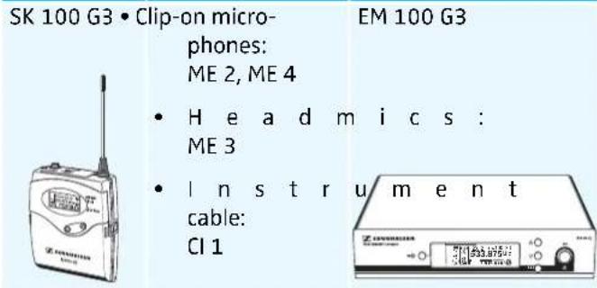
Overview of the microphones and instrument cables:
| Microphone/instrument cable | Microphonetype | Pick-up pattern |
| ME 2 clip-onmicrophone | pre-polarizedcondensermicrophone | ○ – omni |
| ME 4 clip-onmicrophone | ○ – cardioid | |
| ME 3 headmic | ○ – cardioid | |
| CI 1 instrument cable – – |
Delivery includes
The packaging contains the following items:
1 SK 100 G3 bodypack transmitter
2 AA size batteries, 1.5 V
1 instruction manual
1 frequency information sheet
1 RF licensing information sheet
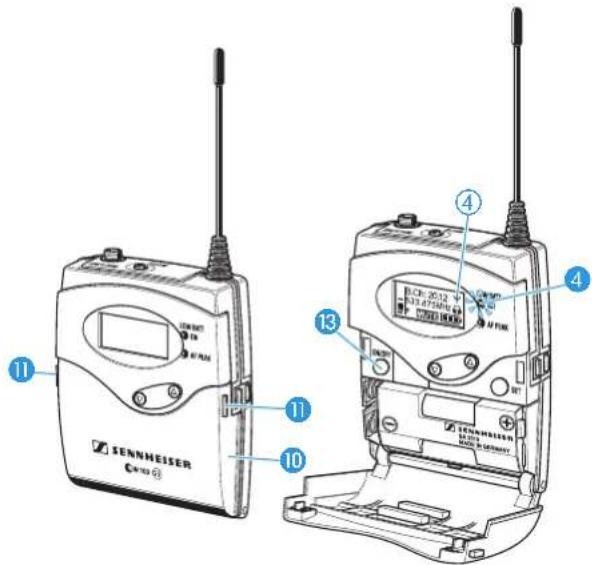
Product overview
Overview of the SK 100 G3 bodypack transmitter
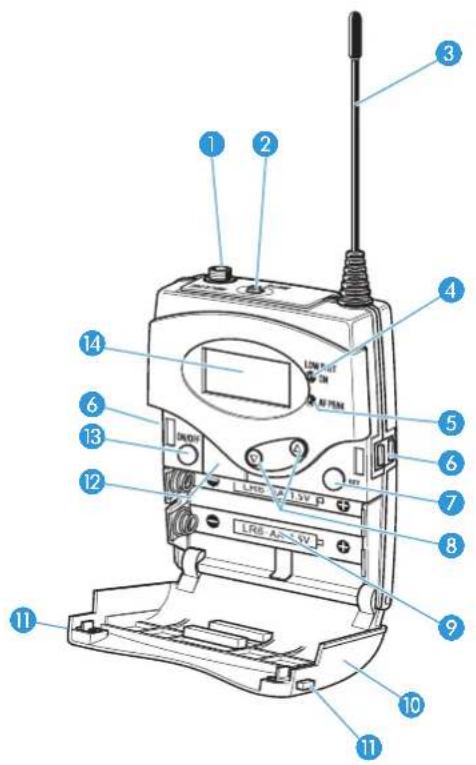
1 Microphone/instrument input (MIC/LINE), 3.5 mm jack socket, lockable
② MUTE switch
3 Antenna
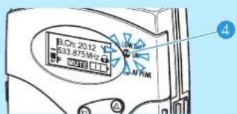
4 Operation and battery status indicator, red LED (lit = ON/flashing = LOW BATTERY)
5 Audio overmodulation indicator, yellow LED (lit = AF PEAK)
6 Charging contacts
7 SET button
8 ▲/▼ rocker button (UP/DOWN)
9 Battery compartment
10 Battery compartment cover
11 Battery compartment catches
12 Infra-red interface
13 ON/OFF button with ESC function (cancel)
14 Display panel, backlit in orange
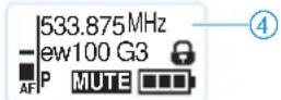
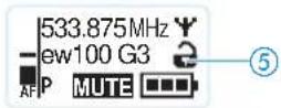
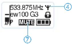
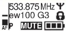
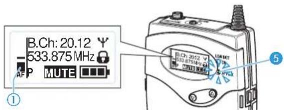
Overview of the displays
After switch-on, the bodypack transmitter displays the standard display "Frequency/Name". For further illustrations and examples of the different standard displays, refer to page 15.
The display backlighting is automatically reduced after approx. 20 seconds.
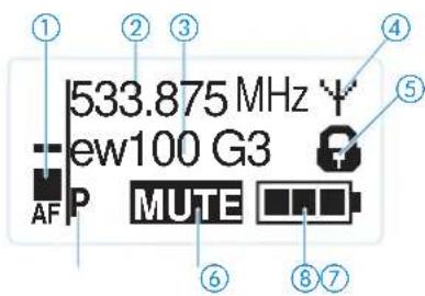
Display Meaning
① Audio level "AF"
Modulation of the bodypack transmitter with peak hold function
When the transmitter's audio input level is excessively high, the "AF" display shows full deflection and, in addition, the yellow AF PEAK LED 5 lights up:

② Frequency Current transmission frequency
③Name Freely selectable name of the transmitter
④Transmission icon RF signal is being transmitted
⑤Lock mode icon Lock mode is activated
⑥ "P" (pilot tone) Pilot tone transmission is activated
⑦"MUTE" Audio signal is muted
⑧ Battery status Charge status:


approx. 100 %
approx. 70 %
approx. 30 %
charge status is critical, the red
LOW BATTERY LED 4 is flashing:
Putting the bodypack transmitter into operation
Inserting the batteries/accupack
For powering the bodypack transmitter, you can either use two 1.5 V AA size batteries or the rechargeable Sennheiser BA 2015 accupack (see "Accessories and spare parts" on page 30).
Open the battery compartment by pushing the two catches 11 in the direction of the arrows and open the cover 10.
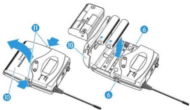
Insert the two batteries or the accupack as shown above. Please observe correct polarity when inserting the batteries/accupack.
▶ Close the battery compartment.
The battery compartment cover 10 locks into place with an audible click.
Charging the accupack
To charge the bodypack transmitter with the BA 2015 accupack (see "Accessories and spare parts" on page 30) installed:
Insert the bodypack transmitter into the L 2015 charger (see "Accessories and spare parts" on page 30).

The L 2015 charger can only charge the combination BA 2015 accupack/bodypack transmitter. Standard batteries (primary cells) or individual rechargeable battery cells cannot be charged in this way.
Connecting the microphone cable/instrument cable
The audio input is designed for the connection of both condenser microphones and instruments (e.g. guitars). DC powering of the condenser microphones is via the audio input (3.5 mm jack socket MIC/LINE 1).
Use one of the recommended Sennheiser microphones or the optional CI 1 instrument cable (see "Accessories and spare parts" on page 30).
Connect the 3.5 mm jack plug 15 from the Sennheiser microphone or instrument cable to the 3.5 mm jack socket MIC/LINE 1.
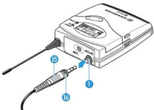
Lock the 3.5 mm jack plug by screwing down the coupling ring 16.
Via the operating menu, adjust the sensitivity of the microphone/line input (see page 20).
Attaching and positioning the microphones
ME 2
Use the microphone clip 17 to attach the microphone to clothing (e.g. tie, lapel).
▶ Attach the ME 2 microphone as close as possible to the sound source.

The ME 2 clip-on microphone has an omni-directional pick-up pattern. It is therefore not necessary to position it precisely.
ME 3
Adjust the ME 3 headmic so that a comfortable and secure fit is ensured.
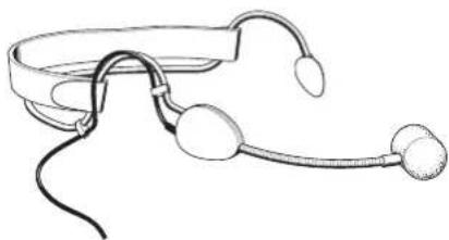
natural_image
Line drawing of a pair of earphones with earbuds and clamps (no text or symbols)The ME 3 headmic has a cardioid pick-up pattern.
▶ Position the microphone so that its sound inlet is directed towards the sound source (e.g. mouth).
ME 4
Use the microphone clip 17 to attach the microphone to clothing (e.g. tie, lapel).

The ME 4 clip-on microphone has a cardioid pick-up pattern.
▶ Position the ME 4 so that its sound inlet is directed towards the sound source (e.g. mouth).
Attaching the bodypack transmitter to clothing
You can use the belt clip 18 to attach the bodypack transmitter to clothing (e.g. belt, waistband).
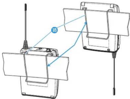
The belt clip is detachable so that you can also attach the bodypack transmitter with the antenna pointing downwards. To do so, withdraw the belt clip 18 from its fixing points and attach it the other way round.
The belt clip 18 is secured so that it cannot slide out of its fixing points accidentally.
To detach the belt clip:
▶ Lift the belt clip as shown.
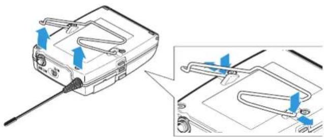
natural_image
Diagram showing a device with blue arrows indicating directional movement, alongside a close-up of its internal components (no text or symbols present)▶ Press down the belt clip at one fixing point and pull it out of the transmitter housing.
▶ Repeat for the other side.
Using the bodypack transmitter
To establish a transmission link, proceed as follows:
-
Switch the receiver on (see the instruction manual of the receiver).
-
Switch the bodypack transmitter on (see next section). The transmission link is established and the receiver's RF level display "RF" reacts.

It is vital to observe the notes on frequency selection on page 26.
If you cannot establish a transmission link between bodypack transmitter and receiver, refer to the chapter "Synchronizing the bodypack transmitter with the receiver – individual operation" on page 26.
Switching the bodypack transmitter on/off
▶ Push the two battery compartment catches 11 and open the battery compartment cover 10.
To switch the bodypack transmitter on (online operation):
ON/OFF

Briefly press the ON/OFF button 13.
The bodypack transmitter transmits an RF signal.
The standard display "Frequency/Name" appears on the display panel. The red ON LED lights up and the transmission icon is displayed.

You can switch the bodypack transmitter on and deactivate the RF signal on switch-on. For more information, see page 12.
To switch the bodypack transmitter off:
▶ If necessary, deactivate the lock mode (see page 12).
ON/OFF

Keep the ON/OFF button pressed until "OFF" appears on the display panel. The red ON LED 4 goes off and the display panel turns off.

When in the operating menu, pressing the ON/OFF button will cancel your entry (ESC function) and return you to the current standard display.
To switch the bodypack transmitter on and to deactivate the RF signal on switch-on (offline operation):
ON/OFF

Keep the ON/OFF button pressed until "RF Mute On?" appears on the display panel.

Press the SET button.
The transmission frequency is displayed but the bodypack transmitter does not transmit an RF signal. The transmission icon ④ is not displayed.

Use this function to save battery power or to prepare a bodypack transmitter for use during live operation without causing interference to existing transmission links.
To activate the RF signal:
ON/OFF

▶ Briefly press the ON/OFF button. "RF Mute Off?" appears on the display panel.

▶ Press the SET button. The transmission icon ④ is displayed again.
Deactivating the lock mode temporarily
You can activate or deactivate the automatic lock mode via the "Auto Lock" menu item (see page 22).
If the lock mode is activated, you have to temporarily deactivate it in order to be able to operate the bodypack transmitter:

Press the SET button. "Locked" appears on the display panel.
▼ △
▶ Press the rocker button. "Unlock?" appears on the display panel.

▶ Press the SET button.
The lock mode is temporarily deactivated.
How you are using the bodypack transmitter determines how long the lock mode remains deactivated:
When you are in the operating menu
The lock mode remains deactivated until you exit the operating menu.
When one of the standard displays is shown
The lock mode is automatically activated after 10 seconds.
The lock mode icon ⑤ flashes prior to the lock mode being activated again.
Muting the audio signal or deactivating the RF signal
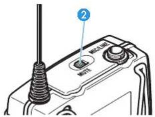
The MUTE switch ② allows you to mute the audio signal or to deactivate the RF signal.
Via the "Mute Mode" menu item, you can set the desired function of the MUTE switch ② (see page 24):
| Setting | Slide the MUTE switch 2 ... | Function |
| "AF On/Off" ... | to the left (position MUTE) | Mutes the audio signal |
| ... to the right Unmutes the audio signal | ||
| "RF On/Off" ... | to the left (position MUTE) | Deactivates the RF signal (offline operation) |
| ... to the right Activates the RF signal (online operation) | ||
"Disabled" No function
From the "Mute Mode" menu item, select the desired setting (see page 24).
Exit the operating menu.
Slide the MUTE switch MUTE 2 to the left, to the position MUTE.
The bodypack transmitter reacts as indicated in the table.
The current state of the muting function or the RF signal is displayed on the display panel of the bodypack transmitter.
Audio signal is muted
Transmitter's display panel: "MUTE" ⑦ is displayed
Audio signal is activated (muting is deactivated)
Transmitter's display panel: "MUTE" ⑦ is not displayed
RF signal is deactivated
Transmitter's display panel: transmission icon ④ is not displayed, "MUTE" ⑦ is displayed
RF signal is activated
Transmitter's display panel: Transmission icon ④ is displayed, "MUTE" ⑦ is not displayed

You can also deactivate the RF signal on switch-on. For more information, refer to the chapter "Switching the bodypack transmitter on/off" on page 12.
Using the ON/OFF button, you can also activate/deactivate the RF signal during operation.
To do so, briefly press the ON/OFF button and proceed as described on page 12.
Selecting a standard display

▶ Press the rocker button to select a standard display:
| Contents of the display | Selectable standard display |
 | “Frequency/Name” |
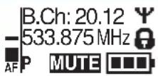 | “Frequency bank/Channel/Frequency” |
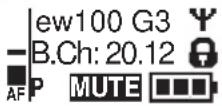 | “Name/Frequency bank/Channel” |
Using the operating menu
A special feature of the Sennheiser ew G3 series is the consistent, intuitive menu structure of transmitters and receivers. As a result, adjustments to the settings can be made quickly – even in stressful situations, for example on stage or during a live show or presentation.


Make use of the possibility to adjust settings via the operating menu of the receiver and to transfer these settings to the bodypack transmitter.
For more information on how to transfer settings to the bodypack transmitter, refer to the instruction manual of your receiver. The relevant information is marked with the sync icon.
The buttons
| Button Function of the button | |
| Press the ON/OFF buttonON/OFF[3HYC] | Switches the bodypack transmitter on and offCancels the entry and returns to the current standard display (ESC function)Activates/deactivates the RF signal (special function, see page 12) |
Press the SET button | Changes from the current standard display to the operating menuCalls up a menu itemEnters a submenuStores the settings and returns to the operating menu |
| Press the rocker button[K200] | Selects a standard displayChanges to the next/previous menu itemChanges the setting of a menu item |
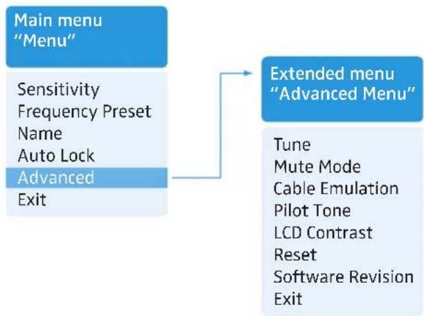
Overview of the operating menu
flowchart
graph TD
    A["Main menu "Menu""] --> B["Extended menu "Advanced Menu""]
    A --> C["Sensitivity\nFrequency Preset\nName\nAuto Lock\nAdvanced\nExit"]
    B --> D["Tune\nMute Mode\nCable Emulation\nPilot Tone\nLCD Contrast\nReset\nSoftware Revision\nExit"]
Display Function of the menu item
| Main menu “Menu” | |
| Sensitivity | Adjusts the sensitivity “AF”(see page 20) |
| Frequency Preset | Sets the frequency bank and the channel (see page 21) |
| Name Enters the transmitter name(see page 22) | |
| Auto Lock Activates/deactivates the lock mode(see page 22) | |
| Advanced Calls up | the extended menu“Advanced Menu” (see page 23) |
| Exit Exits the operating menu and returnsto the current standard display | |
| Extended menu “Advanced Menu” | |
| Tune Sets the transmission frequencies forthe frequency bank “U” (see page 23)Sets the channel and the transmissionfrequency for the frequency bank “U”(see page 23) | |
| Mute Mode | Sets the mode for the MUTE switch(see page 24) |
| Cable Emulation | Emulates guitar cable capacities(see page 24) |
| Pilot Tone | Activates/deactivates the pilot tonetransmission (see page 24) |
| LCD Contrast | Adjusts the contrast of the displaypanel (see page 25) |
| Reset Resets the settings made in theoperating menu (see page 25) | |
| Software Revision | Displays the current software revision(see page 25) |
| Exit Exits the extended menu “AdvancedMenu” and returns to the main menu | |
Working with the operating menu

If the lock mode is activated, you have to deactivate it In order to be able to work with the operating menu (see page 12).
By way of example of the "Sensitivity" menu, this section describes how to use the operating menu.
Changing from a standard display to the operating menu

▶ Press the SET button. The current standard display is replaced by the main menu. The last selected menu item is displayed.
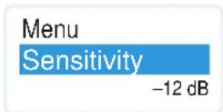
Selecting a menu item

▶Press the rocker button to change to the "Sensitivity" menu item. The current setting of the selected menu item is displayed:
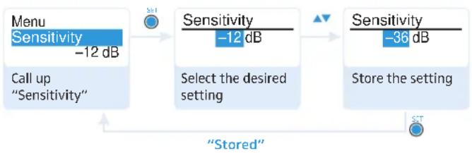
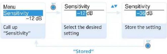
Changing and storing settings
flowchart
graph LR
    A["Menu Sensitivity -12 dB"] --> B["Sensitivity -12 dB"]
    B --> C["Select the desired setting"]
    C --> D["Sensitivity -36 dB"]
    D --> E["Store the setting"]
    F["Stored"] --> A
    F --> B
    F --> C
    F --> E

▶ Press the SET button to call up the menu item.

▶Press the rocker button to adjust the input sensitivity.

▶ Press the SET button to store the setting.
Canceling an entry

▶ Press the ON/OFF button to cancel the entry. The current standard display appears on the display panel.

To subsequently return to the last edited menu item:

▶ Press the SET button repeatedly until the last edited menu item appears.
Exiting a menu item

Change to the "Exit" menu item.


▶ Confirm your selection. You return to the next higher menu level.
To directly return to the current standard display:

▶ Press the ON/OFF button.
Adjusting settings via the operating menu

Make use of the possibility to adjust settings via the operating menu of your receiver and to these settings to the bodypack transmitter.

For more information, refer to the instruction manual of the receiver. The relevant information is marked with the sync icon.
The main menu "Menu"
Adjusting the input sensitivity – "Sensitivity"
flowchart
graph LR
    A["Menu Sensitivity"] --> B["Sensitivity"]
    B --> C["Select the desired setting"]
    C --> D["Sensitivity"]
    D --> E["Store the setting"]
    style A fill:#f9f,stroke:#333
    style B fill:#ccf,stroke:#333
    style C fill:#cfc,stroke:#333
    style D fill:#fcc,stroke:#333
    style E fill:#cff,stroke:#333
Adjustment range: 0 to -60 dB, adjustable in steps of 3 dB

The audio level display "AF" ① always indicates the audio level, even if the bodypack transmitter is muted, e.g. allowing you to check the adjusted sensitivity before live operation.
| Input sensitivity is adjusted ... | Effect/display |
| ... too high Close talking distances, speakers with loud voices or loud music passages cause overmodulation in the transmission link. The yellow AF PEAK LED 5 lights up. The audio level display “AF” 1 shows full deflection for the duration of the overmodulation. | |
| ... correctly | The audio level display “AF” 1 shows full deflection only during the loudest passages. |
| ... too low The transmission link is undermodulated. This results in a signal with high background noise. | |
The following figures are a guide to the best settings:
| Transmission situation Sensitivity setting | |
| Loud music/vocals | -30 to -21 dB |
| Presentations -21 to 0 dB | |
| Instrument input | |
| Electric guitars with single coil pickups | -30 to -24 dB |
| Electric guitars with humbucker pickups | -45 to -30 dB |
| Guitars with active electronics (active pickups, active EQs, piezo pickups) | -45 to -30 dB |
Selecting the frequency bank and the channel manually – "Frequency Preset"
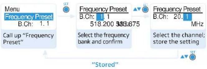
flowchart
graph TD
    A["Menu\nFrequency Preset\nB.Ch: 1.1\nCall up "Frequency Preset""] --> B["Select the frequency bank and confirm"]
    B --> C["Frequency Preset\nB.Ch: 1.1\n518.200 MHz\nSelect the channel; store the setting"]
    C --> D["Frequency Preset\nB.Ch: 20.1\nMHz"]
    D --> E["Stored"]
    E --> A

When you are in the "Frequency Preset" menu item, the RF signal is deactivated.
Overview of the frequency banks and channels:
| Frequency bank | Channels Type | |
| “1” to “20” | up to 12 per frequency bank | System bank: frequencies are factory-preset |
| “U” up to 12 | User bank: | frequencies are freely selectable |

When setting up multi-channel systems, please observe the following:
Only the factory-preset frequencies within one frequency bank are intermodulation-free (see page 26).
Bodypack transmitter and receiver of a transmission link have to be set to the same frequency.
It is vital to observe the notes on frequency selection on page 26.
Entering a name – "Name"
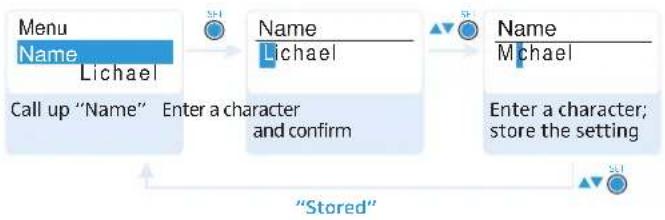
flowchart
graph TD
    A["Menu\nName\nLichael\nCall up "Name""] --> B["Name\nLichael\nEnter a character and confirm"]
    B --> C["Name\nMichael\nEnter a character; store the setting"]
    C --> D["Stored"]
    D --> A
Via the "Name" menu, you can enter a freely selectable name (e.g. the name of the performer) for the bodypack transmitter.
The name can be displayed on the standard displays "Frequency/Name" and "Name/Frequency bank/Channel". The name can consist of up to 8 characters such as:
- letters (without pronunciation marks),
- numbers from 0 to 9,
• special characters and spaces.
To enter a name, proceed as follows:
▼▲ ▶Press the rocker button to select a character.

Press the SET button to change to the next segment/character or to store the complete entry.
Activating/deactivating the automatic lock mode – "Auto Lock"
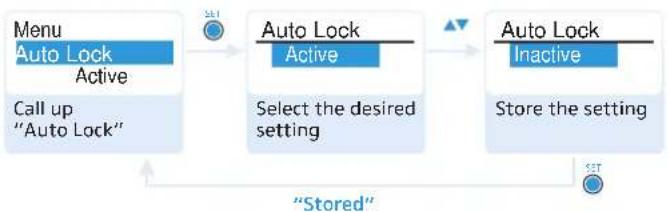
flowchart
graph LR
    A["Menu\nAuto Lock\nActive\nCall up\n"Auto Lock""] --> B["Auto Lock\nActive\nSelect the desired setting"]
    B --> C["Auto Lock\nInactive\nStore the setting"]
    C --> D["Stored"]
    D --> A
The lock mode prevents that the bodypack transmitter is accidentally switched off or programmed during operation. The lock mode icon ⑤ 🎨 on the current standard display indicates that the lock mode is activated.
Press the rocker button to select the desired setting.
For information on how to use the lock mode, refer to page 12.
The extended menu "Advanced Menu"
Setting transmission frequencies for the frequency bank "U" – "Tune"

When you have selected one of the system banks and then select the "Tune" menu, the bodypack transmitter automatically switches to channel 1 of the frequency bank "U". In this case, "U.1" briefly appears on the display panel.
Upon delivery, the channels of the frequency bank "U" are not assigned a transmission frequency.
When you are in the "Tune" menu item, the RF signal is deactivated.
Via the "Tune" menu item, you can set a transmission frequency to be stored in the current channel or you can select a different channel in the frequency bank "U" and assign this channel a transmission frequency.

It is vital to observe the notes on frequency selection on page 26.
Setting a transmission frequency for the current channel

Press the rocker button until the "Tune" menu item appears.

▶ Press the SET button. The frequency selection appears.
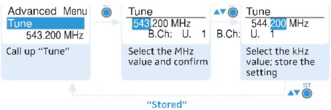
▶ Set the desired frequency.

▶ Press the SET button. Your settings are stored. You are back to the operating menu.
Selecting a channel and assigning this channel a frequency

Press the rocker button until the "Tune" menu item appears.

Keep the SET button pressed until the channel selection appears.
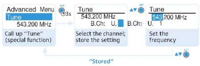
▶ Set the desired channel.

▶ Press the SET button. The frequency selection appears.
▶ Set the desired frequency.

▶Press the SET button. Your settings are stored. You are back to the operating menu.
Setting the mode for the MUTE switch – "Mute Mode"
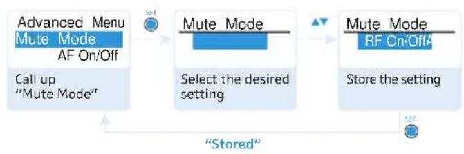
flowchart
graph LR
    A["Advanced Menu\nMute Mode\nAF On/Off\nCall up\n"Mute Mode""] --> B["Mute Mode\nSelect the desired setting"]
    B --> C["Mute Mode\nRF On/Off\nStore the setting"]
    C --> D["Stored"]
| Mode Function | |
| "AF On/Off" | When the switch is in the MUTE posi- tion, no audio signal is transmitted. |
| "RF On/Off" | When the switch is in the MUTE posi- tion, the RF signal is deactivated. |
| "Disabled" The muting function is deactivated. | |
For information on how to use the MUTE switch, refer to page 13.
Emulating guitar cables – "Cable Emulation"
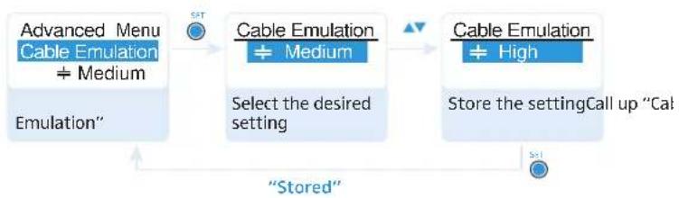
flowchart
graph LR
    A["Advanced Menu\nCable Emulation\n÷ Medium\nEmulation""] --> B["Cable Emulation\n÷ Medium"]
    B --> C["Cable Emulation\n÷ High\nStore the settingCall up "Cal""]
    C --> D["Stored"]
    D --> A
Via the "Cable Emulation" menu item, you can emulate 4 different guitar cable capacities.
Activating/deactivating the pilot tone transmission – "Pilot Tone"
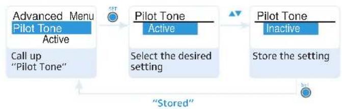
flowchart
graph LR
    A["Advanced Menu\nPilot Tone\nActive\nCall up\n"Pilot Tone""] --> B["Pilot Tone\nActive\nSelect the desired setting"]
    B --> C["Pilot Tone\nInactive\nStore the setting"]
    C --> D["Stored"]
    D --> A
The bodypack transmitter adds an inaudible signal, known as the pilot tone, to the transmitted signal. The receiver detects and evaluates the pilot tone.
The pilot tone supports the receiver's squelch function (Squelch) and protects against interference due to RF signals from other devices.
Devices of the ew 100 G1 series (generation 1) do not support the pilot tone function. Therefore, please observe the following when combining a bodypack transmitter or receiver of the ew 100 G3 series (generation 3) with devices from an earlier evolution wireless generation:
| Transmitter Receiver Make sure to ... | |
| ew G3 / w G2 w G3 / w G2e.. activate the pilot | tone function on both bodypack transmitter and receiver. |
| ew G3 w G1 ... deactivate the pilot | tone function on the ew 100 G3 bodypack transmitter. |
| ew G1 w G3 ... deactivate the pilot | tone function on the ew 100 G3 receiver. |
Adjusting the contrast of the display panel – "LCD Contrast"
You can adjust the contrast of the display panel in 16 steps.
Resetting the settings made in the operating menu – "Reset"
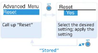
flowchart
graph TD
    A["Advanced Menu Reset"] --> B["Call up "Reset""]
    C["Reset"] --> D["Select the desired setting; apply the setting"]
    D --> E["Stored"]
    E --> A
    style A fill:#cce5ff,stroke:#333
    style C fill:#cce5ff,stroke:#333
    style B fill:#cce5ff,stroke:#333
    style D fill:#cce5ff,stroke:#333
    style E fill:#cce5ff,stroke:#333
When resetting the settings made in the operating menu, only the selected settings for the pilot tone and for the frequency bank "U" remain unchanged. For an overview of the factory-preset default settings, refer to the supplied frequency information sheet.
Displaying the software revision – "Software Revision"
You can display the current software revision of the body-pack transmitter.
Synchronizing the bodypack transmitter with a receiver
When synchronizing the bodypack transmitter with a receiver, please observe the following:

Only use a transmitter and a receiver from the same frequency range (see the type plate on the transmitter and the receiver).
Make sure that the desired frequencies are listed in the enclosed frequency information sheet.
Make sure that the desired frequencies are approved and legal in your country and, if necessary, apply for an operating license.
Synchronizing the bodypack transmitter with the receiver – individual operation
Upon delivery, the bodypack transmitter and the receiver are synchronized with each other.
If, however, you cannot establish a transmission link between bodypack transmitter and receiver, you have to synchronize the channels of the devices.
For information on automatic synchronization of the body-pack transmitter with the receiver (individual operation), refer to the instruction manual of the receiver. This information is marked with the sjon.
Alternatively, you can set the channel on the bodypack transmitter manually:
Make sure that you set the bodypack transmitter to the same frequency bank and the same channel as the receiver (see page 21).
If you still cannot establish a transmission link, refer to the chapter "If a problem occurs ..." on page 29.
Synchronizing bodypack transmitters with receivers – multi-channel operation
Combined with ew 100 G3 receivers, ew 100 G3 bodypack transmitters can form transmission links that can be used in multi-channel systems.
For information on automatic synchronization of bodypack transmitters with receivers (multi-channel operation), refer to the instruction manual of your receiver.
For more information on multi-channel operation, visit the SK 100 G3 product page at www.sennheiser.com.
Cleaning the bodypack transmitter
CAUTION! Liquids can damage the electronics of the bodypack transmitter!
Liquids entering the housing of the device can cause a short-circuit and damage the electronics.
▶ Keep all liquids away from the bodypack transmitter.
▶ Use a cloth to clean the bodypack transmitter from time to time.
▶ Do not use any solvents or cleansing agents.
Recommendations and tips
... for the ME 2 and ME 4 clip-on microphones
- To reduce level variations to a minimum when the user turns his or her head away from the microphone, attach the microphone as centrally as possible.
- To protect the microphone against excessive sweat/moisture, avoid direct skin contact.
- Attach the microphone carefully and conduct the cable so that noise due to friction is avoided.
- Always use the ME 4 directional microphone with a windshield and direct the microphone towards the sound source (e.g. mouth).
... for the ME 3 headmic
- Always use the microphone with a pop shield and position the microphone at the corner of the mouth.
- You can vary the bass reproduction by increasing/decreasing the talking distance.
- Make sure that the sound inlet is directed towards the mouth. The sound inlet is marked with a little dot.
... for the bodypack transmitter
- Make sure that the antenna and the microphone cable do not cross.
- The antenna should hang freely and be at least 1 cm away from the body. The antenna must not be in direct contact with the skin.
- For best results, make sure that the transmitter sensitivity is correctly adjusted.
... for optimum reception
- Transmission range depends to a large extent on location and can vary from about 10 m to about 150 m. There should be a "free line of sight" between transmitting and receiving antennas.
- To avoid overloading the receiver, observe a minimum distance of 5 m between transmitting and receiving antennas.
... for multi-channel operation
- For multi-channel operation, you should only use the channels within one frequency bank. Each of the frequency banks "1" to "20" accommodates factory-preset frequencies which are intermodulation-free.
- When using several transmitters simultaneously, interference can be avoided by maintaining a minimum distance of 20cm between two transmitters.
If a problem occurs ...
| Problem Possible cause Possible solution | ||
| Bodypack transmitter cannot be operated, "Locked" appears on the display panel | Lock mode is activated | Deactivate the lock mode (see page 12). |
| No operation indication | Batteries are flat or accupack is flat | Replace the batteries or recharge the accupack (see page 8). |
| No RF signal at the receiver | Bodypack transmitter and receiver are not on the same channel | Set the bodypack transmitter to the same channel as the receiver. Synchronize the body-pack transmitter with the receiver (see page 26). |
| Transmission range is exceeded | Reduce the distance between bodypack transmitter and receiving antennas. | |
| RF signal is deactivated ("RF Mute") | Activate the RF signal (see page 13). | |
| RF signal available, no audio signal, "MUTE" appears on the display panel | Bodypack transmitter is muted (MUTE) | Cancel the muting (see page 13). |
| Receiver's squelch threshold is adjusted too high | Reduce the squelch threshold setting on the receiver. | |
| Bodypack transmitter doesn't transmit a pilot tone | Activate or deactivate the pilot tone transmission (see page 24). | |
| Audio signal has a high level of background noise or audio signal is distorted | Bodypack transmitter's sensitivity is adjusted too low/too high | Adjust the input sensitivity (see page 20). |
If a problem occurs that is not listed in the above table or if the problem cannot be solved with the proposed solutions, please contact your local Sennheiser partner for assistance.
To find a Sennheiser partner in your country, search at www.sennheiser.com under "Service & Support".
Accessories and spare parts
The following accessories are available from your specialist dealer:
Cat. No. Product name and description
009950 BA 2015 accupack
009828 L 2015 charger
503168 CC 3 system case
009825 BPP 1 bodypack pouch
Adapters
009827 DC 2 power adapter (12 V DC)
Cables
005021 CI 1 instrument cable (with 14 " (6.3 mm) jack plug)
004840 CL 2 line cable (with XLR-3F connector)
Microphones
005018 ME 2 clip-on microphone, condenser, omni-directional
005020 ME 4 clip-on microphone, condenser, cardioid
009862 HSP 2 headmic, condenser, omni-directional
009864 HSP 4 headmic, condenser, cardioid
005019 ME 3-ew headmic, condenser, cardioid
009831 MKE 2-ew Gold clip-on microphone, color black condenser, omni-directional
009832 MKE 2-ew-3 clip-on microphone, color beige condenser, omni-directional
500527 MKE 40 clip-on microphone, condenser, cardioid
Specifications
RF characteristics
Modulation wideband FM
Frequency ranges 516–558, 566–608,
626-668, 734-776,
780-822, 823-865 MHz
(A-E, G, see page 3)
Transmission frequencies 1,680
frequencies, tune- able in steps of 25 kHz
20 frequency banks, each with up to 12 factory-preset channels
1 frequency bank with up to 12 user programmable channels
Switching bandwidth 42 MHz
Nominal/peak deviation ±24 kHz/±48 kHz
Frequency stability ≤ ±15 ppm
RF output power at 50 Ω typ. 30 mW
Pilot tone squelch can be switched off
AF characteristics
Compander system Sennheiser HDX
AF frequency response microphone:
80–18,000 Hz
line: 25–18,000 Hz
Signal-to-noise ratio
(1 mV, peak deviation) ≥ 110 dBA
THD ≤ 0.9%
Max. input voltage
microphone/line
3 V _rms
Input impedance
microphone/line
40 kΩ, unbalanced/1 MΩ
Input capacitance
switchable
Adjustment range of input
sensitivity
60 dB, adjustable
in 3-dB steps
Overall device
Temperature range
-10^ to +55^
Power supply
2 AA size batteries, 1.5 V or BA 2015 accupack
Nominal voltage
2.4 V ---
Current consumption:
at nominal voltage typ. 180 mA (30 mW)
with switched-off
transmitter
≤ 25 μA
Operating time typ. 8 hrs
Dimensions approx. 82 x 64 x 24 mm
Weight (incl. batteries) approx. 160 g
In compliance with
| Europe | EMC | EN | 301489-1/-9 |
| CE | Radio | EN | 300422-1/-2 |
| Safety | EN | 60065 | |
| EN 62311 (SAR) | |||
Approved by
| Canada Industry Canada RSS 123 | |
| IC 2099A-G3SK | |
| limited to 806 MHz | |
USA FCC-Part 74
FCC-ID: DMO G3SK
limited to 698 MHz
Microphones
| ME 2 ME 3 ME 4 | |||
| Microphone type condenser condenser condenser | |||
| Sensitivity | 20 mV/Pa | 1.6 mV/Pa | 40 mV/Pa |
| Pick-up pattern omni cardioid | cardioid | ||
| Max. SPL | 130 dB SPL | 150 dB SPL | 120 dB SPL |
Connector assignment
3.5 mm jack plug:
| Mic | Line |
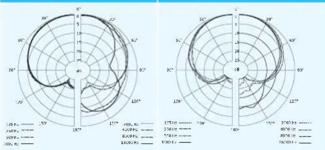
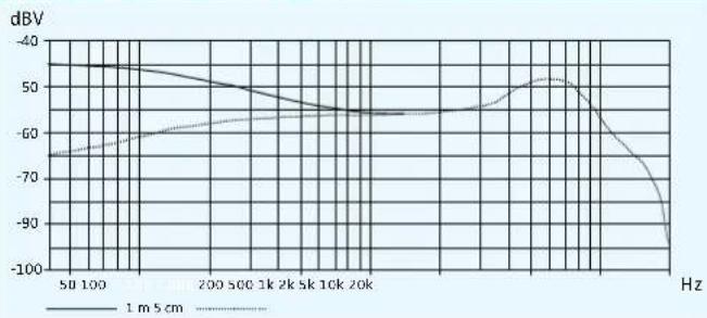
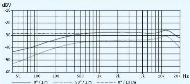
Polar diagrams and frequency response curves of the microphones
Polar diagram ME 3 Polar diagram ME 4
radar
| Angle | Pressure (kPa) | |---|---| | 0° | 450 | | 30° | 520 | | 60° | 480 | | 90° | 420 | | 120° | 380 | | 150° | 350 | | 180° | 320 | | 210° | 300 | | 240° | 310 | | 270° | 330 | | 300° | 360 | | 330° | 390 | | 360° | 410 |Frequency response curve ME 2
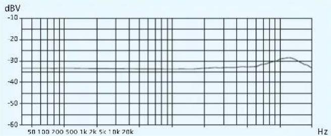
line
| Frequency | dBV | | --------- | ---- | | 50 | -35 | | 100 | -35 | | 200 | -35 | | 500 | -35 | | 1k | -35 | | 2k | -35 | | 5k | -35 | | 10k | -35 | | 20k | -35 |Frequency response curve ME 3
line
| Frequency | 1 m 5 cm | Other | | --------- | -------- | ----- | | 100 | -40 | -60 | | 200 S00 | -50 | -55 | | 1k | -55 | -50 | | 2k | -58 | -48 | | Sk | -60 | -45 | | 10k | -65 | -40 | | 20k | -70 | -35 | | 1000 | -90 | -100 |Frequency response curve ME 4
line
| Hz | 0° / 1 m | 90° / 1 m | 0° / 10 cm | |------|----------|-----------|------------| | 50 | -45 | -55 | -30 | | 100 | -40 | -45 | -30 | | 200 | -35 | -40 | -30 | | 500 | -30 | -35 | -30 | | 1k | -28 | -32 | -30 | | 2k | -27 | -31 | -30 | | 5k | -26 | -30 | -30 | | 10k | -25 | -29 | -30 | | 20k | -28 | -35 | -30 |Manufacturer Declarations
Warranty
Sennheiser electronic GmbH & Co. KG gives a warranty of 24 months on this product.
For the current warranty conditions, please visit our web site at www.sennheiser.com or contact your Sennheiser partner.
In compliance with the following requirements
• RoHS Directive (2002/95/EC)
• WEEE Directive (2002/96/EC)

Please dispose of the bodypack transmitter at the end of its operational lifetime by taking it to your local collection point or recycling center for such equipment.
• Battery Directive (2006/66/EC)

The supplied batteries or rechargeable batteries can be recycled. Please dispose of them as special waste or return them to your specialist dealer. In order to protect the environment, only dispose of exhausted batteries.
CE Declaration of Conformity
CE 0682①
- R&TTE Directive (1999/5/CE) The declaration is available at www.sennheiser.com. Before putting the device into operation, please observe the respective country-specific regulations.
Statements regarding FCC and Industry Canada
This device complies with Part 15 of the FCC Rules and with RSS-210 of Industry Canada. Operation is subject to the following two conditions: (1) this device may not cause harmful interference, and (2) this device must accept any interference received, including interference that may cause undesired operation.
This equipment has been tested and found to comply with the limits for a Class B digital device, pursuant to Part 15 of the FCC Rules. These limits are designed to provide reasonable protection against harmful interference in a residential installation. This equipment generates, uses and can radiate radio frequency energy and, if not installed and used in accordance with the instructions, may cause harmful interference to radio communications. However, there is no guarantee that interference will not occur in a particular installation. If this equipment does cause harmful interference to radio or television reception, which can be determined by turning the equipment off and on, the user is encouraged to try to correct the interference by one or more of the following measures:
- Reorient or relocate the receiving antenna.
- Increase the separation between the equipment and receiver.
- Connect the equipment into an outlet on a circuit different from that to which the receiver is connected.
- Consult the dealer or an experienced radio/TV technician for help.
This class B digital device complies with the Canadian ICES-003.
Changes or modifications made to this equipment not expressly approved by Sennheiser electronic Corp. may void the FCC authorization to operate this equipment.
Before putting the device into operation, please observe the respective country-specific regulations!
Index
Accupack
charging 8
inserting 8
Activating/deactivating
lock mode (Auto Lock) 22
pilot tone 24
Adjusting
cable emulation 24
contrast (LCD Contrast) 25
input sensitivity (Sensitivity) 20
Advanced Menu (extended menu)
overview 17
settings 23
AF (audio level) 7
AF PEAK (overmodulation) 7
Attaching
bodypack transmitter 10
microphones 9
Audio signal, muting (Mute) 13
Auto Lock (activating/deactivating the lock mode) 22
Batteries, inserting 8
Bodypack transmitter
attaching to clothing 10
cleaning 27
resetting (Reset) 25
switching on/off 11
synchronizing with receiver 26
Buttons (function of the \~) 16
Cable emulation (emulating guitar cables) 24
Channel
assigning a frequency 23
overview 3
selecting (Frequency Preset) 21
selecting (Tune) 23
Charging
accupack 8
battery status display 7
Cleaning (bodypack transmitter) 27
Connecting (microphone/instrument cable) 8
Deactivating
lock mode temporarily 12
Displays
adjusting the contrast (LCD Contrast) 25
charge status 7
overview 7
standard displays 15
Emulating guitar cables (Cable emulation) 24
Factory default settings (resetting the settings in the operating menu) 25
Frequency
preset frequencies 3
\~ ranges 3
selecting \~ presets 21
setting the transmission \~ 23
Frequency bank
overview 3
selecting (Frequency Preset) 21
\~ system 3
Frequency Preset (selecting a frequency bank/channel) 21
Infra-red transmission 26
Inserting (batteries/accupack) 8
Instrument cable, connecting 8
LCD Contrast (contrast of the display panel) 25
Lock mode
activating/deactivating (Auto Lock) 22
deactivating temporarily 12
Locked (lock mode activated) 12
Menu (main menu)
overview 17
settings 20
Microphones
attaching/positioning 9
connecting the microphone cable 8
overview 4
pick-up patterns 4
polar diagrams and frequency response curves 33
suitable \~ 4
Modulation (input sensitivity/adjusting the
sensitivity) 20
Multi-channel system 26
Mute (muting the audio signal) 13
Mute Mode (setting the mode for the MUTE switch) 24
MUTE switch
function 13
setting the mode (Mute Mode) 24
Muting (audio signal) 13
Name (entering a name) 22
Offline operation (RF signal deactivated) 12
Online operation (RF signal activated) 11
Pilot tone
activating/deactivating 24
transmission 24
Reset (resetting the settings in the operating menu) 25
RF signal
activating (online operation) 11
deactivating (during operation) 14
deactivating (offline operation) 12, 13
Sensitivity (adjusting the input sensitivity) 20
Setting
MUTE switch (Mute Mode) 24
transmission frequency (Tune) 23
Setting up
transmission link 26
Software Revision (displaying the software revision) 25
Switching on/off
bodypack transmitter 11
Synchronizing (bodypack transmitter/receiver) 26
Transmission frequency
selecting (Frequency Preset) 21
setting (Tune) 23
Transmission power, optimizing 28
Troubleshooting 29
Tune (setting a transmission frequency) 23
Unlock (deactivating the lock mode) 12
Using
bodypack transmitter 11
operating menu 18
Sennheiser electronic GmbH & Co. KG Am Labor 1, 30900 Wedemark, Germany www.sennheiser.com
Printed in Germany Publ. 01/09 529669/A01