 — Automotive — Mode d'emploi PDF")
Golf GTI (2001) - Automotive VOLKSWAGEN - Free user manual and instructions
Find the device manual for free Golf GTI (2001) VOLKSWAGEN in PDF.

| Product Type | Automobile |
| Brand | Volkswagen |
| Model | Golf GTI (2001) |
| Engine Code | BDF |
| Engine Type | 2.8L VR6 4V (24-Valve) |
| Displacement | 2.8 L (2792 cc) |
| Power Output | 147 kW (200 hp) at 6200 rpm |
| Torque | 265 Nm at 3200 rpm |
| Fuel System | Motronic ME7.1.1, sequential fuel injection |
| Ignition System | Static high-tension distribution with six ignition coils |
| Fuel Type | Unleaded gasoline (RON 98 recommended, RON 91/95 permissible) |
| Transmission | 5-speed manual or 5-speed automatic (09A) |
| Exhaust Emission Level | LEV (Low Emission Vehicle) |
| On-Board Diagnostic | OBD II |
| Compression Ratio | 10.5:1 |
| Firing Order | 1-5-3-6-2-4 |
| Spark Plug Type | VW PZF R5D-11, electrode gap max. 1.1 mm |
| Engine Oil | SAE 5W-30 or 5W-40, VW 502 00 or 505 00 |
| Cooling System | Water-cooled with thermostat, coolant capacity approx. 8.5 L |
| Length | 4148 mm |
| Width | 1735 mm |
| Height | 1440 mm |
| Wheelbase | 2512 mm |
| Curb Weight | Approx. 1250 kg |
| Fuel Tank Capacity | 55 L |
Frequently Asked Questions - Golf GTI (2001) VOLKSWAGEN
User questions about Golf GTI (2001) VOLKSWAGEN
0 question about this device. Answer the ones you know or ask your own.
Ask a new question about this device
Download the instructions for your Automotive in PDF format for free! Find your manual Golf GTI (2001) - VOLKSWAGEN and take your electronic device back in hand. On this page are published all the documents necessary for the use of your device. Golf GTI (2001) by VOLKSWAGEN.
USER MANUAL Golf GTI (2001) VOLKSWAGEN
1.8L turbo, 1.9L TDI and PD diesel
2.0L gasoline, 2.8L VR6

natural_image
Side profile illustration of a silver sedan against a red background (no text or symbols)
natural_image
Side profile of a silver sedan against a red background (no text or symbols visible)Volkswagen
Audi
BMW

natural_image
Side view of a black sedan car (no visible text or symbols)Golf,
GTI,
Jetta 1999-2004,
Jetta Wagon 2001-2004,
R32
Subscription expires 2005 Feb 13

natural_image
Front view of a silver sedan car (no visible text or symbols)Golf,
GTI,
Jetta 1993-1999,
Cabrio 1995-2002

Click here to purchase
natural_image
Front view of a black sedan car (no visible text or symbols)Passat,
Passat Wagon 1995-1997

Click here to purchase
natural_image
Side view of a silver sedan car (no visible text or symbols)Passat,
Passat Wagon 1998-2004

Click here to purchase
natural_image
Side view of a modern compact car (no visible text or symbols)New Beetle 1998-2004,
New Beetle Convertible 2004

Click here to purchase

natural_image
Side view of a silver minivan (no visible text or symbols)Eurovan 1992-2004

Click here to purchase
natural_image
Side profile of a silver SUV (no visible text or symbols)Touareg

Click here to purchase

natural_image
Side view of a black sedan car (no visible text or symbols)Phaeton

Click here to purchase
Select a topic
00 - General, Technical data
10 - Engine - Assembly
13 - Engine - Crankshaft, Cylinder block
15 - Engine - Cylinder head, Valvetrain
17 - Engine - Lubrication
19 - Engine - Cooling system
20 - Fuel Supply
26 - Exhaust system, Emission controls
Additional Information
System Overviews
Other Topics
24-Valve VR6 Variable Camshaft Timing Operation
Technical data
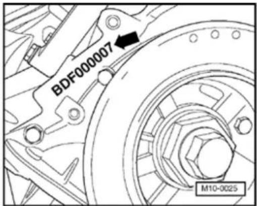
Engine number
The engine number (engine code and serial number) are located next to the vibration damper on the cylinder block.
The engine number consists of up to nine characters (alphanumeric). The first part (maximal 3 characters) makes up the engine code and the second part (6 characters), the serial number. If more than 999,999 engines with the same engine code are produced, the first of the six characters is replaced with a letter.
Additionally there is a sticker on the intake manifold with the engine code and serial number.
The engine code is additionally included on the vehicle data plate.
00-2
Engine data
| Engine code | BDF | |
| Manufactured | 08.01 ➤ | |
| Cylinder application | VR1) | |
| Cylinder angle | 15.0° | |
| Capacity | ltr. | 2.8 |
| Output | kW at rpm | 147/6200 |
| Torque | Nm at rpm | 265/3200 |
| Bore | diameter mm | 81.0 |
| Stroke | m | m |
| Compression ratio | 1 | |
| RON | m | 98 unleaded2)in. |
| System designation | M otronc ME7.1.1 | |
1) VR = V-arrangement in compact in-line design
2) 91 and 95 RON are also permitted, but with reduced output
00-3
| Engine code | BDF |
| Exhaust emissions level | LEV^1) |
| On Board Diagnostic (OBD) | OBD II |
| Knock regulation | 2 knock sensors |
| Oxygen sensor control | 2 sensors |
| Catalytic converter | yes |
| Exhaust gas recirculation | n |
| Charging | no |
| Secondary air system | yes |
| Electronic power control (EPC) | yes |
| Variable intake manifold | yes |
| Variable valve timing | yes^2) |
^1) LEV = Low Emission Vehicles (exhaust emissions max. 0.075 g/mi HC).
2) Two independently variable camshafts.
 | 3269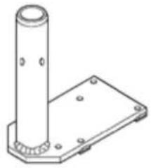 |
 | VW 313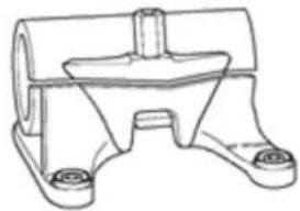 |
 | T1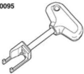 W10-0065 W10-0065 |
Engine, removing and installing
Special tools and equipment
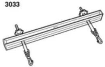
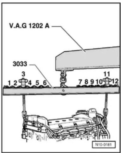
◆ 3033 Lifting tackle
◆ 3269 Engine bracket
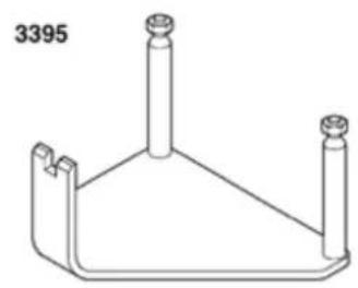
◆ 3395 Engine bracket
◆ VW 313
Support clamp
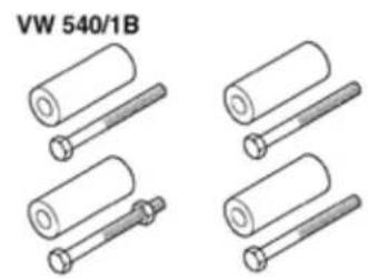
◆ VW 540/1 B Supplementary set
◆ T10095 Puller
10-2
V.A.G 1202J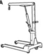 | V.A.G 1306 |
V.A.G 1331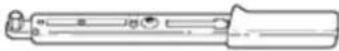 | V.A.G 1332 |
V.A.G 13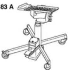 | 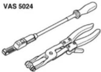 W10-0073 W10-0073 |
W10-0073
◆ VAG 1202 A Workshop crane
◆ VAG 1306 Drip
◆ VAG 1331 Torq wrench (5...50 N
♦ VAG 1332 Torq wrench (40...20(Nm)
◆ VAG 1383 A
Engine/transmis
jack
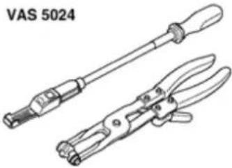
◆ VAS 5024
Assembly tool for spring-type clips
◆ VAS 5085 Step ladder
◆ G 000 100 Grea (models with manual transmission)
◆ Cable tie
10-3
Notes on removing
The engine is removed downward together with the transmission.
CAUTION!
When performing repair work, especially due to the confined conditions in the engine compartment, pay attention to the following:
Route all types of lines (e.g. for fuel, hydraulics, EVAP system, coolant, refrigerant, brake fluid and vacuum) as well as electrical wiring so that the original positions are restored.
- Ensure sufficient clearance to all moving or hot components.
All cable ties which are opened or cut open when removing engine, must be replaced in the same position when installing the engine.
Work sequence
- Remove engine cover.
- First check whether a coded radio is installed. If so, obtain anti-theft coding.
10-4
- With ignition switched off disconnect battery Ground strap.
- Disconnect connectors from ignition coils
Note:
Mark connector and component before disconnecting.
- Remove ignition coils with final out stage cylinders 1...6 using puller T10095.
- Remove battery and battery retainer.
- Remove air cleaner with intake hose:
⇒ Repair Manual, 2.8 Liter VR6 4V Engine Mechanical, Engine Code(s): BDF, Repair (24
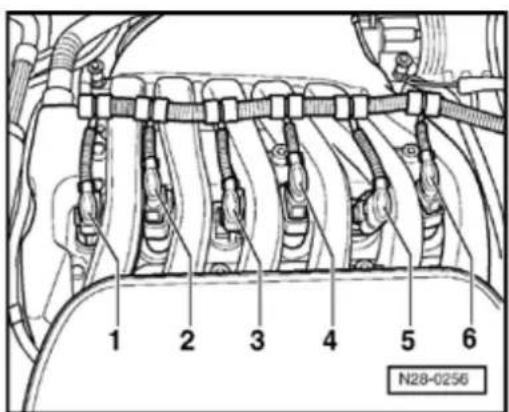
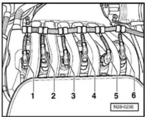
- Disconnect following hose connections are collect fluids that may leak out with a clot
1 - vacuum hose to Throttle valve control m J338-,
2 - fuel return hose (with blue markings),
3 - fuel supply hose (with white markings).
Note:
Press buttons on hose couplings to disconr
WARNING!
Fuel system is under pressure! Before opening the system place a cloth around the connection. Then release pressure by carefully loosening the connection.
- Seal lines to avoid contamination of fuel system.
- Observe rules for cleanliness Page 20-14.
- Remove center, left and right insulation trays:
⇒ Repair Manual, Body Exterior, Repair Group 50 - Pull connectors off thermal switch and coolant fan.
- Remove front bumper:
⇒ Repair Manual, Body Exterior, Repair Group 63 - Bring lock carrier into service position:
⇒ Repair Manual, Body Exterior, Repair Group 50
- Remove intake manifold Page 15-16, Removing and installing cylinder head cover.
Note:
Seal the intake ports in the intake manifold or in the cylinder head with a clean cloth.
- Remove ribbed belt Page 13-19.
- Remove power steering pump on compact bracket and place to side; hoses remain connected:
⇒ Repair Manual, Suspension, Wheels, Steering, Repair Group 48
- Remove securing clamps for power steering pressure line.
Vehicles with air conditioning
- Observe additional information and removal work Page 10-22.
Models with a manual transmission
- Disconnect selector mechanism from transmission:
⇒ Repair Manual, 5 & 6 Spd. Manual Transmission 02M, Repair Group 34
- Separate hydraulic line to slave cylinder for hydraulic clutch:
⇒ Repair Manual, 5 & 6 Spd. Manual Transmission 02M, Repair Group 30
Models with an automatic transmission
- Remove gate selector lever cable from transmission:
⇒ Repair Manual, 5 Spd. Automatic Transmission 09A, Repair Group 37
Continuation for all vehicles
- Disconnect vacuum and breather hoses from engine.
- Separate connectors on following components:
Note:
Mark connector and component before disconnecting.
◆ Engine Coolant Temperature (ECT) sensor -G62- with Engine Coolant Temperature (ECT) sensor -G2-,
◆ After-run coolant pump -V51-,
◆ Valve -1- for camshaft adjustment -N205-,
10-8
◆ Camshaft adjustment valve 1 (exhaust) - N318-,
◆ Camshaft Position (CMP) sensor -G40-,
◆ Camshaft Position (CMP) sensor 2 -G163-,
◆ Injectors (-N30- to -N33-, -N83- and -N84-),
◆ Engine speed (RPM) sensor -G28-,
♦ Knock Sensor (KS) 1 -G61-,
♦ Knock Sensor (KS) 2 -G66-,
Installation locations:
⇒Repair Manual, 2.8 Liter VR6 4V Engine Mechanical, Engine Code(s): BDF, Repair Group 24
- Disconnect all electric wires from transmission, alternator and starter and them move clear.
- Disconnect all other electrical connections from engine as necessary and place to one side.
- Drain coolant Page 19-15.
-
Disconnect coolant hoses quick release couplings from radiator.
-
Pull all coolant hoses off to engine using assembly tool for spring-type clamps VAS 5024.
- Removing drive shafts:
⇒ Repair Manual, Suspension, Wheels, Steering, Repair Group 40 - Remove pendulum support:
⇒ Repair Manual, Suspension, Wheels, Steering, Repair Group 40 - Remove front exhaust pipe with catalytic converter Page 26-1, Removing and installing parts of the exhaust system.
- Remove alternator and compact bracket:
⇒ Repair Manual, Electrical Equipment, Repair Group 27 - Unscrew bracket for Secondary Air Injection (AIR) pump motor -V101- from oil pan and cylinder block Page 26-26, item -17-.
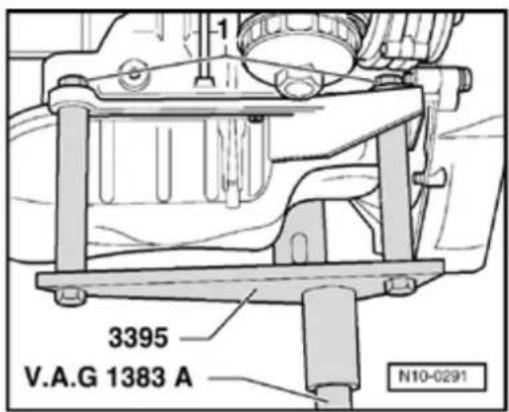
- Install engine bracket 3395 onto engine/transmission jack VAG 1383 A.
10-10

natural_image
Technical line drawing of a mechanical component with two arrows pointing to features, labeled N10-0292 (no readable text or symbols beyond label)- I install engine bracket 3395 to cylinder block and tighten securing nuts -1- to 40 Nm.
- Lift engine and transmission slightly using engine/transmission jack VAG 1383 A.
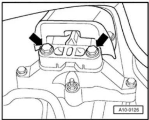
- Unbolt engine side of assembly mounting from engine bracket at top (arrows).
Note:
Use ladder VAS 5085 to remove securing bolts.
10-11
natural_image
Technical diagram of a mechanical component with mounting holes and mounting brackets (no text or symbols)
- Unbolt transmission side of assembly mounting from top of transmission carrier (arrows).
Note:
Use ladder VAS 5085 to remove securing bolts.
- Carefully lower engine with transmission.
Note:
Engine with transmission must be guided carefully, when lowering, to prevent damage to bodywork.
10-12
Securing engine to assembly stand
Note:
When working on the engine it should be secured to assembly stand VW 313 using e bracket 3269 or VW 540 and supplementary 540/1 B.
Work sequence
- Remove transmission.
Models with an automatic transmission
- Secure torque converter to prevent it fall in after engine and transmission are separa
Continuation for all vehicles
- Install engine bracket 3269 or VW 540 ar supplementary set 540/1 B to cylinder bld
- Attach lifting device 3033 as follows and I engine from engine/transmission jack VA using workshop crane VAG 1202.
Vibration damper end: Position 3
Flywheel end: Position 11
- Install engine in support clamp VW 313 u workshop crane VAG 1202 A.
10-13
Notes on installation
Install in reverse sequence ; note the following points:
- Check whether dowel sleeves for centering engine/transmission are installed in cylinder block and install if necessary.
Models with a manual transmission
- Check clutch and clutch operating mechanism and install:
⇒ Repair Manual, 5 & 6 Spd. Manual Transmission 02M, Repair Group 30
- Clean drive shaft splines and lightly grease with G 000 100.
Models with an automatic transmission
- When securing torque converter to drive plate, only use nuts which are authorized for this purpose, Parts catalog.
10-14
Continuation for all vehicles
- When installing engine/transmission assembly, ensure sufficient clearance to engine and transmission mountings and radiator.
- Align engine and transmission mountings Page 10-18.
Note:
Torque settings for assembly mountings Page 10-21.
- Install compact bracket and alternator:
⇒ Repair Manual, Electrical Equipment, Repair Group 27
- Install front exhaust pipe with catalytic converter Page 26-1, Removing and installing parts of the exhaust system.
- Install pendulum support:
⇒ Repair Manual, Suspension, Wheels, Steering, Repair Group 40
- Install drive shafts:
⇒ Repair Manual, Suspension, Wheels, Steering, Repair Group 40
10-15
Models with a manual transmission
- Install gear selector mechanism:
→ Repair Manual, 5 & 6 Spd. Manual Transmission 02M, Repair Group 34 - If necessary adjust gear selector cables:
⇒ Repair Manual, 5 & 6 Spd. Manual Transmission 02M, Repair Group 34 - Install hydraulic line to hydraulic clutch slave cylinder:
→ Repair Manual, 5 & 6 Spd. Manual Transmission 02M, Repair Group 30 - Bleed clutch system:
⇒ Repair Manual, 5 & 6 Spd. Manual Transmission 02M, Repair Group 30
Models with an automatic transmission
- Install gate selector lever cable on transmission, adjust if necessary:
⇒ Repair Manual, 5 Spd. Automatic Transmission 09A, Repair Group 37
10-16
Continuation for all vehicles
- Install power steering pump:
⇒ Repair Manual, Suspension, Wheels, Steering, Repair Group 48 - Install intake manifold Page 15-16, Removing and installing cylinder head cover.
- Install air cleaner with intake hose:
⇒ Repair Manual, 2.8 Liter VR6 4V Engine Mechanical, Engine Code(s): BDF, Repair Group 24
- Install battery and battery retainer.
- Install ribbed belt Page 13-19.
- Check electrical connections and routing:
⇒ Repair Manual, Electrical Equipment, Repair Group 97
- Install center, left and right insulation trays:
⇒ Repair Manual, Body Exterior, Repair Group 50
- Top up coolant level Page 19-15.
- Perform test drive and check DTC memory:
⇒ Repair Manual, 2.8 Liter VR6 4V Fuel Injection & Ignition, Engine Code(s): BDF, Repair Group 01
10-17
- Adapt (match) engine control module to throttle valve control module:
⇒ Repair Manual, 2.8 Liter VR6 4V Engine Mechanical, Engine Code(s): BDF, Repair Group 24 - Perform work sequence "Procedure after interrupting voltage supply":
⇒ Repair Manual, 2.8 Liter VR6 4V Engine Mechanical, Engine Code(s): BDF, Repair Group 24 - Read readiness code:
⇒ Repair Manual, 2.8 Liter VR6 4V Fuel Injection & Ignition, Engine Code(s): BDF, Repair Group 01 - If DTC memory has been erased or engine control module separated from permanent positive supply, generate readiness code again:
⇒ Repair Manual, 2.8 Liter VR6 4V Fuel Injection & Ignition, Engine Code(s): BDF, Repair Group 01
Models with an automatic transmission
- Perform adaptation for Transmission Control Module (TCM):
⇒ Repair Manual, 5 Spd. Automatic Transmission 09A On Board Diagnostic (OBD), Repair Group 01
10-18
Aligning engine and transmission mountings
Special tools and equipment
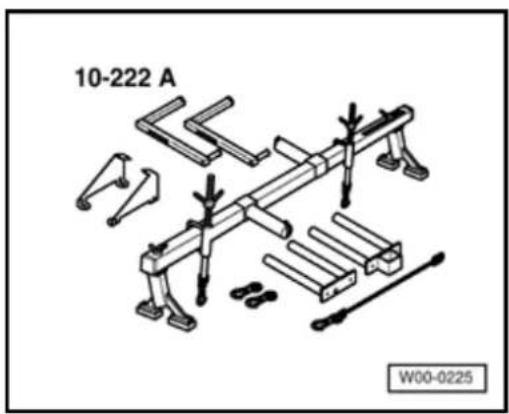
◆ Support device 10-222 A with legs 10-222 A/1 and adapter 10-222 A/3
WARNING!
Before loosening bolts, secure assembly using support device 10-222A.
10-19
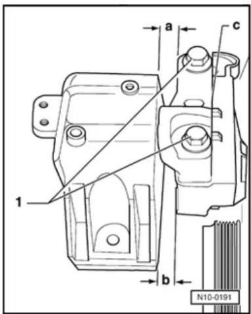
Engine mounting
$$ \mathrm{a} = 1 4. 0 \mathrm{mm} $$
$$ b = \text { at least } 1 0. 0 \mathrm{mm} $$
Both bolt heads -1- must be flush with edge -c-.
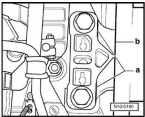
Transmission assembly mounting
Edges -a- and -b- must be parallel to each other.
Note:
Torque settings for assembly mountings Page 10-21.
10-20
Torque settings
| Bolted connections | Torque setting | |
| Bolts, nuts | M6 | 10 Nm |
| M | ||
| M | ||
| M | ||
| M | ||
| Deviations | ||
| Connecting bolts, engine to transmission | M10 | 6 0 Nm |
| Connecting bolts, engine to transmission | M12 | 8 0 Nm |
| Starter to engine and transmission | 45 Nm | |
Note:
Torque settings for assembly mountings Page 10-21.
10-21
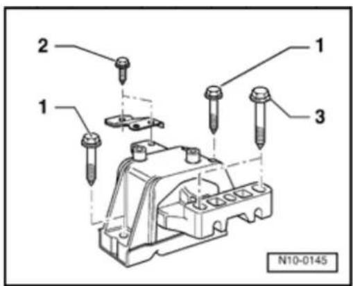
Assembly mounting
Torque settings
Engine mounting
1 Mounting to 40 Nm + body ^1) 90^(14) turn)
2 Support to 20 Nm + mounting at body ^1) 90°( ^1/_4 turn)
3 Mounting to 100 Nm - engine bracket
1) Replace bolts
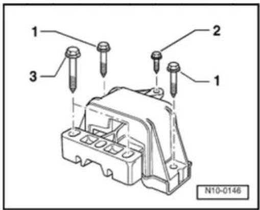
Transmission assembly mounting
1 Mounting to 40 Nm + body ^1) 90°( ^1/_4 turn)
2 Mounting to 20 Nm + body ^1) 90^(^1/_4 turn)
3 Mounting to 100 Nm - transmission console
1) Replace bolts
10-22
Additional information and assembly work on models with air conditioning
WARNING!
The air conditioning refrigerant circuit must not be opened.
Note:
The refrigerant circuit must only be opened in workshops with trained personnel and the necessary range of tools and workshop equipment.
To prevent damage to the condenser as well as to the refrigerant lines/hoses, ensure that lines and hoses are not stretched, kinked or bent.
To facilitate removal and installation of the engine without having to open the refrigerant circuit:
- Remove retaining clamp(s) from refrigerant lines.
- Remove air conditioner compressor:
⇒ Repair Manual, Heating & Air Conditioning, Repair Group 87; Removing and installing compressor bracket
- Secure air conditioning compressor to body so that refrigerant lines/hoses are not under stress.
Engine, disassembli and assembling
Note:
When working c the engine it should be secured to assembly stand VW 313 using engine bracket 3269 or VW 540 and supplement set 540/1 B.
If when repairing engine, metal shavings or large amounts of sma metal particles a found in the eng oil, caused by partial seizure o crankshaft or conrod bearings perform the following work sequences to prevent consequential damage once repairs are complete:
-- Thoroughly clean oil passages
-- Replace oil spray jets
-- Replace oil cooler
-- Replace oil filter
-- Replace oil non-return va
13-2
I⇒ Page 13-3
13- 12
13-3

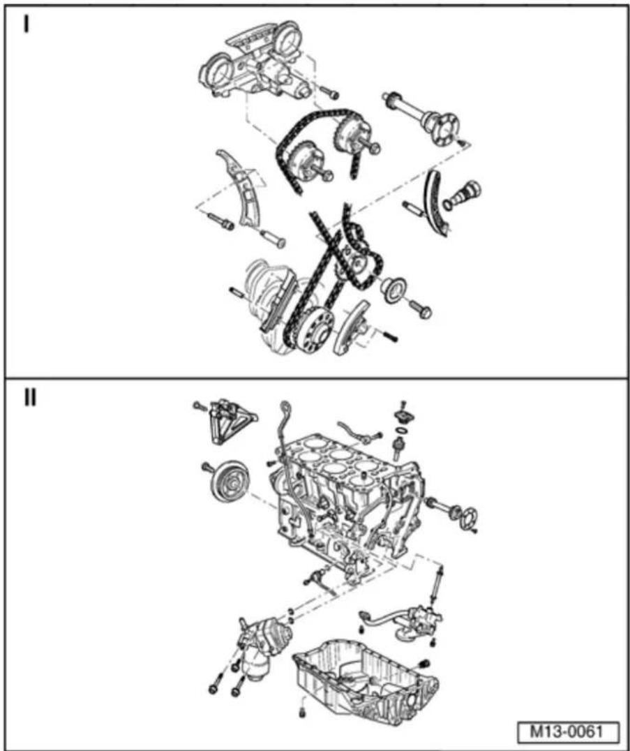
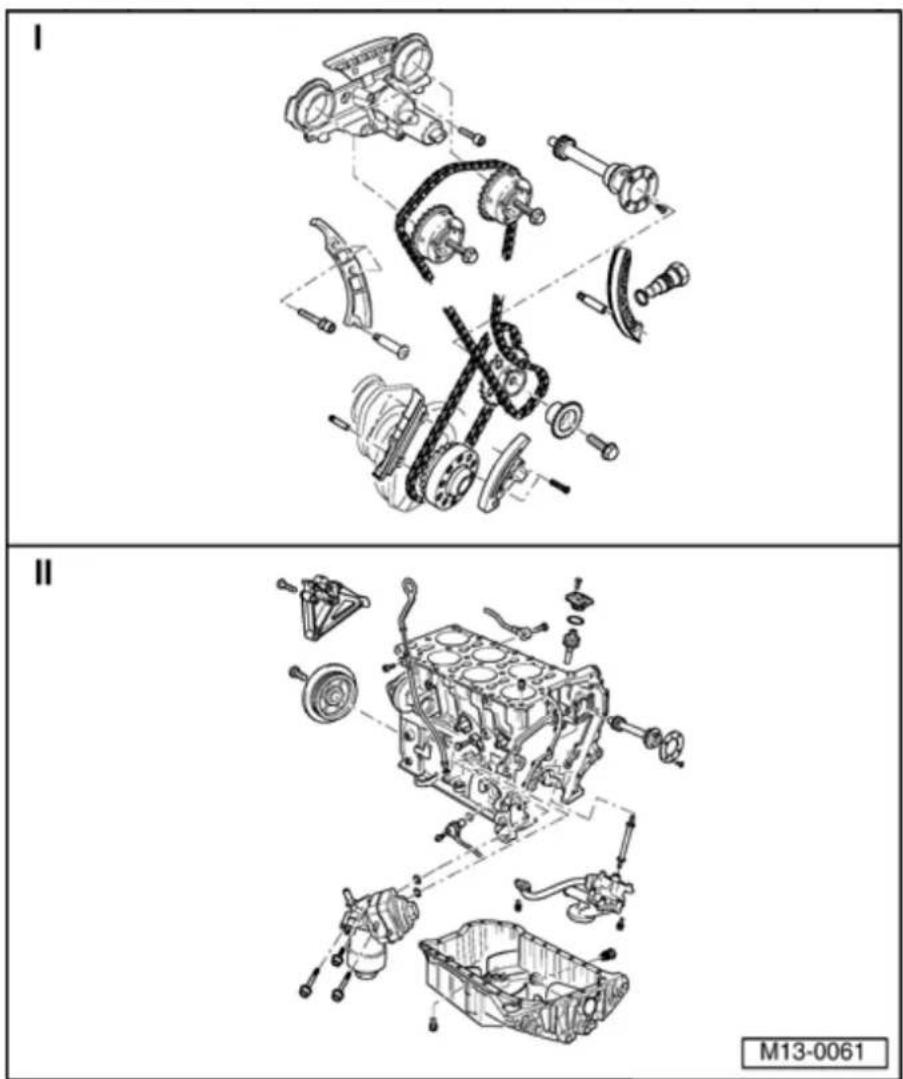
Part I
1 - Control housing
♦ Lubricate contact surfaces of oil seal when installing
♦ Removing and installing ⇒ Page 15-69, Removing and installing camshaft
◆ Disassembling and assembling ⇒ Page 15-64, Fig. 6
◆ Check screen of control housing for soiling before installing → Page 15-64, Fig. 7
2 - 8 Nm
♦ Replace
3 - Camshaft roller chain
Mark direction of rotation before removing (installation
position) Fig. 1
◆ Installing → Page 15-39, Adjusting valve timing
13-4

4 - Exhaust camshaft timing adjuster
◆ Marking: 32A
◆ Turn engine over only when camshaft timing adjuster is installed
◆ Check camshaft timing adjustment ⇒ Page 15-82
◆ Installing → Page 15-39, Adjusting valve timing
5 Intermediate - shaft
6 - Thrust washer
7 - 8 Nm
◆ Insert with locking compound D 000 600 A2
8 - Tensioning plate
◆ For camshaft roller chain item 3
9 - Mounting stud, 10 Nm
◆ For tensioning plate item 8
13-5
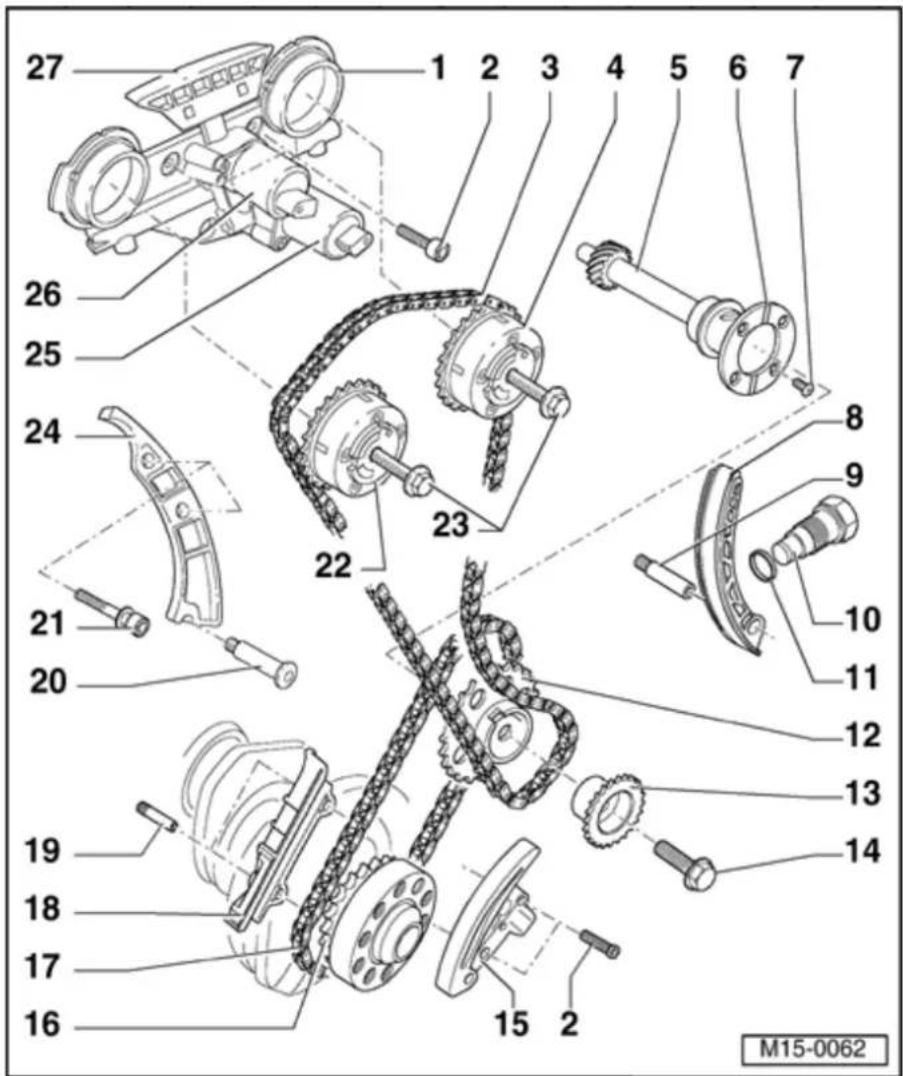
10 Chain
- tensioner, 40 Nm
◆ For camshaft roller chain item 3
◆ Turn engine over only when chain tensioner is installed
11 - Seal
◆ Replace if damaged or leaking
12 - Chain sprocket
◆ For roller chain item 17
◆ Installing → Page 15-39, Adjusting valve timing
13 - Chain sprocket
◆ For camshaft roller chain item 3
◆ Installing
⇒ Page
15-39,
Adjusting
valve
timing

14 60 Nm
- plus additional 14 turn (90 °) further
◆ Replace
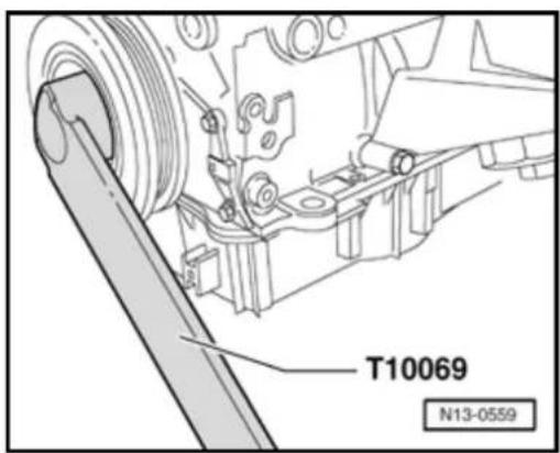
◆ Use counter support T10069 to loosen and tighten ⇒ Page 15-39, Adjusting valve timing
15 Chain
- tensioner with tensioning rail
◆ For roller chain item 17
Before installation release the locking device in the chain tensioner with a small screwdriver and press the tensioning plate against the chain tensioner
◆ Turn engine over only when chain tensioner is installed
16 - Drive sprocket
♦ Integral part of crankshaft
◆ Ground down tooth aligned with main bearing joint = TDC cyl. 1 ⇒ Page 15-39, Adjusting valve timing
13-7

17 - Roller chain
Mark direction of rotation before removing (installation position) ⇒ Fig. 1
◆ Installing ⇒ Page 15-39, Adjusting valve timing
18 - Guide rail
◆ For roller chain item 17
◆ Remove and install together with roller chain ⇒ Page 15-39, Adjusting valve timing
19 - Stud without collar, 10 Nm
◆ For guide rail item 18
20 - 10 Nm
◆ For guide rail item 24
21 - 23 Nm
◆ For guide rail item 24

13-8
22 Intake
- camshaft timing adjuster
◆ Marking: 24E
◆ Turn engine over only when camshaft timing adjuster is installed
◆ Check camshaft timing adjustment ⇒ Page 15-82
◆ Installing → Page 15-39, Adjusting valve timing
23 60 Nm
- plus additional 14 turn (90) further
◆ Replace
◆ Contact surface of sensor wheel on bolt head must be dry for assembly
◆ To remove
and
install,
use a 32
mm open
jaw
spanner
on
camshaft
to counter
support
→ Page
15-69;
Removing
and
installing
camshaft
13-9

24 - Guide rail
◆ For camshaft roller chain item 3
25 Camshaft
- adjustment valve 2 (exhaust) - N318-
◆ Check camshaft timing adjustment → Page 15-82
Mark connector and component before pulling connector off
◆ Checking activation:
⇒ Repair Manual, 2.8 Liter VR6 4V Fuel Injection & Ignition, Engine Code(s): BDF, Repair Group 01
26 Valve 1 for
- camshaft adjustment -N205-
◆ For intake camshaft
◆ Check camshaft
timing
adjustment
⇒ Page
15-82
Mark
connector
and
component
before
pulling
connector
off
◆ Checking
activation:
⇒ Repair
Manual, 2.8
Liter VR6 4V
Fuel Injection &
Ignition, Engine
Code(s): BDF,
Repair Group
01
13-10

27 - Guide rail
◆ For camshaft roller chain item 3
◆ Clipped into control housing
13-11


Fig. 1 Marking roller chains
- Mark roller chains before removing (e.g. with paint, arrow pointing in direction of rotation).
Note:
Do not mark chain with a punched mark, notch or similar!
13-12

Part II
1 - 45 Nm
2 - Engine bracket
3 - 8 Nm
◆ Secured to intake manifold
4 - Dipstick
◆ The oil level must not exceed the max. mark!
◆ Markings ⇒ Page 17-8, Fig. 2
5 - Guide tube
◆ For dipstick
◆ Secured by a bolt to intake manifold
13-13

6 - Cylinder block
♦ Removing and installing sealing flange and dual-mass flywheel → Page 13-22
♦ Removing and installing crankshaft ⇒ Page 13-34
◆ Disassembling and assembling piston and conrod ⇒ Page 13-39
7 - Knock Sensor (KS) 1 - G61-
◆ 3-pin
◆ Installation location: Between cyl. 1 and cyl. 3
The contact surfaces between knock sensor and cylinder block must be free of
corrosion, dirt and grease.
◆ Checking:
⇒ Repair Manual, 2.8 Liter VR6 4V Fuel Injection & Ignition, Engine Code(s): BDF, Repair Group 01
8 - 20 Nm
◆ Torque setting influences the function of knock sensor
13-14
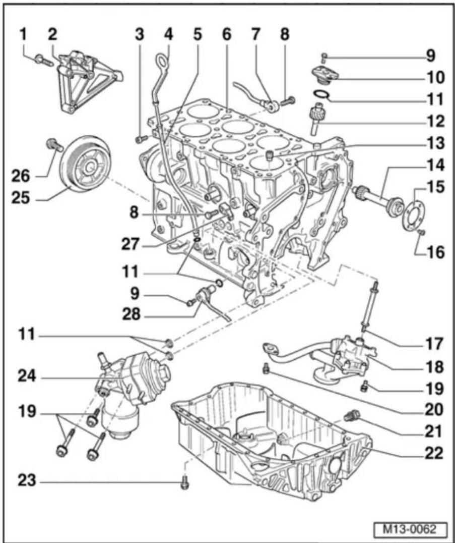
9 - 10 Nm
10 - Oil pump drive cover
11 - O-ring
♦ Replace
♦ Lubricate before installing
12 - Oil pump drive
13 - Oil non-return valve, 5 Nm
◆ Observe installation position
◆ Clean if badly soiled
◆ See note ⇒ Page 13-1
14 Intermediate - shaft
15 - Thrust washer
16 - 10 Nm
◆ Install with locking compound "D6"
17 - Drive shaft
◆ For oil pump drive
13-15

18 - Oil pump
◆ Disassembling and assembling ⇒ Page 17-12
◆ Coat oil pressure pipe at cylinder block and oil pump housing with sealing compound AMV 188 001 02
19 - 23 Nm
20 - 8 Nm
◆ Insert with locking compound D 000 600 A2
21 - Oil drain plug, 30 Nm
♦ Replace if leaking
22 - Oil pan
♦ Removing and installing ⇒ Page 17-15
23 - 12 Nm
13-16

24 - Oil filter housing
◆ See note ⇒ Page 13-1
◆ Disassembling and assembling ⇒ Page 17-9
◆ Coolant hose connection diagram ⇒ Page 19-11
25 - Vibration damper
♦ Removing and installing ribbed belt ⇒ Page 13-19
26 - 100 Nm plus additional ^1/_4 turn (90) ^ further
♦ Replace
◆ Use counter support T10069 to loosen and tighten ⇒ Fig. 1
◆ Tighten using torque wrench VAG
1601
13-17

27 - Knock Sensor (KS) 2 - G66-
◆ 2-pin
◆ Installation location: Between cyl. 4 and cyl. 6
◆ The contact surfaces between knock sensor and cylinder block must be free of corrosion, dirt and grease.
- Checking:
⇒ Repair Manual, 2.8 Liter VR6 4V Fuel Injection & Ignition, Engine Code (s): BDF, Repair Group 01
28 - Engine speed (RPM) sensor -G28-
◆ Checking:
⇒ Repair Manual, 2.8 Liter VR6 4V Fuel Injection & Ignition,
Engine Code
(s): BDF,
Repair Group
01
13-18


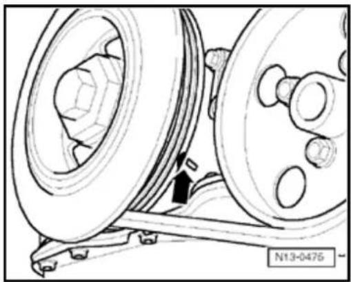
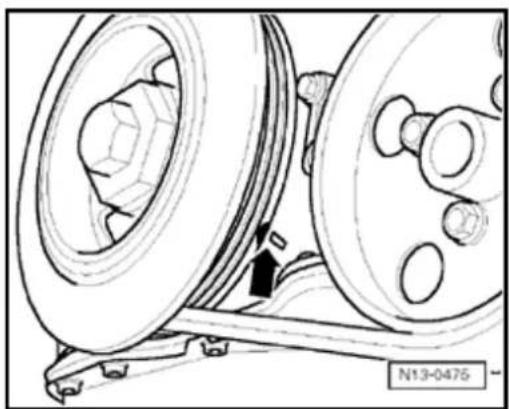
Fig. 1 To loosen and tighten securing bolt, hold vibration damper with counter support T10069
Note:
◆ Vibration damper securing bolt must be replaced.
◆ Tighten securing bolt with torque wrench VAG 1601.
13-19
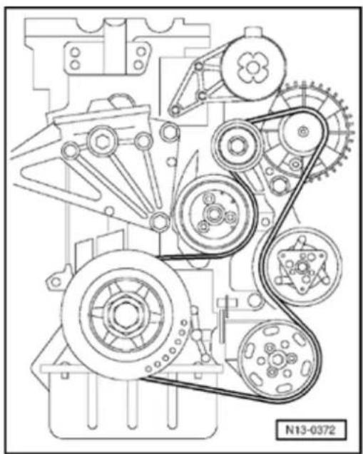
Ribbed belt, removing and installing
Special tools and equipment
◆ VAS 5024 Assembly tool for spring-type clips
Hex bolt M8x45
Removing ribbed belt
Note:
Mark ribbed belt direction of rotation before removing. Make sure ribbed belt is seated correctly in pelt pulley when installing.
- Remove engine cover.
13-20
natural_image
Mechanical assembly diagram showing engine components and a numbered component (N13-0672), no readable text or symbols beyond the label.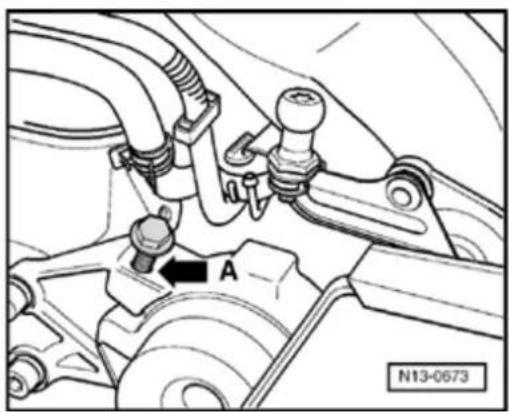
natural_image
Mechanical assembly diagram showing a clamping device with labeled component A and reference number N13-0673 (no text or symbols beyond labels)
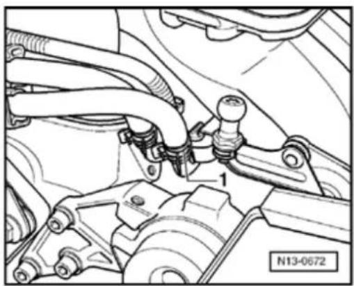
- Pull off return hose -1- (with blue marking) and collect fuel that may leak out with a cloth.
- Seal lines to avoid contamination of fuel system.
- Observe rules for cleanliness Page 20-14.
- Removing right hand insulation tray:
⇒ Repair Manual, Body Exterior, Repair Group 50
- Mark direction of rotation of ribbed belt.

- Screw M8x45 bolt into threaded hole -A- of tensioning element until ribbed belt is no longer under tension.
Note:
Screw bolt in sufficiently so that the ribbed belt can be removed and no further, otherwise the tensioner element housing may be damaged.
- Remove ribbed belt.
13-21
Installing ribbed belt
- Install in reverse order.
Note:
Make sure, before installing ribbed belt, ancillaries (alternator, air conditioning compressor, power steering pump) are slightly.
When installing the ribbed belt observe a direction of rotation and that the belt is s correctly in the belt pulleys.
natural_image
Technical line drawing of a mechanical gear assembly with pulleys and shafts (no text or symbols)
- Install ribbed belt.
- Remove M8 bolt from tensioner!
After completing repairs always:
- Start engine and check belt running.
- Install right-hand insulation tray:
⇒ Repair Manual, Body Exterior, Repair Gr - Install engine cover.
13-22
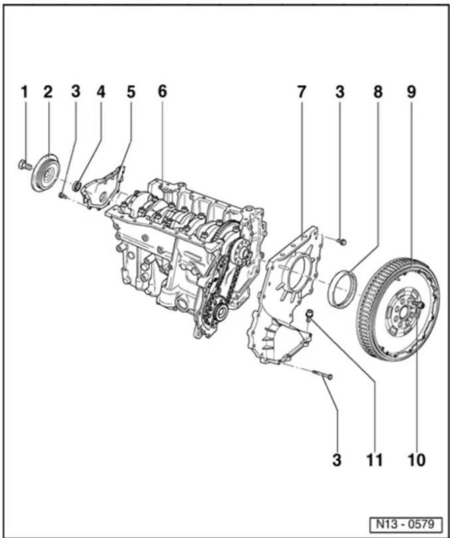
Sealing flanges and dual- mass flywheel, removing and installing
Note:
◆ Servicing clutch:
⇒ Repair Manual, 5 & 6 Spd. Manual Transmission 02M, Repair Group 30
When working on the engine it should be secured to assembly stand VW 313 using engine bracket 3269 or VW 540 and supplementary set 540/1 B.
◆ The sealing flange (item 7) can be removed and installed when cylinder head is installed.

13-23
1 - 100 Nm plus additional ^1/4 turn (90) further
◆ Replace
◆ Use counter support T10069 to loosen and tighten ⇒ Page 13-27, Replacing crankshaft oil seal - vibration pulley end
◆ Tighten using torque wrench VAG 1601
2 - Vibration damper
♦ Removing and installing ribbed belt ⇒ Page 13-19
3 - 8 Nm
4 - Seal
◆ PTFE seal version
◆ Marking: With no inner
coil spring
◆ Do not additionally lubricate the oil seal sealing lip
Before installing, remove oil remains from crankshaft journal with a clean cloth
♦ Replacing ⇒ Page 13-27
13-24

5 - Sealing flange
◆ Coat sealing surfaces with sealing compound AMV 188 001 02
6 - Cylinder block
♦ Removing and installing crankshaft ⇒ Page 13-34
◆ Disassembling and assembling piston and connecting rod ⇒ Page 13-39
7 - Sealing flange
◆ Coat sealing surfaces with sealing compound AMV 188 001 02 ◆ Seal sealing surface to cover ⇒ Page 15-39, Adjusting timing
13-25

8 - Seal
◆ PTFE seal version
◆ Marking: With no inner coil spring
Do not additionally lubricate the oil seal sealing lip
◆ Remove with extractor hook 2086
Before installing, remove oil remains from crankshaft journal with a clean cloth.
◆ Install over sleeve 2003/2A
◆ Pull in onto limit stop with press sleeve 2003/1
9 Dual-mass
- flywheel/drive plate
♦ Removing and installing
drive
plate
Page 13-
31
13-26

10 60 Nm
- plus additional 14 turn (90) ^ further
◆ Replace
◆ Use counter support T10069 to loosen and tighten
11 - 23 Nm
13-27
| 3203 | 3266 |
| T10069 | T10053 |
| V.A.G 1601 | V.A.G 1332 |
Crankshaft oil seal (vibration damper end), replacing
Special tools and equipment
◆ 3203 Oil seal extractor
◆ 3266 Sleeve
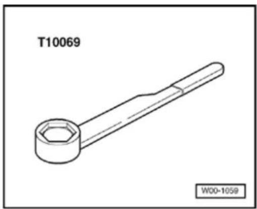
◆ T10069 Counter support
◆ T10053/1 Guide sleeve
◆ VAG 1601 Torque wrench (150...800 Nm)
◆ VAG 1332 Torque wrench (40...200 Nm)
13-28

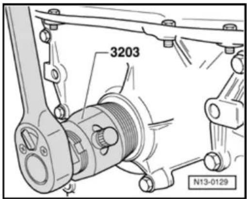
Removing
- Remove ribbed belt Page 13-19.

- Remove vibration damper. To do this, hold vibration damper with counter support T10069.
- Unscrew inner part of oil seal extractor 3203 three turns (approx. 4 mm) out of the outer part and lock with knurled screw.

- L ubricate threaded head of oil seal extractor 3203, place it in position and exerting firm pressure screw it as far as possible into oil seal.
- Loosen knurled screw and turn inner part against crankshaft until oil seal is pulled out.
13-29
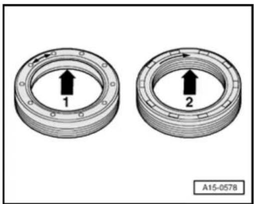
Installing
Note:
natural_image
Two circular mechanical components with arrows indicating direction, labeled 1 and 2, no text or symbols present.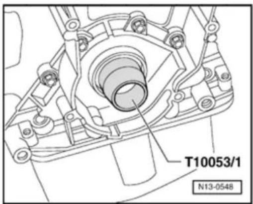
A PTFE seal (Teflon) -2- is gradually being introduced instead of the inner coil spring type seal-1-. This has a wider sealing lip. PTFE seals are fitted free of oil and grease. When a PTFE seal is installed, then only such a seal may be installed as a replacement part!
- Before installing, remove oil remains from crankshaft journal with a clean cloth.
- Install guide sleeve T10053/1 onto crankshaft journal and carefully slide seal onto guide sleeve
13-30
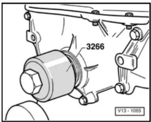

- Press seal against limit stop using press sleeve from 3266. Use old mounting bolt for vibration damper for this purpose.
- Install vibration damper and lock it with counter support T10069. - Tighten new bolt to 100 Nm plus additional 90° ( ^1/_4 turn - turning further can be done in several stages).
Note:
♦ Vibration damper securing bolt must be replaced.
♦ Tighten securing bolt with torque wrench VAG 1601.
- Install ribbed belt Page 13-19.
13-31
Drive plate, removing and installing
Special tools and equipment

◆ T10069 Counter support
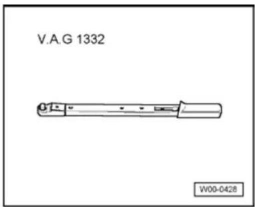

♦ VAG 1332 Torque wrench (40...200 Nm)
♦ Depth gauge
♦ Straight edge
13-32
Removing

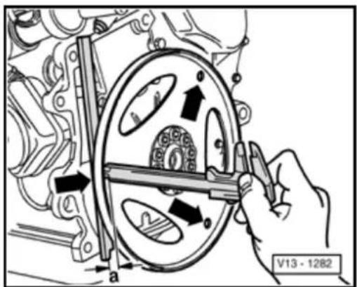
- Remove drive plate. To do this, hold vibration damper with counter support T10069.
- Loosen drive plate securing bolts using cross-over sequence and remove them.
- Remove drive plate.
Installing
- Position drive plate on crankshaft
- Insert at least 3 old bolts and tighten to 30 Nm.

- Check dimension -a- through three holes for securing torque converter using a straightedge and depth gauge and calculate average.
- Compare average (measured distance + thickness of straightedge) with specification.
Specification: 15.7...16.5 mm
13-33
natural_image
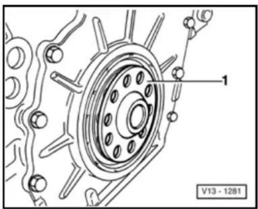
Technical diagram of a mechanical component with labeled parts (no readable text or symbols)If the specification is not obtained:

- Remove drive plate again and install appropriate shim -1-.
Note:
Only one shim of the appropriate thickness may be used to compensate.
If the specification is obtained:
- Install new cylinder head bolts and tighten hand tight.
- Tighten securing bolt to 60 Nm plus additional 90° ( ^1/_4 turn - turning further can be done in several stages).
13-34
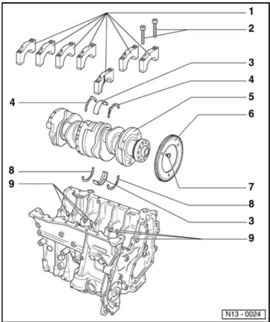
Crankshaft, removing and installing
Note:
When working on the engine it should be secured to assembly stand VW 313 using engine bracket 3269 or VW 540 and supplementary set 540/1 B.
Before removing the crankshaft, ensure that a suitable place has been prepared to ensure that the sensor wheel (item - 6-) does not make contact or become damaged.
When changing bearing shells ensure that bearing shells of same color code are used.
1 - Bearing cap
♦ Bearing cap 1: Vibration damper end
♦ Bearing cap 5 with recesses for thrust washers
♦ Bearing shell retaining lugs (cylinder block/bearing cap) must be on the same side

13-35
2 - 30 Nm plus additional ^1/_2 turn (180)° further
◆ Replace
♦ Turning 2 x 90 ° further is permitted
3 - Bearing shells 1...7
♦ Observe note before removing ⇒ Page 13-34
◆ For bearing cap without oil groove
◆ For cylinder block with oil groove
Do not interchange used bearing shells (mark location)
4 - Thrust bearing
◆ For bearing cap 5
◆ Check locating point
13-36

5 - Crankshaft
◆ Observe note before removing ⇒ Page 13-34
♦ Axial clearance new: 0.07...0.24 mm, Wear limit: 0.30 mm
◆ Check radial clearance with Plastigage, New: 0.02...0.06 mm, Wear limit: 0.10 mm
Do not turn crankshaft when checking the radial clearance
♦ Crankshaft dimensions: Main bearing: 59.958...59.978 mm Conrod bearing: 53.958...53.978 mm
6 - Sensor wheel
For Engine speed (RPM)
sensor - G28-
◆ Replace
◆ Installing
⇒ Fig. 1
13-37

7 - 10 Nm plus additional ^1/_4 turn (90)° further
♦ Replace
♦ Observe sequence when tightening ⇒ Fig. 1
8 - Thrust bearing
◆ For bearing cap 5
◆ Check locating point
9 - Oil spray jet
◆ For crankshaft bearings 2...7
◆ For piston cooling
◆ Opening pressure: 2.0 bar
♦ Removing and installing Page 17-7, Fig. 1
◆ See note ⇒
13-38
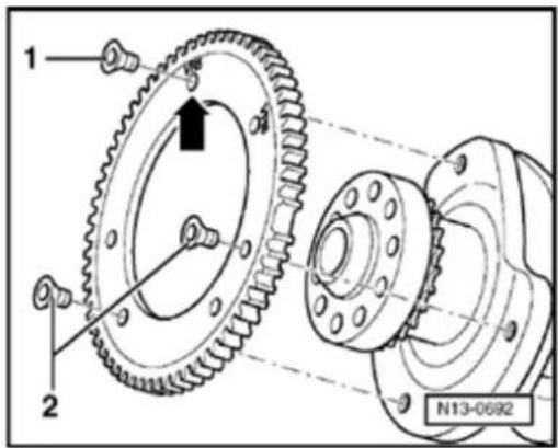

Fig. 1 Installing sensor wheel to crankshaft
Special tools and equipment
♦ VAG 1331 Torque wrench (5...50 Nm)
◆ D 000 600 A2 Locking compound
Work sequence
Make sure crankshaft/sensor wheel contact surfaces are free of oil and grease.
- Apply a thin coat of locking compound D 000 600 A2 to contact surfaces of crankshaft and sensor wheel for additional security.
- Check that when installing "VR6" (arrow) is marked at individual threaded holes.
- Tighten all new securing bolts lightly by hand.
- Tighten securing bolt -1-to 10 Nm plus additional 90° ( ^1/_4 turn).
- Tighten securing bolts -2- to 10 Nm plus additional 90^ (^1/_4 turn).

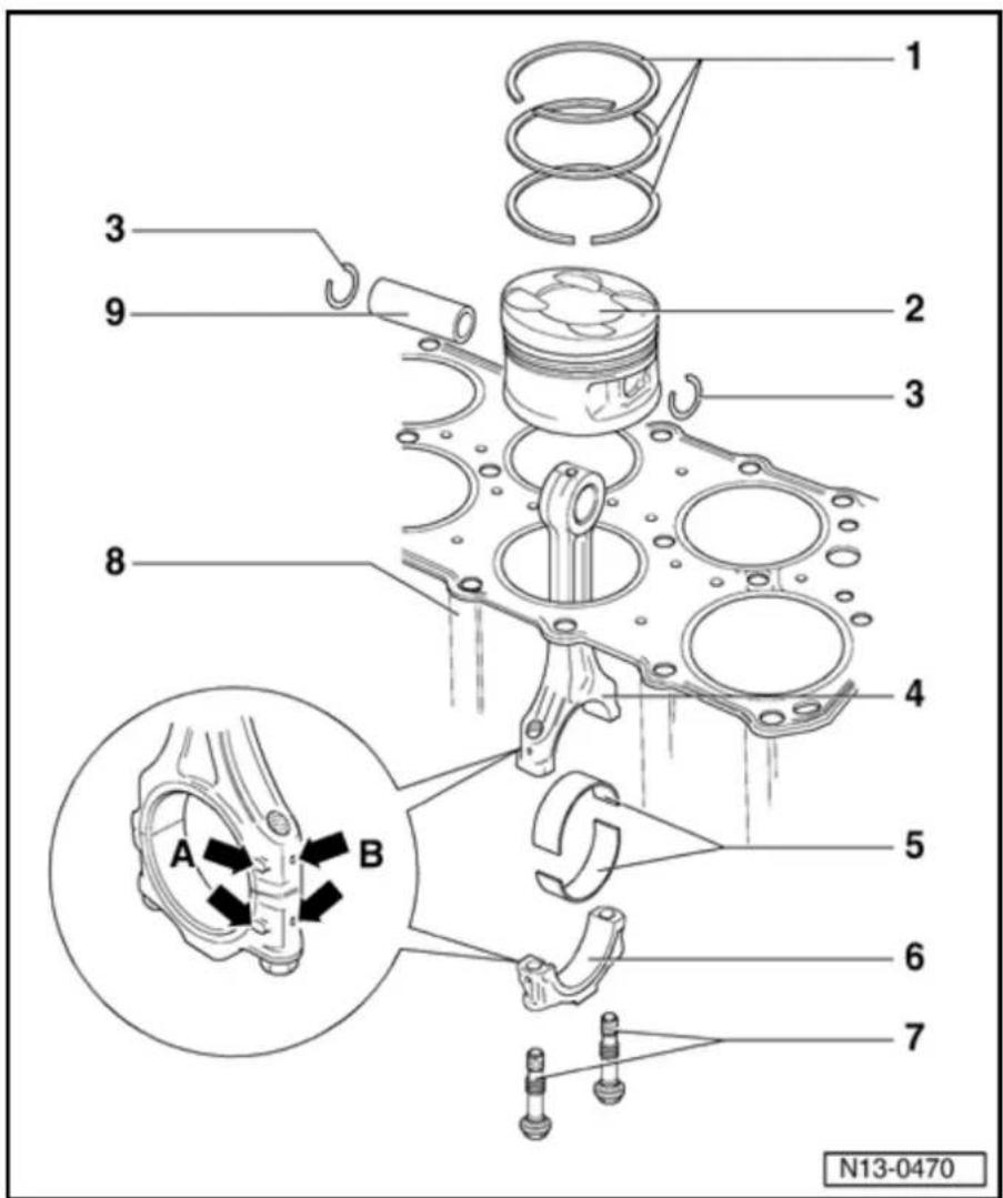
Piston and connecting rod, disassembli and assembling
1 - Piston rings
♦ Offset gaps 120°
◆ Use piston ring pliers to remove and install
◆ "TOP" face towards pis crown
◆ Checking ri gap ⇒ Fig.
◆ Checking ri to groove clearance = Fig. 2
2 - Piston
◆ Checking = Fig. 3
Mark installation position to connecting and cylinder
◆ Flatter side piston crow faces towal center of cylinder blc
◆ Install with piston installation (funnel) 32°
⇒ Fig. 5
3 - Snap ring
13-40

4 - Conrod
♦ Only replace as a set
◆ Mark position to cylinder -B-
◆ Installation position: Marks -A- must be aligned above one another
5 - Bearing shell
◆ Observe installation position
◆ Do not interchange used bearing shells
◆ Lugs on bearing shells must fit tightly in recesses
♦ Axial clearance, New: 0.05...0.35 mm, Wear limit: 0.40 mm
Check radial clearance with
Plastigage:
New:
0.02...0.07
mm, Wear
limit: 0.10
mm. Do
not turn
crankshaft
when
checking
radial
clearance
13-41
6 - Conrod bearing cap
◆ Mark position to cylinder -B-
◆ Installation position: Marks -A- must be aligned above one another
7 - 30 Nm plus additional ^1/_4 turn (90 °) further
♦ Replace ♦ Oil thread and contact surface
◆ To measure radial clearance tighten to 30 Nm, but do not turn further
8 - Cylinder block
◆ Checking cylinder bore ⇒ Fig. 4
♦ Removing and
installing
crankshaft
⇒ Page
13-34
♦ Piston and cylinder dimensions ⇒ Page 13-48
13-42

9 - Piston pin
If difficult to remove, heat piston to 60 °C
◆ Remove and install with drift VW 222a
13-43
natural_image
Technical line drawing of a mechanical component with labeled parts (a, b) and a tool inserted into a cylindrical feature (no text or symbols beyond labels)
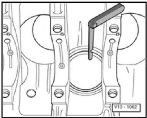
Fig. 1 Checking piston ring gap
Special tools and equipment
Feeler gauge
Test sequence
- Push ring squarely from above down to approx. 15 mm from bottom end of cylinder. To do this use a piston without rings.
| Piston ring | Gap | ||
| New | Wear limit | ||
| Compression ring | mm | 0.20...0.40 | 1.0 |
| Tapered-stepped ring | mm | 0.20...0.40 | 1.0 |
| Oil scraper ring | mm | 0.25...0.50 | 1.0 |
13-44
natural_image
Line drawing of a piston and curved pipe assembly (no text or symbols)
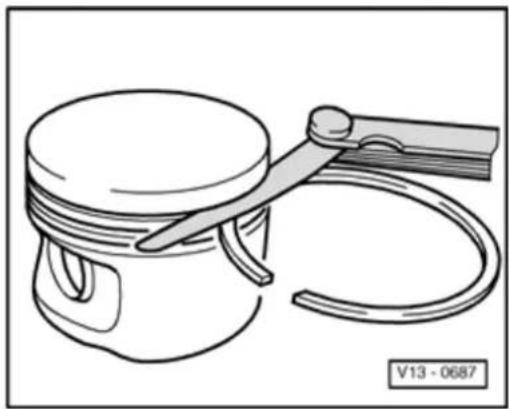
Fig. 2 Checking ring to groove clearance
Special tools and equipment
◆ Feeler gauge
Test sequence
- Clean ring groove before checking.
| Piston ring | Ring to groove clearance | ||
| New | Wear limit | ||
| Compression ring | mm | 0.04...0.08 | 0.15 |
| Tapered-stepped ring | mm | 0.02...0.06 | 0.15 |
| Oil scraper ring | mm | 0.03...0.06 | 0.15 |
13-45
natural_image
Illustration of hands using a mechanical device to adjust a component (no text or symbols visible)
Fig. 3 Checking piston
Special tools and equipment
◆ External micrometer 75...100 mm
Test sequence
- Take measurement approx. 6 mm from lower edge of piston skirt and offset 90° to piston axis.
Deviation from nominal dimension: max. 0.04 mm
13-46
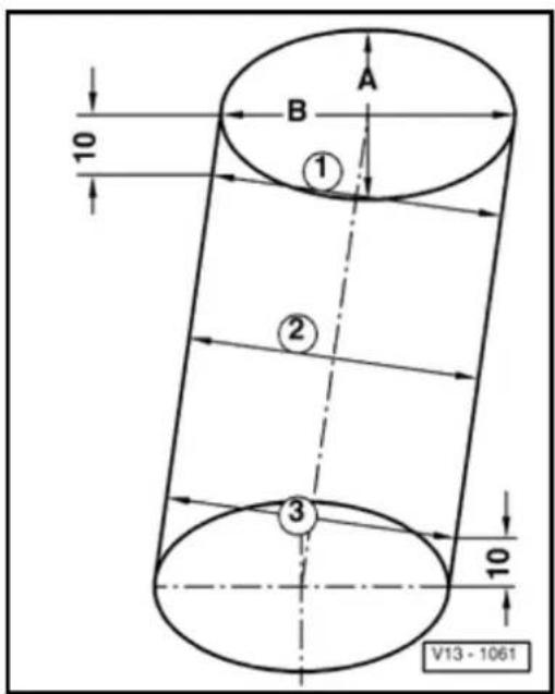

Fig. 4 Checking cylinder bores
Special tools and equipment
◆ Internal dial gauge 50...100 mm
Test sequence
- M easure bores at 3 locations in both directions -A- across engine and -B- in line with crankshaft.
Deviation from nominal dimension: max. 0.08 mm
Note:
The cylinder bores must not be measured if the cylinder block is mounted on a repair stand with engine bracket 3269 or VW 540, as incorrect measurements would then result.
13-47
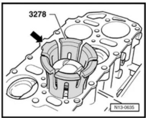

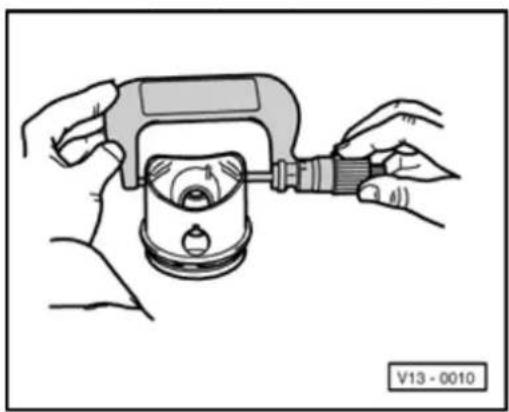
Fig. 5 Installing pistons with piston installation tool (funnel) 3278
Special tools and equipment
◆ 3278 Funnel
Note:
If a new installation tool (funnel) is used to install the pistons, first pass piston with oiled piston rings through the funnel twice and remove the resulting metal shavings if necessary. Only then install piston with piston rings.
Work sequence
- Push piston by hand into oiled installation tool (funnel). Flat side of piston crown must face toward tab on funnel (arrow).
- Hold installation tool (funnel) on upper edge and press piston in with both thumbs.
- Push piston in until it protrudes approx. 15 mm from lower edge of tool (funnel).
- Insert piston into appropriate cylinder bore. Tab on tool (arrow) must face center of cylinder block.
- Press installation tool (funnel) tightly against cylinder block and push piston in.
13-48
Piston and cylinder dimensions
| Honing dimension | Piston diameter | Cylinder bore diameter | |
| Basic dimension | mm | 80.965 | 81.010 |
| 1st oversize | mm | 81.465 | 81.510 |
| 2nd oversize | mm | 81.965 | 82.010 |

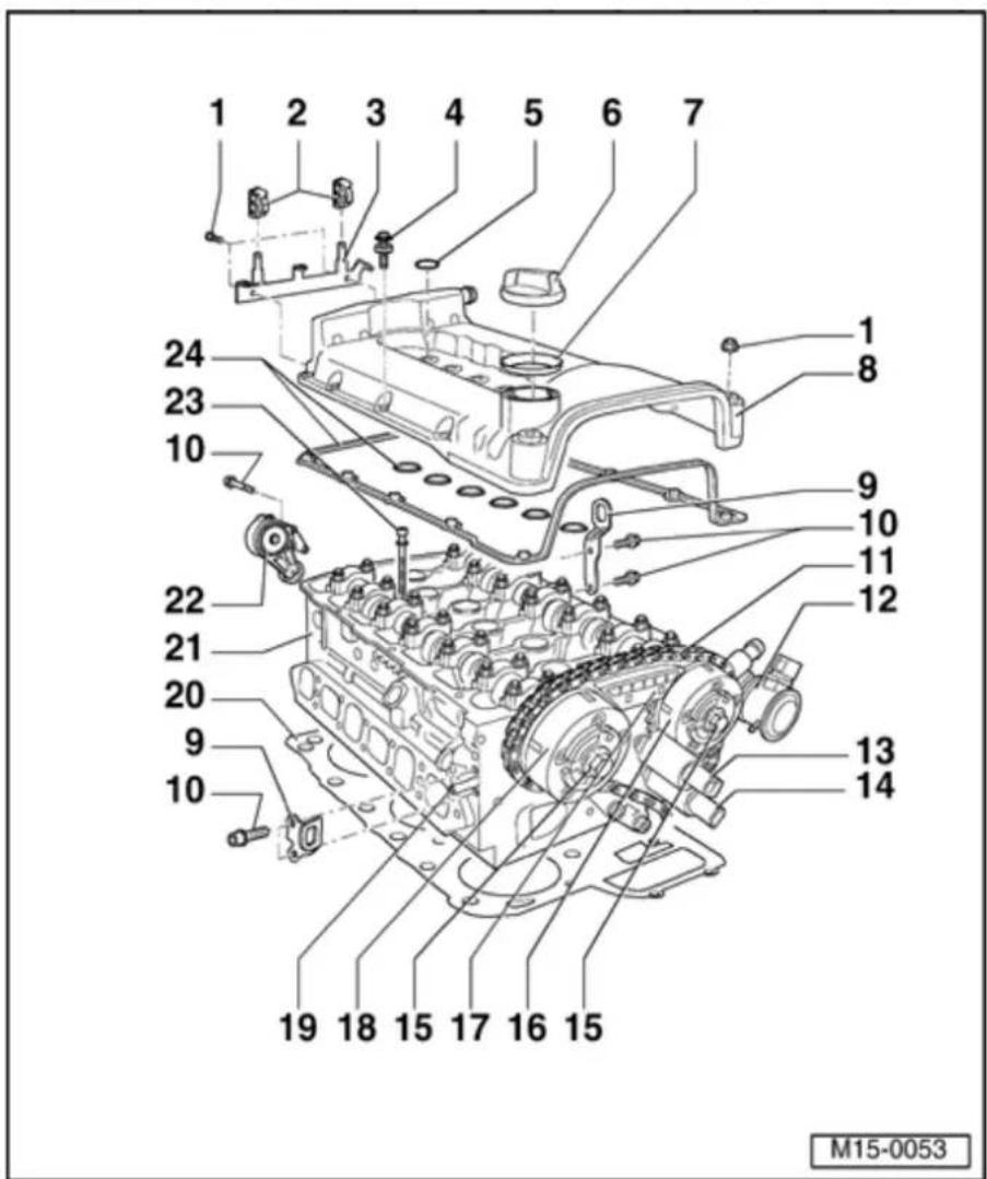
Cylinder head, servicing
Note:
If an exchange cylinder head is installed, all contact surfaces between bearing elements, roller rocker fingers and cam running surfaces of camshaft must be oiled before installing cylinder head cover.
◆ The plastic protectors installed to protect the open valves must only be removed immediately before installing the cylinder head.
When replacing the cylinder head the entire coolant quantity must be replaced.
15-2

♦ Removing and installing intake manifold ⇒ Page 15-16; Removing and installing cylinder head.
◆ Disassembling and assembling intake manifold:
⇒ Repair Manual, 2.8 Liter VR6 4V Fuel Injection & Ignition, Engine Code(s): BDF, Repair Group 24
♦ Removing and installing cover ⇒ Page 15-11.
◆ Checking compression pressure ⇒ Page 15-48.
1 - 8 Nm
2 - Bracket
◆ For fuel lines
3 - Supporting frame
4 - 8 Nm
◆ With spacer sleeve and sealing ring
◆ Replace sealing ring if
damaged
15-3

5 - O-ring
♦ Replace if damaged
♦ Lubricate before installing
◆ For ignition coils with final output stage
6 - Sealing cap
◆ Replace seal if damaged
7 - Boot
♦ Replace if damaged
8 - Cylinder head cover
◆ Replace if damaged
♦ Removing and installing ⇒ Page 15-16
9 - Lifting eye
10 - 23 Nm
15-4
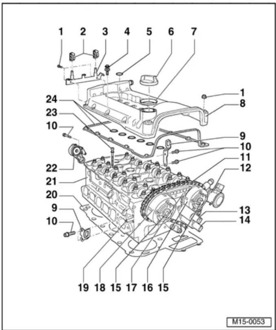
11 - Camshaft roller chain
Mark direction of rotation. before removing (installation position) ⇒ Page 13-11, Fig. 1
◆ Installing ⇒ Page 15-39, Adjusting valve timing
12 - Combi-valve
♦ Removing and installing ⇒ Page 26-24, Removing and installing parts of the secondary air system
◆ Checking ⇒ Page 26-41
13 - Valve -1- for camshaft adjustment -N205-
◆ For intake camshaft Check camshaft
timing
adjustment
⇒ Page
15-82
Mark
connector
and
component
before
disconnecting
◆ Checking
activation:
⇒ Repair
Manual, 2.8 Liter
VR6 4V Fuel
Injection &
Ignition, Engine
Code(s): BDF,
Repair Group 01;
Output
Diagnostic Test
Mode
15-5
14 - Camshaft adjustment valve 1 (exhaust) - N318-
◆ Check camshaft timing adjustment → Page 15-82
Mark connector and component before disconnecting
◆ Checking activation:
⇒ Repair Manual, 2.8 Liter VR6 4V Fuel Injection & Ignition, Engine Code(s): BDF, Repair Group 01; Output Diagnostic Test Mode
15 - 60 Nm + 14 turn (90 °) further
◆ Replace
◆ Contact surface of sensor wheel on bolt head must be dry for assembly
◆ To remove
and
install,
use a 32
mm open
jaw
wrench
on
camshaft
to counter
support
→ Page
15-69,
Removing
and
installing
camshaft

16 Exhaust - camshaft timing adjuster
◆ Marking: 32A
◆ Turn engine over only when camshaft timing adjuster is installed
◆ Check camshaft timing adjustment ⇒ Page 15-82
◆ Installing ⇒ Page 15-39, Adjusting valve timing
17 - Slide rail
◆ For camshaft roller chain item - 11
◆ Clipped into control housing
18 Intake - camshaft timing adjuster
Marking:
24E
◆ Turn engine over only when camshaft timing adjuster is installed
◆ Check camshaft timing adjustment ⇒ Page 15-82
◆ Installing ⇒ Page 15-39, Adjusting valve timing
15-7

19 - Unions
◆ For air shrouding of injectors
20 - Cylinder head gasket
◆ Metal gasket
◆ Replace
◆ Preparing cylinder head gasket for installation ⇒ Fig. 2
◆ After replacement replace entire coolant
21 - Cylinder head
◆ Check for distortion Fig. 1
♦ Removing and installing ⇒ Page 15-25
◆ After replacement replace entire coolant
22 Tensioning - element
For ribbed
belt
♦ Removing and installing ribbed belt ⇒ Page 13-19
15-8

23 - Cylinder head bolt
◆ Replace
Observe installation instructions and sequence when loosening and tightening Page 15-25, Removing and installing cylinder head
24 - Cylinder head cover gasket
◆ Replace if damaged or leaking
◆ Observe installation position
15-9
natural_image
Technical illustration of a mechanical assembly with cutting tools and components (no text or symbols)
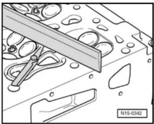
Fig. 1 Checking cylinder head for distortion
Special tools and equipment
♦ Straightedge
◆ Feeler gauge
Max. permissible distortion: 0.05 mm
15-10
natural_image
Mechanical assembly diagram showing gear and bracket components with two black arrows indicating specific parts (no text or symbols present)
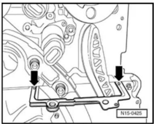
Fig. 2 Preparing cylinder head gasket for installation
Special tools and equipment
◆ AMV 174 004 01 Sealing compound
◆ AMV 188 001 02 Sealing compound
Work sequence
- Clean old sealing compound from 3 mm holes in cylinder head gasket (arrows).
- Fill 3 mm holes in cylinder head gasket with sealing compound AMV 174 004 01. Coat sealing surfaces on cover and seal flywheel/drive plate flange with sealing compound AMV 188 001 02. Install cover immediately.
Note:
When the cylinder head is installed the holes in the cylinder head gasket are only half visible.
15-11

Cover, removing and installing
1 - Cable guide
◆ For coolant hoses and wiring harness
◆ Coolant hose connection diagram ⇒ Page 19-11
2 - 8 Nm
3 - Camshaft Position (CMP) sensor 2-G163-
◆ For exhaust camshaft
Mark connector and component before disconnecting
◆ Checking:
⇒ Repair Manual, 2.8 Liter VR6 4V Fuel Injection & Ignition, Engine Code(s): BDF, Repair Group 01
4 - Chain tensioner, 40 Nm
◆ For camshaft roller chain ⇒ Page 15-4, item - 11 -
◆ Turn engine over only when chain tensioner is installed

15-12
5 - Seal
◆ Replace if damaged or leaking
6 - Cover
◆ Can be removed and installed with cylinder head fitted
◆ Coat sealing surfaces with sealing compound AMV 188 001 02
◆ With O-ring for sealing oil passage, item - 14
If only cover has been removed, prepare cylinder head gasket for assembly Page 15-10, Fig. 2
7 - 8 Nm
First
tighten
securing
bolts
(item - 9
-) to 23
Nm
15-13
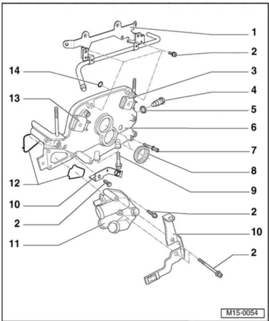
8 - Seal
◆ Valve -1-for camshaft adjustment -N205-, ⇒ Page 15-4, item -13 - and Camshaft adjustment valve 1 (exhaust) - N318-, ⇒ Page 15-5, item -14 -
◆ Replace if damaged or leaking
◆ Installing ⇒ Fig. 1
9 - 23 Nm
10 - Bracket
◆ For wiring harness
11 - Thermostat housing
◆ Disassembling and assembling ⇒ Page 19-13
◆ Coolant hose connection diagram ⇒ Page 19-11
12 - Seal
♦ Replace
15-14

13 - Camshaft Position (CMP) sensor - G40-
◆ For intake camshaft
Mark connector and component before disconnecting
◆ Checking:
⇒ Repair Manual, 2.8 Liter VR6 4V Fuel Injection & Ignition, Engine Code(s): BDF, Repair Group 01
14 - O-ring
◆ For oil channel seal
♦ Replace
♦ Lubricate before installing
15-15
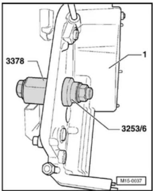

Fig. 1 Installing seals for cover
Special tools and equipment
◆ 3378 Puller sleeve
◆ 3253/6 Puller sleeve from fitting device 3253
Installing
Note:
Do not oil seal.
- Position seal in cover -1- using puller sleeve 3378 and pull in flush using puller sleeve 3253/6 from fitting device 3253.
15-16
T1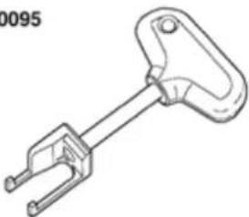 | V.A.G 1331 |
 | |
Cylinder head cover, removing and installing
Special tools and equipment
◆ T10095 Puller
◆ V.A.G 1331 Torque wrench (5...50 Nm)
◆ VAS 5024 Assembly tool for spring-type clips
◆ Cable tie
15-17
Removing
CAUTION!
When performing repair work, especially due to the confined conditions in the engine compartment, pay attention to the following:
Route all types of lines (e.g. for fuel, hydraulics, EVAP system, coolant, refrigerant, brake fluid and vacuum) as well as electrical wiring so that the original positions are restored.
- Ensure sufficient clearance to all moving or hot components.
Note:
All cable ties which are opened or cut open during disassembly, must be replaced in the same position during installation.
- Remove engine cover.
- Check whether a coded radio is installed. If so, obtain anti-theft coding.
- With ignition switched off disconnect battery Ground strap.
15-18


- Disconnect connectors from ignition coils 1...6.
Note:
Mark connector and component before disconnecting.
- Unclip ignition coils wiring harness from wiring guide.
- Remove ignition coils with final output stage for cylinders 1...6 using puller T10095.
- Pull off crankcase breather connecting hose between cylinder head cover and intake hose on cylinder head cover.
- Remove intake hose between Mass Air Flow (MAF) sensor and throttle valve control module:
⇒ Repair Manual, 2.8 Liter VR6 4V Fuel Injection & Ignition, Engine Code(s): BDF, Repair Group 24
Note:
Press buttons on hose couplings to do so.
15-19
natural_image
Technical line drawing of a mechanical assembly with hoses and a black arrow indicating a specific component (no text or symbols present)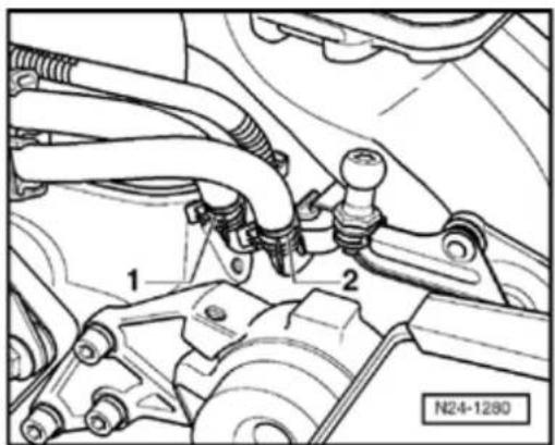

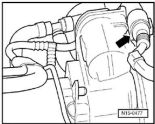
- Disconnect 6-pin connector from throttle valve control module (arrow).
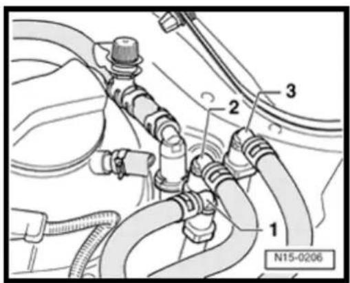
- O pen and close expansion tank cap to release pressure in cooling system.
- Pull coolant hoses off throttle valve control module and seal hose ends.

- Pull fuel supply hose -1- (with white marking) and fuel return hose -2- (with blue marking) off fuel rail and collect fuel that may leak out with a cloth.
WARNING!
Fuel system is under pressure! Before opening the system place a cloth around the connection. Then release pressure by carefully loosening the connection.
- Seal lines to avoid contamination of fuel system.
- O bserve rules for cleanliness Page 20-14.
15-20
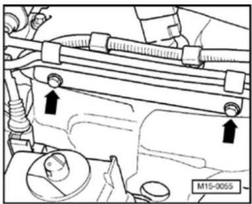
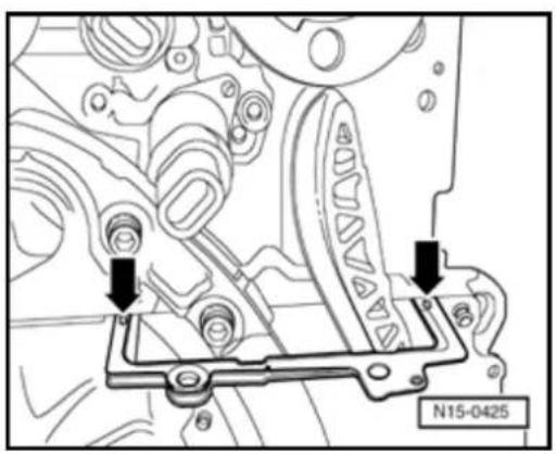
natural_image
Mechanical assembly diagram showing pipe connections and mounting features (no text or symbols)
- Remove retaining frame on cylinder head for fuel lines and wiring harness (arrows).
- Disconnect vacuum hoses (arrows) from intake manifold.
Note:
Press buttons on hose couplings to do so.
- Remove rearmost bolt -1- for intake manifold support.
- Unclip pressure hose (between combi-valve and secondary air pump motor) and all other lines from retainers on intake manifold and cylinder head cover.
- Remove guide on cover for coolant hoses and wiring harness Page 15-11, item - 1 -.
15-21
- Remove Ground connection on support of combi-valve Page 26-25, item - 9 -.
- Disconnect vacuum hose from variable intake manifold change-over vacuum actuator.
- Remove two lateral intake manifold support bolts.
- Remove center, left and right insulation trays:
⇒ Repair Manual, Body Exterior, Repair Group 50 - Disconnect connectors from thermal switch and coolant fan.
- Removing front bumper:
⇒ Repair Manual, Body Exterior, Repair Group 63 - Bring lock carrier into service position:
⇒ Repair Manual, Body Exterior, Repair Group 50 - Unscrew dipstick guide tube from intake manifold.
- Remove intake manifold securing bolts and remove intake manifold together with throttle valve control module.
15-22
- Remove intake manifold and place on a suitable surface so that vacuum actuator is not damaged.
Note:
Seal the intake ports in the intake manifold or in the cylinder head with a clean cloth.
- Remove cylinder head cover.
Installing
Install in reverse sequence ; note the following points:
Note:
◆ Replace cylinder head cover if damaged or leaking.
- First bolt intake manifold to cylinder head. Then tighten both bolts of the manifold support.
◆ Ensure tight fit of fuel hoses.
- If necessary replenish coolant Page 19-15.
- Check DTC memory:
⇒ Repair Manual, 2.8 Liter VR6 4V Fuel Injection & Ignition, Engine Code(s): BDF, Repair Group 01
15-23
- Adapting engine control module to throttle valve control module:
⇒ Repair Manual, 2.8 Liter VR6 4V Fuel Injection & Ignition, Engine Code(s): BDF, Repair Group 24 - Perform work sequence "Procedure after interrupting voltage supply":
⇒ Repair Manual, 2.8 Liter VR6 4V Fuel Injection & Ignition, Engine Code(s): BDF, Repair Group 24 - Read readiness code:
⇒ Repair Manual, 2.8 Liter VR6 4V Fuel Injection & Ignition, Engine Code(s): BDF, Repair Group 01 - If DTC memory has been erased or engine control module separated from permanent positive supply, readiness code must be generated again:
⇒ Repair Manual, 2.8 Liter VR6 4V Fuel Injection & Ignition, Engine Code(s): BDF, Repair Group 01
15-24
Torque settings
| Bolted connections | Torque setting |
| Cylinder head cover to cylinder head | 8 Nm |
| Intake manifold to cylinder head | 13 Nm |
| Intake manifold to support | 2 |
| Dipstick guide tube to intake manifold | 8 Nm |
3 Nm
15-25
 | V.A.G 1306 |
V.A.G 1331 | V.A.G 1332 |
 |
Cylinder head, removing and installing
Special tools and equipment
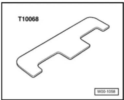
◆ T10068 Camshaft bar
◆ V.A.G 1306 Drip tray
◆ V.A.G 1331 Torque wrench (5...50 Nm)
◆ V.A.G 1332 Torque wrench (40...200 Nm)
◆ VAS 5024 Assembly tool for spring-type clips
◆ AMV 174 004 01 Sealing compound
◆ AMV 188 001 01 Sealing compound
15-26
Conditions
- The engine must only be warm to the touch.
Removing
CAUTION!
When performing repair work, especially due to the confined conditions in the engine compartment, pay attention to the following:
- Route all types of lines (e.g. for fuel, hydraulics, EVAP system, coolant, refrigerant, brake fluid and vacuum) as well as electrical wiring so that the original positions are restored.
- Ensure sufficient clearance to all moving or hot components.
Note:
All cable ties which are opened or cut open when removing engine, must be replaced in the same position when installing the engine.
- Remove engine cover.
- Check whether a coded radio is installed. If so, obtain anti-theft coding.
- With ignition switched off disconnect battery Ground strap.
15-27
natural_image
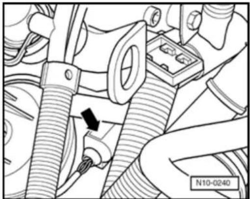
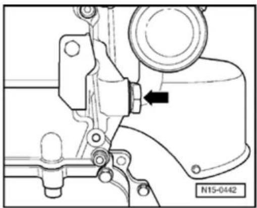
Mechanical assembly diagram showing hoses and components with a black arrow indicating a specific connection point (no text or symbols present)- Remove intake manifold Page 15-1,6 Removing and installing cylinder head co
- Disconnect 4-pin connector (arrow) from Coolant Temperature (ECT) sensor -G62 Engine Coolant Temperature sensor -G2
- Drain coolant Page 19-15.
- Remove coolant thermostat housing P 6, Parts of cooling system, engine side.
natural_image
Technical line drawing of a mechanical assembly with pulleys and gears (no text or symbols)- Turn crankshaft on vibration damper secu bolt in engine direction of rotation to TDC (arrow).
- Remove cylinder head cover Page 15.
15-28
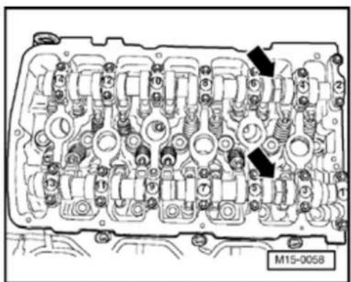
natural_image
Mechanical assembly diagram showing a valve or connector with a black arrow pointing to a component (no text or symbols present)
- Remove camshaft roller chain tensioner (arrow).
- Disconnect connections from following components on cover:
◆ Camshaft Position (CMP) sensor -G40--1-,
◆ Camshaft Position (CMP) sensor 2 -G163- -2-,
◆ Valve -1- for camshaft adjustment -N205- -3-,
◆ Camshaft adjustment valve 1 (exhaust) -N318- -4-.
Note:
Mark connector and component before disconnecting.
- Release and free wiring harness.
15-29

- Remove camshaft cover Page 15-11; Removing and installing camshaft.
- Mark roller chains before removing (e.g. v paint, arrow pointing in direction of rotation
Note:
Do not mark chain with a punched mark, no similar!
- Separate front exhaust pipe from exhaust manifold Page 26-1Removing and in parts of exhaust system.
- Check timing settings:
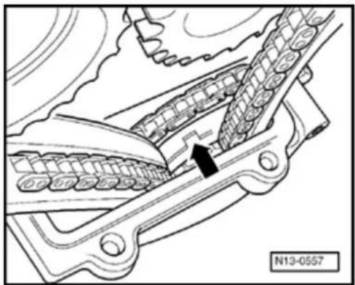
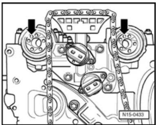
natural_image
Mechanical assembly diagram showing gear and shaft components with a black arrow indicating a specific part (no text or symbols present)When correctly positioned at TDC cyl. 1, groove (arrow) can be seen in intermedia chain sprockets
Note:
This condition only occurs at every 2nd TDU position.
15-30
If the notch cannot be seen:
- Turn crankshaft one full turn further in eng direction of rotation.
Note:
When the crankshaft is turned, the tensioning must be pressed against the camshaft roller chain by hand instead of with the chain tensioner.
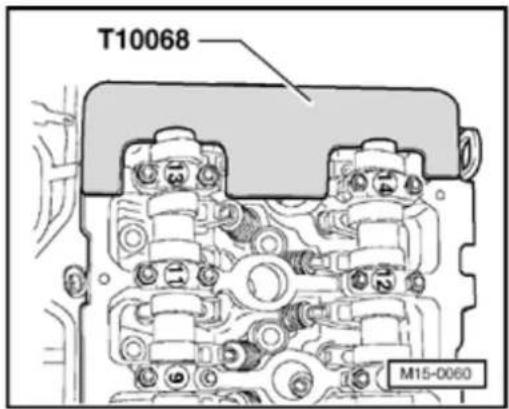
The camshaft bar T10068 must engage in shaft grooves.
Note:
If the camshaft bar cannot be installed, turn crankshaft in engine direction of rotation un approx. 5 mm past the TDC setting for No. (dependent on drive chain tolerances).
15-31
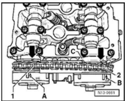
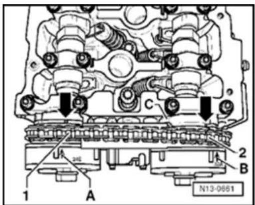
Check setting marks of camshaft timing adjusters with marks on control housing:

Marks -A and B- on camshaft timing adjusters must align with notches (arrows) on control housing -C-.
Distance between tooth -1- and tooth -2- of camshaft timing adjuster must be exactly 16 rollers of camshaft roller chain.
Note:
Illustration shows a cover which has been removed.
- First remove exhaust camshaft timing adjuster.
- Remove camshaft timing adjuster together with camshaft roller chain from intake camshaft.
Note:

Counter support on camshaft with a 32 mm open end wrench (arrow). Camshaft bar T10068 must not be installed when loosening or tightening camshaft timing adjuster.
15-32
- Remove guide rail securing bolts (arrow) and remove guide rail -1-.
- Place camshaft roller chain to side.
- L oosen socket head bolts in sequence given and then remove.
Note:
Use tool 3452 for Polydrive cylinder head bolts.
- Carefully lift cylinder head off.
15-33
Installing
- Place a clean cloth into cylinders so that or emery cloth particles can get in between cylinder wall and piston.
Note:
Also prevent dirt and emery cloth particles 1 getting into coolant.
- Carefully clean cylinder head and cylinder sealing surfaces. Ensure that no scoring scratches are formed (when using abrasive paper, grade must not be less than 100).
- Carefully remove metal particles, emery r and cleaning cloths.
If the piston for No. 1 cylinder is not at TDC
- Turn crankshaft on vibration damper secu bolt in engine direction of rotation (arrow)
natural_image
Technical line drawing of a mechanical assembly with pulleys and gears (no text or symbols)15-34
Note:
Only remove the new cylinder head gas, its packing immediately before installing.
◆ Handle the new gasket with extreme call Damage will lead to leaks.
- Install new cylinder head gasket. Inscripti (Part No.) must be legible.
- Ensure that dowel sleeves are inserted in cylinder block holes 12 and 20 and that c head gasket is seated.
Camshaft bar has been removed
- Position camshafts in cylinder head to TC 1 cylinder.
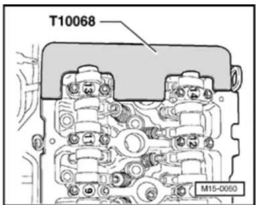
Camshaft bar T10068 must engage in bo grooves.
Note:
If the camshaft bar cannot be installed, turn over (in engine direction of rotation) past TL 1 and then turn back onto TDC No. 1 cyl.
15-35

natural_image
Mechanical assembly diagram showing gear and bracket components with two black arrows indicating specific parts (no text or symbols present)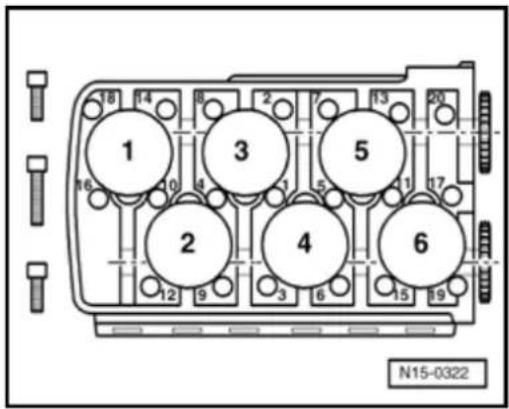

- F ill 3 mm holes in cylinder head gasket with sealing compound AMV 188 001 02.
Note:
When the cylinder head is installed the holes in the cylinder head gasket are only half visible.
- Install cylinder head, insert new cylinder head bolts and tighten by hand.

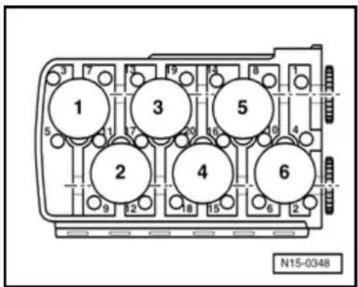
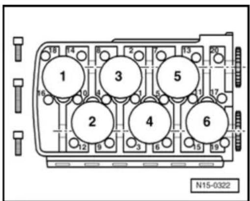
- Tighten cylinder head bolts in tightening sequence as follows:
Note:
The longer cylinder head bolts must be inserted in the middle holes of the cylinder head.
- Pretighten all bolts to 30 Nm.
- T hen tighten all bolts to 50 Nm.
- Then tighten all bolts ^1/_4 turn (90°) further with a rigid wrench.
- Then tighten all bolts again 14 turn (90 °) further.
15-36
The rest of the assembly is basically in reverse order to the disassembling sequence.
Note:
Ensure that the O-ring for sealing the oil channel and the seal in the cover are installed.
- Adjust valve timing Page 15-39.
- Install cylinder head cover and intake manifold Page 15-16; Removing and installing cylinder head.
- Fill with new coolant Page 19-15.
Note:
Re-tightening cylinder head bolts after repairs is not required.
- Check camshaft timing adjustments Page 15-82.
15-37
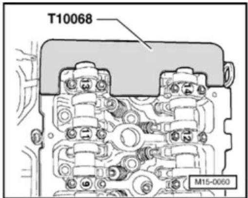
natural_image
3D mechanical part diagram labeled T10068 and W00-1058, no other text or symbols present
natural_image
Technical line drawing of a mechanical assembly with pulleys and gears (no text or symbols)Valve timing, checking
Special tools and equipment

◆ T10068 Camshaft bar
Test sequence
- Remove intake manifold and cylinder head cover Page 15-16; Removing and installing cylinder head.

- Turn crankshaft over on vibration damper securing bolt in engine direction of rotation (arrow).
15-38
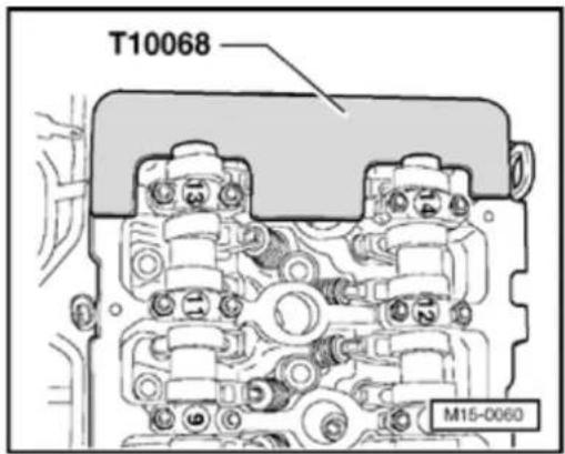


The camshaft bar T10068 must engage in both shaft grooves.
If the camshaft bar will not fit:
- Turn crankshaft one full turn further in engine direction of rotation.
Note:
If the camshaft bar cannot be installed, turn the crankshaft in engine direction of rotation until approx. 5 mm past the TDC setting for No. 1 cyl. (dependent on drive chain tolerances).
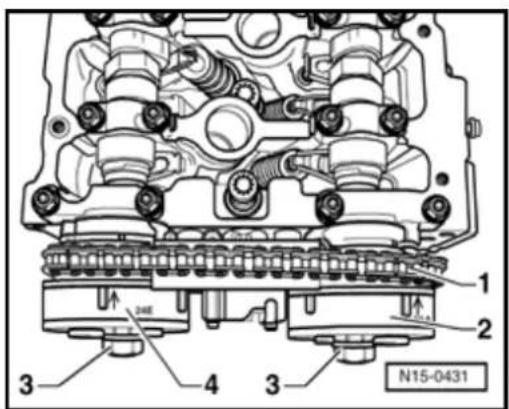
Check setting marks of camshaft timing adjusters with marks on control housing:

Marks -A and B- on camshaft timing adjusters must align with notches (arrows) on control housing -C-.
Distance between tooth -1- and tooth -2- of camshaft timing adjuster must be exactly 16 rollers of camshaft roller chain.
Note:
Illustration shows a cover which has been removed.
If the marks do not align:
- Adjust valve timing Page 15-39.
If the marks align:
- I install cylinder head cover and intake manifold Page 15-16; Removing and installing cylinder head.
15-39
 | T10069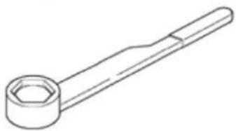 |
V.A.G 1331 | V.A.G 1332 |
W13-0107
Valve timing, adjusting
(Install timing chains)
Special tools and equipment
◆ T10068 Camshaft bar
◆ T10069 Counter support
◆ V.A.G 1331 Torque wrench (5...50 Nm)
◆ V.A.G 1332 Torque wrench (40...200 Nm)
◆ AMV 174 004 01 Sealing compound
◆ AMV 188 001 01 Sealing compound
15-40
Work sequence
CAUTION!
When performing repair work, especially due to the confined conditions in the engine compartment, pay attention to the following:
Route all types of lines (e.g. for fuel, hydraulics, EVAP system, coolant, refrigerant, brake fluid and vacuum) as well as electrical wiring so that the original positions are restored.
- Ensure sufficient clearance to all moving or hot components.
Note:
The following work sequence is described for an engine after removal. Start with the adjustments at the relevant position depending on how far the engine has been disassembled.
15-41

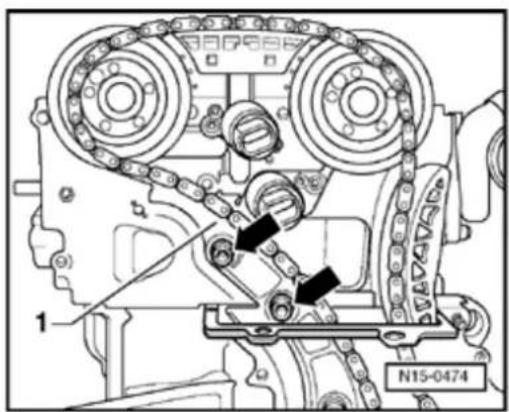
Install roller chain and chain tensioner with tensioning plate for intermediate shaft drive:

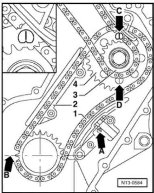
- Adjust position of crankshaft relative to intermediate shaft. To position: Align ground-down tooth of drive chain sprocket -B- with mounting joint (TDC cyl. 1).
- Install both bolts without collar for guide rail -2- and tighten to 10 Nm.
Note:
Observe direction of rotation marks of used roller chain Page 13-11, Fig. 1.
- Install guide rail -2- with roller chain -1- and both chain sprockets -3- and -4-.
Marking on sprocket -4- for roller chain must align with notch -C- or -D- on thrust washer of intermediate shaft.
During installation make sure that the roller chain runs completely straight in the guide plate from the crankshaft to the intermediate shaft.
15-42


- Tighten chain sprockets -3- and -4- on the intermediate shaft by hand.
Note:
Please observe that all chain sprocket securing screws/bolts must be replaced.
- Install chain tensioner on opposite side.
- Release locking splines of chain tensioner -A- with a small screwdriver and tensioning plate pressed against chain tensioner.
- Install chain tensioner in this position and tighten to 8 Nm.

- Lock vibration damper with counter support T10069.
15-43

natural_image
Technical diagram of an internal combustion engine cylinder head (no text or labels visible)
- Tighten new securing bolts of chain sprocket -3- and -4- for intermediate shaft to 60 Nm + 90° ( ^1/_4 turn - turning further can be done in several stages).
- Remove counter support T10069.
- Check position of crankshaft -B-to intermediate shaft -C- or -D-once again.
- Set engine again to TDC cyl. 1.
Install roller chain for camshaft drive:
- Position camshafts installed in cylinder head to TDC cylinder 1.
Note:

If necessary use 32 mm open end wrench to turn camshafts (arrows) to the correct position. The camshaft bar T10068 must not be installed when doing this.
15-44
natural_image
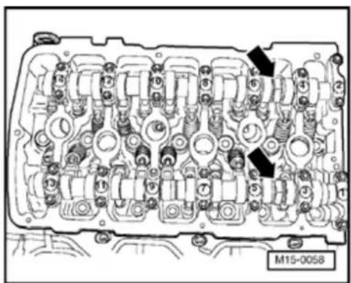
Mechanical assembly diagram showing components like gears and linkages with no visible text or symbols
It must be possible to insert camshaft bar T10068 into both shaft slots.
Note:
If the cylinder head is removed: Page 15-25, Removing and installing cylinder head.
- Place camshaft roller chain on intermediate shaft chain sprocket.
- Guide chain between tensioning rail and guide rail toward control housing.
- First install intake camshaft timing adjuster along with fitted camshaft roller chain.

- Position both camshaft timing adjusters (identification: 24E on intakeside and 32A on exhaust side) on the camshaft mountings (arrows).
15-45
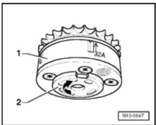
Note:
The exhaust camshaft timing adjuster -1- can be turned in two directions. When installing, ensure that the sensor wheel -2- for the CMP sensor -G163- is turned onto limit stop in direction of (arrow). The distance between the two ground-down teeth of the intake and exhaust camshaft timing adjusters (markings 24E and 32A) must be exactly 16 rollers of the camshaft roller chain
- Install exhaust camshaft timing adjuster with fitted camshaft roller chain.
Marks -A and B- on camshaft timing adjusters must align with notches (arrows) on control housing -C-.
- Tighten new securing bolts for camshaft timing adjuster hand tight.
- Check distance between tooth -1- and tooth -2- of camshaft timing adjuster. It must be exactly 16 rollers of camshaft roller chain.
- Remove camshaft bar T10068.
- Turn crankshaft two full turns in engine direction of rotation and check valve timing Page 15-37.
15-46
Note:
When the crankshaft is turned, the tensioning rail must be pressed against the camshaft roller chain by hand instead of with the chain tensioner.
If the marks do not align:
- Repeat timing adjustment.
If the marks align:


- Hold camshaft to be tightened with a 32 mm open end wrench (arrow).
Note:
The camshaft bar T10068 must not be installed when doing this.

- Tighten new securing bolts -3- for intake and exhaust camshaft timing adjusters -4 and 2- to 60 Nm + 90° ( ^1/_4 turn - turning further can be done in several stages).
- Coat sealing surfaces of flywheel/drive plate sealing flange with sealing compound AMV 188 001 02 and install. Tighten securing bolts to 8 Nm.
15-47
- Replace flywheel/drive plate sealing flang Page 13-24, item - 7 -.
- Remove old sealing compound from 3 mr in cylinder head gasket (arrows).
- Fill 3 mm holes in cylinder head gasket w sealing compound AMV 174 004 02.
Note:
When the cylinder head is installed the hole cylinder head gasket are only half visible.
- Coat sealing surface of cover with sealing compound AMV 188 001 02.
- L ubricate Oring for oil channel seal and i into cover together with seal ring.
- Install cover, insert all securing bolts and lightly.
- First tighten M8 securing bolt to 23 Nm th securing bolts to 8 Nm.
- Install chain tensioner for camshaft roller and tighten to 40 Nm.
- Turn crankshaft two full turns in engine di of rotation and check valve timing Pag 37.
- Install cylinder head cover and intake ma ⇒ Page 15-16, Removing and installing head
- Check camshaft adjustments Page 15
15-48
3122 B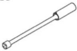 | T1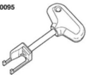 |
V.A.G 1331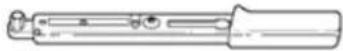 | V.A.G 1'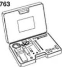 |
Compression pressure, checking
Special tools and equipment
◆ 3122 B Spark plug wrench
◆ T10095 Puller
◆ V.A.G 1331 Torque wrench (5...50 Nm)
◆ V.A.G 1763 Compression tester
15-49
Test conditions
- Engine oil temperature at least 30^ C
- The battery voltage must be at least 11.5 V.
- All electrical consumers, e.g. lights and rear window defroster must be switched off.
- If the vehicle is equipped with air conditioning, this must be switched off.
- On models with an automatic transmission selector lever in "P" or "N" position
Test sequence
- Remove fuse 29 from fuse holder.
Note:
Removing fuse 29 interrupts the voltage supply to the injectors.
- Remove engine cover.

15-50

- Disconnect connectors from ignition coils 1...6.
Note:
Mark connector and component before disconnecting.
- Remove ignition coils with final output stage for cylinders 1...6 using puller T10095.
- Remove spark plugs with spark plug wrench 3122 B.
- Have a second technician fully depress accelerator pedal.
- Check compression pressure with compression tester V.A.G 1763.
Note:
Using compression tester Operating instructions
- Operate starter until tester shows no further pressure increase.
15-51
Compression pressure values
New: 10...13 bar
Wear limit: 7.5 bar
Permissible difference between all cylinders: 3 bar
- Check DTC memory:
⇒ Repair Manual, 2.8 Liter VR6 4V Fuel Injection & Ignition, Engine Code(s): BDF, Repair Group 01 - Read readiness code:
⇒ Repair Manual, 2.8 Liter VR6 4V Fuel Injection & Ignition, Engine Code(s): BDF, Repair Group 01 - Generate readiness code again if DTC memory has been erased or engine control module separated from permanent positive supply:
⇒ Repair Manual, 2.8 Liter VR6 4V Fuel Injection & Ignition, Engine Code(s): BDF, Repair Group 01

Valve gear, servicing
1 - 5 Nm + 18 turn (45°) further
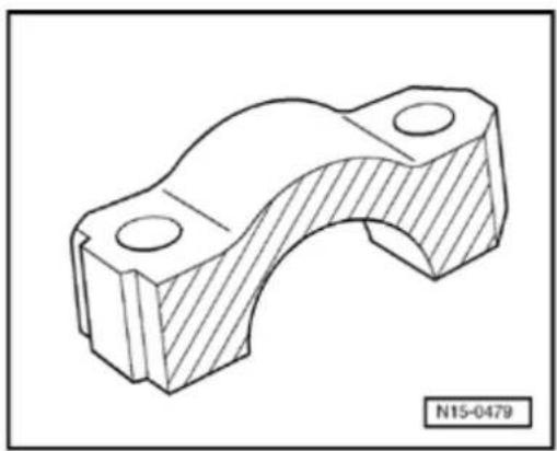
2 - Exhaust camshaft bearing cap
Before installing the bearing cap 8, grease lightly the contact surface with G 052 723 A2 ⇒ Fig. 2
◆ Installation position ⇒ Fig. 3
◆ Installation sequence ⇒ Page 15-69, Removing and installing camshaft
3 - Seal
◆ Replace complete if leaking
Oil contact surfaces of seal lightly when installing
control housing
◆ Spread/stretch seal as little as possible when replacing
♦ Offset gaps by 120°
15-53

4 - Exhaust camshaft
◆ Check radial clearance with Plastigage, Wear limit: 0.1 mm
◆ Run-out: max. 0.01 mm
◆ Checking axial clearance
⇒ Fig. 1
◆ Identification and valve timing ⇒ Fig. 5
♦ Removing and installing ⇒ Page 15-69
5 - Control housing
◆ Lightly lubricate contact surfaces of oil seal when installing
◆ Disassembling and assembling ⇒ Fig. 6
Check screen of control housing for soiling before
installing Fig. 7
♦ Removing and installing Page 15-69, Removing and installing camshaft
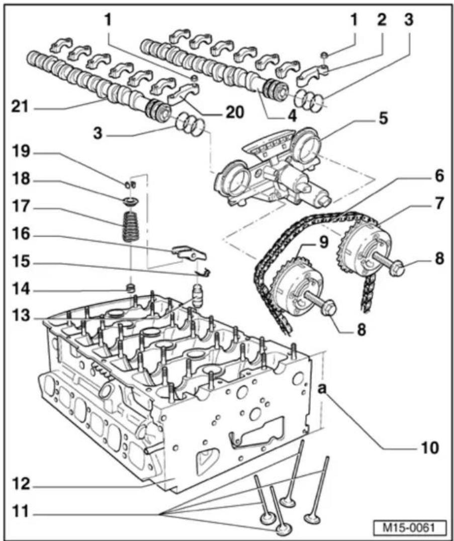
6 - Camshaft roller chain
Mark direction of rotation. before removing (installation position) ⇒ Page 13-11, Fig. 1
◆ Installing ⇒ Page 15-39, Adjusting valve timing
7 - Exhaust camshaft timing adjuster
◆ Marking: 32A
◆ Turn engine over only when camshaft timing adjuster is installed
◆ Checking camshaft timing adjustment ⇒ Page 15-82
◆ Installing ⇒ Page 15-39, Adjusting valve timing
8 - 60 Nm + 14 turn (90 °) further
◆ Replace
◆ Contact surface of sensor wheel on bolt head must be dry for assembly
To remove and install, use a 32 mm open end wrench on camshaft to counter-support → Page 15-69, Removing and installing camshaft
15-55

9 - Intake camshaft timing adjuster
◆ Markings: 24E
◆ Turn engine over only when camshaft timing adjuster is installed
◆ Checking camshaft timing adjustment ⇒ Page 15-82
◆ Installing ⇒ Page 15-39, Adjusting valve timing
10 - Cylinder head height
◆ Minimum height: a = 139.9 mm
11 - Valves
◆ Do not rework, only lapping-in is permitted
◆ Valve dimensions ⇒ Fig. 4
12 - Cylinder head
◆ Check for distortion Page 15-9, Fig. 1
♦ Removing and installing Page 15-25
◆ Reworking valve seats ⇒ Page 15-65
◆ After replacement replace the entire coolant

13 - Support element
◆ Check axial clearance of camshaft before installation ⇒ Fig. 1
◆ Do not interchange
◆ With hydraulic valve clearance compensation
14 - Valve stem seal
♦ Replacing ⇒ Page 15-92
15 - Retaining clip
◆ Check seated securely
16 - Roller rocker finger
◆ Check axial clearance of camshaft before installation ⇒ Fig. 1
- Do not interchange - Check roller bearing
for easy movement
◆ Oil running contact surfaces
◆ Use securing clip to clip onto support element when installing
15-57

17 - Valve spring
◆ Observe installation position
♦ Removing and installing ⇒ Page 15-92, Replacing valve stem seals
18 - Valve spring plate
19 - Valve cotters
20 Intake - camshaft bearing cap
Before installing bearing cap 7, lightly grease the contact surfaces with G 052 723 A2 ⇒ Fig. 2
◆ Installation position ⇒ Fig. 3
◆ Installation sequence → Page 15-69, Removing and
installing camshaft
15-58

21 - Intake camshaft
◆ Check radial clearance with Plastigage, Wear limit: 0.1 mm
◆ Run-out: max. 0.01 mm
◆ Checking axial clearance → Fig. 1
♦ Identification and valve timing ⇒ Fig. 5
♦ Removing and installing ⇒ Page 15-69
15-59
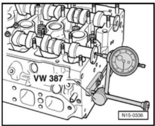

Fig. 1 Camshafts, checking axial clearance
Special tools and equipment
◆ VW 387 Universal dial gauge bracket
♦ Dial gauge
Test sequence
Perform measurements with support elements and roller rocker fingers removed.
Intake camshaft
- Install bearing cap 7 and tighten to 5 Nm and ^1/_8 turn (45°).
Wear limit: max. 0.10 mm
Exhaust camshaft
- Install bearing cap 8 and tighten to 5 Nm and ^1/_8 turn (45°).
Wear limit: max. 0.10 mm
15-60
natural_image
Technical drawing of a mechanical bracket component (no text or symbols)
Fig. 2 Greasing contact surfaces of bearing caps 7 and 8 lightly before installing
Special tools and equipment
◆ G 052 723 A2 Grease
Work sequence
- Before installing, lightly grease contact surfaces on both sides of bearing caps 7 and 8 (hatched areas only) with grease G 052 723 A2.
15-61


Fig. 3 Installation position of camshaft bearing caps
Points of bearing caps (arrow -A-) of intyake and exhaust camshafts face outward.
Identifications on bearing caps are legible when read from intake side.
15-62
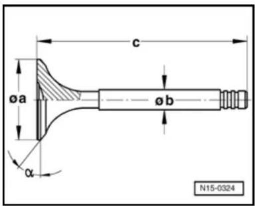

Fig. 4 Valve dimensions
Note:
Valves must not be reworked. Only lapping-in is permitted.
Valve dimensions for intake valves
| Dimension | Short intake valve | Long intake valve | |
| diameter a | mm | 3 1.00 | 3 1.00 |
| diameter b | mm | 5 .96 | 5 .96 |
| c | mm | 102.20 | 136.10 |
| ^ | 45 | 45 | |
Valve dimensions for exhaust valves
| Dimension | Short exhaust valve | Long exhaust valve | |
| diameter a | mm | 27.00 | 27.00 |
| diameter b | mm | 5.94 | 5.94 |
| c | mm | 102.50 | 136.40 |
| ^ | 45 | 45 | |
15-63
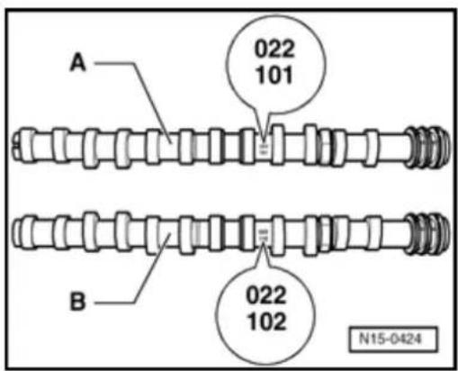

Fig. 5 Camshaft identification, valve timing
Camshaft identification
Identification between No. 4 cyl. and No. 5 cyl. cam pair of respective camshaft.
| Camshaft | Identification |
| A - Exhaust camshaft | 022101 Index |
| B - Intake camshaft | 022102 Index |
Valve timing at 1 mm valve lift
| Valve | Intake valve | Exhaust valve |
| Opens BTDC | --- | 211.5° |
| Closes BTDC | --- | 6.5° |
| Opens ATDC | 18.5° | --- |
| Closes ATDC | 223.5° | --- |
15-64
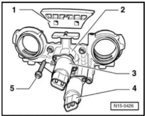
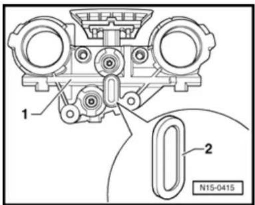

Fig. 6 Disassembling and assembling control housing
1 - Guide rail: Clipped onto control housing
2 - Control housing:
Replaced complete with Valve -1- for camshaft adjustment -N205- and Camshaft adjustment valve 1 (exhaust) -N318-.
3 - Valve -1- for camshaft adjustment -N205-
4 - Camshaft adjustment valve 1 (exhaust) -N318-
5 - 8 Nm: Replace (4 securing bolts)

Fig. 7 Checking control housing screen for soiling
- Unclip screen -2- out from rear side of control housing -1- and clean if necessary.
15-65
Valve seats, reworking
Special tools and equipment
♦ Depth gauge
◆ Valve seat refacing tool
Work sequence
Note:
When repairing engines with leaking valves, it is not sufficient to rework or replace valve seats and valves. It is also necessary to check the valve guides for wear. This is particularly important on high mileage engines Page 15-91.
The valve seats should only be reworked just enough to produce a perfect seating pattern. The maximum permissible reworking dimension must be calculated before reworking commences. If the reworking dimension is exceeded, the function of the hydraulic lifters can no longer be guaranteed and the cylinder head should be replaced.
- Remove camshafts Page 15-69.
15-66
The maximum permissible reworking dimension is calculated as follows:
- I insert valve and press firmly against seat.
Note:
If the valve is to be replaced as part of a repair, use a new valve for the measuring.
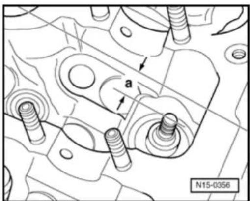
natural_image
Technical line drawing of a mechanical assembly with bolts and a labeled dimension 'a', no readable text or symbols present.
- Measure distance -a- between end of valve stem and upper edge of cylinder head.
- Calculate max. permissible reworking dimension from measured distance -a- and minimum dimension.
Minimum dimensions
| Short intake valve | m | m 3 1.8 |
| Long intake valve | mm | 10.2 |
| Short exhaust valve | m m | 3 1.8 |
| Long exhaust valve | mm | 10.2 |
Measured distance minus minimum dimension = Max. permissible reworking dimension.
15-67
Example:
| - | Measured distanceMinimum dimension | 10.610.2 | mmmm |
| = | Max. perm.rework dimension* | 0.4 | m m |
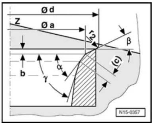
*) The max. permissible reworking dimension is shown as dimension "b" in illustrations for the reworking of valve seats.
Reworking intake valve seat
a = Diameter 30.6 mm
b = Max. permissible reworking dimension*
c = 0.9...1.5 mm
d = Max. diameter 35.0 mm
r_2 = Radius 2.0 mm
Z = Lower edge of cylinder head
α = 45 ° valve seat angle
β = 30 ° u pper correction angle
= 60 ° lower correction angle
*) How to calculate the max.
permissible reworking dimension Page 15-66.
15-68
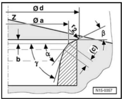
◀ Reworking exhaust valve seat
a = Diameter 26.7 mm
b = Max. permissible reworking dimension*
c = 1.2...1.7 mm
d = Max. diameter 29.0 mm
r₂ = Radius 2.0 mm
Z = Lower edge of cylinder head
α = 45 ° valve seat angle
β = 30 ° u pper correction angle
γ = 60 ° lower correction angle
*) How to calculate the max.
permissible reworking dimension Page 15-66.
15-69
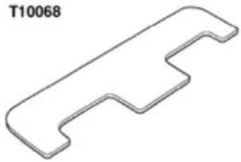 | V.A.G 1331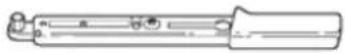 |
V.A.G 1332 | |
Camshafts, removing and installing
(with cylinder head installed)
Special tools and equipment
◆ T10068 Camshaft bar
◆ V.A.G
1331
Torque
wrench
(5...50
Nm)
◆ V.A.G
1332
Torque
wrench
(40...200
Nm)
◆ AMV 174
004 01
Sealing
compound
◆ AMV 188
001 02
Sealing
compound
◆ G 052 723
A2 Grease
15-70
Removing
CAUTION!
When performing repair work, especially due to the confined conditions in the engine compartment, pay attention to the following:
Route all types of lines (e.g. for fuel, hydraulics, EVAP system, coolant, refrigerant, brake fluid and vacuum) as well as electrical wiring so that the original positions are restored.
- Ensure sufficient clearance to all moving or hot components.
Note:
All cable ties which are opened or cut open during disassembly, must be replaced in the same position during installation.
- Remove engine cover.
- Check whether a coded radio is installed. If so, obtain anti-theft coding.
- With ignition switched off disconnect battery Ground strap.
- Remove intake manifold Page 15-16, Removing and installing cylinder head cover.
15-71
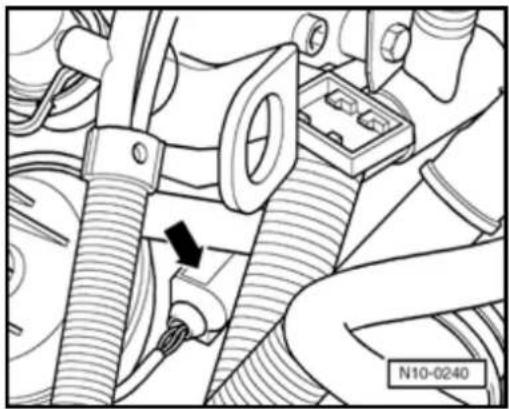
natural_image
Mechanical assembly diagram showing hoses and components with a black arrow indicating a specific connection point (no text or symbols present)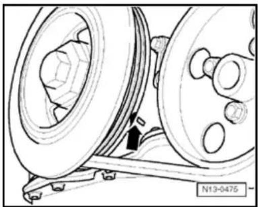
natural_image
Technical line drawing of a mechanical assembly with pulleys and gears (no text or symbols)
- Disconnect 4-pin connector (arrow) from Engine Coolant Temperature (ECT) sensor -G62-with Engine Coolant Temperature (ECT) sensor -G2-.
- Drain coolant Page 19-15.
- Remove coolant thermostat housing Page 19-6, Parts of cooling system, engine side.

- Set crankshaft to TDC No. 1 Cyl. marks (arrow) by turning crankshaft on vibration damper securing bolt in engine direction of rotation.
- Remove cylinder head cover Page 15-16.
15-72

natural_image
Mechanical assembly diagram showing a valve or connector with a black arrow pointing to a component (no text or symbols present)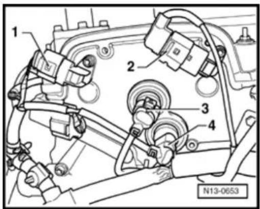
- Remove camshaft roller chain tensioner (arrow).
- Disconnect connections from following components on cover:
◆ Camshaft Position (CMP) sensor -G40--1-,
◆ Camshaft Position (CMP) sensor 2 -G163- -2-,
◆ Valve -1- for camshaft adjustment -N205- -3-,
◆ Camshaft adjustment valve 1 -N318- -4-.
Note:
Mark connector and component before disconnecting.
- Release and free wiring harness.
15-73
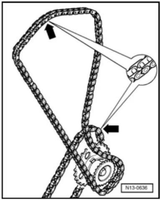
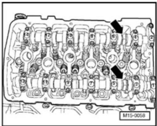
natural_image
Technical diagram of an internal combustion engine cylinder head (no text or labels visible)- Remove camshaft cover Page 15-11, Removing and installing camshaft.
- Mark roller chains before removing (e.g. v paint, arrow pointing in direction of rotation
Note:
Do not mark chain with a punched mark, no similar!
- First remove exhaust camshaft timing adj
- Remove camshaft timing adjuster together, camshaft roller chain from intake camsha
Note:
Counter-support on camshaft with a 32 mm end wrench (arrow). Camshaft bar T10068 not be installed when loosening or tighten in camshaft timing adjuster.
- Place camshaft roller chain to side.
15-74
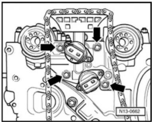
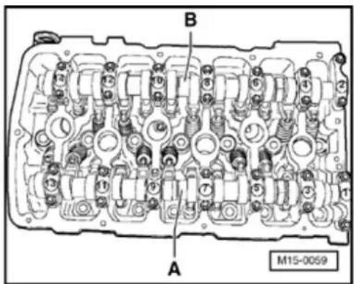
- Remove control housing from cylinder head (arrows).
- Pull control housing carefully of camshaft seals.
A - Intake camshaft
- First remove bearing caps 1 and 13.
- Remove bearing caps 3 and 11.
- Remove bearing cap 7.
- L oosen bearing caps 5 and 9 alternately and diagonally, and remove.
15-75
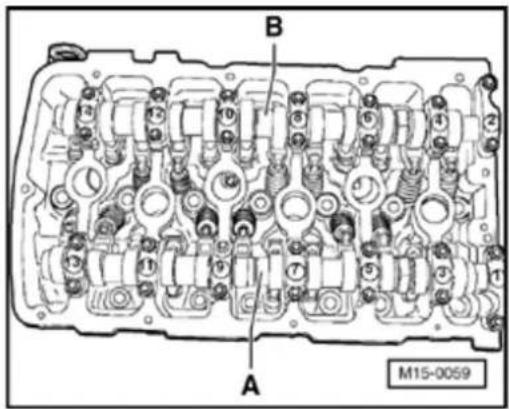
B - Exhaust camshaft
- First remove bearing caps 2 and 14.
- Remove bearing caps 4 and 12.
- Remove bearing cap 8.
- Loosen bearing caps 6 and 10 alternately and diagonally.
- Carefully remove camshafts and place on a clean surface.
- Remove roller rocker finger together with support elements and place on a clean surface.
Note:
Ensure the roller rocker fingers and the support elements are not interchanged.
15-76
Installing
Conditions
- When camshafts are installed, No. 1 Cy cams must point upward.
- Pistons must not be positioned at TDC.
- Insert support element in cylinder head and roller rocker finger onto respective valve s end / support element.
- Ensure that all roller rocker fingers -1- are properly installed onto valve stem ends a clipped onto respective support elements
- Oil running surfaces of camshafts.
- Place respective camshaft carefully into camshaft bearings in cylinder head. Obse marks on camshafts Page 15-63, F
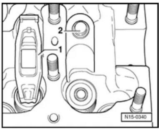
15-77
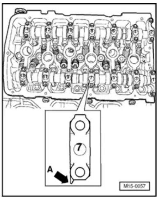
Note:
< Observe installation position of bearing caps:
◆ Points of bearing caps (arrow -A-) of intake and exhaust camshafts face outward.
◆ Identifications on bearing caps are legible when read from intake side.
15-78

A - Intake camshaft
- Lubricate hatched contact surface of bearing cap 7 from both sides lightly with grease G 052 723 A2 before installation Page 15-6,0 Fig. 2.
- Tighten bearing caps 5 and 9 alternately and diagonally to 5 Nm and ^1/_8 turn (45°).
- Install bearing caps 1 and 13 and tighten to 5 Nm and ^1/_8 turn (45°).
- Install bearing cap 7 and tighten to 5 Nm and ^1/_8 turn (45°).
- Install bearing caps 3 and 11 and tighten to 5 Nm and ^1/_8 turn (45°).
15-79
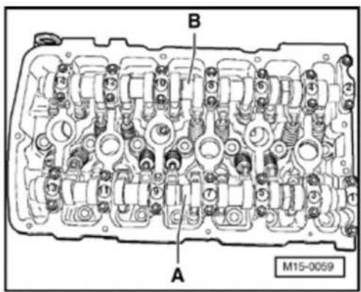
B - Exhaust camshaft
- Lubricate hatched contact surface of bearing cap 8 from both sides lightly with grease G 052 723 A2 before installation Page 15-6,0 Fig. 2.
- Tighten bearing caps 6 and 10 alternately and diagonally to 5 Nm and ^1/_8 turn (45°).
- Install bearing caps 2 and 14 and tighten to 5 Nm and ^1/_8 turn (45°).
- Install bearing cap 8 and tighten to 5 Nm and 1/8 turn (45°).
- Install bearing caps 4 and 12 and tighten to 5 Nm and ^1/_8 turn (45°).
15-80
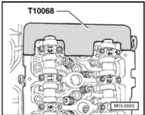
- Position camshafts in cylinder head to TE 1 cylinder.
Camshaft bar T10068 must engage in bo grooves.
Note:
If the camshaft bar cannot be engaged in the camshafts, turn camshafts in direction of ro past TDC No. 1 Cyl. and then back to TDC Cyl.
- Before installing, check screen in control housing for soiling Page 15-64, Fig
- Before installing control housing, lightly lu contact surfaces in control housing for ca seals.
- Lubricate contact surfaces of camshaft set lightly and slowly push control housing on camshaft seals.
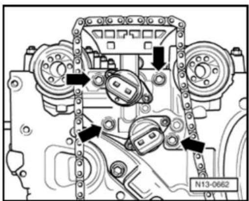
- Install control housing (arrows) and tighted Nm.
15-81

natural_image
Mechanical assembly diagram showing gear and mounting bracket components with two black arrows indicating features (no text or symbols present)
- Remove old sealing compound from 3 mm holes in cylinder head gasket (arrows).
Note:
When the cylinder head is installed the holes in the cylinder head gasket are only half visible.
The rest of the assembly is basically in reverse order to the disassembling sequence.
Note:
Ensure that the O-ring for sealing the oil channel and the seal in the cover are installed.
- Adjust valve timing Page 15-39.
- Install cylinder head cover and intake manifold Page 15-16, Removing and installing cylinder head
- Check camshaft adjustments Page 15-82.
15-82
Camshaft adjustment, checking
Function
The camshaft timing adjustment is dependent upon load and speed. Oil pressure is directed to the camshaft timing adjuster (mechanical adjustment unit) by the camshaft timing adjustment solenoid valve and the camshaft adjuster then adjusts the camshaft.
Special tools and equipment
◆ V.A.G 1551 Scan Tool (or vehicle system tester V.A.G 1552) with cable V.A.G 1551/3
Note:
All functions which could previously be performed with V.A.G 1551/1552 can also be performed with the new tester VAS 5051.
15-83

Test conditions

- Fuses must be OK.
- Battery voltage must be at least 11.5 V.
- All electrical consumers, e.g. lights and rear window defroster must be switched off.
- If the vehicle is equipped with air conditioning, this must be switched off.
- Selector lever must be in position "P" or "N" on vehicles with an automatic transmission.
- Engine oil level OK, checking ⇒ Page 17-8, Fig. 2
- No DTCs may be stored in the DTC memory:
⇒ Repair Manual, 2.8 Liter VR6 4V Fuel Injection & Ignition, Engine Code(s): BDF, Repair Group 01
Checking activation
- Check Valve -1- for camshaft adjustment -N205- and Camshaft adjuster valve 1 (exhaust) -N318- via output Diagnostic Test Mode (DTM):
⇒ Repair Manual, 2.8 Liter VR6 4V Fuel Injection & Ignition, Engine Code(s): BDF, Repair Group 01
15-84
If activation is OK.:
Checking function of camshaft timing adjuster
Test conditions
- Coolant temperature must be at least 85 °C,⇒display group 1, display zone 2.
Test sequence
- Connect V.A.G 1551 Scan Tool (or V.A.G 1552). Start engine and select "Address word" 01 of engine control module. Connect Scan Tool and select engine control module:
⇒ Repair Manual, 2.8 Liter VR6 4V Fuel Injection & Ignition, Engine Code(s): BDF, Repair Group 01
Rapid data transfer
HELP

Indicated on display
Select function XX
- Press keys 0 and 4 for function "Initiate basic setting" and confirm entry with Q key.
Basic setting

Indicated on display
Input display group number XXX
- Press keys 0, 0 and 1 for "Display group number 1" and confirm entry with Q key.
15-85
| System in basic setting 1 | → | ||
| 1 | 2 | 3 | 4 |
Basic setting
Input display group number XXX
| System in basic setting 94 | → | ||
| 1 | 2 | 3 | |
< Indicated on display: (1...4 = display zones)
Only continue with the test when:
- Coolant temperature is above 85 °C -Display zone 2-
Checking intake camshaft timing adjustment
- Change to display group 94 as follows:
- Press C key.
< Indicated on display
- Press keys 0, 9 and 4 for "Display group number 94" and confirm entry with Q key.
< Indicated on display: (1...3 = display zones)
- Depress brake pedal and hold.
- Depress accelerator down to wide open throttle position.
Engine speed will be increased by engine control module to approx. 2300 rpm.
15-86
- Hold brake pedal and accelerator down until display in display zone 3 jumps from "Test OFF" to "Test ON".
- Continue to hold brake pedal and accelerator down until display zone 3 displays specification "Syst. OK.".
- Release brake and accelerator pedals.
If "Syst.n.OK." appears in display zone 3:
- Press → key.
- Check DTC memory:
⇒ Repair Manual, 2.8 Liter VR6 4V Fuel Injection & Ignition, Engine Code(s): BDF, Repair Group 01
- Read readiness code:
⇒ Repair Manual, 2.8 Liter VR6 4V Fuel Injection & Ignition, Engine Code(s): BDF, Repair Group 01
- Generate readiness code again if DTC memory has been erased or engine control module separated from permanent positive supply:
⇒ Repair Manual, 2.8 Liter VR6 4V Fuel Injection & Ignition, Engine Code(s): BDF, Repair Group 01
15-87
If no DTC is stored in DTC memory:
- Press keys 0 and 6 for function "End output" and confirm entry with Q key.
- Switch ignition off.
- Check Camshaft Position (CMP) sensors -G40- and -G163- (connections may be interchanged):
⇒ Repair Manual, 2.8 Liter VR6 4V Fuel Injection & Ignition, Engine Code(s): BDF, Repair Group 28
- Check oil pressure Page 17-19, Checking oil pressure and oil pressure switch.
- Check valve timing Page 15-37.
When no faults can be located:
- Replace intake camshaft timing adjuster Page 15-69, Removing and installing camshaft
If "Sys. OK." appears in display zone 3:
15-88
Basic setting
Input display group number XXX
System in basic setting 96
1
2

3
Check exhaust camshaft timing adjustment
- Change to display group 96 as follows:
- Press C key.
< Indicated on display
- Press keys 0, 9 and 6 for "Display group number 96" and confirm entry with Q key.
< Indicated on display: (1...3 = display zones)
- Depress brake pedal and hold.
- Depress accelerator down to wide open throttle position.
Engine speed will be increased by engine control module to approx. 2300 rpm. - Hold brake pedal and accelerator down until display in display zone 3 jumps from "Test OFF" to "Test ON".
- Continue to hold brake pedal and accelerator down until display zone 3 displays specification "Syst. OK.".
15-89
- Release brake and accelerator pedals.
If "Sys. OK." appears in display zone 3: - Presskey.
- Press keys 0 and 6 for function "End output" and confirm entry with Q key.
- Switch ignition off.
If "Syst.n.OK." appears in display zone 3:
- Press → key.
- Check DTC memory:
⇒ Repair Manual, 2.8 Liter VR6 4V Fuel Injection & Ignition, Engine Code(s): BDF, Repair Group 01
- Read readiness code:
⇒ Repair Manual, 2.8 Liter VR6 4V Fuel Injection & Ignition, Engine Code(s): BDF, Repair Group 01
- Generate readiness code again if DTC memory has been erased or engine control module separated from permanent positive supply:
⇒ Repair Manual, 2.8 Liter VR6 4V Fuel Injection & Ignition, Engine Code(s): BDF, Repair Group 01
15-90
If no DTC is stored in DTC memory:
- Press keys 0 and 6 for function "End output" and confirm entry with Q key.
- Switch ignition off.
- Check Camshaft Position (CMP) sensors -G40- and -G163- (connections may be interchanged):
⇒ Repair Manual, 2.8 Liter VR6 4V Fuel Injection & Ignition, Engine Code(s): BDF, Repair Group 28
- Check oil pressure Page 17-19, Checking oil pressure and oil pressure switch.
- Check valve timing Page 15-37.
When no faults can be located:
- Replace exhaust camshaft timing adjuster Page 15-69, Removing and installing camshaft
15-91
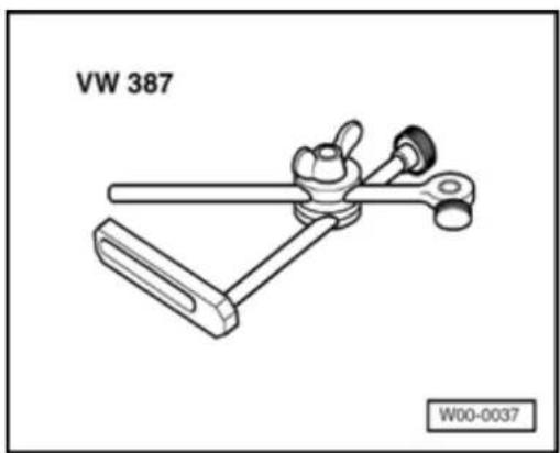
natural_image
Technical line drawing of a mechanical clamp or lever assembly (no text or symbols on the diagram itself)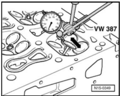
Valve guides, checking
Special tools and equipment

◆ VW 387 Universal dial gauge bracket
♦ Dial gauge
Test sequence

- Insert a new valve into guide.
Note:
The end of the valve stem must be flush with the guide. Due to the slight difference in stem diameters, ensure that only an intake valve is used in the intake guide and an exhaust valve in the exhaust guide.
- Determine rock.
Wear limit: 0.8 mm
If rock tolerance is exceeded:
- Replace cylinder head.
15-92
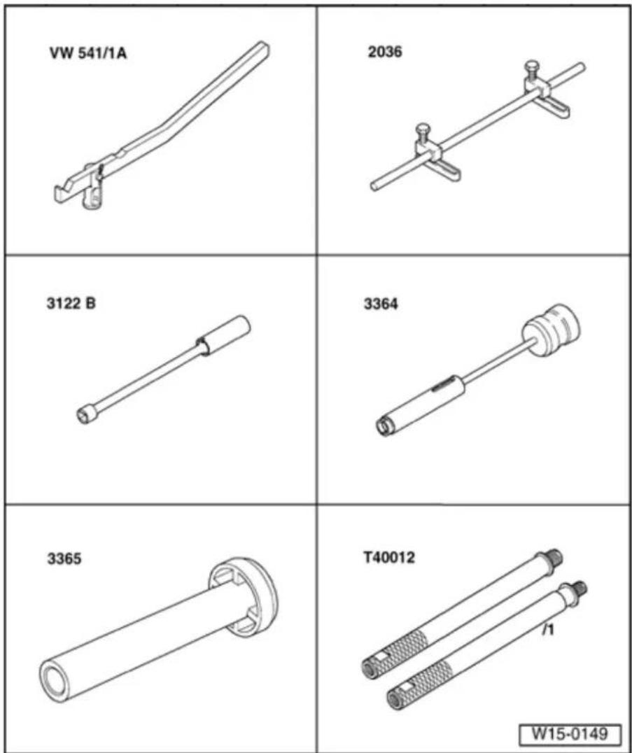
Valve stem seals, replacing
(with cylinder head installed)
Special tools and equipment
◆ VW
541/1A
Assembly
lever with
press
piece VW
541/6
◆ 2036 Assembly tool with adapter plate 2036/1
◆ 3122 B Spark plug wrench
◆ 3364 Puller
◆ 3365
Installation tool
◆ T40012 Adapter
15-93
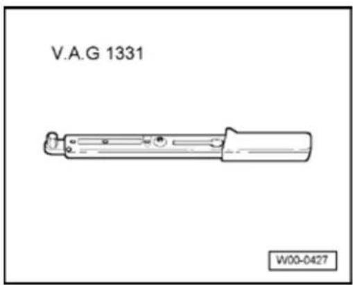
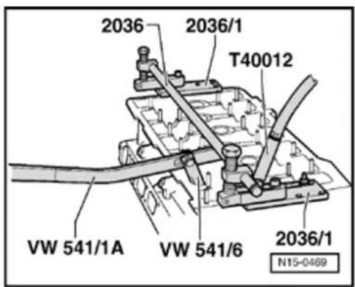

◆ V.A.G 1331 Torque wrench (5...50 Nm)
Removing
- Remove camshafts Page 15-69.
- Remove roller rocker finger together with support elements and place on a clean surface.
Note:
Ensure the roller rocker fingers and the support elements are not interchanged.
- Remove spark plugs with spark plug wrench 3122B.
- Set piston of corresponding cylinder to "bottom dead center".

- F it assembly appliance 2036 with adapter plates 2036/1 and adjust mountings.
- Screw adapter T40012 into threaded hole for spark plug and apply a continuous pressure of at less 6 bar
- Remove valve springs with assembly lever VW 541/1A and thrust piece VW 541/6.
Note:
Tight cotters can be loosened by tapping lightly on the lever with a hammer.
15-94
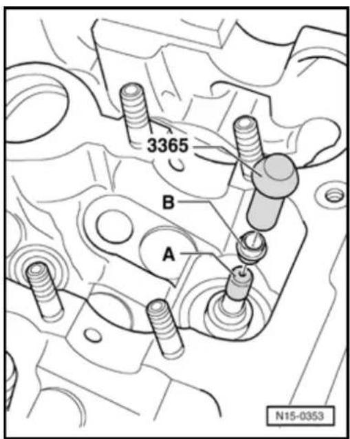
- Pull off valve stem seals with puller 3364.
Installing

- Prevent damage to new valve stem seals by sliding plastic sleeve -A- over valve stem.
- Oil sealing lip of valve stem seal - B-insert in fitting tool 3365 and carefully push onto valve guide.
- Install camshafts Page 15-69.
Lubrication system components, servicing
Note:
When working on the engine it should be secured to assembly stand VW 313 using engine bracket 3269 or VW 540 and supplementary set 540/1 B.
The oil level must not be above the max. mark - danger of damage to catalytic converter! Marks Page 17-8, Fig. 2.
If, when repairing an engine, metal shavings or large amounts of small metal particles are found in the engine oil, caused for example by partial seizure of crankshaft or conrod bearings, perform the following work sequences to prevent consequential damage once repairs are complete:
-- Thoroughly clean oil passages
-- Replace oil spray jets
-- Replace oil cooler
-- Replace oil filter
-- Replace oil non-return valve
Disassembling and assembling oil filter housing Page 17-9.
Disassembling and assembling oil pump Page 17-12.
Checking oil pressure and oil pressure switch Page 17-19.
Oil system capacity
⇒ Fluid Capacity Chart
Engine oil specifications
New VW standard (specially developed, age resistant)
Initial filling: VW standard: 503 00 (VW TL 52 173)
Note:
In the factory the engine is filled with engine oil according to VW standard 503 00. This engine oil is adjusted for long service intervals (ESI). However, you can also use the engine oils listed below.
Use engine oils according to VW standard 500 00, 501 01 or 502 00. Multi-grade oils corresponding to API-SJ or SL are also acceptable.
17-3
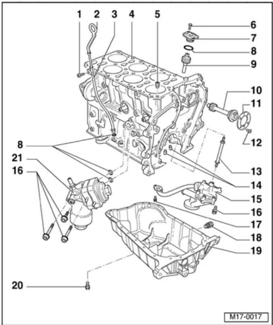
1 - 8 Nm
◆ Secured to intake manifold
2 - Dipstick
◆ Oil level must not exceed the max. mark!
◆ Markings ⇒ Fig. 2
3 - Guide tube
◆ For dipstick
◆ Secured by a bolt to intake manifold
4 - Cylinder block
♦ Removing and installing sealing flange and dual-mass flywheel ⇒ Page 13-22
♦ Removing and installing crankshaft → Page 13-34
♦ Disassembling and assembling piston and conrod ⇒ Page 13-39
17-4

5 - Oil non-return valve, 5 Nm
◆ Observe installation position
◆ Clean if badly soiled
◆ See
note ⇒
Page
17-1
6 - 10 Nm
7 - Oil pump
drive
cover
8 - O-ring
♦ Replace
♦ Lubricate before installing
9 - Oil pump drive
10 Intermediate - shaft
11 - Thrust washer
12 - 10 Nm
◆ Install with locking compound D 000 600 A2

13 - Drive shaft
◆ For oil pump drive
14 - Oil spray jet
◆ For crankshaft bearings 2...7
◆ For piston cooling
◆ Opening pressure: 2.0 bar
♦ Removing and installing ⇒ Fig. 1
◆ See note ⇒ Page 17-1
15 - Oil pump
◆ Disassembling and assembling ⇒ Page 17-12
◆ Coat oil pressure pipe with sealing compound AMV 188 001 02 at cylinder block and oil pump housing
16 - 23 Nm
17 - 8 Nm
◆ Insert with
locking
compound
D 000 600
A2
17-6

18 - Oil drain plug, 30 Nm
◆ Replace if leaking
19 - Oil pan
♦ Removing and installing ⇒ Page 17-15
20 - 12 Nm
21 - Oil filter housing
◆ See note ⇒ Page 17-1
◆ Disassembling and assembling ⇒ Page 17-9
◆ Coolant hose connection diagram ⇒ Page 19-11
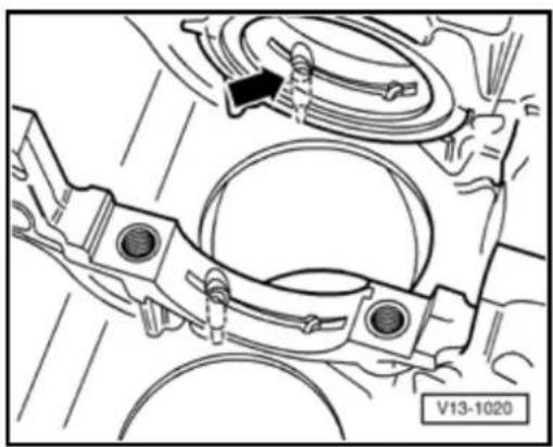
natural_image
Technical line drawing of a mechanical assembly with no visible text or symbols
Fig. 1 Removing and installing oil spray jet
Special tools and equipment
◆ 4 mm diameter drift
◆ 6 mm diameter drift
Note:
Oil spray jets are installed in main bearings 2....7.
Removing
- Press oil spray jet out toward bearing using a 4 mm diameter drift.
Installing
- To install, press oil spray jet in by hand using a 6 mm diameter drift (arrow).
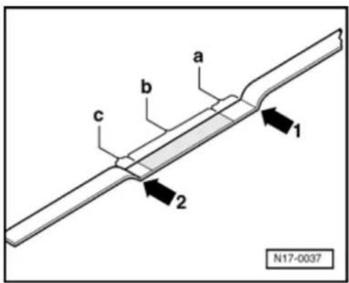

Fig. 2 Dipstick markings
1 - Max. mark
2 - Min. mark
a - Area above hatched field up to max. mark: Do not replenish engine oil!
b - Oil level within hatched field: Engine oil may be replenished
c - Area from min. mark up to hatched field: Replenish with max. 0.5 liters of engine oil!
17-9

Oil filter housing, disassembling and assembling
1 - Sealing plug, 10 Nm
◆ If seal is leaking nip open and replace.
2 - 1.4 bar Oil pressure switch - F1-, 20 Nm
◆ Marking: black
◆ If seal is leaking nip open and replace.
◆ Checking ⇒ Page 17-19
3 - Oil filter housing
With non-return valve, Opening pressure: 0.05 bar
4 - O-ring
♦ Replace
♦ Lubricate before installing

17-10
5 - Oil cooler
◆ Ensure clearance to adjacent components
◆ Coat contact area outside seal with sealing compound AMV 188 001 02
◆ See Note ⇒ Page 17-1
◆ Coolant hose connection diagram ⇒ Page 19-11
6 - Seal
◆ Replace
♦ Lubricate before installing
7 - Oil cooler cover, 25 Nm
8 - O-ring
◆ Replace
♦ Lubricate before installing
◆ Insert into oil
cooler
before
installing
oil
cooler
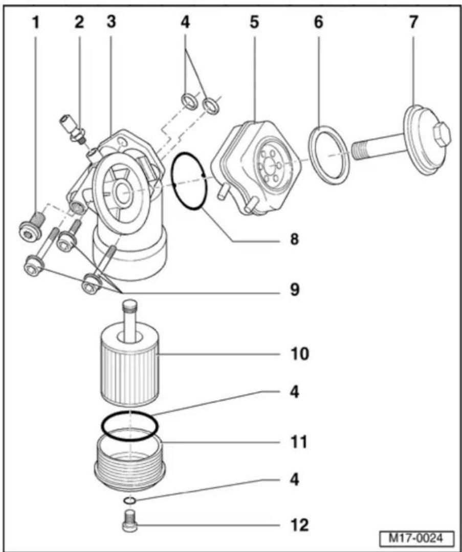
17-11
9 - 23 Nm
10 - Oil filter element
◆ Observe change intervals
◆ See Note ⇒ Page 17-1
11 - Oil filter lower part, 25 Nm
- Drain before removing
◆ With bypass valve, Opening pressure: 2.50 bar
12 - Oil drain plug, 10 Nm
17-12
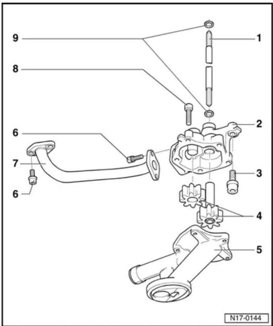
Oil pump, disassembling and assembling
1 - Drive shaft
◆ For oil pump drive
2 - Oil pump housing
3 - 23 Nm
4 - Gears
◆ Checking backlash ⇒ Fig. 1
◆ Checking axial clearance ⇒ Fig. 2
5 - Oil pump cover with pressure relief valve
◆ Clean strainer if soiled
◆ Opening pressure: 5.3...5.7 bar
6 - 8 Nm
◆ Insert with locking compound D 000 600 A2

17-13
7 - Oil pressure pipe
◆ Coat cylinder block and oil pump housing with sealing compound AMV 188 001 02
8 - 8 Nm
9 - Seal
◆ Replace if damaged
17-14
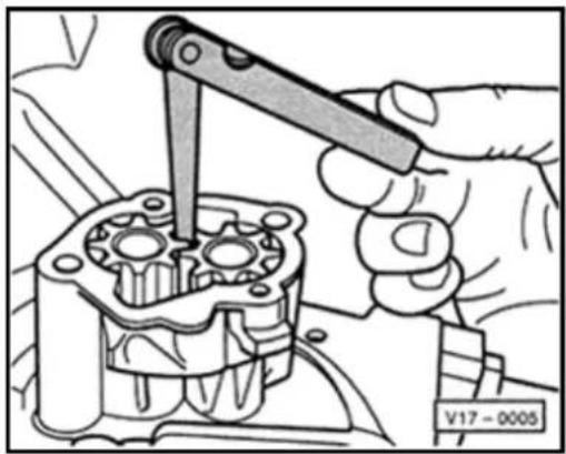
natural_image
Mechanical assembly diagram showing a hand using a tool to adjust a mechanical component (no text or symbols visible)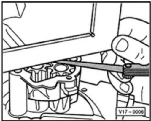
natural_image
Mechanical assembly diagram showing a hand using a tool to adjust internal components (no text or symbols visible)
Fig. 1 Checking oil pump backlash
Special tools and equipment
◆ Feeler gauge
Wear limit: 0.20 mm

Fig. 2 Checking oil pump axial clearance
Special tools and equipment
Straight edge
◆ Feeler gauge
Wear limit: 0.10 mm
17-15
Oil pan, removing and installing
Special tools and equipment
♦ VAG 1331 Torque wrench (5...50 Nm)
◆ D 176 404 A2 Silicone sealing compound
◆ Hand drill with plastic brush attachment
Flat scraper
◆ Protective goggles
Removing
- Remove center, left and right insulation trays:
⇒ Repair Manual, Body Exterior, Repair Group 50
- Unscrew bracket for Secondary Air Injection (AIR) pump motor -V101- from oil pan and from cylinder block Page 26-26, item - 17 -.
- Drain engine oil.
Note:
Observe waste disposal regulations!
- Remove oil pan.
17-16
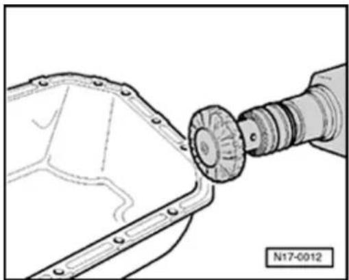
natural_image
Technical illustration of a mechanical assembly with a cylindrical component inserted into a housing (no text or symbols)- If necessary loosen oil pan with light blow rubber mallet.
- Remove sealant residue from cylinder block a flat scraper.
- Remove sealant residue from pan with a brush, e.g. a hand drill with a plastic brus attachment (wear protective goggles).
- Clean sealing surfaces. They must be fre and grease.
Installing
Note:
Note the expiration date of the sealing compound.
Oil pan must be installed within 5 minute applying silicone sealing compound.
17-17
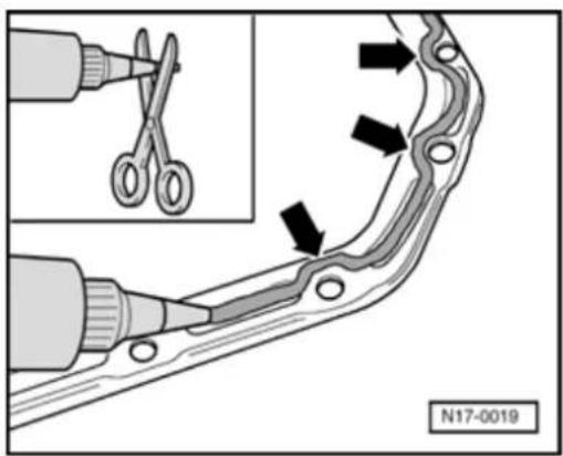

- Cut off tube nozzle at front marking (nozzle approx. 3 mm diameter).
- Apply silicone sealing compound, as shown, to clean oil pan sealing surface. Sealing compound bead must be:
◆ 2...3 mm thick,
◆ and run on inside of bolt holes (arrows).
Note:
The sealing compound bead must not be thicker, otherwise excess sealing compound will enter the oil pan and may block the oil suction pipe strainer.
17-18
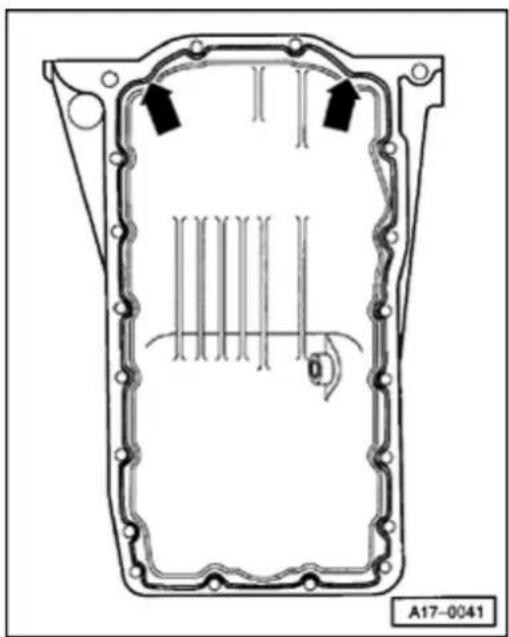
natural_image
Technical line drawing of a mechanical component with internal channels and mounting holes (no text or symbols)
- Apply silicone sealing compound bead as illustrated to clean sealing surface of oil pan.
- Install oil pan immediately and tighten all pan bolts lightly.
- Tighten oil pan bolts to 12 Nm.
- Tighten bolts for pan/transmission to 45 Nm.
- Tighten bracket for secondary air pump motor:
Securing bolts to oil pan: 8 Nm
Securing bolts to cylinder block: 20 Nm
Note:
The sealing compound must be allowed to cure for approx. 30 minutes after installing the oil pan. After this time the engine may be filled with engine oil.
The rest of the assembly is basically in reverse order to the disassembling sequence.
17-19
Oil pressure and oil pressure switch, checking
Special tools and equipment
♦ VAG 1342 Oil pressure tester
◆ VAG 1342/14 Adapter
◆ VAG 1527 B Diode test lamp
◆ VAG 1594 A Adapter set
17-20
Test conditions
- Engine oil level OK, checking Page 17-8, Fig. 2.
- Engine oil temperature at least 80 °C (coolant fan must have run once).
- Selector lever must be in position "P" or "N" on vehicles with an automatic transmission.
Note:
Functional check and servicing the optical and acoustic oil pressure warning:
⇒ Electrical Wiring Diagrams, Troubleshooting & Component Locations
Checking oil pressure switch
- Remove center, left and right insulation trays:
⇒ Repair Manual, Body Exterior, Repair Group 50 - Remove front bumper:
⇒ Repair Manual, Body Exterior, Repair Group 63 - Bring lock carrier into service position:
⇒ Repair Manual, Body Exterior, Repair Group 50
17-21
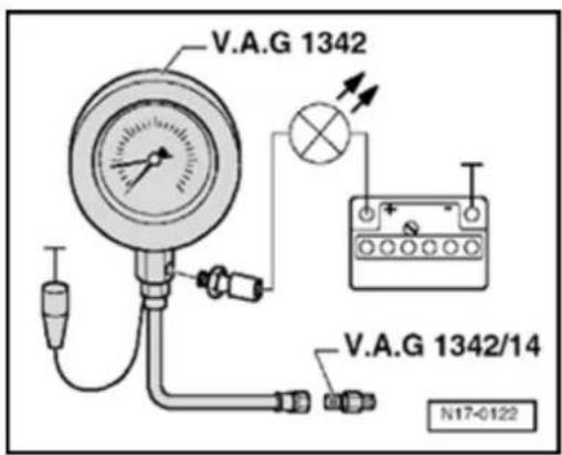

- Remove Oil pressure switch -F1- and screw into tester.
- Screw tester VAG 1342 with adapter VAG 1342/14 into oil filter bracket instead of oil pressure switch.
Note:
Observe installation position of adapter: The tapered connecting socket of the adapter is screwed to the pressure hose of the tester.
- Connect brown wire of tester to Ground (-).
- Connect diode test lamp VAG 1527 B to battery positive (+) and oil pressure switch using adapter cables from VAG 1594 A.
LED must not light up.
If the LED lights up:
- Replace Oil pressure switch -F1- Page 17-9, item -2-.
If the LED does not light up:
- Start engine and run at idling speed. At 1.2...1.6 bar LED must light up; otherwise replace Oil pressure switch -F1- Page 17-9, item - 2 -.
17-22
Checking oil pressure
- Check oil pressure at different revolutions:
2,000 rpm: 3.0...5.5 bar
above 2,000 rpm: maximum 7.0 bar.
If the specifications are not attained:
- Repair mechanical damage, e.g. bearing damage.
At higher engine speeds oil pressure must not exceed 7.0 bar.
If the specification is exceeded:
- Check oil galleries.
- Replace oil pump if necessary Page 17-12, Disassembling and assembling oil pump.
Cooling system component servicing
CAUTION!
When performing repair work, especially to the confined conditions in the engine compartment, pay attention to the follow
Route all types of lines (e.g. for fuel, hydraulics, EVAP system, coolant, refrigerant, brake fluid and vacuum) as as electrical wiring so that the original positions are restored.
Make sure sufficient clearance to all m or hot components.
Note:
When the engine is warm the cooling sy under pressure. If necessary release pre before commencing repair work.
◆ Hoses are secured with spring-type clips cases of repair only use spring-type clip.
Assembly tool VAS 5024 or hose clip pli VAG 1921 are recommended for installing spring-type clips.
When installing coolant hoses route stress so that they do not come into contact with components (observe markings on cool connection and hose).
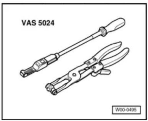
natural_image
Technical line drawing of two VAS 5024 tool holders with handle and clamp (no text or symbols on the tools themselves)
19-2
Perform cooling system leakage test with cooling system tester VAG 1274 and adapters VAG 1274/8 and VAG 1274/9.
Parts of cooling system, body side Page 19-3.
Parts of cooling system, engine side Page 19-6.
Coolant hose connection diagram Page 19-11
Disassembling and assembling coolant thermostat housing Page Page 19-13.
Draining and filling coolant Page 19-15.
Coolant mixing ratios Page 19-15, Draining and filling coolant.
19-3

Components of cooling system, body side
1 - Radiator
♦ Removing and installing ⇒ Page 19-22
◆ After replacement also replace entire coolant
2 - O-ring
◆ Replace if damaged
3 - Upper coolant hose
◆ Secured to radiator with a quick release coupling ◆ Check seated securely
◆ Coolant hose connection diagram ⇒ Page 19-11
4 - 15 Nm
5 - Bracket
◆ For radiator
◆ Observe installation position
6 - Washer
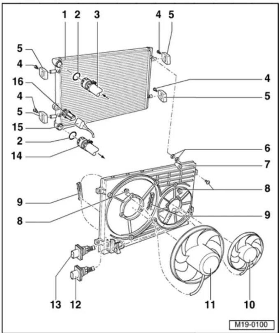
19-4
7 - Air ducting
8 - 5 Nm
9 - Retaining clip
◆ Check for secure seating
10 - Right coolant fan - V35-
◆ Checking ⇒ Page 19-31
♦ Removing and installing ⇒ Page 19-22
14 - Lower coolant hose
◆ Secured to radiator with a quick release coupling
◆ Check seated securely
◆ Coolant hose connection diagram ⇒ Page 19-11
15 - Connector
◆ For Coolant Fan Control (FC) Thermal switch - F18-
16 - Coolant Fan Control (FC) Thermal switch - F18-, 35 Nm
◆ For electric fan
♦ Switching temperatures: 1st speed - On:
92...97
° C, Off:
84...91
°C
2nd.
speed -
On:
99...105
°C, Off:
91...98
°C
19-6
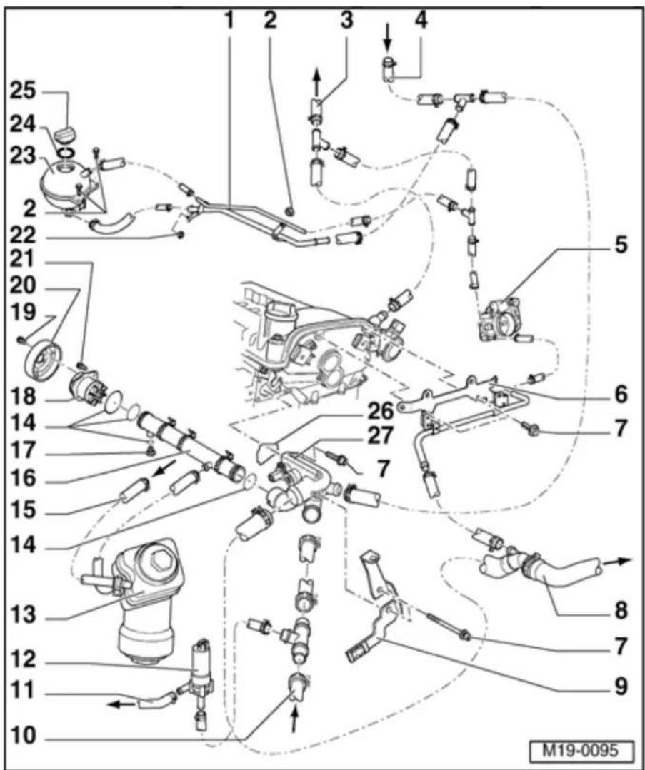
Components of cooling system, engine side
1 - Coolant pipe
◆ Secured to exhaust gas manifold together with heat shield
2 - 10 Nm
3 - To heat exchanger
◆ Coolant hose connection diagram ⇒ Page 19-11
4 - From heat exchanger
◆ Coolant hose connection diagram ⇒ Page 19-11
5 - Throttle valve control module -J338-
◆ Heated by coolant
◆ Removing and installing:
⇒ Repair Manual, 2.8 Liter VR6 4V Fuel Injection & Ignition, Engine Code(s): BDF, Repair Group 24
19-7

6 - Cable guide
◆ For coolant hoses and wiring harness
7 - 8 Nm
8 - Upper coolant hose
- To top off radiator - Check for secure seating
◆ Coolant hose connection diagram ⇒ Page 19-11
9 - Bracket
◆ For wiring harness
10 - Lower coolant hose
- From bottom of radiator - Check for secure seating
♦ Coolant hose
connection diagram ⇒ Page 19- 11
11 - To cylinder block
◆ Coolant hose connection diagram ⇒ Page 19-11
19-8

12 - After-Run Coolant pump - V51-
◆ Secured to cylinder block by a bracket
◆ Checking
⇒ Page
19-33
13 - Oil cooler
◆ Disassembling and assembling Page 17-9, Disassembling and assembling oil filter housing
14 - O-ring
♦ Replace
15 - From cylinder block
◆ Coolant hose connection diagram ⇒ Page 19-11
16 - Coolant pipe
17 - Sealing plug, 2 Nm
19-9

18 - Coolant pump
◆ Observe installation position
◆ Check for ease of movement
◆ If damaged or leaking replace complete
♦ Removing and installing ⇒ Page 19-26
19 - 20 Nm
20 - Belt pulley
◆ For coolant pump
♦ Removing and installing ribbed belt ⇒ Page 13-19
♦ Removing and installing ⇒ Page 19-26, Removing and installing coolant pump
21 - 20 Nm
◆ Use coolant pump wrench VAG 1590 to loosen and tighten ⇒ Page 19-26, Removing and installing coolant pump
22 - 25 Nm
19-10

23 - Expansion tank
◆ Perform leak test on cooling system with cooling system tester VAG 1274 and adapter VAG1274/8
◆ Test pressure: 1.4...1.6 bar
◆ Observe markings → Page 19-15, Draining and filling cooling system
24 - Seal
♦ Replace if damaged
25 - Sealing cap
◆ Check with cooling system tester VAG 1274 and adapter VAG 1274/9
Pressure relief valve must
open at a pressure of 1.4...1.6 bar
26 - Seal
◆ Replace
27 - Thermostat housing
♦ Disassembling and assembling Page 19-13
19-11

Coolant hose connection diagram
1 Transmission - oil cooler
◆ Only models with an automatic transmission
2 - Thermostat housing
3 - Cable guide
◆ For coolant hoses and wiring harness
4 - Upper coolant hose
5 - Lower coolant hose
6 - Radiator
7 - After-Run Coolant pump - V51-
8 - Oil cooler
9 - Cylinder block
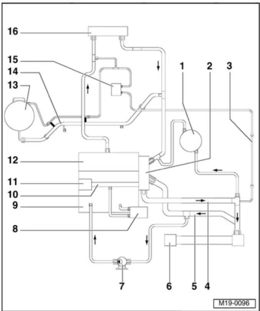
19-12
10 - Coolant pipe
◆ Between coolant pump and thermostat housing
11 - Coolant pump
12 - Cylinder head
13 Expansion - tank
14 - Coolant pipe
◆ Secured to exhaust manifold together with heat shield
15 - Throttle valve control module
16 Heat - exchanger for heating system
19-13

Coolant thermostat housing, disassembling and assembling
Note:
Routing coolant hoses to thermostat housing = Page 19-6, Parts of cooling system, engine side.
1 - O-ring
◆ Replace if damaged
2 - Retaining clip
◆ Check seated securely
3 - Thermostat housing
4 - Bracket
5 - 8 Nm
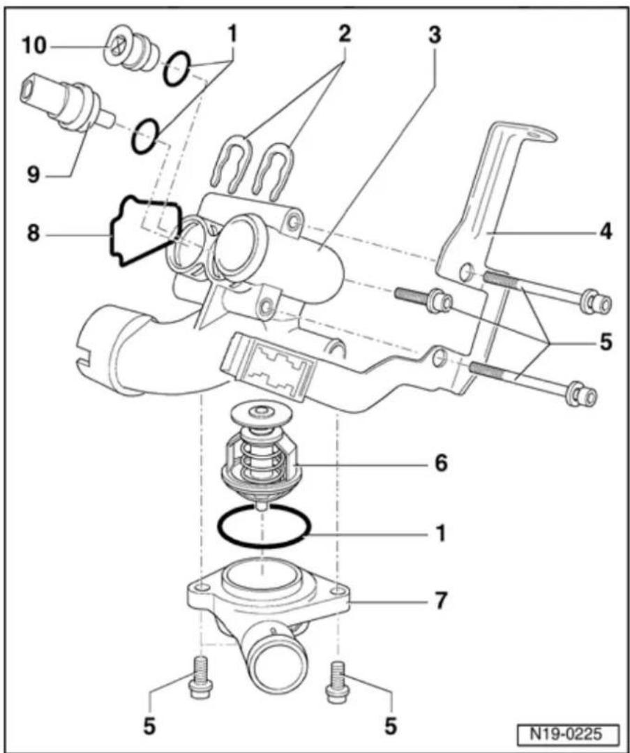
19-14
6 - Coolant thermostat
◆ Observe installation position
◆ Checking: Heat up thermostat in water
◆ Starts to open at approx. 80 °C
◆ Ends at approx. 105 °C
◆ Opening stroke at least 7 mm
7 - Unions
8 - Seal
◆ Replace
9 Engine - Coolant Temperature (ECT) sensor - G62-
◆ For engine control module
◆ With ECT sensor -G2-
◆ Release pressure in cooling system if
necessary before removing components
◆ Checking:
⇒ Repair Manual, 2.8 Liter VR6 4V Fuel Injection & Ignition, Engine Code(s): BDF, Repair Group 01
10 - Plug
◆ Release pressure in cooling system if necessary before removing components
19-15
T10007 | V.A.G 1274/8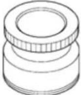 |
V.A.G 1306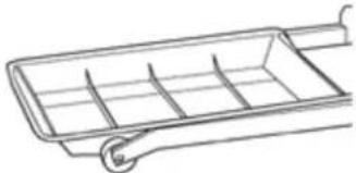 | V.A.G 1331 |
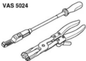 |
W19-0038
Cooling system, draining and filling
Special tools and equipment
◆ T10007
Refractometer
◆ VAG1274/8 Adapter
◆ VAG 1306
Drip tray
◆ VAG 1331 Torque wrench (5...50 Nm)
◆ VAS 5024 Assembly tool for spring-type clips
Not illustrated:
♦ VAS 6096 Coolant system charging unit
19-16
Draining
- O pen cap on coolant expansion tank.
WARNING!
Steam can be released when removing the cap from the expansion tank. Cover the cap with a cloth and open carefully.
- Remove center insulation tray:
⇒ Repair Manual, Body Exterior, Repair Group 50
- Pull out lower coolant hose retaining clip (arrow) and remove coolant hose from radiator.
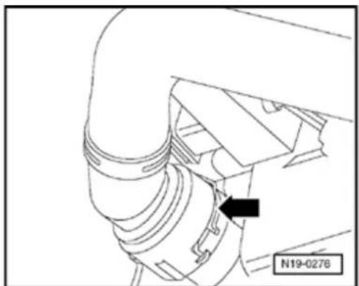
natural_image
Technical line drawing of a mechanical component with a black arrow pointing to a specific part (no text or symbols present)19-17
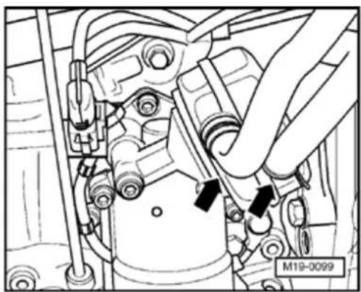
natural_image
Technical line drawing of a mechanical assembly with no visible text or symbols
- To drain coolant from engine also remove coolant hoses from oil cooler (arrows).
Note:
Observe waste disposal regulations!
Filling
Note:
Only use coolant additive G 12 in accordance with TL VW 774 D. Identification color: red
Under no circumstances must G 12 be mixed with other coolant additives!
If the fluid in expansion tank is brown, G 12 has been mixed with another coolant. In this case the coolant must be changed.
◆ G 12 and coolant additives marked "In accordance with TL VW 774 D" prevent frost and corrosion damage, scaling and also raise the boiling point of coolant. For this reason the system must be filled all year round with frost and corrosion protection additives.
Because of its high boiling point, the coolant improves engine reliability under heavy loads, particularly in countries with tropical climates.
19-18
◆ Protection against frost must be assured to approx. -25 °C (in arctic climatic countries to approx. -35 °C).
The coolant concentration must not be reduced by adding water even in warmer seasons and in warmer countries. The anti-freeze ratio must be at least 40%.
If for climatic reasons a higher frost protection is required, the amount of G 12 can be increased, but only up to 60% (frost protection to about -40°C), as otherwise frost protection is reduced again and cooling effectiveness is also reduced.
♦ Refractometer T10007 is recommended for determining the current density of the anti-freeze.
If radiator, heat exchanger, cylinder head or cylinder head gasket are replaced, do not reuse old coolant.
Recommended mixture ratios:
| Anti-freeze to | Anti-freeze proportion | G 121) | Water1)2) |
| -25 °C | 40% | 3.7 l | 5.5 l |
| -35 °C | 50% | 4.6 l | 4.6 l |
^1) The quantity of coolant can vary in accordance with the equipment fitted to the vehicle.
2) Only use clean drinking water.
19-19
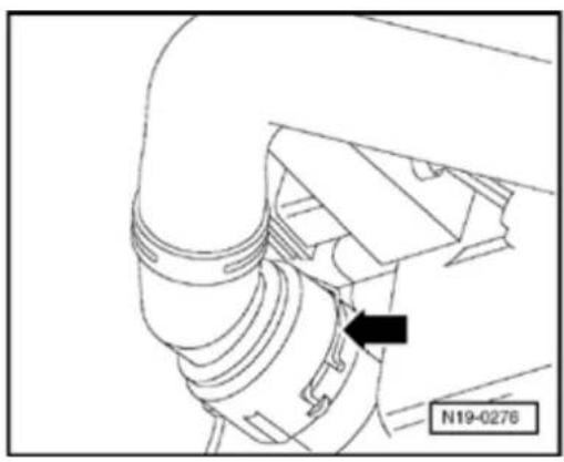
natural_image
Technical line drawing of a mechanical component with a black arrow pointing to a specific part (no text or symbols present)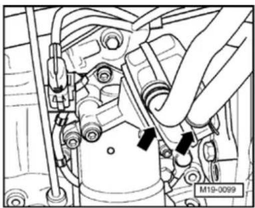
natural_image
Technical line drawing of a mechanical assembly with no visible text or symbolsWork sequence
- I install lower coolant hose and secure with retaining clamp (arrow).
- Slide coolant hoses onto oil cooler unions (arrows) and secure with spring-type clamps. - Install center insulation tray: ⇒ Repair Manual, Body Exterior, Repair Group 50
19-20
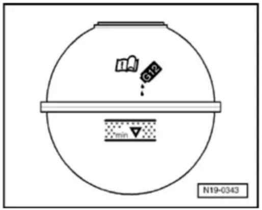
Without using coolant system charging unit VAS 6096

- F ill coolant slowly up to top mark of hatched field on expansion tank.
Using coolant system charging unit VAS 6096
- Screw adapter V.A.G1274/8 onto expansion tank.
- F ill coolant system using coolant system charging unit VAS 6096:
⇒ See instruction manual for coolant system charging unit VAS 6096
With and without coolant system charging unit VAS 6096
- Seal expansion tank.
- Switch off heater and air conditioner.
- Start engine and maintain an engine speed of about 2000 rpm for approx. 3 minutes.
- Allow engine to run at idling speed until lower hose on radiator becomes hot.
- Switch ignition off.
19-21
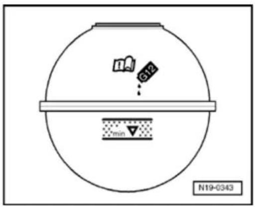

- Check coolant level and top up coolant if necessary:
At normal engine operating temperature coolant level must reach top mark of hatched field.
When engine is cold coolant level should be around middle of hatched field.
19-22
T10007 | V.A.G 1306 |
V.A.G 1331 | 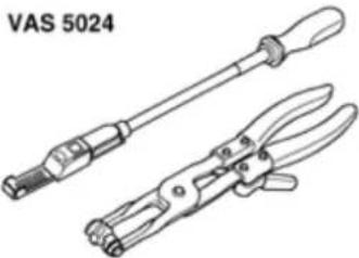 |
W19-0019
Radiator and coolant fan, removing and installing
Special tools and equipment
◆ T10007
Refractometer
♦ VAG 1306
Drip tray
◆ VAG 1331 Torque wrench (5...50 Nm)
◆ VAS 5024 Assembly tool for spring-type clips
19-23
Removing
- Remove center, left and right insulation trays:
⇒ Repair Manual, Body Exterior, Repair Group 50 - Disconnect connectors from thermal switch and coolant fan.
- Remove front bumper:
⇒ Repair Manual, Body Exterior, Repair Group 63 - Bring lock carrier into service position:
⇒ Repair Manual, Body Exterior, Repair Group 50 - Drain coolant Page 19-15.
- Pull out upper coolant hose retaining clip (arrow) and remove coolant hose from radiator quick release coupling.
Models with air conditioning:
- Observe additional information and removal work Page 19-24.
19-24
- Remove radiator securing bolts from side of radiator and take radiator with fans out downward.
Installing
Install in reverse sequence ; note the following points:
- Check electrical connections and routing:
⇒ Electrical Wiring Diagrams, Troubleshooting & Component Locations
- Fill with coolant Page 19-15.
Additional information and assembly work on models with air conditioning
CAUTION!
The air conditioning refrigerant circuit must not be opened.
Note:
To prevent damage to the condenser as well as to the refrigerant lines/hoses, ensure that lines and hoses are not stretched, kinked or bent.
- Remove retaining clamp(s) from refrigerant lines.
19-25
- Remove securing bolts from fan shroud and remove fan shroud and fan.
- Remover radiator securing bolts from side of radiator.
- Remove condenser from radiator.
- Secure condenser to body, so that refrigerant lines/hoses are not under stress.
- Swing radiator out downward.
19-26
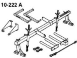 | T10007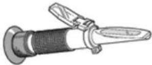 |
V.A.G 1306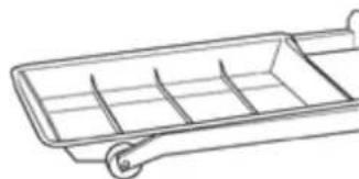 | V.A.G 1331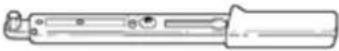 |
V.A.G 1332 | W19-0020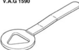 |
W19-0020
Coolant pump, removing and installing
(with engine installed)
Special tools and equipment
◆ 10-222A
Engine
support
bracket with
legs 10-
222A/1
T10007
Refractometer
VAG 1306
Drip tray
VAG 1331
Torque
wrench (5...50
Nm)
VAG 1332
Torque
wrench
(40...200 Nm)
VAG 1590
Coolant pump
wrench
19-27
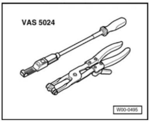
natural_image
Technical line drawing of two VAS 5024 tool holders with handles and clamps (no text or symbols on the devices themselves)
◆ VAS 5024 Assembly tool for spring-type clips
♦ VAS 5085 Ladder
Removing
- Remove engine cover.
- Remove center and right insulation trays:
⇒ Repair Manual, Body Exterior, Repair Group 50
- Remove ribbed belt Page 13-19.
- Pull off crankcase breather connecting hose between cylinder head cover and intake hose on cylinder head cover.
Note:
Press buttons on hose couplings to disconnect.
- Drain coolant Page 19-15.
19-28
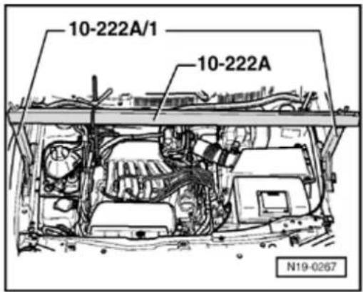
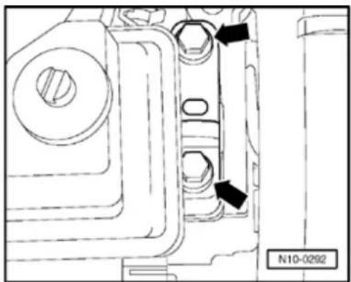
natural_image
Technical line drawing of a mechanical component with two arrows pointing to features, labeled N10-0292 (no readable text or symbols beyond label)
- Install engine support bracket 10-222A with legs 10-222A/1.
- Insert securing hook of supporting device in right lifting eye of cylinder block and put engine under slight tension.

- Unbolt engine side of assembly mounting from top of engine bracket (arrows).
Note:
Use ladder VAS 5085 to remove securing bolts.
- Lower engine on supporting device only as far as necessary to remove coolant pump.
19-29
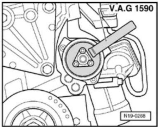
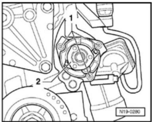
- Remove belt pulley. Counter-support belt pulley with water pump wrench VAG 1590 when doing this.
Note:
If engine has been removed, it is not necessary to remove belt pulley. The coolant pump securing bolts can be unscrewed through the holes in the pulley.
- Unscrew coolant pump securing bolts -1- and remove coolant pump -2-.
Note:
To remove the coolant pump, push the engine to one side using a lever if necessary.
19-30
Installing
Install in reverse sequence; note the following points:
- Moisten new O-ring with coolant.
- Insert coolant pump into cylinder block and tighten securing bolts to 20 Nm.
- Fit pulley and tighten securing bolts to 20 Nm.
- Align engine assembly mountings Page 10-18, Aligning engine and transmission mountings.
Note:
Torque settings for assembly mountings Page 10-21.
- Install ribbed belt Page 13-19.
- Fill with coolant Page 19-15.
19-31
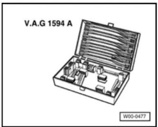
Coolant fan, checking
Special tools and equipment

◆ VAG 1594 A Adapter set
♦ Wiring diagram
Test conditions
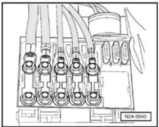
natural_image
Technical line drawing of an electrical connector with multiple terminal blocks and wiring (no text or symbols)
- Main fuses must be OK.
- Coolant Fan Control (FC) Thermal switch -F18- is OK.
19-32
Test sequence
- Remove left-hand insulation tray:
⇒ Repair Manual, Body Exterior, Repair Gr 50
- Disconnect 3-pin connector from Coolant Control (FC) Thermal switch -F18-.
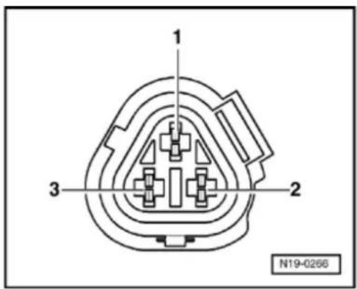

- Bridge contact -1- and contact -2- of conr using adapter cables from VAG 1594 A. 1st speed for Coolant fans -V7- and -V35 start.
- Switch ignition on.
- Bridge contact -2- and contact -3- of conr with adapter cables from VAG 1594 A. 2nd speed for Coolant fans -V7- and -V3: start.
If 1st or 2nd speeds of fans do not run:
- Locate and eliminate open circuit referring wiring diagram:
⇒ Electrical Wiring Diagrams, Troubleshoot Component Locations
If no wiring fault is detected:
- Replace Coolant fan -V7- or -V35-.
19-33
After-Run Coolant pump -V51-, checking
Special tools and equipment

◆ VAG 1527 B Diode test lamp


◆ VAG 1594 A Adapter set
♦ Wiring diagram
19-34

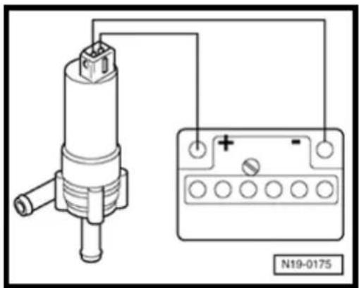
Test conditions

• All fuses must be OK.
Test sequence
- Remove center insulation tray:
⇒ Repair Manual, Body Exterior, Repair Group 50 - Disconnect 2-pin connector from After-Run Coolant pump -V51-(arrow).
Checking function

- Connect contacts of After-Run Coolant pump -V51- to battery using adapter cables from VAG 1594.
After-Run Coolant pump -V51- must start.
19-35
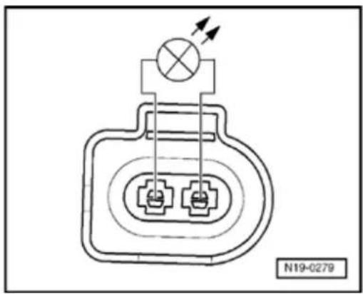
natural_image
Pure electrical circuit lines without any symbolsIf the coolant pump does not start:
- Replace After-Run Coolant pump -V51-.
If the coolant pump starts:
Checking activation
- Switch ignition off and on again.
- Connect diode test lamp VAG 1527 B to disconnected connector for After-Run Coolant pump -V51-with adapter cables from VAG 1594 A.
LED must light up.
Note:
This check must be performed within 10 minutes after switching ignition off.
If the LED does not light up:
- L ocate and eliminate open circuit referring to wiring diagram:
⇒ Electrical Wiring Diagrams, Troubleshooting & Component Locations
20-1
Components of fuel supply system, servicing
Note:
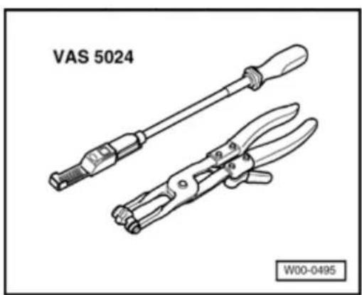
natural_image
Technical illustration of two VAS 5024 crimping tools (no text or symbols on the tools themselves)◆ Hose connections are secured with either spring-type or clamp-type clips.
◆ Always replace clamp-type clips with sp. type clips.
◆ Fuel hoses on engine must only be secu with spring-type clips. The use of clamp screw-type clips is not permitted.
◆ Assembly tool VAS 5024 or hose clip pli VAG 1921 are recommended for installing spring-type clips.
Removing and installing fuel tank with attack and fuel filter Page 20-2.
Observe safety precautions Page 20-12
Observe rules for cleanliness Page 20-
Observe crash fuel shut-off Page 20-25.
Servicing parts of the EVAP system Pag 41.
Servicing parts of Electronic Power Control Page 20-66.
20-2

Fuel tank, fuel filler and attachments, removing and installing
1 - Sealing cap
2 - Seal
♦ Replace if damaged
3 - Securing bolt
4 - Tank flap unit
◆ With rubber cup
5 - Breather line
Black
◆ Check if seated securely
◆ Clipped onto top of fuel tank
6 Ground - connection
◆ Check if seated securely
20-3
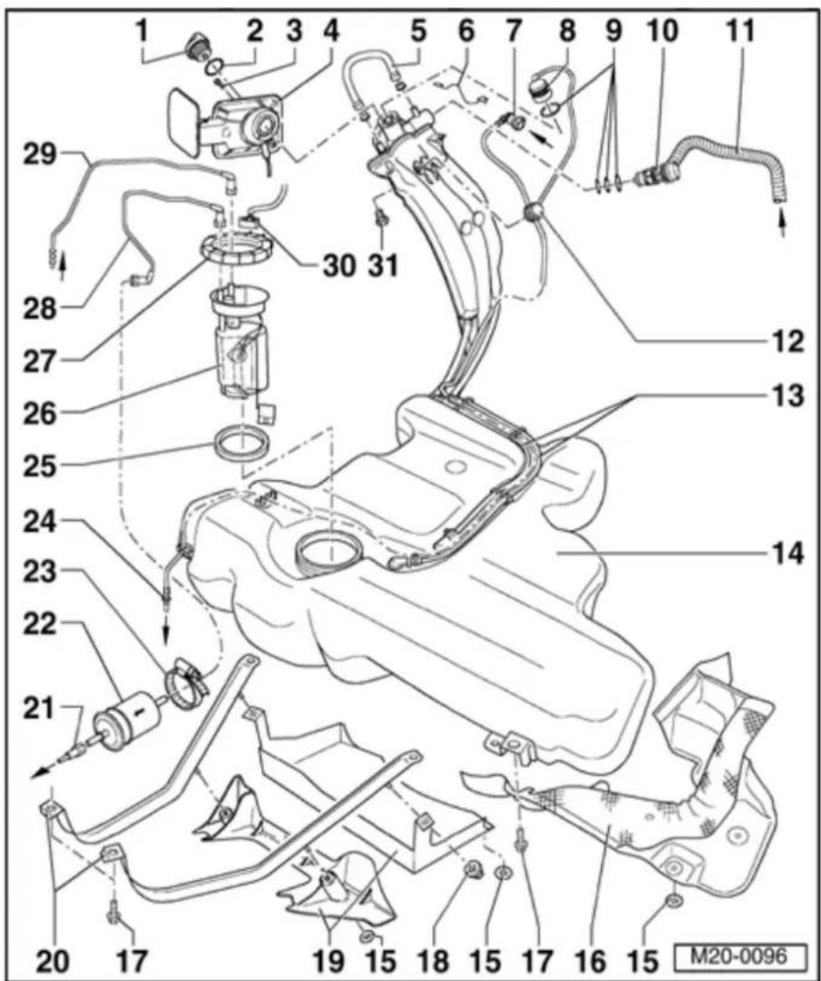
7 - Breather line
White
◆ Check for secure seating
◆ Press together at front to release
◆ From union piece
⇒
Page
20-
41,
item -
1 -
8 - Gravity valve
◆ To remove valve unclip upward out of support
◆ Check valve for through flow
Valve vertical: Open
Valve tilted 45°: Closed
9 - Seal
◆ Replace if damaged
10 - Change-over valve
◆ To remove valve unclip sideways out of socket
◆ Before installing remove sealing cap item - 1 -
◆ Checking ⇒ Fig. 2

20-4
11 - Breather line
Black
◆ Check for secure sea
◆ From union piece ⇒ Pa 20-42, iten
12 - Pressure retention val
◆ Checking = Fig. 3
13 - Breather line
Black
◆ Check for secure sea
14 - Fuel tank
When removing support with engine/transmis jack VAG 1383,
◆ Removing installing = Page 20-20
15 - Clamping washer
16 - Heat shield
◆ For fuel tan
20-5

17 - 25 Nm
18 Clamping - nut, 2 Nm
19 - Fuel tank cover
20 Securing - strap
◆ Note differing lengths
◆ Installation position: Fixing point (holes) point in direction of travel (forward)
21 - Supply line
Black
◆ Check for secure seating
◆ To pull off of fuel filter press release buttons on connecting piece
◆ To fuel supply pipe on fuel rail:
Liter VR6 4V Fuel Injection & Ignition, Engine Code (s): BDF, Repair Group 24

22 - Fuel filter
◆ Installation position: Arrow points in direction of flow
23 - Screw-type clip
◆ Observe installation position ⇒ Fig. 4
24 - Breather line
White
◆ Check for secure seating
◆ Clipped onto side of fuel tank
◆ To EVAP canister purge regulator valve - N80-
25 - Seal
♦ Replace if damaged
When installing, insert seal dry into fuel
tank opening
◆ Moisten with fuel only when installing fuel delivery unit flange
20-7

26 - Fuel delivery unit
◆ Observe installation position of flange on fuel tank ⇒ Fig. 1
♦ Removing and installing → Page 20-15
♦ Removing and installing fuel gauge sender ⇒ Page 20-19
◆ Checking fuel pump ⇒ Page 20-26
◆ Clean strainer if soiled
27 - Union nut, 75 Nm
◆ Remove and install with key 3217
28 - Supply line
Black
◆ Check for
secure seating
◆ Clipped onto side of fuel tank
When puling off flange and fuel filter press release button on connecting piece
20-8

29 - Return line
◆ Blue or with blue marking
◆ Clipped onto side of fuel tank
◆ Check for secure seating
◆ To remove from flange press release button on connecting piece
◆ From fuel return pipe on fuel rail:
⇒ Repair Manual, 2.8 Liter VR6 4V Fuel Injection & Ignition, Engine Code (s): BDF, Repair Group 24
30 Connector
◆ Black, 4-pin
◆ For Sender
for fuel
gauge
-G-
and
Fuel
Pump
(FP) -
G6-
31 - 10 Nm
20-9
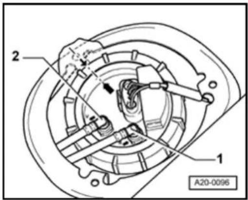
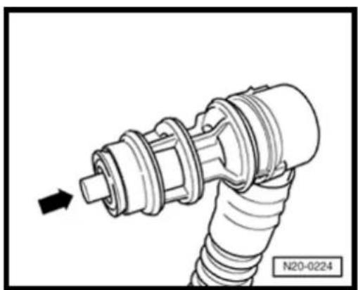
natural_image
Mechanical component diagram showing a shaft and threaded spring assembly with an arrow indicating direction (no text or symbols)
Fig. 1 Installation position of fuel delivery unit flange
Marking on sender must align with marking on fuel tank (arrows).
Blue or blue marked return line -1- to union with identification -R-.
Black supply line -2- to union with identification -V-.
Note:
After installing fuel delivery unit flange, check that the supply, return and breather lines are still clipped onto the fuel tank.

Fig. 2 Checking change-over valve
Lever in rest position: Closed
Lever pushed in direction of arrow: Open
Note:
Before installing breather valve, remove cap from fuel tank.
20-10
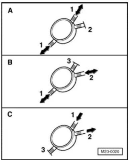

Fig. 3 Checking pressure retention valve
- Check direction of valve flow:
A) Union 1 - 1:
◆ Flow in both directions
♦ Union -2- is closed
B) Union 1 - 2:
◆ Flow in both directions
♦ Union -3- is closed
C) Union 1 - 2:
◆ Flow in only one direction
♦ Union -3- is closed
◆ Valve must close when a vacuum is applied to union -1-
20-11
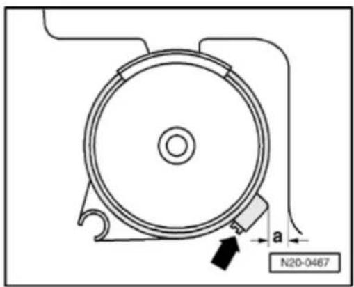

Fig. 4 Installation position of screw-type clip for fuel filter
Note:
The fuel filter is illustrated viewed from the front.
- Install screw-type clip (arrow) as shown in illustration.
Ensure sufficient clearance between clip fastener and fuel tank. Dimension "a" must be at least 5 mm.
20-12
Safety precautions when working on the fuel supply system
CAUTION!
When performing repair work, especially due to the confined conditions in the engine compartment, pay attention to the following:
Route all types of lines (e.g. for fuel, hydraulics, EVAP system, coolant, refrigerant, brake fluid and vacuum) as well as electrical wiring so that the original positions are restored.
Make sure sufficient clearance to all moving or hot components.
When removing and installing the fuel gauge sender or fuel pump (fuel delivery unit) from a full or partly full fuel tank the following must be observed:
WARNING!
Fuel supply lines are under pressure! Before removing from hose connections, wrap a cloth around the connection. Then release pressure by carefully pulling hose off connection.
20-13
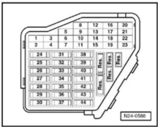
Before commencing work, switch on extractions system and place an extraction close to sender opening in the fuel tank extract escaping fuel fumes. If no exhaust extraction system is available, a radial face a displacement greater than 15m^3/h can be used (as long as motor is not in air flow)
◆ Prevent skin contact with fuel! Wear fuel resistant gloves!
For safety reasons, fuse No. 28 must be removed from fuse holder before open-in system as fuel pump can be activated by contact switch in driver's door.
20-14
Rules for cleanliness
When working on the fuel supply/injection system, pay careful attention to the following 5 rules:
- Thoroughly clean all unions and the adjacent areas before disconnecting.
◆ Place parts that have been removed on a clean surface and cover. Do not use fluffy cloths!
◆ Carefully cover opened components or seal, if the repair cannot be carried out immediately.
Only install clean components: Only unpack replacement parts immediately prior to installation. Do not use parts that have been stored loose (e.g. in tool boxes etc.).
When the system is open: Do not work with compressed air if this can be avoided. Do not move vehicle unless absolutely necessary.
20-15
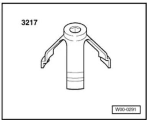
natural_image
Technical line drawing of a mechanical component with three arms and a central bore (no text or symbols)Fuel delivery unit, removing and installing
Special tools and equipment

◆ 3217 Union nut spanner


♦ VAG 1332 Torque wrench (40...200 Nm)
20-16
Removing
- Observe safety precautions before starting Page 20-12.
- Check whether a coded radio is installed. obtain anti-theft coding.
- With ignition switched off disconnect battery Ground strap.
- Fold rear seat bench forward.
- Remove cover from fuel delivery unit.
- Disconnect 4-pin connector as well as su and return lines from flange (arrows).
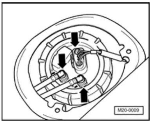
natural_image
Mechanical assembly diagram showing gear and shaft components (no text or symbols)
Note:
Press buttons on hose couplings to do so.
WARNING!
Fuel supply lines are under pressure! Be removing from hose connections wrap a around the connection. Then release pre by carefully pulling hose off connection.
20-17
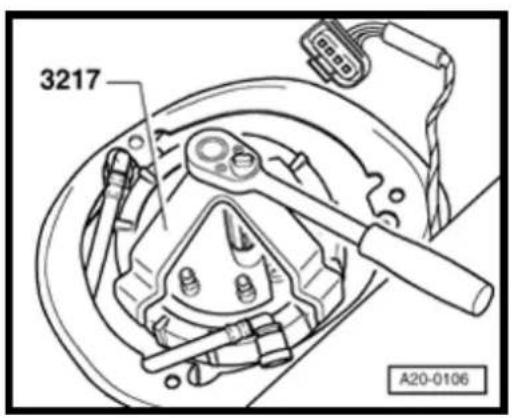
- Seal lines to avoid contamination of fuel system.

- Remove union nut with spanner 3217.
- Pull fuel delivery unit and seal out of opening in fuel tank.
Note:
If the delivery unit is to be replaced then drain old delivery unit before disposal.
Installing
- Installation of fuel delivery unit is performed in reverse order.
Note:
◆ Insert seal for fuel delivery unit flange "dry" into opening of fuel tank.
◆ Moisten inner edges of seal with fuel only when installing fuel delivery unit.
When inserting fuel delivery unit be careful to ensure that the fuel gauge sender does not become bent/deformed.
20-18


Note installation position of fuel delivery unit flange: The marking on flange must align with marking on fuel tank (arrows).
◆ Make sure tight fit of fuel hoses.
◆ After installing fuel delivery unit, check that the supply, return and breather lines are still clipped onto fuel tank.
- Check DTC memory:
⇒ Repair Manual, 2.8 Liter VR6 4V Fuel Injection & Ignition, Engine Code(s): BDF, Repair Group 01
- Adapt (match) engine control module to throttle valve control module:
⇒ Repair Manual, 2.8 Liter VR6 4V Fuel Injection & Ignition, Engine Code(s): BDF, Repair Group 24
- Perform work sequence "Procedure after interrupting voltage supply":
⇒ Repair Manual, 2.8 Liter VR6 4V Fuel Injection & Ignition, Engine Code(s): BDF, Repair Group 24
- Read readiness code:
⇒ Repair Manual, 2.8 Liter VR6 4V Fuel Injection & Ignition, Engine Code(s): BDF, Repair Group 01
- G enerate readiness code again if DTC memory has been erased or engine control module separated from permanent positive supply:
⇒ Repair Manual, 2.8 Liter VR6 4V Fuel Injection & Ignition, Engine Code(s): BDF, Repair Group 01
20-19
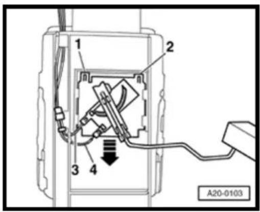
Fuel gauge sender, removing and installing
Removing
- Remove fuel delivery unit Page 20-15.
- Release connections for wires -3- and -4- and disconnect.
- Lift retaining tabs -1- and -2- with a screwdriver and pull fuel gauge sender out downward (arrows).
Installing
- Inser fuel gauge sender into guides on fuel delivery unit and push up until it engages.
- Install fuel delivery unit Page 20-15.
20-20
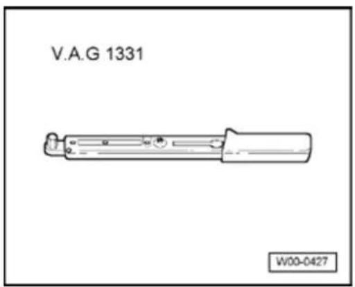
Fuel tank, removing and installing
Special tools and equipment

◆ VAG 1331 Torque wrench (5...50 Nm)
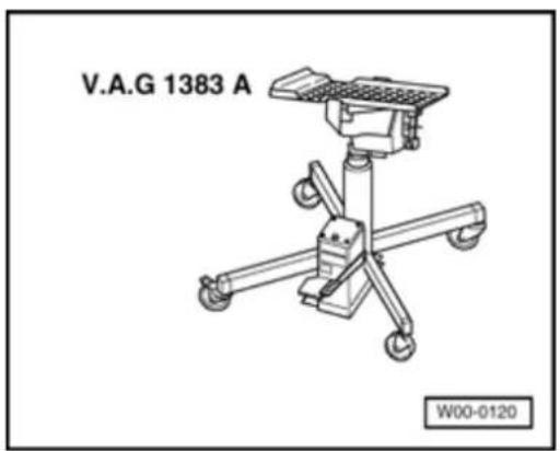
natural_image
Technical line drawing of a mechanical device with four legs and a central platform, labeled V.A.G 1383 A (no text or symbols on the diagram itself)
◆ VAG 1383 A Engine/transmission jack
20-21
Removing
- Observe safety precautions before starting work Page 20-12.
- Check whether a coded radio is installed. If so, obtain anti-theft coding.
- With ignition switched off disconnect battery Ground strap.
- Open fuel flap.
- Remove rear right wheel housing liner:
⇒ Repair Manual, Body Exterior, Repair Group 66
- Remove rear axle:
⇒ Repair Manual, Suspension, Wheels, Steering, Repair Group 42
- Drain fuel tank, clean fuel filler neck and surrounding area.
- Unscrew mounting screw and remove tank flap unit with rubber cup.
- Remove securing screws on filler neck.
- Fold rear seat bench forward.
20-22
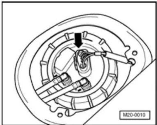
natural_image
Mechanical assembly diagram showing a motor or gear mechanism with no visible text or symbols- Remove cover from fuel delivery unit.

- Remove 4-pin connector from flange (arrow).
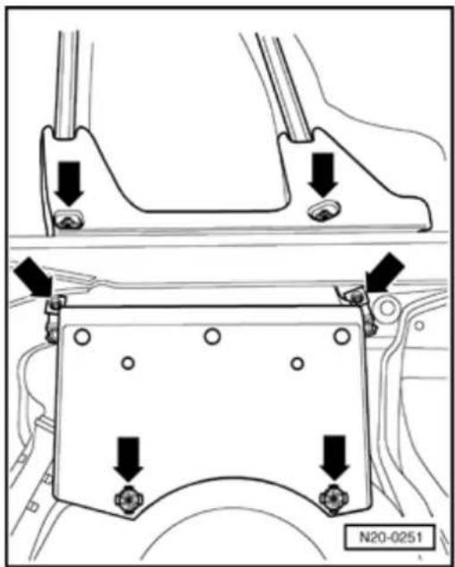

- Remove cover for fuel tank (arrows).
20-23
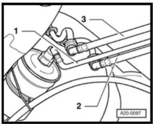

- Disconnect return line -2- (blue), supply line -1- (black) and breather line -3- (white) at connecting point.
Note:
Press buttons on hose couplings to do so.
WARNING!
Fuel supply lines are under pressure! Before removing from hose connections wrap a cloth around the connection. Then release pressure by carefully pulling hose off connection.
- Seal lines to avoid contamination of fuel system.
- Remove tensioning strap. When doing this support fuel tank with engine/transmission jack VAG 1383 A.
- Lower fuel tank.
Installing
Install in reverse sequence ; note the following points:
◆ Route breather and fuel hoses kink free.
◆ Ensure tight fit of fuel hoses.
Do not interchange supply and return hose (return hose blue or blue markings, supply hose black).
20-24
Note:
After installing fuel gauge sender, check that the supply, return and breather pipes are still clipped onto the fuel tank.
- Check DTC memory:
⇒ Repair Manual, 2.8 Liter VR6 4V Fuel Injection & Ignition, Engine Code(s): BDF, Repair Group 01 - Adapt (match) engine control module to throttle valve control module:
⇒ Repair Manual, 2.8 Liter VR6 4V Fuel Injection & Ignition, Engine Code(s): BDF, Repair Group 24 - Perform work sequence "Procedure after interrupting voltage supply":
⇒ Repair Manual, 2.8 Liter VR6 4V Fuel Injection & Ignition, Engine Code(s): BDF, Repair Group 24 - Read readiness code:
⇒ Repair Manual, 2.8 Liter VR6 4V Fuel Injection & Ignition, Engine Code(s): BDF, Repair Group 01 - Generate readiness code again if DTC memory has been erased or engine control module separated from permanent positive supply:
⇒ Repair Manual, 2.8 Liter VR6 4V Fuel Injection & Ignition, Engine Code(s): BDF, Repair Group 01
20-25
Crash fuel shut-off
Function
Models with an airbag are installed with a crash fuel shut-off system. It reduces the danger of a fire in a crash as the fuel pump is switched off via the fuel pump relay.
At the same time this system improves starting of the engine. When the door is opened the fuel pump is activated for 2 seconds to build up the pressure in the fuel system.
When opening the fuel system:
Observe safety precautions Page 20-12.
- Check activation of Fuel Pump (FP) relay -J17-with VAG 1466 A referring to wiring diagram:
⇒ Electrical Wiring Diagrams, Troubleshooting & Component Locations
20-26
3217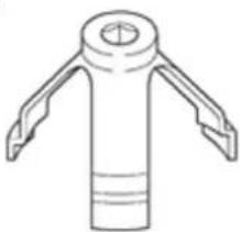 | 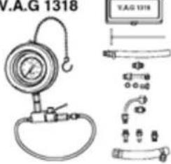 |
V.A.G 1318/11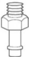 | V.A.G 1318/16 |
| V.A.G 1318/17V.A.G 1318/17-1 V.A.G 1318/17-4V.A.G 1318/17-8 V.A.G 1318/17-3 | V.A.G 1318/23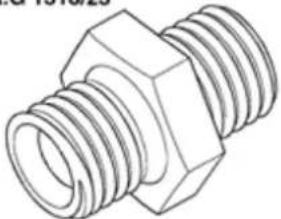 W20-0072 W20-0072 |
20-27
V.A.G 1332 | V.A.G 1348/3A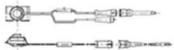 |
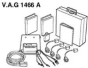 | V.A.G 1527 B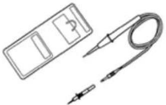 |
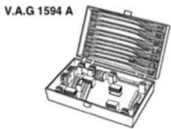 | V.A.G 1715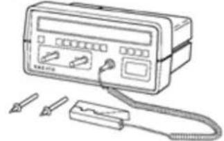 W20-0073 W20-0073 |
W20-0073
♦ VAG 1332 Torque wrench (40...200 Nm)
◆ VAG
1348/3A
Remote control with adapter cable VAG
1348/3-2
◆ VAG 1466 A Test system
◆ VAG 1527
B Diode
test lamp
◆ VAG 1594 A Adapter set
◆ VAG 1715 Multimeter
◆ Measuring container
♦ Wiring diagram
20-28

Test conditions

- Fuse 28 must be OK.
- Battery voltage must be at least 11.5 V.
- All electrical consumers, e.g. lights and rear window defroster must be switched off.
- If the vehicle is equipped with air conditioning, this must be switched off.
- Selector lever must be in position "P" or "N" on vehicles with an automatic transmission.
Note:
See functional description of crash fuel shut-off Page 20-25.
Checking function and voltage supply
- Fold rear seat bench forward.
- Remove cover from fuel delivery unit.
- Briefly operate starter.
Fuel pump must audibly run. - Switch ignition off.
20-29
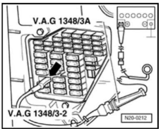
If the fuel pump does not run:
- Remove cover in front of fuse holder.

- Pull fuse No. 28 (for fuel pump) out of fuse holder.
- Connect remote control VAG 1348/3A to contact 28a to fuel pump and battery positive (+) using adapter cable VAG 1348/3-2.
- O perate remote control.
Fuel pump runs:
- Check activation of Fuel Pump (FP) relay -J17- with VA. 1466 A referring to wiring diagram:
⇒ Electrical Wiring Diagrams, Troubleshooting & Component Locations
Fuel pump does not run:

- Remove 4-pin connector from flange (arrow).

natural_image
Mechanical assembly diagram showing a motor or gear mechanism with no visible text or symbols20-30
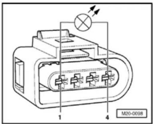
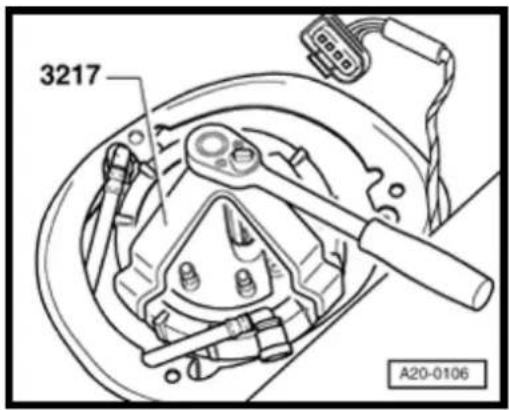

- Connect diode test lamp VAG 1527 B to outer contacts of connector using adapter cables from VAG 1594 A.
- O perate remote control. LED must light up
LED does not light-up:
- L ocate and eliminate open circuit referring to wiring diagram:
⇒ Electrical Wiring Diagrams, Troubleshooting & Component Locations
LED lights up (voltage supply OK):

- Remove union nut with spanner 3217.
- Check that electrical wires between flange and fuel pump are connected.
If no open circuit can be found:
- Fuel pump faulty, replace fuel delivery unit Page 20-15, Removing and installing fuel delivery unit.
20-31
Checking delivery rate
Test conditions
• Voltage supply OK.
- Remote control VAG 1348/3A connected.
Test sequence
- Remove filler cap from fuel tank filler neck.
- Disconnect supply hose -3- (with white marking) and collect fuel that may leak out with a cloth.
Note:
Press buttons on hose couplings to do so.
WARNING!
Fuel supply lines are under pressure! Before removing from hose connections wrap a cloth around the connection. Then release pressure by carefully pulling hose off connection.
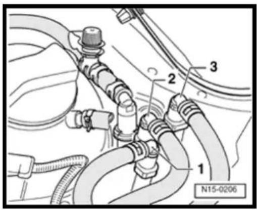
20-32


- Connect pressure gauge VAG 1318 to fuel supply pipe using adapter VAG 1318/23 and VAG 1318/17.
- Push hose adapter VAG 1318/16 onto adapter VAG 1318/11 on pressure gauge and hold hose in a measuring container.
- O pen shut-off tap on pressure gauge. Lever then points in flow direction -A-.
- Operate remote control VAG 1348/3A. Close shut-off tap slowly, until pressure gauge shows 3 bar. From now on do not alter setting of shut-off tap.
- Empty measuring container.
The quantity of fuel delivered by the fuel pump depends on the battery voltage.
- Connect multimeter to vehicle battery using adapter cables from VAG 1594 A.
- O perate remote control for 30 seconds and measure battery voltage.
20-33
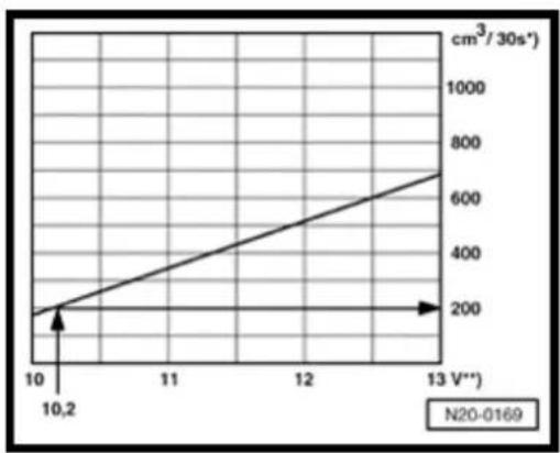
line
| Voltage (V) | Value (cm³ / 30s⁻¹) | |-------------|---------------------| | 10 | 200 | | 13 | 700 |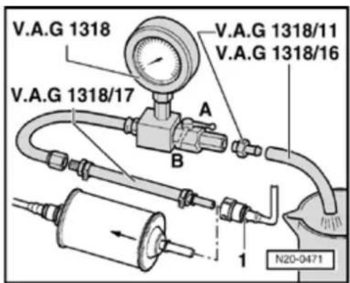

- Compare quantity of fuel delivered with nominal value.
*) Minimum delivery cm ^3 /30 seconds
**) Voltage at fuel pump with engine not running and pump running (approx. 2 volts less than battery voltage).
Example:
During the test, a voltage of 12.2 volts is measured at the battery. As the voltage at the pump is approx. 2 volts less than the battery voltage, the result is a minimum delivery of 200cm^3 /30 seconds.
If the minimum delivery rate is not attained:
- Check fuel pipes for possible restrictions (kinks) or blockages.
- Disconnect fuel line -1- from input side of fuel filter.
Note:
Press buttons on hose couplings to disconnect.
- Connect pressure gauge VAG 1318 to hose using adapter 1318/17.
- Repeat delivery rate test.
20-34
If the minimum delivery rate is now attained:
- Replace fuel filter.
If the minimum delivery rate is again not attained:
- Remove fuel delivery unit and check strainer filter for soiling.
Only if no faults have been detected up to now:
- Fuel pump faulty, replace fuel delivery unit Page 20-15, Removing and installing fuel delivery unit.
If the delivery rate has been attained but a fuel supply system fault is still suspected (e.g. intermittent failure of fuel supply system):
- Check current draw of fuel pump as follows:
- Reconnect all disconnected fuel lines.
20-35
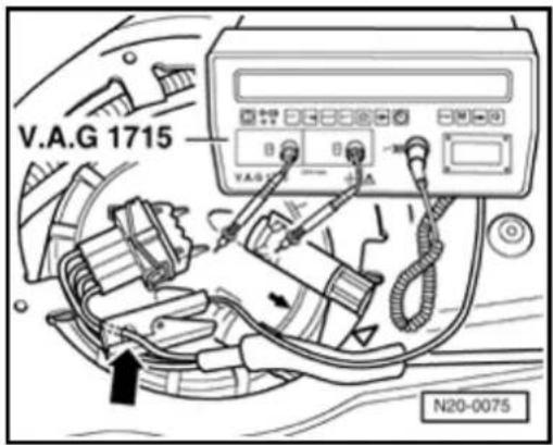

- Connect multimeter VAG 1715 to wire (arrow) for contact 1 of 4-pin connector using current pick-up clamp.
- Start engine and run at idling speed.
- Measure current draw of fuel pump.
Specification: max. 8 amps.
Note:
If the fuel system malfunction is intermittent, perform the check during a test drive with the assistance of a 2nd person.
If the current draw is exceeded:
- Fuel pump faulty, replace fuel delivery unit Page 20-15, Removing and installing fuel delivery unit.
Checking fuel pump non-return valve
Test conditions
- Remote control VAG 1348/3A is still connected.
- Pressure gauge VAG 1318 is still connected.
20-36
Test sequence
Note:
With this check the fuel supply line connections from the fuel delivery unit to the point at which the pressure gauge VAG 1318 is connected will be checked for leaks at the same time.
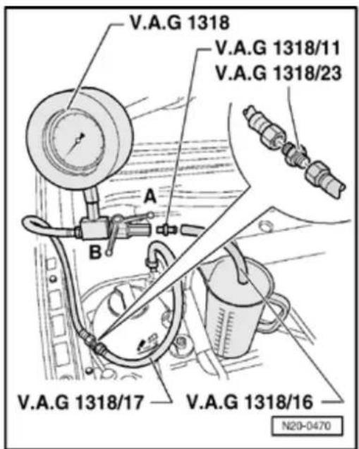

- Close pressure gauge shut-off tap (lever across flow direction - position B-).
- O perate remote control at short intervals, until a pressure of approx. 3 bar has built up.
- If pressure builds up too high, lower excess pressure by carefully opening shut-off tap.
WARNING!
Danger of spray when opening the shut-off-tap; hold container in front of the free connection on the pressure gauge.
- O bserve pressure drop on gauge. Over a duration of 10 minutes pressure must not drop below a 2.5 bar decrease.
If the pressure drops further:
20-37
- Check pipe connections for leaks.
If no wiring fault is detected:
- Fuel pump faulty, replace fuel delivery unit Page 20-15, Removing and installing fuel delivery unit.
Evaporative Emissions (EVAP) system
Function
Depending on air pressure and ambient temperature, fuel vapor will form above the level of fuel in the tank.
The EVAP system prevents these HC emissions from escaping into the atmosphere.
In limited quantities, fuel vapors located at the highest point in the tank pass through a gravity valve (which closes at an angle of 45°) and through a pressure retention valve into the EVAP canister.
The activated charcoal in the canister stores these vapors like a sponge.
When the Oxygen sensor control is active when driving (engine warm), the EVAP canister purge regulator valve -N80-(sometimes called regeneration valve), is activated (pulsed) from the engine control module depending upon load and engine speed. The opening period is dependent on the input signals.
Intake manifold vacuum draws fresh air through the vent opening on the underside of the EVAP canister during the purging procedure (regenerating the activated charcoal). The fuel vapors stored in the activated charcoal and fresh air are fed for combustion in dosed quantities.
20-39
The pressure retention valve prevents fuel vapors from being drawn from the tank when the solenoid valve is open and an intake manifold vacuum is present. It therefore ensures that the evacuation of the EVAP canister has priority.
When no voltage is applied (e.g. wiring open circuit), the solenoid valve is closed. The EVAP canister will not purge.
The vacuum pipe from the throttle valve control module to the EVAP canister has an additional by-pass which is connected with the crankcase breather valve. The non-return valve integrated in the crankcase breather valve prevents intake air entering into the crankcase during some partial load ranges. This improves the overall crankcase breathing. The by-pass guarantees the crankcase breathing.
Functional description of leak diagnosis
The EVAP system (including the fuel tank) is equipped with a leak diagnosis system. The leak diagnosis system detects leaks in the breather system.
The diagnosis is based on the pressure principle and should detect leaks with a circumference larger than 1 mm.
20-40
During the diagnosis the Leak Detection P (LDP) -144- creates a pressure of 30 mbar i EVAP system. When the pressure is attained pump switches off. If the pressure drops be predetermined value the pump switches on again. The self-diagnosis monitors the switch periods and sets a code in the Diagnostic Trouble Code (DTC) memory when the peri too short.
Observe safety precautions Page 20-12
Observe rules for cleanliness Page 20-1.
Servicing parts of the EVAP system Pag 41.
Assembly overview of EVAP system Paq 44.
Note:
◆ Hose connections are secured with either spring-type or clamp-type clips.
◆ Always replace clamp-type clips with sp. type clips.
Assembly tool VAS 5024 or hose clip pli VAG 1921 are recommended for install spring-type clips.
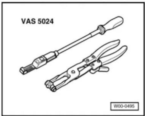
natural_image
Technical line drawing of two VAS 5024 crimping tools (no text or symbols on the tools themselves)
20-41

Components of the EVAP system, servicing
Note:
◆ Checking EVAP system for leaks ⇒ Page 20-47.
◆ Components marked with an * are checked by On Board Diagnostic (OBD):
⇒ Repair Manual, 2.8 Liter VR6 4V Fuel Injection & Ignition, Engine Code(s): BDF, Repair Group 01
◆ Components marked with ** are checked by output Diagnostic Test Mode (DTM):
⇒ Repair Manual, 2.8 Liter VR6 4V Fuel Injection & Ignition, Engine Code(s): BDF, Repair Group 01
1 - Breather line
White
◆ Check seated securely
◆ Press together at front to release
◆ To pressure retention valve ⇒ Page 20-3, item - 7
2 - Seal
◆ Replace if damaged
20-42

3 - Breather line
Black
◆ Check seated securely
◆ To change-over valve ⇒ Page 20-4, item - 11 -
4 - Junction piece
^5 Connector
◆ Black, 3-pin
6 -Vacuum line
◆ To intake manifold → Page 20-44, item - 4
7 - Leak Detection Pump (LDP) - V144-\*/\*\*
◆ In rear right wheel housing, behind wheel housing liner
Valve
will be activated by engine control module (pulsed)
◆ Checking resistance ⇒ Page 20-60
20-43
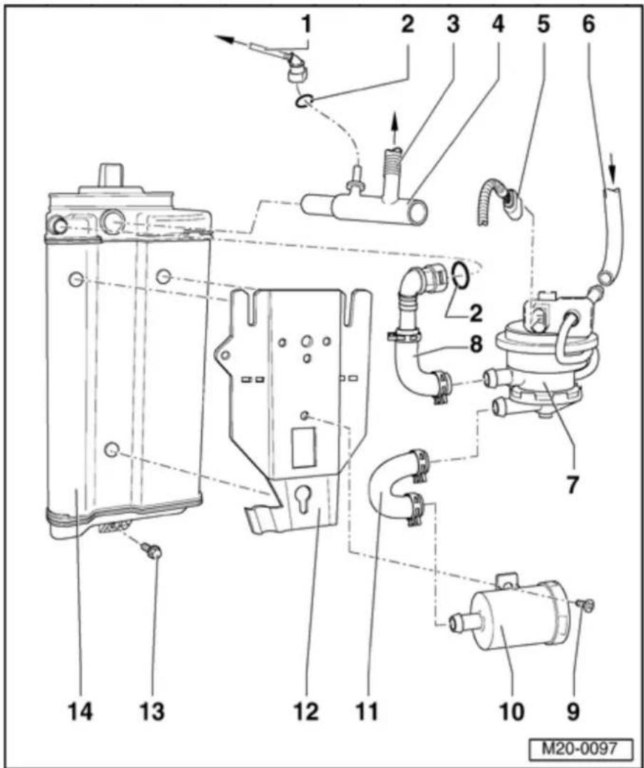
8 Connecting - hose
◆ Pressure side
9 - 3 Nm
10 - Air filter for LDP
11 Connecting - hose
◆ Suction side
12 - Bracket
13 - 10 Nm
14 - EVAP canister
◆ In rear right wheel housing, behind wheel housing liner
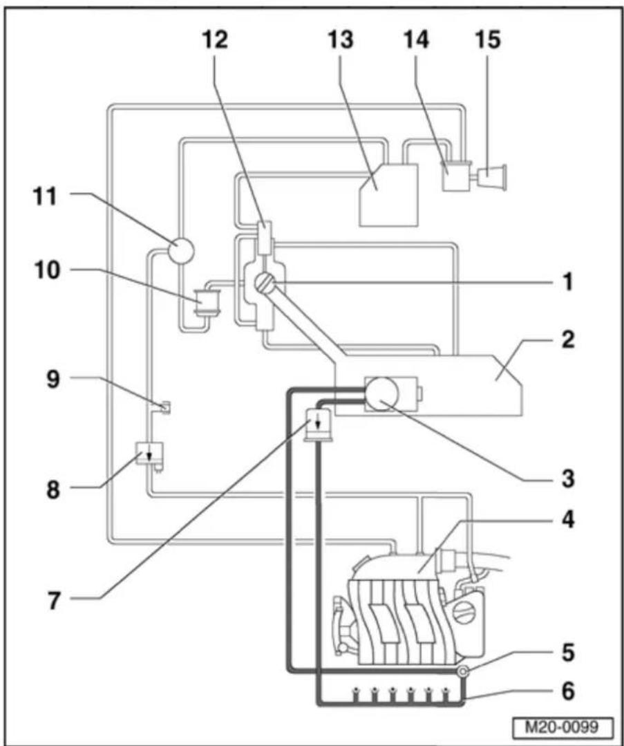
20-44
EVAP canister system, assembly overview
1 - Tank flap unit
2 - Fuel tank
3 - Fuel delivery unit
4 - Intake manifold
5 - Fuel pressure regulator
6 - Fuel rail with injectors
7 - Fuel filter
◆ Installation position: Arrow points in direction of flow

20-45
8 - EVAP canister purge regulator valve - N80-
◆ Installation position: Arrow points in direction of flow
◆ Valve will be activated by engine control module (pulsed)
◆ Checking function ⇒ Page 20-54
◆ Checking activation:
⇒ Repair Manual, 2.8 Liter VR6 4V Fuel Injection & Ignition, Engine Code (s): BDF, Repair Group 01
9 - Test union
10 - Gravity valve
11 Pressure -retention valve
12 - Change-over valve
13 - EVAP canister
◆ In rear right wheel housing, behind wheel housing liner
20-46

14 Leak
- Detection Pump (LDP) - V144-
◆ In rear right wheel housing, behind wheel housing liner
◆ Valve will be activated by engine control module (pulsed)
◆ Checking resistance ⇒ Page 20-60
◆ Checking activation:
⇒ Repair Manual, 2.8 Liter VR6 4V Fuel Injection & Ignition, Engine Code (s): BDF, Repair Group 01
15 - Air filter for LDP
20-47


EVAP system, checking for leaks
Special tools equipment, testers
◆ V.A.G 1551 Scan Tool (or vehicle system tester V.A.G 1552) with cable VAG 1551/3
Note:
All functions which could previously be performed with VAG 1551/1552 can also be performed with the new tester VAS 5051.
Test conditions
- Fuses must be OK.
- Battery voltage must be at least 11.5 V.
- All electrical consumers, e.g. lights and rear window defroster must be switched off.
- If the vehicle is equipped with air conditioning, this must be switched off.
20-48
- Selector lever must be in position "P" or "N" on models with an automatic transmission.
- Fuel pump relay -J17- must be OK, checking:
⇒ Electrical Wiring Diagrams, Troubleshooting & Component Locations - No DTCs may be stored in DTC memory:
⇒ Repair Manual, 2.8 Liter VR6 4V Fuel Injection & Ignition, Engine Code(s): BDF, Repair Group 01
Checking activation
- Check activation of LDP -V144- via output Diagnostic Test Mode (DTM):
⇒ Repair Manual, 2.8 Liter VR6 4V Fuel Injection & Ignition, Engine Code(s): BDF, Repair Group 01
If activation is OK:
- Perform functional check Page 20-49.
20-49
Functional check
Test conditions
- Throttle valve angle less than 4%,⇒d isplay group 3, display zone 3.
- Coolant temperature must be 85...110 °C →display group 4, display zone 3.
- Intake air temperature less than 80 °C, display group 4, display zone 4.
Test sequence
- Connect V.A.G 1551 Scan Tool (or V.A.G 1552). Start engine and select "Address word" 01 of engine control module.
⇒ Repair Manual, 2.8 Liter VR6 4V Fuel Injection & Ignition, Engine Code(s): BDF, Repair Group 01
Rapid data transfer Select function XX
HELP

Indicated on display
- Press keys 0 and 4 for function "Initiate basic setting" and confirm entry with Q key.
Basic setting

Indicated on display
Input display group number XXX
20-50
- Press keys 0, 7 and 1 for "Display group number 71" and confirm entry with Q key.
Note:
The engine must not be loaded during this diagnosis, if this occurs the diagnosis will be interrupted and will not start again until the engine is revved-up.
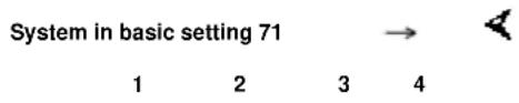
Indicated on display (1...4 = display zones)
If "Reed op." appears in display zone 1:
- Open fuel tank filler cap briefly to release pressure in fuel tank. This will close reed contact.
If the diagnosis is initiated by the engine control module the display in display zone 4 jumps from "Test OFF" to "Test ON".
Note:
If the display in display zone 4 jumps from "Test ON" to "Test OFF" during the diagnosis, repeat the diagnosis. When repeating the diagnosis test, the diagnosis can take up to 60 seconds before the display in display zone 4 jumps from "Test OFF" to "Test ON".
20-51
- Leave engine running at idling speed until display zone 4 displays specification "Syst. OK.".
If "Sys. OK." appears in display zone 4:
- Press → key.
- Press keys 0 and 6 for function "End output" and confirm entry with Q key.
- Switch ignition off.
If "Sm leak or La leak" appears in display zone 2 and "Sys. n.OK." appears in display zone 4:
- Press → key.
- Check DTC memory:
⇒ Repair Manual, 2.8 Liter VR6 4V Fuel Injection & Ignition, Engine Code(s): BDF, Repair Group 01
- Read readiness code:
⇒ Repair Manual, 2.8 Liter VR6 4V Fuel Injection & Ignition, Engine Code(s): BDF, Repair Group 01
20-52
- Generate readiness code again if DTC memory has been erased or engine control module separated from permanent positive supply:
⇒ Repair Manual, 2.8 Liter VR6 4V Fuel Injection & Ignition, Engine Code(s): BDF, Repair Group 01
If no DTC is stored in DTC memory:
- Press keys 0 and 6 for function "End output" and confirm entry with Q key.
- Switch ignition off.
- Check that fuel tank cap is completely closed or if seal is leaking, replace as necessary.
- Repeat functional check.
If fault is still present:
- Check that fuel delivery unit union nut is tight or if seal is leaking replace as necessary, Page 20-15, Removing and installing fuel delivery unit.
- Repeat functional check.
If fault is still present:
20-53
- Remove rear right wheel housing liner:
⇒ Repair Manual, Body Exterior, Repair Group 66
- Check to see if pressure hose between LDP and EVAP canister is leaking Page 20-43, item -8 - and replace if necessary.
- Check lines and line connections between EVAP canister and fuel tank flap unit or tank breather valve for leaks Page 20-44, Assembly overview of EVAP system.
- Repeat functional check.
If fault is still present:
- Remove EVAP canister and check for cracks and leaks, replace if necessary Page 20-41, Servicing components of EVAP system.
- Repeat functional check.
20-54
EVAP canister purge regulator valve -N80-, checking
In a no-current situation the solenoid valve is closed.
Special tools and equipment


◆ V.A.G 1551 Scan Tool (or vehicle system tester V.A.G 1552) with cable VAG 1551/3
Note:
All functions which could previously be performed with V.A.G 1551/1552 can also be performed with the new tester VAS 5051.

Test conditions

• The fuses must be OK.
- Battery voltage must be at least 11.5 V.
- All electrical consumers, e.g. lights and rear window defroster must be switched off.
- If the vehicle is equipped with air conditioning, this must be switched off.
20-55
- Selector lever must be in position "P" or "N" on models with an automatic transmission.
- Fuel pump relay -J17- must be OK, checking:
⇒ Electrical Wiring Diagrams, Troubleshooting & Component Locations - No DTCs may be stored in DTC memory:
⇒ Repair Manual, 2.8 Liter VR6 4V Fuel Injection & Ignition, Engine Code(s): BDF, Repair Group 01
Checking activation
- Check activation of EVAP canister purge regulator valve -N80- via output Diagnostic Test Mode (DTM):
⇒ Repair Manual, 2.8 Liter VR6 4V Fuel Injection & Ignition, Engine Code(s): BDF, Repair Group 01
If activation is OK:
- Perform functional check Page 20-56.
20-56
Functional check
Test conditions
- Coolant temperature must be at least 85 °C,⇒display group 1, display zone 2.
Test sequence
- Connect V.A.G 1551 Scan Tool (or V.A.G 1552). Start engine and select "Address word" 01 of engine control module.
⇒ Repair Manual, 2.8 Liter VR6 4V Fuel Injection & Ignition, Engine Code(s): BDF, Repair Group 01
Rapid data transfer
HELP

Indicated on display
Select function XX
- Press keys 0 and 4 for function "Initiate basic setting" and confirm entry with Q key.
Basic setting

Indicated on display
Input display group number XXX
- Press keys 0, 0 and 1 for "Display group number 1" and confirm entry with Q key.
System in basic setting 1


Indicated on display (1...4 = display zones)
1 2 3 4
20-57
Only continue with the test when
- The coolant temperature is above 85 °C -Display zone 2-
- Change to display group 70 as follows:
- Press C key.
Basic setting
Input display group number XXX
System in basic setting 70
1 2 3 4
Indicated on display
- Press keys 0, 7 and 0 for "Display group number 70" and confirm entry with Q key.
Note:
The engine must not be loaded during this diagnosis, if this occurs the diagnosis will be interrupted and will not start again until the engine is revved-up.
< Indicated on display (1...4 = display zones)
If the diagnosis is initiated by the engine control module the display in display zone 4 jumps from "Test OFF" to "Test ON".
Note:
This process can take approx. 30 seconds.
20-58
- Leave engine running at idling speed until display zone 4 displays specification TBV OK.
Note:
TBV stands for tank breather valve (EVAP canister purge regulator valve -N80-).
If "TBV OK" appears in display zone 4:
- Press → key.
- Press keys 0 and 6 for function "End output" and confirm entry with Q key.
- Switch ignition off.
If "TBV n. OK" appears in display zone 4:
- Press → key.
- Check DTC memory:
⇒ Repair Manual, 2.8 Liter VR6 4V Fuel Injection & Ignition, Engine Code(s): BDF, Repair Group 01
- Read readiness code:
⇒ Repair Manual, 2.8 Liter VR6 4V Fuel Injection & Ignition, Engine Code(s): BDF, Repair Group 01
20-59
- Generate readiness code again if DTC memory has been erased or engine control module separated from permanent positive supply.
⇒ Repair Manual, 2.8 Liter VR6 4V Fuel Injection & Ignition, Engine Code(s): BDF, Repair Group 01
If no DTC is stored in DTC memory:
- Press keys 0 and 6 for function "End output" and confirm entry with Q key.
- Switch ignition off.
- Check breather lines to EVAP canister (may be kinked).
- Check EVAP system for leaks Page 20-47.
20-60
Leak Detection Pump (LDP) - V144-, checking
Special tools and equipment

◆ VAG 1526 A multimeter, Fluke 83 multimeter or equivalent


◆ VAG 1594 Adapter set
20-61
Test conditions
- No DTCs may be stored in DTC memory:
⇒ Repair Manual, 2.8 Liter VR6 4V Fuel Injection & Ignition, Engine Code(s): BDF, Repair Group 01
Checking activation
- Check activation of LDP -V144- via output Diagnostic Test Mode (DTM):
⇒ Repair Manual, 2.8 Liter VR6 4V Fuel Injection & Ignition, Engine Code(s): BDF, Repair Group 01
If activation is OK:
- Check resistance at LDP -V144- Page 20-62.
20-62
Checking resistance
- Remove rear right wheel housing liner:
⇒ Repair Manual, Body Exterior, Repair Group 66
- Disconnect 3-pin connector (arrow) for Leak Detection Pump (LDP) -V144-.
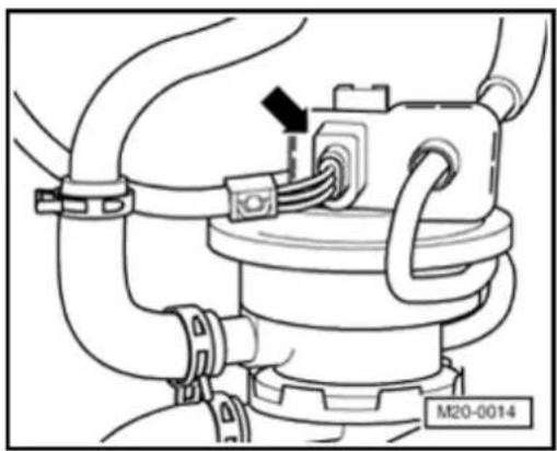
natural_image
Technical line drawing of a mechanical assembly with hoses and a valve (no text or symbols)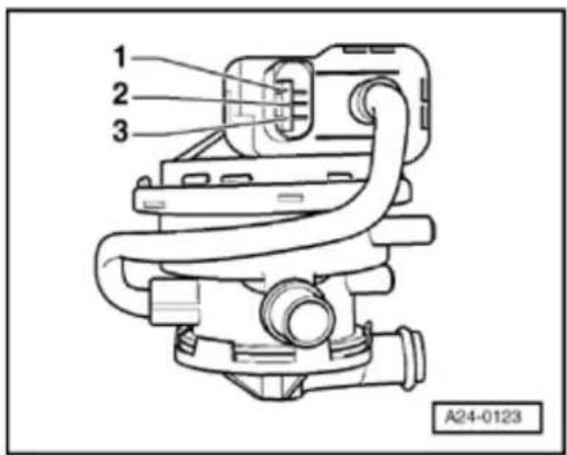
- Connect multimeter to measure resistance between contacts 1 and 3 of LDP -V144- using adapter cables from VAG 1594 A.
Specification: 640...720 Ω - Connect multimeter to measure resistance between contacts 2 and 3 of LDP -V144- using adapter cables from VAG 1594 A.
Specification: 12.5...19.5 Ω
20-63
If the specifications are not attained:
- Replace Leak Detection Pump (LDP) -V144- ⇒ Page 20-42, item -7-.
- Check DTC memory:
⇒ Repair Manual, 2.8 Liter VR6 4V Fuel Injection & Ignition, Engine Code(s): BDF, Repair Group 01
- Read readiness code:
⇒ Repair Manual, 2.8 Liter VR6 4V Fuel Injection & Ignition, Engine Code(s): BDF, Repair Group 01
- Generate readiness code again if DTC memory has been erased or engine control module separated from permanent positive supply.
⇒ Repair Manual, 2.8 Liter VR6 4V Fuel Injection & Ignition, Engine Code(s): BDF, Repair Group 01
Electronic Power Control (EPC)
Function of EPC systems
With the EPC system the throttle valve is not operated by the throttle pedal via a cable. There is no mechanical connection between accelerator and throttle valve.
The position of the accelerator is transmitted to the engine control module by two sensors (variable resistors; mounted in one housing) which are connected to the accelerator pedal.
The position of the accelerator (drivers requirement) is the main input value for the engine control module.
An electric motor (throttle actuator) in the Throttle valve control module -J338-actuates the throttle valve over the entire range of engine speeds and load.
The throttle valve is operated by the throttle actuator under instructions from the engine control module.
When the engine is not running and the ignition is switched on the engine control module moves the throttle valve exactly as prescribed by the accelerator pedal position sender. This means that when the accelerator is depressed halfway the throttle valve positioner opens the throttle valve by the same amount, the throttle is then approximately half open.
20-65
When the engine is running (under load) the engine control module can open or close the throttle valve independently of the accelerator pedal position sender.
This means that the throttle valve can already be completely open even though the accelerator pedal is depressed half way. This has the advantage of preventing throttle losses at the throttle valve.
This also gives vastly improved fuel consumption and exhaust emission levels at certain load conditions.
It is wrong to believe that EPC only consists of two components. It is a system which contains all components needed to help determine, regulate, and supervise the throttle valve position (e.g. the throttle position sensor which measures the accelerator position, the throttle valve control module, the EPC indicator lamp, the engine control module).
20-66
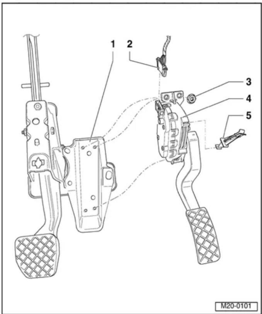
Electronic Power Control (EPC), servicing
1 - Mounting bracket
2 - Connector
◆ Black, 6-pin
◆ Gold plated contacts
3 - 10 Nm
4 - Throttle Position (TP) sensor - G79-
◆ Not adjustable
◆ TP sensor passes driver's requirements on to engine control module
◆ Remove footwell cover to remove sensor
◆ Checking ⇒ Page 20-67
◆ If replaced adapt control module for automatic transmission:
⇒ Repair
Manual, 5 Spd. Automatic Transmission 09A On Board Diagnostic (OBD); Repair Group 01
5 - Bracket
◆ For footwell cover
◆ Clipped onto accelerator pedal
20-67
V.A.G 1526 A | V.A.G 1 |
V.A.G 1598/31 | |
Throttle Position (TP) sensor -G79- / Sender -2- for accelerator pedal position - G185-, checking
Special tools and equipment
◆ VAG 1526 A multimeter, Fluke 83 multimeter or equivalent
◆ VAG 1594 A Adapter set
◆ VAG 1598/31 Test box
◆ V.A.G 1551 Scan Tool or vehicle system tester V.A.G 1552 with cable VAG 1551/3A
Note:
All functions which could previously be performed with V.A.G
1551/1552 can also be performed with the new tester VAS 5051.
♦ Wiring diagram
20-68
Note:
Only gold plated contacts may be used to service the contacts in the TP sensor / Sender for accelerator pedal position connection.
Function
Both the Throttle Position (TP) sensor -G79- and the Sender -2- for accelerator pedal position -G185- are located on the accelerator pedal and pass the driver's requirements on to the engine control module independently of one another. Both are installed together in a housing.
Test conditions
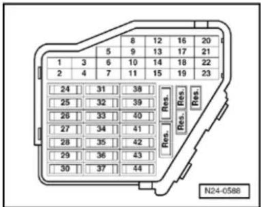

- Fuses must be OK.
- Battery voltage must be at least 11.5 V.
- All electrical consumers, e.g. lights and rear window defroster must be switched off.
- If the vehicle is equipped with air conditioning, this must be switched off.
- Selector lever must be in position "P" or "N" on models with an automatic transmission.
20-69
Test sequence
- Connect V.A.G 1551 Scan Tool (or V.A.G 1552) and select engine electronics control module with the "Address word" 01. Ignition must be switched on when doing this:
⇒ Repair Manual, 2.8 Liter VR6 4V Fuel Injection & Ignition, Engine Code(s): BDF, Repair Group 01
Rapid data transfer
HELP
Select function XX

Indicated on display
- Press keys 0 and 8 for function "Read measured value (data) block" and confirm entry with Q key.
Read measured value block

Input display group number XXX
Indicated on display
- Press keys 0, 6 and 2 for "Display group number 62" and confirm entry with Q key.
Read measured value block 62

1 2 3 4

Indicated on display: (1...4 = display zones)
- Check specifications of TP sensor -G79- at idling speed limit stop in display zone 3.
Specification: 12...17%
- Check specifications of Sender -2- for accelerator pedal position -G185- at idling speed limit stop in display zone 4
Specification: 4...10%
20-70
Note:
The engine control module calculates the angle sender voltage value as a percent of 5 Volts and displays this percentage. (5 volt supply voltage equals 100%).
- Depress accelerator pedal slowly until fully depressed and observe percentage figures in display zones 3 and 4:
Percentage display in display zone 3 must increase evenly. Tolerance range 12...97% is not fully exploited.
Percentage display in display zone 4 must increase evenly. Tolerance range 4...49% is not fully exploited.
Note:
The figure displayed in display zone 3 must always be approximately double the value displayed in display zone 4.
- Press → key.
- Press keys 0 and 6 for function "End output" and confirm entry with Q key.
- Switch ignition off.
20-71
If the displays do not indicate as described:
- Check Throttle Position (TP) sensor -G79 Sender -2- for accelerator pedal position voltage supply and wiring connections ⇒ 20-71.
Checking voltage supply and wiring to control module
- Remove cover in footwell (driver's side).
- Pull 6-pin connector from TP sensor / SeI accelerator pedal position.
- Switch ignition on.
- Connect multimeter to following connection measure voltage using adapter cables from 1594.
Contact 1 and Ground
Contact 1 and 5
Contact 2 and Ground
Contact 2 and 3
Specification: at least 4.5 V
- Switch ignition off.
If the specifications are not attained:
- Remove wiper arms and cowl panel:
⇒ Repair Manual, Electrical Equipment, Re Group 92
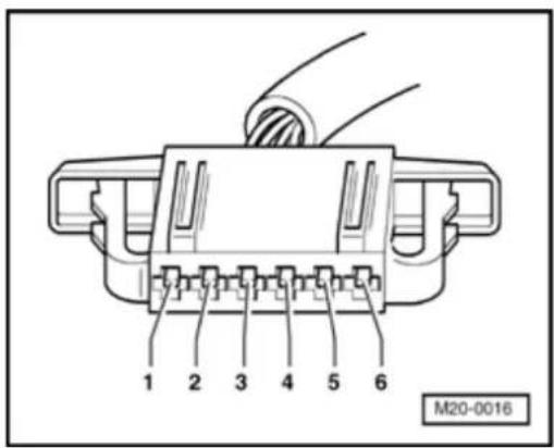
20-72

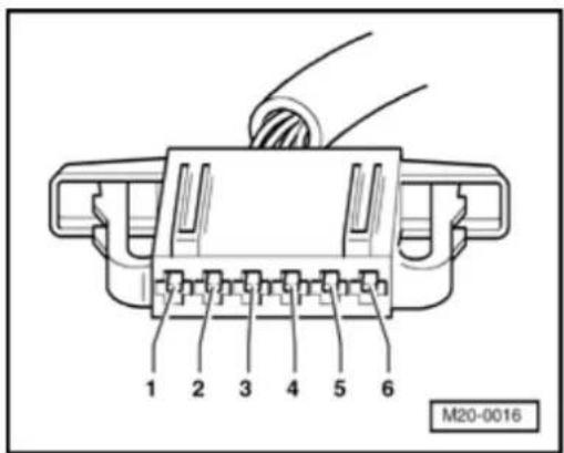
- Connect test box VAG 1598/31 to control module wiring harness. Engine control module remains disconnected.
- Check wiring for open circuit between test box and connector referring to wiring diagram. Contact 1 and socket 72 Contact 2 and socket 73 Contact 3 and socket 36 Contact 4 and socket 35 Contact 5 and socket 33 Contact 6 and socket 34
Wire resistance: max. 1.5 Ω
- Additionally check wiring for short to battery positive or Ground.
- Additionally check wires for short to one another.
20-73
If no wiring malfunction is detected:
- Replace TP sensor / Sender for accelerator pedal position Page 20-66, item - 4 -.
- Check Diagnostic Trouble Code (DTC) memory:
⇒ Repair Manual, 2.8 Liter VR6 4V Fuel Injection & Ignition, Engine Code(s): BDF, Repair Group 01 - Read readiness code:
⇒ Repair Manual, 2.8 Liter VR6 4V Fuel Injection & Ignition, Engine Code(s): BDF, Repair Group 01 - Generate readiness code again if DTC memory has been erased or engine control module disconnected from permanent positive supply:
⇒ Repair Manual, 2.8 Liter VR6 4V Fuel Injection & Ignition, Engine Code(s): BDF, Repair Group 01
Models with an automatic transmission
- Adapt (match) transmission control module:
⇒ Repair Manual, 5 Spd. Automatic Transmission 09A On Board Diagnostic (OBD); Repair Group 01; Basic setting
20-74
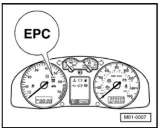
Significance of Electronic Power Control (EPC) warning lamp
Location of EPC warning lamp
When the ignition is switched on the engine control module checks all components which are important for the correct functioning of the electronic power control.
If malfunctions are detected in the electronic power control system when the engine is running the engine control module will switch on the EPC lamp. These malfunctions are identified accordingly in the Diagnostic Trouble Code (DTC) table. Simultaneously an entry is made in the engine control module DTC memory.
- Check function of EPC warning lamp:
⇒ Repair Manual, 2.8 Liter VR6 4V Fuel Injection & Ignition, Engine Code(s): BDF, Repair Group 01
Exhaust system components, servicing
Note:
After working on the exhaust system make sure that the system is not under stress, and that it has sufficient clearance to the bodywork. If necessary, loosen double clamp(s) and align muffler and exhaust pipe so that sufficient clearance is maintained to the bodywork and the support elements/mountings are evenly loaded.
◆ Replace self-locking nuts.
26-2
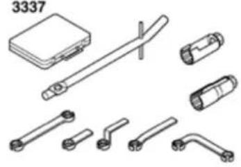 | V.A.G 1331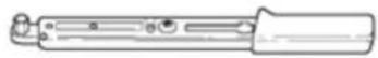 |
V.A.G 1332 | |
 |
Special tools and equipment
◆ 3337 Oxygen sensor ring spanner
♦ VAG 1331 Torque wrench (5...50 Nm)
♦ VAG 1332 Torque wrench (40...200 Nm)
26-3

Exhaust manifold, front exhaust pipe and catalytic converter with attachments
Note:
◆ Replace self-locking nuts.
◆ Components marked with an * are checked by On Board Diagnostic (OBD):
⇒ Repair Manual, 2.8 Liter VR6 4V Fuel Injection & Ignition, Engine Code(s): BDF, Repair Group 01
1 - Gasket
♦ Replace
◆ 2-part
◆ Observe installation position
2 - Exhaust manifold
◆ 2-part
3 - 25 Nm
◆ Replace
4 - 23 Nm

26-4
5 - 13 Nm
6 - 25 Nm
7 - Heat shield
8 - 10 Nm
9 - Coolant pipe
◆ Secured to exhaust gas manifold together with heat shield
◆ Coolant hose connection diagram ⇒ Page 19-11
^10 Connector
◆ Black, 6-pin
◆ Gold plated contacts
26-5

11 - Heated Oxygen Sensor (HO2S) - G39-*, 50 Nm
◆ Remove and install with oxygen sensor ring spanner 3337
◆ Grease only threads with G 052 112 A3 hot bolt paste (anti-seize compound). Grease must not get into slots on sensor body
◆ If seal is leaking cut open and replace.
◆ Checking oxygen sensor control:
⇒ Repair Manual, 2.8 Liter VR6 4V Fuel Injection & Ignition, Engine Code(s): BDF, Repair Group
24
^12 Connector
◆ Black, 4-pin
◆ Contacts 3 and 4 are gold plated
CAUTION!
Part numbers are for reference only. Always check with your Parts Dept. for the latest parts information.
26-6

13 Oxygen
- Sensor (O2S) Behind Three Way Catalytic Converter (TWC) - G130-*, 50 Nm
◆ Remove and install with oxygen sensor ring spanner 3337
◆ Grease only threads with G 052 112 A3 hot bolt paste (anti-seize compound). Grease must not get into slots on sensor body
◆ If seal is leaking cut open and replace
◆ Checking oxygen sensor control:
Liter VR6 4V Fuel Injection & Ignition, Engine Code(s): BDF, Repair Group 24
14 - Front exhaust pipe with catalytic converter
◆ Checking catalytic converter → Page 26-16
15 - To forward muffler
◆ ⇒ Page 26-8, item 1
CAUTION!
Part numbers are for reference only. Always check with your Parts Dept. for the latest parts information.
26-7
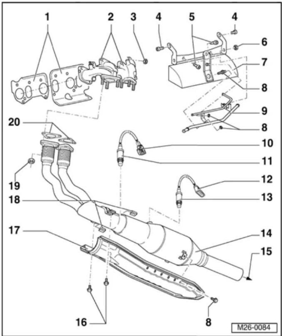
16 - 5 Nm
17 - Heat shield
◆ For catalytic converter
18 Securing - clamp
♦ Replace
◆ Slide onto retainer from rear before tightening clamp
19 - 40 Nm
♦ Replace
20 - Gasket
♦ Replace
◆ 2-part
26-8

Muffler with mountings
1 - From catalyt converter
2 - Marking
3 - Flat round head bolt
4 - Double clam
♦ Replace
♦ Observe installation position ⇒ Fig. 1
5 - M8: 25 Nm, M10: 40 Nm
6 Support - element/mounti
◆ Observe installation position ⇒ Fig. 3
26-9
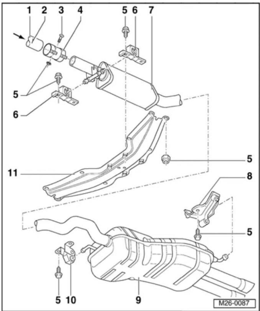
7 - Forward muffler
As standard forward muffler and rear muffler are installed as a single component In repair cases forward muffler and rear muffler are supplied individually with a double clamp for connecting together.
♦ Aligning forward muffler parallel ⇒ Fig. 2
♦ Separating points ⇒ Fi 4
♦ Aligning exhaust system ⇒ Page 26-14
8 Support
- element/mountin
9 - Rear muffler
◆
As standard forward muffler and rear muffler are installed as a single component In repair cases forward
muffler and rear muffler are supplied individually with a douk clamp for connecting together.
♦ Separating points ⇒ Fi 4
◆ Observe installation position of end pipe ⇒ Fig. 5
26-10

10 Support
- element/mouni
11 - Tunnel bridg
◆ With hole to align exhaL system
♦ Aligning exhaust system ⇒ Page 26-14
26-11
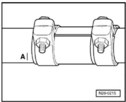
natural_image
Technical line drawing of a mechanical component with two bolts and a central shaft, labeled A and N26-0215 (no text or symbols on the diagram itself)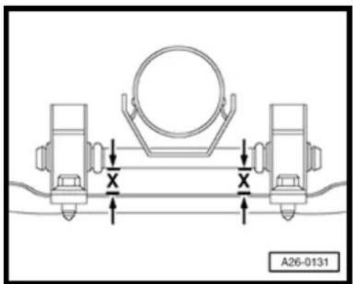

Fig. 1 Installation position of double clamp
- Position new double clamp, as illustrated, approx. 5 mm from markings -A- and tighten.
Tightening torque: 40 Nm
Note:
Mark -A- is valid for models with a manual or an automatic transmission.

Fig. 2 Aligning forward muffler parallel
Mounting pins on exhaust pipe must run parallel with tunnel bridge (dimension -x- on left and right the same).
26-12
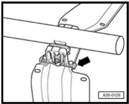
natural_image
Mechanical assembly diagram showing a lever mechanism with a black arrow indicating direction (no text or symbols present)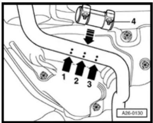

Fig. 3 Installation position of mounting
Angled side on base of mounting (arrow) points forward.

Fig. 4 Separating point on exhaust pipe
Special tools and equipment
♦ Body saw e.g. VAG 1523
- Separate exhaust pipe at right angles at separating point (arrow -2-).
- Align repair double clamp -4- in installation position on side markings (arrows -1- and -3-) as illustrated.
Tightening torque: 40 Nm
26-13
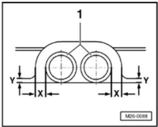

Fig. 5 Installation position of rear muffler end pipes
Work sequence
- Align rear muffler so that dimension to body -x- and -y- for end pipes -1- are equal on left and right-hand sides.
26-14
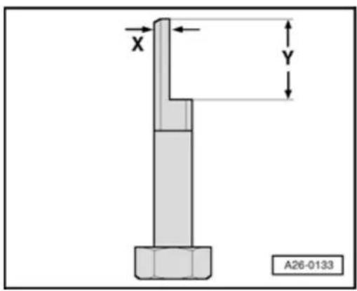
Exhaust system, aligning
Special tools and equipment
◆ M10x80 hex bolt

- L locally manufacture an alignment tool from an M10x80 hex bolt, to dimensions given.
◆ Dimension x = 4 mm
◆ Dimension Y = 25 mm
Work sequence
Note:
◆ An assistant is required to help in aligning the exhaust system.
♦ Align the exhaust system when it is cold.
◆ Pre-tension the exhaust system forward with the locally manufactured tool.
- L oosen bolts on double clamps⇒
Page 26-8, item - 4 -.
26-15
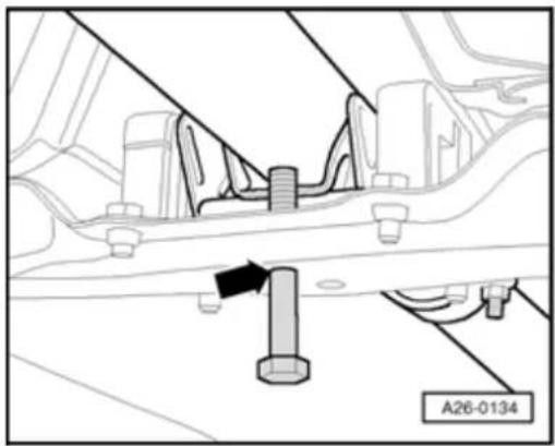
natural_image
Mechanical assembly diagram showing a bolt and connecting rod in a vehicle (no text or symbols)
natural_image
Technical line drawing of a mechanical component with two bolts and a central shaft, labeled A and N26-0215 (no text or symbols on the diagram itself)- Slide exhaust system forward until locally manufactured tool can be inserted through rearmost hole in tunnel bridge (arrow). Flattened side of locally manufactured tool faces toward exhaust system hanger pins.
- Position new double clamp, as illustrated, approx. 5 mm distance from markings -A- and tighten. Torque setting 40 Nm
Note:
Mark -A- is valid for models with either a manual or an automatic transmission.
26-16

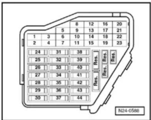
Catalytic converter, checking
Special tools and equipment

◆ V.A.G 1551 Scan Tool (or vehicle system tester V.A.G 1552) with cable VAG 1551/3
Note:
All functions which could previously be performed with V.A.G 1551/1552 can also be performed with the tester VAS 5051.
Conditions

- Fuses must be OK.
- Battery voltage must be at least 11.5 V.
- If vehicle is equipped with air conditioning, this must be switched off.
- Selector lever must be in position "P" or "N" on models with an automatic transmission.
- Exhaust system between catalytic converter and cylinder head must be free of leaks
26-17
- Coolant temperature must be at least 85 °C, d isplay group 1, display zone 2.
- Catalytic converter temperature must be at least 380^ C, =d isplay group 46, display zone 2.
- No DTCs may be stored in DTC memory:
→ Repair Manual, 2.8 Liter VR6 4V Fuel Injection & Ignition, Engine Code(s): BDF, Repair Group 01
- Oxygen sensor aging before catalytic converter is OK, checking:
⇒ Repair Manual, 2.8 Liter VR6 4V Fuel Injection & Ignition, Engine Code(s): BDF, Repair Group 24
- Oxygen sensor aging after catalytic converter is OK, checking:
⇒ Repair Manual, 2.8 Liter VR6 4V Fuel Injection & Ignition, Engine Code(s): BDF, Repair Group 24
Note:
The diagnosis will only be ended if the oxygen sensor aging diagnosis before and after catalytic converter is completed successfully first.
26-18
Test sequence
- Connect V.A.G 1551 (or V.A.G 1552). Start engine and select "Address word" 01 of engine control module.
⇒ Repair Manual, 2.8 Liter VR6 4V Fuel Injection & Ignition, Engine Code(s): BDF, Repair Group 01
Rapid data transfer
HELP

Indicated on display
Select function XX
- Press keys 0 and 4 for function "Initiate basic setting" and confirm entry with Q key.
Basic setting

Indicated on display
Input display group number XXX
- Press keys 0, 0 and 1 for "Display group number 1" and confirm entry with Q key.
System in basic setting 1


Indicated on display: (1...4 = display zones)
1 2 3 4
Only continue with the test when:
- Coolant temperature is above 85 °C -Display zone 2-
26-19
Basic setting
Input display group number XXX
| System in basic setting 46 | → | ||
| 1 | 2 | 3 | 4 |
- Change to display group 46 as follows:
- Press C key.
< Indicated on display
- Press keys 0, 4 and 6 for "Display group number 46" and confirm entry with Q key.
< Indicated on display: (1...4 = display zones)
- Depress brake pedal and hold.
- Depress accelerator down to wide open throttle position.
Engine speed will be increased by engine control module to approx. 2300 rpm.
Only continue with the test when:
- Catalytic converter temperature is above 380 °C -Display zone 2-
- Hold brake pedal and accelerator down until display in display zone 4 jumps from "Test OFF" to "Test ON".
Note:
This process can take approx. 80 seconds.
- Continue to hold brake pedal and accelerator down until display zone 4 displays specification "Cat. B1 OK.".
26-20
- Release brake and accelerator pedals.
"Cat B1 OK." appears in display zone 4:
- Press → key.
- Press keys 0 and 6 for function "End output" and confirm entry with Q key.
- Switch ignition off.
"CatB1 n.OK." appears in display zone 4:
- Press → key.
- Check DTC memory:
⇒ Repair Manual, 2.8 Liter VR6 4V Fuel Injection & Ignition, Engine Code(s): BDF, Repair Group 01
- Read readiness code:
⇒ Repair Manual, 2.8 Liter VR6 4V Fuel Injection & Ignition, Engine Code(s): BDF, Repair Group 01
26-21
- Generate readiness code again if DTC memory has been erased or engine control module disconnected from permanent positive supply:
⇒ Repair Manual, 2.8 Liter VR6 4V Fuel Injection & Ignition, Engine Code(s): BDF, Repair Group 01
If no DTC is stored in DTC memory:
- Press keys 0 and 6 for function "End output" and confirm entry with Q key.
- Switch ignition off.
- Replace front exhaust pipe with catalytic converter Page 26-6, item - 14 -.
26-22
Significance of Malfunction Indicator Lamp (MIL) for exhaust emissions
If the engine control module detects a malfunction it switches on the Malfunction Indicator Lamp (MIL).

Location MIL
Note:
The MIL can switch on in the continuous or flashing mode. Check the DTC memory in every case:
⇒ Repair Manual, 2.8 Liter VR6 4V Fuel Injection & Ignition, Engine Code(s): BDF, Repair Group 01
- Flashing mode: There is a malfunction present which can damage the catalytic converter when continuing to drive at this power output. If this occurs, continue driving only at reduced output.
Continuous mode: There is a malfunction present which causes the emissions to deteriorate. Check the Motronic engine control module and/or transmission control module.
Check the DTC memory if the customer has a complaint or if there is a driving characteristic problem and the MIL does not light up. This is because malfunctions can be stored which will not switch on the MIL immediately.
- Check function of Malfunction Indicator Lamp (MIL):
⇒ Repair Manual, 2.8 Liter VR6 4V Fuel Injection & Ignition, Engine Code(s): BDF, Repair Group 01
Secondary air system
CAUTION!
When performing repair work, especially due to the confined conditions in the engine compartment, pay attention to the following:
Route all types of lines (e.g. for fuel, hydraulics, EVAP system, coolant, refrigerant, brake fluid and vacuum) as well as electrical wiring so that the original positions are restored.
- Ensure sufficient clearance to all moving or hot components.
Function
During cold starting the secondary air system blows air in behind the exhaust valves. This produces an oxygen rich exhaust gas, causes afterburning and reduces the heating-up phase of the catalytic converter. Activation is performed by the Motronic Engine Control Module -J220- via the Secondary Air Injection (AIR) pump relay -J299- to the combi-valve.
Checking secondary air system Page 26-31.
26-24

Components of the secondary air system, removing and installing
Note:
◆ Components marked with an * are checked by On Board Diagnostic (OBD):
⇒ Repair Manual, 2.8 Liter VR6 4V Fuel Injection & Ignition, Engine Code(s) BDF, Repair Group 01
◆ Components marked with ** are checked by output Diagnostic Test Mode (DTM):
⇒ Repair Manual, 2.8 Liter VR6 4V Fuel Injection & Ignition, Engine Code(s) BDF, Repair Group 01
Secondary Air Injection (AIR) pump relay -J299-*/** Fig. 1, Position of relays in protective housing (on left in engine
compartment)
1 - Intake manifold
2 - Vacuum actuator
◆ For variable intake manifold change-over

26-25
3 - To intake manifold
4 - To fuel pressure regulator
5 - Combi-valve
◆ Checking ⇒ Page 26-41
6 - Gasket
◆ Replace
7 - Air channel
◆ In cylinder head
8 - 8 Nm
9 Ground - connection
◆ Check for secure seating
10 - Unions
◆ For combi-valve and coolant hose
◆ Coolant hose connection diagram ⇒ Page 19-11
11 - 5 Nm
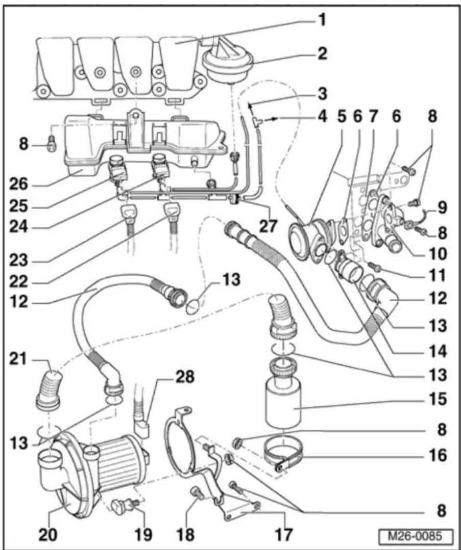
26-26
12 Pressure - hose
◆ Check seated securely
◆ Press together at front to release
13 - O-ring
◆ Replace if damaged
14 - Union
15 - Air cleaner
◆ Clean if dirty
16 Retaining - clip
17 - Bracket
◆ For secondary air pump motor
◆ Secured to oil pan and cylinder block
18 - 20 Nm
19 - Rubber bushing
26-27
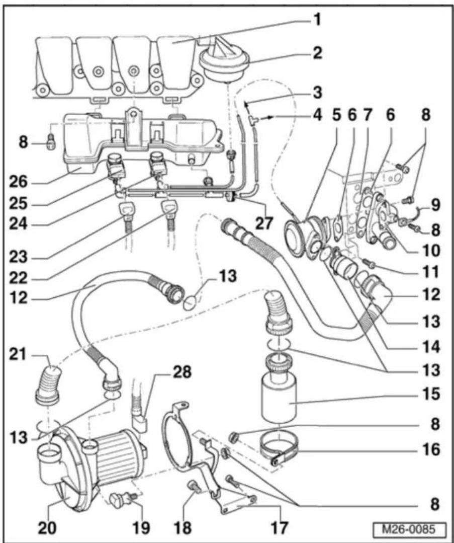
20 Secondary
- Air Injection (AIR) pump motor - V101-**
◆ Checking ⇒ Page 26-38
21 - Intake hose
◆ Check for secure seating
◆ Press together at front to release
22 Connector
◆ Black, 2-pin
◆ For intake manifold change-over valve
Mark connector and component before pulling connector off.
23 Connector
◆ Black, 2-pin
◆ For secondary air solenoid valve
Mark connector and component before pulling connector off.
24 - Intake Manifold Change- Over valve - N156- */**
◆ Valve is activated by engine control module (pulsed)
26-28

25 Secondary
- Air Injection (AIR) solenoid valve - N112- ^/*
◆ Valve is activated by engine control module (pulsed)
26 - Vacuum reservoir
27 - Non-return valve
◆ Observe installation position
- White connector faces Secondary air injection solenoid valve - N112-/Intake manifold change-over valve -N156-
28 Connector
◆ Black, 2-pin
◆ For secondary air injection pump
motor
26-29
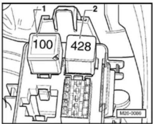

Fig. 1 Position of relays in protective housing (on left in engine compartment)
1 - Secondary Air Injection (AIR)
pump relay -J299-*/**
2 - Motronic ECM power supply relay -J271-*
Note:
If tools are necessary to pull relays or control modules out of the relay plate, first disconnect the battery Ground strap.
Before disconnecting the battery Ground strap obtain the code for radios with anti-theft coding.
26-30
Safety precautions
Observe the following if test and measuring instruments are required during a test drive:
◆ Test and measuring instruments must be secured to rear seat and operated by a 2nd person from this location.
If test and measuring instruments are operated from the front passenger's seat and the vehicle is involved in an accident, there is a possibility that the person sitting in this seat may receive serious injuries when the airbag is triggered.
26-31


Secondary air system, checking
Special tools and equipment
◆ V.A.G 1551 Scan Tool (or vehicle system tester V.A.G 1552) with cable V.A.G 1551/3
Note:
All functions which could previously be performed with V.A.G 1551/1552 can also be performed with the tester VAS 5051.
Test conditions
- Fuses must be OK.
26-32

natural_image
Technical line drawing of an electrical connector with multiple ports and wiring (no text or symbols)
- Main fuses must be OK.
- Battery voltage must be at least 11.5 V.
- All electrical consumers, e.g. lights and rear window defroster must be switched off.
- If the vehicle is equipped with air conditioning, this must be switched off.
- Fuel pump (FP) relay -J17- must be OK, checking:
⇒ Electrical Wiring Diagrams, Troubleshooting & Component Locations
- No DTCs may be stored in DTC memory:
⇒ Repair Manual, 2.8 Liter VR6 4V Fuel Injection & Ignition, Engine Code(s) BDF, Repair Group 01
Checking activation
- Check activation of Secondary air injection solenoid valve -N112- and Secondary air injection pump relay -J299- via On Board Diagnostic (OBD):
⇒ Repair Manual, 2.8 Liter VR6 4V Fuel Injection & Ignition, Engine Code(s) BDF, Repair Group 01
If activation is OK:
- Perform functional check Page 26-33.
26-33
Functional check
Test conditions
• Vacuum lines and hose connections free of leaks.
• Vacuum lines not blocked or kinked.
- Selector lever must be in position "P" or "N" on models with an automatic transmission.
- Coolant temperature must be at least 85 °C,⇒display group 1, display zone 2.
- Oxygen sensor aging before catalytic converter OK, checking:
⇒ Repair Manual, 2.8 Liter VR6 4V Fuel Injection & Ignition, Engine Code(s) BDF, Repair Group 24
Note:
The diagnosis will only be ended if the oxygen sensor aging diagnosis before catalytic converter is completed successfully first.
26-34
Test sequence
- Test drive vehicle.
Observe the valid safety precautions when road testing Page 26-30.
During the road test the following operating conditions must be fulfilled:
◆ The coolant temperature must exceed 85 °C.
When the temperature is reached, the operating conditions
Idling
Part throttle
Enrichment
Wide open throttle
Overrun
must be attained several times.
- Then:
◆ Continue running engine at idling speed.
26-35
- Connect V.A.G 1551 Scan Tool (or V.A.G 1552). Start engine and select "Address word" 01 of engine control module:
⇒ Repair Manual, 2.8 Liter VR6 4V Fuel Injection & Ignition, Engine Code(s) BDF, Repair Group 01
Rapid data transfer
HELP
Select function XX

Indicated on display:
- Press keys 0 and 4 for function "Initiate basic setting" and confirm entry with Q key.
Basic setting

Indicated on display:
Input display group number XXX
- Press keys 0, 0 and 1 for "Display group number 1" and confirm entry with Q key.
System in basic setting 1

1 2 3 4

Indicated on display: (1...4 = display zones)
Only continue with the test when:
- Coolant temperature is above 85 °C -Display zone 2-
- Change to display group 77 as follows:
- Press C key.
26-36
Basic setting
Input display group number XXX
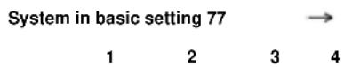
← Indicated on display
- Press keys 0, 7 and 7 for "Display group number 77" and confirm entry with Q key.
Note:
The engine must not be loaded during this diagnosis, if this occurs the diagnosis will be aborted and will not start again until the engine is revved-up.
Indicated on display: (1...4 = display zones)
If the diagnosis is initiated by the engine control module the display in display zone 4 jumps from "Test OFF" to "Test ON".
Note:
This process can take approx. 40 seconds.
- L eave engine running at idling speed until display zone 4 displays specification "Syst. OK."..
If "Syst. OK" appears in display zone 4:
- Press → key.
26-37
- Press keys 0 and 6 for function "End output" and confirm entry with Q key.
- Switch ignition off.
If "Syst.n.OK." appears in display zone 4:
- Press → key.
- Check DTC memory:
⇒ Repair Manual, 2.8 Liter VR6 4V Fuel Injection & Ignition, Engine Code(s) BDF, Repair Group 01
- Read readiness code:
⇒ Repair Manual, 2.8 Liter VR6 4V Fuel Injection & Ignition, Engine Code(s) BDF, Repair Group 01
- Generate readiness code again if DTC memory has been erased or engine control module disconnected from permanent positive supply:
⇒ Repair Manual, 2.8 Liter VR6 4V Fuel Injection & Ignition, Engine Code(s) BDF, Repair Group 01
If no DTC is stored in DTC memory:
- Press keys 0 and 6 for function "End output" and confirm entry with Q key.
- Switch ignition off.
- Check combi-valve Page 26-41.
26-38

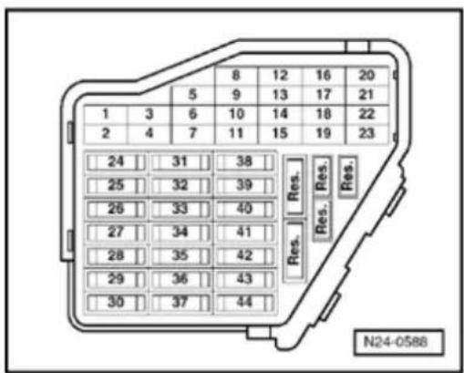
Secondary Air Injection (AIR) pump motor -V101-, checking
Special tools and equipment
◆ V.A.G 1551 Scan Tool (or vehicle system tester V.A.G 1552) with cable V.A.G 1551/3
Note:
All functions which could previously be performed with V.A.G 1551/1552 can also be performed with the tester VAS 5051.
Test conditions
- Fuses must be OK.
26-39
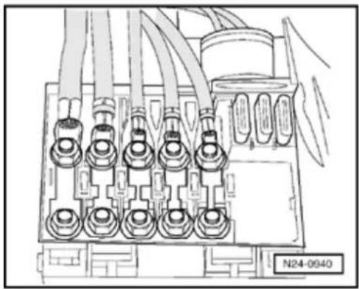
natural_image
Technical line drawing of an electrical connector with multiple terminal blocks and wiring (no text or symbols)
- Main fuses must be OK.
- Battery voltage must be at least 11.5 V.
- All electrical consumers, e.g. lights and rear window defroster must be switched off.
- If the vehicle is equipped with air conditioning, this must be switched off.
- Selector lever must be in position "P" or "N" on models with an automatic transmission.
- Intake and pressure hoses for secondary air injection pump motor not blocked or kinked
- Fuel Pump (FP) relay -J17- must be OK, checking:
⇒ Electrical Wiring Diagrams, Troubleshooting & Component Locations
- No DTCs may be stored in DTC memory:
⇒ Repair Manual, 2.8 Liter VR6 4V Fuel Injection & Ignition, Engine Code(s) BDF, Repair Group 01
26-40
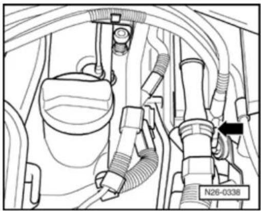
natural_image
Technical diagram of a vehicle engine compartment showing hoses and wiring (no text or symbols)Output Diagnostic Test Mode was aborted
Test sequence
- Remove engine cover.

- Disconnect pressure hose to combi-valve at coupling (arrow).
Note:
To release, press buttons together on hose coupling.
- Activate Secondary Air Injection (AIR) pump relay -J299- via output Diagnostic Test Mode (DTM):
⇒ Repair Manual, 2.8 Liter VR6 4V Fuel Injection & Ignition, Engine Code(s) BDF, Repair Group 01
Secondary air injection pump motor must run at intervals and air must exit at outlet of pressure hose.
If the motor runs, but little or no air exits:
- Press C key to abort output DTM.

Indicated on display
- Switch ignition off.
- Replace Secondary Air Injection (AIR) pump motor -V101- ⇒ Page 26-27, item 20.
If the secondary air injection pump motor does not run at intervals:
- Check activation of Secondary Air Injection (AIR) pump motor - V101-:
⇒ Repair Manual, 2.8 Liter VR6 4V Fuel Injection & Ignition, Engine Code(s) BDF, Repair Group 01
26-41

Combi-valve, checking
Special tools and equipment

♦ VAG 1390 Hand vacuum pump
Test conditions
• Vacuum lines and hose connections free of leaks.
- Pressure hose for secondary air injection pump motor not blocked or kinked.
• Vacuum lines not blocked or kinked.
• No DTC stored in DTC memory:
⇒ Repair Manual, 2.8 Liter VR6 4V Fuel Injection & Ignition, Engine Code(s) BDF, Repair Group 01
• Perform output Diagnostic Test Mode (DTM):
⇒ Repair Manual, 2.8 Liter VR6 4V Fuel Injection & Ignition, Engine Code(s) BDF, Repair Group 01
Test sequence
Note:
Do not use compressed air during the following check!
- Remove engine cover.
26-42
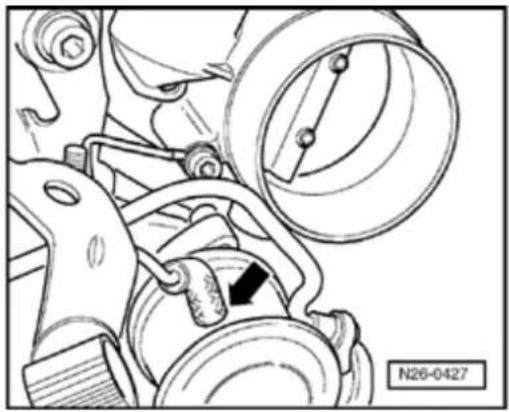
natural_image
Mechanical assembly diagram showing a belt drive mechanism with no visible text or symbols- Remove intake hose between Mass Air F (MAF) sensor and throttle valve control r
⇒ Repair Manual, 2.8 Liter VR6 4V Fuel Inj & Ignition, Engine Code(s) BDF, Repair Gr 24
- Pull vacuum hose off Secondary Air Injec (AIR) solenoid valve -N112- and combi-v (arrow).
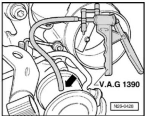


- Connect hand vacuum pump VAG 1390 f vacuum hose from combi-valve (arrow).
26-43
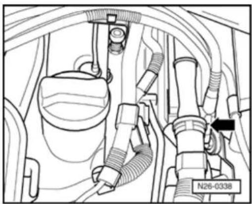
natural_image
Technical diagram of a vehicle engine compartment showing hoses and components (no readable text or symbols)
- Disconnect pressure hose to combi-valve at coupling (arrow) and blow in using light pressure. Combi-valve must be closed. - Operate hand vacuum pump. Combi-valve must open.
When the combi-valve does not open or is continuously open:
- Replace combi-valve Page 26-25, item - 5 -.
26-44
EVAP system, checking using KLI 9210 tester
Introduction
The KLI 9210 EVAP tester allows testing using nitrogen to pressurize the EVAP system and a smoke generator or ultrasonic tester to locate the source of EVAP system concerns.
This procedure is intended as a general guide for the use of the EVAP tester. EVAP systems vary between models.
Special tools and equipment
♦ VAS 5051 or VAS 5052 diagnostic tester
♦ KLI 9210 EVAP system tester (set to 14 in. H₂O)
◆ Light source (for viewing smoke)
◆ Special tool 3094 or equivalent
Using the KLI 9210 EVAP system tester ⇒ Tester operating instructions
26-45
Calibrating the KLI 9210 tester
Determine the vehicle leak threshold:
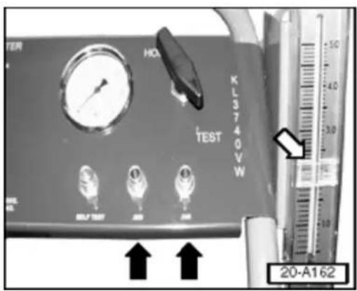
◆ Up to and including M.Y. 1999 leak threshold = 0.040 in.
◆ From M.Y. 2000 leak threshold = 0.0;
- Attach test hose to appropriate pre-set pc (black arrows).
- Turn control valve from "Hold" to "Test".
- Set flow meter flag (white arrow) at indicate value on flow meter.
- Turn control valve to "Hold"; remove test
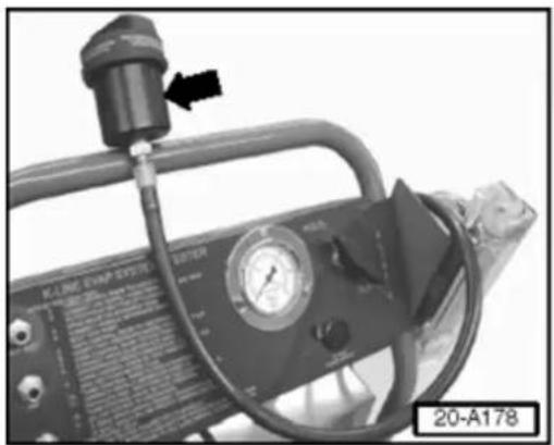
natural_image
Close-up of a gas pressure regulator device with pressure gauge and pipe fittings (no visible text or symbols)Testing the fuel cap
- Remove fuel cap.
- Connect fuel cap receiver (arrow) to hose
- Screw fuel cap tightly to cap receiver.
- Turn control valve to "Test" pressurizing (
- T urn valve to "Hold".
- Watch pressure gauge for drop in pressu 14 inches H_2O .
26-46
If no pressure drop is indicated:
- Proceed to "Checking Leak Detection Pu V144- for internal leaks".
If pressure drop is indicated:
- Replace fuel cap and re-test.
- Proceed to "Checking Leak Detection Pu V144- for internal leaks".
Checking Leak Detection Pump -V144- fc internal leaks
Basically, in the following procedure the EV system will be filled with smoke, the engine started and the LDP activated using the VA 5051 or VAS 5052. With the LDP activated, after clearing initial smoke away from the LI area using compressed air, the system is th filled with smoke again and rechecked for s at the LDP filter.
Conditions
- Ignition switched off
- LDP is visible Component Locations
- Tester hose connected to fuel filler neck
• VAS 5051 or VAS 5052 Diagnostic tool connected to vehicle
• Smoke generator connected to battery - Turn KLI 9210 valve to "Test" and use sm generator trigger to fill system with smoke until smoke is coming out of the LDP filter
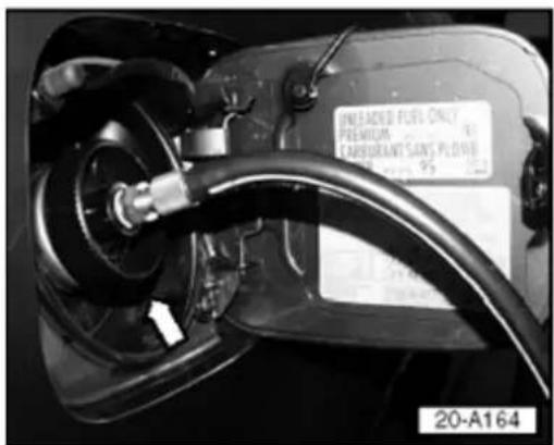
26-47
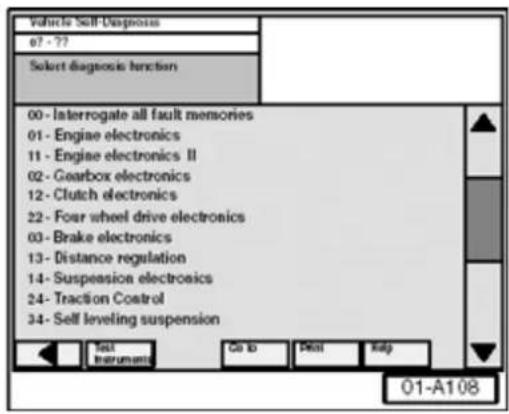
- Start engine.
- From VAS 5051 Startup screen, select "self diagnosis".
- Select vehicle system "01 - Engine electr
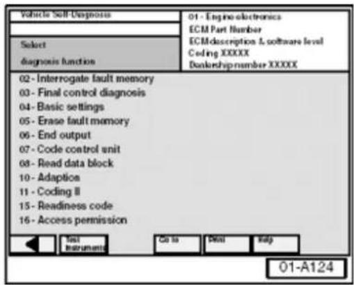
- Select Diagnosis Function "04 - Basic set
26-48
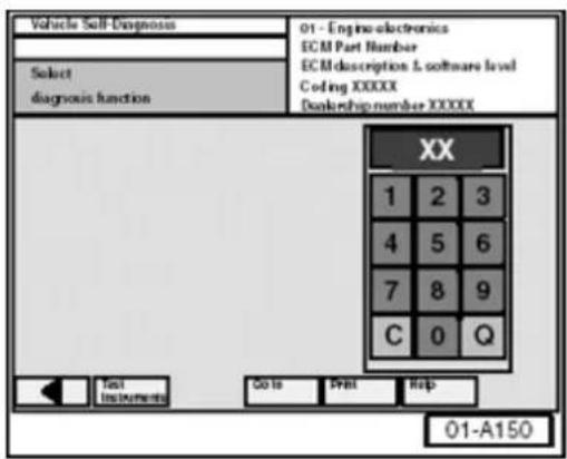
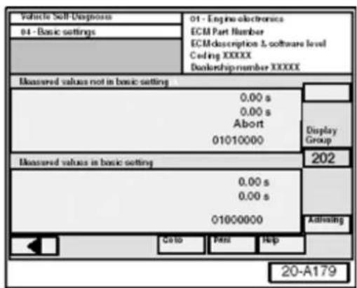

- Input appropriate display group from table below on keypad.
| Engine code | Display group |
| AEB, AEG, AFP, AHA, APH, ATQ, ATW, AUG, AWD, AWM, AWP, AWV, AWW, BDC, BDF, BEV, BGD, BGJ | 071 |
| AVH, AZG, BAP, BBW, BDP | 202 |
- Press "Q" on keypad to confirm. LDP should activate
If LDP does not activate:
For some vehicles using Display group 202 a similar screen appears indicating "Test Off".

- Select "Activating" button.
If LDP does not activate:
- Check electrical connections to LDP.
- Check vacuum source to LDP.
If LDP activates:
26-49
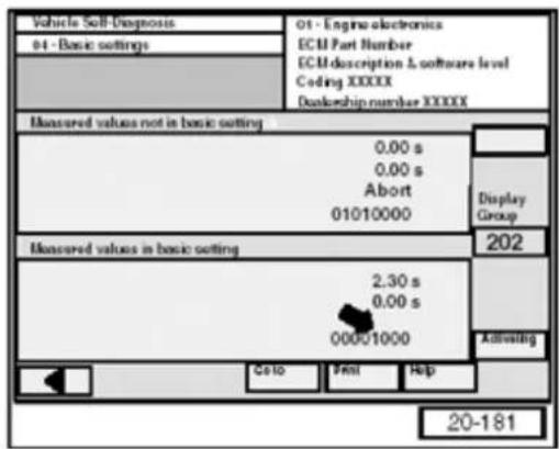
A similar screen appears, Test is "ON" (indicated by a "1" in position 5, -arrow-).
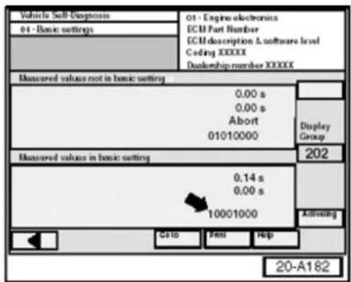
Position 1 -arrow- alternates between "0" and "1" during pump operation.
26-50
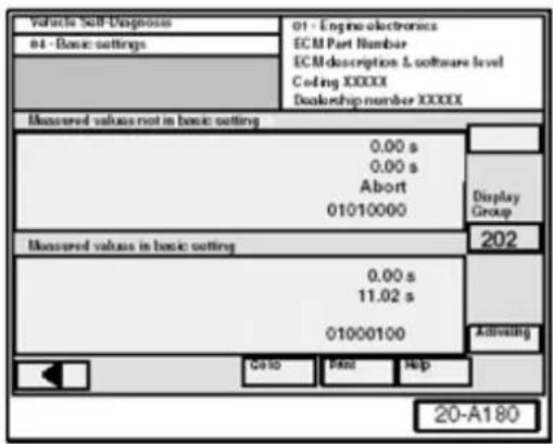
If test is OK:
Indicated by "1" in position 6 and a "0" in position 8 as shown.
LDP has activated and the system is pressurized.
- Using a compressed air blow gun, clear area near LDP and LDP filter of any residual smoke.
If the test aborts and DTCs other than for small or large leaks are stored:
- Check and repair according to DTC listed in DTC table for appropriate engine code.
When "Check end" is indicated on VAS 5051 or VAS 5052:
Note:
Only check LDP during "Check end" phase when "Test OK" was indicated.
- Use smoke generator trigger to fill system with smoke again.
- Check for smoke doming from LDP filter and LDP hose connections.
◆ Smoke coming from filter indicates a faulty LDP
◆ Smoke coming from LDP outlet or hose indicates a faulty hose or clamp
26-51
- Make repairs as necessary and check with smoke again.
◆ No smoke coming from filter indicates is OK and leak is somewhere else in system
Note:
If the KLI 9210 EVAP system tester is connected in "Test" mode and Basic settings (using Se Diagnosis) and Fault finding are activated, a false "System OK" message may be generated.
If the LDP is OK and a DTC was stored for EVAP system:
- Switch ignition off.
- Continue checking EVAP system as follo
Checking EVAP system for leaks
- Clamp off LDP outlet (EVAP side) -1- usi special tool 3094 or equivalent.
CAUTION!
Clamp only soft rubber lines when isolate leak. To avoid risk of damage, never clam plastic lines!
- Turn control valve from "Hold" to "Test".
- Allow fuel system to pressurize.
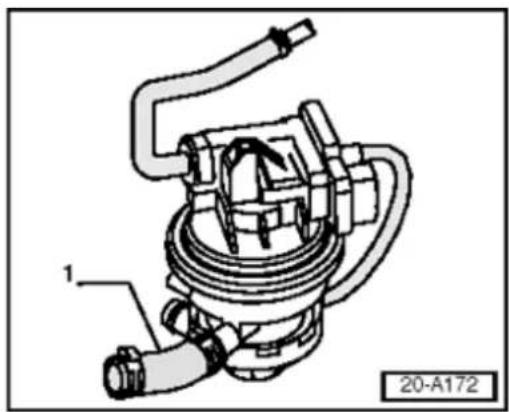
natural_image
Technical line drawing of a mechanical device with labeled component (1), no readable text or symbols beyond part number and label26-52
Note:
Fuel system pressurization depends on volume of fuel system and amount of fuel in tank.
If fuel system pressurization does not stabilize:
- Verify that all fuel system outlets have been sealed before continuing.
Note:
Any flow shown on flow meter indicates a leak. Flow below flow meter flag set at vehicle leak standard may indicate a sporadic DTC.
If flow meter on tester registers flow near or above pre-set pressure:
- Clamp off hose leading from EVAP canister purge regulator valve -N80- to intake manifold.
If flow stops:
- Replace EVAP canister purge regulator valve - N80- and repeat test before continuing.
If meter indicates no flow after test:
- Perform quality check and return vehicle to customer.
If flow continues:
- Use smoke generator trigger to charge fuel system with smoke again.
26-53
- Inspect complete EVAP system for escape smoke.
Note:
It may be necessary to move, twist, or wigg. EVAP components around to reproduce lea
If leak cannot be found using smoke:
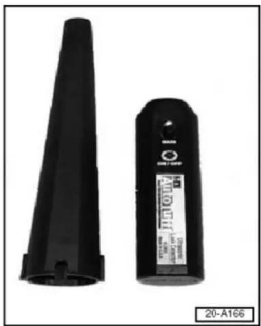
natural_image
Two black plastic spray cans, one tall and one with a label showing '20-A166' (no visible text on the cans themselves)
- L ocate leak with ultrasonic tester.
◆ General search: tester only
◆ Localized search: tester with extension wand (left)
If leak cannot be located:
- Disconnect and plug or clamp shut EVAF to isolate fuel tank using special tool 3094 equivalent before continuing.
CAUTION!
Clamp only soft rubber lines when isolate leak. To avoid risk of damage, never clam plastic lines!
If flow stops:
- Reconnect EVAP lines and search area t isolated.
When leak has been located:
- Repair leak and repeat EVAP system tes
26-54
Note:
Because leak may be at top of fuel tank, it may not be possible to locate through fuel pump/sending unit access plate.
♦ Lower fuel tank if necessary to locate leak.
CAUTION!
Do not return vehicle to the customer without having performed a proper diagnosis and repair.
Select a topic
01 - On Board Diagnostic (OBD)
On Board Diagnostic (OBD)
On Board Diagnostic (OBD) features Electronic Power Control (EPC) Warning Light -K132- Malfunction Indicator Light (MIL) -K83- On Board Diagnostic (OBD), technical data VAG 1551 and Motronic Engine Control Module (ECM) -J220-, connecting and selecting VAS 5051 and Motronic Engine Control Module (ECM) -J220-, connecting and selecting
DTC memory
DTC memory, checking and erasing Automatic test sequence
DTC table: SAE P0 codes
DTCs P0010 to P0704, VAG 16394 to 17088
DTC table: SAE P1 codes
DTCs P1047 to P1912, VAG 17455 to 18322
DTC table: SAE P2 codes
DTCs P2101 to P2138, VAG 18533 to 18570
DTC table: SAE P3 codes
DTCs P3211 to P3266, VAG 19667 to 19722
Output Diagnosis Test Mode (DTM)
Output Diagnosis Test Mode (DTM), performing
Readiness code
Function Read readiness code Generating readiness code Readiness code, generating (overview)
Measured value (data) blocks
Safety precautions Read measured value (data) block Measured value blocks, display groups 0...9 - Basic functions, evaluating Measured value blocks, display groups 10...29 - Ignition, evaluating Measured value blocks, display groups 30...33, 99 - Oxygen Sensor (O2S) control, evaluating Measured value blocks, display groups 50...69 - Speed control, Evaluating Measured value blocks, display groups 70...77 - Reducing emissions, evaluating Measured value blocks, display groups 86...89, 100 - Readiness code, evaluating Measured value blocks, display groups 90...96 - Performance
improvement, evaluating
Measured value blocks, display groups 120...129 - Communication, evaluating
24 - Multiport Fuel Injection (MFI)
Fuel injection system, servicing
Component locations overview
Fuel injection system, general notes
Fuel injection system components, removing and installing
Intake manifold, disassembling and assembling
Fuel rail, disassembling and assembling
Air cleaner assembly, disassembling and assembling
Safety precautions
Rules for cleanliness
Technical data
Components, checking
Heated Oxygen Sensor (HO2S), checking
Oxygen Sensor (O2S) heating for Oxygen Sensor (O2S) Behind
Three Way Catalytic Converter (TWC) -G130-, checking
Mass Air Flow (MAF) sensor -G70-, checking
Throttle Valve Control Module -J338-, checking
Engine Coolant Temperature (ECT) sensors -G62- and -G2-, checking
Intake Air Temperature (IAT) sensor -G42-, checking
Engine Speed (RPM) Sensor -G28-, checking
Fuel injectors, checking
Fuel injectors, checking for leaks and quantity injected
Residual pressure and fuel pressure regulator, checking
Intake Manifold Change-Over Valve -N156-, checking
Intake Air system, leak testing
Functions, checking
Idle speed check
Oxygen Sensor (O2S) and Oxygen Sensor control before Three Way
Catalytic Converter (TWC), checking
Oxygen Sensor (O2S) and Oxygen Sensor control after Three Way
Catalytic Converter (TWC), checking
Heated Oxygen Sensor (HO2S), checking aging
Oxygen Sensor (O2S) Behind Three Way Catalytic Converter (TWC)
-G130-, checking aging
Engine operating mode, checking
Motronic Engine Control Module (ECM) -J220-
Function
Engine Control Module (ECM) voltage supply, checking
"Voltage supply open circuit," followup procedure
Motronic Engine Control Module (ECM) -J220-, replacing
Motronic Engine Control Module (ECM) -J220-, coding
Motronic Engine Control Module (ECM) -J220-, coding variations
Motronic Engine Control Module (ECM) -J220- to Throttle Valve
Control Module -J338-, matching
Additional signals, checking
Vehicle Speed Signal, checking
A/C compressor signal, checking
Signal from Clutch Vacuum Vent Valve Switch -F36-, checking
Brake Light Switch -F- and Brake Pedal Switch (cruise control/Diesel Direct Fuel Injection -F47- signal, checking
Transmission Range signal, checking
Cruise Control System (CCS), checking
CAN-bus, checking
28 - Ignition/Glow plug system
Ignition system, servicing
General notes on ignition system
Ignition system components, removing and installing Safety precautions
Test Data, Spark plugs
Camshaft Position (CMP) Sensor, checking
Ignition coil with power output stage, checking
Knock sensor, checking
Misfire detection, checking
On Board Diagnostic (OBD)
On Board Diagnostic (OBD) features
The Motronic Engine Control Module (ECM) -J220- is equipped with a DTC memory.
If Diagnostic Trouble Codes (DTCs) occur in the sensors and components being monitored, they will be stored in the DTC memory together with an indication of the type of malfunction.
After evaluating the information the Motronic Engine Control Module (ECM) -J220-decides between the different Diagnostic Trouble Codes (DTCs) DTC table from Page 01-30 and stores these until the contents of the DTC memory are erased.
Diagnostic Trouble Codes (DTCs) which only occur sporadically will have the addendum "sporadic fault" on the print out. These Diagnostic Trouble Codes (DTCs) will be indicated on the display by the addendum "/SP". The cause of sporadic Diagnostic Trouble Codes (DTCs) can be e.g. a loose terminal or a brief open circuit. If a "sporadic malfunction" does not occur again within 40 warm-up phases (engine start below 50^ coolant temperature - switched off above 72^ ), it will be erased from the DTC memory.
The Diagnostic Trouble Codes (DTCs) stored can be read-out with the VAG 1551 scan tool, the vehicle system tester VAG 1552 or the vehicle diagnostic, testing and information system VAS 5051 Page 01-23.
01-2
The DTC memory must be erased after the malfunction(s) have been repaired Page 01-23 and the readiness code must be regenerated Page 01-149.
All Motronic Engine Control Module (ECM) - J220- learned values will be erased when the Motronic Engine Control Module (ECM) -J220- connector is pulled off or the battery is disconnected. However the contents of the DTC memory are retained. When the engine is subsequently started the idling could be rough for a brief period. In this case leave the engine running for a few minutes at idle or perform a longer road test, until the learning process is completed. Procedure after voltage supply has been interrupted Page 24-170.
Note:
General information for On Board Diagnosis (OBD) can be found in the instruction manuals for the VAG 1551 scan tool, vehicle system tester VAG 1552 or VAS 5051.
01-3
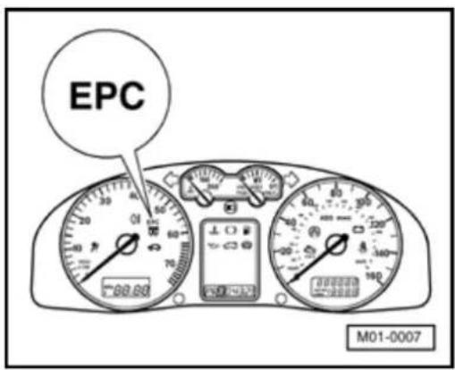
Electronic Power Control (EPC) Warning Light -K132-
"EPC" is the abbreviation for Electronic Power Control.
Location of Electronic Power Control (EPC) Warning Light -K132-
When the ignition is switched on the Motronic Engine Control Module (ECM) -J220- checks all components which are important for the correct functioning of the Electronic Power Control.
If malfunctions are detected in Electronic Power Control system when the engine is running, the Motronic Engine Control Module (ECM) -J220- will switch on the Electronic Power Control (EPC) Warning Light -K132-. (Diagnostic Trouble Codes (DTCs) are identified accordingly in the DTC table). Simultaneously an entry is made in the Motronic Engine Control Module (ECM) -J220- DTC memory.
Functional check:
- Switch on ignition:
Electronic Power Control (EPC) Warning Light -K132- must light-up.
If the Electronic Power Control (EPC) Warning Light -K132- does not light-up with ignition switched on:
- Check instrument cluster and Electronic Power Control (EPC) Warning Light -K132:-
⇒ Repair Manual, Electrical Equipment On Board Diagnostic (OBD), Repair Group 01
01-4
If the Electronic Power Control (EPC) Warning Light -K132- lights up with ignition switched on:
- Start engine and run at idle:
The Electronic Power Control (EPC) Warning Light -K132- must go out after several seconds.
If the Electronic Power Control (EPC) Warning Light -K132- does not go out:
- Check DTC memory, repair Diagnostic Trouble Codes (DTCs) if necessary and then erase DTC memory Page 01-23DTC memory, checking and erasing.
- Read off readiness code Page 01-146. If the DTC memory has been erased or the Motronic Engine Control Module (ECM) -J220- was disconnected from battery (B+) positive, the readiness code must be generated again Page 01-149.
01-5
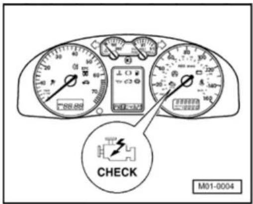
Malfunction Indicator Light (MIL) -K83-
If the Motronic Engine Control Module (ECM) -J220- detects a malfunction this is indicated by switching the Malfunction Indicator Light (MIL) on.
Location of Malfunction Indicator Light (MIL)
Note:
The Malfunction Indicator Light (MIL) can switch on in the continuous or flashing mode. Always check DTC memory Page 01-23.
- Flashing mode: There is a malfunction present which can damage the Three Way Catalytic Converter (TWC) when continuing to drive at this power output. If this occurs, continue driving only at reduced output.
Continuous mode: There is a malfunction present which causes the emissions to deteriorate. check engine or transmission control module in this case.
Check the DTC memory if the customer has a complaint or there is a driveability problem and the Malfunction Indicator Light (MIL) does not light up, this is because Diagnostic Trouble Codes (DTCs) can be stored which will not switch the Malfunction Indicator Light (MIL) on immediately.
Functional check:
- Switch on ignition:
Malfunction Indicator Light (MIL) must light-up.
If the Malfunction Indicator Light (MIL) does not light-up with ignition switched on:
- Check instrument cluster and Electronic Power Control (EPC) Warning Light -K132-:
⇒ Repair Manual, Electrical Equipment On Board Diagnostic (OBD), Repair Group 01
If the Malfunction Indicator Light (MIL) lights-up with ignition switched on:
- Start engine and run at idle:
Malfunction Indicator Light (MIL) must go out after several seconds.
If the Malfunction Indicator Light (MIL) does not go out:
- Check DTC memory, repair Diagnostic Trouble Codes (DTCs) if necessary and then erase DTC memory Page 01-23DTC memory, checking and erasing.
- Read off readiness code Page 01-146. If the DTC memory has been erased or the Motronic Engine Control Module (ECM) -J220- was disconnected from battery (B+) positive, the readiness code must be generated again Page 01-149.
01-7
On Board Diagnostic (OBD), technical data
Control module identification
The control module version is displayed when the VAG 1551 scan tool, the vehicle system tester VAG 1552 or the vehicle diagnostic, testing and information system VAS 5051 is connected and Engine Control Module (ECM) selected Page 01-12.
Equipment
| Engine code | BDF |
| System designation | M |
| Exhaust emissions fulfil | LEV^1) |
| On Board Diagnosis (OBD) | OBD II |
| Output Diagnostic Test Mode (DTM) | yes |
| Method of data transfer to VAG 1551/1552 | Rapid data transfer |
| DTC memory | Non-volatile memory^2) |
| Memory for learned values | Volatile memory^3) |
otronic ME7.1.1
1) LEV = Low Emission Vehicles (exhaust emissions max. 0.075 g/mi HC).
2) Independent of voltage supply.
3) All values are erased when voltage supply is interrupted.
01-8
| Engine code | BDF |
| Oxygen Sensor control | 2 sensors |
| Knock control | 2 knock sensors |
| Three Way Catalytic Converter (TWC) | yes |
| Exhaust gas recirculation | n |
| Charging | no |
| Secondary air system | yes |
| Electronic Power Control | yes |
| Variable intake manifold | yes |
| Variable valve timing | yes^4) |
0
4) Two independently variable camshafts.
01-9
Functions which can be selected when using the VAG 1551/1552 or VAS 5051 scan tools
The prerequisites to select the desired functions can be found in the following table.
| Function | Prerequisite | |||
| Functions on VAG 1551/1552 or on VAS 5051 | Engine not running, ignition switched on | Engine running at idle | Vehicle being driven | |
| 01 | Check control module version1) | yes | yes | yes |
| 02 | Check DTC memory | yes2) | yes | yes |
| 03 | Output Diagnostic Test Mode (DTM) | yes | n | o |
| 04 | Basic setting3) | yes4) | yes | yes |
| 05 | Erase DTC memory | yes | no | no |
| 06 | End output | yes | yes | yes |
| 07 | Code control module | yes | no | no |
| 08 | Read measured value block | yes | yes | yes |
| 10 | Adaption | yes | no | no |
| 15 | Read readiness code | yes | yes | yes |
1) Function can not be selected with VAS 5051.
2) Only perform with ignition switched on, when engine does not start (operate starter for at least 6 seconds first).
^3) Must be carried out after performing the following work: Replacing Motronic Engine Control Module (ECM) -J220-, Throttle Valve Control Module or engine, or disconnecting battery.
4) When adapting Throttle Valve Control Module
01-10
Selecting functions (mode) via address word 33, CARB / OBD II
| Function | Prerequisite | |||
| Functions on VAG 1551/1552 or on VAS 5051 | Engine not running, ignition switched on | Engine running at idle | Vehicle being driven | |
| Mode 1 | Transfer of diagnostic data | yes | yes | yes |
| Mode 2 | Transfer of operating conditions | yes | yes | yes |
| Mode 3 | Check DTC memory | yes | yes | yes |
| Mode 4 | Erase DTC memory (diagnostic data) | yes | n | o |
| Mode 5 | Output of Oxygen Sensor signals | yes | yes | yes |
| Mode 6 | Transfer of measured values | yes | yes | yes |
| Mode 7 | Check DTC memory | yes | yes | yes |
| Mode 8 | Test of tank system | no | yes | no |
Note:
◆ Individual measured values can be read out in Mode 1. Mode 1 is not recommended for VW dealerships as this data can be more accurately read under 01/function 04 or function 08.
◆ Mode 2 displays the operating conditions under which the malfunction was detected.
With Mode 3 the DTC memory can be checked and with Mode 4 the DTC memory (diagnostic data) can be erased.
01-11
Under Mode 5 the static magnitude of the Oxygen Sensor (O2S) (required by the legislator) can be displayed As this magnitude does not have any significance with reference to the Oxygen Sensor (O2S) diagnosis, Mode 5 is of no significance for a VW dealership.
Under Mode 6, all the measured values of components and systems, which are not continuously monitored, can be checked.
With Mode 7, Diagnostic Trouble Codes (DTCs) can be checked which have not caused the Malfunction Indicator Light (MIL) to light up (MIL is not switched on, no Diagnostic Trouble Codes (DTCs) under Mode 3).
Under Mode 9, a check of the software check total and control module identification is made.
01-12

VAG 1551 and Motronic Engine Control Module (ECM) -J220-, connecting and selecting
Special tools, workshop equipment, testers, measuring instruments and auxiliary items required

◆ VAG 1551 scan tool
Note:
The vehicle system tester VAG 1552 can be used instead of the VAG 1551 scan tool, however a print-out is not possible.
All functions of VAG 1551/1552 can also be carried out with the vehicle diagnostic, testing and information system VAS 5051. Connecting VAS 5051 Page 01-18.

◆ VAG 1551/3 Adapter cable
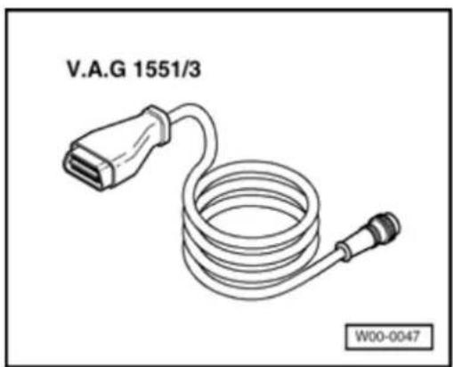
natural_image
Line drawing of a V.A.G 1551/3 cable with connector, no text or symbols on the diagram itself01-13
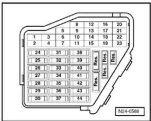

natural_image
Electrical connector diagram showing multiple terminal blocks with wires (no text or symbols)Test prerequisites

• The fuses must be OK.

• The main fuses must be OK.
- The battery voltage must be at least 11.5 V.
• Ground (GND) connection between engine and body must be OK.
- All electrical devices, e.g. lights and rear window heating must be switched off.
- If the vehicle is equipped with air conditioning, it must be turned off.
- Selector lever must be in position "P" or "N" on vehicles with an automatic transmission.
01-14

Work sequence

- Connect VAG 1551 scan tool ((VAG 1552) with cable VAG 1551/3.
After the scan tool has been connected, depending upon desired function:
- Switch ignition on or Start engine Page 01-9, Table "Selectable functions".
Note:
◆ If the display remains blank, check voltage supply for DLC:
⇒ Electrical Wiring Diagrams, Troubleshooting & Component Locations
◆ If the display does not indicate as described in the work sequence:
⇒ Scan tool operating instructions
If due to an input malfunction "Fault in the data transfer!" is displayed, pull wire off scan tool, reconnect and repeat work step.
01-15
VAG SELF-DIAGNOSIS
1 - Rapid data transfer*
2 - Flash code output*

- Operate scan tool taking into account the information on display:
Indicated on display:
* Appears alternately
- O perate scan tool, taking into account the information on display:
- Press button -1- for "Rapid data transfer".
- Press buttons -0- and -1- for address word "Engine electronics" and confirm entry with -0 button.
022906032BL MOTRONIC ME7.1.1 G 0006 →
Coding 00032
WSC 00000

The control module identification and coding are shown on the display, e.g.:
◆ 022 906 032 BL = Part No. of the control module (for latest control module version:)
⇒ Parts catalog
♦ MOTRONIC ME7.1.1 = System designation (Motronic)
◆ G = Cruise control system (CCS) activated
◆ 0006 = Program level number
01-16
◆ Coding 00032 = control module coding, coding variants of Motronic Engine Control Module (ECM) -J220- ⇒ Page 24-181.
◆ WSC 00000 = Workshop code of VAG 1551 with which the last coding was carried out. (If the factory coding has not been changed, WSC 00000 appears)
Note:
Replace control module if the control module version displayed does not correspond to the vehicle Page 24-173.
A wrong coding of the Engine Control Module results in:
◆ Engine running Diagnostic Trouble Codes (DTCs) (gear change jerks, load change jerks, etc.)
◆ Increased fuel consumption
♦ Increased exhaust gas emissions
◆ Diagnostic Trouble Codes (DTCs) stored in DTC memory which are not actually present (false DTCs)
◆ Functions will not be performed (Oxygen Sensor (O2S) control, activation of the Evaporative Emissions (EVAP) Canister system, etc.).
◆ Reduced service life of transmission
01-17
If the coding differs from the vehicle version, then:
- Check control module coding Page 24-177, coding Motronic Engine Control Module (ECM) - J220-.
- Press → -button.
Rapid data transfer Select function XX
HELP

Indicated on display:
- See repair procedures for further measures.
01-18
VAS 5051 and Motronic Engine Control Module (ECM) -J220-, connecting and selecting
All functions which could previously be performed with VAG 1551/1552 can also be performed with the vehicle diagnostic, testing and information system VAS 5051 in the operating mode vehicle On Board Diagnosis (OBD):
⇒ Operating instructions for Vehicle Diagnosis, Testing and Information System VAS 5051.
Special tools, workshop equipment, testers, measuring instruments and auxiliary items required
♦ VAS 5051 Vehicle Diagnosis, Testing and Information System

natural_image
Line drawing of a V.A.G 1551/3 cable with connector port and connector end (no text or symbols on the diagram itself)◆ Diagnostic cable VAS 5051/1 or VAS 5051/3
01-19


natural_image
Electrical terminal block diagram with multiple connectors and wiring (no text or symbols visible)Test prerequisites

• The fuses must be OK.

• The main fuses must be OK.
- The battery voltage must be at least 11.5 V.
• Ground (GND) connection between engine and body must be OK.
- All electrical devices, e.g. lights and rear window heating must be turned off.
- If the vehicle is equipped with air conditioning, it must be turned off.
- Selector lever must be in position "P" or "N" on vehicles with an automatic transmission.
01-20
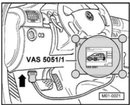
Work sequence
- Connect VAS 5051 using VAS 5051/1 or 5051/3 diagnostic adapter cable as follow
- Connect connector of diagnostic adapter onto DLC.
- Depending upon desired function: Switch ignition on or Start engine Page 01-9, "Selectable functions".
Note:
In the functions 04 - Basic setting or 08 measured value (data) block, the display will be listed from top to bottom.
◆ If the display does not indicate as descri the work sequence:
⇒ Operating instructions for VAS 5051.
01-21
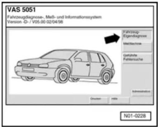
Indicated on display:
Select operating mode:
- Press button on screen for "Vehicle self-diagnosis".
Indicated on display:
Select vehicle system:
- Press button "01 - Engine electronics" on screen.
01-22
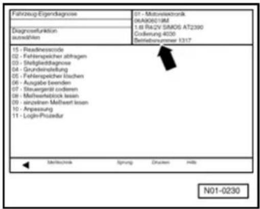
The control module identification and coding are shown on the display, e.g.:
If the coding differs from the vehicle version, then:
- Check control module coding Page 24-177, Coding Motronic Engine Control Module (ECM) - J220-.
Indicated on display:
Select diagnostic function:
At this point all diagnostic functions are available.
- Press desired function on the display.
- See repair procedures for further measures.
DTC memory
Check DTC memory of all control modules Page 01-27, Automatic test sequence.
DTC memory, checking and erasing
Special tools, workshop equipment, testers, measuring instruments and auxiliary items required

◆ VAG 1551 scan tool (or VAG 1552 vehicle system tester) with VAG 1551/3 adapter cable
Note:
All functions which could previously be performed with VAG 1551/1552 can also be performed with VAS 5051.

Test prerequisites
• The fuses must be OK.
01-24
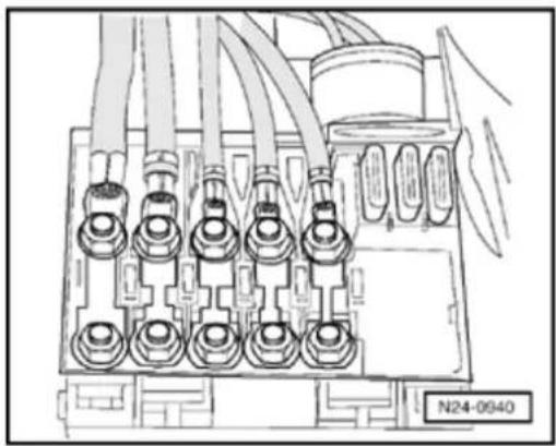
natural_image
Technical line drawing of an electrical connector with multiple ports and wiring (no text or symbols)
• The main fuses must be OK.
- The battery voltage must be at least 11.5 V.
• Ground (GND) connection between engine and body must be OK.
- All electrical devices, e.g. lights and rear window heating must be turned off.
- If the vehicle is equipped with air conditioning, it must be turned off.
- Selector lever must be in position "P" or "N" on vehicles with an automatic transmission.
Work sequence
- Connect VAG 1551 scan tool (or VAG 1552) and select Engine Control Module (ECM) with the "Address word" 01. When doing this the engine must be running at idle: (Connecting scan tool and selecting Engine Control Module (ECM) Page 01-12).
Note:
Only when engine does not start:
- Operate starter for approx. 6 seconds. Then do not switch the ignition off.
01-25
| - Switch on scan tool printer with the print button.Warning light in button must light up. | ||
| Rapid data transfer | HELP | Indicated on display: |
| Select function XX | - O perate scan tool, taking into account information on display:- Press buttons -0- and -2- for function "Check DTC memory" and confirm entry with -Q- button. | |
| X Diagnostic Trouble Codes (DTCs) detected! | The number of Diagnostic Trouble Codes (DTCs) stored or "No malfunction detected!" will be shown on the display.Note:If no DTC is stored:- Press the → -button.If one or more Diagnostic Trouble Codes (DTCs) are stored:The stored Diagnostic Trouble Codes (DTCs) will be displayed and printed out one after the other. | |
| Rapid data transfer | HELP | After the stored Diagnostic Trouble Codes (DTCs) have been printed out, the display will show: |
| Select function XX |
01-26
- Press buttons -0- and -5- for the function "Erase DTC memory" and confirm entry with -Q- button.
Rapid data transfer
DTC memory is erased!

Indicated on display:
Note:
If the ignition is switched off between "Check DTC memory" and "Erase DTC memory" the DTC memory will not be erased.
- Press → -button.
Rapid data transfer
Select function XX

Indicated on display:
- Press buttons -0- and -6- for the function "End output" and confirm entry with -Q- button.
Repair Diagnostic Trouble Codes (DTCs) printed out using DTC table:
◆ SAE P0 codes ⇒ Page 01-30,
◆ SAE P1 codes ⇒ Page 01-58,
◆ SAE P2 codes ⇒ Page 01-98,
♦ SAE P3 codes ⇒ Page 01-99.
- Read readiness code Page 01-146. If the DTC memory has been erased or the Motronic Engine Control Module (ECM) -J220- was disconnected from battery (B+) positive, the readiness code must be generated again Page 01-149.
01-27

Automatic test sequence
Special tools, workshop equipment, testers, measuring instruments and auxiliary items required
◆ VAG 1551 scan tool (or vehicle system tester VAG 1552) with VAG 1551/3 adapter cable
Note:
All functions which could previously be performed with VAG 1551/1552 can also be performed with the vehicle diagnostic, testing and information system VAS 5051.
01-28
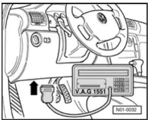
Work sequence

- Connect VAG 1551 scan tool (or VAG 1552) using VAG 1551/3 adapter cable.
During test and assembly work Diagnostic Trouble Codes (DTCs) can be detected from other control modules like e.g. connector disconnected. Therefore on completion the DTC memories of all control modules must be checked and erased. To do this:
- Press button -0- twice for address word "Automatic test sequence" and confirm entry with -Q- button. VAG 1551 transmits all known address words one after another.
When a control module answers with its identification the number of stored Diagnostic Trouble Codes (DTCs) appears on the display or "No fault detected".
Any system Diagnostic Trouble Codes (DTCs) that are stored will be displayed one after the other and printed out. The VAG 1551 will then transmit the next address word.

The automatic test sequence has ended when following is indicated on display:
- Erase all DTC memories and then perform a road test.
Observe the valid safety precautions when performing a road test Page 01-182.
Rapid data transfer
HELP
Select function XX
01-29
During the road test the following operating conditions must be fulfilled:
◆ The coolant temperature must exceed 85 °C.
When the temperature is reached, the operating conditions Idling, Part throttle, Wide open throttle, Overrun must be attained several times.
- At wide open throttle the speed must exceed 3500 rpm.
- Again check DTC memories of all control modules using "automatic test sequence".
If no DTC is stored:
- Press → -button.
Rapid data transfer Select function XX
HELP

Indicated on display:
- Press buttons -0- and -6- for function "End output" and confirm entry with -Q- button.
- Switch off ignition.
DTC table: SAE P0 codes
Note:
◆ The DTC code overview is listed according to SAE or VAG code.
Electronic Power Control "EPC" relevant Diagnostic Trouble Codes (DTCs) are indicated additionally by the Electronic Power Control (EPC) Warning Light -K132- in the instrument cluster.
♦ Explanation of the Malfunction types (e.g. "open circuit/short to Ground"):
⇒ scan tool operating instructions
If components are indicated as faulty: First check the wiring and connectors to these components as well as the system Ground (GND) connections referring to Electrical Wiring Diagrams. If no malfunction can be located, replace component. This is particularly relevant if Diagnostic Trouble Codes (DTCs) are output as "occurring sporadically" (SP).
◆ Erase DTC memory after repairing malfunction ⇒ Page 01-23 and generate readiness code again ⇒ Page 01-149.
VAG 1551 print out, e.g.:
16497 P0113 035 Intake Air Temperature (IAT) sensor -G42- Signal too high, Sporadic malfunction
Explanation:
◆ 16497 = DTC code
◆ P0113 = Additional DTC code
◆ 035 = Malfunction type as a number
◆ Intake Air Temperature (IAT) Sensor -G42-- = faulty circuit or malfunction location
◆ Signal too high = Malfunction type as text
♦ Sporadic Diagnostic Trouble Codes (DTCs) = Diagnostic Trouble Codes (DTCs) that are not always present e.g. loose terminal
01-31
Explanation of SAE Diagnostic Trouble Codes (DTCs):
System type:
◆ Pxxxx = Diagnostic Trouble Codes (DTCs) for the drive
Standardized code:
◆ P0xxx = Defined Diagnostic Trouble Codes (DTCs) with standardized DTC text according to SAE
◆ P1xxx = Supplementary emissions relevant Diagnostic Trouble Codes (DTCs) provided by manufacturer
◆ P2xxx = Defined Diagnostic Trouble Codes (DTCs) with standardized DTC text according to SAE, as of model year 2000
◆ P3xxx = Supplementary emissions relevant Diagnostic Trouble Codes (DTCs) provided by manufacturer, as of model year 2000
System group:
◆ Px0xx = Fuel and air measurements and supplementary exhaust gas control
◆ Px1xx = Fuel and air measurements
◆ Px2xx = Fuel and air measurements
◆ Px3xx = Ignition system
◆ Px4xx = Supplementary exhaust gas control
◆ Px5xx = Speed and idling control
◆ Px6xx = Control module and output signals
◆ Px7xx = Transmission
◆ Px8xx = Transmission
◆ Px9xx = Control module, input and output signals
01-32
DTCs P0010 to P0704, VAG 16394 to 17088
Fuel and air measurements and supplementary exhaust gas control
| DTC code | DTC text | Corrective action | |
| SAE | VAG | ||
| P0010 | 16394 | Bank 1 camshaft timing adjustmentMalfunction | - Check camshaft timing adjustment valve ⇒ Page 01-100, Output Diagnosis Test Mode (DTM)- Check camshaft timing adjustment:⇒ Repair Manual, 2.8 Liter VR6 4V Engine Mechanical, Engine Code(s): BDF; Repair Group 15- Check timing:⇒ Repair Manual, 2.8 Liter VR6 4V Engine Mechanical, Engine Code(s): BDF; Repair Group 15 |
| P0011 | 16395 | Bank 1, Camshaft retarded positionSpecification not reached | |
| P0012 | 16396 | Bank 1, Camshaft advanced positionSpecification not reached | |
| P0014 | 16398 | Bank 1 camshaft retarded positionExhaust specification not reached | |
| P0015 | 16399 | Bank 1 camshaft advanced positionExhaust specification not reached | |
01-33
| DTC code | DTC text | Corrective action | |
| SAE | VAG | ||
| P0030 | 16414 | Bank 1, sensor 1 heating element circuitOpen circuit | - Check Oxygen Sensor (O2S) heating before Three Way Catalytic Converter (TWC) ⇒ Page 24-38- Check Oxygen Sensor (O2S) and Oxygen Sensor (O2S) control before Three Way Catalytic Converter (TWC) ⇒ Page 24-131 |
| P0031 | 16415 | Bank 1, sensor 1 heating element circuitShort to Ground (GND) | |
| P0032 | 16416 | Bank 1, sensor 1 heating element circuitShort to positive | |
| P0036 | 16420 | Bank 1, sensor 2 heating element circuitOpen circuit | - Check Oxygen Sensor (O2S) heating for Oxygen Sensor (O2S) after Three Way Catalytic Converter (TWC) ⇒ Page 24-45- Check Oxygen Sensor (O2S) and Oxygen Sensor (O2S) control after Three Way Catalytic Converter (TWC) ⇒ Page 24-140 |
| P0037 | 16421 | Bank 1, sensor 2 heating element circuitShort to Ground (GND) | |
| P0038 | 16422 | Bank 1, sensor 2 heating element circuitShort to positive | |
01-34
Fuel and air measurements
| DTC code | DTC text | Corrective action | |
| SAE | VAG | ||
| P0101 | 16485 | Mass Air Flow (MAF) Sensor -G70-Implausible signal | - Check Mass Air Flow (MAF) Sensor - G70- ⇒ Page 24-52- Check intake system for leaks (unmetered air) ⇒ Page 24-121 |
| P0102 | 16486 | Mass Air Flow (MAF) Sensor -G70-Signal too low | |
| P0103 | 16487 | Mass Air Flow (MAF) Sensor -G70-Signal too high | |
| P0112 | 16496 | Intake Air Temperature (IAT) Sensor -G42-Signal too low | - Check Intake Air Temperature (IAT) Sensor -G42- ⇒ Page 24-81 |
| P0113 | 16497 | Intake Air Temperature (IAT) Sensor -G42-Signal too high | |
| P0116 | 16500 | Engine Coolant Temperature (ECT) sensor -G62-Implausible signal | - Check Engine Coolant Temperature (ECT) sensor -G62- ⇒ Page 24-69- Check thermostat: ⇒ Repair Manual, 2.8 Liter VR6 4V Engine Mechanical, Engine Code(s): BDF; Repair Group 19 |
| P0117 | 16501 | Engine Coolant Temperature (ECT) sensor -G62-Signal too low | |
| P0118 | 16502 | Engine Coolant Temperature (ECT) sensor -G62-Signal too high | |
01-35
| DTC code | DTC text | Corrective action | |
| SAE | VAG | ||
| P0121 | 16505 | Throttle Position (TP)Sensor -G69-Implausible signal | - Check Throttle Valve Control Module -J338- ⇒ Page 24-59 |
| P0122 | 16506 | Throttle Position (TP)Sensor -G69-Signal too low | |
| P0123 | 16507 | Throttle Position (TP)Sensor -G69-Signal too high | |
01-36
| DTC code | DTC text | Corrective action | |
| SAE | VAG | ||
| P0130 | 16514 | Bank 1 sensor 1Electrical malfunction | - Check Oxygen Sensor (O2S) heating for Oxygen Sensor (O2S) before Three Way Catalytic Converter (TWC) ⇒ Page 24-38 |
| P0131 | 16515 | Bank 1 sensor 1Voltage too low | - Check Oxygen Sensor (O2S) and Oxygen Sensor (O2S) control before Three Way Catalytic Converter (TWC) ⇒ Page 24-131 |
| P0132 | 16516 | Bank 1 sensor 1Voltage too high | - Check aging of Oxygen Sensor (O2S) before Three Way Catalytic Converter (TWC) ⇒ Page 24-150 |
| P0133 | 16517 | Bank 1 sensor 1Signal too slow | |
| P0134 | 16518 | Bank 1 sensor 1No activity | |
| P0135 | 16519 | Bank 1 sensor 1Electrical malfunction in heater circuit | - Check Oxygen Sensor (O2S) heating for Oxygen Sensor (O2S) before Three Way Catalytic Converter (TWC) ⇒ Page 24-38 |
01-37
| DTC code | DTC text | Corrective action | |
| SAE | VAG | ||
| P0136 | 16520 | Bank 1 sensor 2Electrical malfunction | - Check Oxygen Sensor (O2S) heating for Oxygen Sensor (O2S) after Three Way Catalytic Converter (TWC) ⇒ Page 24-45 |
| P0137 | 16521 | Bank 1 sensor 2Voltage too low | - Check Oxygen Sensor (O2S) and Oxygen Sensor (O2S) control after Three Way Catalytic Converter (TWC) ⇒ Page 24-140 |
| P0138 | 16522 | Bank 1 sensor 2Voltage too high | - Check aging of Oxygen Sensor (O2S) after Three Way Catalytic Converter (TWC) ⇒ Page 24-154 |
| P0139 | 16523 | Bank 1 sensor 2Signal too slow | |
| P0140 | 16524 | Bank 1 sensor 2No activity | |
| P0141 | 16525 | Bank 1 sensor 2Electrical malfunction in heater circuit | - Check Oxygen Sensor (O2S) heating for Oxygen Sensor (O2S) after Three Way Catalytic Converter (TWC) ⇒ Page 24-45 |
01-38
| DTC code | DTC text | Corrective action | |
| SAE | VAG | ||
| P0170 | 16554 | Bank 1 fuel measuring systemMalfunction | - Check fuel pressure control and holding pressure ⇒ Page 24-110 |
| - Check fuel injectors ⇒ Page 24-104, Checking quantity injected and for leaks | |||
| - Check fuel pump:⇒ Repair Manual, 2.8 Liter VR6 4V Engine Mechanical, Engine Code(s): BDF; Repair Group 20; Fuel supply system components, removing and installing | |||
| - Check secondary air system:⇒ Repair Manual, 2.8 Liter VR6 4V Engine Mechanical, Engine Code(s): BDF; Repair Group 26 | |||
| - Check hoses and connecting pipes to/between components:⇒ Repair Manual, 2.8 Liter VR6 4V Engine Mechanical, Engine Code(s): BDF; Repair Group 26 | |||
| - Check vacuum lines for leaks | |||
01-39
| DTC code | DTC text | Corrective action | |
| SAE | VAG | ||
| P0171 | 16555 | Bank 1 fuel measuring systemSystem too lean | - Check fuel pressure control and holding pressure⇒Page 24-110 |
| - Check fuel injectors ⇒Page 24-104 | |||
| - Check fuel pump:⇒Repair Manual, 2.8 Liter VR6 4V Engine Mechanical, Engine Code(s): BDF; Repair Group 20: Fuel supply system components, removing and installing | |||
| - Check intake system for leaks ⇒Page 24-121 | |||
| - Check exhaust system for leaks:⇒Repair Manual, 2.8 Liter VR6 4V Engine Mechanical, Engine Code(s): BDF; Repair Group 26 | |||
| - Check secondary air system:⇒Repair Manual, 2.8 Liter VR6 4V Engine Mechanical, Engine Code(s): BDF; Repair Group 26 | |||
| - Check vacuum lines for leaks | |||
01-40
| DTC code | DTC text | Corrective action | |
| SAE | VAG | ||
| P0172 | 16556 | Bank 1 fuel measuring systemSystem too rich | - Check fuel pressure control and holding pressure ⇒ Page 24-110 |
| - Check fuel injectors ⇒ Page 24-104, Checking quantity injected and for leaks | |||
| - Check Evaporative Emission (EVAP) Canister Purge RegulatorValve -N80- :⇒ Repair Manual, 2.8 Liter VR6 4V Engine Mechanical, Engine Code(s): BDF; Repair Group 20 | |||
| - Check Oxygen Sensor (O2S) and Oxygen Sensor (O2S) control before Three Way Catalytic Converter (TWC) ⇒ Page 24-131 | |||
| - Check Oxygen Sensor (O2S) and Oxygen Sensor (O2S) control after Three Way Catalytic Converter (TWC) ⇒ Page 24-140 | |||
01-41
Fuel and air measurements
| DTC code | DTC text | Corrective action | |
| SAE | VAG | ||
| P0201 | 16585 | Cylinder 1 Fuel Injector - N30-Electrical malfunction | - Check fuel injectors ⇒ Page 24-97 |
| P0202 | 16586 | Cylinder 2 Fuel Injector - N31-Electrical malfunction | |
| P0203 | 16587 | Cylinder 3 Fuel Injector - N32-Electrical malfunction | |
| P0204 | 16588 | Cylinder 4 Fuel Injector - N33-Electrical malfunction | |
| P0205 | 16589 | Cylinder 5 Fuel Injector - N83-Electrical malfunction | |
| P0206 | 16590 | Cylinder 6 Fuel Injector - N84-Electrical malfunction | |
| P0219 | 16603 | Maximum engine rpm exceeded | - Check and erase DTC memory ⇒ Page 01-23- Repair mechanical damage |
01-42
| DTC code | DTC text | Corrective action | |
| SAE | VAG | ||
| P0261 | 16645 | Cylinder 1 Fuel Injector -N30-Short to Ground (GND) | - Check fuel injectors ⇒ Page 24-97 |
| P0262 | 16646 | Cylinder 1 Fuel Injector -N30-Short to positive | |
| P0264 | 16648 | Cylinder 2 Fuel Injector -N31-Short to Ground (GND) | |
| P0265 | 16649 | Cylinder 2 Fuel Injector -N31-Short to positive | |
| P0267 | 16651 | Cylinder 3 Fuel Injector -N32-Short to Ground (GND) | |
| P0268 | 16652 | Cylinder 3 Fuel Injector -N32-Short to positive | |
01-43
| DTC code | DTC text | Corrective action | |
| SAE | VAG | ||
| P0270 | 16654 | Cylinder 4 Fuel Injector -N33-Short to Ground (GND) | Check fuel injectors ⇒ Page 24-97 |
| P0271 | 16655 | Cylinder 4 Fuel Injector -N33-Short to positive | |
| P0273 | 16657 | Cylinder 5 Fuel Injector -N83-Short to Ground (GND) | |
| P0274 | 16658 | Cylinder 5 Fuel Injector -N83-Short to positive | |
| P0276 | 16660 | Cylinder 6 Fuel Injector -N84-Short to Ground (GND) | |
| P0277 | 16661 | Cylinder 6 Fuel Injector -N84-Short to positive | |
01-44
Ignition system
| DTC code | DTC text | Corrective action | |
| SAE | VAG | ||
| P0300 | 1 6684 | M isfire detected | - Check fuel injectors ⇒ Page 24-97- Check spark connectors ⇒ Page 28-15- Check ignition coils with power output stage ⇒ Page 28-23- Check misfire detection ⇒ Page 28-40 |
| P0301 | 16685 | Cyl. 1 misfire detected | |
| P0302 | 16686 | Cyl. 2 misfire detected | |
| P0303 | 16687 | Cyl. 3 misfire detected | |
| P0304 | 16688 | Cyl. 4 misfire detected | |
| P0305 | 16689 | Cyl. 5 misfire detected | |
| P0306 | 16690 | Cyl. 6 misfire detected | |
01-45
| DTC code | DTC text | Corrective action | |
| SAE | VAG | ||
| P0318 | 1 6702 | Heavy duty suspension info/ specified engine torque from ABS CU, Electrical malfunction | - Check DTC memory ABS control module:⇒ Repair Manual, Brake System On Board Diagnostic (OBD); Repair Group 01; Diagnostic Trouble Code (DTC) memory, checking |
| P0321 | 16705 | Engine Speed (RPM) Sensor -G28-Implausible signal | - Check Engine Speed (RPM) Sensor - G28- ⇒ Page 24-93 |
| P0322 | 16706 | Engine Speed (RPM) Sensor -G28-No signal | |
| P0327 | 16711 | Knock Sensor (KS) 1 - G61-Signal too low | - Check knock sensors ⇒ Page 28-30- Loosen knock sensor and tighten again to 20 Nm |
| P0328 | 16712 | Knock Sensor (KS) 1 - G61-Signal too high | |
| P0332 | 16716 | Knock Sensor (KS) 2 - G66-Signal too low | |
| P0333 | 16717 | Knock Sensor (KS) 2 - G66-Signal too high | |
01-46
| DTC code | DTC text | Corrective action | |
| SAE | VAG | ||
| P0341 | 16725 | Camshaft Position (CMP)Sensor -G40-Implausible signal | - Check Camshaft Position (CMP)Sensor -G40- ⇒ Page 28-16 |
| P0342 | 16726 | Camshaft Position (CMP)Sensor -G40-Signal too low | |
| P0343 | 16727 | Camshaft Position (CMP)Sensor -G40-Signal too high | |
| P0346 | 16730 | Camshaft Position (CMP)Sensor 2 -G163-Implausible signal | |
01-47
Supplementary exhaust gas control
| DTC code | DTC text | Corrective action | |
| SAE | VAG | ||
| P0411 | 16795 | Secondary air systemThrough flow faulty | - Check Secondary Air Injection (AIR) Pump Motor:⇒ Repair Manual, 2.8 Liter VR6 4V Engine Mechanical, Engine Code(s): BDF; Repair Group 26 |
| - Check combi-valve:⇒ Repair Manual, 2.8 Liter VR6 4V Engine Mechanical, Engine Code(s): BDF; Repair Group 26 | |||
| - Check secondary air system:⇒ Repair Manual, 2.8 Liter VR6 4V Engine Mechanical, Engine Code(s): BDF; Repair Group 26 | |||
| - Check hoses and connecting pipes to/between components:⇒ Repair Manual, 2.8 Liter VR6 4V Engine Mechanical, Engine Code(s): BDF; Repair Group 26 | |||
01-48
| DTC code | DTC text | Corrective action | |
| SAE | VAG | ||
| P0412 | 16796 | Secondary Air Injection (AIR) Solenoid Valve - N112- Electrical malfunction | - Check Secondary Air Injection (AIR) Solenoid Valve -N112-- ⇒ Page 01-100, Output Diagnosis Test Mode (DTM) |
| P0413 | 16797 | Secondary Air Injection (AIR) Solenoid Valve - N112-- Open circuit | |
| P0414 | 16798 | Secondary Air Injection (AIR) Solenoid Valve - N112-- Short circuit | |
| P0418 | 16802 | Secondary Air Injection (AIR) Pump Relay - J299-- Malfunction | - Check Secondary Air Injection (AIR) Pump Relay -J299-- ⇒ Page 01-100, Output Diagnosis Test Mode (DTM) |
01-49
| DTC code | DTC text | Corrective action | |
| SAE | VAG | ||
| P0420 | 16804 | Bank 1 Three Way Catalytic Converter (TWC) systemEfficiency too low | - Check Oxygen Sensor (O2S) and Oxygen Sensor (O2S) control before Three Way Catalytic Converter (TWC) ⇒ Page 24-131 |
| - Check Oxygen Sensor (O2S) and Oxygen Sensor (O2S) control after Three Way Catalytic Converter (TWC) ⇒ Page 24-140 | |||
| - Check Oxygen Sensor (O2S) aging before Three Way Catalytic Converter (TWC) ⇒ Page 24-150 | |||
| - Check Oxygen Sensor (O2S) aging after Three Way Catalytic Converter (TWC) ⇒ Page 24-154 | |||
| P0422 | 16806 | Bank 1 main Three Way Catalytic Converter (TWC)Efficiency too low | - Check Three Way Catalytic Converter (TWC):⇒ Repair Manual, 2.8 Liter VR6 4V Engine Mechanical, Engine Code(s): BDF; Repair Group 26 |
Note:
If this malfunction is detected on its own i.e. no Oxygen Sensor (O2S) or control malfunction, then the Three Way Catalytic Converter (TWC) must be checked for damage and replaced if necessary.
01-50
| DTC code | DTC text | Corrective action | |
| SAE | VAG | ||
| P0441 | 1 6825 | T ank ventilation systemFlow rate faulty | - Check Evaporative Emission (EVAP) Canister Purge RegulatorValve -N80- ⇒ Page 01-100, Output Diagnosis Test Mode (DTM) |
| - Check Evaporative Emission (EVAP) Canister Purge RegulatorValve -N80-:⇒ Repair Manual, 2.8 Liter VR6 4V Engine Mechanical, Engine Code(s): BDF; Repair Group 20 | |||
| - Check hoses and connections from fuel tank to Throttle Valve Control Module:⇒ Repair Manual, 2.8 Liter VR6 4V Engine Mechanical, Engine Code(s): BDF; Repair Group 20 | |||
| P0442 | 1 6826 | T ank ventilation systemSmall leak detected | - Check Evaporative Emissions (EVAP) Canister system:⇒ Repair Manual, 2.8 Liter VR6 4V Engine Mechanical, Engine Code(s): BDF; Repair Group 20 |
01-51
| DTC code | DTC text | Corrective action | |
| SAE | VAG | ||
| P0444 | 16828 | Evaporative Emission (EVAP) Canister Purge Regulator Valve -N80-Open circuit | - Check Evaporative Emission (EVAP) Canister Purge RegulatorValve -N80- ⇒ Page 01-100, Output Diagnosis Test Mode (DTM)- Check Evaporative Emission (EVAP) Canister Purge Regulator Valve -N80- : ⇒ Repair Manual, 2.8 Liter VR6 4V Engine Mechanical, Engine Code(s): BDF; Repair Group 20 |
| P0445 | 16829 | Evaporative Emission (EVAP) Canister Purge Regulator Valve -N80-Short circuit | |
| P0455 | 16839 | Tank ventilation system Large leak detected | - Check Evaporative Emissions (EVAP) canister system: ⇒ Repair Manual, 2.8 Liter VR6 4V Engine Mechanical, Engine Code(s): BDF; Repair Group 20 |
| P0456 | 16840 | Tank ventilation system Small leak detected | |
01-52
Speed and idling control
| DTC code | DTC text | Corrective action | |
| SAE | VAG | ||
| P0501 | 16885 | Vehicle speed signalImplausible signal | - Check speed signal ⇒ Page 24-188 |
| P0506 | 16890 | Idle speed controlRevs below specification | - Check throttle valve control module ⇒ Page 24-59 |
| P0507 | 16891 | Idle speed controlAbove specifications | |
| P0513 | 1 6897 | I ncorrect Immobilizer code | - Perform immobilizer On Board Diagnosis (OBD):⇒ Repair Manual, Electrical Equipment On Board Diagnostic (OBD), Repair Group 01 |
01-53
| DTC code | DTC text | Corrective action | |
| SAE | VAG | ||
| P0560 | 16944 | Voltage supplyImplausible signal | - Check voltage supply ⇒ Page 24-163- Procedure after interrupting voltage supply ⇒ Page 24-170 |
| P0562 | 16946 | Voltage supply too low | |
| P0563 | 16947 | Voltage supply too high | |
| P0568 | 16952 | Cruise control system (CCS) switch -E45-Implausible signal | - Check cruise control system (CCS) ⇒ Page 24-218 |
| P0571 | 16955 | Brake Light Switch -F- ^-1 )Implausible signal | - Check signals from Brake Light Switch -F-- and Brake Vacuum Vent Valve Switch -F47- ⇒ Page 24-206 |
1) The system monitors both Brake Light Switch -F- and Brake Vacuum Vent Valve Switch -F47-.
01-54
Control module and output signals
| DTC code | DTC text | Corrective action | |
| SAE | VAG | ||
| P0600 | 16984 | Drive train Can-busMessage missing | - Check Can-bus matching resistor ⇒ Page 24-223 |
| P0601 | 1 6985 | Control module faulty 1) | - Replace Motronic Engine Control Module (ECM) -J220- ⇒ Page 24-173 |
| P0602 | 1 6986 | Control module programmingMalfunction 1) | |
| P0604 | 1 6988 | Control module faulty 1) | |
| P0605 | 1 6989 | Control module faulty 1) | |
| P0606 | 1 6990 | Control module faulty 1) | |
1) The DTC can be set when the vehicle is started and the battery voltage is too low. The engine does start but the Motronic Engine Control Module (ECM) -J220- detects that the voltage is too low. The battery must be recharged and the DTC memory erased. Then Throttle Valve Control Module must be adapted (matched) to the Motronic Engine Control Module (ECM) -J220- and the readiness code regenerated again. If the DTC occurs again after a road test, then replace the control module.
01-55
| DTC code | DTC text | Corrective action | |
| SAE | VAG | ||
| P0638 | 1 7022 | T hrottle Valve Control Module - J338-Implausible signal | - Check Throttle Valve Control Module ⇒ Page 24-59- Erase learned values and adapt Motronic Engine Control Module (ECM) -J220- to throttle valve control module ⇒ Page 24-182- Check Throttle Position (TP) Sensor: ⇒ Repair Manual, 2.8 Liter VR6 4V Engine Mechanical, Engine Code(s): BDF; Repair Group 20 |
01-56
| DTC code | DTC text | Corrective action | |
| SAE | VAG | ||
| P0650 | 1 7034 | M alfunction Indicator Lamp (MIL) -K83-Electrical malfunction | - Check instrument cluster:⇒ Repair Manual, Electrical Equipment On Board Diagnostic (OBD), Repair Group 01 |
| P0685 | 17069 | Motronic Engine Control Module (ECM) Power Supply Relay -J271-Open circuit | - Check voltage supply Page 24-163- Procedure after interrupting voltage supply ⇒ Page 24-170 |
| P0686 | 17070 | Motronic Engine Control Module (ECM) Power Supply Relay -J271-Short to Ground (GND) | |
| P0687 | 17071 | Motronic Engine Control Module (ECM) Power Supply Relay -J271-Short to positive | - Check Motronic Engine Control Module (ECM) Power Supply Relay -J271-:⇒ Electrical Wiring Diagrams, Troubleshooting & Component Locations |
| P0686 | 17072 | Motronic Engine Control Module (ECM) Power Supply Relay -J271- load circuitOpen circuit | |
01-57
Transmission
| DTC code | DTC text | Corrective action | |
| SAE | VAG | ||
| P0704 | 17088 | Clutch Vacuum Vent Valve Switch -F36-Implausible signal | - Check signal from Clutch Vacuum Vent Valve Switch -F36- ⇒ Page 24-199 |
DTC table: SAE P1 codes
DTCs P1047 to P1912, VAG 17455 to 18322
Note:
◆ The DTC code overview is listed according to SAE or VAG code.
◆ Erase DTC memory after repairing malfunction ⇒ Page 01-23 and generate readiness code again ⇒ Page 01-149.
Fuel and air measurements and supplementary exhaust gas control
| DTC code | DTC text | Corrective action | |
| SAE | VAG | ||
| P1047 | 17455 | Bank 1, Camshaft Adjustment Valve 1 - N318- Electrical malfunction | - Check Camshaft Adjustment Valve 1 - N318- ⇒ Page 01-100 , Output Diagnosis Test Mode (DTM) |
| P1048 | 17456 | Bank 1, Camshaft Adjustment Valve 1 - N318- Short to positive | - Check camshaft timing adjustment: ⇒ Repair Manual, 2.8 Liter VR6 4V Engine Mechanical, Engine Code(s): BDF; Repair Group 15 |
| P1049 | 17457 | Bank 1, Camshaft Adjustment Valve 1 - N318- Short to Ground (GND) | |
| P1050 | 17458 | Bank 1, Camshaft Adjustment Valve 1 - N318- Open circuit | |
01-59
Fuel and air measurements
| DTC code | DTC text | Corrective action | |
| SAE | VAG | ||
| P1102 | 17510 | Bank 1, sensor 1 heating element circuitShort to positive | - Check Oxygen Sensor (O2S) heating for Oxygen Sensor (O2S) before Three Way Catalytic Converter (TWC) ⇒ Page 24-38 |
| P1103 | 17511 | Bank 1, sensor 1 heating element circuitOutput too low | - Check Oxygen Sensor (O2S) and Oxygen Sensor (O2S) control before Three Way Catalytic Converter (TWC) ⇒ Page 24-131 |
| P1105 | 17513 | Bank 1, sensor 2 heating element circuitShort to positive | - Check Oxygen Sensor (O2S) heating for Oxygen Sensor (O2S) after Three Way Catalytic Converter (TWC) ⇒ Page 24-45 |
| P1111 | 17519 | Oxygen Sensor (O2S) control (bank 1)System too lean | - Check Oxygen Sensor (O2S) and Oxygen Sensor (O2S) control before Three Way Catalytic Converter (TWC) ⇒ Page 24-131 |
| P1112 | 17520 | Oxygen Sensor (O2S) control (bank 1)System too rich | |
01-60
| DTC code | DTC text | Corrective action | |
| SAE | VAG | ||
| P1113 | 17521 | Bank 1, sensor 1Internal resistance too high | - Check Oxygen Sensor (O2S) heating for Oxygen Sensor (O2S) before Three Way Catalytic Converter (TWC) ⇒ Page 24-38 |
| P1114 | 17522 | Bank 1 sensor 2Internal resistance too high | - Check Oxygen Sensor (O2S) heating for Oxygen Sensor (O2S) after Three Way Catalytic Converter (TWC) ⇒ Page 24-45 |
| P1115 | 17523 | Bank 1, sensor 1 heating element circuitShort to Ground (GND) | - Check Oxygen Sensor (O2S) heating for Oxygen Sensor (O2S) before Three Way Catalytic Converter (TWC) ⇒ Page 24-38 |
| P1116 | 17524 | Bank 1, sensor 1 heating element circuitOpen circuit | |
| P1117 | 17525 | Bank 1, sensor 2 heating element circuitShort to Ground (GND) | - Check Oxygen Sensor (O2S) heating for Oxygen Sensor (O2S) after Three Way Catalytic Converter (TWC) ⇒ Page 24-45 |
| P1118 | 17526 | Bank 1, sensor 2 heating element circuitOpen circuit | |
01-61
| DTC code | DTC text | Corrective action | |
| SAE | VAG | ||
| P1127 | 17535 | Bank 1, mixture adaption (mult.)System too rich | - Check fuel pressure control and holding pressure ⇒ Page 24-110 |
| - Check fuel injectors ⇒ Page 24-104 | |||
| - Check Evaporative Emission (EVAP) Canister Purge RegulatorValve -N80-:⇒ Repair Manual, 2.8 Liter VR6 4V Engine Mechanical, Engine Code(s): BDF; Repair Group 20 | |||
Note:
mult. = multiplicative means that the DTC occurs throughout the entire speed range and load range.
01-62
| DTC code | DTC text | Corrective action | |
| SAE | VAG | ||
| P1128 | 17536 | Bank 1, mixture adaption (mult.)System too lean | - Check fuel pressure control and holding pressure ⇒ Page 24-110 |
| - Check fuel injectors ⇒ Page 24-104 | |||
| - Check fuel pump:⇒ Repair Manual, 2.8 Liter VR6 4V Engine Mechanical, Engine Code(s): BDF; Repair Group 20 | |||
| - Check intake system for leaks ⇒ Page 24-121 | |||
| - Check exhaust system for leaks:⇒ Repair Manual, 2.8 Liter VR6 4V Engine Mechanical, Engine Code(s): BDF; Repair Group 26 | |||
| - Check secondary air system:⇒ Repair Manual, 2.8 Liter VR6 4V Engine Mechanical, Engine Code(s): BDF; Repair Group 26 | |||
| - Check vacuum lines for leaks | |||
Note:
mult. = multiplicative means that the DTC occurs throughout the entire speed range and load range.
01-63
| DTC code | DTC text | Corrective action | |
| SAE | VAG | ||
| P1136 | 17544 | Bank 1, mixture adaption (add.), System too lean | - Check fuel pressure control and holding pressure ⇒ Page 24-110 |
| - Check fuel injectors ⇒ Page 24-104 | |||
| - Check fuel pump:⇒ Repair Manual, 2.8 Liter VR6 4V Engine Mechanical, Engine Code(s): BDF; Repair Group 20 | |||
| - Check intake system for leaks ⇒ Page 24-121 | |||
| - Check exhaust system for leaks:⇒ Repair Manual, 2.8 Liter VR6 4V Engine Mechanical, Engine Code(s): BDF; Repair Group 26 | |||
| - Check secondary air system:⇒ Repair Manual, 2.8 Liter VR6 4V Engine Mechanical, Engine Code(s): BDF; Repair Group 26 | |||
| - Check vacuum lines for leaks | |||
Note:
add. = additive means, the DTC only occurs at idle.
01-64
| DTC code | DTC text | Corrective action | |
| SAE | VAG | ||
| P1137 | 17545 | Bank 1, mixture adaption (add.), System too rich | - Check fuel pressure control and holding pressure ⇒ Page 24-110 |
| - Check fuel injectors ⇒ Page 24-104 | |||
| - Check Evaporative Emission (EVAP) Canister Purge RegulatorValve -N80-: ⇒ Repair Manual, 2.8 Liter VR6 4V Engine Mechanical, Engine Code(s): BDF; Repair Group 20 | |||
Note:
add. = additive means, the DTC only occurs at idle.
01-65
| DTC code | DTC text | Corrective action | |
| SAE | VAG | ||
| P1141 | 1 7549 | L oad determinationImplausible value | - Check Mass Air Flow (MAF) Sensor -G70-⇒ Page 24-52- Check intake system for leaks ⇒ Page 24-121- Check Throttle Valve Control Module -J338-⇒ Page 24-59- Check Throttle Position (TP) Sensor:⇒ Repair Manual, 2.8 Liter VR6 4V Engine Mechanical, Engine Code(s): BDF; Repair Group 20 |
| P1142 | 1 7550 | L oad determinationLimit not reached | |
| P1143 | 1 7551 | L oad determinationLimit exceeded | |
| P1149 | 17557 | Oxygen Sensor (O2S) control, bank 1Implausible control value | - Checking Oxygen Sensor (O2S) and Oxygen Sensor (O2S) control before Three Way Catalytic Converter (TWC) ⇒ Page 24-131 |
01-66
| DTC code | DTC text | Corrective action | |
| SAE | VAG | ||
| P1151 | 17559 | Bank 1, mixture adaption region 1Below lean limit | - Check fuel pressure control and holding pressure ⇒ Page 24-110 |
| - Check fuel injectors ⇒ Page 24-104 | |||
| - Check fuel pump:⇒ Repair Manual, 2.8 Liter VR6 4V Engine Mechanical, Engine Code(s): BDF; Repair Group 20 | |||
| - Check intake system for leaks ⇒ Page 24-121 | |||
| - Check exhaust system for leaks:⇒ Repair Manual, 2.8 Liter VR6 4V Engine Mechanical, Engine Code(s): BDF; Repair Group 26 | |||
| - Check secondary air system:⇒ Repair Manual, 2.8 Liter VR6 4V Engine Mechanical, Engine Code(s): BDF; Repair Group 26 | |||
| - Check vacuum lines for leaks | |||
01-67
| DTC code | DTC text | Corrective action | |
| SAE | VAG | ||
| P1152 | 17560 | Bank 1, mixture adaption region 2,Below lean limit | - Check fuel injectors ⇒ Page 24-104 |
| - Check fuel pump:⇒ Repair Manual, 2.8 Liter VR6 4V Engine Mechanical, Engine Code(s): BDF; Repair Group 20 | |||
| - Check intake system for leaks ⇒ Page 24-121 | |||
| - Check exhaust system for leaks:⇒ Repair Manual, 2.8 Liter VR6 4V Engine Mechanical, Engine Code(s): BDF; Repair Group 26 | |||
| - Check secondary air system:⇒ Repair Manual, 2.8 Liter VR6 4V Engine Mechanical, Engine Code(s): BDF; Repair Group 26 | |||
01-68
| DTC code | DTC text | Corrective action | |
| SAE | VAG | ||
| P1165 | 17573 | Bank 1, mixture adaption region 1Rich limit exceeded | - Check fuel pressure control and holding pressure ⇒ Page 24-110 |
| - Check fuel injectors ⇒ Page 24-104 | |||
| - Check Evaporative Emission (EVAP) Canister Purge RegulatorValve -N80-:⇒ Repair Manual, 2.8 Liter VR6 4V Engine Mechanical, Engine Code(s): BDF; Repair Group 20 | |||
| P1166 | 17574 | Bank 1, mixture adaption region 2Rich limit exceeded | - Check fuel pressure control and holding pressure ⇒ Page 24-110 |
| - Check fuel injectors ⇒ Page 24-104, Checking quantity injected and for leaks | |||
| - Check Evaporative Emission (EVAP) Canister Purge RegulatorValve -N80-:⇒ Repair Manual, 2.8 Liter VR6 4V Engine Mechanical, Engine Code(s): BDF; Repair Group 20 | |||
01-69
| DTC code | DTC text | Corrective action | |
| SAE | VAG | ||
| P1171 | 17579 | Angle sensor -2- for throttle drive -G188-Implausible signal 1) | - Check Throttle Valve Control Module -J338- ⇒ Page 24-59 |
| P1172 | 17580 | Angle sensor -2- for throttle drive -G188-Signal too low 1) | |
| P1173 | 17581 | Angle sensor -2- for throttle drive -G188-Signal too high 1) | |
| P1176 | 17584 | Bank 1 Oxygen Sensor (O2S) correction after Three Way Catalytic Converter (TWC)Control limit reached | - Check aging of Oxygen Sensor (O2S) after Three Way Catalytic Converter (TWC) ⇒ Page 24-154 |
| - Check Oxygen Sensor (O2S) and Oxygen Sensor (O2S) control after Three Way Catalytic Converter (TWC) ⇒ Page 24-140 | |||
| - Check intake system for leaks ⇒ Page 24-121 | |||
1) If this malfunction occurs, the Motronic Engine Control Module (ECM) -J220- switches on the Electronic Power Control (EPC) Warning Light -K132- in the instrument cluster. Significance of Electronic Power Control (EPC) Warning Light -K132- Page 01-3.
01-70
| DTC code | DTC text | Corrective action | |
| SAE | VAG | ||
| P1178 | 17586 | Linear Oxygen Sensor (O2S) / pump currentOpen circuit | - Check Oxygen Sensor (O2S) and Oxygen Sensor (O2S) control before Three Way Catalytic Converter (TWC) ⇒ Page 24-131 |
| P1179 | 17587 | Linear Oxygen Sensor (O2S) / pump currentShort to Ground (GND) | |
| P1180 | 17588 | Linear Oxygen Sensor (O2S) / pump currentShort to positive | |
| P1181 | 17589 | Linear Oxygen Sensor (O2S) / reference voltageOpen circuit | |
| P1182 | 17590 | Linear Oxygen Sensor (O2S) / reference voltageShort to Ground (GND) | |
| P1183 | 17591 | Linear Oxygen Sensor (O2S) / reference voltageShort to positive | |
| P1184 | 17592 | Linear Oxygen Sensor (O2S) / common Ground (GND)Open circuit | |
| P1185 | 17593 | Linear Oxygen Sensor (O2S) / common Ground (GND)Short to Ground (GND) | |
| P1186 | 17594 | Linear Oxygen Sensor(O2S) / commonGround (GND)Short to positive | |
01-71
| DTC code | DTC text | Corrective action | |
| SAE | VAG | ||
| P1196 | 17604 | Bank 1 sensor 1, heater element circuitElectrical malfunction | - Check Oxygen Sensor (O2S) heating for Oxygen Sensor (O2S) before Three Way Catalytic Converter (TWC) ⇒ Page 24-38 |
| P1198 | 17606 | Bank 1 sensor 2, heater element circuitElectrical malfunction | - Check Oxygen Sensor (O2S) heating for Oxygen Sensor (O2S) after Three Way Catalytic Converter (TWC) ⇒ Page 24-45 |
01-72
Fuel and air measurements
| DTC code | DTC text | Corrective action | |
| SAE | VAG | ||
| P1250 | 17658 | Fuel level too low ^1) | Fuel level in fuel tank less than 5 liter:- Fill fuel tank |
| - Check signal from fuel gauge sensor:⇒ Repair Manual, Electrical Equipment On Board Diagnostic (OBD), Repair Group 01 | |||
| P1296 | 1 7704 | M alfunction in cooling system | - Check Engine Coolant Temperature (ECT) sensor ⇒ Page 24-69 |
| - Check thermostat:⇒ Repair Manual, 2.8 Liter VR6 4V Engine Mechanical, Engine Code(s): BDF,Repair Group 19 | |||
1) The DTC P1250 "Fuel level in fuel tank too low" is stored when there is insufficient fuel in fuel tank or the DTC is stored permanently in the Motronic Engine Control Module (ECM) -J220- and is not set to sporadic when the fuel tank is filled. Then attributed Diagnostic Trouble Codes (DTCs) may have been detected due to insufficient fuel e.g. misfire or Diagnostic Trouble Codes (DTCs) concerning the Oxygen Sensor (O2S).
01-73
Ignition system
| DTC code | DTC text | Corrective action | |
| SAE | VAG | ||
| P1325 | 17733 | Knock control cyl. 1control limit reached | - Check knock sensors ⇒ Page 28-30- Repair abnormal engine running noises (accessories loose, brackets/bolts broken)- Loosen knock sensor and tighten again to 20 Nm- Change type of fuel |
| P1326 | 17734 | Knock control cyl. 2control limit reached | |
| P1327 | 17735 | Knock control cyl. 3control limit reached | |
| P1328 | 17736 | Knock control cyl. 4control limit reached | |
| P1329 | 17737 | Knock control cyl. 5control limit reached | |
| P1330 | 17738 | Knock control cyl. 6control limit reached | |
01-74
| DTC code | DTC text | Corrective action | |
| SAE | VAG | ||
| P1335 | 17743 | Engine torque monitor 2Control limit exceeded ^1) | - Check Intake Air Temperature (IAT) sensor -G42- ⇒ Page 24-81- Check Mass Air Flow (MAF) Sensor -G70- ⇒ Page 24-52- Check Engine Coolant Temperature (ECT) sensor -G62- ⇒ Page 24-69 |
| P1336 | 17744 | Engine torque monitorControl limit surpassed | |
| P1337 | 17745 | Bank 1, Camshaft Position (CMP) Sensor -G40-Short to Ground (GND) | - Check Camshaft Position (CMP) Sensor -G40- ⇒ Page 28-16 |
| P1338 | 17746 | Bank 1, Camshaft Position (CMP) Sensor -G40-Open circuit/Short to positive | |
| P1340 | 17748 | Camshaft position/crankshaft position sensorWrong allocation | - Check Camshaft Position (CMP) Sensor -G40- ⇒ Page 28-16- Check engine speed sensor ⇒ Page 24-93- Check timing:⇒ Repair Manual, 2.8 Liter VR6 4V Engine Mechanical, Engine Code(s): BDF; Repair Group 15 |
| P1347 | 17755 | Bank 2, Camshaft position/crankshaft position sensorWrong allocation | |
1) If this malfunction occurs the Motronic Engine Control Module (ECM) -J220- switches on the Electronic Power Control (EPC) Warning Light -K132- in the instrument cluster. Significance of Electronic Power Control (EPC) Warning Light -K132- Page 01-3.
01-75
| DTC code | DTC text | Corrective action | |
| SAE | VAG | ||
| P1355 | 1 7763 | I gnition timing cyl. 1Open circuit | - Check ignition coils with power output stage ⇒ Page 28-23 |
| P1356 | 1 7764 | I gnition timing cyl. 1Short to positive | |
| P1357 | 1 7765 | I gnition timing cyl. 1Short to Ground (GND) | |
| P1358 | 1 7766 | I gnition timing cyl. 2Open circuit | |
| P1359 | 1 7767 | I gnition timing cyl. 2Short to positive | |
| P1360 | 1 7768 | I gnition timing cyl. 2Short to Ground (GND) | |
| P1361 | 1 7769 | I gnition timing cyl. 3Open circuit | |
| P1362 | 1 7770 | I gnition timing cyl. 3Short to positive | |
| P1363 | 1 7771 | I gnition timing cyl. 3Short to Ground (GND) | |
01-76
| DTC code | DTC text | Corrective action | |
| SAE | VAG | ||
| P1364 | 1 7772 | I gnition timing cyl. 4Open circuit | - Check ignition coils with power output stage ⇒ Page 28-23 |
| P1365 | 1 7773 | I gnition timing cyl. 4Short to positive | |
| P1366 | 1 7774 | I gnition timing cyl. 4Short to Ground (GND) | |
| P1367 | 1 7775 | I gnition timing cyl. 5Open circuit | |
| P1368 | 1 7776 | I gnition timing cyl. 5Short to positive | |
| P1369 | 1 7777 | I gnition timing cyl. 5Short to Ground (GND) | |
| P1370 | 1 7778 | I gnition timing cyl. 6Open circuit | |
| P1371 | 1 7779 | I gnition timing cyl. 6Short to positive | |
| P1372 | 1 7780 | I gnition timing cyl. 6Short to Ground (GND) | |
01-77
| DTC code | DTC text | Corrective action | |
| SAE | VAG | ||
| P1385 | 1 7793 | Control module faulty 1) | - Replace Motronic Engine Control Module (ECM) -J220- ⇒ Page 24-173 |
| P1386 | 1 7794 | Control module faulty 1) | |
| P1387 | 1 7795 | Control module faulty 1) | |
| P1388 | 1 7796 | Control module faulty 1) | |
| P1391 | 17799 | Bank 2, Camshaft Position (CMP) Sensor -G163-Short to Ground (GND) | - Check Camshaft Position (CMP) Sensor -G40- ⇒ Page 28-16 |
| P1392 | 17800 | Bank 2, Camshaft Position (CMP) Sensor -G163-Open circuit/Short to positive | |
1) If this malfunction occurs the Motronic Engine Control Module (ECM) -J220- switches on the Electronic Power Control (EPC) Warning Light -K132- in the instrument cluster. Significance of Electronic Power Control (EPC) Warning Light -K132- Page 01-3.
01-78
Supplementary exhaust gas control
| DTC code | DTC text | Corrective action | |
| SAE | VAG | ||
| P1409 | 17817 | Evaporative Emission (EVAP) Canister Purge Regulator Valve -N80-Electrical malfunction | - Check Evaporative Emission (EVAP) Canister Purge RegulatorValve -N80- ⇒ Page 01-100, Output Diagnosis Test Mode (DTM) |
| P1410 | 17818 | Evaporative Emission (EVAP) Canister Purge Regulator Valve -N80-Short to positive | |
| P1420 | 17828 | Secondary Air Injection (AIR) Solenoid Valve - N112-Electrical malfunction | - Check Secondary Air Injection (AIR) Solenoid Valve ⇒ Page 01-100, Output Diagnosis Test Mode (DTM) |
| P1421 | 17829 | Secondary Air Injection (AIR) Solenoid Valve - N112-Short to Ground (GND) | |
01-79
| DTC code | DTC text | Corrective action | |
| SAE | VAG | ||
| P1422 | 17830 | Secondary Air Injection (AIR) Solenoid Valve - N112-Short to positive | |
| P1424 | 17832 | Bank 1, secondary air systemLeak detected | - Check secondary air system:⇒ Repair Manual, 2.8 Liter VR6 4V Engine Mechanical, Engine Code(s): BDF; Repair Group 26 |
| P1425 | 17833 | Evaporative Emission (EVAP) Canister Purge Regulator Valve -N80-Short to Ground (GND) | - Check Evaporative Emission (EVAP) Canister Purge RegulatorValve -N80- ⇒ Page 01-100 , Output Diagnosis Test Mode (DTM) |
| P1426 | 17834 | Evaporative Emission (EVAP) Canister Purge Regulator Valve -N80-Open circuit | |
01-80
| DTC code | DTC text | Corrective action | |
| SAE | VAG | ||
| P1427 | 1 7835 | Brake SystemVacuum PumpactivationShort to positive | - Check Brake System Vacuum Pump ⇒Page 01-100, Output Diagnosis Test Mode (DTM) |
| P1428 | 1 7836 | Brake SystemVacuum PumpactivationShort to Ground (GND) | |
| P1429 | 1 7837 | Brake SystemVacuum PumpactivationOpen circuit | |
| P1430 | 1 7838 | Brake SystemVacuum PumpactivationOpen circuit / Short to positive | |
| P1431 | 1 7839 | Brake SystemVacuum PumpactivationOpen circuit / short to Ground (GND) | |
01-81
| DTC code | DTC text | Corrective action | |
| SAE | VAG | ||
| P1432 | 17840 | Secondary Air Injection (AIR) Solenoid Valve - N112-Open circuit | - Check Secondary Air Injection (AIR) Solenoid Valve -N112- ⇒ Page 01-100, Output Diagnosis Test Mode (DTM) |
| P1433 | 17841 | Secondary Air Injection (AIR) Pump Relay - J299-Open circuit | - Check Secondary Air Injection (AIR) Pump Relay -J299- ⇒ Page 01-100, Output Diagnosis Test Mode (DTM) |
| P1434 | 17842 | Secondary Air Injection (AIR) Pump Relay - J299-Short to positive | |
| P1435 | 17843 | Secondary Air Injection (AIR) Pump Relay - J299-Short to Ground (GND) | |
| P1436 | 17844 | Secondary Air Injection (AIR) Pump Relay - J299-Electrical malfunction | |
01-82
| DTC code | DTC text | Corrective action | |
| SAE | VAG | ||
| P1470 | 17878 | Leak Detection Pump (LDP)-V144-Electrical malfunction | - Check Leak detection pump (LDP) - V144- ⇒ Page 01-100, Output Diagnosis Test Mode (DTM) |
| P1471 | 17879 | Leak Detection Pump (LDP)-V144-Short to positive | |
| P1472 | 17880 | Leak Detection Pump (LDP)-V144-Short to Ground (GND) | |
| P1473 | 17881 | Leak Detection Pump (LDP)-V144-Open circuit | |
| P1475 | 17883 | Leak Detection Pump (LDP)-V144-Malfunction/no signal | |
| P1476 | 17884 | Leak Detection Pump (LDP)-V144-Malfunction/vacuum insufficient | |
| P1477 | 17885 | Leak Detection Pump (LDP)-V144-Malfunction | |
| P1478 | 17886 | Leak Detection Pump (LDP)-V144-Blocked hose detected | |
| P1479 | 17887 | Brake vacuum system mechanical malfunction | - Check Brake System Vacuum Pump ⇒ Page 01-100, Output Diagnosis Test Mode (DTM) |
01-83
Speed and idling control
| DTC code | DTC text | Corrective action | |
| SAE | VAG | ||
| P1500 | 17908 | Fuel Pump (FP) Relay -J17- Electrical malfunction | - Check Fuel Pump (FP) Relay -J17-: ⇒ Electrical Wiring Diagrams, Troubleshooting & Component Locations |
| P1501 | 17909 | Fuel Pump (FP) Relay -J17- Short to Ground (GND) | |
| P1502 | 17910 | Fuel Pump (FP) Relay -J17- Short to positive | |
| P1512 | 1 7920 | I ntake Manifold Change-Over Valve - N156- Short to positive | - Check Intake Manifold Change-Over Valve -N156- ⇒ Page 01-100 , Output Diagnosis Test Mode (DTM) |
| P1515 | 1 7923 | I ntake Manifold Change-Over Valve - N156- Short to Ground (GND) | |
| P1516 | 1 7924 | I ntake Manifold Change-Over Valve - N156- Open circuit | |
01-84
| DTC code | DTC text | Corrective action | |
| SAE | VAG | ||
| P1517 | 17925 | Motronic Engine Control Module (ECM) Power Supply Relay -J271- Electrical malfunction | - Check voltage supply ⇒ Page 24-163 |
| - Procedure after interrupting voltage supply ⇒ Page 24-170 | |||
| - Check Motronic Engine Control Module (ECM) Power Supply Relay - J271-: ⇒ Electrical Wiring Diagrams, Troubleshooting & Component Locations | |||
| P1519 | 17927 | Bank 1 camshaft timing adjustment Malfunction | - Check camshaft timing adjustment valve ⇒ Page 01-100 , Output Diagnosis Test Mode (DTM) |
| - Check camshaft timing adjustment: ⇒ Repair Manual, 2.8 Liter VR6 4V Engine Mechanical, Engine Code(s): BDF; Repair Group 15 | |||
| - Check timing: ⇒ Repair Manual, 2.8 Liter VR6 4V Engine Mechanical, Engine Code(s): BDF; Repair Group 15 | |||
01-85
| DTC code | DTC text | Corrective action | |
| SAE | VAG | ||
| P1523 | 1 7931 | Crash signal from airbag control module,Implausible signal | - Check and erase DTC memory ⇒Page 01-23- Check airbag system:⇒Repair Manual, Body On Board Diagnostic (OBD); Repair Group 01 |
| P1526 | 17934 | Valve -1- for camshaft adjustment -N205-Short to positive | - Check Valve -1- for camshaft adjustment -N205- ⇒ Page 01-100 , Output Diagnosis Test Mode (DTM)- Check camshaft timing adjustment:⇒Repair Manual, 2.8 Liter VR6 4V Engine Mechanical, Engine Code(s): BDF; Repair Group 15 |
| P1527 | 17935 | Valve -1- for camshaft adjustment -N205-Short to Ground (GND) | |
| P1528 | 17936 | Valve -1- for camshaft adjustment -N205-Open circuit | |
01-86
| DTC code | DTC text | Corrective action | |
| SAE | VAG | ||
| P1539 | 17947 | Clutch Vacuum Vent Valve Switch -F36-Implausible signal | - Check signal from Clutch Vacuum Vent Valve Switch -F36- ⇒ Page 24-199 |
| P1541 | 17949 | Fuel Pump (FP) Relay -J17-Open circuit | - Check fuel pump relay:⇒ Electrical Wiring Diagrams,Troubleshooting & Component Locations |
| P1542 | 17950 | Angle sensor -1- for throttle drive -G187-Implausible signal1) | - Check Throttle Valve Control Module -J338- ⇒ Page 24-59 |
| P1543 | 17951 | Angle sensor -1- for throttle drive -G187-Signal too low1) | |
| P1544 | 17952 | Angle sensor -1- for throttle drive -G187-Signal too high1) | |
| P1545 | 1 7953 | T hrottle valve controlMalfunction1) | |
1) If this malfunction occurs the Motronic Engine Control Module (ECM) -J220- switches on the Electronic Power Control (EPC) Warning Light -K132- in the instrument cluster. Significance of Electronic Power Control (EPC) Warning Light -K132- Page 01-3.
01-87
| DTC code | DTC text | Corrective action | |
| SAE | VAG | ||
| P1558 | 17966 | Throttle valve drive - G186-Electrical malfunction 1) | - Check Throttle Valve Control Module -J338-⇒ Page 24-59 |
| P1559 | 1 7967 | T hrottle Valve Control Module - J338-Malfunction in basic setting 1) | - Erase learned values and adapt Motronic Engine Control Module (ECM) -J220- to Throttle Valve Control Module -J338- ⇒ Page 24-182 |
| P1564 | 1 7972 | T hrottle Valve Control Module - J338-Low voltage at basic setting 1) | |
| P1565 | 1 7973 | T hrottle Valve Control Module - J338-Lower limit stop not reached 1) | - Check Throttle Valve Control Module -J338- ⇒ Page 24-59 |
| P1568 | 1 7976 | T hrottle Valve Control Module - J338-Mechanical malfunction 1) | - Clean Throttle Valve Control Module -J338- |
1) If this malfunction occurs the Motronic Engine Control Module (ECM) -J220- switches on the Electronic Power Control (EPC) Warning Light -K132- in the instrument cluster. Significance of Electronic Power Control (EPC) Warning Light -K132- Page 01-3.
01-88
| DTC code | DTC text | Corrective action | |
| SAE | VAG | ||
| P1569 | 17977 | CCS switch -E45-Implausible signal | - Check cruise control system (CCS) ⇒ Page 24-218 |
| P1570 | 17978 | Motronic Engine Control Module (ECM) -J220-Electronically locked | - Adapt (match) Motronic Engine Control Module (ECM) -J220- to electronic Immobilizer:⇒ Repair Manual, Electrical Equipment On Board Diagnostic (OBD), Repair Group 01 |
| P1579 | 1 7987 | T hrottle Valve Control Module -J338-Adaption not started1) | - Erase learned values and adapt Motronic Engine Control Module (ECM) -J220- to Throttle Valve Control Module -J338- ⇒ Page 24-182 |
1) If this malfunction occurs the Motronic Engine Control Module (ECM) -J220- switches on the Electronic Power Control (EPC) Warning Light -K132- in the instrument cluster. Significance of Electronic Power Control (EPC) Warning Light -K132- Page 01-3.
01-89
Control module and output signals
| DTC code | DTC text | Corrective action | |
| SAE | VAG | ||
| P1602 | 18010 | Voltage supply terminal 30 Voltage supply too low | - Check voltage supply ⇒ Page 24-163 |
| - Procedure after interrupting voltage supply ⇒ Page 24-170 | |||
| P1603 | 18011 | Motronic Engine Control Module (ECM) -J220-faulty1) | - Replace Motronic Engine Control Module (ECM) -J220- ⇒ Page 24-173 |
| P1604 | 18012 | Motronic Engine Control Module (ECM) -J220-faulty1) | |
| P1609 | 1 8017 | Crash cut-off activated | - Check and erase DTC memory ⇒ Page 01-23 |
| - Check airbag system: ⇒ Repair Manual, Body On Board Diagnostic (OBD); Repair Group 01 | |||
| P1610 | 18018 | Motronic Engine Control Module (ECM) -J220-faulty1) | - Replace Motronic Engine Control Module (ECM) -J220- ⇒ Page 24-173 |
1) If this malfunction occurs the Motronic Engine Control Module (ECM) -J220- switches on the Electronic Power Control (EPC) Warning Light -K132- in the instrument cluster. Significance of Electronic Power Control (EPC) Warning Light -K132- Page 01-3.
01-90
| DTC code | DTC text | Corrective action | |
| SAE | VAG | ||
| P1612 | 18020 | Motronic Engine Control Module (ECM) -J220-1)Incorrect coding | - Code Motronic Engine Control Module (ECM) -J220- ⇒ Page 24-177 |
| P1624 | 18032 | Request for Malfunction Indicator Light (MIL) on activated | - Check DTC memories of all control modules and erase ⇒ Page 01-27 |
| P1626 | 18034 | Drive train Can-busNo message from transmission control module | - Check Can-bus matching resistor ⇒ Page 24-223 |
| P1628 | 18036 | Drive train Can-busNo message from steering angle sensor | |
1) If this malfunction occurs the Motronic Engine Control Module (ECM) -J220- switches on the Electronic Power Control (EPC) Warning Light -K132- in the instrument cluster. Significance of Electronic Power Control (EPC) Warning Light -K132- Page 01-3.
01-91
| DTC code | DTC text | Corrective action | |
| SAE | VAG | ||
| P1630 | 18038 | Throttle Position (TP) Sensor -G79-Signal too low ^1) | - Check Throttle Position (TP) Sensor - G79-: Repair Manual, 2.8 Liter VR6 4V Engine Mechanical, Engine Code(s): BDF; Repair Group 20 |
| P1631 | 18039 | Throttle Position (TP) Sensor -G79-Signal too high ^1) | |
| P1633 | 18041 | Throttle Position (TP) Sensor 2 -G185-Signal too low ^1) | |
| P1634 | 18042 | Throttle Position (TP) Sensor 2 -G185-Signal too high ^1) | |
| P1635 | 18043 | Drive train Can-busNo message from air conditioning control module | - Check Can-bus matching resistor Page 24-223- Check air conditioning system: Repair Manual, Heating & Air Conditioning; Repair Group 01 |
1) If this malfunction occurs the Motronic Engine Control Module (ECM) -J220- switches on the Electronic Power Control (EPC) Warning Light -K132- in the instrument cluster. Significance of Electronic Power Control (EPC) Warning Light -K132- Page 01-3.
01-92
| DTC code | DTC text | Corrective action | |
| SAE | VAG | ||
| P1636 | 18044 | Drive train Can-busNo message from airbag control module | - Check Can-bus matching resistor ⇒ Page 24-223 |
| - Check airbag system:⇒ Repair Manual, Body On Board Diagnostic (OBD); Repair Group 01 | |||
| P1639 | 18047 | Throttle Position (TP) Sensors 1 & 2 -G79- + - G185-Implausible signal1) | - Check Throttle Position (TP) Sensor:⇒ Repair Manual, 2.8 Liter VR6 4V Engine Mechanical, Engine Code(s): BDF; Repair Group 20 |
| P1640 | 18048 | Control module faulty | - Replace Motronic Engine Control Module (ECM) -J220- ⇒ Page 24-173 |
1) If this malfunction occurs the Motronic Engine Control Module (ECM) -J220- switches on the Electronic Power Control (EPC) Warning Light -K132- in the instrument cluster. Significance of Electronic Power Control (EPC) Warning Light -K132- Page 01-3.
01-93
| DTC code | DTC text | Corrective action | |
| SAE | VAG | ||
| P1648 | 18056 | Drive train Can-bus faulty | - Check Can-bus matching resistor ⇒ Page 24-223 |
| P1649 | 18057 | Drive train Can-busNo message from ABS control module | - Check Can-bus matching resistor ⇒ Page 24-223 |
| - Check ABS control module DTC memory: ⇒ Repair Manual, Brake System On Board Diagnostic (OBD); Repair Group 01 | |||
| P1650 | 18058 | Drive train Can-busNo message from instrument cluster | - Check Can-bus matching resistor ⇒ Page 24-223 |
| - Check instrument cluster: ⇒ Repair Manual, Electrical Equipment On Board Diagnostic (OBD), Repair Group 01 | |||
01-94
| DTC code | DTC text | Corrective action | |
| SAE | VAG | ||
| P1654 | 1 8062 | Please read DTC memory of instrument cluster | - Check instrument cluster:⇒ Repair Manual, Electrical Equipment On Board Diagnostic (OBD), Repair Group 01 |
| P1677 | 1 8085 | Electronic Power Control (EPC) Warning Light - K132-Short to positive1) | - Check Can-bus matching resistor ⇒ Page 24-223 |
| P1678 | 1 8086 | Electronic Power Control (EPC) Warning Light - K132-Short to Ground (GND)1) | - Check instrument cluster and Electronic Power Control (EPC) Warning Light -K132-:⇒ Repair Manual, Electrical Equipment On Board Diagnostic (OBD), Repair Group 01 |
| P1679 | 1 8087 | Electronic Power Control (EPC) Warning Light - K132-Open circuit1) | |
1) If this malfunction occurs the Motronic Engine Control Module (ECM) -J220- switches on the Electronic Power Control (EPC) Warning Light -K132- in the instrument cluster. Significance of Electronic Power Control (EPC) Warning Light -K132- Page 01-3.
01-95
| DTC code | DTC text | Corrective action | |
| SAE | VAG | ||
| P1682 | 18090 | Drive train Can-busImplausible message from ABS control module | - Check Can-bus matching resistor ⇒ Page 24-223 |
| - Check ABS control module DTC memory:⇒ Repair Manual, Brake System On Board Diagnostic (OBD); Repair Group 01 | |||
| P1683 | 18091 | Drive train Can-busImplausible message from airbag control module | - Check Can-bus matching resistor ⇒ Page 24-223 |
| - Check airbag system:⇒ Repair Manual, Body On Board Diagnostic (OBD); Repair Group 01 | |||
01-96
| DTC code | DTC text | Corrective action | |
| SAE | VAG | ||
| P1691 | 1 8099 | M alfunction Indicator Lamp (MIL) -K83-Open circuit | - Check Can-bus matching resistor ⇒ Page 24-223- Check instrument cluster and Electronic Power Control (EPC) Warning Light -K132-: ⇒ Repair Manual, Electrical Equipment On Board Diagnostic (OBD), Repair Group 01 |
| P1692 | 1 8100 | M alfunction Indicator Lamp (MIL) -K83-Short to Ground (GND) | |
| P1693 | 1 8101 | M alfunction Indicator Lamp (MIL) -K83-Short to positive | |
| P1696 | 18104 | Drive train Can-busImplausible message from Steering Column Electronic Systems Control Module -J527- | - Check Can-bus matching resistor ⇒ Page 24-223- Check Steering Column Electronic Systems Control Module -J527-: ⇒ Electrical Wiring Diagrams, Troubleshooting & Component Locations |
| P1699 | 18107 | Drive train Can-busNo message from Steering Column Electronic Systems Control Module -J527- | |
01-97
control module, input and output signals
| DTC code | DTC text | Corrective action | |
| SAE | VAG | ||
| P1912 | 18320 | Brake Booster Pressure Sensor -G294-Short to positive / Open circuit | - Check Brake Booster Pressure Sensor - G294-: Repair Manual, Brake System On Board Diagnostic (OBD); Repair Group 01 |
| P1913 | 18321 | Brake Booster Pressure Sensor -G294-Short to Ground (GND) | |
| P1914 | 18322 | Brake Booster Pressure Sensor -G294-Implausible signal | |
DTC table: SAE P2 codes
DTCs P2101 to P2138, VAG 18533 to 18570
Note:
◆ The DTC code overview is listed according to SAE or VAG code.
◆ Erase DTC memory after repairing malfunction ⇒ Page 01-23 and generate readiness code again ⇒ Page 01-149.
Fuel and air measurements
| DTC code | DTC text | Corrective action | |
| SAE | VAG | ||
| P2101 | 1 8533 | T hrottle valve controlMalfunction | - Check Throttle Valve Control Module - J338- ⇒ Page 24-59 |
| P2122 | 18554 | Throttle Position (TP) Sensor -G79-Signal too low 1) | - Check Throttle Position (TP) Sensor: ⇒ Repair Manual, 2.8 Liter VR6 4V Engine Mechanical, Engine Code(s): BDF; Repair Group 20 |
| P2127 | 18559 | Throttle Position (TP) Sensor 2 -G185-Signal too low 1) | |
| P2128 | 18560 | Throttle Position (TP) Sensor 2 -G185-Signal too high 1) | |
| P2138 | 18570 | Throttle Position (TP) Sensors 1 & 2 -G79- + - G185-Implausible signal1) | |
1) If this malfunction occurs the Motronic Engine Control Module (ECM) -J220- switches on the Electronic Power Control (EPC) Warning Light -K132- in the instrument cluster. Significance of Electronic Power Control (EPC) Warning Light -K132- Page 01-3.
DTC table: SAE P3 codes
DTCs P3211 to P3266, VAG 19667 to 19722
Note:
◆ The DTC code overview is listed according to SAE or VAG code.
◆ Erase DTC memory after repairing malfunction ⇒ Page 01-23 and generate readiness code again ⇒ Page 01-149.
Fuel and air measurements
| DTC code | DTC text | Corrective action | |
| SAE | VAG | ||
| P3211 | 19667 | Exhaust bank 1 sensor 1Heater feedback | - Check Oxygen Sensor (O2S) heating before Three Way Catalytic Converter (TWC) ⇒ Page 24-38 |
| P3255 | 19711 | Bank 1, Oxygen Sensor (O2S) before Three Way Catalytic Converter (TWC), Heater currentcontrol on upper limit stop | - Check Oxygen Sensor (O2S) and Oxygen Sensor (O2S) control before Three Way Catalytic Converter (TWC) ⇒ Page 24-131 |
| P3256 | 19712 | Bank 1, Oxygen Sensor (O2S) before Three Way Catalytic Converter (TWC), Heater currentcontrol on lower limit stop | - Check aging of Oxygen Sensor (O2S) before Three Way Catalytic Converter (TWC) ⇒ Page 24-150 |
| P3266 | 19722 | Bank 1, sensor 1Implausible internal resistance | |
Output Diagnosis Test Mode (DTM)
Output Diagnosis Test Mode (DTM), performing
The Output Diagnosis Test Mode (DTM) activates the following components in the stated sequence:
| Component | Appears on display | |
| 1. | Evaporative Emission (EVAP) Canister Purge RegulatorValve -N80- | Fuel tank breather valve -N80- |
| 2. | Secondary Air Injection (AIR) Solenoid Valve -N112- | Secondary air inlet valve -N112- |
| 3. | Secondary Air Injection (AIR) Pump Relay -J299- | Secondary air pump relay -J299- |
| 4. | Intake Manifold Change-Over Valve -N156- | Variable intake manifold change-over valve -N156- |
| 5. | Inlet Valve -1- for camshaft adjustment -N205- | Bank 1 camshaft timing adjustment -N205- |
| 6. | Leak detection pump (LDP) -V144- | Tank breather system leak diagnosis pump |
| 7. | Exhaust Valve -1- for camshaft adjustment -N318- | Bank 1, Exhaust camshaft timing adjustment valve -N318-1) |
| 8. | Brake System Vacuum Pump -V192-3) | Brake System Vacuum Pump -V192-activation2, 3) |
| 9. | Cylinder 1 Fuel Injector -N30- | Injector Cyl. 1 -N30- |
| 10. | Cylinder 5 Fuel Injector -N83- | Injector Cyl. 5 -N83- |
| 11. | Cylinder 3 Fuel Injector -N32- | Injector Cyl. 3 -N32- |
| 12. | Cylinder 6 Fuel Injector -N84- | Injector Cyl. 6 -N84- |
01-101
| Component | Appears on display | |
| 13. | Cylinder 2 Fuel Injector -N31- | Injector Cyl. 2 -N31- |
| 14. | Cylinder 4 Fuel Injector -N33- | Injector Cyl. 4 -N33- |
1) The VAG 1551 scan tool or VAG 1552 display will show "17457 / Literature.
2) The VAG 1551 scan tool or VAG 1552 display will show "17836 / Literature.
^3) Only vehicles with an automatic transmission.
01-102

Special tools, workshop equipment, testers, measuring instruments and auxiliary items required

◆ VAG 1551 scan tool (or vehicle system tester VAG 1552) with VAG 1551/3 Adapter cable adapter
Note:
All functions which could previously be performed with VAG 1551/1552 can also be performed with the vehicle diagnostic, testing and information system VAS 5051.
◆ VAG 1598/31 Test box
◆ VAG 1594 Adapter set
◆ VAG 1526 Hand multimeter or VAG 1715 multimeter
◆ VAG 1527 LED test light
Electrical Wiring Diagrams
01-103


natural_image
Electrical connector diagram showing multiple terminal blocks with wiring (no text or symbols)Test prerequisites

• The fuses must be OK.

• The main fuses must be OK.
- The battery voltage must be at least 11.5 V.
• Ground (GND) connection between engine and body must be OK.
- All electrical devices, e.g. lights and rear window heating must be switched off.
- If the vehicle is equipped with air conditioning, it must be turned off.
- Selector lever must be in position "P" or "N" on vehicles with an automatic transmission.
01-104
- Fuel Pump (FP) relay -J17- must be OK, checking:
⇒ Electrical Wiring Diagrams, Troubleshooting & Component Locations
- Motronic Engine Control Module (ECM) Power Supply Relay -J271- must be OK., checking:
⇒ Electrical Wiring Diagrams, Troubleshooting & Component Locations
- Ignition switched on, engine not running.
Note:
◆ The Output Diagnosis Test Mode (DTM) can only be carried out if the engine is not running and ignition is switched on.
◆ The Output Diagnosis Test Mode (DTM) will be aborted if the engine is started or a rotational impulse is recognized.
During the Output Diagnosis Test Mode (DTM) the individual control elements will be activated for approx. 60 seconds or until advancing to the next final control by pressing the → button.
The Output Diagnosis Test Mode (DTM) can be aborted by pressing the -C- button. Therefore there is no need to continue to the end by pressing the → button. This is especially important because the fuel injectors can be actuated with the → button according to the firing order and fuel injector.
◆ The electric fuel pump will run during the complete Output Diagnosis Test Mode (DTM).
01-105
◆ The Output Diagnostic Test elements are checked by hearing or by feeling.
◆ The Output Diagnosis Test Mode (DTM) will be aborted after 10 minutes.
◆ Run engine briefly first if there is a requirement to repeat Output Diagnosis Test Mode (DTM).
Work sequence
- Connect VAG 1551 scan tool ((VAG 1552). Then switch ignition on and select Motronic Engine Control Module (ECM) -J220- with the "Address word" 01 (Connecting scan tool and selecting Engine Control Module (ECM) Page 01-12).
Rapid data transfer
HELP

Select function XX
Indicated on display:
- Operate scan tool taking into account information on display:
- Press buttons -0- and -3- for function "Output Diagnosis Test Mode (DTM)".
Rapid data transfer

03-Output Diagnosis Test Mode

Indicated on display:
01-106
1. Activating Evaporative Emission (EVAP) Canister Purge Regulator Valve -N80-:
- Confirm input with -Q-button.
Output Diagnosis Test Mode
Fuel Evaporative Emission (EVAP) Canister Purge Regulator Valve

Indicated on display:
The Evaporative Emission (EVAP) Canister Purge Regulator Valve -N80- must click until the next final control element is activated by pressing → button.
The valve clicks but a malfunction is still suspected (valve does not open or close):
- Disconnect hose from EVAP canister at regulator valve.
- Connect an auxiliary hose to vacant valve connection.
- Blow into adapter hose during Output Diagnosis Test Mode (DTM) (in direction of intake manifold).
- Valve must open and close
01-107
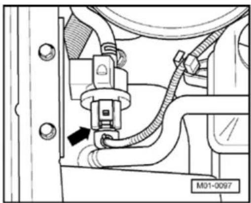
natural_image
Technical diagram of a mechanical assembly with hoses and connectors (no readable text or symbols)If the solenoid valve does not click:

- Disconnect 2-pin connector from Evaporative Emission (EVAP) Canister Purge Regulator Valve - N80- (arrow).

natural_image
Diagram of a connector with a light bulb and screwdriver, labeled M26-0009 (no text or symbols on the diagram itself)
- Connect LED test light VAG 1527 to disconnected connector using adapter cables from VAG 1594. LED must flash (bright/darker)
LED flashes:
- Press -C- button to abort output Diagnosis Test Mode (DTM).
01-108
Output Diagnosis Test Mode was aborted
Indicated on display:
- Switch off ignition.
- Replace Evaporative Emission (EVAP) Canister Purge RegulatorValve -N80-.
- Check DTC memory, repair Diagnostic Trouble Codes (DTCs) if necessary and then erase DTC memory Page 01-23, DTC memory, checking and erasing.
- Read readiness code Page 01-146. If the DTC memory has been erased or the Motronic Engine Control Module (ECM) - J220- was disconnected from battery (B+) positive, the readiness code must be generated again Page 01-149.
LED does not flash:
- Press -C- button to abort output Diagnosis Test Mode (DTM).
Output Diagnosis Test Mode was aborted
Indicated on display:
- Switch off ignition.
- Remove wiper arms and cowl panel:
⇒ Repair Manual, Electrical
Equipment; Repair Group 92
01-109


- Connect test box VAG 1598/31 to control module wiring harness. Engine Control Module (ECM) - J220- remains disconnected.
- Check wire for open circuit between test box socket 64 and 2-pin connector terminal 2 referring to Electrical Wiring Diagrams.
Wire resistance: max. 1.5 Ω
- Additionally check wire for short to battery positive and Ground (GND).
Specification:
- Check wire for open circuit between 2-pin connector terminal 1 and Fuel Pump (FP) relay -J17-referring to Electrical Wiring Diagrams.
Wire resistance: max. 1.5 Ω
If no wiring malfunction is found:
- Replace Motronic Engine Control Module (ECM) -J220- Page 24-173.
01-110
- Check DTC memory, repair Diagnostic Trouble Codes (DTCs) if necessary and then erase DTC memory Page 01-23DTC memory, checking and erasing.
- Erase learned values and adapt Motronic Engine Control Module (ECM) -J220- again Page 24-182.
- Read readiness code Page 01-146. If the DTC memory has been erased or the Motronic Engine Control Module (ECM) -J220- was disconnected from battery (B+) positive, the readiness code must be generated again Page 01-149.
2. Activating Secondary Air Injection (AIR) Solenoid Valve -N112-:
- Press → button.
Output Diagnosis Test Mode (DTM) → Secondary Air Injection Solenoid Valve

Indicated on display:
The Secondary Air Injection (AIR) Solenoid Valve must click, until the next final control element is activated by pressing → button.
01-111
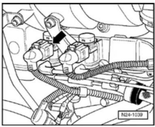
natural_image
Technical line drawing of an automotive engine assembly with hoses and components (no text or symbols)
natural_image
Diagram of an electrical connector with a bulb and pin, no text or symbols presentIf the valve does not click:

- Disconnect 2-pin connector from Secondary Air Injection (AIR) Solenoid Valve (arrow).

- Connect LED test light VAG 1527 to disconnected connector using adapter cables from VAG 1594. LED must flash (bright/darker)
LED flashes:
- Press -C- button to abort output Diagnosis Test Mode (DTM).
01-112
Output Diagnosis Test Mode was aborted
Indicated on display:
- Switch off ignition.
- Replace Secondary Air Injection (AIR) Solenoid Valve -N112-:
⇒ Repair Manual, 2.8 Liter VR6 4V Engine Mechanical, Engine Code(s): BDF; Repair Group 26
- Check DTC memory, repair Diagnostic Trouble Codes (DTCs) if necessary and then erase DTC memory Page 01-23, DTC memory, checking and erasing.
- Read readiness code Page 01-146. If the DTC memory has been erased or the Motronic Engine Control Module (ECM) - J220- was disconnected from battery (B+) positive, the readiness code must be generated again Page 01-149.
LED does not flash:
- Press -C- button to abort output Diagnosis Test Mode (DTM).
Output Diagnosis Test Mode was aborted
< Indicated on display:
- Switch off ignition.
- Remove wiper arms and cowl panel:
⇒ Repair Manual, Electrical
Equipment; Repair Group 92
01-113

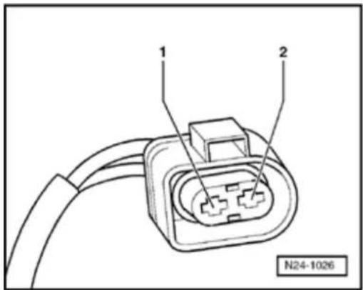
- Connect VAG 1598/31 test box to control module wiring harness. Engine Control Module (ECM) - J220- remains disconnected.
- Check wire for open circuit between test box socket 44 and 2-pin connector terminal 2 referring to Electrical Wiring Diagrams.
Wire resistance: max. 1.5 Ω
- Additionally check wire for short to battery positive and Ground (GND).
Specification:
- Check wire for open circuit between 2-pin connector terminal 1 and Fuel Pump (FP) relay -J17-referring to Electrical Wiring Diagrams.
Wire resistance: max. 1.5 Ω
If no wiring malfunction is found:
- Replace Motronic Engine Control Module (ECM) -J220- Page 24-173.
01-114
- Check DTC memory, repair Diagnostic Trou Codes (DTCs) if necessary and then erase I memory Page 01-23DTC memory, check and erasing.
- Erase learned values and adapt Motronic Engine Control Module (ECM) -J220- again Page 24-182.
- Read readiness code Page 01-146 If the DTC memory has been erased or the Motro Engine Control Module (ECM) -J220- was disconnected from battery (B+) positive, the readiness code must be generated again Page 01-149.
3. Activating Secondary Air Injection (AIR) Pump Relay -J299-:
- Press → -button.
Output Diagnosis Test Mode (DTM)
Secondary Air Injection (AIR) Pump Relay -J299-

Indicated on display:
The Secondary Air Injection (AIR) Pump Re J299- activates the Secondary Air Injection (Pump Motor -V101-, and this must run at intervals until the next control element is activated by pressing the → button.
If the Secondary Air Injection (AIR) Pump Motor V101- does not run at intervals:
- Remove center insulation tray:
⇒ Repair Manual, Body Exterior; Repair Group
01-115
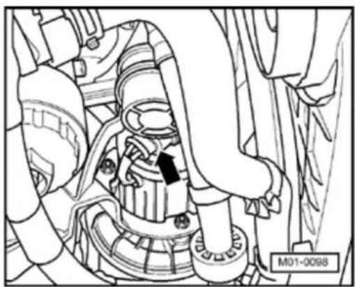
natural_image
Technical line drawing of a mechanical assembly with no visible text or symbols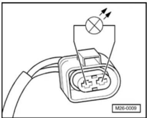
natural_image
Diagram of an electrical connector with a bulb and screwdriver, no text or symbols present- Disconnect 2-pin connector from Secondary Air Injection (AIR) Pump Motor (arrow).
- Connect LED test light VAG 1527 to disconnected connector using adapter cables from VAG 1594. LED must flash
01-116
LED flashes:
- Press -C- button to abort output Diagnosis Test Mode (DTM).
Output Diagnosis Test Mode was aborted

Indicated on display:
- Switch off ignition.
- Replace Secondary Air Injection (AIR) Pump Motor -V101-:
⇒ Repair Manual, 2.8 Liter VR6 4V Engine Mechanical, Engine Code(s): BDF; Repair Group 26 - Check DTC memory, repair Diagnostic Trouble Codes (DTCs) if necessary and then erase DTC memory Page 01-23DTC memory, checking and erasing.
- Read readiness code Page 01-146. If the DTC memory has been erased or the Motronic Engine Control Module (ECM) -J220- was disconnected from battery (B+) positive, the readiness code must be generated again Page 01-149.
If the LED does not flash but the Secondary Air Injection (AIR) Pump Relay clicks:
- Press -C- button to abort Output Diagnosis Test Mode (DTM).
Output Diagnosis Test Mode was aborted

Indicated on display:
- Switch off ignition.
01-117
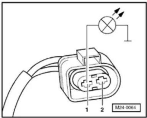
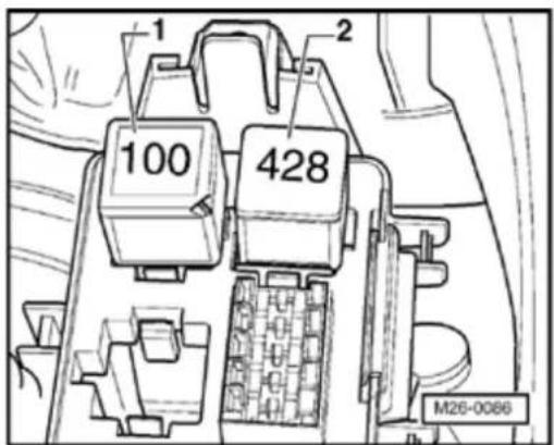

- Check wire for open circuit between Secondary Air Injection (AIR) pump motor -V101- terminal 1 and body Ground (GND).
Wire resistance: max. 1.5 Ω
If no electrical or wiring concerns are found:

- Pull Secondary Air Injection (AIR) Pump Relay -1- out of relay carrier in protective housing for control modules.
Note:
If tools are necessary to pull relays or control modules out of the relay plate, first disconnect battery Ground (GND) strap.
Before disconnecting battery Ground (GND) strap obtain code for radios with anti-theft coding.
01-118
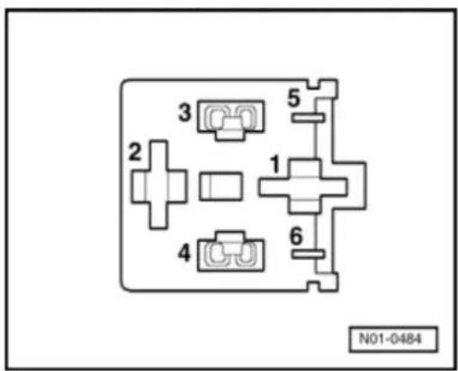
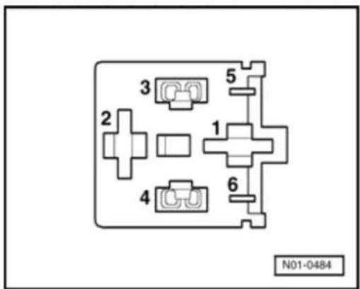

- Check wiring for open circuit between connector terminal 2 on Secondary Air Injection (AIR) Pump Motor and terminal 2 on relay plate.
- Wire resistance: max. 1.5 Ω
If no electrical or wiring concerns are found:

- Check wire for open circuit between terminal 1 of relay plate and fuel pump (FP) relay -J17-referring to Electrical Wiring Diagrams.
Wire resistance: max. 1.5 Ω
If no electrical or wiring concerns are found:
- Replace Secondary Air Injection (AIR) pump relay -J299-.
- Check DTC memory, repair Diagnostic Trouble Codes (DTCs) if necessary and then erase DTC memory Page 01-23, DTC memory, checking and erasing.
01-119
- Read readiness code Page 01-146f DTC memory has been erased or the Mo Engine Control Module (ECM) -J220- wa disconnected from battery (B+) positive, t readiness code must be generated again Page 01-149.
If the LED does not flash and the Second Air Injection (AIR) Pump Relay does not click:
- Press -C- button to abort output Diagnosi Mode (DTM).
Output Diagnosis Test Mode was aborted
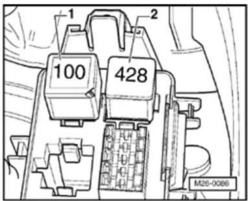
Indicated on display:
- Switch off ignition.
- Pull Secondary Air Injection (AIR) Pump 1- out of relay carrier in protective housin control modules.
Note:
If tools are necessary to pull relays or cc modules out of the relay plate, first disc battery Ground (GND) strap.
Before disconnecting battery Ground (G strap obtain code for radios with anti-the coding.
01-120
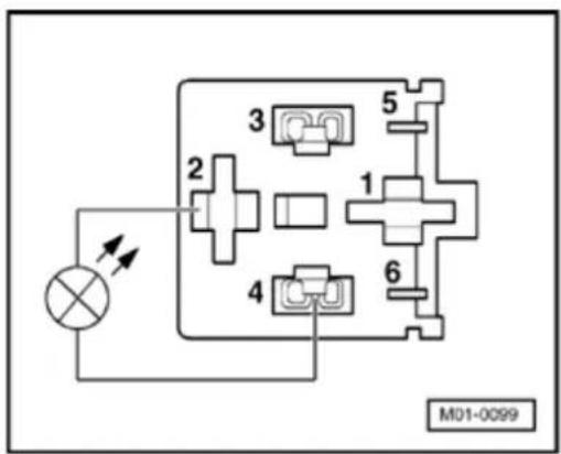
flowchart
graph TD
    A["Power Source"] --> B["Component 2"]
    B --> C["Component 3"]
    C --> D["Component 4"]
    D --> E["Component 5"]
    E --> F["Component 6"]
    F --> G["Motor M01-0099"]
Output Diagnosis Test Mode was aborted

- Connect LED test light VAG 1527 to terminals 2 and 4 on relay plate using adapter cables from VAG 1594.
- Initiate output Diagnosis Test Mode (DTM) again and activate Secondary Air Injection (AIR) pump relay -J299-.
LED must flash.
Note:
Run engine briefly first if there is a requirement to repeat Output Diagnosis Test Mode (DTM).
LED flashes:
- Press -C- button to abort output Diagnosis Test Mode (DTM).

Indicated on display:
- Switch off ignition.
- Replace Secondary Air Injection (AIR) pump relay -J299-.
- Check DTC memory, repair Diagnostic Trouble Codes (DTCs) if necessary and then erase DTC memory Page 01-23, DTC memory, checking and erasing.
01-121
- Read readiness code Page 01-146f DTC memory has been erased or the Mo Engine Control Module (ECM) -J220- wa disconnected from battery (B+) positive, t readiness code must be generated again Page 01-149.
LED does not flash:
- Press -C- button to abort output Diagnosi Mode (DTM).
Output Diagnosis Test Mode was aborted
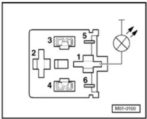
Indicated on display:
- Switch off ignition.
- Connect LED test light VAG 1527 to term of relay plate and body Ground (GND) us adapter cables from VAG 1594.
LED must light up
01-122
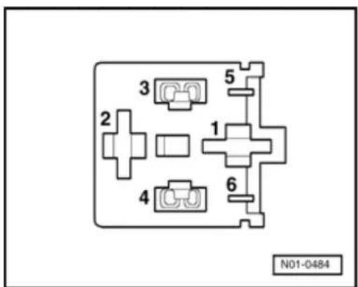
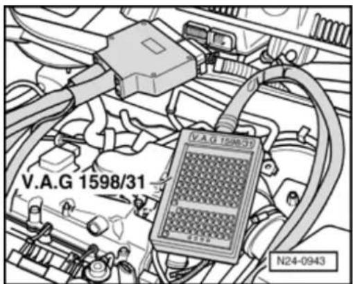
LED does not light-up:

- Check wire for open circuit between terminal 1 of relay plate and fuel pump relay -J17-referring to Electrical Wiring Diagrams.
Wire resistance: max. 1.5 Ω
LED lights up:
- Remove wiper arms and cowl panel:
⇒ Repair Manual, Electrical Equipment; Repair Group 92

- Connect test box VAG 1598/31 to control module wiring harness. Engine Control Module (ECM) - J220- remains disconnected.
01-123


- Check wire for open circuit between test box socket 46 and terminal 4 on relay plate referring to Electrical Wiring Diagrams.
Wire resistance: max. 1.5 Ω
If no electrical or wiring concerns are found:
- Replace Motronic Engine Control Module (ECM) -J220- Page 24-173.
- Check DTC memory, repair Diagnostic Trouble Codes (DTCs) if necessary and then erase DTC memory Page 01-23, DTC memory, checking and erasing.
- Erase learned values and adapt Motronic Engine Control Module (ECM) -J220- again Page 24-182.
- Read readiness code Page 01-146. If the DTC memory has been erased or the Motronic Engine Control Module (ECM) - J220- was disconnected from battery (B+) positive, the readiness code must be generated again Page 01-149.
01-124
4. Activating Intake Manifold Change-Over Valve -N156-:
- Press → button.
Output Diagnosis Test Mode → Intake Manifold Change-Over Valve -N156-
Indicated on display:
The Intake Manifold Change-Over Valve must click until the next final control element is activated by pressing → button.
Note:
If there is sufficient vacuum the Intake Manifold Change-Over Valve -N156- activates the intake manifold change-over valve actuator. The change-over valve is located below the intake manifold, on right next to the Secondary Air Injection (AIR) Solenoid Valve. Checking variable intake manifold change-over Page 24-117.
If the valve does not click:
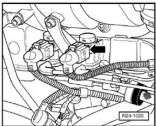
natural_image
Technical diagram of an automotive engine assembly showing hoses and components (no readable text or symbols)- Disconnect 2-pin connector from Intake Manifold Change-Over Valve -N156- (arrow).
01-125
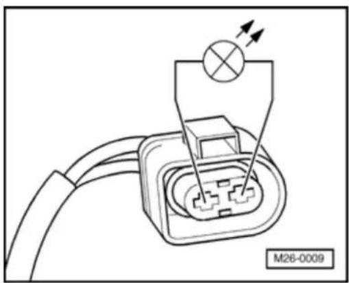
natural_image
Diagram of an electrical connector with a bulb and indicator lights, no text or symbols presentOutput Diagnosis Test Mode was aborted
- Connect LED test light VAG 1527 to detached connector using adapter cables from VAG 1594. LED must flash (bright/darker)
LED flashes:
- Press -C- button to abort output Diagnosis Test Mode (DTM).
< Indicated on display:
- Switch off ignition.
- Replace Intake Manifold Change-Over Valve -N156- Page 24-12, item 2.
- Check DTC memory, repair Diagnostic Trouble Codes (DTCs) if necessary and then erase DTC memory Page 01-23, DTC memory, checking and erasing.
- Read readiness code Page 01-146. If the DTC memory has been erased or the Motronic Engine Control Module (ECM) - J220- was disconnected from battery (B+) positive, the readiness code must be generated again Page 01-149.
01-126
LED does not flash:
- Press -C- button to abort output Diagnosi Mode (DTM).
Output Diagnosis Test Mode was aborted
Indicated on display:
- Switch off ignition.
- Remove wiper arms and cowl panel:
⇒ Repair Manual, Electrical Equipment; Re Group 92

- Connect test box VAG 1598/31 to control module wiring harness. Engine Control M (ECM) -J220- remains disconnected.
01-127


- Check wire for open circuit between test box socket 121 and 2-pin connector terminal 2 referring to Electrical Wiring Diagrams.
Wire resistance: max. 1.5 Ω
- Additionally check wire for short to battery positive and Ground (GND).
Specification:
- Check wire for open circuit between 2-pin connector terminal 1 and Motronic Engine Control Module (ECM) power supply relay -J271- referring to Electrical Wiring Diagrams.
Wire resistance: max. 1.5 Ω
If no electrical or wiring concerns are found:
- Replace Motronic Engine Control Module (ECM) -J220- Page 24-173.
- Check DTC memory, repair Diagnostic Trouble Codes (DTCs) if necessary and then erase DTC memory Page 01-23, DTC memory, checking and erasing.
- Erase learned values and adapt Motronic Engine Control Module (ECM) -J220- again Page 24-182.
- Read readiness code Page 01-146. If the DTC memory has been erased or the Motronic Engine Control Module (ECM) - J220- was disconnected from battery (B+) positive, the readiness code must be generated again Page 01-149.
01-128
Output Diagnosis Test Mode → Valve -1- for camshaft adjustment -N205-
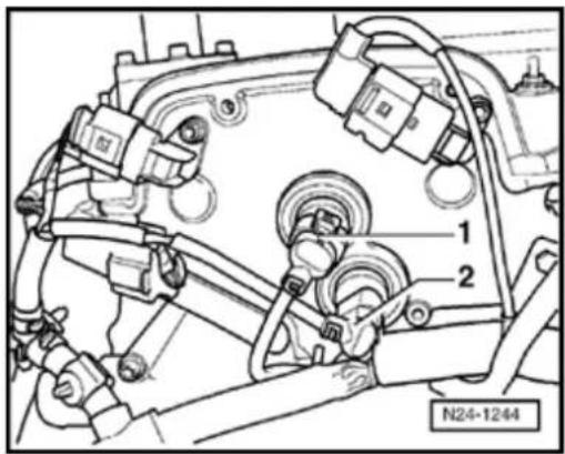
5. Activating Valve -1- for camshaft adjustment -N205-:
- Press → -button.
Indicated on display:
The Valve -1- for camshaft adjustment must click until the next final control element is activated by pressing → button.
Note:
The Valve -1- for camshaft adjustment -N205- is barely audible when operating.
If the valve does not click:
- Disconnect 2-pin connector from Valve -1- for camshaft adjustment -N205- -1-.
Note:
Mark connector and component before pulling connector off.
01-129

natural_image
Diagram of an electrical connector with a bulb and pin, no text or symbols presentOutput Diagnosis Test Mode was aborted
- Connect LED test light VAG 1527 to disconnected connector using adapter cables from VAG 1594. LED must flash (bright/darker)
LED flashes:
- Press -C- button to abort output Diagnosis Test Mode (DTM).
Indicated on display:
- Switch off ignition. - Replace control housing: ⇒ Repair Manual, 2.8 Liter VR6 4V Engine Mechanical, Engine Code(s): BDF, Repair Group 15; Valve train, servicing
Note:
The control housing is only replaced complete with Valve -1- for camshaft adjustment -N205- and Camshaft Adjustment Valve 1 (exhaust) -N318-
- Check DTC memory, repair Diagnostic Trouble Codes (DTCs) if necessary and then erase DTC memory Page 01-23, DTC memory, checking and erasing.
01-130
- Read readiness code Page 01-146f DTC memory has been erased or the Mo Engine Control Module (ECM) -J220- wa disconnected from battery (B+) positive, t readiness code must be generated again Page 01-149.
LED does not flash:
- Press -C- button to abort output Diagnosi Mode (DTM).
Output Diagnosis Test Mode was aborted
Indicated on display:
- Switch off ignition.
- Remove wiper arms and cowl panel:
⇒ Repair Manual, Electrical Equipment; Re Group 92

- Connect test box VAG 1598/31 to control module wiring harness. Engine Control M (ECM) -J220- remains disconnected.
01-131
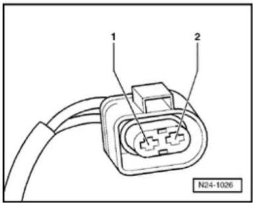

- Check wire for open circuit between test box socket 115 and 2-pin connector terminal 2 referring to Electrical Wiring Diagrams.
Wire resistance: max. 1.5 Ω
- Additionally check wire for short to battery positive and Ground (GND).
Specification:
- Check wire for open circuit between 2-pin connector terminal 1 and Motronic Engine Control Module (ECM) Power Supply Relay -J271- referring to Electrical Wiring Diagrams.
Wire resistance: max. 1.5 Ω
If no electrical or wiring concerns are found:
- Replace Motronic Engine Control Module (ECM) -J220- Page 24-173.
- Check DTC memory, repair Diagnostic Trouble Codes (DTCs) if necessary and then erase DTC memory Page 01-23, DTC memory, checking and erasing.
- Erase learned values and adapt Motronic Engine Control Module (ECM) -J220- again Page 24-182.
- Read readiness code Page 01-146. If the DTC memory has been erased or the Motronic Engine Control Module (ECM) - J220- was disconnected from battery (B+) positive, the readiness code must be generated again Page 01-149.
01-132
Output Diagnosis Test Mode Leak Detection Pump tank ventilation system

natural_image
Technical line drawing of a mechanical assembly with hoses and a valve (no text or symbols)6. Activating Leak detection pump (LDP) -V144-:
- Press → b utton.
Indicated on display:
The LDP must click, at intervals, until the next final control element is activated by pressing → button.
If the Leak Detection Pump (LDP) - V144- does not run at intervals:
- Remove rear right wheel housing liner: ⇒ Repair Manual, Body Exterior; Repair Group 66; Exterior equipment, Wheel housing liner
- Disconnect 3-pin connector from Leak Detection Pump (LDP) - V144- (arrow).
01-133
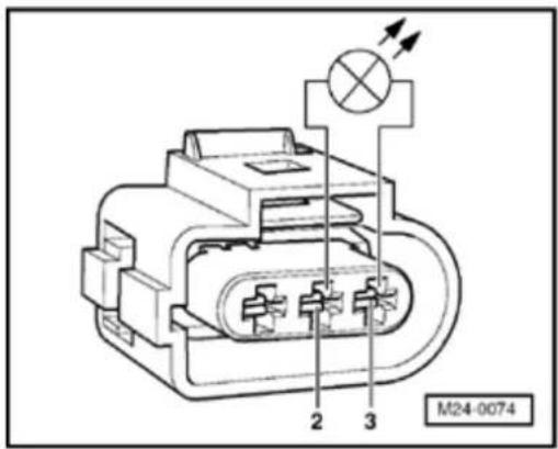
Output Diagnosis Test Mode was aborted
- Connect LED test light VAG 1527 terminals 2 and 3 of detached connector using adapter cables from VAG 1594. LED must flash (bright/darker)
LED flashes:
- Press -C- button to abort output Diagnosis Test Mode (DTM).
< Indicated on display:
- Switch off ignition.
- Replace Leak Detection Pump (LDP) -V144-:
⇒ Repair Manual, 2.8 Liter VR6 4V Engine Mechanical, Engine Code(s): BDF; Repair Group 20 - Check DTC memory, repair Diagnostic Trouble Codes (DTCs) if necessary and then erase DTC memory Page 01-23, DTC memory, checking and erasing.
- Read readiness code Page 01-146. If the DTC memory has been erased or the Motronic Engine Control Module (ECM) - J220- was disconnected from battery (B+) positive, the readiness code must be generated again Page 01-149.
01-134
LED does not flash:
- Press -C- button to abort output Diagnosi Mode (DTM).
Output Diagnosis Test Mode was aborted
Indicated on display:
- Switch off ignition.
- Remove wiper arms and cowl panel:
⇒ Repair Manual, Electrical Equipment; Re Group 92
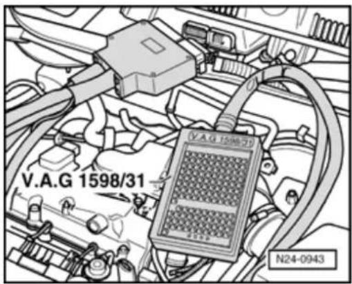
- Connect test box VAG 1598/31 to control module wiring harness. Engine Control M (ECM) -J220- remains disconnected.
01-135
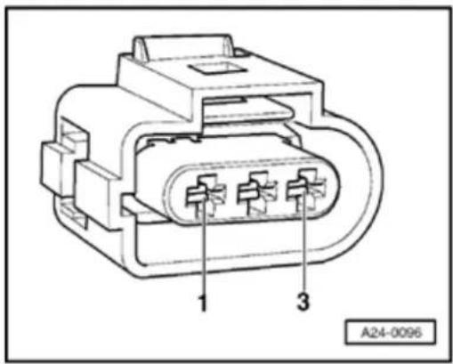

- Check wiring for open circuit between test box and 3-pin connector referring to Electrical Wiring Diagrams
Terminal 1 and socket 80
Terminal 2 and socket 25
Wire resistance: max. 1.5 Ω
- Additionally check wire for short to battery positive and Ground (GND). Specification:
- Check wire for open circuit between 3-pin connector terminal 3 and fuel pump relay -J17-referring to Electrical Wiring Diagrams.
Wire resistance: max. 1.5 Ω
If no electrical or wiring concerns are found:
- Replace Motronic Engine Control Module (ECM) -J220- Page 24-173.
- Check DTC memory, repair Diagnostic Trouble Codes (DTCs) if necessary and then erase DTC memory Page 01-23, DTC memory, checking and erasing.
- Erase learned values and adapt Motronic Engine Control Module (ECM) -J220- again Page 24-182.
01-136
- Read readiness code Page 01-146. If the DTC memory has been erased or the Motronic Engine Control Module (ECM) -J220- was disconnected from battery (B+) positive, the readiness code must be generated again Page 01-149.
7. Activating Camshaft Adjustment Valve 1 (exhaust) -N318-:
- Press → button.
Output Diagnosis Test Mode 17457 / Literature

Indicated on display of VAG 1551 scan tool or VAG 1552:
or
Output Diagnosis Test Mode Camshaft Adjustment Valve

Indicated on display of VAS 5051
- Press → button.
The Camshaft Adjustment Valve 1 (exhaust) must click until the next Output Diagnostic Test element is activated by pressing → button.
Note:
The Camshaft Adjustment Valve 1 (exhaust) is barely audible when operating.
01-137


natural_image
Diagram of an electrical connector with a bulb and screwdriver, no text or symbols presentIf the valve does not click:

- Disconnect 2-pin connector from Camshaft Adjustment Valve 1 (exhaust) -N318- -2-.
Note:
Mark connector and component before pulling connector off.

- Connect LED test light VAG 1527 to disconnected connector using adapter cables from VAG 1594. LED must flash (bright/darker)
LED flashes:
- Press -C- button to abort output Diagnosis Test Mode (DTM).
01-138
Output Diagnosis Test Mode was aborted
Indicated on display:
- Switch off ignition.
- Replace engine control housing:
⇒ Repair Manual, 2.8 Liter VR6 4V Engine Mechanical, Engine Code(s): BDF; Repair Group 15, Valve train, servicing
Note:
The control housing is only replaced complete with Valve -1- for camshaft adjustment -N205- and Camshaft Adjustment Valve 1 (exhaust) -N318-
- Check DTC memory, repair Diagnostic Trouble Codes (DTCs) if necessary and then erase DTC memory Page 01-23, DTC memory, checking and erasing.
- Read readiness code Page 01-146. If the DTC memory has been erased or the Motronic Engine Control Module (ECM) - J220- was disconnected from battery (B+) positive, the readiness code must be generated again Page 01-149.
LED does not flash:
- Press -C- button to abort output Diagnosis Test Mode (DTM).
Output Diagnosis Test Mode was aborted
Indicated on display:
- Switch off ignition.
- Remove wiper arms and cowl panel:
⇒ Repair Manual, Electrical Equipment, Repair Group 92
01-139


- Connect test box VAG 1598/31 to control module wiring harness. Engine Control Module (ECM) - J220- remains disconnected.
- Check wire for open circuit between test box socket 120 and 2-pin connector terminal 2 referring to Electrical Wiring Diagrams.
Wire resistance: max. 1.5 Ω
- Additionally check wire for short to battery positive and Ground (GND).
Specification:
- Check wire for open circuit between 2-pin connector terminal 1 and Motronic Engine Control Module (ECM) Power Supply Relay -J271- referring to Electrical Wiring Diagrams.
Wire resistance: max. 1.5 Ω
If no electrical or wiring concerns are found:
01-140
- Replace Motronic Engine Control Module (ECM) -J220- Page 24-173.
- Check DTC memory, repair Diagnostic Trouble Codes (DTCs) if necessary and then erase DTC memory Page 01-23DTC memory, checking and erasing.
- Erase learned values and adapt (match) Motronic Engine Control Module (ECM) -J220-again Page 24-182.
- Read readiness code Page 01-146. If the DTC memory has been erased or the Motronic Engine Control Module (ECM) -J220- was disconnected from battery (B+) positive, the readiness code must be generated again Page 01-149.
8. Activating Brake System Vacuum Pump - V192- (only vehicles with an automatic transmission):
- Press → button.
Output Diagnosis Test Mode
17836 / Literature
Output Diagnosis Test Mode
Brake System Vacuum Pump activation

Indicated on display of VAG 1551 scan tool or VAG 1552:
or
Indicated on display of VAS 5051:
The Brake Booster Control Module -J542-activates the Brake System Vacuum Pump -V192-, and this must run until the next control element is activated by pressing the → button.
01-141
If the Brake System Vacuum Pump -V192- does not run:
- Press -C- button to abort output Diagnosis Test Mode (DTM).
Output Diagnosis Test Mode was aborted
Indicated on display:
- Switch off ignition.
- Check Brake System Vacuum Pump -V192-:
⇒ Repair Manual, Brake System; Repair Group 47
- Check DTC memory, repair Diagnostic Trouble Codes (DTCs) if necessary and then erase DTC memory Page 01-23DTC memory, checking and erasing.
- Read readiness code Page 01-146. If the DTC memory has been erased or the Motronic Engine Control Module (ECM) -J220- was disconnected from battery (B+) positive, the readiness code must be generated again Page 01-149.
01-142
9...14. Activating fuel injectors (-N30-... -N33-, -N83- and -N84-):
- Press → button.
Output Diagnosis Test Mode
Cylinder 1 Fuel Injector -N30-
Indicated on display:
- Press → b button again so that fuel injector is actuated five times.
Cylinder 1 Fuel Injector -N30-clicks five times.
Note:
The fuel pump must run and the sound of fuel flowing through the fuel pressure control must be heard clearly.
If the fuel pump does not run:
- Check fuel pump function and voltage supply:
⇒ Repair Manual, 2.8 Liter VR6 4V Engine Mechanical, Engine Code(s): BDF; Repair Group 20
Fuel pump runs:
- To activate fuel injectors for cyl. 2 to 6, use procedure, as for fuel injector 1, to activate each subsequent fuel injector.
Using this procedure, each fuel injector can be checked one after the other according to firing order.
01-143
If one of the fuel injectors is not activated (does not click):
- Press -C- button to abort output Diagnosis Test Mode (DTM).
Output Diagnosis Test Mode was aborted

Indicated on display:
- Switch off ignition.
- Check injectors Page 24-97
- Check DTC memory, repair Diagnostic Trouble Codes (DTCs) if necessary and then erase DTC memory Page 01-23DTC memory, checking and erasing.
- Read readiness code Page 01-146. If the DTC memory has been erased or the Motronic Engine Control Module (ECM) -J220- was disconnected from battery (B+) positive, the readiness code must be generated again Page 01-149.
If all fuel injectors have been activated (clicks):
- Press → button.
Output Diagnosis Test Mode


Indicated on display:
END
01-144
- Press buttons -0- and -6- for function "End output" and confirm entry with -Q- button.
- Switch off ignition.
Readiness code
Function
The readiness code is an 8-digit number code which displays the status of the emission relevant diagnosis.
When the diagnosis for a system (e.g. secondary air system) has been successfully completed, the corresponding position in the number code will change from 1 to 0.
The diagnosis is performed at regular intervals during normal driving. It is recommended that the readiness code be generated after performing repairs on an emission relevant system, to guarantee that these systems function correctly. If a malfunction is detected during the diagnosis it will be stored in the DTC memory.
Each time the DTC memory is erased or the voltage supply is interrupted the readiness code will be erased.
01-146

Read readiness code
Special tools, workshop equipment, testers, measuring instruments and auxiliary items required

◆ VAG 1551 Scan tool (or VAG 1552 vehicle system tester) with VAG 1551/3 adapter cable
Note:
All functions which could previously be performed with VAG 1551/1552 can also be performed with the vehicle diagnostic, testing and information system VAS 5051.
Work sequence
- Connect VAG 1551 scan tool ((VAG 1552) and select Engine Control Module (ECM) with the "Address word" 01. Engine must be running at idle: (Connecting scan tool and selecting Engine Control Module (ECM) Page 01-12).
Rapid data transfer
HELP
Select function XX

Indicated on display:
- Press buttons -1- and -5- for function "Readiness code" and confirm entry with -Q- button.
01-147
Readiness code
00000000 - Test complete

Readiness code
00101101 - Test not complete
Must appear on display when all diagnosis functions have been successfully completed:
< Indicated on display:
- Press → button.
- Press buttons -0- and -6- for function "End output" and confirm entry with -Q- button.
- Switch off ignition.
Appears on display:
One of the diagnostic checks has not run through successfully:
- Press → b utton.
- G enerate readiness code Page 01-149.
01-148
Significance of figures in 8 digit number block, display zone 1 - Readiness code
| The readiness code is generated only when all display zones show 0 | ||||||||
| 1 | 2 | 3 | 4 | 5 | 6 | 7 | 8 | Diagnostic function |
| 0 | Three Way Catalytic Converter (TWC) | |||||||
| 0 | Three Way Catalytic Converter (TWC) heating (currently no diagnosis/always "0") | |||||||
| 0 | Evaporative Emissions (EVAP) Canister system (Tank ventilation system) | |||||||
| 0 | Secondary air system | |||||||
| 0 | Air conditioner (currently no diagnosis/always "0") | |||||||
| 0 | Oxygen Sensor (O2S)s | |||||||
| 0 | Oxygen Sensor (O2S) heating | |||||||
| 0 | Exhaust gas recirculation (not installed/always "0") | |||||||
01-149


Generating readiness code
Special tools, workshop equipment, testers, measuring instruments and auxiliary items required

◆ VAG 1551 scan tool (or VAG 1552) with VAG 1551/3 Adapter cable
Note:
All functions which could previously be performed with VAG 1551/1552 can also be performed with the vehicle diagnostic, testing and information system VAS 5051.
Test prerequisites

- All fuses must be OK.
01-150

natural_image
Technical line drawing of an electrical connector with multiple ports and wiring (no text or symbols)
• The main fuses must be OK.
- The battery voltage must be at least 11.5 V.
- If the vehicle is equipped with air conditioning, this must be switched off.
- Selector lever must be in position "P" or "N" on vehicles with an automatic transmission.
- Exhaust system between Three Way Catalytic Converter (TWC) and cylinder head must be free of leaks
- Ignition switched on, engine not running.
- Fuel Pump (FP) relay -J17- must be OK., checking:
⇒ Electrical Wiring Diagrams, Troubleshooting & Component Locations
- The signal from Brake Light Switch -F- and Brake Vacuum Vent Valve Switch -F47- -F85- must be OK., checking Page 24-206.
- Engine Coolant Temperature (ECT) must be 85...110 °C ⇒display group 4, display zone 3.
- Intake Air Temperature (IAT) less than 80^ C display group 4, display zone 4.
- Three Way Catalytic Converter (TWC) temperature must be at least 380 °C ⇒d isplay group 34, display zone 2.
01-151
Work sequence
- Connect VAG 1551 scan tool (or VAG 1552). Then switch ignition on and select Motronic Engine Control Module (ECM) -J220- with the "Address word" 01. (Connecting scan tool and selecting Engine Control Module (ECM) Pa 01-12).
Work step 1: Check DTC memory
Rapid data transfer
HELP
Select function XX
Indicated on display:
- Operate scan tool taking into account the information on the display:
- Press buttons -0- and -2- for function "Check DTC memory" and confirm entry with Q button
X Diagnostic Trouble Codes (DTCs) detected!
The number of Diagnostic Trouble Codes (DTCs stored or "No DTC detected!" will be shown on the display.
If a DTC is stored:
01-152
Repair Diagnostic Trouble Codes (DTCs) printed out using DTC table:
♦ SAE P0 codes ⇒ Page 01-30,
♦ SAE P1 codes ⇒ Page 01-58,
♦ SAE P2 codes ⇒ Page 01-98,
♦ SAE P3 codes ⇒ Page 01-99.
If no DTC is stored:
- Press → b utton.
- Continue with work step 3
Work step 2: Erase DTC memory
Rapid data transfer HELP Select function XX
< Indicated on display:
- Press buttons -0- and -5- for function "Erase DTC memory" and confirm entry with -Q- button.
Note:
The readiness code is reset or erased each time DTC memory is erased.
Rapid data transfer → DTC memory is erased!
Indicated on display:
01-153
Note:
If the ignition is switched off between "Check DTC memory" and "Erase DTC memory" the DTC memory will not be erased.
- Press → b utton.
Work step 3: Adjust the Throttle Valve Control Module -J338- to the Motronic Engine Control Module (ECM) -J220-
Rapid data transfer HELP
Select function XX
Basic setting
Input display group number XXX
System in basic setting 60 →
xxx.x % xxx.x % x ADP. runs
System in basic setting 60 →
< Indicated on display:
- Press buttons -0- and -4- for function "Initiate basic setting" and confirm entry with -Q- button.
< Indicated on display:
- Press buttons -0-, -6- and -0- for "Display group number 60" and confirm entry with -Q- button.
Indicated on display: (1 to 4 = display zones)
- Check specifications in display zones 3 and 4:
Display zone 3: 0 to 8
Display zone 4: ADP. runs, ADP. OK.
Indicated on display: (1 to 4 = display zones)
01-154
- Terminate engine basic setting at earliest after 30 seconds by pressing → button.
If the display does not indicate as described:
- Check Throttle Valve Control Module -J338- Page 24-59.
If the display indicates as described:
- Start engine and run at idle.
Note:
Engine must not be switched again off during work sequence.
Work step 4: Requesting temperature
Rapid data transfer
HELP
Select function XX

Indicated on display:
- Press buttons -0- and -8- for function "Read measured value (data) block" and confirm entry with Q button.
Read measured value block
Input display group number XXX

Indicated on display:
- Press buttons -0-, -0- and -4- for "Display group number 4" and confirm entry with -Q- button.
Read measured value block 4

1 2 3 4

Indicated on display: (1 to 4 = display zones)
01-155
- Read Engine Coolant Temperature value in display zone 3.
Specification: 85 to 110 °C
- Read Intake Air Temperature value in display zone 4.
Specification: Ambient temperature less than 80 °C
If the specifications are obtained:
- Press → b utton.
Work step 5: Evaporative Emissions (EVAP) Canister system diagnosis (Tank ventilation system)
Rapid data transfer
HELP

Select function XX
Indicated on display:
- Press buttons -0- and -4- for function "Initiate basic setting" and confirm entry with -Q- button.
Basic setting

Input display group number XXX
Indicated on display:
- Press buttons -0-, -7- and -1- for "Display group number 71" and confirm entry with -Q- button.
Note:
The engine must not be loaded during this diagnosis, if this occurs the diagnosis will be interrupted and will not start again until the engine is revved-up.
01-156
| System in basic setting 71 | → | ||
| 1 | 2 | 3 | 4 |
Indicated on display: (1 to 4 = display zones)
If "Reed op." appears in display zone 1:
- O pen fuel tank filler cap briefly to release pressure in fuel tank. This will close reed terminal.
If the diagnosis is initiated by the Motronic Engine Control Module (ECM) -J220- the display in display zone 4 jumps from "Test OFF" to "Test ON".
- L eave engine running at idle until specification "Sys. OK." is displayed in display zone 4.
Note:
If the display in display zone 4 jumps from "Test OFF" to "Test ON" during the diagnosis, repeat the diagnosis again. When repeating the diagnosis, the diagnosis can take up to 60 seconds before the display in display zone 4 jumps from "Test OFF" to "Test ON".
If "Sm leak or La leak" (meaning Small leak or Large leak) appears in display zone 2 and "Sys. n.OK." appears in display zone 4:
- Press → b utton.
01-157
- Check DTC memory, repair Diagnostic Trouble Codes (DTCs) if necessary and then erase DTC memory Page 01-23DTC memory, checking and erasing.
- Read readiness code Page 01-146. If the DTC memory has been erased or the Motronic Engine Control Module (ECM) -J220- was disconnected from battery (B+) positive, the readiness code must be generated again Page 01-149.
If no DTC is stored:
- Check Evaporative Emissions (EVAP) Canister system for leaks:
⇒ Repair Manual, 2.8 Liter VR6 4V Engine Mechanical, Engine Code(s): BDF; Repair Group 20
If "Sys. OK." appears in display zone 4:
- Press → b utton.
Work step 6: Oxygen Sensor (O2S) control diagnosis status before Three Way Catalytic Converter (TWC)
Rapid data transfer
HELP

Indicated on display:
Select function XX
- Press buttons -0- and -8- for function "Read measured value (data) block" and confirm entry with -Q- button.
Read measured value block

Indicated on display:
Input display group number XXX
01-158

- Press buttons -0-, -3- and -0- for "Display group number 30" and confirm entry with -Q- button.
Indicated on display: (1 to 2 = display zones)
- Check Oxygen Sensor (O2S) control status before Three Way Catalytic Converter (TWC) (display zone 1):
Specification: 111
Significance of figures in 3 digit number block Page 01-217.
Note:
The bits in display zones 1 will not be set to 1 until the Three Way Catalytic Converter (TWC) temperature rises above 380^ C ( display groups 34, display zone 2).
If the specification is not obtained:
- Press → b utton.
- Check Oxygen Sensor (O2S) heater of Oxygen Sensor (O2S) before Three Way Catalytic Converter (TWC) Page 24-38.
If the specification is obtained:
- Press → b utton.
01-159
| Rapid data transfer | HELP |
| Select function XX |
| Basic setting |
| Input display group number XXX |
| System in basic setting 34 | |||
| 1 | 2 | 3 | |
Work step 7: Oxygen Sensor (O2S) aging diagnosis of Oxygen Sensor (O2S) before Three Way Catalytic Converter (TWC)
Indicated on display:
- Press buttons -0- and -4- for function "Initiate basic setting" and confirm entry with -Q- button.
< Indicated on display:
- Press buttons -0-, -3- and -4- for "Display group number 34" and confirm entry with -Q- button.
Indicated on display: (1...4 = display zones)
- Depress brake pedal and hold.
- Depress accelerator down to wide open throttle position.
Engine speed will be increased by Motronic Engine Control Module (ECM) -J220- to approx. 2300 rpm. - Depress brake pedal and accelerator down until display in display zone 4 jumps from "Test OFF" to "Test ON". When performing this test Three Way Catalytic Converter (TWC) temperature in display zone 2 must be at least 380 °C.
01-160
Note:
This process can take approx. 90 seconds.
- Depress brake pedal and accelerator down until display zone 4 displays specification "B1-P1 OK.".
- Release brake and accelerator pedals.
If "B1 P1 n.OK." appears in display zone 4:
- Press → b utton.
- Check DTC memory, repair Diagnostic Trouble Codes (DTCs) if necessary and then erase DTC memory Page 01-23DTC memory, checking and erasing.
- Read readiness code Page 01-146. If the DTC memory has been erased or the Motronic Engine Control Module (ECM) -J220- was disconnected from battery (B+) positive, the readiness code must be generated again Page 01-149.
If no DTC is stored:
- Check aging of Oxygen Sensor (O2S) before Three Way Catalytic Converter (TWC) Page 24-150.
If "B1 P1 OK." appears in display zone 4:
- Press C button.
01-161
Basic setting
Input display group number XXX
System in basic setting 216
1 2 3 4
Work step 8: Fuel supply system diagnosis (part load)
< Indicated on display:
- Press buttons -2-, -1- and -6- for "Display group number 216" and confirm entry with -Q- button.
< Indicated on display: (1 to 4 = display zones)
- Depress brake pedal and hold.
- Depress accelerator down to wide open throttle position.
Engine speed will be increased by Motronic Engine Control Module (ECM) -J220- to approx. 2300 rpm.
- Depress brake pedal and accelerator down until display zone 4 displays (after approx. 75 seconds) specification "xxxxx100".
- Release brake and accelerator pedals.
If the display does not indicate as described:
- Press → b utton.
01-162
- Check DTC memory, repair Diagnostic Trouble Codes (DTCs) if necessary and then erase DTC memory Page 01-23DTC memory, checking and erasing.
- Read readiness code Page 01-146. If the DTC memory has been erased or the Motronic Engine Control Module (ECM) -J220- was disconnected from battery (B+) positive, the readiness code must be generated again Page 01-149.
If the display indicates as described:
- Press → b utton.
Work step 9: Oxygen Sensor (O2S) control diagnosis status after Three Way Catalytic Converter (TWC)
Rapid data transfer
HELP

Select function XX
Indicated on display:
- Press buttons -0- and -8- for function "Read measured value (data) block" and confirm entry with -Q- button.
Read measured value block

Input display group number XXX
Indicated on display:
- Press buttons -0-, -3- and -0- for "Display group number 30" and confirm entry with -Q- button.
Read measured value block 30

1
2
Indicated on display: (1...2 = display zones)
01-163
- Check Oxygen Sensor (O2S) control status after Three Way Catalytic Converter (TWC) (display zone 2): Specification: 111
Significance of figures in 3 digit number block Page 01-217.
Note:
The bits in display zone 2 will not be set to 1 until the Three Way Catalytic Converter (TWC) temperature rises above 380^ ( display groups 34, display zone 2).
If the specification is not obtained:
- Press → b utton.
- Check Oxygen Sensor (O2S) heater of Oxygen Sensor (O2S) after Three Way Catalytic Converter (TWC) Page 24-45.
If the specification is obtained:
- Press → b utton.
Work step 10: Oxygen Sensor (O2S) aging diagnosis of Oxygen Sensor (O2S) after Three Way Catalytic Converter (TWC)
Rapid data transfer
Select function XX
HELP

Indicated on display:
- Press buttons -0- and -4- for function "Initiate basic setting" and confirm entry with -Q- button.
01-164
Basic setting
Input display group number XXX
| System in basic setting 43 | → | ||
| 1 | 2 | 3 | 4 |
Indicated on display:
- Press buttons -0-, -4- and -3- for "Display group number 43" and confirm entry with -Q- button.
< Indicated on display: (1 to 4 = display zones)
- Depress brake pedal and hold.
- Depress accelerator down to wide open throttle position.
Engine speed will be increased by Motronic Engine Control Module (ECM) -J220- to approx. 2300 rpm.
- Depress and hold brake pedal and accelerator until display in display zone 4 jumps from "Test OFF" to "Test ON", when performing this test the Three Way Catalytic Converter (TWC) temperature in display zone 2 must be at least 380 °C.
Note:
This process can take approx. 30 seconds.
- Depress and hold brake pedal and accelerator until display zone 4 displays specification "B1 P2 OK.".
- Release brake and accelerator pedals.
01-165
If "B1 P2 n.OK." appears in display zone 4:
- Press → b utton.
- Check DTC memory, repair Diagnostic Trouble Codes (DTCs) if necessary and then erase DTC memory Page 01-23 DTC memory, checking and erasing.
- Read readiness code Page 01-146. If the DTC memory has been erased or the Motronic Engine Control Module (ECM) -J220- was disconnected from battery (B+) positive, the readiness code must be generated again Page 01-149.
If no DTC is stored:
- Check aging of Oxygen Sensor (O2S) after Three Way Catalytic Converter (TWC) Page 24-154.
If "B1 P2 OK." appears in display zone 4:
- Press -C- button.
Work step 11: Oxygen Sensor (O2S) diagnosis after Three Way Catalytic Converter (TWC) (operational readiness)
Basic setting
Input display group number XXX
Indicated on display:
- Press buttons -0-, -3- and -6- for "Display group number 36" and confirm entry with -Q- button.
01-166
| System in basic setting 36 | → |
| 1 | 2 |
< Indicated on display: (1...2 = display zones)
If the diagnosis is initiated by the Motronic Engine Control Module (ECM) -J220- the display in display zone 2 jumps from "Test OFF" to "Test ON".
- L eave engine running at idle until display zone 2 shows specification "B1 P2 OK.".
Note:
This process can take approx. 30 seconds.
If "B1 P2 n.OK." appears in display zone 4:
- Press → b utton.
- Check DTC memory, repair Diagnostic Trouble Codes (DTCs) if necessary and then erase DTC memory Page 01-23, DTC memory, checking and erasing.
- Read readiness code Page 01-146. If the DTC memory has been erased or the Motronic Engine Control Module (ECM) - J220- was disconnected from battery (B+) positive, the readiness code must be generated again Page 01-149.
01-167
If no DTC is stored:
- Check Oxygen Sensor (O2S) and Oxygen Sensor (O2S) control after Three Way Catalytic Converter (TWC) Page 24-140
If "B1 P2 OK." appears in display zone 4:
- Press -C- button.
Work step 12: Three Way Catalytic Converter (TWC) diagnosis (checking conversion)
Note:
The diagnosis will only be ended if the Oxygen Sensor (O2S) aging diagnosis for Oxygen Sensor (O2S)s before and after Three Way Catalytic Converter (TWC) is first successfully completed.
Basic setting
Input display group number XXX

Indicated on display:
- Press buttons -0-, -4- and -6- for "Display group number 46" and confirm entry with -Q- button.
System in basic setting 46
1 2 3 4

Indicated on display: (1 to 4 = display zones)
- Depress brake pedal and hold.
- Depress accelerator down to wide open throttle position.
Engine speed will be increased by Motronic Engine Control Module (ECM) -J220- to approx. 2300 rpm.
01-168
Only continue with the test when:
- The Three Way Catalytic Converter (TWC) temperature is above 380 °C (display zone 2).
- Depress brake pedal and accelerator down and hold until display in display zone 4 jumps from "Test OFF" to "Test ON".
Note:
This process can take approx. 80 seconds.
- Depress and hold brake pedal and accelerator until display zone 4 displays specification "Cat. B1 OK.".
- Release brake and accelerator pedals.
If "CatB1 n.OK." appears in display zone 4:
- Press → b utton.
- Check DTC memory, repair Diagnostic Trouble Codes (DTCs) if necessary and then erase DTC memory Page 01-23DTC memory, checking and erasing.
01-169
- Read readiness code Page 01-146. If the DTC memory has been erased or the Motronic Engine Control Module (ECM) -J220- was disconnected from battery (B+) positive, the readiness code must be generated again Page 01-149.
If no DTC is stored:
- Press buttons -0- and -6- for the function "End output" and confirm entry with the -Q- button.
- Switch off ignition.
- Replace front exhaust pipe with Three Way Catalytic Converter (TWC):
⇒ Repair Manual, 2.8 Liter VR6 4V Engine Mechanical, Engine Code(s): BDF; Repair Group 26
If "Cat B1 OK." appears in display zone 4:
- Press -C-button.
Work step 13: Fuel supply system diagnosis (idle speed)
Basic setting
Input display group number XXX
< Indicated on display:
- Press buttons -2-, -1- and -6- for "Display group number 216" and confirm entry with -Q- button.
01-170
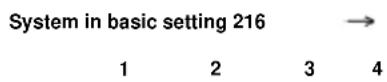
< Indicated on display: (1...4 = display zones)
- O bserve figure displayed in display zone 4.
Specification: xxxxx100 - Allow engine to run at idle until display zone 4 displays (after approx. 30 seconds):
Specification: xxxx1100.
If the display does not indicate as described:
- Press → b utton.
- Check DTC memory, repair Diagnostic Trouble Codes (DTCs) if necessary and then erase DTC memory Page 01-23, DTC memory, checking and erasing.
- Read readiness code Page 01-146. If the DTC memory has been erased or the Motronic Engine Control Module (ECM) - J220- was disconnected from battery (B+) positive, the readiness code must be generated again Page 01-149.
If the display indicates as described:
- Press -C-button.
01-171
Basic setting
Input display group number XXX
System in basic setting 70
1 2 3 4

Work step 14: Evaporative Emissions (EVAP) Canister system solenoid valve 1 diagnosis (Tank ventilation system)
Indicated on display:
- Press buttons -0-, -7- and -0- for "Display group number 70" and confirm entry with -Q- button.
Note:
The engine must not be loaded during this diagnosis, if this occurs the diagnosis will be interrupted and will not start again until the engine is revved-up.
< Indicated on display: (1 to 4 = display zones)
If the diagnosis is initiated by the Motronic Engine Control Module (ECM) -J220- the display in display zone 4 jumps from "Test OFF" to "Test ON".
Note:
This process can take approx. 30 seconds.
- L eave engine running at idle until display zone 4 displays:
Specification: TBV OK..
01-172
Note:
TBV stands for Evaporative Emission (EVAP) Canister Purge RegulatorValve -N80-.
If "TBV n. OK." appears in display zone 4:
- Press → b utton.
- Check DTC memory, repair Diagnostic Trouble Codes (DTCs) if necessary and then erase DTC memory Page 01-23DTC memory, checking and erasing.
- Read readiness code Page 01-146. If the DTC memory has been erased or the Motronic Engine Control Module (ECM) -J220- was disconnected from battery (B+) positive, the readiness code must be generated again Page 01-149.
If no DTC is stored:
- Press buttons -0- and -6- for the function "End output" and confirm entry with the -Q- button.
- Switch off ignition.
- Check breather lines to EVAP canister (may be kinked).
01-173
Basic setting
Input display group number XXX
System in basic setting 77
1 2 3 4

- Check EVAP canister system for leaks:
⇒ Repair Manual, 2.8 Liter VR6 4V Engine Mechanical, Engine Code(s): BDF; Repair Group 20
If "TBV OK." appears in display zone 4:
- Press -C- button.
Work step 15: Secondary air system diagnosis
< Indicated on display:
- Press buttons -0, -7- and -7- for "Display group number 77" and confirm entry with -Q- button.
Note:
The engine must not be loaded during this diagnosis, if this occurs the diagnosis will be aborted and will not start again until the engine is revved-up.
Indicated on display: (1 to 4 = display zones)
If the diagnosis is initiated by the Motronic Engine Control Module (ECM) -J220- the display in display zone 4 jumps from "Test OFF" to "Test ON".
Note:
This process can take approx. 40 seconds.
01-174
- Leave engine running at idle until display zone 4 displays:
Specification: "Syst. OK."
If "Syst.n.OK." appears in display zone 4:
- Press → b utton.
- Check DTC memory, repair Diagnostic Trouble Codes (DTCs) if necessary and then erase DTC memory Page 01-23DTC memory, checking and erasing.
- Read readiness code Page 01-146. If the DTC memory has been erased or the Motronic Engine Control Module (ECM) -J220- was disconnected from battery (B+) positive, the readiness code must be generated again Page 01-149.
If no DTC is stored:
- Press buttons -0- and -6- for function "End output" and confirm entry with -Q- button.
- Switch off ignition.
- Check combi-valve:
⇒ Repair Manual, 2.8 Liter VR6 4V Engine Mechanical, Engine Code(s): BDF; Repair Group 26
01-175
If "Syst. OK." appears in display zone 4:
- Press → b utton.
Work step 16: Read readiness code
- Read readiness code Page 01-146.
01-176
Readiness code, generating (overview)
Work steps 1 to 5:
| Work step/ Diagnosis | Function/group | Test prerequisites | Display zone 1 | Display zone 2 | Display zone 3 | |
| 1 | C heck DTC memory | 02/--- | ♦ Ignition on | --- | --- | --- |
| 2 | E r ase DTC memory | 05/--- | ♦ Ignition on | --- | --- | --- |
| 3 | A d apting Throttle Valve Control Module | 04/60 | ♦ Ignition on | Throt. valve angle angle sensor 1 | Throt. valve angle angle sensor 2 | Learning step counter |
| Specification: | 3...93 % | 97...3 % | 8 | |||
| 4 | R equesting temperature | 08/4 | ♦ Idle speed | Idle speed | Voltage supply for Motronic Engine Control Module (ECM) - J220- | Coolant temperature |
| Specification: | 6 40...720 rpm | 11.5...15.0 V | 85.0...110.0 °C | |||
| 5 | Leak diagnosis | 04/071 | ♦ Idle speed | Reed condition | Text | Text |
| Specification: | Reed open | --- | Check END | |||
01-177
Work steps 6 to 9:
| Work step/ Diagnosis | Function/group | Test prerequisites | Display zone 1 | Display zone 2 | Display zone 3 | |
| 6 | Oxygen Sensor (O2S) control status | 08/30 | ♦ Idle speed | Before Three Way Catalytic Converter (TWC) | After Three Way Catalytic Converter (TWC) | No display |
| Specification: | 111 | xxx | --- | |||
| 7 | Oxygen Sensor (O2S) before Three Way Catalytic Converter (TWC)(Oxygen Sensor (O2S) aging) | 04/34 | ♦ Brakes operated♦ Accelerator in wide openthrottle position. | Engine speed | Three Way Catalytic Converter (TWC) temperature | Dynamic factor of Oxygen Sensor (O2S) before Three Way Catalytic Converter (TWC) |
| Specification: | Approx. 2300 rpm | Greater than 380 °C | 1.00...2.50 | |||
| 8 | Fuel supply system(part load) | 04/216 | ♦ Brakes operated♦ Accelerator in wide openthrottle position. | Engine speed | Oxygen Sensor (O2S) before Three Way Catalytic Converter (TWC) lower part load | Oxygen Sensor (O2S) before Three Way Catalytic Converter (TWC) idle speed |
| Specification: | --- | --- | --- | |||
01-178
| Work step/ Diagnosis | Function/group | Test prerequisites | Display zone 1 | Display zone 2 | Display zone 3 | Display zone 4 | |
| 9 | Oxygen Sensor (O2S) control status | 08/30 | ◆ Idle speed | Before Three Way Catalytic Converter (TWC) | After Three Way Catalytic Converter (TWC) | No display | No display |
| Specification: | xxx | 111 | --- | --- | |||
01-179
Work steps 10 to 11:
| Work step/diagnosis | Function/group | Test prerequisites | Display zone 1 | Display zone 2 | Diszor | |
| 10 | O xygen Sensor (O2S) after Three Way Catalytic Converter (TWC)(Oxygen Sensor (O2S) aging) | 04/43 | ♦ Brakes operated♦ Accelerator in wide openthrottle position. | Engine speed | Three Way Catalytic Converter (TWC) temperature | Oxy Sen (O2S volt Oxy Sen (O2S Three Cata Conv (TV |
| Specification: | Approx. 2300 rpm | Greater than 380 °C | 0.100. \ | |||
| 11 | O xygen Sensor (O2S) after Three Way Catalytic Converter (TWC)(operational readiness) | 04/36 | ♦ Idle speed | Oxygen Sensor (O2S) voltage, Oxygen Sensor (O2S) after Three Way Catalytic Converter (TWC) | Result | No di |
| Specification: | 0.100...0.900 V | B1 P2 OK. | -- | |||
01-180
Work steps 12 to 13:
| Work step/diagnosis | Function/group | Test prerequisites | Display zone 1 | Display zone 2 | Display zone 3 | |
| 12 | T hree Way Catalytic Converter (TWC) | 04/46 | ♦ Brakes operated♦ Accelerator in wide openthrottle position. | Engine speed | Three Way Catalytic Converter (TWC) temperature | Three Way Catalytic Converter (TWC) conversion rate |
| Specification: | Approx. 2300 rpm | Greater than 380 °C | 0.00...0.99 | |||
| 13 | F uel supply system (idle speed) | 04/216 | ♦ Idle speed | Engine speed | Oxygen Sensor (O2S) before Three Way Catalytic Converter (TWC) lower part load | Oxygen Sensor (O2S) before Three Way Catalytic Converter (TWC) idle speed |
| Specification: | --- | --- | --- | |||
01-181
Work steps 14 to 16:
| Work step/diagnosis | Function/group | Test prerequisites | Display zone 1 | Display zone 2 | Display zone 3 | |
| 14 | Evaporative Emission (EVAP)Canister Purge RegulatorValve -N80-(Tank ventilation system) | 04/70 | ♦ Idle speed | Evaporative Emissions (EVAP)Canister regulator valve 1 duty cycle | TBV quality | No display |
| Specification: | --- | --- | --- | |||
| 15 | Secondary air system | 04/77 | ♦ Idle speed | Idle speed | Air mass drawn in | Air mass secondary air system |
| Specification: | 6 40...720 rpm | --- | --- | |||
| 16 | Read readiness code | 15/--- | ♦ Idle speed | --- | --- | --- |
1) TBV stands for Evaporative Emission (EVAP) Canister Purge Regulator Valve -N80-.
Readiness code
Function
The readiness code is an 8-digit number code which displays the status of the emission relevant diagnosis.
When the diagnosis for a system (e.g. secondary air system) has been successfully completed, the corresponding position in the number code will change from 1 to 0.
The diagnosis is performed at regular intervals during normal driving. It is recommended that the readiness code be generated after performing repairs on an emission relevant system, to guarantee that these systems function correctly. If a malfunction is detected during the diagnosis it will be stored in the DTC memory.
Each time the DTC memory is erased or the voltage supply is interrupted the readiness code will be erased.
01-146

Read readiness code
Special tools, workshop equipment, testers, measuring instruments and auxiliary items required

◆ VAG 1551 Scan tool (or VAG 1552 vehicle system tester) with VAG 1551/3 adapter cable
Note:
All functions which could previously be performed with VAG 1551/1552 can also be performed with the vehicle diagnostic, testing and information system VAS 5051.
Work sequence
- Connect VAG 1551 scan tool ((VAG 1552) and select Engine Control Module (ECM) with the "Address word" 01. Engine must be running at idle: (Connecting scan tool and selecting Engine Control Module (ECM) Page 01-12).
Rapid data transfer
HELP
Select function XX

Indicated on display:
- Press buttons -1- and -5- for function "Readiness code" and confirm entry with -Q- button.
01-147
Readiness code

00000000 - Test complete
Must appear on display when all diagnosis functions have been successfully completed:
< Indicated on display:
- Press → button.
- Press buttons -0- and -6- for function "End output" and confirm entry with -Q- button.
- Switch off ignition.
Readiness code

00101101 - Test not complete
Appears on display:
One of the diagnostic checks has not run through successfully:
- Press → b utton.
- G enerate readiness code Page 01-149.
01-148
Significance of figures in 8 digit number block, display zone 1 - Readiness code
| The readiness code is generated only when all display zones show 0 | ||||||||
| 1 | 2 | 3 | 4 | 5 | 6 | 7 | 8 | Diagnostic function |
| 0 | Three Way Catalytic Converter (TWC) | |||||||
| 0 | Three Way Catalytic Converter (TWC) heating (currently no diagnosis/always "0") | |||||||
| 0 | Evaporative Emissions (EVAP) Canister system (Tank ventilation system) | |||||||
| 0 | Secondary air system | |||||||
| 0 | Air conditioner (currently no diagnosis/always "0") | |||||||
| 0 | Oxygen Sensor (O2S)s | |||||||
| 0 | Oxygen Sensor (O2S) heating | |||||||
| 0 | Exhaust gas recirculation (not installed/always "0") | |||||||
01-149
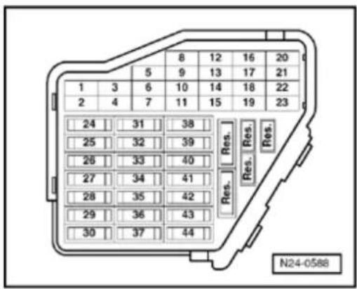
Generating readiness code
Special tools, workshop equipment, testers, measuring instruments and auxiliary items required

◆ VAG 1551 scan tool (or VAG 1552) with VAG 1551/3 Adapter cable
Note:
All functions which could previously be performed with VAG 1551/1552 can also be performed with the vehicle diagnostic, testing and information system VAS 5051.
Test prerequisites

- All fuses must be OK.
01-150

natural_image
Technical line drawing of an electrical connector with multiple ports and wiring (no text or symbols)
• The main fuses must be OK.
- The battery voltage must be at least 11.5 V.
- If the vehicle is equipped with air conditioning, this must be switched off.
- Selector lever must be in position "P" or "N" on vehicles with an automatic transmission.
- Exhaust system between Three Way Catalytic Converter (TWC) and cylinder head must be free of leaks
- Ignition switched on, engine not running.
- Fuel Pump (FP) relay -J17- must be OK., checking:
⇒ Electrical Wiring Diagrams, Troubleshooting & Component Locations
- The signal from Brake Light Switch -F- and Brake Vacuum Vent Valve Switch -F47- -F85- must be OK., checking Page 24-206.
- Engine Coolant Temperature (ECT) must be 85...110 °C ⇒display group 4, display zone 3.
- Intake Air Temperature (IAT) less than 80^ C display group 4, display zone 4.
- Three Way Catalytic Converter (TWC) temperature must be at least 380 °C ⇒d isplay group 34, display zone 2.
01-151
Work sequence
- Connect VAG 1551 scan tool (or VAG 1552). Then switch ignition on and select Motronic Engine Control Module (ECM) -J220- with the "Address word" 01. (Connecting scan tool and selecting Engine Control Module (ECM) Pa 01-12).
Work step 1: Check DTC memory
Rapid data transfer
HELP
Select function XX
Indicated on display:
- Operate scan tool taking into account the information on the display:
- Press buttons -0- and -2- for function "Check DTC memory" and confirm entry with Q button
X Diagnostic Trouble Codes (DTCs) detected!
The number of Diagnostic Trouble Codes (DTCs stored or "No DTC detected!" will be shown on the display.
If a DTC is stored:
01-152
Repair Diagnostic Trouble Codes (DTCs) printed out using DTC table:
♦ SAE P0 codes ⇒ Page 01-30,
♦ SAE P1 codes ⇒ Page 01-58,
♦ SAE P2 codes ⇒ Page 01-98,
♦ SAE P3 codes ⇒ Page 01-99.
If no DTC is stored:
- Press → b utton.
- Continue with work step 3
Work step 2: Erase DTC memory
Rapid data transfer HELP Select function XX
< Indicated on display:
- Press buttons -0- and -5- for function "Erase DTC memory" and confirm entry with -Q- button.
Note:
The readiness code is reset or erased each time DTC memory is erased.
Rapid data transfer → DTC memory is erased!
Indicated on display:
01-153
Note:
If the ignition is switched off between "Check DTC memory" and "Erase DTC memory" the DTC memory will not be erased.
- Press → b utton.
Work step 3: Adjust the Throttle Valve Control Module -J338- to the Motronic Engine Control Module (ECM) -J220-
Rapid data transfer HELP
Select function XX
Basic setting
Input display group number XXX
System in basic setting 60 →
xxx.x % xxx.x % x ADP. runs
System in basic setting 60 →
< Indicated on display:
- Press buttons -0- and -4- for function "Initiate basic setting" and confirm entry with -Q- button.
< Indicated on display:
- Press buttons -0-, -6- and -0- for "Display group number 60" and confirm entry with -Q- button.
Indicated on display: (1 to 4 = display zones)
- Check specifications in display zones 3 and 4:
Display zone 3: 0 to 8
Display zone 4: ADP. runs, ADP. OK.
Indicated on display: (1 to 4 = display zones)
01-154
- Terminate engine basic setting at earliest after 30 seconds by pressing → button.
If the display does not indicate as described:
- Check Throttle Valve Control Module -J338- Page 24-59.
If the display indicates as described:
- Start engine and run at idle.
Note:
Engine must not be switched again off during work sequence.
Work step 4: Requesting temperature
Rapid data transfer
HELP
Select function XX

Indicated on display:
- Press buttons -0- and -8- for function "Read measured value (data) block" and confirm entry with Q button.
Read measured value block
Input display group number XXX

Indicated on display:
- Press buttons -0-, -0- and -4- for "Display group number 4" and confirm entry with -Q- button.
Read measured value block 4

1 2 3 4

Indicated on display: (1 to 4 = display zones)
01-155
- Read Engine Coolant Temperature value in display zone 3.
Specification: 85 to 110 °C
- Read Intake Air Temperature value in display zone 4.
Specification: Ambient temperature less than 80 °C
If the specifications are obtained:
- Press → b utton.
Work step 5: Evaporative Emissions (EVAP) Canister system diagnosis (Tank ventilation system)
Rapid data transfer
HELP

Select function XX
Indicated on display:
- Press buttons -0- and -4- for function "Initiate basic setting" and confirm entry with -Q- button.
Basic setting

Input display group number XXX
Indicated on display:
- Press buttons -0-, -7- and -1- for "Display group number 71" and confirm entry with -Q- button.
Note:
The engine must not be loaded during this diagnosis, if this occurs the diagnosis will be interrupted and will not start again until the engine is revved-up.
01-156
| System in basic setting 71 | → | ||
| 1 | 2 | 3 | 4 |
Indicated on display: (1 to 4 = display zones)
If "Reed op." appears in display zone 1:
- O pen fuel tank filler cap briefly to release pressure in fuel tank. This will close reed terminal.
If the diagnosis is initiated by the Motronic Engine Control Module (ECM) -J220- the display in display zone 4 jumps from "Test OFF" to "Test ON".
- L eave engine running at idle until specification "Sys. OK." is displayed in display zone 4.
Note:
If the display in display zone 4 jumps from "Test OFF" to "Test ON" during the diagnosis, repeat the diagnosis again. When repeating the diagnosis, the diagnosis can take up to 60 seconds before the display in display zone 4 jumps from "Test OFF" to "Test ON".
If "Sm leak or La leak" (meaning Small leak or Large leak) appears in display zone 2 and "Sys. n.OK." appears in display zone 4:
- Press → b utton.
01-157
- Check DTC memory, repair Diagnostic Trouble Codes (DTCs) if necessary and then erase DTC memory Page 01-23DTC memory, checking and erasing.
- Read readiness code Page 01-146. If the DTC memory has been erased or the Motronic Engine Control Module (ECM) -J220- was disconnected from battery (B+) positive, the readiness code must be generated again Page 01-149.
If no DTC is stored:
- Check Evaporative Emissions (EVAP) Canister system for leaks:
⇒ Repair Manual, 2.8 Liter VR6 4V Engine Mechanical, Engine Code(s): BDF; Repair Group 20
If "Sys. OK." appears in display zone 4:
- Press → b utton.
Work step 6: Oxygen Sensor (O2S) control diagnosis status before Three Way Catalytic Converter (TWC)
Rapid data transfer
HELP

Indicated on display:
Select function XX
- Press buttons -0- and -8- for function "Read measured value (data) block" and confirm entry with -Q- button.
Read measured value block

Indicated on display:
Input display group number XXX
01-158

- Press buttons -0-, -3- and -0- for "Display group number 30" and confirm entry with -Q- button.
Indicated on display: (1 to 2 = display zones)
- Check Oxygen Sensor (O2S) control status before Three Way Catalytic Converter (TWC) (display zone 1):
Specification: 111
Significance of figures in 3 digit number block Page 01-217.
Note:
The bits in display zones 1 will not be set to 1 until the Three Way Catalytic Converter (TWC) temperature rises above 380^ C ( display groups 34, display zone 2).
If the specification is not obtained:
- Press → b utton.
- Check Oxygen Sensor (O2S) heater of Oxygen Sensor (O2S) before Three Way Catalytic Converter (TWC) Page 24-38.
If the specification is obtained:
- Press → b utton.
01-159
| Rapid data transfer | HELP |
| Select function XX |
| Basic setting |
| Input display group number XXX |
| System in basic setting 34 | |||
| 1 | 2 | 3 | |
Work step 7: Oxygen Sensor (O2S) aging diagnosis of Oxygen Sensor (O2S) before Three Way Catalytic Converter (TWC)
Indicated on display:
- Press buttons -0- and -4- for function "Initiate basic setting" and confirm entry with -Q- button.
< Indicated on display:
- Press buttons -0-, -3- and -4- for "Display group number 34" and confirm entry with -Q- button.
Indicated on display: (1...4 = display zones)
- Depress brake pedal and hold.
- Depress accelerator down to wide open throttle position.
Engine speed will be increased by Motronic Engine Control Module (ECM) -J220- to approx. 2300 rpm. - Depress brake pedal and accelerator down until display in display zone 4 jumps from "Test OFF" to "Test ON". When performing this test Three Way Catalytic Converter (TWC) temperature in display zone 2 must be at least 380 °C.
01-160
Note:
This process can take approx. 90 seconds.
- Depress brake pedal and accelerator down until display zone 4 displays specification "B1-P1 OK.".
- Release brake and accelerator pedals.
If "B1 P1 n.OK." appears in display zone 4:
- Press → b utton.
- Check DTC memory, repair Diagnostic Trouble Codes (DTCs) if necessary and then erase DTC memory Page 01-23DTC memory, checking and erasing.
- Read readiness code Page 01-146. If the DTC memory has been erased or the Motronic Engine Control Module (ECM) -J220- was disconnected from battery (B+) positive, the readiness code must be generated again Page 01-149.
If no DTC is stored:
- Check aging of Oxygen Sensor (O2S) before Three Way Catalytic Converter (TWC) Page 24-150.
If "B1 P1 OK." appears in display zone 4:
- Press C button.
01-161
Basic setting
Input display group number XXX
System in basic setting 216
1 2 3 4
Work step 8: Fuel supply system diagnosis (part load)
< Indicated on display:
- Press buttons -2-, -1- and -6- for "Display group number 216" and confirm entry with -Q- button.
< Indicated on display: (1 to 4 = display zones)
- Depress brake pedal and hold.
- Depress accelerator down to wide open throttle position.
Engine speed will be increased by Motronic Engine Control Module (ECM) -J220- to approx. 2300 rpm.
- Depress brake pedal and accelerator down until display zone 4 displays (after approx. 75 seconds) specification "xxxxx100".
- Release brake and accelerator pedals.
If the display does not indicate as described:
- Press → b utton.
01-162
- Check DTC memory, repair Diagnostic Trouble Codes (DTCs) if necessary and then erase DTC memory Page 01-23DTC memory, checking and erasing.
- Read readiness code Page 01-146. If the DTC memory has been erased or the Motronic Engine Control Module (ECM) -J220- was disconnected from battery (B+) positive, the readiness code must be generated again Page 01-149.
If the display indicates as described:
- Press → b utton.
Work step 9: Oxygen Sensor (O2S) control diagnosis status after Three Way Catalytic Converter (TWC)
Rapid data transfer
HELP

Select function XX
Indicated on display:
- Press buttons -0- and -8- for function "Read measured value (data) block" and confirm entry with -Q- button.
Read measured value block

Input display group number XXX
Indicated on display:
- Press buttons -0-, -3- and -0- for "Display group number 30" and confirm entry with -Q- button.
Read measured value block 30

1
2
Indicated on display: (1...2 = display zones)
01-163
- Check Oxygen Sensor (O2S) control status after Three Way Catalytic Converter (TWC) (display zone 2): Specification: 111
Significance of figures in 3 digit number block Page 01-217.
Note:
The bits in display zone 2 will not be set to 1 until the Three Way Catalytic Converter (TWC) temperature rises above 380^ ( display groups 34, display zone 2).
If the specification is not obtained:
- Press → b utton.
- Check Oxygen Sensor (O2S) heater of Oxygen Sensor (O2S) after Three Way Catalytic Converter (TWC) Page 24-45.
If the specification is obtained:
- Press → b utton.
Work step 10: Oxygen Sensor (O2S) aging diagnosis of Oxygen Sensor (O2S) after Three Way Catalytic Converter (TWC)
Rapid data transfer
Select function XX
HELP

Indicated on display:
- Press buttons -0- and -4- for function "Initiate basic setting" and confirm entry with -Q- button.
01-164
Basic setting
Input display group number XXX
| System in basic setting 43 | |||
| 1 | 2 | 3 | |
Indicated on display:
- Press buttons -0-, -4- and -3- for "Display group number 43" and confirm entry with -Q- button.
< Indicated on display: (1 to 4 = display zones)
- Depress brake pedal and hold.
- Depress accelerator down to wide open throttle position.
Engine speed will be increased by Motronic Engine Control Module (ECM) -J220- to approx. 2300 rpm.
- Depress and hold brake pedal and accelerator until display in display zone 4 jumps from "Test OFF" to "Test ON", when performing this test the Three Way Catalytic Converter (TWC) temperature in display zone 2 must be at least 380 °C.
Note:
This process can take approx. 30 seconds.
- Depress and hold brake pedal and accelerator until display zone 4 displays specification "B1 P2 OK.".
- Release brake and accelerator pedals.
01-165
If "B1 P2 n.OK." appears in display zone 4:
- Press → b utton.
- Check DTC memory, repair Diagnostic Trouble Codes (DTCs) if necessary and then erase DTC memory Page 01-23 DTC memory, checking and erasing.
- Read readiness code Page 01-146. If the DTC memory has been erased or the Motronic Engine Control Module (ECM) -J220- was disconnected from battery (B+) positive, the readiness code must be generated again Page 01-149.
If no DTC is stored:
- Check aging of Oxygen Sensor (O2S) after Three Way Catalytic Converter (TWC) Page 24-154.
If "B1 P2 OK." appears in display zone 4:
- Press -C- button.
Work step 11: Oxygen Sensor (O2S) diagnosis after Three Way Catalytic Converter (TWC) (operational readiness)
Basic setting
Input display group number XXX
Indicated on display:
- Press buttons -0-, -3- and -6- for "Display group number 36" and confirm entry with -Q- button.
01-166
| System in basic setting 36 | → |
| 1 | 2 |
< Indicated on display: (1...2 = display zones)
If the diagnosis is initiated by the Motronic Engine Control Module (ECM) -J220- the display in display zone 2 jumps from "Test OFF" to "Test ON".
- L eave engine running at idle until display zone 2 shows specification "B1 P2 OK.".
Note:
This process can take approx. 30 seconds.
If "B1 P2 n.OK." appears in display zone 4:
- Press → b utton.
- Check DTC memory, repair Diagnostic Trouble Codes (DTCs) if necessary and then erase DTC memory Page 01-23, DTC memory, checking and erasing.
- Read readiness code Page 01-146. If the DTC memory has been erased or the Motronic Engine Control Module (ECM) - J220- was disconnected from battery (B+) positive, the readiness code must be generated again Page 01-149.
01-167
If no DTC is stored:
- Check Oxygen Sensor (O2S) and Oxygen Sensor (O2S) control after Three Way Catalytic Converter (TWC) Page 24-140
If "B1 P2 OK." appears in display zone 4:
- Press -C-button.
Work step 12: Three Way Catalytic Converter (TWC) diagnosis (checking conversion)
Note:
The diagnosis will only be ended if the Oxygen Sensor (O2S) aging diagnosis for Oxygen Sensor (O2S)s before and after Three Way Catalytic Converter (TWC) is first successfully completed.
Basic setting
Input display group number XXX

Indicated on display:
- Press buttons -0-, -4- and -6- for "Display group number 46" and confirm entry with -Q- button.
System in basic setting 46
1 2 3 4

Indicated on display: (1 to 4 = display zones)
- Depress brake pedal and hold.
- Depress accelerator down to wide open throttle position.
Engine speed will be increased by Motronic Engine Control Module (ECM) -J220- to approx. 2300 rpm.
01-168
Only continue with the test when:
- The Three Way Catalytic Converter (TWC) temperature is above 380 °C (display zone 2).
- Depress brake pedal and accelerator down and hold until display in display zone 4 jumps from "Test OFF" to "Test ON".
Note:
This process can take approx. 80 seconds.
- Depress and hold brake pedal and accelerator until display zone 4 displays specification "Cat. B1 OK.".
- Release brake and accelerator pedals.
If "CatB1 n.OK." appears in display zone 4:
- Press → b utton.
- Check DTC memory, repair Diagnostic Trouble Codes (DTCs) if necessary and then erase DTC memory Page 01-23DTC memory, checking and erasing.
01-169
- Read readiness code Page 01-146. If the DTC memory has been erased or the Motronic Engine Control Module (ECM) -J220- was disconnected from battery (B+) positive, the readiness code must be generated again Page 01-149.
If no DTC is stored:
- Press buttons -0- and -6- for the function "End output" and confirm entry with the -Q- button.
- Switch off ignition.
- Replace front exhaust pipe with Three Way Catalytic Converter (TWC):
⇒ Repair Manual, 2.8 Liter VR6 4V Engine Mechanical, Engine Code(s): BDF; Repair Group 26
If "Cat B1 OK." appears in display zone 4:
- Press -C-button.
Work step 13: Fuel supply system diagnosis (idle speed)
Basic setting
Input display group number XXX
< Indicated on display:
- Press buttons -2-, -1- and -6- for "Display group number 216" and confirm entry with -Q- button.
01-170
| System in basic setting 216 | → | ||
| 1 | 2 | 3 | 4 |
< Indicated on display: (1...4 = display zones)
- O bserve figure displayed in display zone 4.
Specification: xxxxx100 - Allow engine to run at idle until display zone 4 displays (after approx. 30 seconds):
Specification: xxxx1100.
If the display does not indicate as described:
- Press → b utton.
- Check DTC memory, repair Diagnostic Trouble Codes (DTCs) if necessary and then erase DTC memory Page 01-23, DTC memory, checking and erasing.
- Read readiness code Page 01-146. If the DTC memory has been erased or the Motronic Engine Control Module (ECM) - J220- was disconnected from battery (B+) positive, the readiness code must be generated again Page 01-149.
If the display indicates as described:
- Press -C-button.
01-171
Basic setting
Input display group number XXX
System in basic setting 70
1 2 3 4

Work step 14: Evaporative Emissions (EVAP) Canister system solenoid valve 1 diagnosis (Tank ventilation system)
Indicated on display:
- Press buttons -0-, -7- and -0- for "Display group number 70" and confirm entry with -Q- button.
Note:
The engine must not be loaded during this diagnosis, if this occurs the diagnosis will be interrupted and will not start again until the engine is revved-up.
< Indicated on display: (1 to 4 = display zones)
If the diagnosis is initiated by the Motronic Engine Control Module (ECM) -J220- the display in display zone 4 jumps from "Test OFF" to "Test ON".
Note:
This process can take approx. 30 seconds.
- L eave engine running at idle until display zone 4 displays:
Specification: TBV OK..
01-172
Note:
TBV stands for Evaporative Emission (EVAP) Canister Purge RegulatorValve -N80-.
If "TBV n. OK." appears in display zone 4:
- Press → b utton.
- Check DTC memory, repair Diagnostic Trouble Codes (DTCs) if necessary and then erase DTC memory Page 01-23DTC memory, checking and erasing.
- Read readiness code Page 01-146. If the DTC memory has been erased or the Motronic Engine Control Module (ECM) -J220- was disconnected from battery (B+) positive, the readiness code must be generated again Page 01-149.
If no DTC is stored:
- Press buttons -0- and -6- for the function "End output" and confirm entry with the -Q- button.
- Switch off ignition.
- Check breather lines to EVAP canister (may be kinked).
01-173
Basic setting
Input display group number XXX
System in basic setting 77
1 2 3 4

- Check EVAP canister system for leaks:
⇒ Repair Manual, 2.8 Liter VR6 4V Engine Mechanical, Engine Code(s): BDF; Repair Group 20
If "TBV OK." appears in display zone 4:
- Press -C- button.
Work step 15: Secondary air system diagnosis
< Indicated on display:
- Press buttons -0, -7- and -7- for "Display group number 77" and confirm entry with -Q- button.
Note:
The engine must not be loaded during this diagnosis, if this occurs the diagnosis will be aborted and will not start again until the engine is revved-up.
Indicated on display: (1 to 4 = display zones)
If the diagnosis is initiated by the Motronic Engine Control Module (ECM) -J220- the display in display zone 4 jumps from "Test OFF" to "Test ON".
Note:
This process can take approx. 40 seconds.
01-174
- Leave engine running at idle until display zone 4 displays:
Specification: "Syst. OK."
If "Syst.n.OK." appears in display zone 4:
- Press → b utton.
- Check DTC memory, repair Diagnostic Trouble Codes (DTCs) if necessary and then erase DTC memory Page 01-23DTC memory, checking and erasing.
- Read readiness code Page 01-146. If the DTC memory has been erased or the Motronic Engine Control Module (ECM) -J220- was disconnected from battery (B+) positive, the readiness code must be generated again Page 01-149.
If no DTC is stored:
- Press buttons -0- and -6- for function "End output" and confirm entry with -Q- button.
- Switch off ignition.
- Check combi-valve:
⇒ Repair Manual, 2.8 Liter VR6 4V Engine Mechanical, Engine Code(s): BDF; Repair Group 26
01-175
If "Syst. OK." appears in display zone 4:
- Press → b utton.
Work step 16: Read readiness code
- Read readiness code Page 01-146.
01-176
Readiness code, generating (overview)
Work steps 1 to 5:
| Work step/ Diagnosis | Function/group | Test prerequisites | Display zone 1 | Display zone 2 | Display zone 3 | |
| 1 | C heck DTC memory | 02/--- | ♦ Ignition on | --- | --- | --- |
| 2 | E r ase DTC memory | 05/--- | ♦ Ignition on | --- | --- | --- |
| 3 | A d apting Throttle Valve Control Module | 04/60 | ♦ Ignition on | Throt. valve angle angle sensor 1 | Throt. valve angle angle sensor 2 | Learning step counter |
| Specification: | 3...93 % | 97...3 % | 8 | |||
| 4 | R equesting temperature | 08/4 | ♦ Idle speed | Idle speed | Voltage supply for Motronic Engine Control Module (ECM) - J220- | Coolant temperature |
| Specification: | 6 40...720 rpm | 11.5...15.0 V | 85.0...110.0 °C | |||
| 5 | Leak diagnosis | 04/071 | ♦ Idle speed | Reed condition | Text | Text |
| Specification: | Reed open | --- | Check END | |||
01-177
Work steps 6 to 9:
| Work step/ Diagnosis | Function/group | Test prerequisites | Display zone 1 | Display zone 2 | Display zone 3 | |
| 6 | Oxygen Sensor (O2S) control status | 08/30 | ♦ Idle speed | Before Three Way Catalytic Converter (TWC) | After Three Way Catalytic Converter (TWC) | No display |
| Specification: | 111 | xxx | --- | |||
| 7 | Oxygen Sensor (O2S) before Three Way Catalytic Converter (TWC)(Oxygen Sensor (O2S) aging) | 04/34 | ♦ Brakes operated♦ Accelerator in wide openthrottle position. | Engine speed | Three Way Catalytic Converter (TWC) temperature | Dynamic factor of Oxygen Sensor (O2S) before Three Way Catalytic Converter (TWC) |
| Specification: | Approx. 2300 rpm | Greater than 380 °C | 1.00...2.50 | |||
| 8 | Fuel supply system(part load) | 04/216 | ♦ Brakes operated♦ Accelerator in wide openthrottle position. | Engine speed | Oxygen Sensor (O2S) before Three Way Catalytic Converter (TWC)lower part load | Oxygen Sensor (O2S) before Three Way Catalytic Converter (TWC)idle speed |
| Specification: | --- | --- | --- | |||
01-178
| Work step/ Diagnosis | Function/group | Test prerequisites | Display zone 1 | Display zone 2 | Display zone 3 | Display zone 4 | |
| 9 | Oxygen Sensor (O2S) control status | 08/30 | ◆ Idle speed | Before Three Way Catalytic Converter (TWC) | After Three Way Catalytic Converter (TWC) | No display | No display |
| Specification: | xxx | 111 | --- | --- | |||
01-179
Work steps 10 to 11:
| Work step/diagnosis | Function/group | Test prerequisites | Display zone 1 | Display zone 2 | Diszor | |
| 10 | O xygen Sensor (O2S) after Three Way Catalytic Converter (TWC)(Oxygen Sensor (O2S) aging) | 04/43 | ♦ Brakes operated♦ Accelerator in wide openthrottle position. | Engine speed | Three Way Catalytic Converter (TWC) temperature | Oxy Sen (O2S volt Oxy Sen (O2S Three Cata Conv (TV |
| Specification: | Approx. 2300 rpm | Greater than 380 °C | 0.100. \ | |||
| 11 | O xygen Sensor (O2S) after Three Way Catalytic Converter (TWC)(operational readiness) | 04/36 | ♦ Idle speed | Oxygen Sensor (O2S) voltage, Oxygen Sensor (O2S) after Three Way Catalytic Converter (TWC) | Result | No di |
| Specification: | 0.100...0.900 V | B1 P2 OK. | -- | |||
01-180
Work steps 12 to 13:
| Work step/diagnosis | Function/group | Test prerequisites | Display zone 1 | Display zone 2 | Display zone 3 | |
| 12 | T hree Way Catalytic Converter (TWC) | 04/46 | ♦ Brakes operated♦ Accelerator in wide openthrottle position. | Engine speed | Three Way Catalytic Converter (TWC) temperature | Three Way Catalytic Converter (TWC) conversion rate |
| Specification: | Approx. 2300 rpm | Greater than 380 °C | 0.00...0.99 | |||
| 13 | F uel supply system (idle speed) | 04/216 | ♦ Idle speed | Engine speed | Oxygen Sensor (O2S) before Three Way Catalytic Converter (TWC) lower part load | Oxygen Sensor (O2S) before Three Way Catalytic Converter (TWC) idle speed |
| Specification: | --- | --- | --- | |||
01-181
Work steps 14 to 16:
| Work step/diagnosis | Function/group | Test prerequisites | Display zone 1 | Display zone 2 | Display zone 3 | |
| 14 | Evaporative Emission (EVAP)Canister Purge RegulatorValve -N80-(Tank ventilation system) | 04/70 | ♦ Idle speed | Evaporative Emissions (EVAP)Canister regulator valve 1 duty cycle | TBV quality | No display |
| Specification: | --- | --- | --- | |||
| 15 | Secondary air system | 04/77 | ♦ Idle speed | Idle speed | Air mass drawn in | Air mass secondary air system |
| Specification: | 6 40...720 rpm | --- | --- | |||
| 16 | Read readiness code | 15/--- | ♦ Idle speed | --- | --- | --- |
1) TBV stands for Evaporative Emission (EVAP) Canister Purge Regulator Valve -N80-.
Measured value (data) blocks
Safety precautions
Observe following if test and measuring instruments are required during a road test:
◆ Test and measuring instruments must be secured to rear seat and operated by a 2nd person from this location.
If test and measuring instruments are operated from front passenger's seat and the vehicle is involved in an accident, there is a possibility that the person sitting in this seat may receive serious injuries when the airbag is triggered.
01-183
Read measured value (data) block
The measured values in the functions read measured value block and basic setting are described during the individual component test. This table serves only as an overview.
Special tools and equipment


◆ VAG 1551 scan tool (or VAG 1552 vehicle system tester) with VAG 1551/3 adapter cable
Note:
All functions which could previously be performed with VAG 1551/1552 can also be performed with the vehicle diagnostic, testing and information system VAS 5051.

Test requirements

• The fuses must be OK.
01-184

natural_image
Technical line drawing of an electrical connector with multiple ports and wiring (no text or symbols)
• The main fuses must be OK.
- The battery voltage must be at least 11.5 V.
• Ground (GND) connection between engine and body must be OK.
- All electrical devices, e.g. lights and rear window defroster must be switched off.
- If the vehicle is equipped with air conditioning, this must be switched off.
- Selector lever must be in position "P" or "N" on vehicles with an automatic transmission.
- Coolant temperature must be at least 85 °C, ⇒d isplay group 1, display zone 2.
- Three Way Catalytic Converter (TWC) temperature must be at least 380 °C, ⇒d isplay group 46, display zone 2.
- No Diagnostic Trouble Codes (DTCs) must be stored in DTC memory Page 01-23, DTC memory, checking and erasing.
01-185
Work sequence
- Connect VAG 1551 scan tool ((VAG 1552) and select Engine Control Module (ECM) with the "Address word" 01. When doing this the engine must be running at idle: (Connecting scan tool and selecting Engine Control Module (ECM) Page 01-12).
Rapid data transfer
HELP

Indicated on display:
Select function XX
- Press buttons -0- and -8- for function "Read measured value (data) block" and confirm entry with -Q- button.
Read measured value (data) block

Indicated on display:
Input display group number XXX
- Select required display group number.
Note:
The display group number 1 is an example, to illustrate the sequence.
- Press buttons -0-, -0- and -1- for "Display group number 1" and confirm entry with -Q- button.
01-186
| Read measured value block 1 | → | ||
| 1 | 2 | 3 | 4 |
< Indicated on display: (1...4 = display zones)
Note:
To change to another display group proceed as follows:
| Display group | VAG 1551 | VAG 1552 |
| Higher | Press button -3- | ↑-Press button |
| Lower | Press button -1- | Press ↓ button |
| Skip | Press button -C- | Press button -C- |
- If the specifications in all display zones are obtained, → - press button.
| Rapid data transfer | HELP |
| Select function XX |
Indicated on display:
- Press buttons -0- and -6- for the function "End output" and confirm entry with the -Q- button.
Note:
Measured value blocks which are not described in this chapter are currently only intended for research and development and production. The values displayed are not relevant for service department troubleshooting.
01-187
Measured value blocks, display groups 0...9 - Basic functions, evaluating
| Display group 1 - Basic functions | ||||||
| • Engine running at idle | ||||||
| Read measured value block 1→ Indicated on display | ||||||
| xxxx xxx.x xx.x xxxxxxxx rpm °C % | ||||||
| 1 | 2 | 3 | 4 | ◀ Display zones | Specification | Evaluation |
| Prerequisites for basic settings | 11111111 | ⇒ Page 01-189 | ||||
| Oxygen Sensor (O2S) control before Three Way Catalytic Converter (TWC) | -10.0...10.0 % | ⇒ Page 01-224 | ||||
| Coolant temperature | 80.0...110.0°C | ⇒ Page 01-195 | ||||
| Engine speed (idle speed) | 640...720 rpm | ⇒ Page 01-188 | ||||
01-188
Evaluating display group 1, display zone 1 - Engine speed (idle speed)
| VAG 1551 displayLess than specified | Possible cause◆ Throttle Valve Control Module - J338- sticking/faulty◆ Large amount of unmetered air (cannot be compensated for by the idling stabilization) | Corrective action- Check Throttle Valve Control Module -J338- ⇒ Page 24-59- Check intake air system for leaks ⇒ Page 24-121- Perform idle speed check ⇒ Page 24-125 |
| Greater than specified | ◆ Idle speed not detected | - Check DTC memory ⇒ Page 01-23, DTC memory, checking and erasing |
| ◆ Large amount of unmetered air (cannot be compensated for by the idling stabilization) | - Check intake air system for leaks ⇒ Page 24-121 | |
| ◆ Throttle Valve Control Module - J338- sticking/faulty | - Check Throttle Valve Control Module -J338- ⇒ Page 24-59- Perform idle speed check ⇒ Page 24-125 | |
| ◆ Supply voltage too low, engine tries to reduce charge difference through increased idle speed | - Evaluation ⇒ Page 01-194, display group 4, display zone 2 |
01-189
Significance of figures in 8 digit number block, display zone 4 - Adjustment conditions
| Significance if display = 1 | ||||||||
| 1 | 2 | 3 | 4 | 5 | 6 | 7 | 8 | Significance |
| 1 | Coolant temperature above 80 °C | |||||||
| 1 | Speed below 2000 rpm | |||||||
| 1 | Throttle valve closed | |||||||
| 1 | Oxygen Sensor (O2S) control active | |||||||
| 1 | Idle speed detected | |||||||
| 1 | Air conditioner compressor switched off | |||||||
| 1 | Coolant temperature above 380 °C | |||||||
| 1 | No Diagnostic Trouble Codes (DTCs) detected by On Board Diagnostic (OBD) | |||||||
01-190
| Display group 2 - Basic functions - Mass Air Flow (MAF) Sensor | ||||||
| • Engine running at idle | ||||||
| Read measured value → Indicated on block 2xxxx rpm xxx.x % --- xx.x g/s | ||||||
| 1 | 2 | 3 | 4 | ◀ Display zones | Specification | Evaluation |
| Air mass drawn in | 3.0...5.0 g/s | ⇒ Page 01-191 | ||||
| No display | --- | --- | ||||
| Engine load | 12.0...26.0 % | ⇒ Page 01-201 | ||||
| Engine speed (idle speed) | 640...720 rpm | ⇒ Page 01-188 | ||||
Note on display zone 2:
The engine load at idling is given as the specification.
Note on display zone 4:
Displayed is the air mass measured by the Mass Air Flow (MAF) Sensor -G70-.
01-191
Evaluating display group 2, display zone 4 - Mass Air Flow (MAF)
| Appears on display | Possible cause | Corrective action |
| Less than specified | ◆ Large amount of unmetered air between intake manifold and Mass Air Flow (MAF) Sensor -G70- | - Repair unmetered air |
| Greater than specified | ◆ Gear selected (automatic transmission)◆ Engine loaded due to accessories | - Place selector lever in P or N- Eliminate load (air conditioner, power assisted steering etc.) |
01-192
| Display group 3 - Basic function - Mass Air Flow (MAF) | ||||||
| • Engine running at idle | ||||||
| Read measured value → Indicated on block 3xxxx xx.x xx.x xx.xrpm g/s % °C | ||||||
| 1 | 2 | 3 | 4 | ◀ Display zones | Specification | Evaluation |
| Ignition timing angle | 4.0...15.0° BTDC | --- | ||||
| Throttle valve angleAngle sensor -1- for throttle drive -G187- | 0.2...4.0% | ⇒ Page 01-202 | ||||
| Air mass drawn in | 3.0...5.0 g/s | ⇒ Page 01-191 | ||||
| Engine speed (idle speed) | 640...720 rpm | ⇒ Page 01-188 | ||||
Note on display zone 2:
Displayed is the air mass measured by the Mass Air Flow (MAF) Sensor -G70-.
Note on display zone 3:
Display values must be approx. 100% when accelerator pedal is fully depressed.
01-193
| Display group 4 - Basic functions | ||||||
| • Engine running at idle | ||||||
| Read measured value → Indicated on block 4xxxx xx.xxx xxx.x xxx.xrpm V °C °C | Indicated on display | |||||
| 1 | 2 | 3 | 4 | ◀ Display zones | Specification | Evaluation |
| Intake air temperature | -37.0...126.0°C | ⇒ Page 01-196 | ||||
| Coolant temperature | 80.0...110.0 °C | ⇒ Page 01-195 | ||||
| Voltage supply for Motronic Engine Control Module (ECM) -J220- | 11.500...15.000V | ⇒ Page 01-194 | ||||
| Engine speed (idle speed) | 640...720 rpm | ⇒ Page 01-188 | ||||
Note on display zone 4:
The total temperature range is given as the specification. The displayed value must be above ambient temperature.
01-194
Evaluating display group 4, display zone 2 - control module voltage supply
| Appears on display | Possible cause | Corrective action |
| Less than specified | ♦ Alternator faulty, battery charge state low | - Check alternator and battery voltage, charge battery:⇒ Repair Manual, Electrical Equipment; Repair Group 27 |
| ♦ Battery heavily loaded shortly after starting due to high charging current and accessories | - Increase revs slightly for a few minutes and switch off accessories | |
| ♦ Transfer resistance in current supply or the Motronic Engine Control Module (ECM) -J220- Ground (GND) connection | - Check Motronic Engine Control Module (ECM) -J220-voltage supply ⇒ Page 24-163 | |
| ♦ Current draw when ignition is off | - Eliminate current draw | |
| Greater than specified | ♦ Voltage control on alternator faulty | - Check voltage control, replace if necessary:⇒ Repair Manual, Electrical Equipment; Repair Group 27 |
| ♦ Excess voltage due to slave starting or quick charging unit | - Check DTC memory ⇒ Page 01-23, DTC memory, checking and erasing |
01-195
Evaluating display group 4, display zone 3 - Engine Coolant Temperature (ECT)
| Appears on display | Possible cause | Corrective action |
| Less than specified | ♦ Engine too cold | - If necessary perform road test |
| ♦ Engine Coolant Temperature (ECT) sensor -G62- faulty | - Check Engine Coolant Temperature (ECT) sensor -G62- ⇒ Page 24-69 | |
| Greater than specified | ♦ Radiator contaminated | - Clean radiator |
| ♦ Coolant fan not functioning | - Check coolant fan:⇒ Repair Manual, 2.8 Liter VR6 4V Engine Mechanical, Engine Code(s): BDF; Repair Group 19 | |
| ♦ Thermostat sticking/faulty | - Check thermostat:⇒ Repair Manual, 2.8 Liter VR6 4V Engine Mechanical, Engine Code(s): BDF; Repair Group 19 | |
| ♦ Engine Coolant Temperature (ECT) sensor -G62- faulty | - Check Engine Coolant Temperature (ECT) sensor -G62- ⇒ Page 24-69 | |
| Constant - 42.0 °C Constant 136.0 °C | ♦ Engine Coolant Temperature (ECT) sensor -G62- faulty | - Check Engine Coolant Temperature (ECT) sensor -G62- ⇒ Page 24-69 |
01-196
Evaluating display group 4, display zone 4 - Intake air temperature (IAT)
| Appears on display | Possible cause | Corrective action |
| Less/greater than specified | ◆ Intake Air Temperature (IAT) sensor -G42- faulty | - Check Intake Air Temperature (IAT) sensor -G42- ⇒ Page 24-81 |
| Constant -37.0°C | ||
| Constant 126.0°C |
01-197
| Display group 5 - Basic function | ||||||
| • Engine running at idle | ||||||
| Read measured value block 5xxxx xxx.x xxx Textrpm % km/h | Indicated on display◀ Display zones | Specification | Evaluation | |||
| 1 | 2 | 3 | 4 | Operating mode:idling, part throttle,enrichment, overrun, wideopen throttle | Idle speed | --- |
| Vehicle speed | 0 km/h | --- | ||||
| Engine load | 12.0...26.0 % | ⇒ Page 01-201 | ||||
| Engine speed (idle speed) | 640...720 rpm | ⇒ Page 01-188 | ||||
Note on display zone 2:
The engine load at idling is given as the specification.
01-198
| Display group 6 - Basic function | ||||||
| • Engine running at idle | ||||||
| Read measured value → block 6xxxx xxx.x xxx.x xx.xrpm % °C % | Indicated on display◀ Display zones | Specification | Evaluation | |||
| 1 | 2 | 3 | 4 | Elevation correction factor | -50.0...20.0 % | --- |
| Intake air temperature | -37.0...126.0°C | ⇒ Page 01-196 | ||||
| Engine load | 12.0...26.0 % | ⇒ Page 01-201 | ||||
| Engine speed (idle speed) | 640...720 rpm | ⇒ Page 01-188 | ||||
Note on display zone 2:
The engine load at idling is given as the specification.
Note on display zone 3:
The total temperature range is given as the specification. The displayed value must be above ambient temperature.
01-199
| Display group 8 - Basic functions - Brake System Vacuum Pump (automatic transmission only) | ||||||
| Ignition on, engine not running | ||||||
| Read measured value block 8 Text xx.xxx Text xxx V mbar | Indicated on display | |||||
| 1 | 2 | 3 | 4 | ◀ Display zones | Specification | Evaluation |
| Brake servo, absolute pressure | --- | --- | ||||
| Brake System Vacuum Pump -V192- (pump ON / pump OFF) | --- | --- | ||||
| Voltage supply for Motronic Engine Control Module (ECM) -J220- | 11.500...15.000 V | ⇒ Page 01-194 | ||||
| Brake pedal: | ||||||
| • Not operated | not oper. | --- | ||||
| • Operated | operated | --- | ||||
01-200
Measured value blocks, display groups 10...29 - Ignition, evaluating
| Display group 10 - Ignition | ||||||
| • Engine running at idle | ||||||
| Read measured value → Indicated on block 10xxxx xxx.x xxx.x xx.xrpm % %° BTDC | ||||||
| 1 | 2 | 3 | 4 | ◀ Display zones | Specification | Evaluation |
| Ignition timing angle | 4.0...15.0° BTDC | --- | ||||
| Throttle valve angleAngle sensor -1- for throttle drive -G187- | 0.2...4.0% | ⇒ Page 01-202 | ||||
| Engine load | 12.0...26.0% | ⇒ Page 01-201 | ||||
| Engine speed (idle speed) | 640...720 rpm | ⇒ Page 01-188 | ||||
Note on display zone 2:
The engine load at idling is given as the specification.
Note on display zone 3:
Display values must be approx. 100 % when accelerator pedal is fully depressed.
01-201
Evaluating display group 10, display zone 2 - Engine load
| Appears on display | Possible cause | Corrective action |
| Less than specified | ♦ Lower values can only occur when driving in overrun | --- |
| Greater than specified | ♦ Rough idling (not running on all cylinders) | - Check spark connectors ⇒ Page 28-15, Test data, spark connectors- Check ignition coils with power output stage ⇒ Page 28-23 |
| ♦ Mass Air Flow (MAF) Sensor -G70- faulty | - Check Mass Air Flow (MAF) Sensor -G70- ⇒ Page 24-52 | |
| ♦ Fuel injector faulty | - Check fuel injectors ⇒ Page 24-97 | |
| ♦ Throttle Valve Control Module -J338- sticking/faulty | - Check Throttle Valve Control Module -J338- ⇒ Page 24-59 | |
| ♦ Electric consumers switched on | - Switch off electric consumers | |
| ♦ Steering wheel at full lock | - Set steering wheel to center position | |
| ♦ Gear selected (automatic transmission) | - Place selector lever in P or N |
01-202
Evaluating display group 10, display zone 3 - Throttle valve angle, Angle sensor - 1- for throttle drive
| Appears on display | Possible cause | Corrective action |
| Greater than specified | ♦ Motronic Engine Control Module (ECM) -J220- not adapted to Throttle Valve Control Module -J338- | - Erase learned values and adapt Motronic Engine Control Module (ECM) -J220- to Throttle Valve Control Module ⇒ Page 24-182 |
| ♦ Faulty Angle sensor -1- for throttle drive -G187- in Throttle Valve Control Module -J338- | - Check Throttle Valve Control Module -J338- ⇒ Page 24-59 | |
| ♦ Throttle valve sticking | - Repair cause |
01-203
| Display group 14 - Ignition - Misfire detection | ||||||
| • While driving | ||||||
| Read measured value → block 14xxxx rpm xxx.x % xxx Text | Indicated on display◀ Display zones | Specification | Evaluation | |||
| 1 | 2 | 3 | 4 | Misfire detection(inactive, activated) | Activated | --- |
| Misfire total | 0 | ⇒ Page 01-204 | ||||
| Engine load | 12.0...100.0 % | --- | ||||
| Engine speed | 640...6500 rpm | --- | ||||
Note on display zone 3:
The total number of detected misfires is displayed here. No distinction is made over what period of time the misfire was detected. Therefore check the misfire detection during a road test Page 28-40.
01-204
Evaluating display group 14, display zone 3 - Total number of misfires
| Appears on display | Possible cause | Corrective action |
| Greater than specified | ♦ Spark connector faulty | - Check spark connectors ⇒ Page 28-15 |
| ♦ Ignition coil faulty♦ Ignition coil final output stage faulty | - Check ignition coils with final output stage ⇒ Page 28-23 | |
| ♦ Fuel injector faulty | - Check fuel injectors ⇒ Page 24-97 | |
| ♦ Inlet camshaft adjuster sticking/faulty♦ Exhaust camshaft adjuster sticking/faulty♦ Inlet Valve -1- for camshaft adjustment -N205- faulty♦ Exhaust Valve -1- for camshaft adjustment - N318- faulty | - Check camshaft timing adjustment valve ⇒ Page 01-100 , Output Diagnosis Test Mode (DTM)- Check camshaft timing adjustment: ⇒ Repair Manual, 2.8 Liter VR6 4V Engine Mechanical, Engine Code(s): BDF; Repair Group 15 | |
| ♦ Timing incorrectly set | - Check timing: ⇒ Repair Manual, 2.8 Liter VR6 4V Engine Mechanical, Engine Code(s): BDF; Repair Group 15 |
01-205
| Display group 15 - Ignition - Misfire detection cyl. 1 to cyl. 3 | ||||||
| • While driving | ||||||
| Read measured value → block 15xxx xxx xxx Text | Indicated on display◀ Display zones | Specification | Evaluation | |||
| 1 | 2 | 3 | 4 | Misfire detection (inactive, activated) | Activated | --- |
| Ignition misfire cyl. 3 | 0 | ⇒ Page 01-207 | ||||
| Ignition misfire cyl. 2 | 0 | ⇒ Page 01-207 | ||||
| Ignition misfire cyl. 1 | 0 | ⇒ Page 01-207 | ||||
01-206
| Display group 16 - Ignition - Misfire detection cyl. 4 to cyl. 6 | ||||||
| • While driving | ||||||
| Read measured value → block 16xxx xxx xxx Text | Indicated on display◀ Display zones | Specification | Evaluation | |||
| 1 | 2 | 3 | 4 | Misfire detection (inactive, activated) | Activated | --- |
| Ignition misfire cyl. 6 | 0 | ⇒ Page 01-207 | ||||
| Ignition misfire cyl. 5 | 0 | ⇒ Page 01-207 | ||||
| Ignition misfire cyl. 4 | 0 | ⇒ Page 01-207 | ||||
01-207
Evaluating display group 15, display zones 1 to 3 or display group 16, display zones 1 to 3 - Ignition misfires cyl. 1 to cyl. 6
| Appears on display | Possible cause | Corrective action |
| Greater than specified | ♦ Spark connector faulty | - Check spark connectors ⇒ Page 28-15 |
| ♦ Ignition coil faulty♦ Ignition coil final output stage faulty | - Check ignition coils with final output stage ⇒ Page 28-23 | |
| ♦ Fuel injector faulty | - Check fuel injectors ⇒ Page 24-97 | |
| ♦ Inlet camshaft timing adjuster sticking/faulty♦ Exhaust camshaft timing adjuster sticking/faulty♦ Intake Valve -1- for camshaft adjustment - N205- faulty♦ Exhaust Valve -1- for camshaft adjustment - N318- faulty | - Check camshaft timing adjustment valve ⇒ Page 01-100 , Output Diagnosis Test Mode (DTM)- Check camshaft timing adjustment: ⇒ Repair Manual, 2.8 Liter VR6 4V Engine Mechanical, Engine Code(s): BDF; Repair Group 15 | |
| ♦ Timing incorrectly set | - Check timing: ⇒ Repair Manual, 2.8 Liter VR6 4V Engine Mechanical, Engine Code(s): BDF; Repair Group 15 |
01-208
| Display group 20 - Ignition Knock control cyl. 1 to cyl. 4 | ||||||
| • While driving | ||||||
| Read measured value block 20 | Indicated on display | |||||
| xx.x°CA | xx.x°CA | xx.x°CA | xx.x°CA | |||
| 1 | 2 | 3 | 4 | ◀ Display zones | Specification | Evaluation |
| Ignition timing retardation cyl. 4by knock control | 0.0...15.0°CA | ⇒ Page 01-210 | ||||
| Ignition timing retardation cyl. 3by knock control | 0.0...15.0°CA | ⇒ Page 01-210 | ||||
| Ignition timing retardation cyl. 2by knock control | 0.0...15.0°CA | ⇒ Page 01-210 | ||||
| Ignition timing retardation cyl. 1by knock control | 0.0...15.0°CA | ⇒ Page 01-210 | ||||
Notes on display zones 1 to 4:
The displayed value should be 0.0 °CA at idling.
01-209
| Display group 21 - Ignition Knock control cyl. 5 and cyl. 6 | ||||||
| • While driving | ||||||
| Read measured value block 21 xx.x °CA xx.x °CA --- --- | Indicated on display | |||||
| 1 | 2 | 3 | 4 | ◀ Display zones | Specification | Evaluation |
| No display | --- | --- | ||||
| No display | --- | --- | ||||
| Ignition timing retardation cyl. 6 by knock control | 0.0...15.0°CA | ⇒ Page 01-210 | ||||
| Ignition timing retardation cyl. 5 by knock control | 0.0...15.0°CA | ⇒ Page 01-210 | ||||
Notes on display zones 1 to 2:
The displayed value should be 0.0 °CA at idling.
01-210
Evaluating display group 20, display zones 1 to 4 and display group 21, display zones 1 and 2 - Ignition timing retardation cyl. 1 to cyl. 6
| Appears on display | Possible cause | Corrective action |
| All cylinders between8.0...15.0 °CAand at the same display values | ♦ Knock sensor faulty♦ Connector corroded | - Check knock sensors ⇒ Page 28-30 |
| ♦ Knock sensor incorrectly tightened | - Loosen knock sensor and tighten to 20 Nm | |
| ♦ Accessories on engine loose | - Tighten accessories | |
| ♦ Poor fuel quality | - Change type of fuel | |
| One cylinder deviates greatly from the others | ♦ Connector corroded | - Check knock sensors ⇒ Page 28-30 |
| ♦ Engine damaged | - Check compression pressures:⇒ Repair Manual, 2.8 Liter VR6 4VEngine Mechanical, Engine Code(s):BDF; Repair Group 15 | |
| ♦ Accessories on engine loose | - Tighten accessories |
01-211
| Display group 22 - Ignition Knock control cyl. 1 and cyl. 2 | ||||||
| • While driving | ||||||
| Read measured value → Indicated on block 22xxxx xxx.x xx.x xx.xrpm % °CA °CA | ||||||
| 1 | 2 | 3 | 4 | ◀ Display zones | Specification | Evaluation |
| Ignition timing retardation cyl. 2by knock control | 0.0...15.0°CA | ⇒ Page 01-214 | ||||
| Ignition timing retardation cyl. 1by knock control | 0.0...15.0°CA | ⇒ Page 01-214 | ||||
| Engine load | 12.0...100.0% | --- | ||||
| Engine speed | 640...6500rpm | --- | ||||
Notes on display zones 3 and 4:
The displayed value should be 0.0 °CA at idling.
01-212
| Display group 23 - Ignition Knock control cyl. 3 and cyl. 4 | ||||||
| • While driving | ||||||
| Read measured value → Indicated on block 23xxxx xxx.x xx.x xx.xrpm % °CA °CA | ← Display zones | Specification | Evaluation | |||
| 1 | 2 | 3 | 4 | Ignition timing retardation cyl. 4by knock control | 0.0...15.0°CA | ⇒ Page 01-214 |
| Ignition timing retardation cyl. 3by knock control | 0.0...15.0°CA | ⇒ Page 01-214 | ||||
| Engine load | 12.0...100.0% | --- | ||||
| Engine speed | 640...6500rpm | --- | ||||
Notes on display zones 3 and 4:
The displayed value should be 0.0 °CA at idling.
01-213
| Display group 24 - Ignition - Knock control cyl. 5 and cyl. 6 | ||||||
| • While driving | ||||||
| Read measured value block 24xxxx xxx.x xx.x xx.xrpm % °CA °CA | Indicated on display◀ Display zones | Specification | Evaluation | |||
| 1 | 2 | 3 | 4 | Ignition timing retardation cyl. 6by knock control | 0.0...15.0°CA | ⇒ Page 01-214 |
| Ignition timing retardation cyl. 5by knock control | 0.0...15.0°CA | ⇒ Page 01-214 | ||||
| Engine load | 12.0...100.0% | --- | ||||
| Engine speed | 640...6500rpm | --- | ||||
Notes on display zones 3 and 4:
The displayed value should be 0.0 °CA at idling.
01-214
Evaluating display groups 22 to 24, display zones 3 and 4 - Ignition timing retardation cyl. 1 to 6
| Appears on display | Possible cause | Corrective action |
| All cylinders between8.0...15.0 °CAand at the same display values | ♦ Knock sensor faulty♦ Connector corroded | - Check knock sensors ⇒ Page 28-30 |
| ♦ Knock sensor incorrectly tightened | - Loosen knock sensor and tighten to 20 Nm | |
| ♦ Accessories on engine loose | - Tighten accessories | |
| ♦ Poor fuel quality | - Change type of fuel | |
| One cylinder deviates greatly from the others | ♦ Connector corroded | - Check knock sensors ⇒ Page 28-30 |
| ♦ Engine damaged | - Check compression pressures:⇒ Repair Manual, 2.8 Liter VR6 4VEngine Mechanical, Engine Code(s):BDF; Repair Group 15 | |
| ♦ Accessories on engine loose | - Tighten accessories |
01-215
| Display group 28 - Ignition - Knock control | ||||||
| Control module in function "04-Basic setting"Vehicle stationary, engine running at increased idle speed (only with brake and accelerator pedals depressed) | ||||||
| System in basic → setting 28xxxx xxx.x xxx.x Textrpm % °C | Indicated on display◀ Display zones | Specification | Evaluation | |||
| 1 | 2 | 3 | 4 | Result of knock control diagnosis(Test ON / Test OFF / Sys. OK. / Sys. n.OK.) | Syst. OK. | --- |
| Engine coolant temperature | 8 5.0...110°C | 0⇒ Page 01-195 | ||||
| Engine load | 12.0...100.0 % | --- | ||||
| Engine speed | Approx. 2300 rpm | --- | ||||
01-216
Measured value blocks, display groups 30...33, 99 - Oxygen Sensor (O2S) control, evaluating
| Display group 30 - Oxygen Sensor (O2S) control | ||||||
| Engine running at idle | ||||||
| Read measured value block 30xxx xxx --- --- | Indicated on display | |||||
| 1 | 2 | 3 | 4 | ◀ Display zones | Specification | Evaluation |
| No display | --- | --- | ||||
| No display | --- | --- | ||||
| Oxygen Sensor (O2S) control status after Three Way Catalytic Converter (TWC)Three Way Catalytic Converter (TWC) temperature at least 380.0 °C (⇒display group 34, display zone 2) | 111 | ⇒ _ Page 01-217 | ||||
| Oxygen Sensor (O2S) control status before Three Way Catalytic Converter (TWC)Three Way Catalytic Converter (TWC) temperature at least 380.0 °C (⇒display group 34, display zone 2) | 111 | ⇒ _ Page 01-217 | ||||
Note on display zone 2:
The 3rd character in the digit number block will not be set to 1 until in part load range.
01-217
Significance of characters in 3 digit number block, display zones 1 and 2 - Status of Oxygen Sensor (O2S) control before and after Three Way Catalytic Converter (TWC)
| Significance if display = 1 | |||
| 1 | 2 | 3 | Significance |
| 1 | Oxygen Sensor (O2S) control active | ||
| 1 | Oxygen Sensor (O2S) operationally ready | ||
| 1 | Oxygen Sensor (O2S) heating on | ||
Note:
◆ Depending on the status of the Oxygen Sensor (O2S) control, 0 or 1 may appear alternately in the 3 digit block, but the Oxygen Sensor (O2S) must always be operationally ready.
- The 1 set for the Oxygen Sensor (O2S) heating may sporadically be 0 because the heating is pulsed.
01-218
| Display group 31 - Oxygen Sensor (O2S) control constantly operating Oxygen Sensors | ||||||
| • Engine running at idle | ||||||
| Read measured value → block 31x.xx x.xx --- --- | Indicated on display◀ Display zones | Specification | Evaluation | |||
| 1 | 2 | 3 | 4 | No display | --- | --- |
| No display | --- | --- | ||||
| Oxygen Sensor (O2S) control, specification | 1.00 | --- | ||||
| Oxygen Sensor (O2S) control, current value | 0.96...1.04 | --- | ||||
01-219
| Display group 32 - Oxygen Sensor (O2S) control - Oxygen Sensor (O2S) learned values before Three Way Catalytic Converter (TWC) | ||||||
| • Engine running at idle | ||||||
| Read measured value block 32 xx.x xx.x --- --- % % | Indicated on display | |||||
| 1 | 2 | 3 | 4 | ◀ Display zones | Specification | Evaluation |
| No display | --- | --- | ||||
| No display | --- | --- | ||||
| Oxygen Sensor (O2S) learned value at part load (multiple active) before Three Way Catalytic Converter (TWC) | -10.0...10.0% | ⇒ Page 01-221 | ||||
| Oxygen Sensor (O2S) learned value at idle (additive) before Three Way Catalytic Converter (TWC) | -5.4...5.4% | ⇒ Page 01-221 | ||||
01-220
Note on display zones 1 and 2:
Low values indicate that the engine is running too rich and therefore the Oxygen Sensor (O2S) control is leaning the mixture.
◆ High values indicate that the engine is running too lean and therefore the Oxygen Sensor (O2S) control enriches the mixture.
If there is no voltage supply to the control module all the values learned will be reset. DTC memory, checking and erasing Page 01-23.
add = additive - The effects of the malfunction (e.g. unmetered air) will reduce as the engine speed increases. The injection period will be modified by a fixed amount for additive learned values. This amount is not dependent upon the basic injection period.
- mul. = multiple active - The effects of the malfunction (e.g. faulty fuel injector) will increase as the engine speed increases. A multiple active learned value is a proportional change to the injection period. This change is dependent on the basic injection period.
01-221
Evaluating display group 32, display zones 1 and 2 - Oxygen Sensor (O2S) learned values before Three Way Catalytic Converter (TWC)
| Appears on display | Possible cause | Corrective action |
| Low Oxygen Sensor (O2S) learned values | ◆ Low learned values at idling but with normal learned values at part throttle/load: possible oil dilution (high level of fuel in oil) | - Disappears after freeway/expressway driving or oil change |
| ◆ Fuel injector leaking | - Check fuel injectors ⇒ Page 24-97 | |
| ◆ Fuel pressure too high | - Check fuel pressure control and holding pressure ⇒ Page 24-110 | |
| ◆ Evaporative Emission (EVAP) Canister Purge Regulator Valve -N80-permanently open | - Check Evaporative Emission (EVAP) Canister Purge Regulator Valve -N80- ⇒ Page 01-100 , Output Diagnosis Test Mode (DTM) - Check Evaporative Emissions (EVAP) Canister system: ⇒ Repair Manual, 2.8 Liter VR6 4V Engine Mechanical, Engine Code(s): BDF; Repair Group 20 | |
| ◆ Mass Air Flow (MAF) Sensor -G70- faulty | - Check Mass Air Flow (MAF) Sensor -G70- ⇒ Page 24-52 | |
| ◆ Oxygen Sensor (O2S) heating faulty or Oxygen Sensor (O2S) contaminated | - Check Oxygen Sensor (O2S) heating before Three Way Catalytic Converter (TWC) ⇒ Page 24-38 | |
| Continuation ⇒ next Page | ||
01-222
| Appears on display | Possible cause | Corrective action |
| High Oxygen Sensor (O2S) learned values | ◆ High learned values at idle, not so high learned values at part throttle: Possible unmetered air in area of intake manifold | - Check intake air system for leaks ⇒ Page 24-121 |
| ◆ Unmetered air between Mass Air Flow (MAF) Sensor -G70- and throttle valve | - Repair cause | |
| ◆ Fuel injector blocked | - Check fuel injectors ⇒ Page 24-97 | |
| ◆ Fuel pressure too low | - Check fuel pressure control and holding pressure ⇒ Page 24-110 | |
| ◆ Mass Air Flow (MAF) Sensor -G70-faulty | - Check Mass Air Flow (MAF) Sensor -G70- ⇒ Page 24-52 | |
| ◆ Oxygen Sensor (O2S) heating faulty or Oxygen Sensor (O2S) contaminated | - Check Oxygen Sensor (O2S) heating before Three Way Catalytic Converter (TWC) ⇒ Page 24-38 | |
| ◆ Unmetered air at exhaust manifold gasket | - Check exhaust system for leaks: ⇒ Repair Manual, 2.8 Liter VR6 4V Engine Mechanical, Engine Code(s): BDF; Repair Group 26 |
01-223
| Display group 33 - Oxygen Sensor (O2S) control - Oxygen Sensor (O2S) learned values before Three Way Catalytic Converter (TWC) | ||||||
| • Engine running at idle | ||||||
| Read measured value block 33xx.x x.xxx --- ---% V | Indicated on display◀ Display zones | Specification | Evaluation | |||
| 1 | 2 | 3 | 4 | |||
| No display | --- | --- | ||||
| No display | --- | --- | ||||
| Oxygen Sensor (O2S) voltage, Oxygen Sensor (O2S) before Three Way Catalytic Converter (TWC) | 1.400...1.600 V | ⇒ Page 01-225 | ||||
| Oxygen Sensor (O2S) control before Three Way Catalytic Converter (TWC) | -10.0...10.0 % | ⇒ Page 01-224 | ||||
Note on display zone 1:
The display must swing around 0.0%. If 0.0% is constantly displayed, the Oxygen Sensor (O2S) control has switched from control to control because a malfunction has occurred in the Oxygen Sensor (O2S) control. Check DTC memory Page 01-23, DTC memory, checking and erasing
01-224
Evaluating display group 33, display zone 1 - Oxygen Sensor (O2S) control before Three Way Catalytic Converter (TWC)
| Appears on display | Possible cause | Corrective action |
| Outside tolerance range | ♦ Minus range: Mixture too rich, Oxygen Sensor (O2S) control weakens mixture♦ Positive range: Mixture too lean, Oxygen Sensor (O2S) control enriches mixture | - Wait 30 seconds until display has stabilized |
| ♦ Oxygen Sensor (O2S) learned value on limit | - Check Oxygen Sensor (O2S) learned value in display group 32 | |
| ♦ Fuel injector faulty | - Check fuel injectors ⇒ Page 24-97 | |
| ♦ Unmetered air | - Check intake air system for leaks ⇒ Page 24-121 |
01-225
Evaluating display group 33, display zone 2 - Oxygen Sensor (O2S) control before Three Way Catalytic Converter (TWC)
| Appears on display | Possible cause | Corrective action |
| Constant 1.5 V | ♦ Wiring open circuit via: Oxygen Sensor (O2S), sensor wiring, Ground (GND) wiring, Motronic Engine Control Module (ECM) - J220- | - Check Oxygen Sensor (O2S) heating before Three Way Catalytic Converter (TWC) ⇒ Page 24-138 |
01-226
| Display group 34 - Oxygen Sensor (O2S) control - Oxygen Sensor (O2S) aging diagnosis of Oxygen Sensor (O2S) before Three Way Catalytic Converter (TWC) | ||||||
| • Control module in function "04-Basic setting"• Vehicle stationary, engine running at increased idle speed (only with depressed brake pedal and accelerator) | ||||||
| System in basic → setting 34xxxx xxx.x x.xx T ext rpm °C | Indicated on display◀ Display zones | Specification | Evaluation | |||
| 1 | 2 | 3 | 4 | Result of Oxygen Sensor (O2S) before Three Way Catalytic Converter (TWC) aging test(Test OFF / Test ON / B1 P1 OK. / B1 P1 n.OK.) | B1 P1 OK. | ⇒ Page 01-227 |
| Dynamic factor of Oxygen Sensor (O2S) before Three Way Catalytic Converter (TWC) | 1.00...2.50 | --- | ||||
| Three Way Catalytic Converter (TWC) temperature | min. 380.0 °C | --- | ||||
| Engine speed | Approx. 2300 rpm | --- | ||||
Note on display zone 2:
Value calculated from engine speed and engine load.
01-227
Evaluation of display group 34, display zone 4 - Oxygen Sensor (O2S) diagnosis - Oxygen Sensor (O2S) aging before Three Way Catalytic Converter (TWC)
| Appears on display | Possible cause | Corrective action |
| Oxygen Sensor (O2S) before Three Way Catalytic Converter (TWC) not OK.: "B1 P1 n.OK. | ♦ DTC stored in DTC memory | - Check DTC memory ⇒ Page 01-23, DTC memory, checking and erasing |
| ♦ Oxygen Sensor (O2S) faulty before Three Way Catalytic Converter (TWC) | - Perform a road test to remove possible residue on Oxygen Sensor (O2S) and repeat check.- Perform diagnosis again if result is same:- Check Oxygen Sensor (O2S) and Oxygen Sensor (O2S) control before Three Way Catalytic Converter (TWC) ⇒ Page 24-131 |
01-228
| Display group 36 - Oxygen Sensor (O2S) control - Oxygen Sensor (O2S) diagnosis after Three Way Catalytic Converter (TWC) (operational readiness) | ||||||
| • Control module in function "04-Basic setting"• Engine running at idle | ||||||
| System in basic → setting 36x.xxx Text --- ---V | Indicated on display◀ Display zones | Specification | Evaluation | |||
| 1 | 2 | 3 | 4 | |||
| No display | --- | --- | ||||
| No display | --- | --- | ||||
| Result of operational readiness of Oxygen Sensor (O2S) after Three Way Catalytic Converter (TWC)(Test OFF / Test ON / B1 P2 OK. / B1 P2 n.OK.) | B1 P2 OK. | ⇒ Page 01-230 | ||||
| Oxygen Sensor (O2S) voltage, Oxygen Sensor (O2S) after Three Way Catalytic Converter (TWC) | 0.100...0.900 V | ⇒ Page 01-229 | ||||
01-229
Evaluating display group 36, display zone 1 - Oxygen Sensor (O2S) voltage, Oxygen Sensor (O2S) after Three Way Catalytic Converter (TWC)
| Appears on display | Possible cause | Corrective action |
| Constant 1.100 V | ◆ Short to positive via: Oxygen Sensor (O2S), sensor wiring, Ground (GND) wiring, Motronic Engine Control Module (ECM) - J220- | - Check basic voltage of Oxygen Sensor (O2S) after Three Way Catalytic Converter (TWC) ⇒ Page 24-146 |
| Constant 0.000 V | ◆ Short to Ground (GND) via: Oxygen Sensor (O2S), sensor wiring, Ground (GND) wiring, Motronic Engine Control Module (ECM) -J220- | - Check Oxygen Sensor (O2S) wiring after Three Way Catalytic Converter (TWC) ⇒ Page 24-148 |
| Constant between 0.400...0.500 V | ◆ Wiring open circuit via: Oxygen Sensor (O2S), sensor wiring, Ground (GND) wiring, Motronic Engine Control Module (ECM) - J220- |
01-230
Evaluating display group 36, display zone 2 - Diagnosis of Oxygen Sensor (O2S) after Three Way Catalytic Converter (TWC)
| Appears on display | Possible cause | Corrective action |
| Oxygen Sensor (O2S) after Three Way Catalytic Converter (TWC) not OK.: "B1 P2 n.OK. | ♦ DTC stored in DTC memory | - Check DTC memory ⇒ Page 01-23, DTC memory, checking and erasing |
| ♦ Oxygen Sensor (O2S) after Three Way Catalytic Converter (TWC) faulty | - Perform a road test to remove possible contaminates on Oxygen Sensor (O2S) and repeat check.- Perform diagnosis again if result is same:- Check Oxygen Sensor (O2S) and Oxygen Sensor (O2S) control after Three Way Catalytic Converter (TWC) ⇒ Page 24-140 |
01-231
| Display group 41 - Oxygen Sensor (O2S) control - Oxygen Sensor (O2S) heating | ||||||
| • Engine running at idle | ||||||
| Read measured value block 41--- Text xx.xx Text kΩ | → | Indicated on display◀ Display zones | Specification | Evaluation | ||
| 1 | 2 | 3 | 4 | Oxygen Sensor (O2S) heating after Three Way Catalytic Converter (TWC)(Htg.nC.OFF / Htg.nC.ON) | Htg.nC.ONHtg.nC.OFFsporadically changing | --- |
| Resistance of Oxygen Sensor (O2S) heating after Three Way Catalytic Converter (TWC) | 0.00...25.00 kΩ | --- | ||||
| Oxygen Sensor (O2S) heating before Three Way Catalytic Converter (TWC)(Htg.bC.OFF / Htg.bC.ON) | Htg.bC.ONHtg.bC.OFFsporadically changing | --- | ||||
| No display | --- | --- | ||||
Note:
The Oxygen Sensor (O2S) heating may be switched on or off depending on the operating conditions of the engine, therefore the display in display zones 2 or 4 may show "Htg.b(a)C.ON" or alternating from "Htg.b(a)C.ON" to Htg.b(a)C.OFF".
01-232
| Display group 43 - Oxygen Sensor (O2S) control - Oxygen Sensor (O2S) aging diagnosis of Oxygen Sensor (O2S) after Three Way Catalytic Converter (TWC) | ||||||
| • Control module in function "04-Basic setting"• Vehicle stationary, engine running at increased idle speed (only with depressed brake pedal and accelerator) | ||||||
| System in basic → setting 43xxxx xxx.x x.xxx Textrpm °C V | Indicated on display◀ Display zones | Specification | Evaluation | |||
| Result of Oxygen Sensor (O2S) after Three Way Catalytic Converter (TWC) aging test(Test OFF / Test ON / B1 P2 OK. / B1 P2 n.OK.) | B1 P2 OK. | ⇒ Page 01-233 | ||||
| Oxygen Sensor (O2S) voltageOxygen Sensor (O2S) after Three Way Catalytic Converter (TWC) | 0.100...0.900V | ⇒ Page 01-229 | ||||
| Three Way Catalytic Converter (TWC) temperature | min. 380.0 °C | --- | ||||
| Engine speed | Approx. 2300 rpm | --- | ||||
Note on display zone 2:
Value calculated from engine speed and engine load.
01-233
Evaluation of display group 43, display zone 4 - Oxygen Sensor (O2S) diagnosis - Oxygen Sensor (O2S) aging after Three Way Catalytic Converter (TWC)
| Appears on display | Possible cause | Corrective action |
| Oxygen Sensor (O2S) after Three Way Catalytic Converter (TWC) not OK.: "B1 P2 n.OK. | ♦ DTC stored in DTC memory | - Check DTC memory ⇒ Page 01-23, DTC memory, checking and erasing |
| ♦ Oxygen Sensor (O2S) after Three Way Catalytic Converter (TWC) faulty | - Perform a road test to remove possible contaminates on Oxygen Sensor (O2S) and repeat check.- Perform diagnosis again if result is same:- Check Oxygen Sensor (O2S) and Oxygen Sensor (O2S) control after Three Way Catalytic Converter (TWC) ⇒ Page 24-140 |
01-234
| Display group 46 - Oxygen Sensor (O2S) control - Three Way Catalytic Converter (TWC) diagnosis (conversion test) | ||||||
| Control module in function "04-Basic setting"Vehicle stationary, engine running at increased idle speed (only with depressed brake pedal and accelerator) | ||||||
| System in basic → setting 46xxxx xxx.x x.xx Text rpm °C | Indicated on display | |||||
| Display zones | Specification | Evaluation | ||||
| 1 | 2 | 3 | 4 | Result of Three Way Catalytic Converter (TWC) conversion test(Test OFF / Test ON / CatB1 OK. / CatB1n.OK.) | CatB1 OK. | ⇒ Page 01-235 |
| Three Way Catalytic Converter (TWC) conversion rate | 0.00...0,99 | --- | ||||
| Three Way Catalytic Converter (TWC) temperature | min. 380.0 °C | --- | ||||
| Engine speed | Approx. 2300 rpm | --- | ||||
Note on display zone 2:
Value calculated from engine speed and engine load.
01-235
Evaluating display group 46, display zone 4 - Three Way Catalytic Converter (TWC) diagnosis (conversion test)
| Appears on display | Possible cause | Corrective action |
| Three Way Catalytic Converter (TWC) not OK.: Cat B1 nOK. | ♦ DTC stored in DTC memory | - Check DTC memory ⇒ Page 01-23, DTC memory, checking and erasing |
| ♦ Three Way Catalytic Converter (TWC) faulty | - Perform road test at a constant speed- Perform diagnosis again if result is same:- Replace Three Way Catalytic Converter (TWC):⇒ Repair Manual, 2.8 Liter VR6 4V Engine Mechanical, Engine Code (s): BDF; Repair Group 26 |
01-236
| Display group 99 - Oxygen Sensor (O2S) control - Oxygen Sensor (O2S) control operating condition | ||||||
| Engine running at idleControl module in function "04-Basic setting", Oxygen Sensor (O2S) control offControl module in function "08-Read measured value block", Oxygen Sensor (O2S) control on | ||||||
| System in basic → setting 99Read measured value block 99xxxx xxx.x x.xx T ext rpm °C | Indicated on display | |||||
| 1 | 2 | 3 | 4 | ◀ Display zones | Specification | Evaluation |
| Oxygen Sensor (O2S) control operating condition:in function "04"in function "08" | λ-Reg. ONλ-Reg. ON | --- | ||||
| Oxygen Sensor (O2S) control, current value | 0,96...1.04 | --- | ||||
| Coolant temperature | 80.0...110.0°C | ⇒Page 01-195 | ||||
| Engine speed (idle speed) | 640...720 rpm | ⇒Page 01-188 | ||||
Notes on display zone 4:
For a defined fault finding the Oxygen Sensor (O2S) control is switched off when selecting display group 99 under "04-Basic setting" or switched on under "08-Read measured value block". When the function "04-Basic setting" is exited the Oxygen Sensor (O2S) control is automatically active again.
It is possible to switch between the function "04-Basic setting" and the function "08-Read measured value block" by pressing the buttons 4 and 8 on VAG 1551/1552.
01-237
Measured value blocks, display groups 50...69 - Speed control, Evaluating
| Display group 50 - Speed control - Operating condition | ||||||
| • Engine running at idle | ||||||
| Read measured value → block 50xxxx xxxx Text Textrpm rpm | Indicated on display◀ Display zones | Specification | Evaluation | |||
| Air conditioning compressor operating condition(Compr. ON / Compr.OFF) | Compr. ON or Compr. OFF | --- | ||||
| Air conditioning operating condition(A/C-High / A/C-Low) | A/C-High or A/C-Low | --- | ||||
| Engine speed (specified idle speed) | 700 rpm | --- | ||||
| Engine speed (actual idle speed) | 640...720 rpm | ⇒ Page 01-188 | ||||
Notes on display zones 1 and 2:
◆ The rpm in display zone 1 (measured rpm) is the actual engine speed.
The rpm in display zone 2 (specified rpm) is theoretical engine speed calculated by the Motronic Engine Control Module (ECM) -J220-. at idle, the Motronic Engine Control Module (ECM) -J220- always tries to adapt the actual engine speed to the specified engine speed.
Notes on display zones 3 and 4:
A/C-High = Air conditioner demands high heating or cooling performance. A/C-Low = Air conditioner not turned on.
◆ "Compr. OFF" is always displayed on vehicles with no air conditioner.
◆ Check signals to and from air conditioning ⇒ Page 24-194.
01-238
| Display group 54 - Speed control | ||||||
| • While driving | ||||||
| Read measured value → block 54xxxx Text xxx.x xxx.x rpm % % | Indicated on display◀ Display zones | Specification | Evaluation | |||
| 1 | 2 | 3 | 4 | Throttle valve angleAngle sensor -1- for throttle drive -G187- | 0.0...100.0 % | --- |
| Throttle valve angleThrottle Position (TP) Sensor 1 -G79- | 0.0...100.0 % | --- | ||||
| Operating condition(idling, part throttle, enrichment, overrun, wide open throttle) | --- | --- | ||||
| Engine speed | 640...2520 rpm | --- | ||||
Note on display zone 1:
Above an engine speed of approx. 2520 rpm no indication will appear on display.
Note on display zone 2:
The operating condition is displayed according to engine speed or load. At a higher engine speed, "overrun" is displayed when throttle valve is closed up to 1450 rpm only, and then idle appears thereafter.
Note on display zone 3 and 4:
The specifications do not fully reach the max. min. figures.
01-239
| Display group 55 - Speed control - Idling stabilization | ||||||
| • Engine running at idle | ||||||
| Read measured value → block 55xxxx xx.x xx.x xxxxxrpm % % | ndicated on display◀ Display zones | Specification | Evaluation | |||
| Operating condition | xxxxx | ⇒ _Page 01-240 | ||||
| Idling stabilization learning value | -5.0...5.0 % | --- | ||||
| Idling control | -5.0...10.0 % | --- | ||||
| Engine speed (actual idle speed) | 640...720 rpm | ⇒ Page 01-188 | ||||
Note on display zone 1:
The rpm in display zone 1 (measured revolutions) is the actual engine speed.
Note on display zone 3:
Displayed is the amount that the idle speed stabilization has moved away from the prescribed average. For a new engine the values lie in the positive range, because of the higher friction and in the negative range with an engine that has run-in.
01-240
Significance of figures in 5 digit number block, display zone 4 - Operating conditions
| Significance if display = 1 | |||||
| 1 | 2 | 3 | 4 | 5 | Significance |
| 1 | Air conditioner compressor switched on | ||||
| 1 | Drive gear selected | ||||
| 1 | Air conditioning system switched on | ||||
| x | Not relevant | ||||
| x | Not relevant | ||||
01-241
| Display group 56 - Speed control - Idling stabilization | ||||||
| • Engine running at idle | ||||||
| Read measured value block 56xxxx xxxxx xx.x xxxxxx rpm rpm % | Indicated on display | |||||
| 1 | 2 | 3 | 4 | ◀ Display zones | Specification | Evaluation |
| Operating condition | xxxxx | ⇒ _Page 01-240 | ||||
| Idling control | -5.0...10.0 % | --- | ||||
| Engine speed (specified idle speed) | 700 rpm | --- | ||||
| Engine speed (actual idle speed) | 640...720 rpm | ⇒ Page 01-188 | ||||
Notes on display zones 1 and 2:
◆ The rpm in display zone 1 (measured revolutions) is the actual engine speed.
The rpm in display zone 2 (specified rpm) is theoretical engine speed calculated by the Motronic Engine Control Module (ECM) -J220-. at idle, the Motronic Engine Control Module (ECM) -J220- always tries to adapt the actual engine speed to the specified engine speed.
01-242
| Display group 57 - Speed control - Idling stabilization | ||||||
| • Engine running at idle | ||||||
| Read measured value → block 57xxxx xxxx Text ---rpm rpm | Indicated on display | |||||
| 1 | 2 | 3 | 4 | ◀ Display zones | Specification | Evaluation |
| No display | --- | --- | ||||
| Air conditioning compressor operating mode(Compr. ON / Compr. OFF) | Compr. ON or Compr. OFF | --- | ||||
| Engine speed (specified idle speed) | 700 rpm | --- | ||||
| Engine speed (actual idle speed) | 640...720 rpm | ⇒ Page 01-188 | ||||
Notes on display zones 1 and 2:
◆ The rpm in display zone 1 (measured revolutions) is the actual engine speed.
The rpm in display zone 2 (specified rpm) is theoretical engine speed calculated by the Motronic Engine Control Module (ECM) -J220-. at idle, the Motronic Engine Control Module (ECM) -J220- always tries to adapt the actual engine speed to the specified engine speed.
01-243
| Display group 60 - Speed control - Electronic power control (EPC) system adaption1) | ||||||
| • Control module in function "04-Basic setting"• Ignition on, engine not running | ||||||
| System in basic setting 60xxx % xxx % x Text | Indicated on display | |||||
| 1 | 2 | 3 | 4 | ◀ Display zones | Specification | Evaluation |
| Adaption status(ADP. runs / ADP. OK. / ADP ERROR) | ADP. OK. | --- | ||||
| Learning step counter | 0...8 | --- | ||||
| Throttle valve angleAngle sensor -2- for throttle drive - G188- | 100...0 % | --- | ||||
| Throttle valve angleAngle sensor -1- for throttle drive -G187- | 0...100 % | --- | ||||
^1) Erase learned values and adapt (match) Motronic Engine Control Module (ECM) - J220- to Throttle Valve Control Module Page 24-182.
01-244
Note on display group 60:
Adapting the Throttle Valve Control Module -J338- is performed with ignition switched on.
♦ Motronic Engine Control Module (ECM) -J220- is adapted to throttle valve control module when selecting display group 60 under function "04-Basic setting". This adaption must always be carried out when another Throttle Valve Control Module -J338- (or another complete engine) or another Motronic Engine Control Module (ECM) -J220- is installed.
◆ The specifications indicated in display zones 1 and 2 do not fully reach the max. min. figures.
◆ The throttle valve angle sensors are opposed. The values from both angle sensors must always add up to approx. 100 %.
◆ The counter counts from 0 to 8 in display zone 3 during the adaption.
01-245
| Display group 61 - Speed control - Electronic Power Control system | ||||||
| • While driving | ||||||
| Read measured value → Indicated on block 61xxxx xx.xxx xxx.x xxxxx rpm V % | Indicated on display | |||||
| 1 | 2 | 3 | 4 | ◀ Display zones | Specification | Evaluation |
| Operating condition | xxxxx | ⇒ _Page 01-240 | ||||
| Throttle valve angleAngle sensor -1- for throttle drive -G187- | 0.0...100.0% | --- | ||||
| Voltage supply for Motronic Engine Control Module (ECM) -J220- | 11.500...15.000 V | ⇒ Page 01-194 | ||||
| Engine speed | 640...6500 rpm | --- | ||||
Note on display zone 3:
The specifications do not fully reach the max./min. figures.
01-246
| Display group 62 - Speed control - Electronic Power Control system | ||||||
| Ignition on, engine not running | ||||||
| Read measured value block 62 | Indicated on display | |||||
| xxx % | xxx % | xxx % | xxx % | |||
| 1 | 2 | 3 | 4 | ◀ Display zones | Specification | Evaluation |
| Sender -2- for accelerator pedal position -G185- | 4...49 % | --- | ||||
| Throttle Position (TP) Sensor - G79- | 12...97 % | --- | ||||
| Throttle valve angle | ||||||
| Angle sensor -2- for throttle drive -G188- | 100...0 % | --- | ||||
| Throttle valve angle | ||||||
| Angle sensor -1- for throttle drive -G187- | 0...100 % | --- | ||||
Note on display group 62:
The angle sensors for the Throttle Valve Control Module and the Throttle Position (TP) sensor are featured in pairs for reasons of safety. The Motronic Engine Control Module (ECM) -J220- constantly checks the plausibility of the potentiometers.
The value from Sender -2- for accelerator pedal position -G185- must display approx. half the value of Throttle Position (TP) sensor 1 -G79- at all times.
The angle sensors for throttle drive are opposed. The values from both angle sensors must always add up to approx. 100 %.
◆ The specifications do not fully reach the max./min. figures.
01-247
| Display group 66 - Speed control - Additional signals | ||||||
| Engine running at idle | ||||||
| Read measured value block 66 xxx xxxxxxxxx xxx xxx km/h | Indicated on display | |||||
| 1 | 2 | 3 | 4 | ◀ Display zones | Specification | Evaluation |
| Switch position of CCS controls switch | 00000000 | ⇒ Page 01-249 | ||||
| Specified vehicle speed (last value stored by CCS) | --- | --- | ||||
| Switch position from: | 00001000 | ⇒ Page 01-248 | ||||
| Clutch Vacuum Vent Valve Switch -F36- | ||||||
| Brake Light Switch -F- and Brake Vacuum Vent Valve Switch -F47- | ||||||
| CCS controls switch | ||||||
| Vehicle speed (actual) | 0 km/h | --- | ||||
Note on display zone 2:
◆ Check signal from Clutch Vacuum Vent Valve Switch -F36- ⇒ Page 24-199.
◆ Check signals from Brake Light Switch -F- and Brake Vacuum Vent Valve Switch -F47- ⇒ Page 24-206.
Note on display zone 4:
Check cruise control system (CCS) Page 24-218.
01-248
Significance of figures in 8 digit number block, display zone 2 - Switch positions
| Significance if display = 1 | ||||||||
| 1 | 2 | 3 | 4 | 5 | 6 | 7 | 8 | Significance |
| 1 | Brake depressed (Brake Light Switch -F-) | |||||||
| 1 | Brake depressed (Brake Vacuum Vent Valve Switch -F47-) | |||||||
| 1 | Clutch depressed (Clutch Vacuum Vent Valve Switch -F36-) | |||||||
| 1 | Cruise control system operational | |||||||
| x | Not relevant | |||||||
| x | Not relevant | |||||||
| x | Not relevant | |||||||
| x | Not relevant | |||||||
Note on 4th position in 8 digit number block:
If the cruise control system is not activated:
⇒ Electrical Wiring Diagrams, Troubleshooting & Component Locations
01-249
Significance of figures in 8 digit number block, display zone 4 - CCS controls switch
| Significance if display = 1 | ||||||||
| 1 | 2 | 3 | 4 | 5 | 6 | 7 | 8 | Significance |
| 0 | CCS sliding switch at off (only with detent) | |||||||
| 0 | CCS sliding switch at off (not in detent or in detent) | |||||||
| 1 | SET button depressed | |||||||
| 1 | CCS sliding switch at RES | |||||||
| x | Not relevant | |||||||
| x | Not relevant | |||||||
| x | Not relevant | |||||||
| x | Not relevant | |||||||
Function of cruise control regulating system:
⇒ Owner's Manual
01-250
Measured value blocks, display groups 70...77 - Reducing emissions, evaluating
| Display group 70 - Reducing emissions - Evaporative Emissions (EVAP) Canister system regulator valve diagnosis (Fuel Tank ventilation system) | ||||||
| • Control module in function "04-Basic setting"• Engine running at idle | ||||||
| System in basic → setting 70xxx.x xxx.x --- Text% % | Indicated on display | |||||
| 1 | 2 | 3 | 4 | Display zones | Specification | Evaluation |
| Result of Evaporative Emissions (EVAP) Canister regulator valve diagnosis(Test OFF / Test ON / TBV OK. / TBV n.OK.) | TBV OK. | ⇒ Page 01-252 | ||||
| No display | --- | --- | ||||
| TBV quality | 25.0...150.0 % | --- | ||||
| Evaporative Emissions (EVAP) Canister regulator valve duty cycle | 0.0...100.0 % | --- | ||||
Note:
TBV stands for Evaporative Emission (EVAP) Canister Purge Regulator Valve -N80-. The diagnosis can only be initiated once per engine start.
01-251
Note on display zone 1:
The total range is given.
Note on display zone 2:
◆ Oxygen Sensor (O2S) control deviation in negative range: Evaporative Emissions (EVAP) Canister full
♦ Oxygen Sensor (O2S) control deviation in positive range: Evaporative Emissions (EVAP) Canister empty
01-252
Evaluating display group 70, display zone 4 - Evaporative Emissions (EVAP) Canister system regulator valve diagnosis (Fuel Tank ventilation system)
| Appears on display | Possible cause | Corrective action |
| Check not performed or has not finished: Test OFF | ♦ DTC stored in DTC memory | - Check DTC memory ⇒ Page 01-23, DTC memory, checking and erasing |
| ♦ Requirements to complete the diagnosis have not been achieved | - Check test conditions, perform diagnosis again | |
| Continuation ⇒ next Page | ||
01-253
| Appears on display | Possible cause | Corrective action |
| Functions Fuel tank breather not OK.: TEV n. OK. | ♦ DTC stored in DTC memory | - Check DTC memory ⇒ Page 01-23, DTC memory, checking and erasing |
| ♦ Breather line between EVAP canister purge regulator valve and intake manifold blocked/no through flow | - Check breather line for through flow, replace if necessary, repeat diagnosis again | |
| ♦ Evaporative Emission (EVAP) Canister Purge Regulator Valve -N80- faulty | - Check Evaporative Emission (EVAP) Canister Purge Regulator Valve -N80- ⇒ Page 01-100, Output Diagnosis Test Mode (DTM)- Replace Evaporative Emissions (EVAP) Canister Purge Regulator Valve -N80-, repeat diagnosis |
01-254
| Display group 71 - Reducing emissions - Evaporative Emissions (EVAP) Canister system diagnosis (leak diagnosis) | ||||||
| • Control module in function "04-Basic setting"• Engine running at idle | ||||||
| System in basic → setting 71Text Text Text Text | Indicated on display◀ Display zones | Specification | Evaluation | |||
| 1 | 2 | 3 | 4 | Result of Evaporative Emissions (EVAP) Canister system diagnosis (leak diagnosis)(Test OFF / Test ON / Abort / Syst. OK. / Syst. n.OK.) | Syst. OK. | ⇒ Page 01-255 |
| Diagnosis status(Syst. Test / Check / Check END) | Check END | --- | ||||
| Malfunction message(Sm. leak / Lg. leak / Abort) | --- | --- | ||||
| Reed terminal condition(Reed op. / Reed cl.) | Reed op. | --- | ||||
01-255
Evaluating display group 71, display zone 4 - Evaporative Emissions (EVAP) Canister diagnosis (leak diagnosis)
| Appears on display | Possible cause | Corrective action |
| Check not performed or has not finished: Test OFF | ♦ DTC stored in DTC memory | - Check DTC memory ⇒ Page 01-23, DTC memory, checking and erasing |
| ♦ Requirements to complete the diagnosis have not been achieved | - Check test conditions, perform diagnosis again | |
| Continuation ⇒ next Page | ||
01-256
| Appears on display | Possible cause | Corrective action |
| Functions Leak diagnosis not OK.: Syst. n.OK. | ♦ DTC stored in DTC memory | - Check DTC memory ⇒ Page 01-23, DTC memory, checking and erasing |
| ♦ Evaporative Emissions (EVAP) Canister system leaking | - Check Evaporative Emissions (EVAP) Canister system for leaks: ⇒ Repair Manual, 2.8 Liter VR6 4V Engine Mechanical, Engine Code (s): BDF; Repair Group 20 | |
| ♦ Leak Detection Pump (LDP) -V144- faulty | - Check Leak Detection Pump (LDP) -V144- ⇒ Page 01-100, Output Diagnosis Test Mode (DTM)- Replace Leak Detection Pump (LDP) -V144-: ⇒ Repair Manual, 2.8 Liter VR6 4V Engine Mechanical, Engine Code (s): BDF; Repair Group 20- Perform diagnosis again |
01-257
| Display group 77 - Reducing emissions - Secondary air system diagnosis | ||||||
| • Control module in function "04-Basic setting"• Engine running at idle | ||||||
| System in basic → setting 77xxxx xx.x xxx.x Textrpm g/s % | Indicated on display◀ Display zones | Specification | Evaluation | |||
| 1 | 2 | 3 | 4 | Result of secondary air system diagnosis(Test OFF / Test ON / Abort / Syst. OK. / Syst. n.OK.) | Syst. OK. | ⇒ Page 01-258 |
| Air mass, secondary air system | -100.0...100.0% | --- | ||||
| Air mass drawn in | 3.0...5.0 g/s | ⇒ Page 01-191 | ||||
| Engine speed (idle speed) | 640...720 rpm | ⇒ Page 01-188 | ||||
Note on display zone 3:
The total range is given.
01-258
Evaluating display group 77, display zone 4 - Secondary air system diagnosis
| Appears on display | Possible cause | Corrective action |
| Check not performed or has not finished: Test OFF | ♦ DTC stored in DTC memory | - Check DTC memory ⇒ Page 01-23, DTC memory, checking and erasing |
| ♦ Requirements to complete the diagnosis have not been achieved | - Check test conditions, perform diagnosis again | |
| Continuation ⇒ next Page | ||
01-259
| Appears on display | Possible cause | Corrective action |
| Functions Leak diagnosis not OK.: Syst. n.OK. | ♦ DTC stored in DTC memory | - Check DTC memory ⇒ Page 01-23, DTC memory, checking and erasing |
| ♦ Secondary Air Injection (AIR) Solenoid Valve - N112- faulty | - Check Secondary Air Injection (AIR) Solenoid Valve ⇒ Page 01-100, Output Diagnosis Test Mode (DTM) - Replace Secondary Air Injection (AIR) Solenoid Valve: ⇒ Repair Manual, 2.8 Liter VR6 4V Engine Mechanical, Engine Code(s): BDF; Repair Group 26 - Perform diagnosis again | |
| ♦ Secondary Air Injection (AIR) Pump Relay - J299- faulty | - Check Secondary Air Injection (AIR) Pump Relay: ⇒ Page 01-100, Output Diagnosis Test Mode (DTM) - Replace Secondary Air Injection (AIR) Pump Relay: ⇒ Repair Manual, 2.8 Liter VR6 4V Engine Mechanical, Engine Code(s): BDF; Repair Group 26 - Perform diagnosis again | |
| ♦ Combi-valve faulty | - Check combi-valve: ⇒ Repair Manual, 2.8 Liter VR6 4V Engine Mechanical, Engine Code(s): BDF; Repair Group 26 - Perform diagnosis again |
01-260
Measured value blocks, display groups 86...89, 100 - Readiness code, evaluating
| Display group 86 - Readiness code | ||||||
| • Engine running at idle | ||||||
| Read measured value block 86 →xxxxxxxxxxxxxxxxxxxxxxxx | Indicated on display◀ Display zones | Specification | Evaluation | |||
| 1 | 2 | 3 | 4 | |||
| No display | --- | --- | ||||
| Diagnosis status | --- | --- | ||||
| Diagnosis status | --- | --- | ||||
| Readiness code | 00000000 | ⇒ Page 01-261 | ||||
01-261
Significance of figures in 8 digit number block, display zone 1 - Readiness code
| The readiness code is generated only when all display zones show 0 | ||||||||
| 1 | 2 | 3 | 4 | 5 | 6 | 7 | 8 | Diagnostic function |
| 0 | Three Way Catalytic Converter (TWC) | |||||||
| 0 | Three Way Catalytic Converter (TWC) heating (currently no diagnosis/always "0") | |||||||
| 0 | Evaporative Emissions (EVAP) Canister system (Tank ventilation system) | |||||||
| 0 | Secondary air system | |||||||
| 0 | Air conditioner (currently no diagnosis/always "0") | |||||||
| 0 | Oxygen Sensor (O2S)s | |||||||
| 0 | Oxygen Sensor (O2S) heating | |||||||
| 0 | Exhaust gas recirculation (not installed/always "0") | |||||||
01-262
| Display group 89 - Distance recorder - Malfunction Indicator Light (MIL) on | ||||||
| Engine running at idle | ||||||
| Read measured value → block 89xxxx Text --- --- | Indicated on display◀ Display zones | Specification | Evaluation | |||
| 1 | 2 | 3 | 4 | No display | --- | --- |
| No display | --- | --- | ||||
| Level of fuel in fuel tank(OK. / too low) | OK. | --- | ||||
| Distance travelled (in km) with Malfunction Indicator Light (MIL) switched onMalfunction Indicator Light (MIL) on | --- | --- | ||||
Note:
Significance of Electronic Power Control (EPC) Warning Lamp -K132- ⇒ Page 01-5.
01-263
| Display group 100 - Readiness code | ||||||
| • Engine running at idle | ||||||
| Read measured value → Indicated block 100xxxxxxxxx xxx.x xxx.xx xxxxxxxxx °C s | on display | |||||
| 1 | 2 | 3 | 4 | ◀ Display zones | Specification | Evaluation |
| Diagnosis status | --- | --- | ||||
| Period since engine started | --- | --- | ||||
| Engine Coolant Temperature | 8 0.0...1°C | 19 Page 01-195 | ||||
| Readiness code | 00000000 | ⇒ Page 01-261 | ||||
01-264
Measured value blocks, display groups 90...96 - Performance improvement, evaluating
| Display group 90 - Performance improvement - Exhaust camshaft timing adjustment | ||||||
| • While driving | ||||||
| Read measured value → block 90xxxx Text xx.x ---rpm °CA | Indicated on display | |||||
| 1 | 2 | 3 | 4 | ◀ Display zones | Specification | Evaluation |
| No display | --- | --- | ||||
| Camshaft timing adjustment angle(actual angle) | 0.0...22.0 °CA | --- | ||||
| Camshaft timing adjustment operating condition(on / off) | On / Off | --- | ||||
| Engine speed | 640...6500 rpm | --- | ||||
Notes on display zones 2 and 3:
The operating condition and adjustment angle is displayed according to speed or load.
◆ Check camshaft timing adjustment:
⇒ Repair Manual, 2.8 Liter VR6 4V Engine Mechanical, Engine Code(s): BDF; Repair Group 15, Valve train, servicing
01-265
| Display group 91 - Performance improvement - Inlet camshaft continuously variable timing adjustment | ||||||
| • While driving | ||||||
| Read measured value → block 91xxxx xxx.x xx.x xx.xrpm % °CA °CA | Indicated on display◀ Display zones | Specification | Evaluation | |||
| 1 | 2 | 3 | 4 | Camshaft timing adjustment angle(actual angle) | 0.0...52.0°CA | --- |
| Camshaft timing adjustment angle(specified angle) | 0.0...52.0°CA | --- | ||||
| Camshaft timing adjustment duty cycle | 0.0...100.0% | --- | ||||
| Engine speed | 6rpm | --- | ||||
Notes on display zones 3 and 4:
◆ Check camshaft timing adjustment:
⇒ Repair Manual, 2.8 Liter VR6 4V Engine Mechanical, Engine Code(s): BDF; Repair Group 15; Valve train, servicing
01-266
| Display group 95 - Performance improvement - Variable intake manifold change over | ||||||
| • While driving | ||||||
| Read measured value → block 95xxxx xxx.x xxx.x Textrpm % °C | Indicated on display | |||||
| 1 | 2 | 3 | 4 | ◀ Display zones | Specification | Evaluation |
| Variable intake manifold change-over status(IMC-V OFF / IMC-V ON) | IMC-V OFF / IMC-V ON | --- | ||||
| Coolant temperature | 80.0...110.0°C | ⇒ Page 01-195 | ||||
| Engine load | 12.0...100.0% | --- | ||||
| Engine speed | 640...6500 rpm | --- | ||||
Note on display zone 4:
The variable intake manifold change-over can be activated by a strong burst of the throttle below 4400 rpm. If the final control element on the intake manifold does not perform the change-over, check intake manifold change-over Page 24-117.
01-267
Measured value blocks, display groups 120...129 - Communication, evaluating
| Display group 125 - Communication - Can-bus messages | ||||||
| • Engine running at idle | ||||||
| Read measured value block →125Text Text Text --- | Indicated ondisplay◀ Display zones | Specification | Evaluation | |||
| 1 | 2 | 3 | 4 | No display | --- | --- |
| Combi status | Combi 1 | --- | ||||
| ABS status | ABS 1 | --- | ||||
| Transmission status | Gear. 1 | --- | ||||
Note on display group 125:
Specification = 1; control modules with active Can-bus are displayed.

Fuel injection system, servicing
Component locations overview
1 - Heated Oxygen Sensor (HO2S) -G39-, 50 Nm
◆ Component location: In front exhaust pipe
2 - Connector
◆ Gold plated terminals
◆ Black, 6-pin
For Heated Oxygen Sensor (HO2S) -G39- and Oxygen Sensor (O2S) Heater -Z19-
◆ Component location: Right on underside of vehicle
3 - Oxygen
Sensor
(O2S)
Behind
Three
Way
Catalytic
Converter
(TWC) -
G130-, 50
Nm
◆ Component
location:
Behind
Three Way
Catalytic
Converter
(TWC) -
G130-
24-2

4 - Connector
◆ Black, 4-pin
◆ Terminals 3 and 4 gold plated
For Oxygen Sensor (O2S) Behind Three Way Catalytic Converter (TWC) - G130- and Oxygen Sensor (O2S) Heater 1 -Z29-
◆ Component location: Right on underside of vehicle
5 - Knock Sensor (KS) 1 - G61-
◆ Component location: Between cyl. 1 and cyl. 3 ⇒ Page 28-4, item 7
6 - Connector
◆ For Motronic Engine Control
Module (ECM) - J220-
◆ Disconnect or connect only with ignition switched off
◆ Release to disconnect
7 - Motronic Engine Control Module (ECM) - J220-
◆ Component location: In plenum chamber
24-3

8 - Clutch Vacuum Vent Valve Switch - F36-, Brake Light Switch - F- and Brake Vacuum Vent Valve Switch - F47-
◆ Component location: In left footwell
◆ Checking signal from Clutch Vacuum Vent Valve Switch - F36- ⇒ Page 24-199
◆ Check signals from Brake Light Switch - F- and Brake Vacuum Vent Valve Switch - F47- → Page 24-206
9 -
Camshaft Position
(CMP)
Sensor - G40-
For
intake
camshaft
⇒ Page
28-7,
item 16
Mark
connector and
component
before
pulling
connector
off
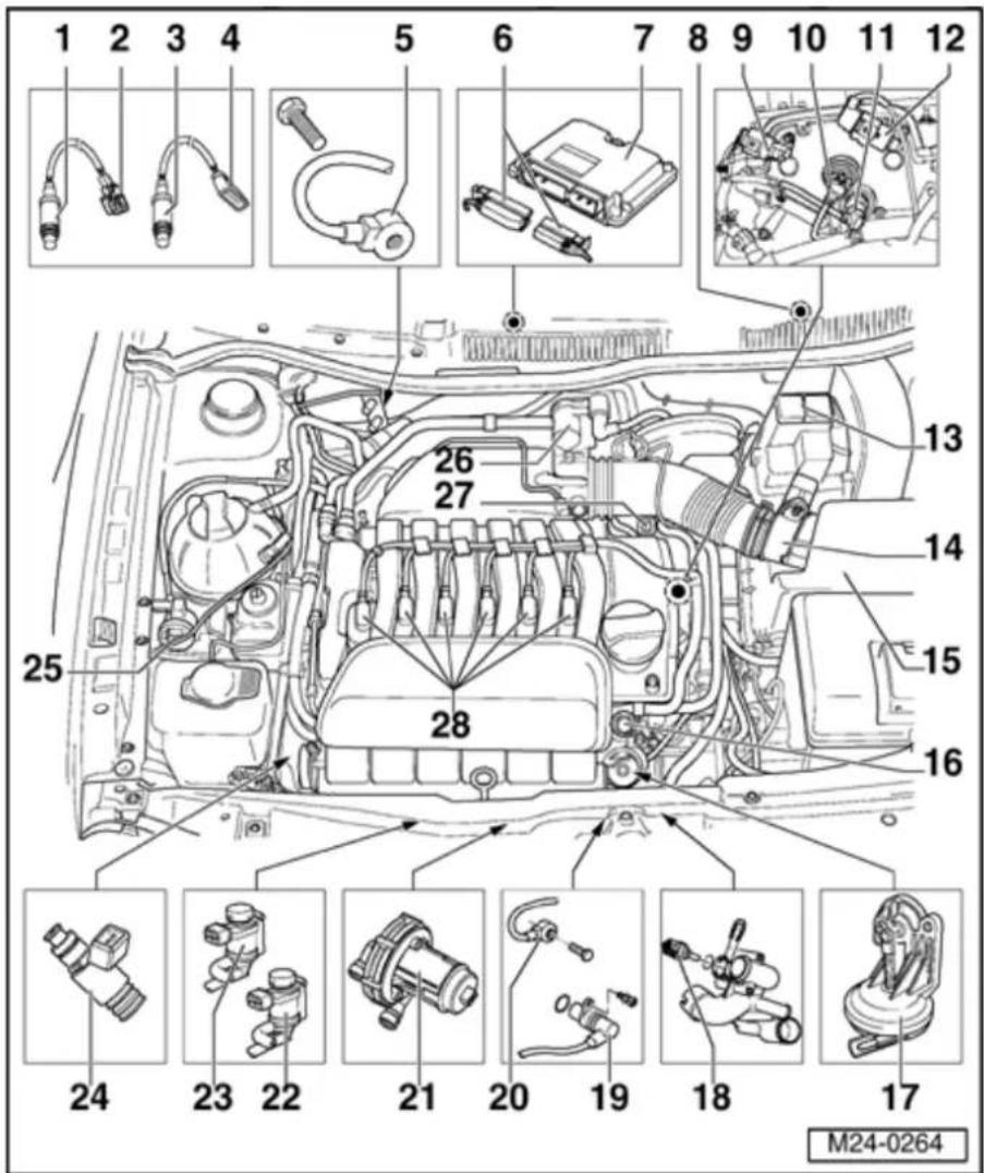
10 Valve -1-
- for camshaft adjustment -N205-
◆ For intake camshaft
Mark connector and component before pulling connector off.
◆ Checking activation ⇒ Page 01-100, Output Diagnosis Test Mode (DTM)
◆ Check camshaft timing adjustment:
→ Repair Manual, 2.8 Liter VR6 4V Engine Mechanical, Engine Code(s): BDF; Repair Group 15, Valve train, servicing
11 Camshaft
- Adjustment Valve 1 (exhaust) - N318-
◆ For exhaust camshaft
Mark connector and component before pulling connector off.
◆ Checking activation ⇒ Page 01-100, Output Diagnosis Test Mode (DTM)
◆ Check camshaft timing adjustment:
⇒ Repair Manual, 2.8 Liter VR6 4V Engine Mechanical, Engine Code(s): BDF; Repair Group 15, Valve train, servicing

12 - Camshaft Position (CMP) Sensor 2 - G163-
◆ For exhaust camshaft
◆ ⇒ Page 28-6, item 13
Mark connector and component before pulling connector off.
13 - Protective housing
♦ Relay assignment in protective housing ⇒ Fig. 1
14 Mass Air - Flow (MAF) sensor - G70- with Intake Air Temperature (IAT) sensor -G42-
15 - Air cleaner
16 - Fuel pressure regulator
17 - Vacuum actuator
◆ For Intake
Manifold
Change-
Over
Valve -
N156-
24-6
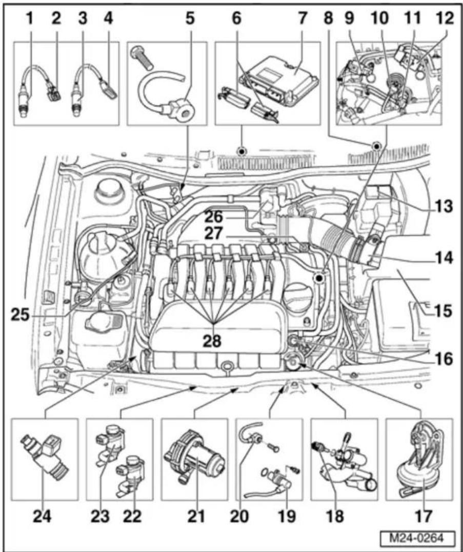
18 Engine
- Coolant Temperature (ECT) sensor - G62-
◆ For Motronic Engine Control Module (ECM) - J220-
◆ With Engine Coolant Temperature Gauge sensor -G2-
◆ Release pressure in cooling system if necessary before removing components
19 - Engine Speed (RPM) Sensor - G28-
20 - Knock Sensor (KS) 2 - G66-
◆ Component location: Between cyl. 4 and cyl. 6 ⇒ Page 28-8, item 17
21 - Secondary Air Injection
(AIR) Pump Motor - V101-
◆ Checking activation ⇒ Page 01-100, Output Diagnosis Test Mode (DTM)
◆ Secondary air system:
⇒ Repair Manual, 2.8 Liter VR6 4V Engine Mechanical, Engine Code(s): BDF; Repair Group 26

24-7
22 - Intake Manifold Change- Over Valve - N156-
23 Secondary - Air Injection (AIR) Solenoid Valve - N112-
◆ Checking activation → Page 01-100, Output Diagnosis Test Mode (DTM)
◆ Secondary air system:
⇒ Repair Manual, 2.8 Liter VR6 4V Engine Mechanical, Engine Code(s): BDF; Repair Group 26
24 - Fuel Fuel injector (-N30-...N33-, -N83-, -N84-)
25 Evaporative - Emission (EVAP) Canister Purge Regulator Valve -N80- ◆ Checking
activation
→ Page
01-100,
Output
Diagnosis
Test
Mode
(DTM)
◆ Evaporative
Emission
(EVAP)
Canister
system
⇒ Repair
Manual, 2.8
Liter VR6 4V
Engine
Mechanical,
Engine Code(s):
BDF; Repair
Group 20

24-8
26 - Throttle Valve Control Module -J338-
◆ Heated by coolant
27 - Combi-valve
◆ Secondary air system:
⇒ Repair Manual, 2.8 Liter VR6 4V Engine Mechanical, Engine Code (s): BDF; Repair Group 26
28 - Ignition coils with power output stage (-N70-, -N127-, -N291-, -N292-, -N323- and -N324-)
◆ ⇒ Page 28-3, item 2
24-9


Fig. 1 Relay assignment in protective housing (on left in engine compartment)
1 - Secondary Air Injection (AIR)
Pump Relay -J299-
2 - Motronic Engine Control Module (ECM) Power Supply Relay -J271-
Note:
If tools are necessary to pull relays or control modules out of the relay plate, first disconnect battery Ground (GND) strap.
Before disconnecting battery Ground (GND) strap obtain code for radios with anti-theft coding.
24-10
Fuel injection system, general notes
Servicing ignition parts:
⇒ Repair Manual, 2.8 Liter VR6 4V Engine Mechanical, Engine Code(s): BDF; Repair Group 28
Note:
The Motronic Engine Control Module (ECM) - J220- is equipped with On Board Diagnostic (OBD). Before carrying out repairs and troubleshooting the DTC memory must be checked. Also the vacuum hoses and connections must be checked (unmetered air).
◆ Fuel hoses in engine compartment must only be secured with spring-type clips. The use of clamp or screw-type clips is not permitted.
◆ Components marked with * are checked via On Board Diagnostic (OBD) ⇒ Page 01-23.
Components marked with **can be checked via Output Diagnosis Test Mode (DTM) ⇒ Page 01-100.
Do not use sealing compounds containing silicone. Particles of silicone drawn into the engine, will not be burned in the engine and may damage the Oxygen Sensor(s) (O2S).
For trouble-free operation of the electrical components, a voltage of at least 11.5 V is necessary.
♦ Disconnecting and connecting the battery must only be done with the ignition switched off, otherwise the Motronic Engine Control Module (ECM) -J220- could be damaged.
24-11
◆ Check DTC memory before carrying out repairs and when troubleshooting ⇒ Page 01-23, Checking and erasing DTC memory
During some checks it is possible that the control module will detect and store a Diagnostic Trouble Code (DTC). Therefore, after completing all checks and repairs the DTC memory must be checked and if necessary, erased Page 01-23Check and erasing DTC memory and then generate the readiness code Page 01-149.
If the engine starts, runs for a short period and then stops, after troubleshooting, repairs or component tests, then the Diagnostic Trouble Code (DTC) may lie with the Immobilizer which is blocking the Motronic Engine Control Module (ECM) -J220-. In such cases the DTC memory must be checked and, if necessary, the control module adapted.
⇒ Repair Manual, Electrical Equipment On Board Diagnostic (OBD); Repair Group 01
Safety precautions Page 24-33.
Rules for cleanliness Page 24-36.
Technical data Page 24-37.
Checking engine operating condition Page 24-158.
24-12

Fuel injection system components, removing and installing
1 - Secondary Air Injection (AIR) Solenoid Valve - N112-*/**
◆ Component location ⇒ Page 24-1, Component locations overview
◆ Valve will be activated by Motronic Engine Control Module (ECM) - J220-(pulsed)
◆ Secondary air system:
⇒ Repair Manual, 2.8 Liter VR6 4V Engine Mechanical, Engine Code (s): BDF; Repair Group 26
2 - Intake Manifold
Change-Over Valve - N156-*/**
◆ Component location ⇒ Page 24-1, Component locations overview
◆ Valve will be activated by Motronic Engine Control Module (ECM) - J220-(pulsed)
◆ Checking Intake Manifold Change- Over Valve - N156- ⇒ Page 24- 117
3 - Vacuum actuator
◆ For Intake Manifold Change- Over Valve - N156-
24-13

4 - Vacuum reservoir
◆ For Intake Manifold Change- Over Valve - N156-
◆ Removing and installing:
⇒ Repair Manual, 2.8 Liter VR6 4V Engine Mechanical, Engine Code(s): BDF; Repair Group 26
5 - Intake manifold
◆ Disassembling and assembling ⇒ Page 24-22
♦ Removing and installing: ⇒ Repair Manual, 2.8 Liter VR6 4V Engine Mechanical, Engine Code(s): BDF; Repair Group 15
6 - Throttle Valve Control Module - J338-\*
◆ Heated by coolant
Removing
and
installing
⇒ Page
24-22
24-14
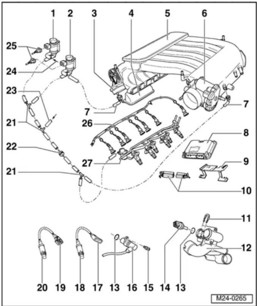
7 - Vacuum line
◆ Press together at front to release
8 - Motronic Engine Control Module (ECM) - J220-\*
(Motronic control module - J220-
◆ Component location: In plenum chamber
◆ Checking voltage supply ⇒ Page 24-163
◆ Procedure after interrupting voltage supply ⇒ Page 24-170
♦ Replacing ⇒ Page 24-173
♦ Coding ⇒ Page 24-177
When replacing, erase learned
values
and
adapt
Motronic
Engine
Control
Module
(ECM) -
J220- to
Throttle
Valve
Control
Module -
J338-
Page 24-
182
9 Supporting
- frame
24-15

10 - Connector
◆ For Motronic Engine Control Module (ECM) - J220-
◆ Disconnect or connect only with ignition switched off
◆ Release to disconnect
11 - Retaining clip
◆ Check seated securely
12 - Thermostat housing
◆ Component location ⇒ Page 24-1, Component locations overview
◆ Disassembling and assembling: ⇒ Repair Manual, 2.8 Liter VR6 4V Engine Mechanical, Engine Code(s): BDF; Repair Group 19
13 - O-ring
◆ Replace if damaged
24-16

14 Engine
- Coolant Temperature (ECT) sensor - G62-*
◆ For Motronic Engine Control Module (ECM) - J220-
◆ With Engine Coolant Temperature (ECT) sensor -G2-
◆ Gold plated terminals
◆ Release pressure in cooling system if necessary before removing components
◆ Checking ⇒ Page 24-69
15 - 10 Nm
16 - Engine Speed (RPM) Sensor - G28-*
◆ Component location ⇒ Page 24-1, Component locations overview
◆ Checking ⇒ Page 24-93
17 - Connector
◆ Black, 4-pin
◆ Terminals 3 and 4 are gold plated
◆ For Oxygen Sensor (O2S) Behind Three Way Catalytic Converter (TWC) - G130- and Oxygen Sensor (O2S) Heater 1 -Z29-
◆ Component location: Right on underside of vehicle
24-17

18 Oxygen - Sensor (O2S) Behind Three Way Catalytic Converter (TWC) - G130-*, 50 Nm
◆ Component location: In rear of Three Way Catalytic Converter
◆ Remove and install with ring wrench 3337
◆ Grease only threads with G 052 112 A3 hot bolt paste (anti-seize compound). Grease must not get into slots on sensor body
◆ If seal is leaking, replace seal.
♦ Oxygen Sensor (O2S) heating voltage
supply via fuel pump relay
Check Oxygen Sensor (O2S) heating for Oxygen Sensor (O2S) Behind Three Way Catalytic Converter (TWC) - G130- Page 24-45
Check Oxygen Sensor (O2S) and Oxygen Sensor control after Three Way Catalytic Converter (TWC) Page 24-140
◆ Check aging of Oxygen Sensor (O2S) Behind Three Way Catalytic Converter (TWC) - G130- ⇒ Page 24-
154
When replacing, erase learned values and adapt Motronic Engine Control Module (ECM) - J220- to Throttle Valve Control Module - J338- → Page 24-182
24-18

19 Connector
◆ Gold plated terminals
◆ Black, 6-pin
For Heated Oxygen Sensor (HO2S) -G39- and Oxygen Sensor (O2S) Heater -Z19-
◆ Component location: Right on underside of vehicle
24-19

20 - Heated Oxygen Sensor (HO2S) - G39-*, 50 Nm
◆ Component location: In front exhaust pipe
◆ Remove and install with Oxygen Sensor (O2S) ring wrench 3337
♦ Grease only threads with G 052 112 A3 hot bolt paste (ant-seize compound). Grease must not get into slots on sensor body
◆ If seal is leaking, remove and replace seal.
◆ Check Oxygen Sensor (O2S) heating
for Heated Oxygen Sensor (HO2S) ⇒ Page 24-38
Check Oxygen Sensor (O2S) and Oxygen Sensor control before Three Way Catalytic Converter (TWC) Page 24-131
◆ Check aging of Heated Oxygen Sensor (HO2S) → Page 24-150
When replacing, erase learned values and adapt Motronic Engine Control Module (ECM) - J220- to Throttle Valve Control Module -
J338- Page 24-182

24-20
21 - Junction piece
22 - Non-return valve
◆ Observe installation position
- White connector faces towards Secondary Air Injection (AIR) Solenoid Valve - N112-/Intake Manifold Change-Over Valve - N156-
23 - Vacuum line
◆ From vacuum reservoir: item 4
24 - From combi-valve
◆ Secondary air system:
⇒ Repair Manual, 2.8 Liter VR6 4V Engine Mechanical, Engine Code (s): BDF; Repair Group
26
25
Connector
◆ Black, 2-pin
Mark connector and component before pulling connector off.
24-21

26 - Wiring harness
◆ With connectors for fuel injectors
27 - Fuel rail
◆ Disassembling and assembling ⇒ Page 24-26
CAUTION!
Part numbers are for reference only. Always check with your Parts. Dept. for the latest parts information.
24-22

Intake manifold, disassembling and assembling
1 - Intake manifold
◆ Removing and installing:
⇒ Repair Manual, 2.8 Liter VR6 4V Engine Mechanical, Engine Code(s): BDF; Repair Group 15
2 - Seal
◆ Always replace
3 - Bearing cap
◆ For Intake Manifold Change-Over Valve - N156-barrel
4 - Bracket
◆ For engine cover mounting pin
5 - Mounting pin, 5 Nm
◆ For engine cover
6 - 5 Nm
24-23

7 - 23 Nm
8 - Vacuum unic
◆ From brake booster
9 - Vacuum unic
◆ From fuel system leal detectionpu
⇒ Repair Manual, 2 Liter VR6 4V Engin Mechanical, Engine Code(s): BDF; Rep Group 20
10 - Vacuum unic
◆ From fuel pressure regulator junction pie
11 - Vacuum unic
◆ From crankcase breather/Evapor Emission (EVAF Canister Purge RegulatorValve vacuum line jun piece
24-24

12 - Throttle Valve Control Module - J338-\*
◆ No cable cam plate for accelerator cable as this is an EPC system
◆ Checking ⇒ Page 24-59
When replacing, erase learned values and adapt Motronic Engine Control Module (ECM) - J220- to Throttle Valve Control Module - J338- ⇒ Page 24-182
◆ 6-pin connector
◆ Gold plated terminals
◆ Heated by coolant
13 - 8 Nm
14 - Vacuum line
◆ To Intake Manifold Change- Over Valve - N156- → Page 24-12, item 2
15 - Vacuum actuator
◆ For Intake Manifold Change- Over Valve - N156-
◆ Checking ⇒ Page 24-117
16 Positioning - lever
◆ For change-over barrel
◆ Check seated securely
24-25
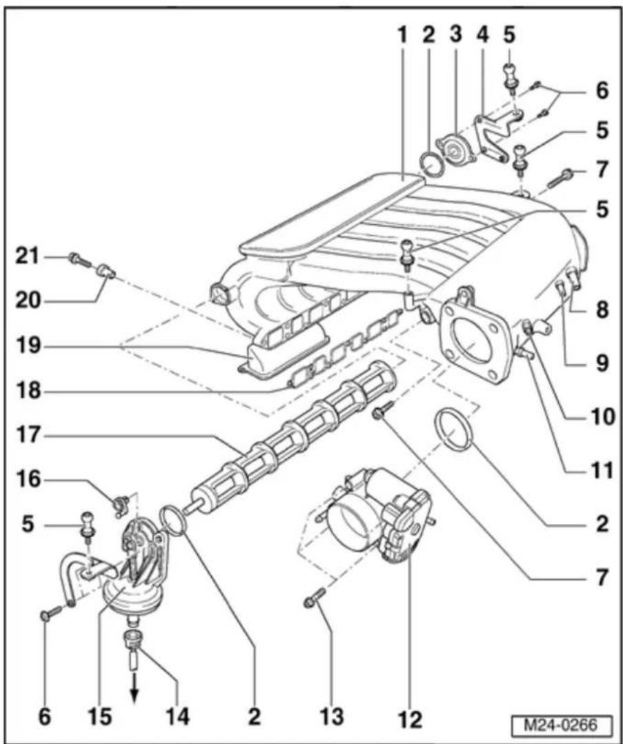
17 - Change-over barrel
18 - Gasket
◆ Observe installation position
♦ replace if damaged
19 Vacuum - reservoir
◆ For Intake Manifold Change- Over Valve - N156-
◆ Removing and installing:
⇒ Repair Manual, 2.8 Liter VR6 4V Engine Mechanical, Engine Code (s): BDF; Repair Group 26
20 - Dowel sleeve
◆ To secure intake manifold ◆ To locate gasket
21 - 13 Nm
24-26

Fuel rail, disassembling and assembling
1 - Fuel rail
2 - 8 Nm
3 - Return line
◆ Blue or with blue marking
◆ Secure with spring-type clips
◆ Check seated securely
◆ To fuel delivery unit:
⇒ Repair Manual, 2.8 Liter VR6 4V Engine Mechanical, Engine Code(s): BDF; Repair Group 20
4 - Supply line
Black
◆ Secure with spring-type clips
◆ Check seated securely
◆ From
fuel filter:
⇒ Repair Manual, 2.8 Liter VR6 4V Engine Mechanical, Engine Code(s): BDF; Repair Group 20
24-27

5 Connecting - hose
- Black
◆ Check seated securely
◆ Secure with spring-type clips
◆ For air shrouding of fuel injectors
◆ To intake hose ⇒ Page 24-30, item 5
6 - O-ring
♦ Replace
◆ Before installing moisten with clean engine oil
7 - Fuel injectors (-N30-...- N33-, - N83- and - N84-)*
Air shrouded
◆ Checking ⇒ Page
24-97
When
replacing,
erase
learned
values
and
adapt
Motronic
Engine
Control
Module
(ECM) -
J220- to
Throttle
Valve
Control
Module -
J338-
Page 24-
182
24-28
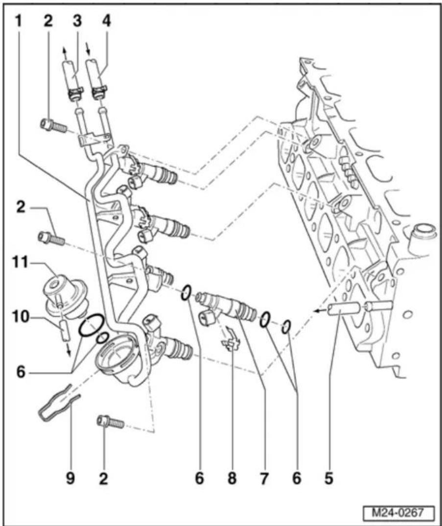
8 - Retaining clip
◆ Ensure seated correctly at fuel injector and fuel rail
9 - Retaining clip
◆ Check seated securely
10 - Vacuum line
◆ To non-return valve/intake manifold junction piece
11 - Fuel pressure regulator
◆ Checking ⇒ Page 24-110
24-29

Air cleaner assembly, disassembling and assembling
1 - Connecting hose
Black
◆ For crankcase breather
◆ Check seated securely
◆ Press together at front to release
◆ From breather housing on cylinder head cover
⇒ Repair Manual, 2.8 Liter VR6 4V Engine Mechanical, Engine Code(s): BDF: Repair Group 15
2 - O-ring
♦ Replace if damaged
3 - Positive Crankcase Ventilation (PCV) Heating Element -
N79-
◆ For crankcase breather
24-30
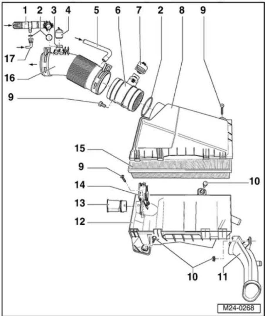
4 - Connector
◆ Black, 2-pin
◆ For Positive Crankcase Ventilation (PCV) Heating Element - N79-
◆ Check Positive Crankcase Ventilation (PCV) Heating Element - N79-voltage supply between terminals 1 and 2 with ignition switched on:
Specification: min. 11.5 V
5 - Connecting hose
Black
◆ Check seated securely
◆ For air shrouding of fuel injectors
◆ From connection on cylinder head ⇒
Page 24-27, item 5
6 Mass Air
- Flow (MAF) sensor - G70-* with Intake Air Temperature (IAT) sensor -G42-*
◆ Sensor and connector terminals are gold plated
◆ Check Mass Air Flow (MAF) sensor → Page 24-52
◆ Check Intake Air Temperature (IAT) sensor ⇒ Page 24- 81
24-31

7 - Connector
◆ Black, 5-pin
◆ Terminals from sensor and connector are gold plated
8 - Air cleaner upper part
9 - 6 Nm
10 - 10 Nm
11 Air intake - connecting piece
◆ For cold air intake
12 - Air cleaner lower part
13 Air intake - connecting piece
◆ For warm air intake
14 - Control flap
15 - Filter element
24-32

16 - Intake hose
◆ Check seat securely
◆ Secure with spring-type clips
◆ To Throttle Valve Cont Module -J3
17 - Vacuum line
◆ From intake manifold/Evapor Emissions (EVA canister purge regulator valve junction piece
◆ Press together at front to release
24-33
Safety precautions
CAUTION!
When performing repair work, especially to the confined conditions in the engine pay attention to the following:
Route all types of lines (e.g. for fuel, hydraulics, Evaporative Emissions (EV system, coolant, refrigerant, brake flui vacuum) as well as electrical wiring so the original positions are restored.
- Ensure sufficient clearance to all move hot components.
For safety reasons, fuse No. 28 must be removed from fuse holder before opening system because fuel pump can be activated door terminal switch in driver's door.
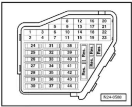
24-34
To prevent injuries to persons and/or damage to the fuel injection and ignition system, the following must be noted:
WARNING!
Fuel system is under pressure! Before opening the system place a cloth around the connection. Then release pressure by carefully loosening the connection.
Do not touch or disconnect ignition coils when the engine is running or being turned at starter speed.
◆ The ignition must be switched off before connecting or disconnecting injection or ignition system wiring or tester cables.
Observe following if test and measuring instruments are required during a road test:
◆ Test and measuring instruments must be secured to rear seat and operated by a 2nd person from this location.
WARNING!
If test and measuring instruments are operated from front passenger's seat and the vehicle is involved in an accident, there is a possibility that the person sitting in this seat may receive serious injuries when the airbag is triggered.
24-35


If the engine is to be turned at starter sp without starting:
- Remove fuse 29 (fuel pump) from fuse ho
Note:
Removing fuse 29 interrupts the voltage s u_i the fuel injectors.
- Remove engine cover.
- Disconnect connectors from ignition coils through 6.
Note:
Mark connector and component before disconnecting.
24-36
Rules for cleanliness
When working on the fuel supply/fuel injection system, pay careful attention to the following 5 Rules of Cleanliness:
- Thoroughly clean all unions and the adjacent areas before disconnecting.
◆ Place parts that have been removed on a clean surface and cover. Do not use fluffy cloths!
◆ Carefully cover opened components or seal, if the repair cannot be carried out immediately.
Only install clean components: Only unpack replacement parts immediately prior to installation. Do not use parts that have been stored loose (e.g. in tool boxes etc.).
When the system is open: Do not work with compressed air if this can be avoided. Do not move vehicle unless absolutely necessary.
24-37
Technical data
| Engine code | BDF | |
| Idling check | ||
| idle speed1) | rpm | 640 TO 7202) |
| Motronic Engine Control Module (ECM) -J220-3) | ||
| System designation | Motronic ME7.1.1⇒ Parts catalog | |
| Part number | ||
| Governed speed | rpm | from approx. 6500 |
1) idle speed check Page 24-125
2) Not adjustable
^3) Replacing Motronic Engine Control Module (ECM) -J220- Page 24-162
Components, checking
Heated Oxygen Sensor (HO2S), checking
Note:
◆ The vehicle must be raised to gain access. the Oxygen Sensor (O2S) connector.
Only gold plated terminals may be used repair the terminals in the Oxygen Sens (O2S) connectors.
Special tools and equipment
◆ VAG 1551 Scan tool (or VAG 1552) with 1551/3 adapter cable
Note:
All functions which could previously be performed with VAG 1551/1552 can also be performed by the VAS 5051.
◆ VAG 1526 or Fluke 83 Hand multimeter 1715 multimeter
◆ VAG 1594 Adapter set
◆ VAG 1598/31 Test box
Electrical Wiring Diagrams
24-39

Test requirements

• The fuses must be OK.
- The battery voltage must be at least 11.5 V.
- All electrical accessories, e.g. lights and rear window defroster must be switched off.
- If the vehicle is equipped with air conditioning, it must be switched off.
- Selector lever must be in position "P" or "N" on vehicles with an automatic transmission.
- Fuel Pump (FP) relay -J17- must be OK., checking:
⇒ Electrical Wiring Diagrams, Troubleshooting & Component Locations
24-40
Test sequence
- Connect VAG 1551 Scan tool (or VAG 1552) and select engine electronics control module with "Address word" 01. Engine must be running at idle speed: ((VAG 1551 and Motronic Engine Control Module (ECM) -J220-, connecting and selecting Page 01-12).
Rapid data transfer
HELP
Select function XX

Indicated on display:
- Press buttons -0- and -8- for function "Read measured value (data) block" and confirm entry with -Q- button.
Read measured value block

Indicated on display:
Input display group number XXX
- Press buttons -0-, -4- and -1- for "Display group number 41" and confirm entry with -Q- button.
Read measured value block 41

1 2 3 4

Indicated on display: (1...4 = display zones)
- Check status of the Oxygen Sensor (O2S) heating in display zone 2: Display: Htg.bC.ON / Htg.bC.OFF (alternating):
24-41
Note:
The Oxygen Sensor (O2S) heating may be switched on or off depending on the operational conditions of the engine, therefore the display zone 2 may show "Htg.bC.ON" or alternating from "Htg.bC.ON" to "Htg.bC.OF
- Press → b utton.
- Press buttons -0- and -6- for function "En output" and confirm entry with -Q- button.
- Switch off ignition.
If the display does not indicate as described
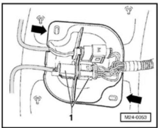
- Remove protective cover (arrows) and disconnect 6-pin connector (black) -1- to Oxygen Sensor (HO2S) -G39-.
24-42
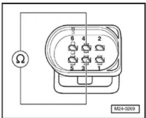
Checking resistance

- Check sensor heater wire resistance at connector terminals 3 and 4 to Oxygen Sensor (O2S). Specification: 2.5 to 10.0 Ω (at room temperature).
If the specification is not obtained:
- Replace Oxygen Sensor (O2S) 1, Bank 1 before Three Way Catalytic Converter (TWC) -G39-→ Page 24-19 , item 20 .
- Check DTC memory, repair malfunctions if necessary and then erase DTC memory Page 01-23.
- Erase learned values and adapt Motronic Engine Control Module (ECM) -J220- again Page 24-182.
- Read readiness code Page 01-146. If DTC memory has been erased or Motronic Engine Control Module (ECM) -J220- was disconnected from battery positive (B+), readiness code must be generated again Page 01-149.
If the specification is obtained:
24-43
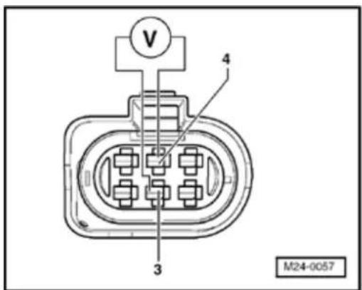
Checking voltage supply

- Connect multimeter to measure voltage at terminals 3 and 4 (connector to Motronic Engine Control Module (ECM) -J220-) using adapter cables from VAG 1594.
- Start engine and run at idle speed.
- M easure voltage supply and observe display group 41, display zone 2.
Display Htg.bC.ON: Specification: 11.0 to 14.5 V
Display Htg.bC.ON / Htg.bC.OFF (alternating): Specification: Between 0.0 to 12.0 V fluctuating
- Switch off ignition.
If no voltage is present:
- Remove wiper arms and cowl panel:
⇒ Repair Manual, Electrical Equipment; Repair Group 92

- Connect VAG 1598/31 test box to control module wiring harness. Engine Control Module (ECM) - J220- remains disconnected.
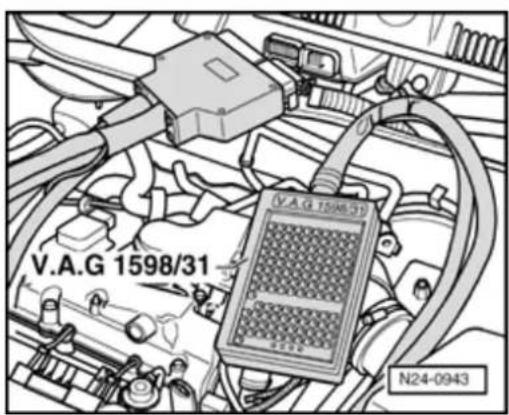
24-44
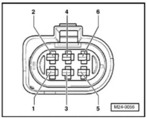

- Check wiring for open circuit between test box and 6-pin connector according to Electrical Wiring Diagrams. Terminal 4 and socket 5
Wire resistance: max. 1.5 Ω
If the specification is obtained:
- Check wire for open circuit between 6-pin connector terminal 3 and Fuel Pump (FP) -J17-referring to Electrical Wiring Diagrams.
Wire resistance: max. 1.5 Ω
If no wiring malfunction is detected:
- Replace Motronic Engine Control Module (ECM) -J220- Page 24-173.
- Check DTC memory, repair malfunctions if necessary and then erase DTC memory Page 01-23.
- Erase learned values and adapt Motronic Engine Control Module (ECM) -J220- again Page 24-182.
- Read readiness code Page 01-146. If DTC memory has been erased or Motronic Engine Control Module (ECM) -J220- was disconnected from battery positive (B+), readiness code must be generated again Page 01-149.
24-45
Oxygen Sensor (O2S) heating for Oxygen Sensor (O2S) Behind Three Catalytic Converter (TWC) -G130-, checking
Note:
◆ The vehicle must be raised to gain acce. the Oxygen Sensor (O2S) connector.
Only gold plated terminals may be used servicing Oxygen Sensor (O2S) connect terminals 3 and 4.
Special tools and equipment
◆ VAG 1551 Scan tool (or VAG 1552) with 1551/3 adapter cable
Note:
All functions which could previously be performed with VAG 1551/1552 can also be performed by the VAS 5051.
◆ VAG 1526 or Fluke 83 Hand multimeter 1715 multimeter
◆ VAG 1594 Adapter set
◆ VAG 1598/31 Test box
Electrical Wiring Diagrams


Test requirements

• The fuses must be OK.
- The battery voltage must be at least 11.5 V.
- All electrical accessories, e.g. lights and rear window defroster must be switched off.
- If the vehicle is equipped with air conditioning, this must be switched off.
- Selector lever must be in position "P" or "N" on vehicles with an automatic transmission.
- Fuel Pump (FP) relay -J17- must be OK., checking:
⇒ Electrical Wiring Diagrams, Troubleshooting & Component Locations
24-47
Test sequence
- Connect VAG 1551 Scan tool (or VAG 1552) and select engine electronics control module with "Address word" 01. Engine must be running at idle speed: ((VAG 1551 and Motronic Engine Control Module (ECM) -J220-, connecting and selecting Page 01-12).
Rapid data transfer
HELP
Select function XX

Indicated on display:
- Press buttons -0- and -8- for function "Read measured value (data) block" and confirm entry with -Q- button.
Read measured value block
Input display group number XXX

Indicated on display:
- Press buttons -0-, -4- and -1- for "Display group number 41" and confirm entry with -Q- button.
Read measured value block 41

1 2 3 4

Indicated on display: (1 to 4 = display zones)
- Check the status of the Oxygen Sensor (O2S) heating in display zone 4: Display: Htg.aC.ON / Htg.aC.OFF (alternating)
24-48
Note:
The Oxygen Sensor (O2S) heating may be switched on or off depending on the operational conditions of the engine, therefore the display zone 4 may show "Htg.aC.ON" or alternating from "Htg.aC.ON" to "Htg.aC.OF
- Press the → b utton.
- Press buttons -0- and -6- for function "En output" and confirm entry with the -Q- but
- Switch off ignition.
If the display does not indicate as described
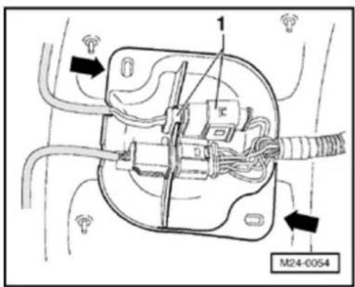
- Remove protective cover -arrows- and disconnect 4-pin connector (black) -1- to Sensor (O2S) Behind Three Way Catalytic Converter (TWC) -G130-.
24-49
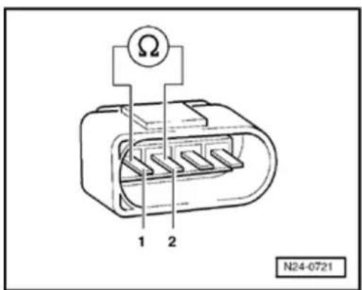
Checking resistance

- Check sensor heater wire resistance at connector terminals 1 and 2 to Oxygen Sensor (O2S).
- Specification: 6,4 to 47,5 Ω (at room temperature).
If the specification is not obtained:
- Replace Oxygen Sensor (O2S) 2, Bank 1 after Three Way Catalytic Converter (TWC) -G130- Page 24-17, item 18.
- Check DTC memory, repair malfunctions if necessary and then erase DTC memory Page 01-23.
- Erase learned values and adapt Motronic Engine Control Module (ECM) -J220- again Page 24-182.
- Read readiness code Page 01-146. If DTC memory has been erased or Motronic Engine Control Module (ECM) -J220- was disconnected from battery positive (B+), readiness code must be generated again Page 01-149.
If the specification is obtained:
24-50
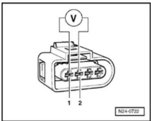
Checking voltage supply

- Connect multimeter to measure voltage at terminals 1 and 2 (connector to Motronic Engine Control Module (ECM) -J220-) using adapter cables from VAG 1594.
- Start engine and run at idle speed.
- M easure voltage supply and observe display group 41, display zone 4.
- Display Htg.aC.ON: Specification: 11.0 to 14.5 V
Display Htg.aC.ON / Htg.aC.OFF (alternating): Specification: Between 0.0 to 12.0 V fluctuating
- Switch off ignition.
If no voltage is present:
- Remove wiper arms and cowl panel:
⇒ Repair Manual, Electrical Equipment; Repair Group 92

- Connect VAG 1598/31 test box to control module wiring harness. Engine Control Module (ECM) - J220- remains disconnected.

24-51


- Check wiring for open circuit between test box and 4-pin connector referring to Electrical Wiring Diagrams.
Terminal 2 and socket 63
Wire resistance: max. 1.5 Ω
If the specification is obtained:
- Check wire for open circuit between 4-pin connector terminal 1 and Fuel Pump (FP) relay -J17-referring to Electrical Wiring Diagrams.
Wire resistance: max. 1.5 Ω
If no wiring malfunction is detected:
- Replace Motronic Engine Control Module (ECM) -J220- Page 24-173.
- Check DTC memory, repair malfunctions if necessary and then erase DTC memory Page 01-23.
- Erase learned values and adapt Motronic Engine Control Module (ECM) -J220- again Page 24-182.
- Read readiness code Page 01-146. If DTC memory has been erased or Motronic Engine Control Module (ECM) -J220- was disconnected from battery positive (B+), readiness code must be generated again Page 01-149.
24-52
Mass Air Flow (MAF) sensor - G70-, checking
Note:
Only gold plated terminals may be used to service terminals in the Mass Air Flow (MAF) sensor connector.
Special tools, materials and equipment
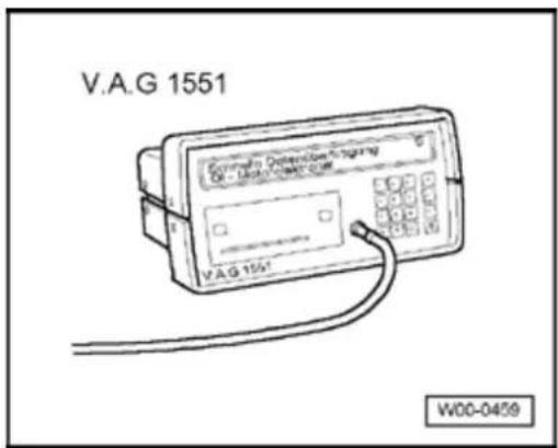

◆ VAG 1551 Scan tool (or VAG 1552) with VAG 1551/3 adapter cable
Note:
All functions which could previously be performed with VAG 1551/1552 can also be performed with the VAS 5051.
◆ VAG 1526 or Fluke 83 Hand
multimeter or VAG 1715
multimeter
◆ VAG 1594 Adapter set
◆ VAG 1598/31 Test box
Electrical Wiring Diagrams
24-53

Test requirements

• The fuses must be OK.
- The battery voltage must be at least 11.5 V.
- All electrical accessories, e.g. lights and rear window defroster must be switched off.
- If the vehicle is equipped with air conditioning, it must be turned off.
- Selector lever must be in position "P" or "N" on vehicles with an automatic transmission.
- Fuel Pump (FP) -J17- must be OK., checking:
⇒ Electrical Wiring Diagrams, Troubleshooting & Component Locations
- Coolant temperature must be at least 85 °C, ⇒d isplay group 1, display zone 2.
24-54
Test sequence
- Connect VAG 1551 Scan tool (or VAG 1552) and select engine electronics control module with "Address word" 01. Engine must be running at idle speed: ((VAG 1551 and Motronic Engine Control Module (ECM) -J220-, connecting and selecting Page 01-12).
Rapid data transfer
HELP
Select function XX

Indicated on display:
- Press buttons -0- and -8- for function "Read measured value (data) block" and confirm entry with -Q- button.
Read measured value block
Input display group number XXX

Indicated on display:
- Press buttons -0-, -0- and -2- for "Display group number 2" and confirm entry with -Q- button.
Read measured value block 2

1 2 3 4

Indicated on display: (1...4 = display zones)
- Check mass of air drawn in, in display zone 4 Specification: 3.0 to 5.0 g/s
- Press → b utton.
- Press buttons -0- and -6- for function "End output" and confirm entry with -Q- button.
24-55
- Switch off ignition.
If the specification is achieved but an Mass Flow (MAF) related Diagnostic Trouble Cod (DTC) is registered in Diagnostic Trouble C (DTC) memory:
- Check voltage supply for Mass Air Flow (sensor -G70- Page 24-55.
If the specification is not obtained:
- Check signal and Ground (GND) wires fo Air Flow (MAF) sensor -G70- Page 24
Checking voltage supply for Mass Air Flow (MAF) sensor
- Disconnect 5-pin connector from Mass Air (MAF) sensor -G70- with Intake Air Temp (IAT) sensor -G42- (arrow).
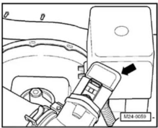
natural_image
Technical diagram of a vehicle's intake manifold and valve assembly (no text or symbols)24-56
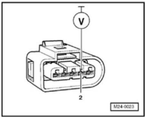
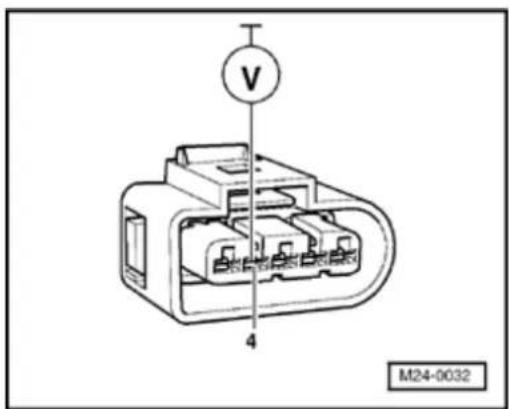

- Connect multimeter to measure voltage at connector terminal 2 and engine Ground (GND).
- Start engine and run at idle speed.
Specification: 11.0 to 15.0 V
- Switch off ignition.
If no voltage is present:
- Check wire for open circuit between 5-pin connector terminal 2 and Fuel Pump (FP) -J17-referring to Electrical Wiring Diagrams.
Wire resistance: max. 1.5 Ω
If the voltage supply and wiring is OK.:

- Connect multimeter to measure voltage at connector terminal 4 and engine Ground (GND).
- Switch on ignition
Specification: at least 4.5 V
- Switch off ignition.
24-57
If no voltage is present:
- Check signal and Ground (GND) wires fo Air Flow (MAF) sensor Page 24-57.
Checking signal and Ground (GND) wire: Mass Air Flow (MAF) sensor
- Remove wiper arms and cowl panel:
⇒ Repair Manual, Electrical Equipment; Re Group 92
- Connect VAG 1598/31 test box to control module wiring harness. Engine Control M (ECM) -J220- remains disconnected.

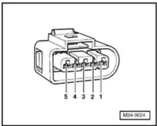


- Check wiring for open circuit between tes and 5-pin connector referring to Electrical Diagrams.
Terminal 3 and socket 27
Terminal 4 and socket 53
Terminal 5 and socket 29
Wire resistance: max. 1.5 Ω
24-58
- Additionally check wiring for short to one another, to vehicle Ground(GND) and to battery positive.
Specification: ∞ Ω
If no wiring malfunction is detected:
- Replace Mass Air Flow (MAF) sensor -G70- ⇒ Page 24-30, item 6.
- Check DTC memory, repair malfunctions if necessary and then erase DTC memory Page 01-23.
- Read readiness code Page 01-146. If DTC memory has been erased or Motronic Engine Control Module (ECM) -J220- was disconnected from battery positive (B+), readiness code must be generated again Page 01-149.
24-59
Throttle Valve Control Module -J338-, checking
Note:
Only gold plated terminals may be used to service the terminals in the connector of the Throttle valve control module -J338-.
Components of Throttle valve control module - J338-: Throttle drive (power accelerator actuation) -G186-, Angle sensor -1- for throttle drive (power accelerator actuation) -G187- and Angle sensor -2- for throttle drive (power accelerator actuation) -G188-.
Note:
If the Throttle valve control module -J338- is replaced, the new control module must be adapted to the Motronic Engine Control Module (ECM) -J220- Page 24-182.
◆ On vehicles installed with an automatic transmission the transmission control module must also be adapted:
⇒ Repair Manual, 4 Spd. Automatic Transmission 01M On Board Diagnostic (OBD); Repair Group 01
24-60

Special tools and equipment

◆ VAG 1551 Scan tool (or VAG 1552) with VAG 1551/3 adapter cable
Note:
All functions which could previously be performed with VAG 1551/1552 can also be performed with the VAS 5051.
◆ VAG 1526 or Fluke 83 Hand
multimeter or VAG 1715
multimeter
◆ VAG 1594 Adapter set
◆ VAG 1598/31 Test box
Electrical Wiring Diagrams
24-61

Test requirements

• The fuses must be OK.
- The battery voltage must be at least 11.5 V.
- All electrical accessories, e.g. lights and rear window defroster must be switched off.
- If the vehicle is equipped with air conditioning, it must be turned off.
- Selector lever must be in position "P" or "N" on vehicles with an automatic transmission.
- Fuel Pump (FP) Relay -J17-must be OK., checking:
⇒ Electrical Wiring Diagrams, Troubleshooting & Component Locations
- Engine Coolant Temperature (ECT) must be at least 85 °C, ⇒display group 1, display zone 2.
- Throttle valve not damaged or contaminated/dirty.
24-62
Test sequence
- Connect VAG 1551 Scan tool (or VAG 1552). Then switch ignition on and select Motronic Engine Control Module (ECM) -J220- with "Address word" 01. ((VAG 1551 and Motronic Engine Control Module (ECM) -J220-, connecting and selecting Page 01-12).
Rapid data transfer
HELP
Select function XX

Indicated on display:
- Press buttons -0- and -8- for function "Read measured value (data) block" and confirm entry with -Q- button.
Read measured value block
Input display group number XXX

Indicated on display:
- Press buttons -0-, -6- and -2- for "Display group number 62" and confirm entry with -Q- button.
Read measured value block 62

1 2 3 4

Indicated on display: (1 to 4 = display zones)
- Check throttle valve angle from Angle sensor -1-for throttle drive -G187- at idling stop in display zone 1
Specification: 3 to 93%
- Check throttle valve angle from Angle sensor -2-for throttle drive -G188- at idling stop in display zone 2
Specification: 97 to 3%
24-63
- Depress accelerator slowly to wide open throttle position and observe angles displayed in display zones 1 and 2:
Percentage display in display zone 1 must increase evenly. Full tolerance range 3 to 93% is not always displayed.
Percentage display in display zone 2 must drop evenly. Full tolerance range 97 to 3% is not always displayed.
Note:
The reason why the display in display zone 1 increases and the display in display zone 2 decreases is because the potentiometers (angle sensors) in the Throttle Valve Control Module -J338- run in opposite directions.
This means that the voltage of one angle sensor moves towards 5 volts. (The more the throttle valve is opened the higher the voltage; the percentage figure increases).
While the voltage of angle sensor 2 decreases from 5 volts towards 0 volts. (The more the throttle valve is opened the lower the voltage; the percentage figure decreases).
- Press → b utton.
- Press buttons -0- and -6- for function "End output" and confirm entry with -Q- button.
24-64

natural_image
Technical line drawing of a mechanical assembly with hoses and a black arrow indicating a specific component (no text or symbols present)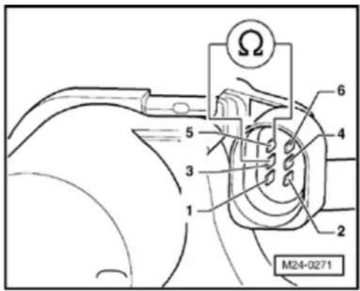
- Switch off ignition.
If the display does not indicate as described:

- Disconnect 6-pin connector from Throttle Valve Control Module - J338- (arrow).
Checking resistance

- M easure resistance from throttle valve drive between terminals 3 and 5
Specification: 1.0 to 5.0 Ω
If the specification is not obtained:
- Replace Throttle Valve Control Module -J338- Page 24-13, item 6.
- Check DTC memory, repair malfunctions if necessary and then erase DTC memory Page 01-23.
- Adapt Motronic Engine Control Module (ECM) -J220- to Throttle Valve Control Module -J338- → Page 24-182.
24-65
- Read readiness code Page 01-146. If DTC memory has been erased or Motronic Engine Control Module (ECM) -J220- was disconnected from battery positive (B+) , readiness code must be generated again Page 01-149.
If the specification is obtained:
- Check voltage supply of Throttle Valve Control Module -J338- and wiring to control module Page 24-66.
- Check Throttle Position (TP) sensor:
⇒ Repair Manual, 2.8 Liter VR6 4V Engine Mechanical, Engine Code(s): BDF; Repair Group 20
If the voltage supply and wiring are OK.:
- Replace Motronic Engine Control Module (ECM) -J220- Page 24-173.
- Check DTC memory, repair malfunctions if necessary and then erase DTC memory Page 01-23.
- Erase learned values and adapt Motronic Engine Control Module (ECM) -J220- again Page 24-182.
24-66
- Read readiness code Page 01-146f memory has been erased or Motronic En Control Module (ECM) -J220- was discor from battery positive (B+) , readiness code be generated again Page 01-149.
Checking voltage supply and wiring to control module
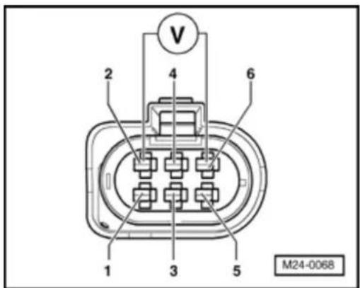

- Connect multimeter to measure voltage a connector terminals 2 (positive) and 6 (GND).
- Switch on ignition.
Specification: at least 4.5 V - Switch off ignition.
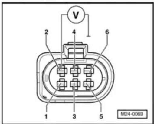

- Connect multimeter to measure voltage a connector terminal 2 (positive) and Grour (GND).
- Switch on ignition.
Specification: at least 4.5 V - Switch off ignition.
If the specifications are not obtained:
24-67

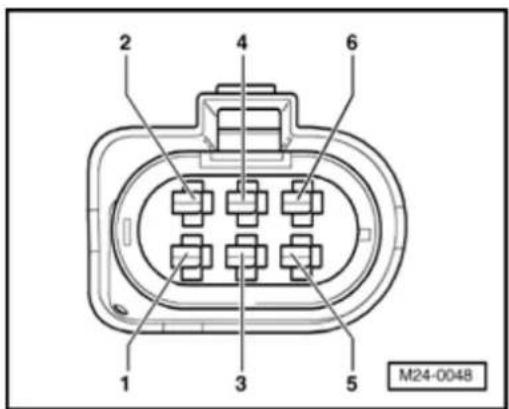
- Remove wiper arms and cowl panel:
⇒ Repair Manual, Electrical Equipment, Repair Group 92
- Connect VAG 1598/31 test box to control module wiring harness. Engine Control Module (ECM) - J220- remains disconnected.
- Check wiring for open circuit between test box socket and connector referring to Electrical Wiring Diagrams: Terminal 1 and socket 92 Terminal 2 and socket 83 Terminal 3 and socket 117 Terminal 4 and socket 84 Terminal 5 and socket 118 Terminal 6 and socket 91 Wire resistance: max. 1.5 Ω
24-68
- Additionally check wiring for short to one another, to vehicle Ground(GND) and to battery positive.
Specification: ∞ Ω
If no wiring malfunction is detected:
- Check Motronic Engine Control Module (ECM) - J220- voltage supply Page 24-163.
- Check DTC memory, repair malfunctions if necessary and then erase DTC memory Page 01-23.
- Read readiness code Page 01-146. If DTC memory has been erased or Motronic Engine Control Module (ECM) -J220- was disconnected from battery positive (B+), readiness code must be generated again Page 01-149.
24-69
Engine Coolant Temperature (ECT) sensors -G62- and -G2-, checking
Note:
The Motronic Engine Control Module (ECM) -J220- will use a replacement value for an engine start (start temperature replacement value) as soon as there is a Diagnostic Trouble Code (DTC) stored in the DTC memory, which affects the Engine Coolant Temperature (ECT) sensor -G62-. The temperature then rises according to a model stored in the control module. When the engine has reached normal working temperature a fixed replacement value will be displayed after a certain period.
24-70

Special tools and equipment

◆ VAG 1551 Scan tool (or VAG 1552) with VAG 1551/3 adapter cable
Note:
All functions which could previously be performed with VAG 1551/1552 can also be performed with the VAS 5051.
◆ VAG 1526 or Fluke 83 Hand
multimeter or VAG 1715
multimeter
◆ VAG 1594 Adapter set
◆ VAG 1598/31 Test box
Electrical Wiring Diagrams
Test requirements
- Selector lever must be in position "P" or "N" on vehicles with an automatic transmission.
• Engine must be cold.
24-71
Test sequence
Note:
Only gold plated terminals may be used when servicing the sensor connector terminals.
- Connect VAG 1551 Scan tool (or VAG 1552). Then switch ignition on and select Motronic Engine Control Module (ECM) -J220- with "Address word" 01. ((VAG 1551 and Motronic Engine Control Module (ECM) -J220-, connecting and selecting Page 01-12).
Rapid data transfer
HELP
Select function XX

Indicated on display:
- Press buttons -0- and -8- for function "Read measured value (data) block" and confirm entry with -Q- button.
Read measured value block
Input display group number XXX

Indicated on display:
- Press buttons -0-, -0- and -4- for "Display group number 4" and confirm entry with -Q- button.
Read measured value block 4

1 2 3 4

Indicated on display: (1 to 4 = display zones)
- Read coolant temperature value in display zone 3.
Specification: approx. coolant temperature
24-72
If the specification is not obtained:
- Check according to following table:
| Display^1) | Cause | Continuation of check |
| Approx. - 42.0 °C | Open circuit or short to positive | ⇒ Page 24-74 |
| Approx. 136.0 °C | Short to Ground (GND) | ⇒ Page 24-76 |
^1) If a temperature is displayed which deviates greatly from the ambient temperature of the sensor, check sensor wiring for transfer resistance.
If the specification is obtained:
- Start engine and run at idle speed. Temperature value must increase uniformly
Note:
If irregular engine running occurs in certain temperature ranges and the temperature figure does not increase without interruption, the temperature signal is temporarily interrupted and the sensor must be replaced.
24-73
- Press → b utton.
- Press buttons -0- and -6- for function "End output" and confirm entry with -Q- button.
- Switch off ignition.
If the display does not indicate as described:
- Replace Engine Coolant Temperature (ECT) sensor -G62-/Engine Coolant Temperature (ECT) sensor -G2- Page 24-16, item 14.
- Check DTC memory, repair malfunctions if necessary and then erase DTC memory Page 01-23.
- Read readiness code Page 01-146. If DTC memory has been erased or Motronic Engine Control Module (ECM) -J220- was disconnected from battery positive (B+), readiness code must be generated again Page 01-149.
24-74
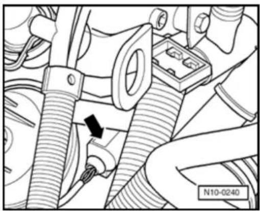
natural_image
Mechanical assembly diagram showing hoses and components with a black arrow indicating a specific connection point (no text or symbols present)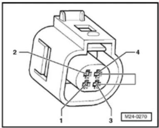
Continuation of check when display reads approx. -42.0 °C

- Disconnect 4-pin connector (arrow( from Engine Coolant Temperature (ECT) sensor -G62-/Engine Coolant Temperature (ECT) sensor -G2-.

- Jumper connector terminals 3 and 4 using adapter cables from VAG 1594 and observe display.
If display jumps to approx. 136.0 °C:
- Press → b utton.
- Press buttons -0- and -6- for function "End output" and confirm entry with -Q- button.
- Switch off ignition.
24-75
- Replace Engine Coolant Temperature (ECT) sensor -G62- / Engine Coolant Temperature (ECT) sensor -G2- ⇒ Page 24-16, item 14.
- Check DTC memory, repair malfunctions if necessary and then erase DTC memory Page 01-23.
- Read readiness code Page 01-146. If DTC memory has been erased or Motronic Engine Control Module (ECM) -J220- was disconnected from battery positive (B+), readiness code must be generated again Page 01-149.
If display remains at approx. -42.0 °C:
- Press → b utton.
- Press buttons -0- and -6- for function "End output" and confirm entry with -Q- button.
- Switch off ignition.
- Check wiring referring to Electrical Wiring Diagrams Page 24-77.
24-76

natural_image
Mechanical assembly diagram showing hoses and components with a black arrow indicating a specific connection point (no text or symbols present)Continuation of check when display reads approx. 136.0 °C

- Disconnect 4-pin connector (arrow) from Engine Coolant Temperature (ECT) sensor -G62-/Engine Coolant Temperature (ECT) sensor -G2-.
If display jumps to approx. -42.0 °C:
- Press → b utton.
- Press buttons -0- and -6- for function "End output" and confirm entry with -Q- button.
- Switch off ignition.
- Replace Engine Coolant Temperature (ECT) sensor -G62-/Engine Coolant Temperature (ECT) sensor -G2- Page 24-16, item 14.
- Check DTC memory, repair malfunctions if necessary and then erase DTC memory Page 01-23.
- Read readiness code Page 01-146. If DTC memory has been erased or the Motronic Engine Control Module (ECM) -J220- was disconnected from battery positive (B+), readiness code must be generated again Page 01-149.
24-77
If display remains at approx. 136.0 °C:
- Press → b utton.
- Press buttons -0- and -6- for function "En output" and confirm entry with -Q- button.
- Switch off ignition.
- Check wiring referring to Electrical Wiring Diagrams Page 24-77.
Checking wiring
- Remove wiper arms and cowl panel:
⇒ Repair Manual, Electrical Equipment; Re Group 92
- Connect VAG 1598/31 test box to control module wiring harness. Engine Control M (ECM) -J220- remains disconnected.

24-78
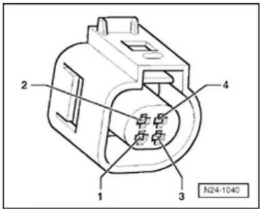
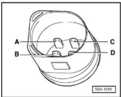

- Check wiring for open circuit between test box and 4-pin connector referring to Electrical Wiring Diagrams.
Terminal 3 and socket 93
Terminal 4 and socket 108
Wire resistance: max. 1.5 Ω
- Additionally check wiring for short to one another, to vehicle Ground (GND) and to battery positive.
Specification:
If no wiring malfunction is detected:

- Perform resistance measurement on Engine Coolant Temperature (ECT) sensor -G62- terminal C (signal) and D (Ground).
24-79
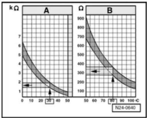
line
| Panel | Temperature (°C) | Resistance (kΩ) | |-------|------------------|-----------------| | A | 0 | 6 | | A | 10 | 4 | | A | 20 | 3 | | A | 30 | 2 | | A | 40 | 1.5 | | A | 50 | 1 | | B | 50 | 900 | | B | 60 | 700 | | B | 70 | 500 | | B | 80 | 300 | | B | 90 | 200 | | B | 100 | 150 |Scale A shows resistance values for temperature range 0 to 50 °C and scale B the values for temperature range 50 to 100 °C.
Examples:
◆ 30 °C is in range A and corresponds to a resistance of 1.5 to 2.0 kΩ
♦ 80 °C is in range B and corresponds to a resistance of 275 to 375 Ω
If the specification is not obtained:
- Replace Engine Coolant Temperature (ECT) sensor -G62-/Engine Coolant Temperature (ECT) sensor -G2- ⇒ Page 24-16, item 14.
- Check DTC memory, repair malfunctions if necessary and then erase DTC memory Page 01-23.
- Read readiness code Page 01-146. If DTC memory has been erased or Motronic Engine Control Module (ECM) -J220- was disconnected from battery positive (B+), readiness code must be generated again Page 01-149.
24-80
If there is no Diagnostic Trouble Code (DTC) in the wiring and the resistance measurement values are OK.:
- Replace Motronic Engine Control Module (ECM) -J220- Page 24-173.
- Check DTC memory, repair malfunctions if necessary and then erase DTC memory Page 01-23.
- Erase learned values and adapt Motronic Engine Control Module (ECM) -J220- again Page 24-182.
- Read readiness code Page 01-146. If DTC memory has been erased or Motronic Engine Control Module (ECM) -J220- was disconnected from battery positive (B+), readiness code must be generated again Page 01-149.
24-81
Intake Air Temperature (IAT) sensor -G42-, checking
Note:
The Intake Air Temperature (IAT) sensor -G42- is a component part of the Mass Air Flow (MAF) sensor -G70- and cannot be replaced individually.
24-82

Special tools, materials and equipment

◆ VAG 1551 Scan tool (or VAG 1552) with VAG 1551/3 adapter cable
Note:
All functions which could previously be performed with VAG 1551/1552 can also be performed with the VAS 5051.
◆ VAG 1526 or Fluke 83 Hand
multimeter or VAG 1715
multimeter
◆ VAG 1594 Adapter set
◆ VAG 1598/31 test box
◆ VAS 5024 Assembly tool for spring-type clips
Electrical Wiring Diagrams
◆ Chilling spray (commercially available)
Test requirements
- Selector lever must be in position "P" or "N" on vehicles with an automatic transmission.
24-83
Test sequence
Note:
Only gold plated terminals may be used to service the terminals in the Intake Air Temperature (IAT) sensor.
- Connect VAG 1551 Scan tool (or VAG 1552). Then switch ignition on and select Motronic Engine Control Module (ECM) -J220- with "Address word" 01. ((VAG 1551 and Motronic Engine Control Module (ECM) -J220-, connecting and selecting Page 01-12).
Rapid data transfer
HELP
Select function XX

Indicated on display:
- Press buttons -0- and -8- for function "Read measured value (data) block" and confirm entry with -Q- button.
Read measured value block
Input display group number XXX

Indicated on display:
- Press buttons -0-, -0- and -4- for "Display group number 4" and confirm entry with -Q- button.
Read measured value block 4

1 2 3 4

Indicated on display: (1 to 4 = display zones)
- Read intake air temperature value in display zone 4.
Specification: approx. ambient temperature
24-84
If the specification is not obtained:
- Check according to following table:
| Display^1) | Cause | Continuation of check |
| Approx. - 37.0 °C | Open circuit or short to positive | ⇒ Page 24-86 |
| Approx. 126.0 °C | Short to Ground (GND) | ⇒ Page 24-88 |
^1) If a temperature is displayed which is below the ambient air temperature of the sensor, check sensor wiring for transfer resistance. Note when doing this that sensor may be heated from external sources, e.g. radiated heat when engine is not running.
If the specification is obtained:
- Remove intake hose between Mass Air Flow (MAF) sensor and Throttle Valve Control Module -J338- (⇒ Page 24-32, item 16) using VAS 5024 assembly tool for spring-type clips.
- Note intake air temperature value in display zone 4.
24-85
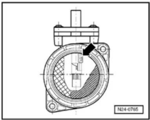

- Spray sensor (arrow) with commercial chilling agent while observing temperature value. Temperature value must decrease.
- Press → b utton.
- Press buttons -0- and -6- for function "End output" and confirm entry with -Q- button.
- Switch off ignition.
- Replace Mass Air Flow (MAF) sensor -G70- Page 24-30, item 6.
- Check DTC memory, repair malfunctions if necessary and then erase DTC memory Page 01-23.
- Read readiness code Page 01-146. If DTC memory has been erased or Motronic Engine Control Module (ECM) -J220- was disconnected from battery positive (B+), readiness code must be generated again Page 01-149.
24-86
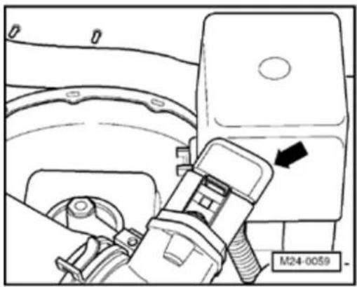
natural_image
Technical diagram of a vehicle's engine compartment with a directional arrow and label M24-0059 (no readable text or symbols beyond labels)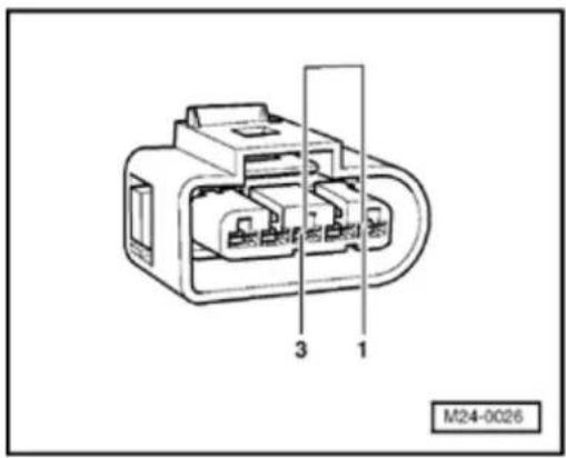
Continuation of check when display reads approx. -37.0 °C

- Disconnect 5-pin connector (arrow) from Mass Air Flow (MAF) sensor -G70- with Intake Air Temperature (IAT) sensor -G42-.

- Jumper connector terminals 1 and 3 using adapter cables from VAG 1594 and observe display.
If display jumps to approx. 126.0 °C:
- Press → b utton.
- Press buttons -0- and -6- for function "End output" and confirm entry with -Q- button.
- Switch off ignition.
24-87
- Replace Mass Air Flow (MAF) sensor -G70- ⇒ Page 24-30, item 6.
- Check DTC memory, repair malfunctions if necessary and then erase DTC memory Page 01-23.
- Read readiness code Page 01-146. If DTC memory has been erased or Motronic Engine Control Module (ECM) -J220- was disconnected from battery positive (B+), readiness code must be generated again Page 01-149.
If display remains at approx. -37.0 °C:
- Press → b utton.
- Press buttons -0- and -6- for function "End output" and confirm entry with -Q- button.
- Switch off ignition.
- Check wiring referring to Electrical Wiring Diagrams Page 24-89.
24-88

natural_image
Technical diagram of a vehicle's engine compartment with a directional arrow and label M24-0059 (no readable text or symbols beyond labels)Continuation of check when display reads approx. 126.0 °C

- Disconnect 5-pin connector (arrow) from Mass Air Flow (MAF) sensor -G70- with Intake Air Temperature (IAT) sensor -G42-.
If display jumps to approx. -42.0 °C:
- Press → b utton.
- Press buttons -0- and -6- for function "End output" and confirm entry with -Q- button.
- Switch off ignition.
- Replace Mass Air Flow (MAF) sensor -G70- ⇒ Page 24-30, item 6.
- Check DTC memory, repair malfunctions if necessary and then erase DTC memory Page 01-23.
- Read readiness code Page 01-146. If DTC memory has been erased or Motronic Engine Control Module (ECM) -J220- was disconnected from battery positive (B+), readiness code must be generated again Page 01-149.
24-89
If display remains at approx. 126.0 °C:
- Press → b utton.
- Press buttons -0- and -6- for function "En output" and confirm entry with -Q- button.
- Switch off ignition.
- Check wiring referring to Electrical Wiring Diagrams Page 24-89.
Checking wiring
- Remove wiper arms and cowl panel:
⇒ Repair Manual, Electrical Equipment; Re Group 92
- Connect VAG 1598/31 test box to control module wiring harness. Engine Control M (ECM) -J220- remains disconnected.

24-90
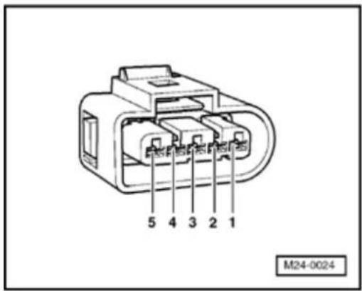
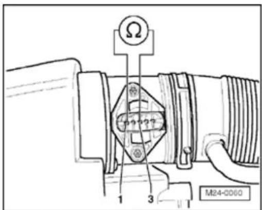

- Check wiring for open circuit between test box and 5-pin connector referring to Electrical Wiring Diagrams.
Terminal 1 and socket 26
Terminal 3 and socket 27
Wire resistance: max. 1.5 Ω
- Additionally check wiring for short to one another, to vehicle Ground (GND) and to battery positive.
Specification:
If no wiring malfunction is detected:

- Perform a resistance measurement on Intake Air Temperature (IAT) sensor -G42-terminals 1 (signal) and 3 (Ground).
24-91

line
| Panel | Temperature (°C) | Resistance (kΩ) | |-------|------------------|-----------------| | A | 0 | 7 | | A | 10 | 5 | | A | 20 | 3 | | A | 30 | 2 | | A | 40 | 1.5 | | A | 50 | 1 | | B | 50 | 900 | | B | 60 | 700 | | B | 70 | 500 | | B | 80 | 300 | | B | 90 | 200 | | B | 100 | 150 |Scale A shows resistance values for temperature range 0 to 50 °C and scale B the values for temperature range 50 to 100 °C.
Examples:
◆ 30 °C is in range A and corresponds to a resistance of 1.5 to 2.0 kΩ
♦ 80 °C is in range B and corresponds to a resistance of 275 to 375 Ω
If the specification is not obtained:
- Replace Mass Air Flow (MAF) sensor -G70- Page 24-30, item 6.
- Check DTC memory, repair malfunctions if necessary and then erase DTC memory Page 01-23.
- Read readiness code Page 01-146. If DTC memory has been erased or Motronic Engine Control Module (ECM) -J220- was disconnected from battery positive (B+), readiness code must be generated again Page 01-149.
24-92
If there is no Diagnostic Trouble Code (DTC) in the wiring and the resistance measurement values are OK.:
- Replace Motronic Engine Control Module (ECM) -J220- Page 24-173.
- Check DTC memory, repair malfunctions if necessary and then erase DTC memory Page 01-23.
- Erase learned values and adapt Motronic Engine Control Module (ECM) -J220- again Page 24-182.
- Read readiness code Page 01-146. If DTC memory has been erased or Motronic Engine Control Module (ECM) -J220- was disconnected from battery positive (B+), readiness code must be generated again Page 01-149.
24-93
Engine Speed (RPM) Sensor -G28-, checking
Function
The Engine Speed (RPM) Sensor -G28- is a speed and reference mark sensor. The engine will not start if there is no speed signal. If the speed signal fails when the engine is running will cause the engine to stall immediately.
Special tools, materials and equipment
◆ VAG 1526 or Fluke 83 Hand multimeter 1715 multimeter
◆ VAG 1594 Adapter set
◆ VAG 1598/31 test box
Electrical Wiring Diagrams
Test sequence
- Separate gray 3-pin connector (arrow) to Speed (RPM) Sensor.
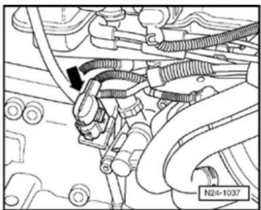
natural_image
Mechanical assembly diagram showing engine components and wiring (no text or labels)24-94
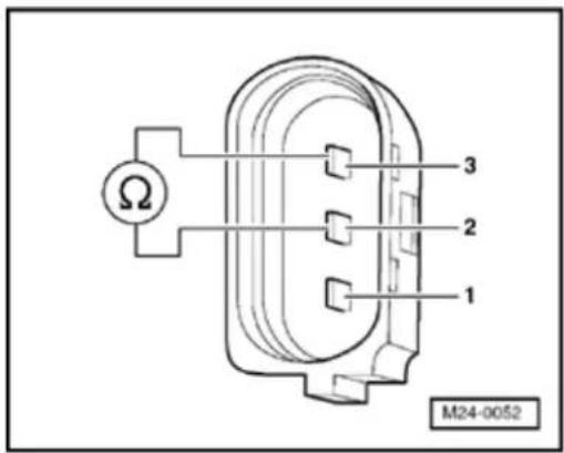

- M easure sensor resistance between connector terminals 2 and 3 to sensor.
Specification: 480 to 1000 Ω
- Check sensor for short circuit between terminals 1 and 2 as well as 1 and 3.
Specification:
If the specifications are not obtained:
- Replace Engine Speed (RPM) Sensor -G28- Page 24-16, item 16.
- Check DTC memory, repair malfunctions if necessary and then erase DTC memory Page 01-23.
- Read readiness code Page 01-146. If DTC memory has been erased or Motronic Engine Control Module (ECM) -J220- was disconnected from battery positive (B+), readiness code must be generated again Page 01-149.
If no sensor Diagnostic Trouble Code (DTC) is detected:
- Remove wiper arms and cowl panel:
⇒ Repair Manual, Electrical Equipment; Repair Group 92
24-95

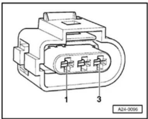
- Connect VAG 1598/31 test box to control module wiring harness. Engine Control Module (ECM) - J220- remains disconnected.
- Check wiring for open circuit between test box and 3-pin connector referring to Electrical Wiring Diagrams.
Terminal 1 and socket 108
Terminal 2 and socket 90
Terminal 3 and socket 82
Wire resistance: max. 1.5 Ω
- Additionally check wiring for short to one another, to vehicle Ground (GND) and to battery positive.
Specification:
24-96
If no wiring malfunction is detected:
- Remove sensor and check sensor wheel for secure mounting, damage and run-out.
Note:
There is a larger gap on the sensor wheel. This gap is the reference mark and does not mean that the sensor wheel is damaged.
If no Diagnostic Trouble Code (DTC) is detected on sensor wheel:
- Replace Motronic Engine Control Module (ECM) -J220- Page 24-173.
- Check DTC memory, repair malfunctions if necessary and then erase DTC memory Page 01-23.
- Erase learned values and adapt Motronic Engine Control Module (ECM) -J220- again Page 24-182.
- Read readiness code Page 01-146. If DTC memory has been erased or Motronic Engine Control Module (ECM) -J220- was disconnected from battery positive (B+), readiness code must be generated again Page 01-149.
24-97
Fuel injectors, checking
Special tools, materials and equipment
◆ VAG 1526 or Fluke 83 Hand multimeter 1715 multimeter
◆ VAG 1527 LED test light
◆ VAG 1594 Adapter set
◆ VAG 1598/31 test box
Electrical Wiring Diagrams
Test requirements
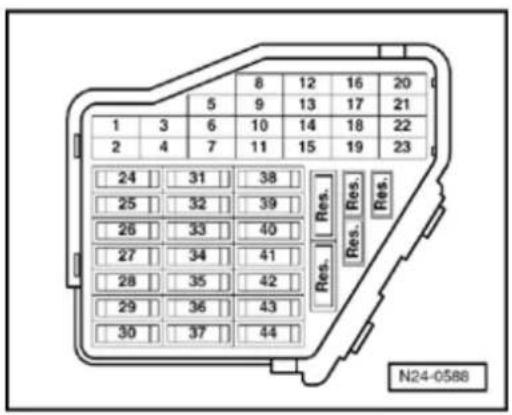

• The fuses must be OK.
• The battery voltage must be at least 11.
- All electrical accessories, e.g. lights and window defroster must be switched off.
- If the vehicle is equipped with air condition, it must be turned off.
- Selector lever must be in position "P" or vehicles with an automatic transmission
24-98
- Fuel Pump (FP) Relay -J17- must be OK., checking:
⇒ Electrical Wiring Diagrams, Troubleshooting & Component Locations
Checking activation
- First check activation of fuel injectors via Output Diagnosis Test Mode (DTM) Page 01-100.
If activation is OK:
- Remove intake manifold:
⇒ Repair Manual, 2.8 Liter VR6 4V Engine Mechanical, Engine Code(s): BDF; Repair Group 15
Note:
Seal the intake ports in the intake manifold or in the cylinder head with a clean cloth.
- Pull connector off all fuel injectors.
24-99
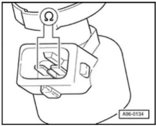
natural_image
Line drawing of a hand holding a mechanical component with a circular head and a labeled section A96-0134 (no text or symbols on the diagram itself)Checking resistance of fuel injectors

- Check resistance of fuel injectors between terminals.
Specification: 13.0 to 19.0 Ω
Note:
The resistance value is valid when measured at approx. 20 °C. The resistance value increases at higher temperatures.
If the specification is not obtained:
- Replace faulty fuel injector Page 24-27, item 7.
Observe the following when installing fuel injectors:
◆ Replace O-rings on all fuel injectors and moisten them lightly with clean engine oil.
◆ Insert fuel injectors vertically and in the correct position into the fuel rail and secure with retaining clips.
◆ Set fuel rail with secured fuel injectors on cylinder head and press in evenly.
◆ The connectors must audibly engage in the fuel injectors when pushed on.
24-100
- Check DTC memory, repair malfunctions necessary and then erase DTC memory 01-23.
- Erase learned values and adapt Motronic Engine Control Module (ECM) -J220-aga Page 24-182.
- Read readiness code Page 01-146. If memory has been erased or Motronic En Control Module (ECM) -J220- was discor from battery positive (B+), readiness code be generated again Page 01-149.
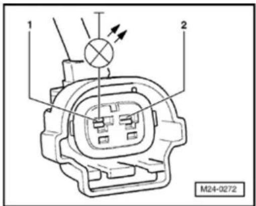
Checking voltage supply
- Connect VAG 1527 LED test light to term and Ground (GND) of relevant fuel injector connector using adapter cables from VAG
- Operate starter and check voltage supply fuel injector.
LED must light up - Switch off ignition.
If the LED does not light up:
- Check wire for open circuit between 2-pir connector terminal 1 and Fuel Pump (FP) -J17- referring to Electrical Wiring Diagram
Wire resistance: max. 1.5 Ω
24-101
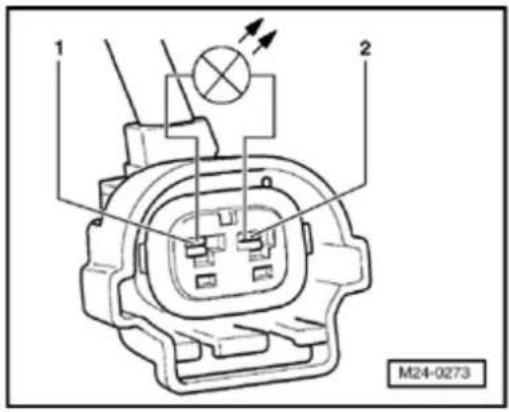

Checking activation and voltage supply

- Connect VAG 1527 LED test light to connector terminals of fuel injector to be tested using cables from VAG 1594.
- Operate starter and check activation for fuel injector.
LED must flicker
- Switch off ignition.
The LED does not flicker:
- Remove wiper arms and cowl panel:
⇒ Repair Manual, Electrical Equipment; Repair Group 92

- Connect VAG 1598/31 test box to control module wiring harness. Engine Control Module (ECM) - J220- remains disconnected.
24-102
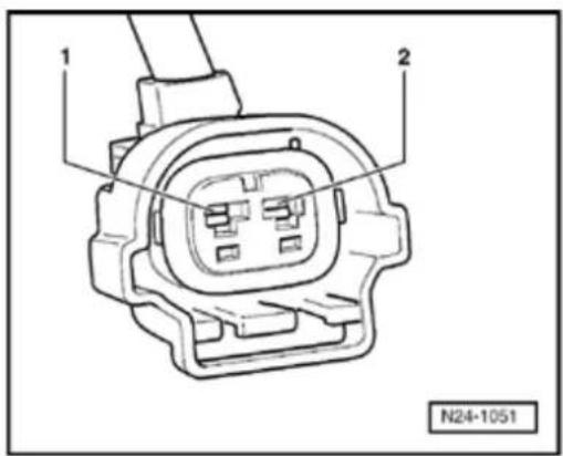

- Check wiring for open circuit between test box and the 2-pin connector for fuel injectors referring to Electrical Wiring Diagrams.
Fuel injector 1: Terminal 2 and socket 96
Fuel injector 2: Terminal 2 and socket 112
Fuel injector 3: Terminal 2 and socket 88
Fuel injector 4: Terminal 2 and socket 113
Fuel injector 5: Terminal 2 and socket 97
Fuel injector 6: Terminal 2 and socket 89
Wire resistance: max. 1.5 Ω
- Additionally check wiring for short to one another, to vehicle Ground (GND) and to battery positive.
Specification:
24-103
If there is no Diagnostic Trouble Code (DTC) in the wiring and the resistance measurement values are OK.:
- Replace Motronic Engine Control Module (ECM) -J220- Page 24-173.
- Check DTC memory, repair malfunctions if necessary and then erase DTC memory Page 01-23.
- Erase learned values and adapt Motronic Engine Control Module (ECM) -J220- again Page 24-182.
- Read readiness code Page 01-146. If DTC memory has been erased or Motronic Engine Control Module (ECM) -J220- was disconnected from battery positive (B+), readiness code must be generated again Page 01-149.
24-104
V.A.G 1348/3 | V.A.G 1348/3-2 |
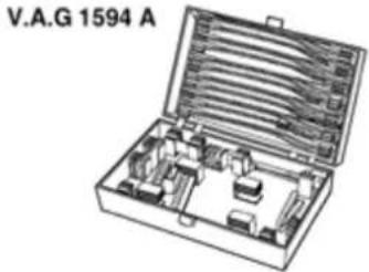 | V.A.G 1598/31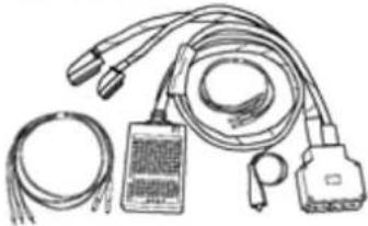 |
V.A.G 1602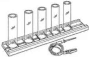 |
Fuel injectors, checking for leaks and quantity injected
Special tools and equipment
◆ VAG 1348/3 Remote control
◆ VAG 1348/3-2 Adapter
◆ VAG 1594 A Adapter set
◆ VAG 1598/31 Test box
◆ VAG 1602 Calibration tester
24-105
Test requirements
- The fuel pressure must be in order, checking Page 24-110.
Test sequence
- Remove intake manifold:
⇒ Repair Manual, 2.8 Liter VR6 4V Engine Mechanical, Engine Code(s): BDF; Repair Group 15 - Remove fuel rail complete (fuel lines remain connected) Page 24-26.
Checking for leaks
- Initiate output Diagnosis Test Mode (DTM) Page 01-100;
Fuel pump must run.
Note:
This work sequence allows the fuel pump to run when the engine is not running.
- Check fuel injector for leaks (visual check).
Only 1 to 2 drops per minute must emit from each fuel injector when fuel pump is running.
- Switch off ignition.
24-106
If the fuel loss is greater:
- Replace faulty fuel injector Page 24-27, item 7.
Observe the following when installing fuel injectors:
◆ Replace O-rings on all fuel injectors and moisten them lightly with clean engine oil.
◆ Insert fuel injectors vertically and in the correct position into the fuel rail and secure with retaining clips.
◆ Set fuel rail with secured fuel injectors on cylinder head and press in evenly.
◆ The connectors must audibly engage in the fuel injectors when pushed on.
- Check DTC memory, repair malfunctions if necessary and then erase DTC memory Page 01-23.
- Erase learned values and adapt Motronic Engine Control Module (ECM) -J220- again Page 24-182.
24-107
- Read readiness code Page 01-146f memory has been erased or Motronic En Control Module (ECM) -J220- was discor from battery positive (B+) , readiness code be generated again Page 01-149.
Checking quantity injected
- Remove wiper arms and cowl panel:
⇒ Repair Manual, Electrical Equipment; Re Group 92
- Connect VAG 1598/31 test box to control module wiring harness. Engine Control M (ECM) -J220- remains disconnected.
- Switch on ignition.
- Jumper test box sockets 2 and 65 using a cables from VAG 1594.
Fuel pump must run.
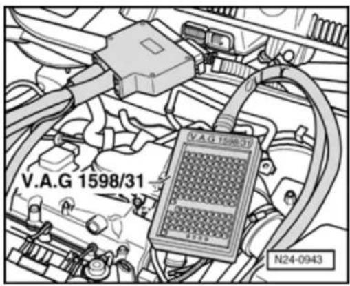
Note:
This work sequence allows the fuel pump to when the engine is not running.
- Insert fuel injector to be checked in a meal glass of calibration tester VAG 1602.
24-108
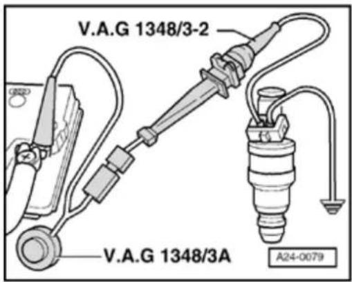

- Connect one terminal of fuel injector to be tested to engine Ground(GND) using adapter cables from VAG 1594.
- Using adapter cables connect the second fuel injector terminal to remote control VAG 1348/3 with adapter cable VAG 1348/3-2.
- Connect alligator clip to battery (+).
- Operate remote control VAG 1348/3 for 30 seconds.
- Repeat check onother fuel injectors. Use another (clean and dry) measuring beaker for this.
- After all fuel injectors have been activated, place measuring glasses on a horizontal surface and compare quantity injected.
Specification: 110 to 130 ml per fuel injector
- Switch off ignition.
If the measured values of one or more fuel injectors are above or below the prescribed specifications:
- Replace faulty fuel injector Page 24-27, item 7.
24-109
Observe the following when installing fuel injectors:
◆ Replace O-rings on all fuel injectors and moisten them lightly with clean engine oil.
◆ Insert fuel injectors vertically and in the correct position into the fuel rail and secure with retaining clips.
◆ Set fuel rail with secured fuel injectors on cylinder head and press in evenly.
- The connectors must audibly engage in the fuel injectors when pushed on.
- Check DTC memory, repair malfunctions if necessary and then erase DTC memory Page 01-23.
- Erase learned values and adapt Motronic Engine Control Module (ECM) -J220- again Page 24-182.
- Read readiness code Page 01-146. If DTC memory has been erased or Motronic Engine Control Module (ECM) -J220- was disconnected from battery positive (B+), readiness code must be generated again Page 01-149.
24-110
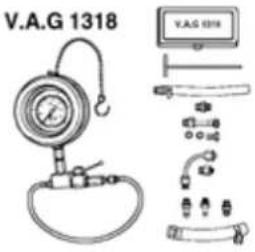 | V.A.G 1318/10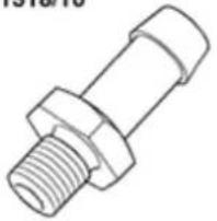 |
V.A.G 1318/11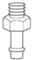 | V.A.G 1318/16 |
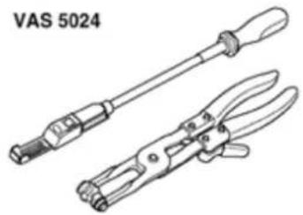 |
Residual pressure and fuel pressure regulator, checking
Special tools and equipment
◆ VAG 1318 Pressure gauge
◆ VAG 1318/10 Adapter
◆ VAG 1318/11 Adapter
◆ VAG 1318/16 Hose adapter
◆ VAS 5024 Assembly tool for spring-type clips
24-111
Function
The fuel pressure regulator regulates the fuel pressure depending on intake manifold pressure.
The specification for the check is dependent upon the working pressure of the fuel pump. This is approx. 3.0 bar
Test requirements
- Fuel pump delivery rate OK., checking:
→ Repair Manual, 2.8 Liter VR6 4V Engine Mechanical, Engine Code(s): BDF; Repair Group 20
24-112

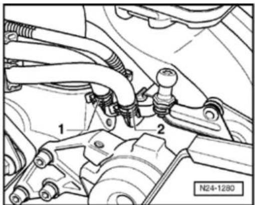
Test sequence

- Pull fuse No. 28 (for fuel pump) out of fuse holder.

- Pull fuel supply hose -1- (black) off fuel rail and collect fuel that leaks out with a cloth.
WARNING!
Fuel system is under pressure! Before opening the system place a cloth around the connection. Then release pressure by carefully loosening the connection.
24-113
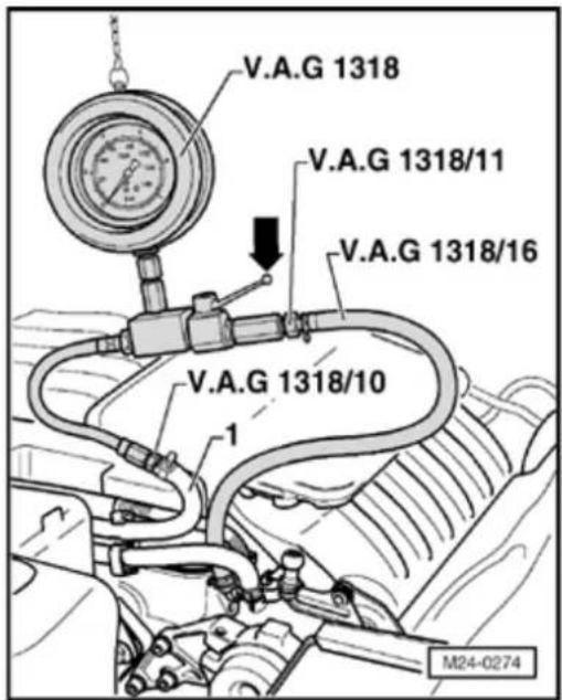
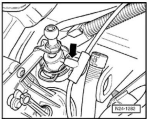
natural_image
Mechanical assembly diagram showing a lever mechanism with no visible text or symbols
- Connect pressure gauge VAG 1318 with adapter, VAG 1318/10 to supply hose -1- and with adapter VAG 1318/11 and VAG 1318/16 hose adapter to supply line.
- O pen shut-off tap on pressure gauge. Handle points in through-flow direction (arrow).
- Install fuel pump fuse No. 28 into fuse holder.
- Start engine and run at idle.
- M easure fuel pressure.
Specification: Approx. 2.5 bar

- Pull vacuum hose off fuel pressure regulator (arrow).
Fuel pressure must increase to approx. 3.0 bar.
- Switch off ignition.
24-114
If the specification is not obtained:
- Check delivery rate of fuel pump:
⇒ Repair Manual, 2.8 Liter VR6 4V Engine Mechanical, Engine Code(s): BDF; Repair (20
If the specification is obtained:
- Now check for leaks and holding pressure. Watch pressure drop on gauge.
After 10 minutes there must be a residual pressure of at least 2.0 bar
If the holding pressure drops below 2 bar:
- Start engine and run at idle.
When the fuel pump has built up the press again:
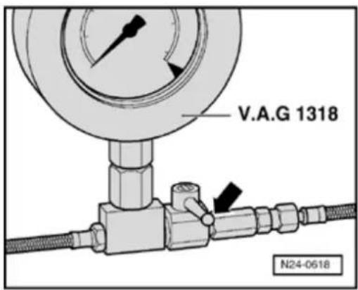
- Switch ignition off after the pressure has up. Simultaneously close pressure gauge 1318 cut-off tap (handle across through-f direction -arrow-).
- Watch pressure drop on gauge again.
24-115
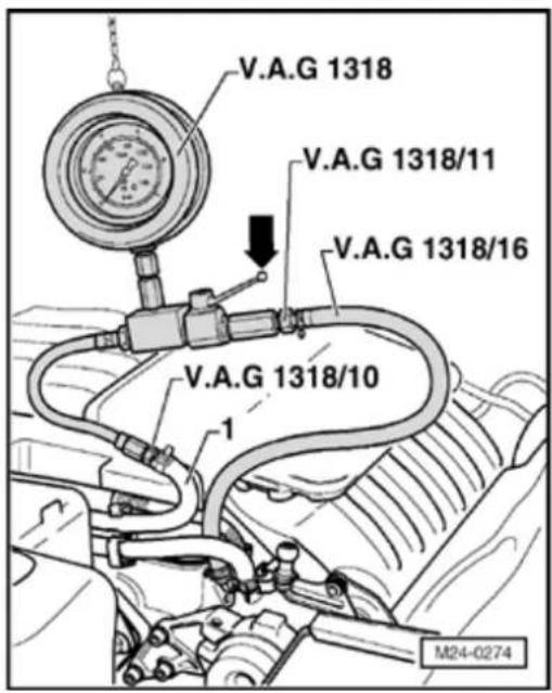
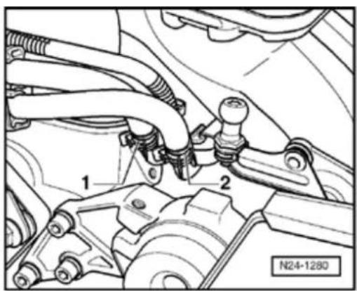
If the pressure does not drop:
- Check fuel pump non-return valve:
→ Repair Manual, 2.8 Liter VR6 4V Engine Mechanical, Engine Code(s): BDF; Repair Group 20
If the pressure drops again:

- O pen pressure gauge VAG 1318 shut-off tap (handle in direction of flow -arrow-).
- Start engine and run at idle speed.

- Switch ignition off after pressure has built-up. Simultaneously clamp-off return supply hose (with blue marking) -2-.
- Switch off ignition.
If the pressure does not drop:
- Replace fuel pressure regulator Page 24-28, item 11.
24-116
If the pressure drops again:
- Check line connections, O-rings on fuel rail and fuel injectors for leaks.
- Check pressure gauge for leaks.
When the pressure gauge is removed after completing the test:
- Remove fuse No. 28 from fuse holder again before removing pressure gauge and place a cloth around connections to be loosened.
24-117
Intake Manifold Change-Over Valve -N156-, checking
The check need only be performed when performance is poor.
The change-over from long to short intake channels occurs at approx. 4400 rpm.
Special tools and equipment


◆ VAG 1551 Scan tool (or VAG 1552) with VAG 1551/3 adapter cable
24-118
Note:
All functions which could previously be performed with VAG 1551/1552 can also be performed with the VAS 5051.
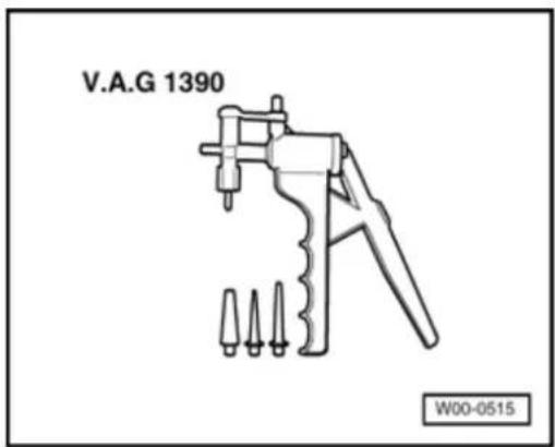
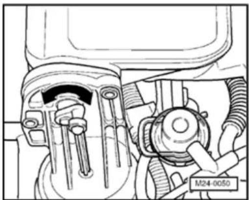
natural_image
Technical line drawing of a mechanical assembly with no visible text or symbols
♦ VAG 1390 Hand vacuum pump
Checking function
- Start engine and run at idle speed.
Actuator (vacuum unit) on intake manifold holds change-over barrel in position for long intake channel.

- Have a second person press accelerator pedal down fully onto limit stop (throttle burst). Observe vacuum unit for Intake Manifold Change-Over Valve -N156-(location: on left of intake manifold).
Actuating element must rotate barrel in intake manifold (arrow).
- Switch off ignition.
24-119
If the actuating element does not perform the change-over sequence:
- Check activation of Intake Manifold Chan Over Valve -N156- via Output Diagnosis Mode (DTM) Page 01-100.
If activation is OK:
- Connect scan tool.
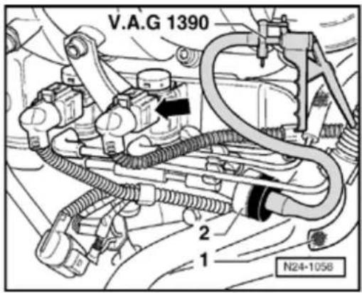

- Pull vacuum hose -1-off non-return valve
- Connect hand vacuum pump VAG 1390 f return valve -2-.
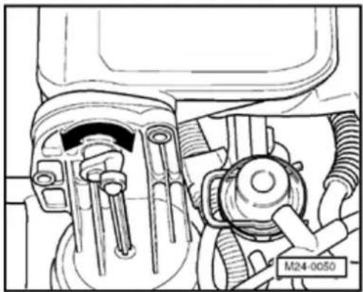
natural_image
Mechanical assembly diagram showing internal components with no visible text or symbols
- Perform Output Diagnosis Test Mode (D ^- again. When Intake Manifold Change-Ov Valve -N156- valve is activated, operate I pump uniformly.
Actuating element must switch back and between both positions.
24-120
If the change-over does not function as described:
- Check change-over mechanics for freedom of movement. Move rods by hand.
- Check vacuum pipes for correct connection.
- Check vacuum system including vacuum reservoir.
Note:
The vacuum reservoir is bolted below the intake manifold.
24-121
Intake Air system, leak testing
Checking with engine leak detector spra 001 800 A1
Note:
The vacuum in the intake system will call leak detector spray to be drawn in with the unmetered air. The leak detector spray is the ignitability of the mixture. This leads to drop in engine speed and to a change of Oxygen Sensor (O2S) reading.
◆ The safety precautions listed on the con must be adhered to.
Special tools, materials and equipment
◆ VAG 1551 Scan tool (or VAG 1552) with 1551/3 adapter cable
Note:
All functions which could previously be performed with VAG 1551/1552 can also be performed by the VAS 5051.
◆ Engine leak detector spray G 001 800 A

24-122
Test sequence
- Connect VAG 1551 Scan tool (or VAG 1552) and select engine electronics control module with "Address word" 01. Engine must be running at idle speed: ((VAG 1551 and Motronic Engine Control Module (ECM) -J220-, connecting and selecting Page 01-12).
Rapid data transfer
Select function XX
HELP

Indicated on display:
- Press buttons -0- and -8- for function "Read measured value (data) block" and confirm entry with -Q- button.
24-123
Read measured value block
Input display group number XXX
Read measured value block 1
1 2 3 4
Indicated on display:
- Press buttons -0-, -0- and -1- for "Display group number 1" and confirm entry with -Q- button.
< Indicated on display: (1...4 = display zones)
- Check whethe Engine Coolant Temperature (ECT) is above 85 °C in display zone 2.
- Observe engine speed in display zone 1 and Oxygen Sensor control before Three Way Catalytic Converter (TWC) in display zones 3 and 4.
- Observe engine speed in display zone 1 and Oxygen Sensor control before Three Way Catalytic Converter (TWC) in display zone 3.
- Systematically spray parts of intake system with engine leak detector spray.
If the engine speed or the Oxygen Sensor control do not change:
- Press → b utton.
- Press buttons -0- and -6- for function "End output" and confirm entry with -Q- button.
- Switch off ignition.
24-124
If the engine speed drops or the Oxygen Sensor control changes:
- Press → b utton.
- Press buttons -0- and -6- for function "End output" and confirm entry with -Q- button.
- Switch off ignition.
- Check sprayed areas of intake system for leaks and correct if necessary.
Functions, checking
Idle speed check
Note:
◆ Idle speed, ignition timing and CO conte adjustable.
◆ The idle speed is regulated to specific the throttle valve positioner in conjunctio the DIS function.
◆ CO content regulated to specification by Oxygen Sensor control. Malfunctions in Sensor control are detected by On Board Diagnostic (OBD) and stored in DTC med
Special tools and equipment
◆ VAG 1551 Scan tool (or VAG 1552) with 1551/3 adapter cable
Note:
All functions which could previously be performed with VAG 1551/1552 can also be performed the VAS 5051.

24-126

Test requirements

• The fuses must be OK.
- The battery voltage must be at least 11.5 V.
- All electrical accessories, e.g. lights and rear window defroster must be switched off.
- If the vehicle is equipped with air conditioning, this must be switched off.
- Selector lever must be in position "P" or "N" on vehicles with an automatic transmission.
- Exhaust system between Three Way Catalytic Converter (TWC) and cylinder head must be free of leaks.
- Engine Coolant Temperature (ECT) must be at least 85 °C, ⇒display group 4, display zone 3.
- Intake air temperature less than 60 °C ⇒ display group 04, display zone 4.
- Three Way Catalytic Converter (TWC) temperature must be at least 380 °C, ⇒d isplay group 34, display zone 2.
24-127
Test sequence
- Connect VAG 1551 Scan tool (or VAG 1552) and select engine electronics control module with "Address word" 01. Engine must be running at idle speed: ((VAG 1551 and Motronic Engine Control Module (ECM) -J220-, connecting and selecting Page 01-12).
- Check DTC memory, repair malfunctions if necessary and then erase DTC memory Page 01-23.
- Then:
- Connect scan tool.
- Continue running engine at idle.
Rapid data transfer
HELP
Select function XX

Indicated on display:
- Press buttons -0- and -4- for function "Initiate basic setting" and confirm entry with -Q- button.
Basic setting
Input display group number XXX

Indicated on display:
- Press buttons -0-, -0- and -1- for "Display group number 1" and confirm entry with -Q- button.
24-128
| System in basic setting 1 | → | ||
| 1 | 2 | 3 | 4 |
Indicated on display: (1 to 4 = display zones)
Note:
In the function "System in basic setting" the Evaporative Emission (EVAP) Canister Purge Regulator Valve -N80- is closed and the air conditioner compressor turned off.
- Check adjustment conditions for basic settings in display zone 4:
Specification: 11111111
Significance of figures in 8 digit number block Page 01-189. - Briefly increase engine speed (rev-up) and then allow engine to run at idle for 2 minutes.
Checking idle speed
- Change to display group 56 as follows:
- Press -C- button.
- Press buttons -0-, -5- and -6- for "Display group number 56" and confirm entry with -Q- button.
| System in basic setting 56 | → | ||
| 1 | 2 | 3 | 4 |
< Indicated on display: (1 to 4 = display zones)
24-129
- Check operating conditions in display zone 4:
Specification: xx000
Significance of figures in 5 digit number block Page 01-240.
- Check specified idle speed in display zone 2.
Specification: 700 rpm
- Check actual idle speed in display zone 1.
Specification: 640 to 720 rpm
- Press → b utton.
- Press buttons 0 and 6 for function "End output" and confirm entry with Q button.
- Switch off ignition.
If the idle speed is not obtained:
- Erase learned values and adapt Motronic Engine Control Module (ECM) -J220- again Page 24-182.
- Road test vehicle.
Observe the valid safety precautions when performing a road test Page 24-33.
24-130
- Check control module DTC memory again.
- Repeat engine idle speed check.
If the specifications are not obtained again:
- Check Throttle Valve Control Module -J338- Page 24-59.
- Check operating condition of engine Page 24-158.
- Check intake air system for leaks (unmetered air) Page 24-121.
- Check signals from / to air conditioning system ⇒ Page 24-194.
24-131
Oxygen Sensor (O2S) and Oxygen Sensor control before Three Way Catalytic Converter (TWC), checking
Note:
◆ The vehicle must be raised to gain acc. the Oxygen Sensor (O2S) connector.
- Only gold plated terminals may be used service the terminals in the Oxygen Sen (O2S) connectors.
The Oxygen Sensor (O2S) before Three Catalytic Converter (TWC) has a continuous regulation and can be differentiated from Oxygen Sensor (O2S) Behind Three Wa Catalytic Converter (TWC) -G130- by its connector.
Special tools, materials and equipment

◆ VAG 1551 Scan tool (or VAG 1552) with 1551/3 adapter cable
Note:
All functions which could previously be performed with VAG 1551/1552 can also be performed by the VAS 5051.
◆ VAG 1526 or Fluke 83 Hand multimeter 1715 multimeter
◆ VAG 1594 Adapter set
24-132

◆ VAG 1598/31 test box
♦ Electrical Wiring Diagrams
Test requirements

• The fuses must be OK.
- The battery voltage must be at least 11.5 V.
- All electrical accessories, e.g. lights and rear window defroster must be switched off.
- If the vehicle is equipped with air conditioning, it must be turned off.
- Selector lever must be in position "P" or "N" on vehicles with an automatic transmission.
• Exhaust system between Three Way Catalytic Converter (TWC) and cylinder head must be free of leaks.
- Engine Coolant Temperature (ECT) must be at least 85 °C, ⇒display group 1, display zone 2.
- Three Way Catalytic Converter (TWC) temperature must be at least 380 °C, =d isplay group 34, display zone 2.
24-133
Functional check
- Connect VAG 1551 Scan tool (or VAG 1552) and select engine electronics control module with "Address word" 01. Engine must be running at idle speed: ((VAG 1551 and Motronic Engine Control Module (ECM) -J220-, connecting and selecting Page 01-12).
Rapid data transfer
HELP

Select function XX
Indicated on display:
- Press buttons -0- and -8- for function "Read measured value (data) block" and confirm entry with -Q- button.
Read measured value block

Input display group number XXX
Indicated on display:
- Press buttons -0-, -3- and -0- for "Display group number 30" and confirm entry with -Q- button.
Read measured value block 30

1
2

Indicated on display: (1 to 2 = display zones)
- Check Oxygen Sensor control status before Three Way Catalytic Converter (TWC) (display zone 1):
Specification: 111
Significance of figures in 3 digit number block Page 01-217.
24-134
Note:
The bits in display zone 1 will not be set to 1 until the Three Way Catalytic Converter (TWC) temperature rises above 380^ ( display groups 34, display zone 2).
If the specification is not obtained:
- Press → b utton.
- Check Heated Oxygen Sensor (HO2S) Page 24-38.
If the specification is obtained:
- Change to display group 32 as follows:
- Press -C- button.
Read measured value block
Input display group number XXX
Indicated on display:
- Press buttons -0-, -3- and -2- for "Display group number 32" and confirm entry with -Q- button.
Read measured value block 32
1 2
Indicated on display: (1 to 2 = display zones)
- Check Oxygen Sensor learned values at idle speed (additive) in display zone 1.
Specification: -5.4 to 5.4 %
24-135
- Check Oxygen Sensor learned values at part load (multiple active) in display zone 2.
Specification: -10.0 to 10.0%
If the specifications are not obtained:
- Press → b utton.
- Press buttons -0- and -6- for function "End output" and confirm entry with -Q- button.
- Switch off ignition.
- Evaluate display group 32 Page 01-221.
If the specifications are obtained:
- Change to display group 33 as follows:
VAG 1551: Press button -3-
VAG 1552: Press ↑ b utton

Indicated on display: (1 to 2 = display zones)
- Check Oxygen Sensor control in display zone 1. Display must fluctuate in range of -10.0 to 10.0% by at least 2%.
- Check Oxygen Sensor control in display zone 2. Display must fluctuate in range of 1.400 to 1.600 V.
24-136
If the displays in display zones 1 and 2 fluctuate:
- Press → b utton.
- Press buttons -0- and -6- for function "End output" and confirm entry with -Q- button.
- Switch off ignition.
If one or both of the displays in zones 1 and 2 display a value constantly:
- Press → b utton.
- Press buttons -0- and -6- for function "End output" and confirm entry with -Q- button.
- Switch off ignition.
- Check wiring of Heated Oxygen Sensor (HO2S) Page 24-138.
If the Oxygen Sensor control in display zone 1 does not fluctuate in the stated range:
- Press → b utton.
- Press buttons -0- and -6- for function "End output" and confirm entry with -Q- button.
24-137
- Road test vehicle to remove possible contaminates on Oxygen Sensor (O2S) and repeat check.
Observe the valid safety precautions when performing a road test Page 24-33.
If the specifications in display zone 1 are not obtained even after a road test, or the value does not fluctuate by at least 2%:
- Check Heated Oxygen Sensor (HO2S) for aging ⇒ Page 24-150.
Possible causes of Diagnostic Trouble Code (DTC) when continuous regulation of sensor is too slow:
◆ The slots or holes in sensor body are blocked
◆ The sensor breather hole in area of connecting cable is blocked
◆ The sensor has been overheated (glazed)
◆ The sensor has been damaged by leaded fuel
24-138
Checking wiring for Heated Oxygen Sensor (HO2S)
- Remove wiper arms and cowl panel:
⇒ Repair Manual, Electrical Equipment; Repair Group 92

- Connect VAG 1598/31 test box to control module wiring harness. Engine Control Module (ECM) - J220- remains disconnected.
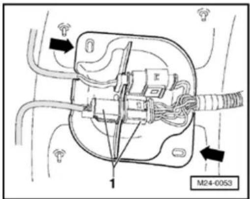
- Remove protective cover (arrows) and disconnect 6-pin connector (black) -1- to Heated Oxygen Sensor (HO2S) -G39-.
24-139
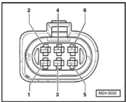

- Check wiring for open circuit between test box and 6-pin connector (to control module) referring to Electrical Wiring Diagrams.
Terminal 1 and socket 70
Terminal 2 and socket 71
Terminal 5 and socket 51
Terminal 6 and socket 52
Wire resistance: max. 1.5 Ω
- Additionally check wires all for short to one another.
Specification: ∞ Ω
If no wiring malfunction is detected:
- Replace Heated Oxygen Sensor (HO2S) -G39- Page 24-19, item 20.
- Check DTC memory, repair malfunctions if necessary and then erase DTC memory Page 01-23.
- Erase learned values and adapt Motronic Engine Control Module (ECM) -J220- again Page 24-182.
- Read readiness code Page 01-146. If DTC memory has been erased or Motronic Engine Control Module (ECM) -J220- was disconnected from battery positive (B+), readiness code must be generated again Page 01-149.
24-140
Oxygen Sensor (O2S) and Oxygen Sensor control after Three Way Cata Converter (TWC), checking
Note:
◆ The vehicle must be raised to gain access. the Oxygen Sensor (O2S) connector.
- Only gold plated terminals may be used service the terminals in the Oxygen Sen (O2S) connectors.
Special tools, materials and equipment
◆ VAG 1551 Scan tool (or VAG 1552) with 1551/3 adapter cable
Note:
All functions which could previously be performed with VAG 1551/1552 can also be performed by the VAS 5051.
◆ VAG 1526 or Fluke 83 Hand multimeter 1715 multimeter
◆ VAG 1594 Adapter set
◆ VAG 1598/31 test box
♦ Electrical Wiring Diagrams

24-141

Test requirements

• The fuses must be OK.
- The battery voltage must be at least 11.5 V.
- All electrical accessories, e.g. lights and rear window defroster must be switched off.
- If the vehicle is equipped with air conditioning, this must be switched off.
- Selector lever must be in position "P" or "N" on vehicles with an automatic transmission.
- Exhaust system between Three Way Catalytic Converter (TWC) and cylinder head must be free of leaks.
- Engine Coolant Temperature (ECT) must be at least 85 °C, ⇒display group 1, display zone 2.
- Three Way Catalytic Converter (TWC) temperature must be at least 380 °C, ⇒d isplay group 34, display zone 2.
24-142
Functional check
- Connect VAG 1551 Scan tool (or VAG 1552) and select engine electronics control module with "Address word" 01. Engine must be running at idle speed: ((VAG 1551 and Motronic Engine Control Module (ECM) -J220-, connecting and selecting Page 01-12).
Rapid data transfer
HELP

Select function XX
Indicated on display:
- Press buttons -0- and -8- for function "Read measured value (data) block" and confirm entry with -Q- button.
Read measured value block

Input display group number XXX
Indicated on display:
- Press buttons -0-, -3- and -0- for "Display group number 30" and confirm entry with -Q- button.
Read measured value block 30

1
2

Indicated on display: (1 to 2 = display zones)
- Check Oxygen Sensor control status after Three Way Catalytic Converter (TWC) (display zone 2). Specification: 111
Significance of figures in 3 digit number block Page 01-217.
24-143
Note:
The bits in display zone 1 will not be set to 1 until the Three Way Catalytic Converter (TWC) temperature rises above 380^ ( display groups 34, display zone 2) and a part load signal is recognized by the Motronic Engine Control Module (ECM) -J220-.
If the specification is not obtained:
- Press → b utton.
- Check Oxygen Sensor (O2S) heating after Three Way Catalytic Converter (TWC) Page 24-45.
If the specification is obtained:
- Change to display group 36 as follows:
- Press -C- button.
Read measured value block
Input display group number XXX
Read measured value block 36
1 2 3 4

Indicated on display:
- Press buttons -0-, -3- and -6- for "Display group number 36" and confirm entry with -Q- button.

Indicated on display: (1 to 4 = display zones)
- Check Oxygen Sensor (O2S) voltage after Three Way Catalytic Converter (TWC) in display zone 1:
Specification: 0.100 to 0.900 V (must fluctuate slightly)
24-144
If the display in display zone 1 fluctuates:
- Press → b utton.
- Press buttons -0- and -6- for function "End output" and confirm entry with -Q- button.
- Switch off ignition.
If the display in display zone 1 remains constantly at a value:
- Press → b utton.
- Press buttons -0- and -6- for function "End output" and confirm entry with -Q- button.
- Switch off ignition.
- Check basic voltage of Oxygen Sensor (O2S) Behind Three Way Catalytic Converter (TWC) - G130- Page 24-146.
- Check Oxygen Sensor (O2S) wiring of Oxygen Sensor (O2S) Behind Three Way Catalytic Converter (TWC) -G130- Page 24-148.
If the Oxygen Sensor control in display zone 1 does not fluctuate in the stated range:
- Press → b utton.
24-145
- Press buttons -0- and -6- for function "End output" and confirm entry with -Q- button.
- Road test vehicle to remove possible residue on Oxygen Sensor (O2S) and repeat check.
Observe the valid safety precautions when performing a road test Page 24-33.
If the specifications in display zone 1 are not obtained even after a road test, or the value does not fluctuate:
- Check Oxygen Sensor (O2S) Behind Three Way Catalytic Converter (TWC) -G130- for aging ⇒ Page 24-154
Possible causes of Diagnostic Trouble Code (DTC) if sensor regulation frequency is too slow:
◆ The slots or holes in sensor body are blocked
◆ The sensor breather hole in area of connecting cable is blocked
◆ The sensor has been overheated (glazed)
◆ The sensor has been damaged by leaded fuel
24-146

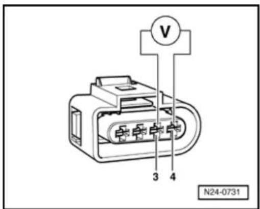
Check basic voltage of Oxygen Sensor (O2S) Behind Three Way Catalytic Converter (TWC) -G130-

- Remove protective cover (arrows) and disconnect 4-pin connector (black) -1- to Oxygen Sensor (O2S) Behind Three Way Catalytic Converter (TWC) -G130-

- Connect multimeter to measure voltage at terminals 3 and 4 (connector to ECM) using adapter cables from VAG 1594.
- Start engine and measure basic voltage.
Specification: 0.400 to 0.500 V
- Switch off ignition.
If the specification is obtained:
- Replace Oxygen Sensor (O2S) Behind Three Way Catalytic Converter (TWC) -G130- → Page 24-17, item 18.
24-147
- Check DTC memory, repair malfunctions if necessary and then erase DTC memory Page 01-23.
- Erase learned values and adapt Motronic Engine Control Module (ECM) -J220- again Page 24-182.
- Read readiness code Page 01-146. If DTC memory has been erased or Motronic Engine Control Module (ECM) -J220- was disconnected from battery positive (B+), readiness code must be generated again Page 01-149.
If the specification is not obtained:
- Check Oxygen Sensor (O2S) wiring of Oxygen Sensor (O2S) Behind Three Way Catalytic Converter (TWC) -G130- Page 24-148.
24-148
Checking wiring for Oxygen Sensor (O2S) Behind Three Way Catalytic Converter (TWC) -G130-
- Remove wiper arms and cowl panel:
⇒ Repair Manual, Electrical Equipment; Repair Group 92


- Connect VAG 1598/31 test box to control module wiring harness. Engine Control Module (ECM) - J220- remains disconnected.


- Remove protective cover (arrows) and disconnect 4-pin connector (black) -1- to Oxygen Sensor (O2S) Behind Three Way Catalytic Converter (TWC) -G130-
24-149
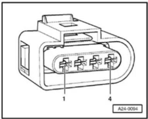

- Check wiring for open circuit between test box and 4-pin connector (to control module) referring to Electrical Wiring Diagrams.
Terminal 3 and socket 68
Terminal 4 and socket 69
Wire resistance: max. 1.5 Ω
- Additionally check wires all for short to one another.
Specification:
If no wiring malfunction is detected:
- Replace Motronic Engine Control Module (ECM) -J220- Page 24-173.
- Check DTC memory, repair malfunctions if necessary and then erase DTC memory Page 01-23.
- Erase learned values and adapt Motronic Engine Control Module (ECM) -J220- again Page 24-182.
- Read readiness code Page 01-146. If DTC memory has been erased or Motronic Engine Control Module (ECM) -J220- was disconnected from battery positive (B+), readiness code must be generated again Page 01-149.
24-150


Heated Oxygen Sensor (HO2S), checking aging
Special tools and equipment

◆ VAG 1551 Scan tool (or VAG 1552) with VAG 1551/3 adapter cable
Note:
All functions which could previously be performed with VAG 1551/1552 can also be performed with the VAS 5051.
Test requirements

• The fuses must be OK.
- The battery voltage must be at least 11.5 V.
- All electrical accessories, e.g. lights and rear window defroster must be switched off.
- If the vehicle is equipped with air conditioning, it must be turned off.
24-151
- Selector lever must be in position "P" or "N" on vehicles with an automatic transmission.
- Exhaust system between Three Way Catalytic Converter (TWC) and cylinder head must be free of leaks.
- Engine Coolant Temperature (ECT) must be at least 85 °C, ⇒display group 1, display zone 2.
- Three Way Catalytic Converter (TWC) temperature must be at least 380 °C, →display group 34, display zone 2.
Functional check
- Connect VAG 1551 Scan tool (or VAG 1552) and select engine electronics control module with "Address word" 01. Engine must be running at idle speed: ((VAG 1551 and Motronic Engine Control Module (ECM) -J220-, connecting and selecting Page 01-12).
Rapid data transfer
HELP

Indicated on display:
Select function XX
- Press buttons -0- and -4- for function "Initiate basic setting" and confirm entry with -Q- button.
Basic setting

Indicated on display:
Input display group number XXX
- Press buttons -0-, -3- and -4- for "Display group number 34" and confirm entry with -Q- button.
24-152
| System in basic setting 34 | → | ||
| 1 | 2 | 3 | 4 |
Indicated on display: (1 to 4 = display zones)
- Depress brake pedal and hold.
- Depress accelerator down to wide open throttle position.
Engine speed will be increased by Motronic Engine Control Module (ECM) -J220- to approx. 2300 rpm. - Depress brake pedal and accelerator down and hold until display in display zone 4 jumps from "Test OFF" to "Test ON."
When performing this test the Three Way Catalytic Converter (TWC) temperature in display zone 2 must be at least 380 °C.
Note:
This process can take approx. 90 seconds.
- Depress and hold brake pedal and accelerator until display zone 4 displays specification "B1-P1 OK.".
- Release brake and accelerator pedals.
- Press → b utton.
- Press buttons -0- and -6- for function "End output" and confirm entry with -Q- button.
24-153
If the display does not indicate as described:
- Road test vehicle to remove possible residue on Oxygen Sensor (O2S) and repeat check.
Observe the valid safety precautions when performing a road test Page 24-33.
If the display does not indicate as described again:
- Check Oxygen Sensor (O2S) and Oxygen Sensor control before Three Way Catalytic Converter (TWC) Page 24-131
24-154
Oxygen Sensor (O2S) Behind Three Way Catalytic Converter (TWC) -G130-, checking aging
Special tools and equipment


◆ VAG 1551 Scan tool (or VAG 1552) with VAG 1551/3 adapter cable
Note:
All functions which could previously be performed with VAG 1551/1552 can also be performed with the VAS 5051.
24-155

Test requirements

• The fuses must be OK.
- The battery voltage must be at least 11.5 V.
- All electrical accessories, e.g. lights and rear window defroster must be switched off.
- If the vehicle is equipped with air conditioning, it must be turned off.
- Selector lever must be in position "P" or "N" on vehicles with an automatic transmission.
- Exhaust system between Three Way Catalytic Converter (TWC) and cylinder head must be free of leaks.
- Coolant temperature must be at least 85 °C, ⇒d isplay group 1, display zone 2.
- Three Way Catalytic Converter (TWC) temperature must be at least 380 °C, ⇒d isplay group 34, display zone 2.
Functional check
- Connect VAG 1551 Scan tool (or VAG 1552) and select engine electronics control module with "Address word" 01. Engine must be running at idle speed: ((VAG 1551 and Motronic Engine Control Module (ECM) -J220-, connecting and selecting Page 01-12).
24-156
Rapid data transfer HELP
Select function XX
Basic setting
Input display group number XXX
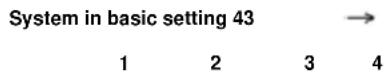
Indicated on display:
- Press buttons -0- and -4- for function "Initiate basic setting" and confirm entry with -Q- button.
< Indicated on display:
- Press buttons -0-, -4- and -3- for "Display group number 43" and confirm entry with -Q- button.
< Indicated on display: (1...4 = display zones)
- Depress brake pedal and hold.
- Depress accelerator down to wide open throttle position.
Engine speed will be increased by Motronic Engine Control Module (ECM) -J220- to approx. 2300 rpm.
- Depress brake pedal and accelerator down and hold until display in display zone 4 jumps from "Test OFF" to "Test ON."
When performing this test the Three Way Catalytic Converter (TWC) temperature in display zone 2 must be at least 380 °C.
Note:
This process can take approx. 30 seconds.
24-157
- Depress and hold brake pedal and accelerator until display zone 4 displays specification "B1-P2 OK."
- Release brake and accelerator pedals.
- Press → b utton.
- Press buttons -0- and -6- for function "End output" and confirm entry with -Q- button.
If the display does not indicate as described:
- Road test vehicle to remove possible residue on Oxygen Sensor (O2S) and repeat check.
Observe the valid safety precautions when performing a road test Page 24-33.
If the display does not indicate as described again:
- Check Oxygen Sensor (O2S) and Oxygen Sensor control after Three Way Catalytic Converter (TWC) Page 24-140.
24-158
Engine operating mode, checking
Note:
The check establishes whether Motronic Engine Control Module (ECM) -J220- recognizes the engine operating modes idling, overrun, part throttle, wide open throttle and enrichment.
Special tools and equipment
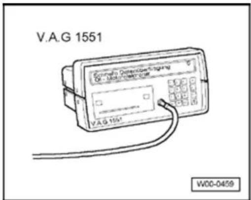

◆ VAG 1551 Scan tool (or VAG 1552) with VAG 1551/3 adapter cable
Note:
All functions which could previously be performed with VAG 1551/1552 can also be performed with the VAS 5051.
Test requirements
- Engine Coolant Temperature (ECT) must be at least 85 °C, ⇒display group 1, display zone 2.
24-159
Test sequence
- Connect VAG 1551 Scan tool (or VAG 1552) and select engine electronics control module with "Address word" 01. Engine must be running at idle speed: ((VAG 1551 and Motronic Engine Control Module (ECM) -J220-, connecting and selecting Page 01-12).
Rapid data transfer
HELP
Select function XX

Indicated on display:
- Press buttons -0- and -8- for function "Read measured value (data) block" and confirm entry with -Q- button.
Read measured value block
Input display group number XXX

Indicated on display:
- Press buttons -0-, -0- and -5- for "Display group number 5" and confirm entry with -Q- button.
Read measured value block 5

1 2 3 4

Indicated on display: (1...4 = display zones)
- Check whether control module recognizes operating conditions (display zone 4):
♦ Idling:
Idling must be displayed as long as the engine is running at idle speed Display: Idling
24-160
Part throttle:
- Rev up evenly.
As long as the engine is being revved up evenly, part throttle must be displayed
Display: Part throt.
◆ Enrichment:
- Floor accelerator pedal (onto throttle valve limit stop).
Acceleration enrichment must be displayed briefly
Display: Enrich.
◆ Overrun mode:
- Increase engine speed to above 3000 rpm.
- Close throttle valve abruptly.
Display: Overrun
Note:
A road test may have to be performed to show "Overrun" in display.
Observe the valid safety precautions when performing a road test Page 24-33.
24-161
◆ Wide open throttle:
- Floor accelerator pedal (onto throttle valve limit stop).
Full load must be displayed briefly
Display: Full load
Note:
A road test may have to be performed to show "Full load" in display.
Observe the valid safety precautions when performing a road test Page 24-33.
- Press → b utton.
- Press buttons -0- and -6- for function "End output" and confirm entry with -Q- button.
If the specifications are not obtained:
- Check DTC memory, repair malfunctions if necessary and then erase DTC memory Page 01-23.
- Check Throttle Valve Control Module -J338- Page 24-59.
- Read readiness code Page 01-146. If DTC memory has been erased or Motronic Engine Control Module (ECM) -J220- was disconnected from battery positive (B+), readiness code must be generated again Page 01-149.
24-162
Motronic Engine Control Module (ECM) -J220-
Function
The Motronic Engine Control Module (ECM) -J220- regulates the injection, Throttle Valve Control Module -J338-, Oxygen Sensor control, ignition, knock regulation, Evaporative Emissions (EVAP) canister purge regulator valve, speed limitation via fuel injectors or Fuel Pump (FP) relay, camshaft timing adjustment as well as On Board Diagnostic (OBD).
24-163

Engine Control Module (ECM) voltage supply, checking
Special tools, materials and equipment

◆ VAG 1551 Scan tool (or VAG 1552) with VAG 1551/3 adapter cable
Note:
All functions which could previously be performed with VAG 1551/1552 can also be performed with the VAS 5051.
◆ VAG 1526 or Fluke 83 Hand
multimeter or VAG 1715
multimeter
◆ VAG 1594 Adapter set
◆ VAG 1598/31 test box
Electrical Wiring Diagrams
24-164


natural_image
Electrical connector diagram showing multiple terminal blocks with wiring (no text or symbols)Test requirements

• The fuses must be OK.

• The main fuses must be OK.
- The battery voltage must be at least 11.5 V.
- All electrical accessories, e.g. lights and rear window defroster must be switched off.
- If the vehicle is equipped with air conditioning, it must be turned off.
- Selector lever must be in position "P" or "N" on vehicles with an automatic transmission.
24-165
- Fuel Pump (FP) -J17- must be OK, checking:
⇒ Electrical Wiring Diagrams, Troubleshooting & Component Locations - Motronic Engine Control Module (ECM) Power Supply Relay -J271- must be OK., checking:
⇒ Electrical Wiring Diagrams, Troubleshooting & Component Locations - Alternator OK., checking:
⇒ Electrical Wiring Diagrams, Troubleshooting & Component Locations
Test sequence
- Connect VAG 1551 Scan tool (or VAG 1552) and select engine electronics control module with "Address word" 01. Engine must be running at idle speed: ((VAG 1551 and Motronic Engine Control Module (ECM) -J220-, connecting and selecting Page 01-12).
Rapid data transfer
HELP

Indicated on display:
Select function XX
- Press buttons -0- and -8- for function "Read measured value (data) block" and confirm entry with -Q- button.
Read measured value block

Indicated on display:
Input display group number XXX
24-166
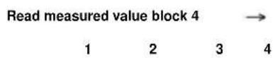
- Press buttons -0-, -0- and -4- for "Display number 4" and confirm entry with -Q- but

Indicated on display: (1 to 4 = display zone
- Read figure displayed in display zone 2. Specification: at least 11.500 V
- Press → b utton.
- Press buttons -0- and -6- for function "En output" and confirm entry with -Q- button. - Switch off ignition.
Evaluating display group 4, display zone 2:01-194.
If the specification is not obtained:
- Remove wiper arms and cowl panel: ⇒ Repair Manual, Electrical Equipment; Re Group 92
- Connect VAG 1598/31 test box to control module wiring harness. Engine Control M (ECM) -J220- remains disconnected.
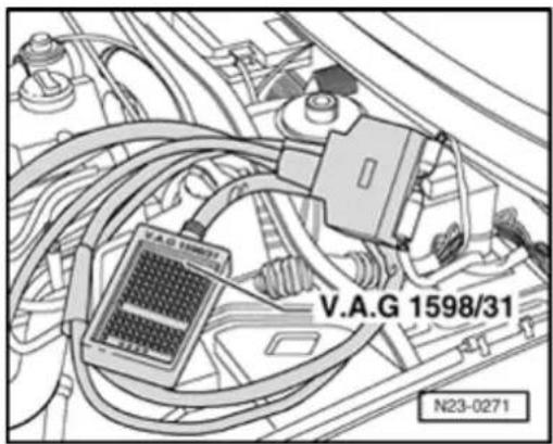
24-167
Checking voltage supply terminal 30
- Measure supply voltage between sockets 1 and 62, and 2 and 62 of test box using multimeter and adapter cables from VAG 1594:
Specification: at least 11.5 V
If the specification is not obtained:
- Check wiring to fuse holder and Ground (GND) connection of Motronic Engine Control Module (ECM) -J220- referring to Electrical Wiring Diagrams:
⇒ Electrical Wiring Diagrams, Troubleshooting & Component Locations
- Check DTC memory, repair malfunctions if necessary and then erase DTC memory Page 01-23.
- Erase learned values and adapt Motronic Engine Control Module (ECM) -J220- again Page 24-182.
- Read readiness code Page 01-146. If DTC memory has been erased or Motronic Engine Control Module (ECM) -J220- was disconnected from battery positive (B+), readiness code must be generated again Page 01-149.
24-168
Checking voltage supply terminal 15
- Measure supply voltage between test box sockets using multimeter and adapter cables from VAG 1594:
S o c k e ts 1 and 3
S o c k e ts 1 and 21
S o c k e ts 2 and 3
S o c k e ts 2 and 21
- Switch on ignition.
Specification: at least 11.5 V
- Switch off ignition.
24-169
If the specification is not obtained:
- Check wiring to fuse holder and Ground (GND) connection of Motronic Engine Control Module (ECM) -J220- referring to Electrical Wiring Diagrams:
⇒ Electrical Wiring Diagrams, Troubleshooting & Component Locations
- Check wiring to Motronic Engine Control Module (ECM) Power Supply Relay -J271 - referring to Electrical Wiring Diagrams:
⇒ Electrical Wiring Diagrams, Troubleshooting & Component Locations
- Check DTC memory, repair malfunctions if necessary and then erase DTC memory Page 01-23.
- Erase learned values and adapt Motronic Engine Control Module (ECM) -J220- again Page 24-182.
- Read readiness code Page 01-146. If DTC memory has been erased or Motronic Engine Control Module (ECM) -J220- was disconnected from battery positive (B+), readiness code must be generated again Page 01-149.
24-170
"Voltage supply open circuit," followup procedure
All values learned by the Motronic Engine Control Module (ECM) - J220- and the basic setting values as well as the readiness code will be erased if the voltage supply is interrupted. Therefore, depending upon the vehicle mileage it can lead to serious engine running problems.
Special tools and equipment


◆ VAG 1551 Scan tool (or VAG 1552) with VAG 1551/3 adapter cable
Note:
All functions which could previously be performed with VAG 1551/1552 can also be performed with the VAS 5051.
24-171
Work sequence
Perform the following operations after interrupting voltage supply:
- Switch ignition on for at least 10 seconds.
- Switch off ignition.
- Erase learned values and adapt Motronic Engine Control Module (ECM) -J220- again Page 24-182.
- Perform idle speed check Page 24-125.
Note:
During idle speed check the Evaporative Emission (EVAP) Canister Purge Regulator Valve -N80- and the air conditioner compressor are switched off and the Oxygen Sensor control learning procedure is initiated.
- Generate readiness code Page 01-149.
- Perform a longer road test until poor driving characteristics are eliminated.
Observe the valid safety precautions when performing a road test Page 24-33.
24-172
During the road test the following operating conditions must be fulfilled:
◆ Engine Coolant Temperature (ECT) must exceed 80 °C.
When the temperature is reached, the operating conditions
Idling
Part throttle
Wide open throttle
Overrun
must be obtained several times.
◆ At wide open throttle the speed must exceed 3500 rpm.
24-173
Motronic Engine Control Module (ECM) -J220-, replacing
Special tools and equipment


◆ VAG 1551 Scan tool (or VAG 1552) with VAG 1551/3 adapter cable
Note:
All functions which could previously be performed with VAG 1551/1552 can also be performed with the VAS 5051.
24-174
Removing
Print out control module identification and thereby previous control module coding as follows:
- Connect VAG 1551 Scan tool (or VAG 1552). Then switch ignition on and select Motronic Engine Control Module (ECM) -J220- with "Address word" 01. ((VAG 1551 and Motronic Engine Control Module (ECM) -J220-, connecting and selecting Page 01-12).
022906032BL MOTRONIC ME7.1.1 G 0006 →
Coding 00032
WSC 00000

The control module identification and coding are shown on the display, e.g.:
- Print out control module identification by pressing Diagnostic Trouble Code (DTC) read print button.
- Press → b utton.
- Press buttons -0- and -6- for function "End output" and confirm entry with -Q- button.
- Switch off ignition.
- Remove wiper arms and cowl panel:
⇒ Repair Manual, Electrical Equipment; Repair Group 92 - Release connector and remove from control module.
24-175
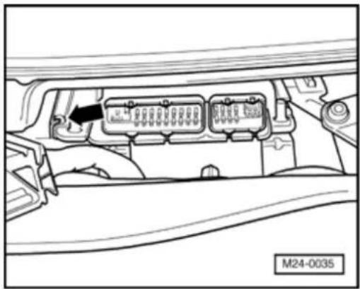

- Press retaining tab (arrow) to left and pull control module out.
Installing
- Place new control module into retaining frame.
- Install control module connector and lock.
- Check previous coding and coding of new control module Page 24-177.
- Adapt new control module to electronic Immobilizer:
⇒ Repair Manual, Electrical Equipment On Board Diagnostic (OBD): Repair Group 01
- Erase learned values and adapt Motronic Engine Control Module (ECM) -J220- again Page 24-182.
Vehicles with cruise control system (CCS)
- Check that system has been activated. If "G" is not evident in control module identification, activate cruise control system:
⇒ Electrical Wiring Diagrams, Troubleshooting & Component Locations
24-176
Vehicles with an automatic transmission
- Also adapt automatic transmission control module:
⇒ Repair Manual, 5 Spd. Automatic Transmission 09A On Board Diagnostic (OBD); Repair Group 01
Continuation for all vehicles
- Check DTC memory, repair malfunctions if necessary and then erase DTC memory Page 01-23.
- Perform idle speed check Page 24-125.
- Generate readiness code Page 01-149.
24-177
Motronic Engine Control Module (EJ220-, coding
Note:
◆ A 5-character code must always be disp during the control module identification.
Measured value block 125 indicates whi control modules are connected via CAN the Motronic Engine Control Module (EC J220-→ Page 01-26 Evaluating meas value (data) block, display groups 120 to Communication-.
The control module must be coded as fc the vehicle relevant coding is not display the control module has been replaced.
Special tools and equipment
◆ VAG 1551 Scan tool (or VAG 1552) with 1551/3 adapter cable
Note:
All functions which could previously be performed with VAG 1551/1552 can also be performed by the VAS 5051.

24-178
Work sequence
- Connect VAG 1551 Scan tool (or VAG 1552). Then switch ignition on and select Motronic Engine Control Module (ECM) -J220- with "Address word" 01. ((VAG 1551 and Motronic Engine Control Module (ECM) -J220-, connecting and selecting Page 01-12).
Rapid data transfer
HELP

Indicated on display:
Select function XX
- Press buttons -0- and -7- for the function "Code control module" and confirm entry with -Q-button.
Code control module

Indicated on display:
Enter code number XXXXX (0-32000)
24-179
022906032BL MOTRONIC ME7.1.1 G 0006 → Coding 00032 WSC 00000
- Enter relevant code number fo vehicle and confirm with -Q- button.
Coding variations of Motronic Engine Control Module (ECM) -J220- Page 24-181.

The control module identification and coding are shown on the display, e.g.:
- Press → b utton.
- Press buttons -0- and -6- for function "End output" and confirm entry with -Q- button.
- Switch off ignition.
- Check DTC memory, repair malfunctions if necessary and then erase DTC memory P 01-23.
- Read readiness code Page 01-146If DT( memory has been erased or Motronic Engine Control Module (ECM) -J220- was disconnected from battery positive (B+) , readiness code must be generated again Page 01-149.

Indicated on display when a non-authorized coc number has been entered.
Function is not recognized or cannot be performed at the moment.
24-180
Note:
The code entered, and shown on the display, will not be used by the Motronic control module until the ignition has been switched off once. An incorrect coding leads to:
◆ Engine running Diagnostic Trouble Code (DTC) s (gear change jolts, load change jerks, etc.)
◆ Increased fuel consumption
♦ Increased exhaust gas emissions
◆ Diagnostic Trouble Code (DTC)s stored in DTC memory which are not actually present (false DTCs)
◆ Functions will not be performed (Oxygen Sensor control, activation of the Evaporative Emissions (EVAP) Canister Purge system, etc.).
◆ Reduced service life of transmission
24-181
Motronic Engine Control Module (ECM) -J220-, coding variations
| 1. position: vehicle code | 2. position: emissions code | 3. position: sensor code | 4. position: CAN-bus | 5. position: transmission code | |||||
| 0 = | No coding | 0 = | No coding | 0 = | No coding | 0 = | No coding | 0 = | No coding |
| 1 = | --- | 1 = | --- | 1 = | --- | 1 = | ABS | 1 = | 5-speed man. transmission |
| 2 = | --- | 2 = | --- | 2 = | --- | 2 = | Airbag | 2 = | 6-speed man. transmission |
| 3 = | --- | 3 = | --- | 3 = | --- | 3 = | ABS and airbag | 3 = | Autom. transmission |
| 4 = | --- | 4 = | --- | 4 = | --- | 4 = | --- | 4 = | --- |
| 5 = | --- | 5 = | --- | 5 = | --- | 5 = | --- | 5 = | --- |
Note:
The code number is compiled as shown in the following example:
| 1. position: Vehicle code (no code at present) | 0 | ||||
| 2. position: Emissions code (no code at present) | 0 | ||||
| 3. position: sensor code (no code at present) | 0 | ||||
| 4. position: CAN-bus code (ABS and airbag) | 3 | ||||
| 5: position: transmission code (6-speed manual transmission) | 2 | ||||
| Code number: | 0 | 0 | 0 | 3 | 2 |
24-182
Motronic Engine Control Module (ECM) - J220- to Throttle Valve Control Module - J338-, matching
Function
First, old learned values are erased. This is necessary to set learned values, which may be at the limit, to a neutral (Diagnostic Trouble Code (DTC) position. The adaptation teaches the Motronic Engine Control Module (ECM) -J220-the various positions of the throttle unit when the ignition is switched on and the engine is not running. These positions are stored in the control module.
Adapting sequence must be performed if:
◆ The voltage supply is interrupted
◆ The Throttle Valve Control Module -J338- has been removed and installed or possibly cleaned
◆ The Throttle Valve Control Module -J338- is replaced
◆ If when installing another engine another Throttle Valve Control Module -J338- is installed
◆ The Motronic Engine Control Module (ECM) - J220- is replaced
◆ Faulty components such as oxygen sensors or fuel injectors have been replaced.
24-183


Special tools and equipment

◆ VAG 1551 Scan tool (or VAG 1552) with VAG 1551/3 adapter cable
Note:
All functions which could previously be performed with VAG 1551/1552 can also be performed with the VAS 5051.
Test requirements

• The fuses must be OK.
- The battery voltage must be at least 11.5 V.
- All electrical accessories, e.g. lights and rear window defroster must be switched off.
- If the vehicle is equipped with air conditioning, it must be turned off.
- Selector lever must be in position "P" or "N" on vehicles with an automatic transmission.
- The throttle valve must be at idle speed position (accelerator must not be depressed during test).
24-184
- The throttle valve must not be soiled (carbon deposits).
- No Diagnostic Trouble Code (DTC)s must be stored in DTC memory Page 01-23.
- Coolant temperature must be 5 to 110^ display group 4, display zone 3.
Work sequence
- Connect VAG 1551 Scan tool (or VAG 1552). Then switch ignition on and select Motronic Engine Control Module (ECM) -J220- with "Address word" 01. ((VAG 1551 and Motronic Engine Control Module (ECM) -J220-, connecting and selecting Page 01-12).
Rapid data transfer
HELP

Select function XX
Indicated on display:
- Press buttons -1- and -0- for function "Adaption" and confirm entry with -Q- button.
Adapting

Feed in channel number XX
Indicated on display:
- Press button -0- button twice- for "Channel number 0" and confirm entry with -Q- button.
Adaption

Erase learned values?

Indicated on display:
- Confirm input with -Q- button.
24-185
Adaption →
learned values have been erased
Rapid data transfer HELP
Select function XX
Basic setting
Input display group number XXX
System in basic setting 60 →
xxx.x % xxx.x % x ADP. runs
Indicated on display:
- Press → b utton.
< Indicated on display:
- Press buttons -0- and -4- for function "Initiate basic setting" and confirm entry with -Q- button.
< Indicated on display:
- Press buttons -0-, -6- and -0- for "Display group number 60" and confirm entry with -Q- button.
< Indicated on display: (1 to 4 = display zones)
After pressing the -Q- button the throttle valve positioner is switched so that it is not supplied with voltage.
In this condition the throttle valve is pulled into an emergency running position by a mechanical spring in the Throttle Valve Control Module - J338-. The values that both angle sensors provide in the emergency running position are stored by the Motronic Engine Control Module (ECM) -J220-.
24-186
Thereafter the throttle valve is opened a predetermined value. If this value is achieved, the throttle valve is again switched so that it is not supplied with voltage. Now the mechanical spring must pull the throttle valve to the previously learned emergency running position within a predetermined period (spring test).
Then the throttle valve is closed by the throttle valve positioner and the values, which are supplied by the angle sensors in the Throttle Valve Control Module -J338-, are stored by the Motronic Engine Control Module (ECM) -J220-.
If the Motronic Engine Control Module (ECM) -J220- switches the throttle valve positioner so that it is without voltage during normal operation, this is indicated by the increased and hunting idle speed. The engine reacts slowly to accelerator changes.
- Check specifications in display zones 3 and 4:
Display zone 3: 0 to 8
Display zone 4: ADP. runs, ADP. OK.
| System in basic setting 60 | → | ||
| xxx % | xxx % | 8 | ADP. OK. |
< Indicated on display: (1 to 4 = display zones)
- Terminate engine basic setting at earliest after 30 seconds by pressing → button.
Adaptation has been performed successfully.
24-187
To store the values:
- Press buttons -0- and -6- for function "End output" and confirm entry with -Q- button.
- Switch off ignition.
Note:
If the basic setting of the control module is aborted, the cause could be one of the following:
◆ The requirements have not been fulfilled.
◆ Throttle Valve Control Module -J338- or wiring is faulty. Check ⇒ Page 24-59.
After aborting, a Diagnostic Trouble Code (DTC) is stored in DTC memory. When next switching on ignition the basic setting is automatically performed again.

Additional signals, checking
Vehicle Speed Signal, checking
Special tools, materials and equipment

◆ VAG 1551 Scan tool (or VAG 1552) with VAG 1551/3 adapter cable
Note:
All functions which could previously be performed with VAG 1551/1552 can also be performed with the VAS 5051.
◆ VAG 1526 or Fluke 83 Hand
multimeter or VAG 1715
multimeter
◆ VAG 1594 Adapter set
◆ VAG 1598/31 test box
Electrical Wiring Diagrams
24-189

Test requirements

• The fuses must be OK.
- The battery voltage must be at least 11.5 V.
- All electrical accessories, e.g. lights and rear window defroster must be switched off.
- If the vehicle is equipped with air conditioning, this must be switched off.
- Selector lever must be in position "P" or "N" on vehicles with an automatic transmission.
• The speedometer must be OK.
Checking speedometer:
⇒ Repair Manual, Electrical Equipment; Repair Group 90
- No Diagnostic Trouble Code (DTC)s must be stored in DTC memory Page 01-23.
24-190
Test sequence
Note:
To check the vehicle speed signal, the vehicle must be driven. To do this a second person is necessary.
WARNING!
Secure test equipment to rear seat and operate it from this position.
- Connect VAG 1551 Scan tool (or VAG 1552) and select engine electronics control module with "Address word" 01. Engine must be running at idle speed: ((VAG 1551 and Motronic Engine Control Module (ECM) -J220-, connecting and selecting Page 01-12).
Rapid data transfer
HELP
Select function XX

Indicated on display:
- Press buttons -0- and -8- for function "Read measured value (data) block" and confirm entry with -Q- button.
Read measured value block
Input display group number XXX

Indicated on display:
- Press buttons -0-, -0- and -5- for "Display group number 5" and confirm entry with -Q- button.
24-191
| Read measured value block 5 | |||
| 1 | 2 | 3 | |
Indicated on display: (1 to 4 = display zones)
- Road test vehicle with a 2nd person to observe display.
Observe the valid safety precautions when performing a road test Page 24-33.
- O bserve figure displayed in display zone 3:
Specification: approx. driven speed
- Drive slower. Displayed value must decrease.
- Press → b utton.
- Press buttons -0- and -6- for function "End output" and confirm entry with -Q- button.
- Switch off ignition.
If no speed is indicated or the display values do not reduce when driving at a lower speed:
- Remove wiper arms and cowl panel:
⇒ Repair Manual, Electrical
Equipment; Repair Group 92
24-192
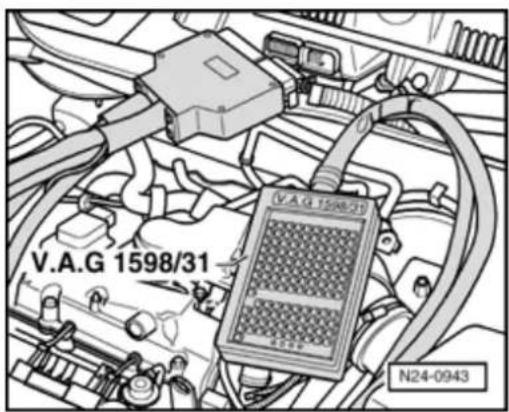

- Connect VAG 1598/31 test box to control module wiring harness. Engine Control Module (ECM) - J220- remains disconnected.
- Connect multimeter to measure voltage between test box sockets 1 (Ground) and 54 (vehicle speed signal) using adapter cables from VAG 1594.
- Raise vehicle at front left.
- Switch on ignition.
- Rotate front wheel and observe voltage display.
Specification: 0.0... at least 4.0 V fluctuating
Note:
Front right wheel must not turn, if necessary, hold to prevent it from turning.
If the display does not fluctuate:
- Check wiring from test box socket 54 to instrument cluster for open/short circuit:
⇒ Electrical Wiring Diagrams, Troubleshooting & Component Locations
24-193
- Check DTC memory, repair malfunctions if necessary and then erase DTC memory Page 01-23.
- Read readiness code Page 01-146. If DTC memory has been erased or Motronic Engine Control Module (ECM) -J220- was disconnected from battery positive (B+), readiness code must be generated again Page 01-149.
24-194

A/C compressor signal, checking
Special tools, materials and equipment

◆ VAG 1551 Scan tool (or VAG 1552) with VAG 1551/3 adapter cable
Note:
All functions which could previously be performed with VAG 1551/1552 can also be performed with the VAS 5051.
◆ VAG 1526 or Fluke 83 Hand
multimeter or VAG 1715
multimeter
◆ VAG 1594 Adapter set
◆ VAG 1598/31 test box
Electrical Wiring Diagrams
24-195

Test requirements

• The fuses must be OK.
- The battery voltage must be at least 11.5 V.
- All electrical accessories, e.g. lights and rear window defroster must be switched off.
- Selector lever must be in position "P" or "N" on vehicles with an automatic transmission.
• Air conditioner functioning OK.
• Air conditioner must be turned off.
- Vehicle at room temperature (warmer than + 15 °C).
- No Diagnostic Trouble Code (DTC)s must be stored in DTC memory Page 01-23.
24-196
Test sequence
- Connect VAG 1551 Scan tool (or VAG 1552) and select engine electronics control module with "Address word" 01. Engine must be running at idle speed: ((VAG 1551 and Motronic Engine Control Module (ECM) -J220-, connecting and selecting Page 01-12).
Rapid data transfer
HELP
Select function XX

Indicated on display:
- Press buttons -0- and -8- for function "Read measured value (data) block" and confirm entry with -Q- button.
Read measured value block
Input display group number XXX

Indicated on display:
- Press buttons -0-, -5- and -0- for "Display group number 50" and confirm entry with -Q- button.
Read measured value block 50

1 2 3 4

Indicated on display: (1 to 4 = display zones)
- Check displays in display zones 3 and 4:
Indicated in display zone 3:
A/C-Low
Indicated in display zone 4:
Compr. OFF
24-197
- Switch on air conditioning system.
- Select lowest temperature and highest blower speed.
The display in display zone 3 must change to:
A/C-High.
The display in display zone 4 must change to:
Compr. ON.
- Press → b utton.
- Press buttons -0- and -6- for function "End output" and confirm entry with -Q- button.
- Switch off ignition.
If the displays do not change as described:
- Remove wiper arms and cowl panel:
⇒ Repair Manual, Electrical Equipment; Repair Group 92
24-198


- Connect VAG 1598/31 test box to control module wiring harness. Engine Control Module (ECM) - J220- remains disconnected.
- Check wiring for open circuit between test box sockets 40 and 41 and air conditioning system referring to Electrical Wiring Diagrams.
Wire resistance: max. 1.5 Ω
If no malfunctions can be found in the wiring:
- Check function of air conditioning system.
- Check DTC memory, repair malfunctions if necessary and then erase DTC memory Page 01-23.
- Read readiness code Page 01-146. If DTC memory has been erased or Motronic Engine Control Module (ECM) -J220- was disconnected from battery positive (B+), readiness code must be generated again Page 01-149.
24-199

Signal from Clutch Vacuum Vent Valve Switch -F36-, checking
Special tools, materials and equipment

◆ VAG 1551 Scan tool (or VAG 1552) with VAG 1551/3 adapter cable
Note:
All functions which could previously be performed with VAG 1551/1552 can also be performed with the VAS 5051.
◆ VAG 1526 or Fluke 83 Hand
multimeter or VAG 1715
multimeter
◆ VAG 1594 Adapter set
◆ VAG 1598/31 test box
Electrical Wiring Diagrams
24-200

Test requirements

• The fuses must be OK.
- The battery voltage must be at least 11.5 V.
- All electrical accessories, e.g. lights and rear window defroster must be switched off.
- If the vehicle is equipped with air conditioning, this must be switched off.
- Selector lever must be in position "P" or "N" on vehicles with an automatic transmission.
Test sequence
- Connect VAG 1551 Scan tool (or VAG 1552). Then switch ignition on and select Motronic Engine Control Module (ECM) -J220- with "Address word" 01. ((VAG 1551 and Motronic Engine Control Module (ECM) -J220-, connecting and selecting Page 01-12).
Rapid data transfer
HELP
Select function XX

Indicated on display:
- Press buttons -0- and -8- for function "Read measured value (data) block" and confirm entry with -Q- button.
24-201
Read measured value block
Input display group number XXX
Read measured value block 66
1 2 3 4
Indicated on display:
- Press buttons -0-, -6- and -6- for "Display group number 66" and confirm entry with -Q- button.
< Indicated on display: (1...4 = display zones)
- Observe display in display zone 2 (6th digit from left).
Specification: xxxxx0xx
- Depress clutch pedal fully and observe values in display zone 2.
Specification: xxxxx1xx
- Press → b utton.
- Press buttons -0- and -6- for function "End output" and confirm entry with -Q- button.
- Switch off ignition.
If the specifications are not obtained:
- Remove cover in footwell (driver's side).
24-202
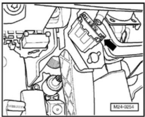
natural_image
Technical line drawing of a mechanical assembly with no visible text or symbols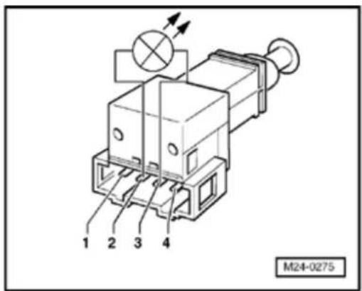
- Disconnect 4-pin connector from Clutch Vacuum Vent Valve Switch -F36- (arrow).
- M easure resistance between switch terminals 2 and 3. Specification: Clutch not depressed: max. 1.5 Ω Clutch depressed: ∞ Ω
If the specifications are not obtained:
- Replace Clutch Vacuum Vent Valve Switch -F36-.
Note:
Observe installation position of Clutch Vacuum Vent Valve Switch - F36- through upper assembly hole of bearing bracket.
24-203
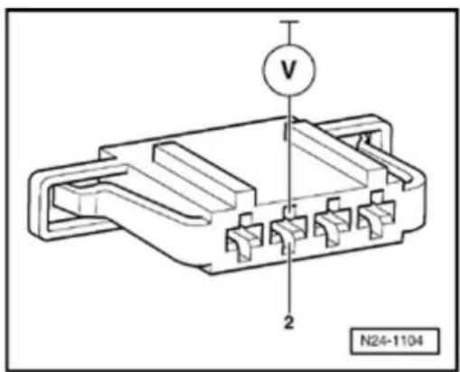
- Check DTC memory, repair malfunctions necessary and then erase DTC memory 01-23.
- Read readiness code Page 01-146. If memory has been erased or Motronic En Control Module (ECM) -J220- was discor from battery positive (B+), readiness code be generated again Page 01-149.
If the specifications are obtained:
- Connect multimeter to measure voltage a connector terminal 2 and engine Ground
- Switch ignition on.
Specification: at least 11.5 V
- Switch ignition off.
If the specification is not obtained:
- Check wire for open circuit between 4-pir connector terminal 2 and Fuel Pump (FP)-J17- referring to Electrical Wiring Diagra
Wire resistance: max. 1.5 Ω
24-204


If the specification is obtained:
- Remove wiper arms and cowl panel:
⇒ Repair Manual, Electrical Equipment; Repair Group 92

- Connect VAG 1598/31 test box to control module wiring harness. Engine Control Module (ECM) - J220- remains disconnected.

- Check wiring for open circuit between test box and 4-pin connector referring to Electrical Wiring Diagrams.
Terminal 3 and socket 39
Wire resistance: max. 1.5 Ω
- Additionally check wiring for short to one another, to vehicle Ground (GND) and to battery positive.
Specification: ∞ Ω
24-205
If there is no Diagnostic Trouble Code (DTC) in the wiring and the resistance measurement values are OK.:
- Replace Motronic Engine Control Module (ECM) -J220- Page 24-173.
- Check DTC memory, repair malfunctions if necessary and then erase DTC memory Page 01-23.
- Erase learned values and adapt Motronic Engine Control Module (ECM) -J220- again Page 24-182.
- Read readiness code Page 01-146. If DTC memory has been erased or Motronic Engine Control Module (ECM) -J220- was disconnected from battery positive (B+), readiness code must be generated again Page 01-149.
24-206

Brake Light Switch -F- and Brake Pedal Switch (cruise control/Diesel Direct Fuel Injection) -F47- signal, checking
Special tools, materials and equipment

◆ VAG 1551 Scan tool (or VAG 1552) with VAG 1551/3 adapter cable
Note:
All functions which could previously be performed with VAG 1551/1552 can also be performed with the VAS 5051.
◆ VAG 1526 or Fluke 83 Hand
multimeter or VAG 1715
multimeter
◆ VAG 1594 Adapter set
◆ VAG 1598/31 test box
Electrical Wiring Diagrams
24-207

Test requirements

• The fuses must be OK.
- The battery voltage must be at least 11.5 V.
- All electrical accessories, e.g. lights and rear window defroster must be switched off.
- If the vehicle is equipped with air conditioning, it must be turned off.
- Selector lever must be in position "P" or "N" on vehicles with an automatic transmission.
Test sequence
- Connect VAG 1551 Scan tool (or VAG 1552). Then switch ignition on and select Motronic Engine Control Module (ECM) -J220- with "Address word" 01. ((VAG 1551 and Motronic Engine Control Module (ECM) -J220-, connecting and selecting Page 01-12).
Rapid data transfer
HELP
Select function XX

Indicated on display:
24-208
Read measured value block Input display group number XXX
Read measured value block 66 → 1 2 3 4
- Press buttons -0- and -8- for function "Read measured value (data) block" and confirm entry with -Q- button.
Indicated on display:
- Press buttons -0-, -6- and -6- for "Display group number 66" and confirm entry with -Q- button.
Indicated on display: (1 to 4 = display zones)
- Observe display in display zone 2: (7th and 8th positions from left).
Specification: xxxxxx00 - Depress brake pedal and observe display in display zone 2.
Specification: xxxxxx11 - Press → b utton.
- Press buttons -0- and -6- for function "End output" and confirm entry with -Q- button.
- Switch off ignition.
If the specifications are not obtained:
- Remove cover in footwell (driver's side).
24-209
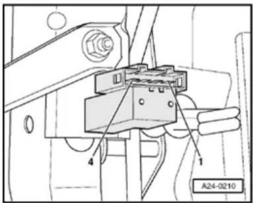
- Disconnect 4-pin connector from Brake L Switch -F- and Brake Pedal Switch (cruis control/Diesel Direct Fuel Injection) -F47-
- Measure resistance between terminals 1 of switch.
Specification:
Brake pedal not depressed: ∞ Ω
Brake pedal depressed: max. 1.5 Ω
- Measure resistance between terminals 2 of switch.
Specification:
Brake pedal not depressed: Max. 1.5 Ω
Brake pedal depressed: ∞ Ω
If the specifications are not obtained:
- Replace Brake Light Switch -F- and Brak Switch (cruise control/Diesel Direct Fuel Injection) -F47-.
- Check DTC memory, repair malfunctions necessary and then erase DTC memory 01-23.
- Read readiness code Page 01-146. If memory has been erased or Motronic En Control Module (ECM) -J220- was discor from battery positive (B+) , readiness code be generated again Page 01-149.
24-210

If the specifications are obtained:

- Connect multimeter to measure voltage between terminal 1 and Ground (GND).
Specification: at least 11.5 V
If the specification is not obtained:
- Check wiring connections to fuse holder for open circuit referring to Electrical Wiring Diagrams.
Wire resistance: max. 1.5 Ω
If the specification is obtained:
- Connect multimeter to measure voltage between terminal 2 and Ground (GND).
- Switch on ignition.
Specification: at least 11.5 V
- Switch off ignition.
If the specification is not obtained:
- Check wire for open circuit between 4-pin connector terminal 2 and Fuel Pump (FP) Relay - J17- referring to Electrical Wiring Diagrams.
Wire resistance: max. 1.5 Ω
24-211

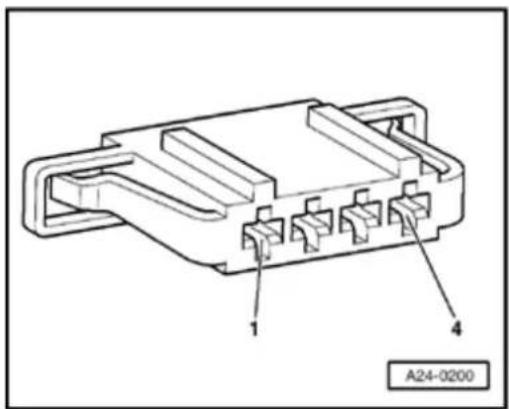
If the specification is obtained:
- Remove wiper arms and cowl panel:
⇒ Repair Manual, Electrical Equipment; Repair Group 92

- Connect VAG 1598/31 test box to control module wiring harness. Engine Control Module (ECM) - J220- remains disconnected.

- Check wiring for open circuit between test box and 4-pin connector referring to Electrical Wiring Diagrams.
Terminal 3 and socket 55
Terminal 4 and socket 56
Wire resistance: max. 1.5 Ω
- Additionally check wiring for short to one another, to vehicle Ground (GND) and to battery positive.
Specification:
24-212
If there is no Diagnostic Trouble Code (DTC) in the wiring and the resistance measurement values are OK.:
- Replace Motronic Engine Control Module (ECM) -J220- Page 24-173.
- Check DTC memory, repair malfunctions if necessary and then erase DTC memory Page 01-23.
- Erase learned values and adapt Motronic Engine Control Module (ECM) -J220- again Page 24-182.
- Read readiness code Page 01-146. If DTC memory has been erased or Motronic Engine Control Module (ECM) -J220- was disconnected from battery positive (B+), readiness code must be generated again Page 01-149.
24-213
Transmission Range signal, checking
Vehicles with an automatic transmission
The Motronic Engine Control Module (ECM) -J220- receives the following information from the transmission control module:
Driving range selected (selector lever in 2/3/4/R/D)
or
No transmission range selected (selector lever in P or N)
24-214
Special tools and equipment

◆ VAG 1551 Scan tool (or VAG 1552) with VAG 1551/3 adapter cable
Note:
All functions which could previously be performed with VAG 1551/1552 can also be performed with the VAS 5051.
24-215

Test requirements

• The fuses must be OK.
- The battery voltage must be at least 11.5 V.
- All electrical accessories, e.g. lights and rear window defroster must be switched off.
- If the vehicle is equipped with air conditioning, it must be turned off.
- Selector lever must be in position "P" or "N" on vehicles with an automatic transmission.
24-216
Test sequence
- Connect VAG 1551 Scan tool (or VAG 1552) and select engine electronics control module with "Address word" 01. Engine must be running at idle speed: ((VAG 1551 and Motronic Engine Control Module (ECM) -J220-, connecting and selecting Page 01-12).
Rapid data transfer
HELP
Select function XX

Indicated on display:
- Press buttons -0- and -8- for function "Read measured value (data) block" and confirm entry with -Q- button.
Read measured value block
Input display group number XXX

Indicated on display:
- Press buttons -0-, -5- and -6- for "Display group number 56" and confirm entry with -Q- button.
Read measured value block 56

1 2 3 4

Indicated on display: (1 to 4 = display zones)
- Observe display in display zone 4 (4th digit from left).
Specification: xxx0x "Neutral"
- Depress brake pedal and select driving range. Observe figure displayed in display zone 4:
Specification: xxx1x "Driving range selected"
- Press → b utton.
24-217
- Press buttons -0- and -6- for function "End output" and confirm entry with -Q- button.
- Switch off ignition.
If the specifications are not obtained:
- Check CAN-bus matching resistor Page 24-223.
- Check DTC memory, repair malfunctions if necessary and then erase DTC memory Page 01-23.
- Read readiness code Page 01-146. If DTC memory has been erased or Motronic Engine Control Module (ECM) -J220- was disconnected from battery positive (B+), readiness code must be generated again Page 01-149.
24-218

Cruise Control System (CCS), checking
Special tools, materials and equipment

◆ VAG 1551 Scan tool (or VAG 1552) with VAG 1551/3 adapter cable
Note:
All functions which could previously be performed with VAG 1551/1552 can also be performed with the VAS 5051.
◆ VAG 1526 or Fluke 83 Hand
multimeter or VAG 1715
multimeter
◆ VAG 1594 Adapter set
◆ VAG 1598/31 test box
Electrical Wiring Diagrams
24-219

Test requirements

• The fuses must be OK.
- The battery voltage must be at least 11.5 V.
- All electrical accessories, e.g. lights and rear window defroster must be switched off.
- If the vehicle is equipped with air conditioning, this must be switched off.
- Selector lever must be in position "P" or "N" on vehicles with an automatic transmission.
Test sequence
- Connect VAG 1551 Scan tool (or VAG 1552). Then switch ignition on and select Motronic Engine Control Module (ECM) -J220- with "Address word" 01. ((VAG 1551 and Motronic Engine Control Module (ECM) -J220-, connecting and selecting Page 01-12).
Rapid data transfer
HELP
Select function XX

Indicated on display:
- Press buttons -0- and -8- for function "Read measured value (data) block" and confirm entry with -Q- button.
24-220
Read measured value block
Input display group number XXX
Read measured value block 66
1 2 3 4
Indicated on display:
- Press buttons -0-, -6- and -6- for "Display group number 66" and confirm entry with -Q- button.
< Indicated on display: (1 to 4 = display zones)
Vehicles with an automatic transmission
- Perform a road test and exceed a speed of 25 km/h once then switch engine off and leave selector lever in position 2, 3, or D.
Observe the valid safety precautions when performing a road test Page 24-33.
- Apply parking brake.
24-221
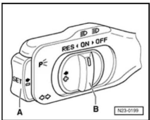
Continuation for all vehicles

- Check specification for switch position of CCS operating switch in display zone 4.
| Test requirements | Display zone 4 |
| Switch B at "OFF", in detent | xxxxxxx0 |
| Switch B at "OFF", in detent or not in detent | xxxxxx0x |
| Switch B at "ON" | xxxxxx11 |
| Switch A depressed (Switch B at "ON") | xxxxx111 |
| Switch B at "RES" | xxxx1xxx |
- Press → b utton.
- Press buttons -0- and -6- for function "End output" and confirm entry with -Q- button.
- Switch off ignition.
24-222

If the specifications are not obtained:
- Remove wiper arms and cowl panel:
⇒ Repair Manual, Electrical Equipment; Repair Group 92

- Connect VAG 1598/31 test box to control module wiring harness. Engine Control Module (ECM) - J220- remains disconnected.
- Check wiring for open/short circuit from Motronic Engine Control Module (ECM) -J220- to CCS operating switch:
⇒ Electrical Wiring Diagrams, Troubleshooting & Component Locations
- Check DTC memory, repair malfunctions if necessary and then erase DTC memory Page 01-23.
- Read readiness code Page 01-146. If DTC memory has been erased or Motronic Engine Control Module (ECM) -J220- was disconnected from battery positive (B+), readiness code must be generated again Page 01-149.
24-223
CAN-bus, checking
Function
The Motronic Engine Control Module (ECM) -J220- communicates with other CAN-bus compatible control modules via a CAN-bus.
These CAN-bus-capable components are connected by a pair of twisted CAN-bus wires (CAN high and CAN low) and exchange information (messages). Information missing from the CAN-bus is recognized as an error and stored.
The CAN-bus requires a matching resistor to function fault free. This matching resistor is located in the Motronic Engine Control Module (ECM) -J220-.
24-224

Special tools, materials and equipment

◆ VAG 1551 Scan tool (or VAG 1552) with VAG 1551/3 adapter cable
Note:
All functions which could previously be performed with VAG 1551/1552 can also be performed with the VAS 5051.
◆ VAG 1526 or Fluke 83 Hand
multimeter or VAG 1715
multimeter
◆ VAG 1594 Adapter set
◆ VAG 1598/31 test box
Electrical Wiring Diagrams
24-225
Test requirements
- The CAN-bus On Board Diagnostic (OBD) has detected a Diagnostic Trouble Code (DTC).
Test sequence
- Remove wiper arms and cowl panel:
⇒ Repair Manual, Electrical Equipment; Repair Group 92
- Connect VAG 1598/31 test box to Motronic Engine Control Module (ECM) -J220-. ECM wiring harness is not connected by this action.
- Check centralized matching resistor in Motronic Engine Control Module (ECM) -J220-. To do this, check resistance between test box
S o c k e ts 58 and 60.
Specification: 60 to 72 Ω
24-226
If the resistance measurement is not within the specified range:
- Replace Motronic Engine Control Module (ECM) -J220- Page 24-173.
- Check DTC memory, repair malfunctions if necessary and then erase DTC memory Page 01-23.
- Erase learned values and adapt Motronic Engine Control Module (ECM) -J220- again Page 24-182.
- Read readiness code Page 01-146. If DTC memory has been erased or Motronic Engine Control Module (ECM) -J220- was disconnected from battery positive (B+), readiness code must be generated again Page 01-149.
24-227
If the resistance value is within the specified range:
- Repair Diagnostic Trouble Code (DTC):
⇒ Electrical Wiring Diagrams, Troubleshooting & Component Locations - Check DTC memory, repair malfunctions if necessary and then erase DTC memory Page 01-23.
- Erase learned values and adapt Motronic Engine Control Module (ECM) -J220- again Page 24-182.
- Read readiness code Page 01-146. If DTC memory has been erased or Motronic Engine Control Module (ECM) -J220- was disconnected from battery positive (B+), readiness code must be generated again Page 01-149.
Ignition system, servicing
General notes on ignition system
Note:
Only the components which specifically relate to the ignition system are dealt with here. For the other components of the injection and ignition system Repair Group 24.
◆ The Engine Control Module (ECM) is equipped with On Board Diagnostic (OBD).
◆ Components marked with * are checked via On Board Diagnostic (OBD) ⇒ Page 01-23.
Components marked with **can be checked via Output Diagnostic Test Mode (DTM) ⇒ Page 01-100.
For trouble-free operation of the electrical components, a voltage of at least 11.5 V is necessary.
◆ Disconnecting and connecting the battery must only be done with the ignition switched off, otherwise the Engine Control Module (ECM) could be damaged.
◆ Check DTC memory before carrying out repairs and for troubleshooting ⇒ Page 01-23.
During some checks it is possible that the control module will detect and store a Diagnostic Trouble Code (DTC). Therefore after completing all checks and repairs the DTC memory must be checked and if necessary erased Page 01-23, and then generate the readiness code Page 01-149.
28-2
If the engine starts, runs for a short period and then stops, after troubleshooting, repairs or component tests, then the malfunction may lie with the Immobilizer which is blocking the Engine Control Module (ECM). In such cases the DTC memory must be checked and, if necessary, the control module adapted.
⇒ Repair Manual, Electrical Equipment On Board Diagnostic (OBD); Repair Group 01
Safety precautions Page 28-12.
Test data, spark plugs Page 28-15.
28-3

Ignition system components, removing and installing
Note:
Engine Control Module (ECM) with connectors Page 24-14, item 8.
1 - Connector
◆ Black, 4-pin
Mark connector and component before pulling connector off.
2 - Ignition coil with power output stages (-N70-, -N127-, -N291-, -N292-, -N323- and -N324-)
◆ Remove using puller T10095
◆ Checking ⇒ Page 28-23
3 - Control housing
◆ For camshaft timing adjustment
◆ Removing and installing:
⇒ Repair Manual, 2.8 Liter VR6 4V Engine Mechanical, Engine Code (s): BDF; Repair Group 15

4 - Bracket
◆ For Knock sensor (KS) 1 - G61- connection
◆ Component location: on right of cylinder head
5 - 10 Nm
6 - 3-pin connector
Black
◆ Gold plated terminals
7 - Knock Sensor (KS) 1 - G61-\*
◆ Component location: between cyl. 1 and cyl. 3
◆ Terminal surfaces between knock sensor and cylinder block must be free of corrosion, dirt and grease.
◆ Checking ⇒ Page 28-30
8 - 20 Nm
♦ Torque setting influences function of knock sensor
28-5
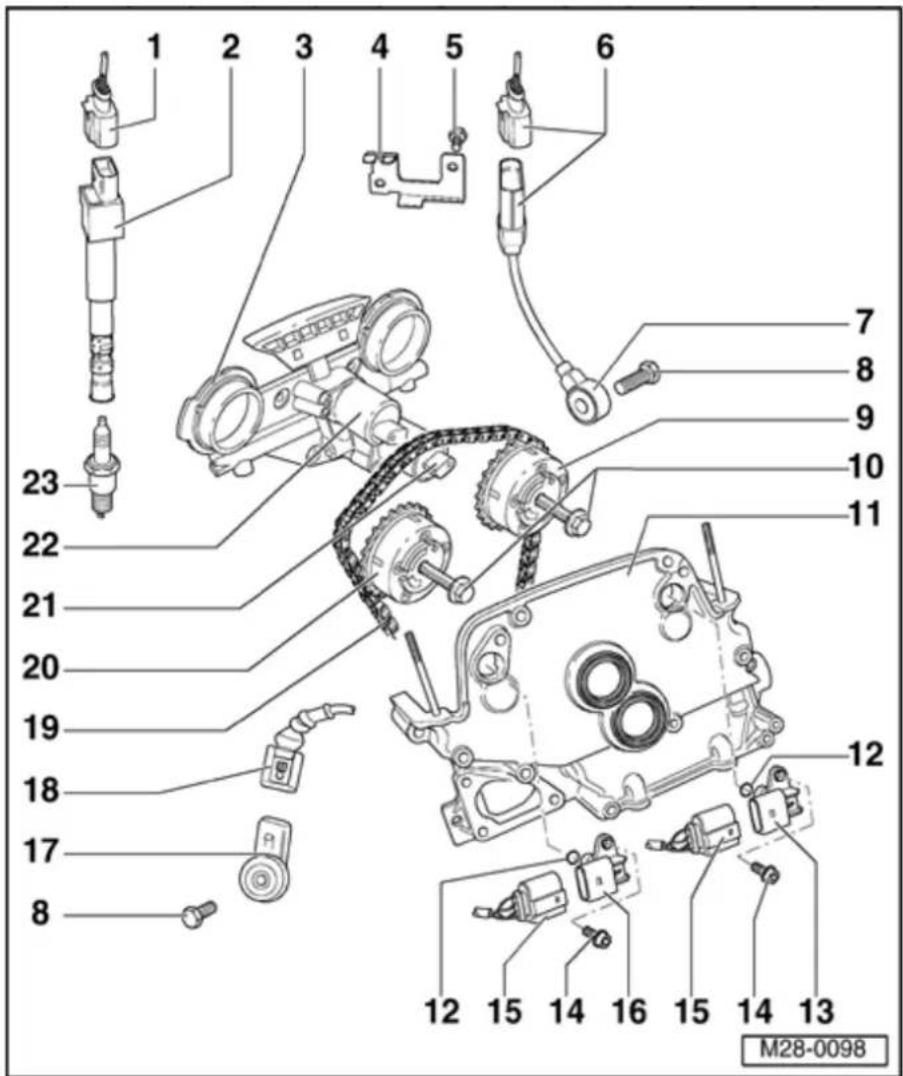
9 - Exhaust camshaft timing adjuster
◆ Marking: 32A
◆ Turn engine over only when camshaft timing adjuster is installed
With sensor wheel for Camshaft Position (CMP) Sensor 2 -G163-
If camshaft timing adjuster has been removed, after installing check timing:
⇒ Repair Manual, 2.8 Liter VR6 4V Engine Mechanical, Engine Code (s): BDF; Repair Group 15
◆ Check camshaft timing adjustment:
⇒ Repair Manual, 2.8 Liter VR6 4V Engine Mechanical, Engine Code (s): BDF; Repair Group 15

10 60 Nm
- plus additional 90° turn
♦ Replace
◆ Terminal surface of sensor wheel on bolt head must be dry for assembly
To remove and install, use a 32 mm open jaw wrench on camshaft as a counter-hold:
⇒ Repair Manual, 2.8 Liter VR6 4V Engine Mechanical, Engine Code (s): BDF; Repair Group 15
11 - Cover
◆ Removing and installing:
⇒ Repair Manual, 2.8 Liter VR6 4V Engine Mechanical, Engine Code (s): BDF;
Repair Group 15
12 - Seal
◆ Replace
13 Camshaft - Position (CMP) Sensor 2 -G163-*
◆ For exhaust camshaft
◆ Sensor and connector terminals are gold plated
◆ Checking ⇒ Page 28-16
28-7

14 - 10 Nm
15 Connector
◆ Black, 3-pin
◆ Sensor and connector terminals are gold plated
Mark connector and component before pulling connector off.
16 Camshaft - Position (CMP) Sensor - G40-\*
◆ For intake camshaft
◆ Sensor and connector terminals are gold plated
◆ Checking ⇒ Page 28-16
28-8

17 - Knock Sensor (KS) 2 - G66-\*
◆ Component location: Between cyl. 4 and cyl. 6
◆ Terminal surfaces between knock sensor and cylinder block must be free of corrosion, dirt and grease.
◆ Sensor and connector terminals are gold plated
◆ Checking ⇒ Page 28-30
18 Connector
◆ Black, 2-pin
◆ Sensor and connector terminals are gold plated
19 Camshaft - roller chain
◆ Mark direction of rotation before removing (installation position)
◆ Installing:
⇒ Repair Manual, 2.8 Liter VR6 4V Engine Mechanical, Engine Code (s): BDF; Repair Group 15
28-9

20 - Intake camshaft adjuster
◆ Marking: 24E
◆ Turn engine over only when camshaft timing adjuster is installed
With sensor wheel for Camshaft Position (CMP) Sensor 2 -G163-
If camshaft timing adjuster has been removed, after installing check timing:
⇒ Repair Manual, 2.8 Liter VR6 4V Engine Mechanical, Engine Code (s): BDF; Repair Group 15
◆ Check camshaft timing adjustment: ⇒ Repair
Manual, 2.8 Liter VR6 4V Engine Mechanical, Engine Code (s): BDF; Repair Group 15
28-10

21 Camshaft
- Adjustment Valve 1 (exhaust) - N318-*/**
◆ For exhaust camshaft
Mark connector and component before pulling connector off.
◆ Check camshaft timing adjustment:
⇒ Repair Manual, 2.8 Liter VR6 4V Engine Mechanical, Engine Code(s): BDF; Repair Group 15
22 Valve -1- - for camshaft adjustment -N205-*/**
◆ For intake camshaft
◆ Mark connector and component before pulling connector off.
◆ Check camshaft
timing
adjustment:
⇒ Repair
Manual, 2.8
Liter VR6 4V
Engine
Mechanical,
Engine Code(s):
BDF; Repair
Group 15
28-11

23 - Spark plug, 25 Nm
◆ Remove and install with spark plug wrench 3122 B
◆ Type and electrode gap ⇒ Page 28-15
28-12
Safety precautions
To prevent injuries to persons and/or damage to the fuel injection and ignition system, the following must be noted:
WARNING!
When performing repair work, especially due to the confined conditions in the engine well, pay attention to the following:
Route all types of lines (e.g. for fuel, hydraulics, EVAPsystem, coolant, refrigerant, brake fluid and vacuum) as well as electrical wiring so that the original positions are restored.
- Ensure sufficient clearance to all moving or hot components.
Do not touch or disconnect ignition wiring when the engine is running or being turned at starter speed.
◆ The ignition must be switched off before connecting or disconnecting fuel injection or ignition system wiring or tester cables.
28-13
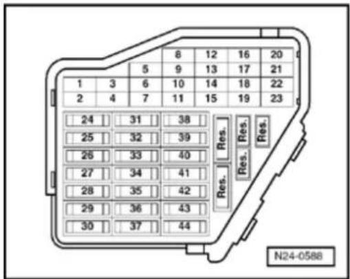
If the engine is to be turned at starter sp without starting:
- Remove fuse 29 from fuse holder.
Note:
Removing fuse 29 interrupts the voltage s u_i the fuel injectors.
- Remove engine cover.
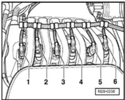
- Disconnect connectors from ignition coils
Note:
Mark connector and component before rem connector.
28-14
Observe following if test and measuring instruments are required during a test drive:
◆ Test and measuring instruments must be secured to rear seat and operated by a 2nd person from this location.
If test and measuring instruments are operated from front passenger's seat and the vehicle is involved in an accident, there is a possibility that the person sitting in this seat may receive serious injuries when the airbag is triggered.
28-15
Test Data, Spark plugs
| Engine code | BDF | |
| Firing order | 1-5-3-6-2-4 | |
| Spark plugs^1) | ||
| VW No. | 1 | |
| Manufacturer's designation | PZF R5D-11 | |
| Electrode gap | max. 1.1 mm | |
| Torque setting | 25 Nm | |
01 000 062 AB
^1) Remove and install spark plugs with plug wrench 3122 B
28-16
Camshaft Position (CMP) Sensor, checking
Note:
Only gold-plated terminals may be used to service the terminals in the Camshaft Position (CMP) Sensor connector.
Special tools, materials and equipment
◆ VAG 1526 or Fluke 83 Hand multimeter 1715 multimeter
◆ VAG 1594 adapter set
◆ VAG 1598/31 test box
♦ Electrical Wiring Diagrams
Test requirements
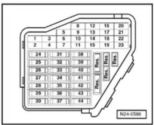

• The fuses must be OK.
• The battery voltage must be at least 11.
- All electrical accessories, e.g. lights and window defroster must be switched off.
- If the vehicle is equipped with air condition it must be turned off.
- Camshaft Position (CMP) Sensor malfu detected by On Board Diagnostic (OBD Page 01-23.
28-17
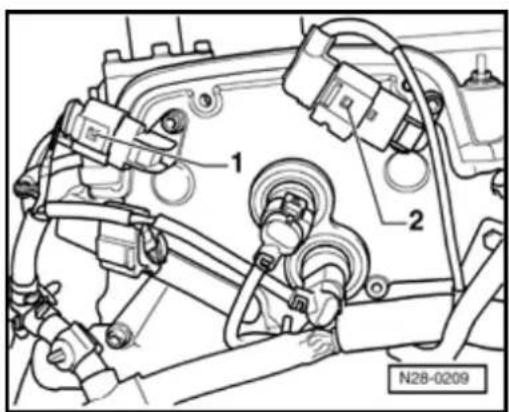
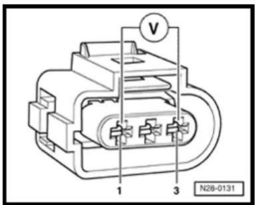
Checking sequence for intake camshaft Camshaft Position (CMP) Sensor -G40-

- Disconnect 3-pin connector from Camshaft Position (CMP) Sensor -G40-, -1-.
Note:
Mark connector and component before disconnecting.

- Connect multimeter to measure voltage at terminals 1 (positive) and 3 (Ground) of Camshaft Position (CMP) Sensor connector using adapter cables from V.A.G 1594.
- Switch on ignition.
Specification: at least 4.5 V - Switch off ignition.
28-18


If no voltage is present:
- Remove wiper arms and cowl panel:
⇒ Repair Manual, Electrical Equipment; Repair Group 92

- Connect VAG 1598/31 test box to control module wiring harness. Engine Control Module (ECM) remains disconnected.

- Check wiring for open circuit between test box and connector referring to Electrical Wiring Diagrams.
terminal 1 and socket 98
terminal 2 and socket 86
terminal 3 and socket 108
Wire resistance: max. 1.5 Ω
28-19
- Additionally check wires for short to one another.
Specification:
If no wiring malfunction is detected and voltage was present between terminals 1 and 3:
- Replace Camshaft Position (CMP) Sensor -G40-→ Page 28-7, item 16.
- Check DTC memory, repair malfunctions if necessary and then erase DTC memory Page 01-23.
- Read readiness code Page 01-146. If DTC memory has been erased or Engine Control Module (ECM) was disconnected from battery positive, readiness code must be generated again Page 01-149.
If no wiring malfunction is detected and no voltage was present between terminals 1 and 3:
- Replace Engine Control Module (ECM) Page 24-173.
- Check DTC memory, repair malfunctions if necessary and then erase DTC memory Page 01-23.
- Erase learned values and adapt Engine Control Module (ECM) again Page 24-182.
28-20
- Read readiness code Page 01-146f memory has been erased or Engine Cont Module (ECM) was disconnected from ba positive, readiness code must be generat again Page 01-149.
Checking sequence for Camshaft Position (CMP) Sensor 2 -G163-
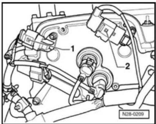

- Disconnect 3-pin connector -2- from Cam Position (CMP) Sensor 2 -G163-.
Note:
Mark connector and component before pull connector off.
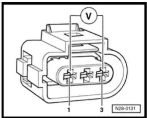

- Connect multimeter to measure voltage at terminals 1 (positive) and 3 (Ground) of Camshaft Position (CMP) Sensor connected using adapter cables from V.A.G 1594.
- Switch on ignition.
Specification: at least 4.5 V
- Switch off ignition.
28-21


If no voltage is present:
- Remove wiper arms and cowl panel:
⇒ Repair Manual, Electrical Equipment; Repair Group 92

- Connect VAG 1598/31 test box to control module wiring harness. Engine Control Module (ECM) remains disconnected.

- Check wiring for open circuit between test box and connector referring to Electrical Wiring Diagrams.
terminal 1 and socket 98
terminal 2 and socket 87
terminal 3 and socket 108
Wire resistance: max. 1.5 Ω
- Additionally check wires for short to one another.
Specification: ∞ Ω
28-22
If no wiring malfunction is detected and voltage was present between terminals 1 and 3:
- Replace Camshaft Position (CMP) Sensor 2 - G163- Page 28-6, item 13.
- Check DTC memory, repair malfunctions if necessary and then erase DTC memory Page 01-23.
- Read readiness code Page 01-146. If DTC memory has been erased or Engine Control Module (ECM) was disconnected from battery positive, readiness code must be generated again Page 01-149.
If no wiring malfunction is detected and no voltage was present between terminals 1 and 3:
- Replace Engine Control Module (ECM) Page 24-173.
- Check DTC memory, repair malfunctions if necessary and then erase DTC memory Page 01-23.
- Erase learned values and adapt Engine Control Module (ECM) again Page 24-182.
- Read readiness code Page 01-146. If DTC memory has been erased or Engine Control Module (ECM) was disconnected from battery positive, readiness code must be generated again Page 01-149.