
RESU16H Prime - Battery LG - Free user manual and instructions
Find the device manual for free RESU16H Prime LG in PDF.

| Product Type | Residential Energy Storage Battery |
| Model | RESU16H Prime |
| Usable Energy | 16 kWh |
| Battery Capacity | 64.1 Ah |
| Voltage Range | 350 – 450 VDC |
| Max. Charging/Discharging Power | 7 kW (20 A @ 350 V) |
| Peak Power (Discharging) | 11 kW for 10 sec |
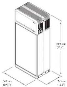
| Dimensions (W × H × D) | 504 mm × 1,086 mm × 295 mm (19.8" × 42.8" × 11.6") |
| Weight | 159 kg (351 lbs) |
| Communication Interfaces | RS485, CAN, Ethernet (via optional RMD) |
| Installation Location | Indoor or Outdoor (standing only, IP55) |
| Operating Temperature | Charge: -10°C to 50°C; Discharge: -20°C to 50°C |
| Recommended Operating Temperature | 15°C to 30°C (59°F to 86°F) |
| Storage Temperature | -30°C to 60°C (short term), -20°C to 45°C (6 months), -20°C to 30°C (12 months) |
| Ingress Protection | IP55 |
| Safety Certifications | UL1642 (cells), IEC 62619, UL1973, CE, RCM |
| Cooling Method | Natural Convection |
| Protection Features | Overvoltage, overcurrent, short-circuit, reverse polarity, temperature protection (internal and inverter interface) |
| User Interface | LED indicators (Power, Charge, Discharge, Fault) |
| Remote Monitoring | Via optional Remote Monitoring Device (RMD) – app and web |
| Maintenance | No regular maintenance required; contact service for faults |
| Package Contents | 2 Battery Modules, Battery Control Unit, mounting brackets, bolts, manual, drill template |
Frequently Asked Questions - RESU16H Prime LG
User questions about RESU16H Prime LG
0 question about this device. Answer the ones you know or ask your own.
Ask a new question about this device
Download the instructions for your Battery in PDF format for free! Find your manual RESU16H Prime - LG and take your electronic device back in hand. On this page are published all the documents necessary for the use of your device. RESU16H Prime by LG.
USER MANUAL RESU16H Prime LG
Installation Manual for RESU16H Prime
LG Energy Solution strongly advises users to exercise due care in following LG Energy Solution's product installation manual. Warranty claims are invalid if damage is caused by human error in a manner inconsistent with the installation manual's instructions.
Version 1.21

LG Energy Solution
Scan QR code to view
[Installation Manual PDF File]
Scan QR code to view
[Installation Video Guide]


The information included in this manual is accurate at the time of publication.
However, this manual is subject to change without prior notice. In addition, the illustrations in this manual are meant only to help explain system configuration concepts and installation instructions.
Please note the images shown are for illustration purposes only.
Contents
1 Safety
1.1 Symbols
1.2 Safety Instructions
1.2.1 General Safety Precautions
1.2.2 Battery Handling Guide
1.2.3 Response to Emergency Situations
1.3 Warning Label
1.4 Qualified Personnel
2 Product Introduction
2.1 Technical Data
2.1.1 Dimensions and Weight
2.1.2 Performance
2.2 Features
2.3 Maintenance
2.4 Packaging Specifications
3 Installation
3.1 Mechanical Requirements
3.1.1 Package Contents
3.1.2 Basic lifting guide
3.1.3 Unboxing the Package
3.1.4 Installation Location
3.1.5 Clearance
3.1.6 Tools & Safety Gear Required
3.1.7 Appearance and Dimensions
3.1.8 System Clearance
3.1.9 Installing the Battery Pack
3.2 Installation process for Remote Monitoring Device (RMD)
3.2.1 Prepare for installation using RMD
3.2.2 Installation via RMD
3.3 Cable Connections
3.3.1 Cable Configuration
3.3.2 Guide for cable connection and setting the DIP switch
3.3.3 Spring Terminal Blocks
4 Commissioning
4.1 LED Indicators
4.2 Powering On the Battery Pack
4.3 Shutting Off the Battery Pack
5 Troubleshooting
5.1 Troubleshooting Overview
5.1.1 Post-Installation Checklist
5.1.2 Troubleshooting Guidelines
6 Uninstallation & Return
6.1 Return/Replacement Instructions
6.1.1 Uninstallation
6.1.2 Contact Information
7. Appendix
7.1 Connection in RESU16H Prime parallel battery system
7.1.1 Setting for communication termination resistor (About Section B)
7.1.2 Power cable (When using a combiner box)
7.2 RMD Applications
7.2.1 Diagnosis check via RMD
7.2.2 BMS, DC/DC and RMD Update via RMD
7.2.3 Installation via RMD for web user
1 Safety
1.1 Symbols


Caution, risk of electric shock
Do not place or install near flammable or explosive materials
Install the product out of reach of children
Read the instruction manual, in its entirety, before starting installation and operation
Heavy weight may cause serious back injuries
Do not dispose of the product with household waste
Recyclable
Disconnect the equipment before carrying out maintenance or repair
Observe precautions for handling electrostatic-sensitive devices
Protective Class 1
Caution, risk of electric shock, energy storage timed discharge.
1.2 Safety Instructions
For safety reasons, installers are responsible for familiarizing themselves with the contents of this document and all warnings before performing installation and servicing.
1.2.1 General Safety Precautions
Over-voltages or wrong wiring can damage the battery pack and cause combustion which can be extremely dangerous.
Any type of product breakdown may lead to a leakage of electrolytes or flammable gas.
Avoid installing the battery pack where flammable materials are stored. Do not install in places where explosive gas or chemicals are present.
During installation of the battery, the utility grid and solar input must be disconnected from the Battery Pack wiring. Wiring must be carried out by qualified personnel.
Battery pack should only be serviced by qualified personnel.
The electronics inside the battery pack are vulnerable to electrostatic discharge.
Be sure to be grounded before handling the battery pack.
Read the label with Warning Symbols and Precautions, which are visible under the Battery Cover (see Section 1.3 Warning Label).
1.2.2 Battery Handling Guide
- Do not expose the battery to an open flame.
- Do not place the product near to highly flammable materials.
- Do not expose or place near water sources such as downspouts or sprinklers.
- Do not store or install the product in direct sunlight.
- Do not install the product in an airtight enclosure or in an area without ventilation.
- Do not install the product in living area of dwelling units or in sleeping units other than within utility closets and storage or utility spaces.
- Store in a cool and dry place. (Do not store in greenhouses or storage areas for hay, straw, chaff, animal feed, fertilizer, vegetables, or fruit products.)
• Store the product on a flat, level surface.
• Store the product out of reach of children and animals.
- Store the product in clean environment, free of dust, dirt and debris.
- Do not disconnect, disassemble or repair the product unqualified personnel. Only qualified personal are to handle, install and service the Product.
- Do not damage the Product by dropping, deforming, impacting, cutting or penetrating with a sharp object. Doing so may cause a fire or leakage of electrolytes.
- Do not touch the product if liquid spills on it. There is a risk of electric shock. Handle the battery wearing insulated gloves.
- Do not step on the product or the product's packaging since the product may be damaged.
- Do not place any foreign objects on top of the Battery Pack and on the cooling fin.
- Do not put the battery pack upside down on the ground.
- Do not connect the power cables at terminal the block in the opposite direction.
• Do not charge or discharge a damaged battery. - If the Product is installed in a garage or carport, ensure there is adequate clearance from vehicles.
- The battery pack has been certified IP55 and can be installed indoors as well as outdoors. However, if installed outdoors, do not allow the battery pack to be exposed to direct sunlight or water sources, as they may cause:
- Power limitation phenomena in the battery (with a resulting decrease in energy production by the system).
- Premature wear of the electrical/electromechanical and mechanical components.
- Reduction in performance, performance warranty and possible damage of the battery
• Only use the product with a LGES-authorized inverter.
For a list of compatible inverters, visit the LG ESS Battery Website by the URL below and check the 'Home Battery' > 'Product Info' menu.
https://www.lgessbattery.com/us (in case of North America)
https://www.lgessbattery.com/au (in case of Australia)
https://www.lgessbattery.com/eu (in case of all EU-countries in general)
https://www.lgessbattery.com/de (in case of Germany)
https://www.lgessbattery.com/it (in case of Italy)
https://www.lgessbattery.com/es (in case of Spain) - Do not connect any AC conductors or photovoltaic conductors directly to the battery pack. These are only to be connected to the inverter.
1.2.3 Response to Emergency Situations
The Product includes internal fault mechanisms designed to prevent failures and subsequent risk hazards. However, LG Energy Solution cannot guarantee safety performance of the Product is ever exposed to abuse, damage or negligence.
- If a user happens to be exposed to the internal materials of the battery cell due to damage on the outer casing, the following actions are recommended. In case of inhalation: Leave the contaminated area immediately and seek medical attention.
In case of contact with eyes: Rinse eyes with running water for 15 minutes and seek medical attention.
In case of contact with skin: Wash the contacted area with soap thoroughly and seek medical attention.
In case of ingestion: Induce vomiting and seek medical attention.
If a fire breaks out at the location where the battery pack is installed, perform the following countermeasures.
• Utilize fire-extinguishing media
A respirator is not required during normal operation.
Use an FM-200 or CO2 extinguisher for battery fires.
Use an ABC fire extinguisher if the fire is not from the battery and has not yet spread to it.
• Follow proper fire-fighting instructions
- If a fire occurs when charging batteries, provided it is safe to do so, disconnect the battery pack circuit breaker to shut off the power charge.
- If the battery pack is not on fire yet, extinguish the fire before the battery pack catches fire preferably with water.
- If the battery pack is on fire, do not try to extinguish it, and evacuate people from the premises immediately.
WARNING
There may be a possible explosion when batteries are heated above 150^ C. When a battery pack is burning, it will leak poisonous gases. Do not approach it.
• Effective ways to deal with accidents
On land: Place the damaged battery into a segregated place and call your local fire department or service engineer.
In water: Stay out of the water and do not touch anything if any part of the battery, inverter, or wiring is submerged.
Do not use the submerged battery again. Contact your service engineer for assistance.
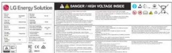
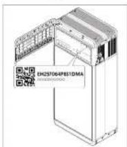
1.3 Warning Label
Product/warning label and Battery Control Unit's traceability label are behind the front cover. The front cover opens by turning the front cover handle counterclockwise. Battery Modules' traceability labels are attached to the side of the Battery Modules.
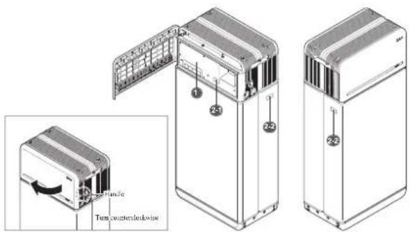
- Product/Warning Label
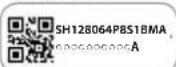
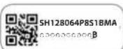
2. Traccability label
2-1. Battery Control Unit 2-2. Battery Module

This guide for the tasks and procedures described herein is intended for use by skilled staff only. A skilled staff is defined as a trained and qualified electrician or installer who has all of the following skills and experience:
- Knowledge of the functional principles and operation of on-grid and off -grid (backup) systems
- Knowledge of the dangers and risks associated with installing and using electrical devices and acceptable mitigation methods
• Knowledge of the installation of electrical devices - Knowledge of and adherence to this guide and all safety precautions and best practices
• Qualifi cation specifi ed in battery warranty fi le
: RESU-certification in the battery website
: Knowledge of local installation standards
: Electrical license for battery installation required by the country or state
• Repair the battery by disassembly is possible only at the LG Service Center or by a person who is specially authorized separately from the installation qualification
2 Product Introduction
2.1 Technical Data
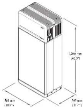
2.1.1 Dimensions and Weight
| RESU16II Prime | |
| Part Number EII257064P8S1 | |
| Width 504 mm (19.8") | |
| Height 1,086 mm (42.8") | |
| Depth 295 mm (11.6") | |
| Weight ^1) | 159 kg (351 lbs) |
1) Battery pack weights may vary slightly.
2.1.2 Performance
| Electrical Characteristics | |
| Usable Energy11 | 16 kWh |
| Battery Capacity | 64.1 Ah |
| Voltage Range | 350 to 450 VDC |
| Absolute Max. Voltage | 595 VDC |
| Max. Current (charging/discharging) | 20A @ 350V |
| Max. Power (charging/discharging) | 7 kW |
| Peak Power7 (only discharging) | 11 kW for 10 sec. |
| Peak Current (only discharging) | 32.8A for 10 sec. |
| Communication Interface | RS485/ CAN |
| DC Disconnect | Circuit Breaker |
| Connection Method | Spring Type Connector |
| User Interface | LEDs for Normal and Fault Operation |
| Operating Conditions | |
| Installation Location | Indoor/Outdoor (Standing Only) |
| Operating Temperature | charge 14^ to 122^ ( -10^ to 50^ )discharge -4^ to 122^ ( -20^ to 50^ ) |
| Operating Temperature (Recommended) | 59^ to 86^ ( 15^ to 30^ ) |
| Storage Temperature | -22^ to 140^ ( -30^ to 60^ ), acceptable for 7 days in total -4^ to 113^ ( -20^ to 45^ ), acceptable for the fi rst 6 months -4^ to 86^ ( -20^ to 30^ ), acceptable for months 7~12 |
| Humidity | 5% to 95% |
| Altitude | Max. 6,562 ft (2,000 m) |
| Cooling Strategy | Natural Convection |
| Certifi cation | ||
| Safety | Cell | UL1642 |
| Battery | CE / RCM / IEC 62619 / UL1973 / IEC62477-1 | |
| Pack | ||
| Emissions | FCC | |
| Hazardous Materials Classification | Class 9 | |
| Transportation | UN38.3 | |
| Ingress Rating | IP55 | |
※ Test Conditions: Temperature 25°C/77°F, at the beginning of life.
※ Energy is measured under specific conditions from LG Energy Solution (0.3CPCV/0.3CP).
1) Value for battery pack only. Maximal usable energy at the AC output may vary by condition, such as inverter efficiency, configuration and temperature.
2) Peak current excludes repeated short duration (less than 10 sec. of current pattern).
1. Short Circuit Current/Duration
Short Circuit Current 1.616 kA
Duration 0.44 ms
2. Arc Flash Protection Calculations
In order to protect personnel from the possibility of getting injured by an arc flash hazard, Arc flash calculation of the battery system is estimated with the Incident Energy Calculations refer to Annex D of NFPA 70E.
Battery System Voltage 288.4V
Battery System Internal Resistance 0.06Ω
Bolted Fault Current 1.616 kA
Arcing Current 0.808 kA
Clearing Time 371 us
Arc Flash Incident Energy 0.000132 Cal/cm
Working Distance 450 mm (18 inches)
Battery system installers must wear PPE (Personal Protective Equipment) according to NFPA 70E Article 130.

WARNING
- When installing the battery system, the worker shall wear arc-rated clothing in every occasions and places to protect him/her from any possible exposure to an electric arc flash.
- The arc-rated clothing worn by the worker must assure the worker's movement and visibility while covering all ignitable clothing.
- The worker shall always wear the non-conductive safety helmet every occasions and places to protect him/her from any danger of head injury from electric shock or burns due to the contact with energized electrical conductors or circuit parts resulting from electrical explosion.
- The worker shall wear non-conductive protective equipment for the face, neck, and chin at every occasion and location to protect him/her from danger of injury from exposure to electric arcs or flashes resulting from an electrical explosion.
- The worker shall wear non-conductive protective equipment for the eyes at every occasion and location to protect him/her from any danger of injury from electric ares or flashes resulting from an electrical explosion.
- The worker shall wear hearing protection within the arc flash boundary.
- The worker shall wear heavy-duty leather gloves or arc-rated gloves, satisfying the following regulation level, for arc flash protection. In the case of wearing the rubber gloves for the shock protection, he/she shall wear additional leather protectors above the gloves.
- The worker shall wear heavy-duty leather footwear or dielectric footwear or both to provide some arc flash protection.
- The worker shall inspect arc-rated apparel before every use. Work clothing or arc flash suits that are contaminated or damaged to the extent, impairing the protective qualities, shall not be used. Protective items that become contaminated with grease, oil, flammable liquids or combustible materials shall not be used.
- The garment manufacturer's instructions for care and maintenance of arc-rated apparel shall be followed.
- Arc-rated apparel shall be stored in a manner that prevents physical damage; damage from moisture, dust, or other deteriorating agents; or contamination from flammable or combustible materials.
2.2 Features
- Compact energy storage unit for domestic photovoltaic system compatibility
- Residential 400V DC battery pack system: Daily cycle and emergency back up capability.
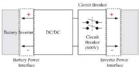
flowchart
graph LR
    A["Battery Inverter"] --> B["DC/DC"]
    B --> C["Circuit Breaker (600V)"]
    C --> D["Inverter Power Interface"]
    style A fill:#f9f,stroke:#333
    style B fill:#ccf,stroke:#333
    style C fill:#cfc,stroke:#333
    style D fill:#fcc,stroke:#333
• Protection devices included as follows:
- Inverter Power Interface for protection against overvoltage, overcurrent, external short-circuit, reverse polarity, inrush current and over temp.
- Battery Power Interface for protection against internal short-circuit, overvoltage, overcurrent, over temp and undervoltage.
• Flexible installation: Indoors or Outdoors
2.3 Maintenance
RESU16H Prime does not require maintenance during normal operation if properly installed per the installation manual. In the event of fault, contact the regional service center.
2.4 Packaging Specifications
| Category | Contents | ||||
| Size (L×W×II) | 750 mm(29.5") | 985 mm(38.8") | 885 mm(34.8") | Outer Size | |
| Qty/Box (ca) | 1 | ||||
| Packaging Materials | Box | Corrugated Cardboard | Disposable | ||
| Inner | EPS | Disposable | |||
| Pallet | Wood | Disposable | |||
| Weight | Product | 159 kg (350.5 lbs) | 1 pack/box(Battery Module (x2) + Battery Control Unit - enclosed items) | ||
| Packaging 30 kg (66.1 lbs) | Pallet (8.7kg) + Box (21.3kg) | ||||
| Gross | 189 kg (416.7 lbs) | Product + Packaging | |||
3 Installation
3.1 Mechanical Requirements
3.1.1 Package Contents
The following items are included in the package:
Battery Module A&B
Battery Control Unit
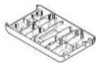
Module Connect Plate
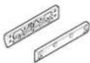
Module Support BRKT (x2)
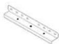
Standing Bracket 1 & 2
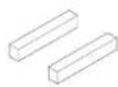
Spacer (x2)

M6 x L10 Flange
Bolt (x18)
M5 × L200 Long Flange Bolt (x6)

3/4"-1" Adapter (x2)
Cap (x2)
Manual

Drill template
Cable ties
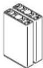
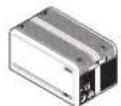
3.1.2 Basic lifting guide
Refer to below guide for lifting and carrying the Battery Control Unit and Battery Modules during installation.
Handling position
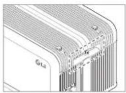
natural_image
Cross-sectional diagram of a layered electronic component with no visible text or symbols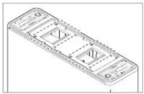
natural_image
Isometric line drawing of a rectangular electronic device with internal components and mounting holes (no text or symbols)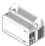
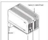
natural_image
Isometric line drawing of a rectangular battery or casing with internal components (no text or symbols)Battery Control Unit Battery Module (1 installer)
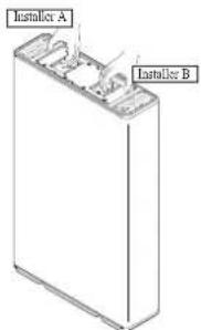
Battery Module (2 installers)
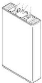
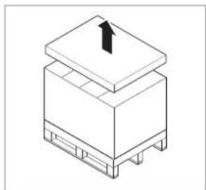
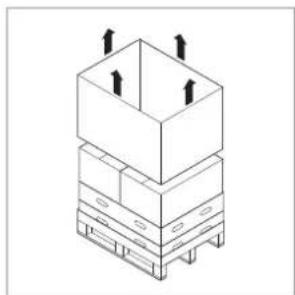
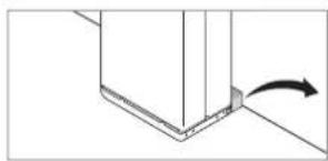
3.1.3 Unboxing the Package
natural_image
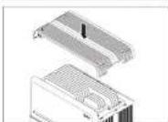
Isometric line drawing of a mechanical component with a black upward arrow on top (no text or symbols)- Cut the packing strap and remove the top lid.
natural_image
Isometric line drawing of a stacked storage unit with upward arrows indicating flow or movement (no text or symbols)- Remove the sleeve.
natural_image
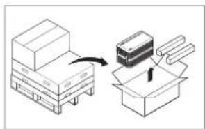
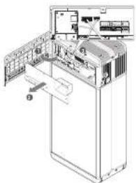
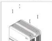
Diagram showing a box being processed with a device, no text or symbols present- Pull out the Battery Control Unit, and the Spacers (x2).
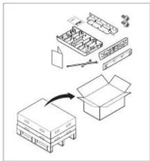
- Pull out the bundled items, including the Module Connecting Plate.
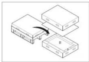
natural_image
Diagram of a device with three stacked components and an arrow indicating a transformation or assembly (no text or symbols present)- Pull out Battery Module B.
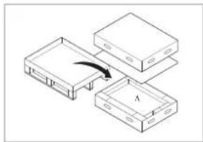
natural_image
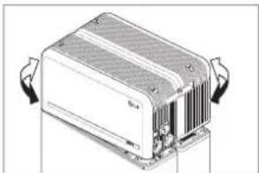
Diagram showing three rectangular electronic components with a curved arrow indicating rotation or movement, no text or symbols present.- Pull out Battery Module A.
CAUTION
According to regional regulations, several people may be required for moving equipment.
3.1.4 Installation Location
Requirements:
• There must be no highly flammable or explosive materials nearby.
- The ambient temperature should be within the range of -4^ to 122^ (-20°C to 50^ ).
- The battery pack must be installed on flat leveled ground that can support its weight.
- Product shall be installed indoors (ex. in a basement or a garage) or outdoors under an cave and out of direct sunlight.
Recommendations:
• The building should be designed to withstand earthquakes.
• The area should be waterproof and properly ventilated. (IP55)
- The product should be installed out of reach of children and animals.
CAUTION
If the ambient temperature is outside operating range, the battery pack will stop operating to protect itself. The optimal temperature range for the battery pack to operate is from 59°F to 86°F (15°C to 30°C).
Frequent exposure to harsh temperatures may deteriorate the performance and life of the battery pack.
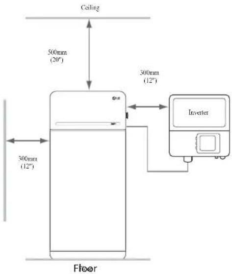
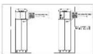
3.1.5 Clearance
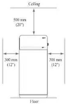
- Recommended clearances for the left, right and top of the product are shown in the figure for the proper ventilation and installer convenience.
3.1.6 Tools & Safety Gear Required
- Tools
The following tools are required to install the battery pack :
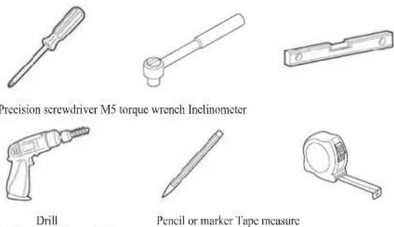
Precision screwdriver M5 torque wrench Inclinometer
(min. diameter 10 mm, 0.4")
Pencil or marker Tape measure
* The fasteners are needed for fixing the bracket on the wall
• Safety Gear for Personal Protection
It is required to wear the following safety gears when handling the battery pack.

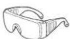
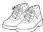
Insulated gloves Safety goggles Safety shoes
3.1.7 Appearance and Dimensions
- Appearance
Proper handling and care are recommended as disassembly, change of color, scratches, leakage of liquid, and stains may influence the economic value of the battery pack.
• Pack appearance and dimensions
• Color and materials
- Battery Module front/rear case: metallic gray, steel
- Battery Control Unit cover & Module Connect Plate: metallic gray, aluminum
- LED cover: black, plastic
3.1.8 System Clearance
The battery requires adequate clearance for installation, cabling, and airflow. The minimum clearance for system configuration is provided below. The cable connecting between battery pack and inverter should be in accordance with the installation guide manual of the inverter.
NOTE
An external DC isolator may be installed within the clearance zone. Minimum clearances may be greater according to local regulations.
3.1.9 Installing the Battery Pack

CAUTION
Make sure that the inverter AC and DC disconnects are turned off before connecting the power cable to the battery pack.
Install the battery pack through the following steps:
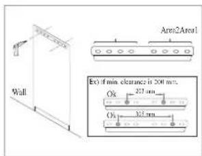
- Place the Drill template to the wall where the battery pack will be installed. After that, drill holes on the position marked on the Drill template.
* Recommended fastener count: 1(Area1)/1(Area2)
* Recommended fastener diameter/length: 10mm/40mm Min.
* Fastener separation should observe the regional building code.
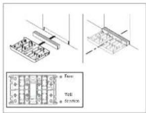
- Place a spacer to the position marked on the Drill template. After that, place the Module connect plate in contact with the Spacer and align center lines.
* Pay attention to the direction of the Spacer. Refer to left image for correct orientation.
* Do not use anchor bolts to fix the Module connect plate to the floor.
* Be careful not to damage the aluminum foil attached on the bottom of Module connect plate during handling.
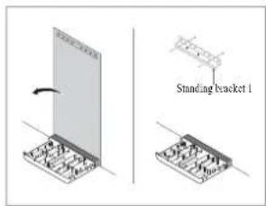
- Remove the Drill template. Then pre-tighten the fasteners on the Standing Bracket 1.
* The fasteners will be fully tightened in a later step.
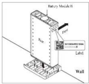
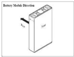
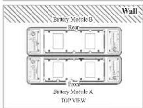
- Place Battery Module B on the rear side of Module Connect plate.
* The side without bolts is the front of the Battery Module.
* Check the label to confirm the battery pack is of B. Label is attached on the left side of Battery Module.
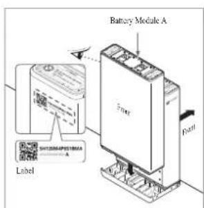
- Place Battery Module A on the front side of Module Connect plate. The Rear side of each Battery Module should face each other. After that, remove the Spacer between the wall and Battery Module.
* Check the label to confirm the Battery pack is of A. Label is attached on the left side of Battery Module.
natural_image
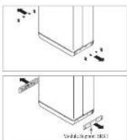
Pure mechanical diagram showing a bracket with an arrow indicating motion (no text or symbols)- Assemble Module Support BRKTs using 6 bolts cach.
* Tighten the M6 Flange Bolts (x12) with a torque of 5N·m.
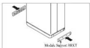
natural_image
Pure diagram of a structural component with no text, numbers, or symbols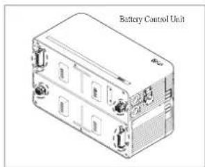
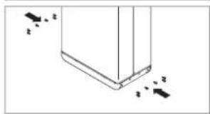
- Remove bubble wrap from connectors of Battery Control Unit and the warning label of Battery Modules.
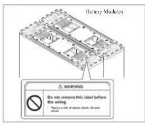
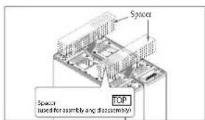
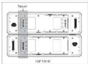
- Place the spacers on the position marked with label on Battery Modules.
natural_image
Technical line drawing of a mechanical or electronic component with directional arrows indicating movement (no text or symbols)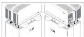
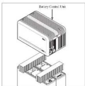
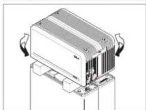
- Place the Battery Control Unit on top of the spacers, and align with the Battery Module.
* Be careful not to break the connector between the spacers and the Battery Control Unit.
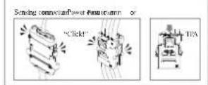
- Connect the power and sensor connectors on the right and left sides (2 each). Assemble the connectors until you hear a "Click". After that, lock the power connector by pressing TPA (Terminal Position Assurance).
natural_image
Illustration of a mechanical or electronic device with cooling fins and mounting base (no visible text or symbols)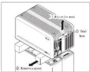
natural_image
Illustration of a rectangular electronic device with heat sinks and ventilation grilles (no text or symbols)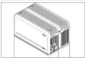
natural_image
Illustration of a rectangular electronic device with ventilation grilles and cooling fins (no text or symbols visible)-
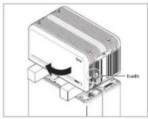
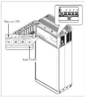
Check the operation of the battery pack by following the steps below. 1) Hold and turn the handle counterclockwise.
2) Open the front cover and turn on the circuit breaker switch.
3) If there are no problems with the assembly process or the product itself, the LED power indicator will turn on. Sixty (60) seconds later, the LED fault indicator will blink (due to a lack of communication with the inverter, not due to a product defect).
4) Turn off the Circuit Breaker switch. Then, close the front cover and turn the handle counterclockwise.
* If you experience any problems at this stage, go to Section 5 Troubleshooting. -
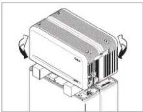
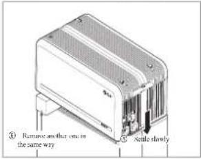
Double-check the alignment of the Battery Control Unit.
-
Remove one spacer by lifting one side of the Battery Control Unit. After that, remove the other spacer in the same way.
* Be careful not to pull on the cables by lifting the Battery Control Unit too high. Doing so may cause damage to the cables or cause the unit to disconnect.
* Before setting down the Battery Control Unit, the cable connection should be checked once more.
- Realign the Battery Control Unit.
natural_image
Diagram of a heat exchanger unit with cooling fins and ventilation slots (no text or labels)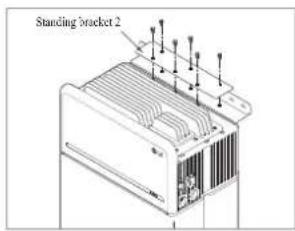
natural_image
Technical line drawing of a server or rack unit with ventilation grilles and cooling fins (no text or symbols)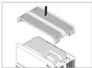
natural_image
Technical illustration of a heat exchanger or cooling unit with cooling fins and heat sinks (no text or symbols)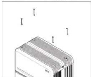
natural_image
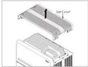
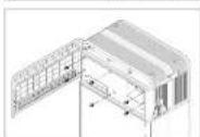
Diagram of a heat exchanger or cooling unit with mounting holes and cooling fins (no text or symbols)-
Loosen 4 bolts and remove the Top Cover.
-
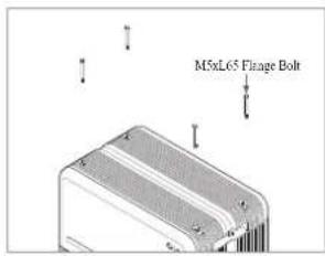
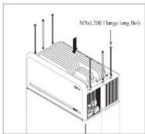
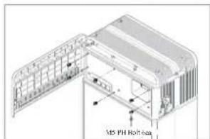
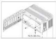
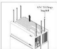
Tighten six (6) long flange bolts with a torque of 5N·m.
* While assembling, open the front cover and check that all M5 Flange long bolts are placed accordingly.
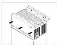
-
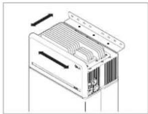
Move the Battery pack to set the right position for assembly of the Standing bracket.
-
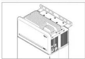
Pre-tighten six (6) M6 bolts to assemble the Standing Bracket 2 on Battery Control Unit and the Standing Bracket 1. After that, fully tighten all bolts and fasteners on the Standing Bracket 1 and the Standing Bracket 2.
* Tightening torque for the M6 bolts is 5N·m.
- Re-attach the top cover.
* Tighten the M5xL65 Flange Bolt (4ca) with a torque of 5N·m.
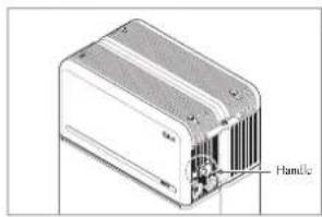
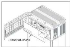
- Open the front cover.
* Hold the handle and turn it counterclockwise.
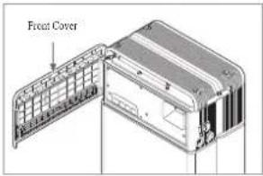
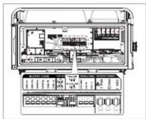
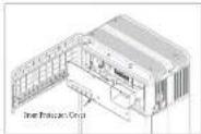
- Loosen 6 bolts and remove the Front Protection Cover.
* Be careful not to drop the bolts into the pack at this stage.
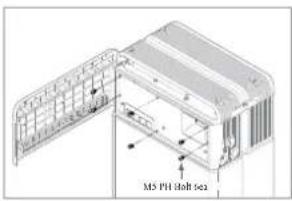
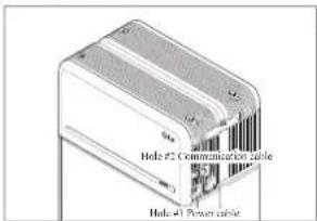
- Assemble the adapter or cap according to regional regulations. Insert the RMD ethernet cable through I Hole #2 and connect the cable. Then proceed to Section 3.2 Installation for Remote Monitoring Device (RMD).
natural_image
Illustration of a rectangular electronic device with labeled ports (no text or symbols on the body)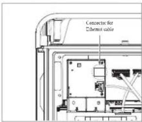
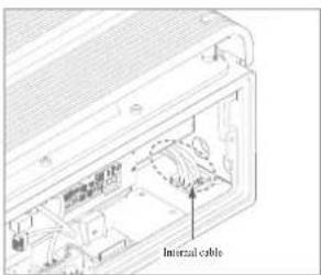
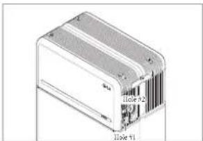
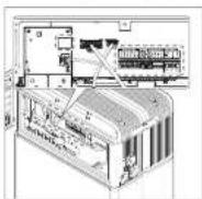
- Assemble the adapter or cap according to regional regulations. Then insert the power and communication cables through the holes from outside of the pack.
* Arrange the internal cable as required to avoid blocking the holes for external cables.
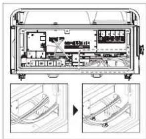
- Connect the cables according to their application.
* Refer to Section 3.3 Cable Connections.
natural_image
Technical diagram of an electronic device showing internal components and two views of a cable or connector (no text or labels present)- Arrange the power cables and communication cables separately using cable ties.
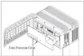
- Re-attach the Front Protection Cover with M5 PH bolt 6ea.
natural_image
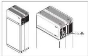
Technical illustration of two rectangular electronic components with labeled handle (no text or symbols beyond label)- Close the front cover.
* Hold the handle and turn it clockwise.
* Make sure the Front Cover is closed.
3.2 Installation process for Remote Monitoring Device (RMD)
Remote monitoring device (RMD) is a remote device that can install and monitor a battery pack through App. and web.
3.2.1 Prepare for installation using RMD
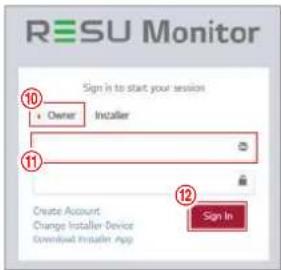
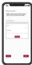
3.2.1.1 Installer Sign In
3.2.1.1.1 Visit https://resumonitor.lgensol.com
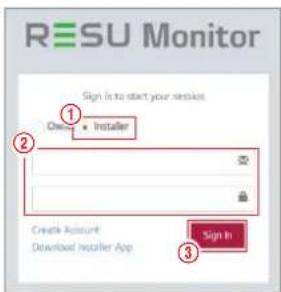
- Select the "Installer" option.
- Enter your ID and Password.
- Click the "Sign In" button.
If you don't have your account, please visit LG ESS Battery website and make an account. https://www.lgessbattery.com/us (in case of North America) https://www.lgessbattery.com/au (in case of Australia) https://www.lgessbattery.com/eu (in case of all EU-countries in general) https://www.lgessbattery.com/de (in case of Germany) https://www.lgessbattery.com/it (in case of Italy) https://www.lgcssbattery.com/cs (in case of Spain)
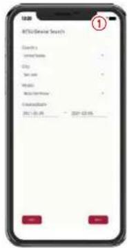
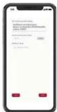
3.2.1.2 Obtaining IoT Hub String
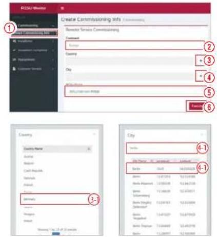
- Select "Commissioning" → "Create Commissioning Info" on the left sidebar to access the commissioning information creation screen.
- Select a continent (ex. Europe, North America, Oceania).
- Click the "+" button to the right of "Country", and double-click the appropriate country from the drop-down list.
- Click the "+" button to the right of "City", and enter two (2) or more letters in the search field. Find the appropriate country and double-click it.
- Select the appropriate RESU Model.
- Click the "Execute" button to complete product registration. The device connection string information will sent to the account e-mail address.
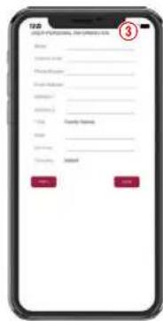
3.2.1.3 User Registration
3.2.1.3.1 Visit https://resumonitor.lgensol.com

3.2.1.3.2 Create an Owner account.
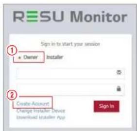
- Select the "Owner" option.
-
Select "Create Account".
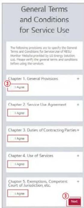
-
Review the General Data Protection Regulation (Privacy Policy) and check "I Agree" to indicate consent. Click the "Next" button to proceed to the next step.
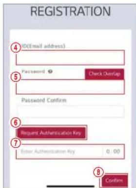
-
After entering your ID (e-mail address), click the "Check Overlap" button to check for duplicates.
- Enter your new password and confirm the same password in the next field. Password requirements: 10 to 25 characters long, including letters, numbers, and special characters (!, #, \$, %, ^, &, -, =).
- Click the "Request Authentication Key" button to receive your authentication key at the e-mail address you provided.
- Enter your authentication key within 3 minutes to verify your account.
- Click the "Confir rm" button.
-
Select the "Owner" option.
-
Enter your ID and Password.
-
Click the "Sign In" button.
3.2.2 Installation via RMD
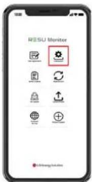
Click the link on the RESU Monitor website to download the APK file of the 'RESU Installer' App.

NOTE
Depending on the device, 'RESU Installer' App may not work.
'RESU Installer' App is available in the version of the software as follows;
- Android OS: Pic(9.0) or higher
※ For iOS users, please Refer to Section 7.2.3. Installation via RMD for web user.
3.2.2.1 Powering On the Product
To proceed with product installation, turn on the product.
* Open the front cover and turn on the circuit breaker switch.
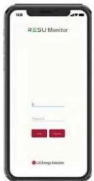
3.2.2.2 RMD App Log-in
When you run the app, you are the first to log in. (It is assumed that you have created an account in advance.)
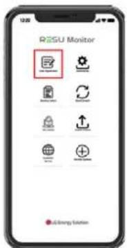
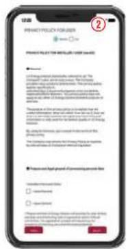
3.2.2.3 User Agreement
- Search the product which you will install.
- Get the agreement of privacy policy for the customer.
- If the customer agrees the privacy policy, have customer's personal information.
3.2.2.4 RMD Wi-Fi Direct Connection
In order to install using RMD, you must first use RMD's Wi-Fi direct connection.
For the RMD's Wi-Fi direct connection, see below.
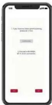
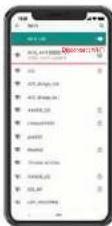
Search and access the SSID of the RMD AP from a device capable of supporting WLAN Station functions (ex. smartphone).
RMD SSID has a structure of "RESU_(or RMD) + RMD WLAN STM MAC ADDRESS". For the devices below, the SSID of the RMD SoftAP is "RESU_44CBXXXC14F(or RMD44CBXXXC14F)". The password is 12345678(changeable).
When Wi-Fi connection is complete, click the "Next" button.
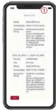
3.2.2.5 QR Code Scan
The QR code scanning method is as follows.
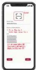
When the QR code registration is complete, click the "Next" button.
If the scanned serial number matches the actual serial number, it will proceed to the next section.
There are three (3) QR codes: Battery Control Unit, Battery Module A, and Battery Module B.
- Battery Control Unit QR Code
- Battery Module QR Code
3.2.2.6 External Internet Connection
(※ If the end user does not wish to use an external internet connection, simply press the
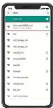
3.2.2.4.2 Wi-Fi Connection
If you are using an ethernet connection and do not wish to use Wi-Fi, simply click the "Next" button.
Scan AP(①): Wi-Fi-networks currently available for connection is displayed in ②. SSID(③): Enter the name of the Wi-Fi-network to connect(You can enter it manually without going through ①).
Password: Enter the password of the Wi-Fi-networks to connect.
When internet connection is successful, click the "New" button.
* In case the WLAN connection is unstable, enhance the signal by using a WLAN repeater.
3.2.2.7 RMD Configuration Setup
Proof with the below RMD configuration settings.
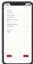
Continent: Select your continent
Time Zone: Hour Select your time zone
RMD Power Save Timer: OFF(default)
2013 Canadian Media: Kansai Media Solutions
3.2.2.8 Server Connection and Battery Status Check
In Hub Connection String: Enter the unique string provided to you in order to access the
Aure in! Thin [cloud server].
HostName=emashub.azure-devices.net,DeviceId=XXXX;SharedAccessKey=0000=
* For more information on how to obtain strings, refer to Section 3.2.1.2 Obtaining IoT Hub String.
Server Connection Check: Check the server connection.
Battery Status: Check if the product has diagnosed any issues.
When the server connection is complete, click the "Next" button.
3.2.2.9 RMD Wi-Fi Disconnection
Disable Wi-Fi in the same way that you connected Wi-Fi in Section 3.2.2.4 RMD Wi-Fi Direct Connection
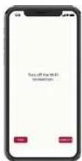
When the server connection is complete, click the "Complete" button.
3.3 Cable Connections
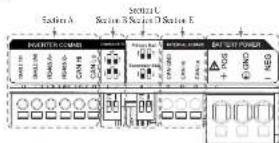
3.3.1 Cable Configuration
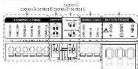
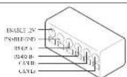
- Section A: Inverter communication parts including CAN/RS485 and enable lines
- Section B: DIP switch for setting communication termination resistor.
- Section C: DIP switch for setting primary-secondary packs.
- Section D: Do not connect the internal communication ports
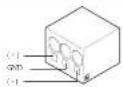
- Section E: Battery power ports including positive/negative pole and ground (POS: power terminal plus, NEG: power terminal minus, GND: ground)
3.3.2 Guide for cable connection and setting the DIP switch
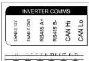
- Section A: Inverter communication
ports
a) First, enclose the enable ground
WIRE TO TERMINAL 2,
b) Connect the enable 12V positive
line to Terminal
c) Select the method that matches the
inverter communication method
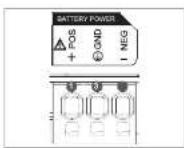
- Section B. Battery power port
a) Connect the ground wire to terminal 2.
b) Connect the negative line of the power cable to Terminal 1.
c) Connect the positive line of the
※ Refer to 3.3.3 Spring Terminal Blocks when choosing the battery power cable and cable sheath for peeling
When you install two packs, refer to the appendix about power cable.
3.3.3 Spring Terminal Blocks
- Power terminal block
• Max. cable length: 10 m (35 ft)
• Cable type: 8mm* (S AWG)
- DC 600V insulated
- Planning
• Phoenix contact
• PCB terminal block SPT
S/3-H-7.5-ZB
P/N:1719202
- Communication terminal block
• Max. cable length: 10 m (35 ft)
- Cable type: 0.2\~1.5mm² (18-22AWG)
- Pinnig
+ Phoenix contact
• PCB terminal block SPT 2,5:6-H-5.0
· P/N: 199101
36 Peel cable sheaths (15 mm for the power terminal cable and 10 mm for the communication terminal cable).
NOTE
Check all cable are firmly in place. Loose power cables can cause arcing and may damage the battery and/or inverter.
4 Commissioning
4.1 LED Indicators
The LED indicators on the front of the battery parks show its operational state as follows:

| LED 1(Power) | LED 2(Charge) | LED 3(Discharge) | LED 4(Fault) | Status | |
| Power on (hit) | |||||
| R | # | ||||
| -- Charge | |||||
| -- Dachings | |||||
| Fault 1 | Nominal | ||||
| Fault 2 | |||||
| (Every 10 c) | --- | Power-saving | |||
| Power Off | |||||
| (Qutely) | --- | Updring | FW Update | ||
| Update Complete | |||||
| Update Failed | |||||
There are four LED indicators on the front of the battery packs to show its operating status.
- Power On(Init): Initialization for operating the battery
- Ready: Battery is ready for operating normally.
- Charge: Battery pack is charging.
- Discharge: Battery pack is discharging.
- Fault : Battery pack is warning state. Fault1 is blinking. Fault 2 is continuous. See Section 5 Troubleshooting guide for detail condition.
- Power saving: Battery stay in minimum self consumption power mode.
- FW update: Battery is in update sequence. See the detail LTD indication about Updating, Update complete. Update failed.
4.2 Damping On the Bottom Book
5 Troubleshooting
5.1 Troubleshooting Overview
Checks the LED indicators on the front to determine the state of the battery pack. A fault state is triggered when certain conditions like voltage or temperature are beyond design limitations. The battery pack's HMS periodically reports its operating state to the inverter.
When the battery pack falls outside of prescribed limits, it enters a fault state. When a fault is reported, the inverter immediately terminates operation.
Use the monitoring software on the inverters to identify what caused the fault state. The possible warning messages see as follows:
- Bartery Overvoltage
- Battery Undervillage
- Barley Over Temperature
- Battery Under Temperature
• Battery Discharge Overcurrent
- Battery Charge Overcurrent
- Bartery Overcharge Power Limit
- Battery Overdischarge Power Limit
• BMS Internal Error
- External Communication Error
• Internal Communication Force
• Battery Cell Deviation Voltage
- Bartery Pack Undervoltage
• Battery Urgent Undervoltage
The fault state is cleared when the battery pack resumes normal operation. If battery pack is not working correctly and the issue persists, contact a qualified staff, installer or LG Energy Solution regional contact service point.
NOTE
For serious warnings, if no proper conective action is taken by the inverter, the battery pack's circuit breaker will automatically trip to protect itself.
CAUTION
If the battery pack or the inverter indicates FAULT or fails to operate, contact LG Energy Solution regional contact point or your distributor immediately.
5.1.1 Post-Installation Checklist
| YesNo | ||
| 1. Visually check if the wiring matches the installation manual. (Section 3.3 Cable Connections.) | ○ | ○ |
| 2. The circuit breaker is ON. | ○ | ○ |
| 3. The battery LED power indicator is ON. | ○ | ○ |
| 4. The interior power is ON. | ○ | ○ |
5.1.2 Troubleshooting Guidelines
If the battery LED power indicator is OFF
-
Durn off the circuit breaker:
-
Turn off the inverter: Verify there is no power at the battery connection.
-
Unplug all the wires and reconnect. Check that the wiring on the battery has been done correctly. Refer to Section 3.3 Cable Connections.
-
Turn on the circuit breaker.
-
Tum on the inverter.
-
If the LED power indicator is still OFF, turn off the circuit breaker.
-
Disconnect the power cable connector.
-
Contact I.G Energy Solution regional contact point
1) Consider the inverter manufacturer.
2) Refer to the inverter installation manual or troubleshooting guidelines.
3) Refer to the Installation manual (3.2 Cable Connections) for the location of the battery and the Curee Breaker.
If the LED power indicator is ON, but the battery is not charging or discharging
-
Update both the inverter and battery firmware versions. Refer to the inverter's troubleshooting guide for instructions.
-
Check the inverter's battery settings. Refer to the inverter's troubleshooting guide for battery setup instructions.
-
If the battery is recognized, inverter setup has been completed successfully.
-
If the issue persists:
4-1. Turn off the circuit breaker.
4-2. Turn off the inverter. Verify there is no power at the battery connection.
4-3. Unplug all wires and reconnect. Check that the wiring on the battery has been done correctly. Refer to Section 3.3 Cable Connections.
4-4. Turn on the circuit breaker.
-
If the battery setup is correct, but the battery is still non-operational, turn off the circuit breaker
-
Contact LG Energy Solution regional service contact point
| LED Status Action | |
| Power on | |
| Charging | |
| Discharging | |
If the LED fault indicator is ON
- Check if the inverter recognizes the battery. Refer to the inverter's troubleshooting guide for battery system instructions.
6 Uninstallation & Return
6.1 Return/Replacement Instructions
6.1.1 Uninstallation
Uninstall the battery pack in the following order:
- Switch the inverter OFF before beginning uninstallation of the battery pack.
- Switch circuit breaker OTT and make sure it is in the OFF position.
-
Open the front cover, lesson 6 bolts and remove the Front Protection Cover
-
Disconnect the cables.
-
Re-attach the Front Protection Cover with M5 PH bolt Gas
- Lnosen six (6) M6 bolts and disassemble Standing Bracket #2 (1 at). Then move the battery pack off the wall and remove Standing Bracket #1 from the wall.
- Loosen six (6) long bolts.
- Re-attach the top cover. * Tighten the M5x1.65 Flange Bult (4mm) with a torque of 5N·m.
- Place the first spacer on top of the Battery Modules.
ENGLISH
* Be careful not to pull the cables light by lifting the Battery Control Unit excessively. It may damage the cables or disassembly of connector.
6.1.2 Contact Information
Damaged batteries are dangerous and must be handled with extreme caution. They are not for use and may pose a danger to people or property. If the battery pack seems to be damaged, contact I.G. Energy Solvrian regional contact point or your distributor. Use the contacts below for technical assistance. These phone numbers are available only during business hours on weekdays.
| Service Contacts | |
| http://www.other Rajins | Address 29, Gwahakstuneyo-San, Olkso-myeon, Heungshok-pu, Cheongjin-ji, Chungchenophuk-do, South Korea |
| Email:esservice@jgentsol.com | |
| Address 19481 San Jose Ave City of Industry, CA 91748, U.S.A | |
| US | Telephone 1 558 375 5041 |
| Email:heighjetsol.com | |
| Europe | Address E-Servier Halberkon Gebert, Shelberger Str. 25, 06493 Hangerode, Germany |
| Telephone -69 00 6196 5719 660 | |
| Email:lgchomigec-service48.dc | |
| Address Unit 12, 35 Dunlop Road, Mulgrave VIC 3170, Australia | |
| Australia | Telephone -6b 1300 178 064 |
| Email:esservice@jgentsel.com | |
7. Appendix
7.1 Connection in RESU16H Prime parallel battery system
CAUTION
Parallel battery system can only be applied between products of the same energy.
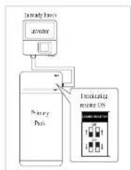
7.1.1 Setting for communication termination resistor (About Section B)
When you install the pack as primary, Turn ON the DIP switch for communication termination resistance.
When you install the pack is secondary. Turn OFF the DIP switch for communication termination resistor.
flowchart
graph TD
    A["Microcontroller"] --> B["Primary Bus"]
    B --> C["Optional motor ON"]
    C --> D["Port 1"]
    C --> E["Port 2"]
- Case 1: When installing one battery pack, Turn ON the DIP switch for communication termination resistor. (It is ON when switches are lowered.)
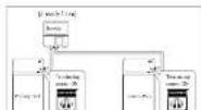
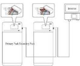
Case 2-1. When installing two battery packs, and inverter has two communication ports separately for each battery pack, Turn ON the all DIP switches for communication termination resistor of both packs.
flowchart
graph TD
    A["Primary Mask Sourcing Pack"] --> B["Sensor Input"]
    C["Inverter"] --> D["Device"]
    B --> E["Sensor Output"]
    D --> E
In the case of products using a combiner box, communication lines can also be connected through the combiner box.
The communication termination resistor can be changed depending on the inverter model, not the battery's own condition. Therefore, you must refer to the battery communication connection description in the inverter installation guide. Below are some examples according to the inverter model.
[When only 1 pack is installed]
| Invener model | SMA SolarEdge | Other models(Case 1) | |
| SUNNY BUYSTORAGE2.5/3.7/5.0/6.0(Case 1) | Energy Hub (Case 1) | ||
| Primary / Secondary Primary Primary Primary | |||
| Communication resistance | ON ON ON | ||
[When installing 2 packs]
| Invener model | SMA SolarEdge | Other models | ||
| SUNNY BOY STORAGE2.5/3.7/5.0/6.0(Case 2-1) | Energy Hub (Case 2-2) | |||
| Primary / Secondary Communication resistance | Primary Primary Primary Standard | Refer to the | overer installation manual. | |
| ON UN ON OFF | ||||
7.1.2 Power cable (When using a combiner box)
Power cable is connected by combiner box. Positive and negative line should be connected same polarity line by combiner box. Joint connection is in the combiner box. If installer connected reverse polarity position of the power line, the battery system is not normally
7.2 RMD Applications
7.2.1 Battery Status check via RMD
How to check the battery status is as follows.
1) RMD Wi-Fi direct connection
First, proceed with RMD Wi-Fi direct connection as shown below.
Search and access the SSID of the RMD AP from a device (hereinafter referred to as a device) supporting WLAN Station functions such as a smartphone:
RMD SSID has a structure of "RESU_ (or RMD) + RMD WLAN STM MAC ADDRESS". For the devices below, the SSID of the RMD SoftAP is "RESU_44CBXXXC14F (or RMD44CBXXXC14F)". The password is 12345678(echangeable)
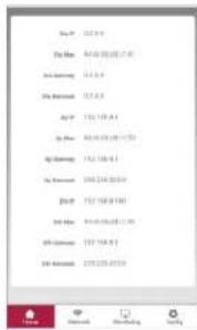
2) RMD Web page access
- Start a web browser on the device and enter 192.168.4.1 in the address bar. If the following screen is displayed after input, you have successfully connected to the RMD web server.

Fault Name error code Support action required
| Over Voltage Fault2 DiagResultFault2 (0x000) | Return the battery to 1 G Energy Solution. | |
| Under Voltage Fault2 DiagResultFault2 (0x000) Battery pack On and check additional errors. In case of normal operation, Charge the Battery pack in over 80% with inverter. Retrieve pack if issue occurs repeatedly. | ||
| Over Temperature Fault2 DiagResultFault2 (0x0400) | 1. If there is a heat source nearby or the wind of the air conditioner is directly hitting it, remove the heat source.2. Lower the temperature down to room temperature. Ket until battery temperature matches room temperature, then turn on the CFL. Retrieve pack if issue occurs repeatedly. | |
| Under Temperature Fault2 DiagResultFault2 (0x000) | 1. If ice buck up on the battery surface. Remove ice.2. Increase the temperature up to room temperature. Ket until battery temperature matches ambient temperature, then turn on the CFL. Retrieve pack if issue occurs repeatedly. | |
| Over Charge Current Fault2 DiagResultFault2 (0x0020) | ||
| Over Discharge Current Fault2 | DiagResultFault2 (0x0040) | Check if the stepwiring is connect properly and inverter confirm gurations are valid, then turn on the CFL. Retrieve pack if issue occurs repeatedly. |
| Over Charge Power Limit Fault2 | DiagResultFault2 (0x000) | |
| Over Discharge Power Limit Fault2 | DiagResultFault2 (0x000) | |
| External Communication Fault2 (HMS-DC1DC LOC) | DiagResultFault2 (0x4000) | Check the communication line.If there is no abnormality in the communication line, battery pack on and check additional errors. Retrieve pack if issue occurs repeatedly. |
| Internal Communication Fault2 (MCC-DMC Comm. In BMS) | DiagResultFault2 (0x2000) | Reconnect the cable between Top cover away and HMA. Retrieve pack if issue occurs repeatedly. |
DiasRequirtheFault? By/014
7.2.2 BMS, DC/DC and RMD Update via RMD
Have to download the firmware before starting the update, visit the LG ESS Battery Website
and check the Home Bailey Partner > Technical Support, Items.
1) RMD Wi-Fi dirter connection
First, proceed with RMD Wi-Fi direct connection as shown below.
Search and access the SSID of the RMD AP from a device (hereinafter referred to as a device)
Supporting WLSN Silicon metallic tech is a smartphone.
For the devices below, the SSD of the RMD SoftAR is *RKST_4HCXXXXC14F0.
RMD4HCBXXXC14F)" The password is 12345678(changable)
2) RMD Web page access
- Start a web browser on the device and enter 192.168.4.1 in the address bus. If the
following screen is displayed after input, you have successfully connected to the
31 BMS, DC/DC and RMD Update
Con upgrade F/W. Upgrade is performed on the following three targets.
-RMD
张长
- DC/DC
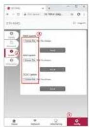
Click the 'Confi g' button
-
Click the 'Update' button
-
According to the target you want to update, click the 'Choose File' button.
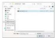
- Select a update file
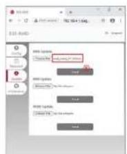
- After checking if the file is selected correctly, click the 'Send' button.
7.2.3 Installation via RMD for web user
7.2.3.1 User Agreement
Visit https://resumcnoe.lgersel.com and Sign in.
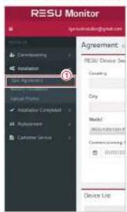
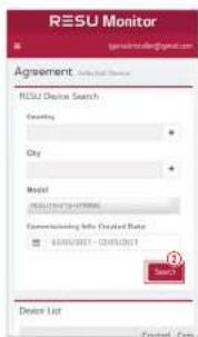
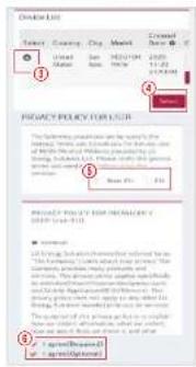
Click installation → User Agreement and search the product which you will install. Select your reason (Num EDUCL).

7.2.3.2 Battery Installation (RMD Setup)

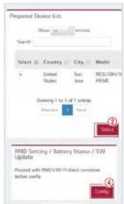
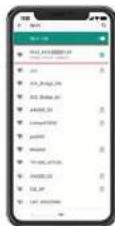
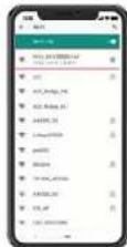
Click Installation - Battery Installation and select the device the prepared device list.
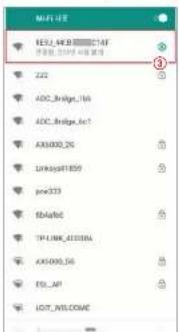
Search and access the SSID of the RMD AP from a device (hereinafter referred to as a device) supporting WLAN Station functions such as a smartphone.
RMD SSID has a structure of "RESU [or RMD] + RMD WLAN STM MAC ADDRESS". For the devices below, the SSID of the RMD SoftAP is "RESU 44CBXXXC14F(or
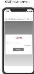
7.2.3.3 RMD Web Log-in
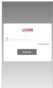
Enter the password and click "Register" to go to the home screen. The default password is set to 123-456 and can be changed in the Web UI.
7.2.3.4 Config setting
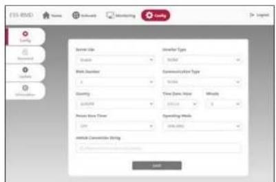
- Server Use: Decide whether to use (connect) to the cloud server.
- Inverter Type: N/A
- BMA Number : Select number of Modules: Select 2
- Contents
- Safety
- Product Introduction
- Installation
- Commissioning
- Troubleshooting
- Uninstallation & Return
- Appendix
- Symbols
- Safety Instructions
- General Safety Precautions
- Battery Handling Guide
- Response to Emergency Situations
- • Utilize fire-extinguishing media
- • Follow proper fire-fighting instructions
- WARNING
- • Effective ways to deal with accidents
- Warning Label
- Traccability label
- Technical Data
- Short Circuit Current/Duration
- Arc Flash Protection Calculations
- Features
- Maintenance
- Mechanical Requirements
- Package Contents
- Basic lifting guide
- Unboxing the Package
- CAUTION
- Installation Location
- Requirements:
- Recommendations:
- Clearance
- Tools & Safety Gear Required
- - Tools
- • Safety Gear for Personal Protection
- Appearance and Dimensions
- - Appearance
- • Pack appearance and dimensions
- • Color and materials
- System Clearance
- NOTE
- Installing the Battery Pack
- Installation process for Remote Monitoring Device (RMD)
- Prepare for installation using RMD
- Installer Sign In
- User Registration
- Installation via RMD
- Powering On the Product
- RMD App Log-in
- User Agreement
- RMD Wi-Fi Direct Connection
- QR Code Scan
- External Internet Connection
- RMD Configuration Setup
- Server Connection and Battery Status Check
- RMD Wi-Fi Disconnection
- Cable Connections
- Cable Configuration
- Guide for cable connection and setting the DIP switch
- Spring Terminal Blocks
- LED Indicators
- Troubleshooting Overview
- Post-Installation Checklist
- Troubleshooting Guidelines
- If the battery LED power indicator is OFF
- If the LED power indicator is ON, but the battery is not charging or discharging
- If the LED fault indicator is ON
- Return/Replacement Instructions
- Uninstallation
- ENGLISH
- Contact Information
- Connection in RESU16H Prime parallel battery system
- Setting for communication termination resistor (About Section B)
- Power cable (When using a combiner box)
- RMD Applications
- Battery Status check via RMD
- 1) RMD Wi-Fi direct connection
- 2) RMD Web page access
- BMS, DC/DC and RMD Update via RMD
- 1) RMD Wi-Fi dirter connection
- BMS, DC/DC and RMD Update
- Installation via RMD for web user
- User Agreement
- Battery Installation (RMD Setup)
- RMD Web Log-in
- Config setting
Brand : LG
Model : RESU16H Prime
Category : Battery