
PVR07R - Air conditioner Philco - Free user manual and instructions
Find the device manual for free PVR07R Philco in PDF.


| Product Type | Window Type Room Air Conditioner |
| Model | PVR07R |
| Refrigerant | R32 (mildly flammable) |
| Cooling Capacity | 7000 BTU/h (approx.) |
| Heating Capacity | Not specified (may vary by model) |
| Power Supply | 220-240 V, 50 Hz, single phase |
| Dimensions (W x H x D) | 451 x 346 x 535 mm (approx.) |
| Operating Modes | Auto, Cool, Heat (if applicable), Fan, Dry |
| Fan Speeds | Low, Med, High |
| Temperature Range (Cooling) | Indoor: 17-32°C, Outdoor: 18-43°C |
| Temperature Range (Heating) | Indoor: 0-27°C, Outdoor: -5-24°C (if applicable) |
| Timer | Auto start/stop up to 24 hours |
| Sleep Mode | Yes (gradual temperature adjustment) |
| Swing Function | Yes (automatic air swing) |
| Additional Functions | Turbo, UV, ECO (on some models) |
| Air Filter Cleaning | Every 2 weeks (recommended) |
| Water Drainage | Bottom, back, or non-drainage options |
| Installation | Must be performed by qualified personnel |
| Safety Features | R32 refrigerant detection, overcurrent protection, auto restart after power failure |
| Accessories Included | Remote controller, drain joint, drain pan, rubber plug, screws, seal, etc. |
Frequently Asked Questions - PVR07R Philco
User questions about PVR07R Philco
0 question about this device. Answer the ones you know or ask your own.
Ask a new question about this device
Download the instructions for your Air conditioner in PDF format for free! Find your manual PVR07R - Philco and take your electronic device back in hand. On this page are published all the documents necessary for the use of your device. PVR07R by Philco.
USER MANUAL PVR07R Philco
EN Window Type Room Air Conditioner
User Manual 2
CN 窗式空調器
用戶使用手冊 19

natural_image
Black-and-white photo of large icebergs floating on calm water under cloudy sky (no text or symbols visible)PHILCO®

MODEL:
PVR07R PVR09R PVR12R
PVR18R PVR21R
IMPORTANT NOTE:
重要提示:

This appliance is using R32 mildly flammable refrigerant.
此設備使用輕度易燃製冷劑R32。

Read this manual carefully before installing or operating your new air conditioning unit.
Make sure to save this manual for future reference.
Please check the applicable models, technical data from the nameplate pasted on the unit.
Read Safety Precautions Before Operation and Installation
Incorrect installation due to ignore of instructions can cause serious damage or injury.

WARNING
- Installation must be performed by an authorized dealer or professionally trained technician.
-
Installation
-
Where refrigerant pipes shall be compliance with national gas regulations.
- That mechanical connections shall be accessible for maintenance purposes.
- In cases that require mechanical ventilation, ventilation openings shall be kept clear of obstruction.
-
When disposing of the product is used, be based on national regulations, properly processed.
-
Servicing
- Any person who is involved with working on or breaking into a refrigerant circuit should hold a current valid certificate from an industry-accredited assessment authority, which authorises their competence to handle refrigerants safely in accordance with an industry recognised assessment specification.
- Maintenance and repair requires the assistance of other skilled personnel shall be carried out under the supervision of the person competent in the use of flammable refrigerants.
- Do not use means to accelerate the defrosting process or to clean, other than those recommended by the manufacturer.
- The appliance shall be stored in a room without continuously operating ignition sources (for example: open flames, an operating gas appliance or an operating electric heater)
- Be more careful that foreign matter(oil, water, etc) does not enter the piping. Also, when storing the piping, securely seal the opening by pinching, taping, etc.
- Do not pierce or burn.
- Be aware that refrigerants may not contain an odour.
- All working procedure that affects safety means shall only be carried by competent persons.
- Appliance shall be stored in a well-ventilated area where the room size corresponds to the room area as specified for operation.
- The appliance shall be stored so as to prevent mechanical damage from occurring.
- The appliance is using mildly flammable refrigerant R32 and tested to comply with IEC 60335-2-40. There is no minimum room area requirement for the appliance.
- The installation height shall not be lower than 0.75m.
Transportation, marking and storage for units
- Transport of equipment containing flammable refrigerants Compliance with the transport regulations
- Marking of equipment using signs Compliance with local regulations
- Disposal of equipment using flammable refrigerants Compliance with national regulations
- Storage of equipment/appliances The storage of equipment should be in accordance with the manufacturer's instructions.
- Storage of packed (unsold) equipment Storage package protection should be constructed such that mechanical damage to the equipment inside the package will not cause a leak of the refrigerant charge. The maximum number of pieces of equipment permitted to be stored together will be determined by local regulations.
Explanation of symbols displayed on the unit
 | WARNING | This symbol shows that this appliance used a mildly flammable refrigerant. If the refrigerant is leaked and exposed to an external ignition source, there is a risk of fire. |
 | CAUTION | This symbol shows that the user manual should be read carefully. |
 | CAUTION | This symbol shows that a service personnel should be handling this equipment with reference to the installation manual. |
 | CAUTION | This symbol shows that information is available such as the user manual or installation manual. |
Table of Contents
Warning 05
Unit Parts Identification 11
Operation Instructions....12
Care and Maintenance....14
Water Drainage 14
Installation Instructions ....15
Troubleshooting....17
Specifications ....18
Disposal Requirement in Hong Kong
Use authorized disposal sites for your old appliance. Help to keep your country tidy!
This appliance is using R32 mildly flammable refrigerant.
The symbol 📋 on the product or on its packaging indicates that this product may not be treated as household waste.
Instead it shall be handed over to the applicable collection point for the recycling of electrical and electronic equipment. By ensuring this product is disposed of correctly, you will help prevent potential negative consequences for the environment and human health, which could otherwise be caused by inappropriate waste handling of this product.
For more detailed information about recycling of this product, please contact your local city office, your household waste disposal service or the shop where you purchased the product.
Warning
Read Before Operation and Installation
Incorrect installation due to ignoring instructions can cause serious damage or injury.
The seriousness of potential damage or injuries is classified as either a WARNING or CAUTION.

WARNING
This symbol indicates the possibility of personnel injury or loss of life.

CAUTION
This symbol indicates the possibility of property damage or serious consequences.

WARNING
This appliance can be used by children aged from 8 years and above and persons with reduced physical, sensory or mental capabilities or lack of experience and knowledge if they have been given supervision or instruction concerning use of the appliance in a safe way and understand the hazards involved. Children shall not play with the appliance. Cleaning and user maintenance shall not be made by children without supervision(EN Standard requirements).
This appliance is not intended for use by persons(including children) with reduced physical, sensory or mental capabilities, or lack of experience and knowledge, unless they have been given supervision or instruction concerning use of the appliance by a person responsible for their safety. Children should be supervised to ensure that they do not play with the appliance.

WARNINGS FOR PRODUCT USE
• This appliance is using R32 mildly flammable refrigerant.
- If an abnormal situation arises (like a burning smell), immediately turn off the unit and disconnect the power. Call your dealer for instructions to avoid electric shock, fire or injury.
- Do not insert fingers, rods or other objects into the air inlet or outlet. This may cause injury, since the fan may be rotating at high speeds.
- Do not use flammable sprays such as hair spray, lacquer or paint near the unit. This may cause fire or combustion.
- Do not operate the air conditioner in places near or around combustible gases. Emitted gas may collect around the unit and cause explosion.
- Do not operate your air conditioner in a wet room such as a bathroom or laundry room. Too much exposure to water can cause electrical components to short circuit.
- Do not expose your body directly to cool air for a prolonged period of time.
- Do not allow children to play with the air conditioner. Children must be supervised around the unit at all times.
- If the air conditioner is used together with burners or other heating devices, thoroughly ventilate the room to avoid oxygen deficiency.
- In certain functional environments, such as kitchens, server rooms, etc., the use of specially designed air-conditioning units is highly recommended.
- Unplug the unit or disconnect the power supply to the unit if strange sounds, smell, or smokecomes from it.
- To further optimize the performance of your unit, keep doors and windows closed during operation.
- Pay attention when unpacking and installing. Sharp edges could cause injury.
CLEANING AND MAINTENANCE WARNINGS
- Turn off the device and disconnect the power before cleaning. Failure to do so can cause electrical shock.
- Do not clean the air conditioner with excessive amounts of water.
- Do not clean the air conditioner with combustible cleaning agents. Combustible cleaning agents can cause fire or deformation.

CAUTION
- Turn off the air conditioner and disconnect the power if you are not going to use it for a long time.
• Turn off and unplug the unit during storms.
• Make sure that water condensation can drain unhindered from the unit. - Do not operate the air conditioner with wet hands. This may cause electric shock.
- Do not use device for any other purpose than its intended use.
- Do not climb onto or place objects on top of the outdoor unit.
- Do not allow the air conditioner to operate for long periods of time with doors or windows open, or if the humidity is very high.

ELECTRICAL WARNINGS
- Only use the specified power cord. If the power cord is damaged, it must be replaced by the manufacturer, its service agent or similarly qualified persons in order to avoid a hazard.
- Keep power plug clean. Remove any dust or grime that accumulates on or around the plug. Dirty plugs can cause fire or electric shock.
- Do not pull power cord to unplug unit. Hold the plug firmly and pull it from the outlet. Pulling directly on the cord can damage it, which can lead to fire or electric shock.
Do not modify the length of the power supply cord or use an extension cord to power the unit. - Do not share the electrical outlet with other appliances. Improper or insufficient power supply can cause fire or electrical shock. Always install circuit breaker and a dedicated power circuit.
- Do not use the socket if it is loose or damaged.
- Do not place heavy object on the power cord and ensure that the cord is not compressed.
There is danger of fire or electric shock. - If water enters the unit, turn the unit off at the power outlet and switch off the circuit breaker. Isolate supply by taking the power-plug out or disconnect the power supply to the unit, contacta qualified service technician.
- The product must be properly grounded at the time of installation, or electrical shock may occur.
- For all electrical work, follow all local and national wiring standards, regulations, and the Electrical Connection Diagram located on the top panel of the unit.
- If connecting power to fixed wiring, an all-pole disconnection device which has at least 3mm clearances in all poles, and have a leakage current that may exceed 10mA, the residual current device(RCD) having a rated residual operating current not exceeding 30mA, and disconnection must be incorporated in the fixed wiring in accordance with the wiring rules.
- This unit is earthed through the power cord, make sure that the unit is correctly grounded. The wall outlet(Air-break switch) should be provided with reliable earth wire.
- The unit should be provided with an individual circuit and the circuit breaker/fuse rating should be the same as that of the power cord and wall outlet. Power cord conductors are distinguished according to the color as shown in Wiring Diagram located on the top of the machine.
Wall outlet

Air-break switch

TAKE NOTE OF FUSE SPECIFICATIONS
The air conditioner's circuit board (PCB) is designed with a fuse to provide overcurrent protection. The specifications of the fuse are printed on the circuit board, such as 220V.

WARNINGS FOR PRODUCT INSTALLATION
- Installation must be performed by an authorized dealer or specialist. Defective installation can cause water leakage, electrical shock, or fire.
- Installation must be performed according to the installation instructions. Improper installation can cause water leakage, electrical shock, or fire. (In North America, installation must be performed in accordance with the requirement of NEC and CEC by authorized personnel only.)
- Contact an authorized service technician for repair or maintenance of this unit. This appliance shall be installed in accordance with national wiring regulations.
- Only use the included accessories, parts, and specified parts for installation. Using non-standard parts can cause water leakage, electrical shock, fire, and can cause the unit to fail.
- Install the unit in a firm location that can support the unit's weight. If the chosen location cannot support the unit's weight, or the installation is not done properly, the unit may drop and cause serious injury and damage.
- Install drainage piping according to the instructions in this manual. Improper drainage may cause water damage to your home and property.
- For units that have an auxiliary electric heater, do not install the unit within 1 meter (3 feet) of any combustible materials.
- Do not install the unit in a location that may be exposed to combustible gas leaks. If combustible gas accumulates around the unit, it may cause fire.
- Do not turn on the power until all work has been completed.
- When moving or relocating the air conditioner, consult experienced service technicians for disconnection and reinstallation of the unit.
- How to install the appliance to its support, please read the information for details in "Installation instructions" section.

WARNING for Using R32 Refrigerant
-Do not use means to accelerate the defrosting process or to clean, other than those recommended by the manufacturer.
-The appliance shall be stored in a room without continuously operating ignition sources (for example: open flames, an operating gas appliance) and ignition sourcesor (for example:an operating electric heater) close to the appliance. The appliance shall be stored in a room without continuously operating ignition sources (for example: open flames, an operating gas appliance or an operating electric heater).
-Do not pierce or burn.
-Be aware that the refrigerants may not contain an odour.
-Compliance with national gas regulations shall be observed.
-Keep ventilation openings clear of obstruction.
-The appliance shall be stored so as to prevent mechanical damage from occurring.
-A warning that the appliance shall be stored in a well-ventilated area where the room size corresponds to the room area as specified for operation.
-Any person who is involved with working on or breaking into a refrigerant circuit should hold a current valid certificate from an industry-accredited assessment authority, which authorises their competence to handle refrigerants safely in accordance with an industry recognised assessment specification.
-Servicing shall only be performed as recommended by the equipment manufacturer. Maintenance and repair requiring the assistance of other skilled personnel shall be carried out under the supervision of the person competent in the use of flammable refrigerants.
-Please follow the instruction carefully to handle, install, clear, service the air conditioner to avoid any damage or hazard. Mildly flammable Refrigerant R32 is used within air conditioner. When maintaining or disposing the air conditioner, the refrigerant (R32) shall be recovered properly, shall not discharge to air directly.
-No any open fire or device like switch which may generate spark/arcing shall be around air conditioner to avoid causing ignition of the flammable refrigerant used. Please follow the instruction carefully to store or maintain the air conditioner to prevent mechanical damage from occurring.
- Mildly flammable refrigerant is used in air conditioner. Please follow the instruction carefully to avoid any hazard.
natural_image
Warning symbol depicting flame inside a triangle (no text or numbers)Warning: low burning velocity material
(For R32 models apply to
IEC60335-2-40:2018)

natural_image
Simple line drawing of an open book with no text or symbols visibleIMPORTANT NOTE: Read this manual carefully before installing or operating your new air conditioning unit.
Explanation of symbols displayed on the unit(For the unit adopts R32 Refrigerant only):
 | WARNING | This symbol shows that this appliance used a mildly flammable refrigerant. If the refrigerant is leaked and exposed to an external ignition source, there is a risk of fire. |  | CAUTION | This symbol shows that a service personnel should be handling this equipment with reference to the installation manual. |
 | CAUTION | This symbol shows that the user manual should be read carefully. |  | CAUTION | This symbol shows that information is available such as the user manual or installation manual. |
1. Transport of equipment containing flammable refrigerants
See transport regulations
2. Marking of equipment using signs
See local regulations
3.Disposal of equipment using flammable refrigerants
See national regulations.
4.Storage of equipment/appliances
The storage of equipment should be in accordance with the manufacturer's instructions.
5.Storage of packed (unsold) equipment
Storage package protection should be constructed such that mechanical damage to the equipment inside the package will not cause a leak of the refrigerant charge. The maximum number of pieces of equipment permitted to be stored together will be determined by local regulations.
6.Information on servicing
1) Checks to the area
Prior to beginning work on systems containing flammable refrigerants, safety checks are necessary to ensure that the risk of ignition is minimised. For repair to the refrigerating system, the following precautions shall be complied with prior to conducting work on the system.
2)Work procedure
Work shall be undertaken under a controlled procedure so as to minimise the risk of a flammable gas or vapour being present while the work is being performed.
3) General work area
All maintenance staff and others working in the local area shall be instructed on the nature of work being carried out. Work in confined spaces shall be avoided. The area around the workspace shall be sectioned off. Ensure that the conditions within the area have been made safe by control of flammable material.
4) Checking for presence of refrigerant
The area shall be checked with an appropriate refrigerant detector prior to and during work, to ensure the technician is aware of potentially flammable atmospheres. Ensure that the leak detection equipment being used is suitable for use with flammable refrigerants, i.e. non-sparking, adequately sealed or intrinsically safe.
5) Presence of fire extinguisher
If any hot work is to be conducted on the refrigeration equipment or any associated parts, appropriate fire extinguishing equipment shall be available to hand. Have a dry powder or CO2 fire extinguisher adjacent to the charging area.
6) No ignition sources
No person carrying out work in relation to a refrigeration system which involves exposing any pipe work that contains or has contained flammable refrigerant shall use any sources of ignition in such a manner that it may lead to the risk of fire or explosion. All possible ignition sources, including cigarette smoking, should be kept sufficiently far away from the site of installation, repairing, removing and disposal, during which flammable refrigerant can possibly be released to the surrounding space. Prior to work taking place, the area around the equipment is to be surveyed to make sure that there are no flammable hazards or ignition risks. No Smoking signs shall be displayed.
7) Ventilated area
Ensure that the area is in the open or that it is adequately ventilated before breaking into the system or conducting any hot work. A degree of ventilation shall continue during the period that the work is carried out. The ventilation should safely disperse any released refrigerant and preferably expel it externally into the atmosphere.
8) Checks to the refrigeration equipment
Where electrical components are being changed, they shall be fit for the purpose and to the correct specification. At all times the manufacturer's maintenance and service guidelines shall be followed. If in doubt consult the manufacturer's technical department for assistance. The following checks shall be applied to installations using flammable refrigerants: The charge size is in accordance with the room size within which the refrigerant containing parts are installed; The ventilation machinery and outlets are operating adequately and are not obstructed; If an indirect refrigerating circuit is being used, the secondary circuit shall be checked for the presence of refrigerant; Marking to the equipment continues to be visible and legible. Markings and signs that are illegible shall be corrected; Refrigeration pipe or components are installed in a position where they are unlikely to be exposed to any substance which may corrode refrigerant containing components, unless the components are constructed of materials which are inherently resistant to being corroded or are suitably protected against being so corroded.
9) Checks to electrical devices
Repair and maintenance to electrical components shall include initial safety checks and component inspection procedures. If a fault exists that could compromise safety, then no electrical supply shall be connected to the circuit until it is satisfactorily dealt with. If the fault cannot be corrected immediately but it is necessary to continue operation, an adequate temporary solution shall be used. This shall be reported to the owner of the equipment so all parties are advised. Initial safety checks shall include:
That capacitors are discharged: this shall be done in a safe manner to avoid possibility of sparking;
That there no live electrical components and wiring are exposed while charging, recovering or purging the system; That there is continuity of earth bonding.
7. Repairs to sealed components
1) During repairs to sealed components, all electrical supplies shall be disconnected from the equipment being worked upon prior to any removal of sealed covers, etc. If it is absolutely necessary to have an electrical supply to equipment during servicing, then a permanently operating form of leak detection shall be located at the most critical point to warn of a potentially hazardous situation.
2) Particular attention shall be paid to the following to ensure that by working on electrical components, the casing is not altered in such a way that the level of protection is affected. This shall include damage to cables, excessive number of connections, terminals not made to original specification, damage to seals, incorrect fitting of glands, etc. Ensure that apparatus is mounted securely.
Ensure that seals or sealing materials have not degraded such that they no longer serve the purpose of preventing the ingress of flammable atmospheres. Replacement parts shall be in accordance with the manufacturer's specifications.
NOTE: The use of silicon sealant may inhibit the effectiveness of some types of leak detection equipment. Intrinsically safe components do not have to be isolated prior to working on them.
8. Repair to intrinsically safe components
Do not apply any permanent inductive or capacitance loads to the circuit without ensuring that this will not exceed the permissible voltage and current permitted for the equipment in use. Intrinsically safe components are the only types that can be worked on while live in the presence of a flammable atmosphere. The test apparatus shall be at the correct rating. Replace components only with parts specified by the manufacturer. Other parts may result in the ignition of refrigerant in the atmosphere from a leak.
9.Cabling
Check that cabling will not be subject to wear, corrosion, excessive pressure, vibration, sharp edges or any other adverse environmental effects. The check shall also take into account the effects of aging or continual vibration from sources such as compressors or fans.
10. Detection of flammable refrigerants
Under no circumstances shall potential sources of ignition be used in the searching for or detection of refrigerant leaks. A halide torch (or any other detector using a naked flame) shall not be used.
11.Leak detection methods
The following leak detection methods are deemed acceptable for systems containing flammable refrigerants. Electronic leak detectors shall be used to detect flammable refrigerants, but the sensitivity may not be adequate, or may need recalibration. (Detection equipment shall be calibrated in a refrigerant-free area.) Ensure that the detector is not a potential source of ignition and is suitable for the refrigerant used. Leak detection equipment shall be set at a percentage of the LFL of the refrigerant and shall be calibrated to the refrigerant employed and the appropriate percentage of gas (25 % maximum) is confirmed. Leak detection fluids are suitable for use with most refrigerants but the use of detergents containing chlorine shall be avoided as the chlorine may react with the refrigerant and corrode the copper pipe-work. If a leak is suspected, all naked flames shall be removed/ extinguished. If a leakage of refrigerant is found which requires brazing, all of the refrigerant shall be recovered from the system, or isolated (by means of shut off valves) in a part of the system remote from the leak. Oxygen free nitrogen (OFN) shall then be purged through the system both before and during the brazing process.
12. Removal and evacuation
When breaking into the refrigerant circuit to make repairs or for any other purpose conventional procedures shall be used. However, it is important that best practice is followed since flammability is a consideration. Opening of the refrigeration systems shall not be done by brazing. The following procedure shall be adhered to:
Remove refrigerant;
Purge the circuit with inert gas;
Evacuate;
Purge again with inert gas;
Open the circuit by cutting or brazing.
The refrigerant charge shall be recovered into the correct recovery cylinders. The system shall be flushed with OFN to render the unit safe. This process may need to be repeated several times. Compressed air or oxygen shall not be used for this task.
Flushing shall be achieved by breaking the vacuum in the system with OFN and continuing to fill until the working pressure is achieved, then venting to atmosphere, and finally pulling down to a vacuum. This process shall be repeated until no refrigerant is within the system.
When the final OFN charge is used, the system shall be vented down to atmospheric pressure to enable work to take place. This operation is absolutely vital if brazing operations on the pipe-work are to take place.
Ensure that the outlet for the vacuum pump is not close to any ignition sources and there is ventilation available.
13. Charging procedures
In addition to conventional charging procedures, the following requirements shall be followed. Ensure that contamination of different refrigerants does not occur when using charging equipment. Hoses or lines shall be as short as possible to minimise the amount of refrigerant contained in them.
Cylinders shall be kept upright.
Ensure that the refrigeration system is earthed prior to charging the system with refrigerant.
Label the system when charging is complete (if not already).
Extreme care shall be taken not to overfill the refrigeration system.
Prior to recharging the system it shall be pressure tested with OFN. The system shall be leak tested on completion of charging but prior to commissioning. A follow up leak test shall be carried out prior to leaving the site.
14.Decommissioning
Before carrying out this procedure, it is essential that the technician is completely familiar with the equipment and all its detail. It is recommended good practice that all refrigerants are recovered safely. Prior to the task being carried out, an oil and refrigerant sample shall be taken in case analysis is required prior to re-use of reclaimed refrigerant. It is essential that electrical power is available before the task is commenced.
a)Become familiar with the equipment and its operation.
b) Isolate system electrically.
c) Before attempting the procedure ensure that:
Mechanical handling equipment is available, if required, for handling refrigerant cylinders;
All personal protective equipment is available and being used correctly;
The recovery process is supervised at all times by a competent person;
Recovery equipment and cylinders conform to the appropriate standards.
d) Pump down refrigerant system, if possible.
e)If a vacuum is not possible, make a manifold so that refrigerant can be removed from various parts of the system.
f) Make sure that cylinder is situated on the scales before recovery takes place.
g) Start the recovery machine and operate in accordance with manufacturer's instructions.
h)Do not overfill cylinders. (No more than 80 % volume liquid charge).
i) Do not exceed the maximum working pressure of the cylinder, even temporarily.
j)When the cylinders have been filled correctly and the process completed, make sure that the cylinders and the equipment are removed from site promptly and all isolation valves on the equipment are closed off.
k)Recovered refrigerant shall not be charged into another refrigeration system unless it has been cleaned and checked.
15.Labelling
Equipment shall be labelled stating that it has been de-commissioned and emptied of refrigerant. The label shall be dated and signed. Ensure that there are labels on the equipment stating the equipment contains flammable refrigerant.
16.Recovery
When removing refrigerant from a system, either for servicing or decommissioning, it is recommended good practice that all refrigerants are removed safely. When transferring refrigerant into cylinders, ensure that only appropriate refrigerant recovery cylinders are employed. Ensure that the correct number of cylinders for holding the total system charge is available.
All cylinders to be used are designated for the recovered refrigerant and labelled for that refrigerant (i.e. special cylinders for the recovery of refrigerant). Cylinders shall be complete with pressure relief valve and associated shut-off valves in good working order. Empty recovery cylinders are evacuated and, if possible, cooled before recovery occurs.
The recovery equipment shall be in good working order with a set of instructions concerning the equipment that is at hand and shall be suitable for the recovery of flammable refrigerants. In addition, a set of calibrated weighing scales shall be available and in good working order. Hoses shall be complete with leak-free disconnect couplings and in good condition.
Before using the recovery machine, check that it is in satisfactory working order, has been properly maintained and that any associated electrical components are sealed to prevent ignition in the event of a refrigerant release. Consult manufacturer if in doubt.
The recovered refrigerant shall be returned to the refrigerant supplier in the correct recovery cylinder, and the relevant Waste Transfer Note arranged. Do not mix refrigerants in recovery units and especially not in cylinders. If compressors or compressor oils are to be removed, ensure that they have been evacuated to an acceptable level to make certain that flammable refrigerant does not remain within the lubricant. The evacuation process shall be carried out prior to returning the compressor to the suppliers. Only electric heating to the compressor body shall be employed to accelerate this process. When oil is drained from a system, it shall be carried out safely.
When flammable refrigerant are employed, appliance shall be stored in a well -ventilated area.
Operating temperature
When your air conditioner is used outside of the following temperature ranges, certain safety protection features may activate and cause the unit to disable.
| Cooling operation | Outdoor Temperature | 18°C-43°C (64°F-109°F) |
| 18°C-52°C (64°F-126°F) (For special tropical models) | ||
| Indoor Temperature | 17°C-32°C (62°F-90°F) | |
| Heating operation | Outdoor Temperature | -5°C-24°C (23°F-76°F) |
| Indoor Temperature | 0°C-27°C (32°F-80°F) |
To further optimize the performance of your unit, do the following:
- Keep doors and windows closed.
- The capacity of the room air conditioner must fit the room size for efficient and satisfactory operation.
- Do not block air inlets or outlets.
• Regularly inspect and clean air filters.
- If the power supplied to the unit is not plus/minus 10% of the specified rating, the unit may not function and the fuse may blow.
- Noise from the air conditioner will be louder at night than in the daytime. This is because the noise in the surroundings is comparatively low at night. If your feel that the noise is too loud, switch the thermostat to lower numbers.
UNIT PARTS IDENTIFICATION
NOTE: Different models have different front panels and cabinets. Illustrations in this manual are for explanatory purposes. The actual shape of your indoor unit may be slightly different. The actual shape shall prevail. See the following figures for references:


- Front panel
- Air filter
- Frame
- Cabinet
- Air inlet grille (outdoor side)
- Air outlet grille
- Electronic control keypad
- Power supply cord
- Control panel cover (some units)
- Remote controller
Accessories
Seal(※) Drain Joint(※)
(Used on drain joint)

Drain Joint(※)

Drain pan(※)

Rubber Plug Screw


Wooden screw (optional) (※)

PVC sheath and cable ties(※)
1 pc 1 pc 1 pc
[※] Model dependent
1\~2 pc (depending on models)
2 pcs(For some units, used to fasten the front panel) 2 pcs or 4 pcs(used to install the drain pan)
8 pcs (depend on model you purchased)
1 pc 4 pcs
Vent Control
The vent control is located above the control knobs. The operation method and the shape may vary in different models (see the following figures)
For maximum cooling efficiency, CLOSE the vent. It will allow internal air circulation. OPEN the vent to discharge stale air.

NOTE: The vent control is not available for all the units. Some units do not have vent control.
OPERATING INSTRUCTIONS
NOTE: Different models have different operation panels. Not all the functions describing below are available for the air conditioner you purchased. Please check the operation panel of the unit you purchased. The following graphics are for explanatory purposes.
NOTE: Some models without MED fan speed feature and (or) AUTO mode feature and (or) swing feature.
POWER:
Press the POWER keypad to turn the unit on/off.
MODE:
Press the "MODE" keypad to select the appropriate operating mode. The mode selection will alternate between AUTO, HEAT (cooling only models without), COOL, FAN and DRY. The indicator light beside the "MODE" option will illuminate, identifying the mode selected.
NOTE: Press the "MODE" keypad to select the FAN mode, you can press "FAN" keypad to select your desired fan speed but you can not adjust temperature.
▲ TEMPERATURE SETTINGS UP:
Press the ▲ keypad to increase the set (operating) temperature of the unit. Each time the keypad is pressed the temperature increases as follows: 1 C (Celsius Scale) Maximum Setting 30 C/31 C.
▼ TEMPERATURE SETTINGS DOWN:
Press the ▼ keypad to decrease the set (operating) temperature of the unit. Each time the keypad is pressed the temperature decreases as follows: 1°C (Celsius Scale) Minimum Setting 17°C/16°C.
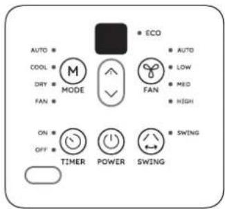


FAN:
Press this keypad to activate the appropriate fan speed setting. Each depression of the keypad will alternate through LOW, MED(on some models), HIGH fan speed options. The indicator light beside the FAN speed option will illuminate, identifying the fan speed selected.
SWING: (on some models)
Press the "SWING" keypad to activate the automatic air swing feature. The indicator light adjacent to the "SWING" keypad will illuminate, identifying to the selected mode is operational. The vertical louvers will oscillate back and forth (side to side) automatically sweeping air alternately for comfortable cooling/heating. To stop the air swing feature, press the "SWING" keypad again, the indicator light adjacent to the keypad will go off.
Wireless Operation: (on some models)
For the first time to use Wifi function, press the SWING button for 3 seconds to initiate the Wifi connection mode. The LED DISPLAY shows 'AP' to indicate you can set Wifi connection. If connection(router) is successful within 8 minutes, the unit will exit Wifi connection mode automatically and the Wireless indicator illuminates. If connection is failure within 8 minutes, the unit exits Wifi connection mode automatically.
TIMER: (on some models)
- When the unit is on, press the Timer button will initiate the Auto stop program, the TIMER OFF indicator light illuminates. Press the UP or down button to select the desired time. Press the TI MER button again within 10 seconds, the Auto start program is initiated. And the TI MER ON indicator light illuminates. Press the up or down button to select the desired Auto start time.
- When the unit is off, press the Timer button to initiate the Auto start program, press it again within 10 seconds will initiate the Auto stop program.
- Press or hold the UP or DOWN button to change the Auto time by 0.5 hour increments, up to 10 hours, then at 1 hour increments up to 24 hours. The control will count down the time remaining until start.
● The system will automatically revert back to display the previous temperature setting if there is no operation in a 10 seconds period - Turning the unit ON or OFF at any time or adjusting the timer setting to 0.0 will cancel the Auto Start/Stop timer program.
TIMER: (on some models)
Press the "TIMER" keypad to activate the "auto start/auto stop" timer function.
Auto start/stop programs can be set from 0\~12 hours. Each depression of the "TIMER" keypad will increase the selected time in 1 hour increments.
DRY: (on some models)
This mode is used to decrease the humidity in the room. Under this mode, you cannot select a fan speed. The fan motor operates at LOW speed. Keep windows and doors closed for the best dehumidifying effect.
COOL :
The temperature setting are adjustable between 17 C/16 C to 30 C/31 C. You can select your desired fan speed.
HEAT: (on some models)
The temperature settings are adjustable between 17 C/16 C to 30 C/31 C in heating mode. You can select your desired fan speed.
AUTO:
The fan motor remains on MED speed in AUTO mode. The unit will select the appropriate operating mode from FAN, COOL or HEAT(For reverse cycle models only) based upon the temperature difference between the actual and desired room temperature. Some models wihout MED speed, the fan motor operates on HIGH speed in AUTO mode.
SLEEP :
Press and hold the "SWING" keypad for 2 seconds or use the remote control to activate the "SLEEP" feature. Press and hold the "SWING" keypad for 2 seconds or use the remote control again to deactivate the "SLEEP" feature. In the Cooling mode, the cooling temperature set point will increase 1 C per hour after the "SLEEP" mode is selected. Two hours later, the set point will continue at this temperature and the fan motor will remain on LOW speed. In the Heating mode, the heating temperature set point will decrease 1 C per hour after the "SLEEP" mode is selected. Two hours later, the set point will continue at this temperature and the fan motor will remain on LOW speed. For Inverter Type the new temperature will be maintained for 7 hours, then the unit exits sleep mode and is off. Using the "SLEEP" mode will reduce noise creating a comfortable sleeping environment.
NOTE: This feature is not available under DRY and FAN ONLY operation.
Turbo function (on some models)
Press the TURBO button by remote controller on COOL/HEAT (For models adopts Electrical heater only) mode, the air conditioner goes into powerful cooling/heating operation. Press again to cancel the TURBO function.
UV function (on some models)
Press the FAN button for 3 seconds to initiate UV (UltraViolet C radiation) feature and the UV light illuminantes, the LED DISPLAY shows 'On' for 3 seconds for some units. The UV (UltraViolet C radiation) feature will help to purify the air inside. Press it for 3 seconds again to stop the UV feature and the UV light turn dark, the LED DISPLAY shows 'OF' for 3 seconds for some units.
ECO function(on some models)
Press the ECO button by remote controller on COOL mode to enter the energy efficient mode.
LED Display:
● Displays room temperature on fan only mode, displays the setting temperature on the other modes.
● Displays times during Timer setting, after 10 seconds, the system will revert back to display the setting temperature.
Shows Error codes:(Inverter Type)
E0: Indoor EEPROM error;
E1: Indoor & outdoor communicaiton error;
E3: Indoor fan motor speed out of control;
E4: Room temperature sensor error;
E5: Evaporator temperature sensor error;
EC: Refrigerant leakage detection;
F0: Current overload protection;
F1: Outdoor temperature sensor error;
F2: Condenser temperature sensor error;
Note: When one of the above malfunctions occurs, turn off the unit, and check for any obstructions. Restart the unit, if the malfunction is still present, turn off the unit and unplug the power cord. Contact the manufacturer or its service agents or a similar qualified person for service.
F3: Exhaust temperature sensor error;
F4: Outdoor electric EE error;
PO: IPM module error;
P1: Voltage too high/too low protection;
P2: Potection of IPM high temperature;
P3: Potection of outdoor temperature too low
(For the Cooling & Heating models);
P4: Potection of compressor location;
P7: Outdoor IGBT sensor error.
Shows Error codes:(Fixed-speed Type)
Er Indicates a malfunction of the indoor room temperature sensor
En Indicates a malfunction of the evaporator temperature sensor
Eo Indicates a malfunction of the outdoor condenser temperature sensor
Note: When one of the above malfunctions occurs, turn off the unit, and check for any obstructions.
Restart the unit, if the malfunction is still present, turn off the unit and unplug the power cord.
Contact the manufacturer or its service agents or a similar qualified person for service.
εd Indicates frosting protection (Turn off the unit and restart it to return to normal operation).
_1 Indicates the requirement of a filter check after 720 hours of fan operation. Turn off the unit, disconnect/unplug from the power supply. Clean the filter, then restore the power, the unit will return to normal operation. This is a reminder to clean the Air Filter for more efficient operation. In the event of a power failure, the "EI" program is automatically re-set. Therefore we suggest you remove and clean the filter before restarting the unit after any power failure. (On some models)
Operation panel cover (some units)
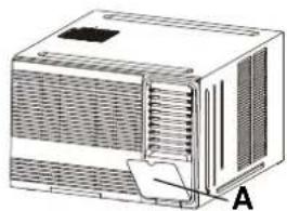
For the units with operation panel cover (see the left figures of A & B)
- Grasp the top or the left of the operation cover and pull it to open it.
- Close the operation cover and press the cover again until it snaps into the locked position.
DO NOT press or swing the opened operation cover.
natural_image
Illustration of a rectangular electronic device with ventilation grilles and a paper clip labeled A (no text or symbols on the device itself)
natural_image
Technical illustration of a modular air conditioner unit with labeled component B (no text or symbols on the device itself)Air direction control
• Horizontal airflow adjustment
For the units with manual control lever(Manually)
To adjust horizontal airflow direction, move the lever gently to the left or right by hand until the desired horizontal airflow direction is obtained (see Fig.C).
• Vertical airflow adjustment(Manually)
When the unit is operating, use the hand to adjust the louvers to change the vertical airflow direction. The vertical angle of air flow can be set by gripping the louver and move to the desired position (see Fig.D).
For some units, the connecting rod of the louver is provided with a convex block, it can be moved between the three grooves on the left side of frame at an angle of 0-15 degrees(see Fig.E).


CARE AND MAINTENANCE

BEFORE CLEANING OR MAINTENANCE
ALWAYS TURN OFF YOUR AIR CONDITIONER SYSTEM AND DISCONNECT ITS POWER SUPPLY BEFORE CLEANING OR MAINTENANCE.
Cleaning Your Unit

IMPORTANT
The cabinet and front panel may be dusted with an oil-free cloth or washed with a cloth dampened in a solution of warm water and mild liquid dishwashing detergent. Rinse thoroughly and wipe dry.
- Do not use inflammable sprays such as lacquer or hair spray near the air conditioner
- Do not use benzene, alcohol, gasoline, acid, paint thinner, polishing powder or other solvents to clean the unit. The unit can be damaged.
- Do not use water hotter than 50^ (122°F) to clean the front panel. This can cause the panel to deform or become discolored.
- Excess water in or around the controls may cause damage to the air conditioner. Be sure to wring excess water from the cloth before wipe it clean.

natural_image
Line drawing of a vehicle enclosure with ventilation grilles and directional arrows (no text or symbols)
natural_image
Diagram of a Model A air conditioner unit with ventilation grilles and ventilation ducts (no text or symbols on the device itself)
natural_image
3D wireframe model of a mechanical component labeled Model B, with no visible text or symbols on the model itself.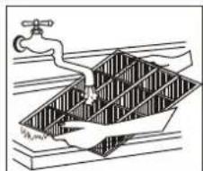
natural_image
Diagram of a water tank with a pipe and submerged object, no text or symbols presentCleaning Your Air Filter
A clogged air filter can reduce the cooling efficiency of your unit and increase operating noise. Make sure to clean the filter once every two weeks (or as necessary) during periods of frequent operation.
- Hold the slot under the front panel, then uplift it outwards, and remove the front panel.
- Pinch the handle under the air filter and make the air filter arched, remove it from the slot from underside to upside(Model A). Grasp the handle of the filter, then slide it downwards to remove the filter(Model B).
- Clean the filter with warm, soapy water. The water should be below 40°C (104°F) to prevent distortion of the filter.
- If your filter has a small air freshening filter, clean this air freshening filter with a hand-held vacuum.
- Rinse the air filter with fresh water, then shake off excess water.
- Dry it in a cool, dry place, and refrain from exposing it to direct sunlight.
If your filter has a small air freshening filter(optional), it can be installed at any of the four positions, install it at the position as you like. Clean it with a hand-held vacuum.


CAUTION
NEVER operate the air conditioner without the air filter, as dust/dirt particles can contribute to equipment failure.
Winter Storage
If you plan to store the air conditioner during the winter, remove it carefully from the window according to the installation instructions. Cover it with plastic or return it to the original carton.
WATER DRAINAGE
The condensed water can be treated as follows:
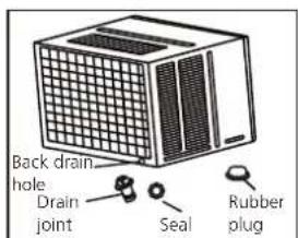
Bot tom drainage (Applicable for the units designed with bottom drain hole only.)
- Remove the rubber plug from the bottom of cabinet(if any)
- Take out the drain pan and screws from accessory.
- Fix the drain pan onto the bottom of cabinet by screws.
- Connect an extension drain hose (locally purchased) to the outlet of drain tray.
NOTE: The bottom drainage will slightly affect cooling performance, but it can reduce the noise caused by spraying the condensed water. For pump heating, the bottom drainage must be chosen.
Back drainage
- Fit the seal onto the drain joint(provided as accessory).
- Insert the drain joint to the back drainage hole, and rotate it by 90° to be well fitted.
- Connect an extension drain hose (locally purchased according to the installation length request) to the drain joint.
- Make sure to plug the bottom drain hole by rubble plug.
NOTE: The back drainage will slightly affect cooling performance, but will reduce the noise caused by spraying the condensed water.



Bottom drainage
Non-drainage
Non-drainage
If you choose non-drainage when cooling, both the bottom and the back drain holes of the unit should be plugged with rubber plugs. The condensed water will be sprayed to condenser, and will improve the cooling performance.
NOTE: When you choose non-drainage, the air conditioner will be perfect cooling efficiency, but big noise may be caused by spraying the condensed water. Please do not choose it if you are sensitive to the noise.
Note on the product
- The rated cooling performance is tested under non-drainage status.
- Make sure that water will not leak from the surrounding area when rubber plug and joint were used. Please seal it in case leakage is found.
INSTALLATION INSTRUCTIONS
Prior to installation
CAUTION: Before installing, remove all packaging from inside the carton, along with any inserts placed into the side louvers.
Step 1: Select the best location
- To avoid vibration and noise, make sure the unit is installed securely and firmly.
- Install the unit where the sunlight does not shine directly on the unit. If the unit receives direct unlight, build an awning to shade the cabinet.
- There should be no obstacle, such as a fence or wall, within 50cm from the back of the cabinet because it will prevent heat radiation of the condenser. Restriction of outside air will greatly reduce the cooling and heating efficiency of the air conditioner.
- Install the unit a little obliquely downward to outside not to leak the condensed water into the room (about 5\~7mm).
- Install the unit with its bottom portion 75\~150cm above the floor level.
- The power cord must be connected to an independent circuit. The yellow/green wire must be grounded.

CAUTION
All side louvers of the cabinet must remain exposed to the outside of the structure.

Option B
Step 2: Remove the front panel and air filter
- Take out the air conditioner from it's packaging.
- Hold the slot under the front panel, then uplift it outwards, and remove the front panel( See Fig. 1)
- Grip the tab on the end of the filter, lift it up, then pull it towards yourself, pull the filter out(see Fig.2)
Step 3: Remove the frame
- Remove two screws at the bottom of the frame.(See Fig. 3)
- Disconnect the coupler plugs and make sure not to interfere with the temperature sensor cable. Hold the left bottom side of the frame, lift it up to unlatch the lower side, remove it toward you (See Fig. 4)
NOTE: For some units the front panel and frame do not install on the machine placed at the back of the unit, step 2 and step 3 do not need.
Step 4: Remove the cabinet
NOTE: There are slight differences on removing the cabinet according to the different models.
Model A:
- Remove one screw securing the chassis fixing bracket, then take down the chassis fixing bracket as shown in Fig.5A.
- Grasp the handle on the chassis and carefully slide the air conditioner out of the cabinet.(see Fig.6)

Remove inserts placed into the side louvers


natural_image
Technical illustration of a modular air conditioning unit with cooling fins and ventilation grilles (no text or symbols)
natural_image
Technical line drawing of a modular air conditioner unit with cooling fins and ventilation grilles (no text or symbols)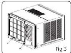
natural_image
Technical illustration of a 3D air conditioning unit with ventilation grilles and cooling fins (no text or symbols)
natural_image
Technical illustration of an air conditioner unit with cooling fins and ventilation grilles (no text or symbols)
natural_image
Technical line drawing of a 3D model of an air conditioning unit (no text or symbols)Model B:
- Remove one screw securing the chassis fixing bracket, then take down the chassis fixing bracket. Remove two screws located on the back of the cabinet as shown in Fig.5B.
- Grasp the handle on the chassis and carefully slide the air conditioner out of the cabinet.(see Fig.6)
Model C:
- Remove four screws located on both sides and the back of the cabinet as shown in Fig.5C.
- Grasp the handle on the chassis and carefully slide the air conditioner out of the cabinet.(see Fig.6)
Model D:
- Remove one screw securing the chassis fixing bracket, then take down the chassis fixing bracket.(see Fig.5D)
- Remove four screws located on both sides and the back of the cabinet as shown in Fig.5D.
- Grasp the handle on the chassis and carefully slide the air conditioner out of the cabinet.(see Fig.6)
Step 5: Install the cabinet
NOTE: Unit may be supported by a solid frame from below or by a hanger from a solid overhead support(not supplied, purchase separately, please contact the dealer).
- When need to drain off water, install the drain plug on the chassis board.
- Prepare the hole in the wall so that the bottom of the cabinet is well supported, the top has minimum clearance and the air inlet louvers have clearance as shown in previous page(Fig. Option A & B). Holes from the outside through to the cavity should be sealed. The cabinet should slop down towards the rear by about 5\~7mm to allow water formed during operation to drain.
- Install the cabinet into the wall and secure. Ensure the foam seals are not damaged. Flash, seal or fill gaps around the inside and outside to provide satisfactory appearance and protection against the weather, insects and rodents. (see Fig.7)

natural_image
Technical line drawings of two modular electronic devices, one with ventilation grilles and the other with a grid-like structure (no text or symbols)
natural_image
Technical line drawing of two modular air conditioning units, one with ventilation grilles and the other with heat sinks (no text or symbols)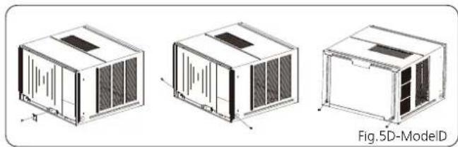
natural_image
Three technical line drawings of a modular air conditioning unit with heat sinks and ventilation grilles, shown from different angles (no text or symbols)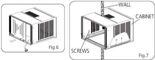
Step 6: Install the unit into the cabinet
- Slide the unit into the cabinet until it is firmly against the rear of the cabinet. Care is required to ensure the foam sealing strips on the cabinet remain in position (See Fig.8).
- Connect the air conditioner to the power and position excess cord length beneath the air conditioner base.
- Engage the chassis fixing brackets into the bottom cabinet rail and secure to the base with the screw provided.
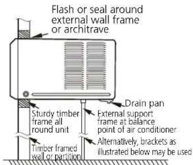
Preferred method of installation into a timber framed wall, partition or window

Alternative method of installation if external support can not be provided

natural_image
Technical line drawing of a mechanical device with ventilation grilles and a base mount (no text or symbols)
natural_image
Technical line drawing of a mechanical device with grid and ventilation slots (no text or symbols)Step 7: Install the frame
- Hook the upper edge of the frame. Then connect the coupler plugs and make sure not to interfere with the temperature sensor cable(see Fig.9).
- Press the both side and lower edge of the frame, and secure it with the two screws at the bottom of the frame.(See Fig. 10)
Step 8: Install the air filter and front panel
- Insert the air filter into the frame's slot from upside to underside. (See Fig. 2)
- Hang the front panel on the frame's buckle, then press the front panel into the frame's slot until you hear a click (see Fig.11).
- Switch unit on. Check for operation of the unit and check for vibration after installation.
- Fit the drain pan to the cabinet and run a drain hose to a suitable location if required.

natural_image
Technical illustration of a modular air conditioner unit with ventilation grilles and cooling fins (no text or symbols)
natural_image
Technical line drawing of a modular air conditioner unit (no text or symbols)NOTE: For the unit with power cord comes out from left side,
please perform the following steps:
- Pull the power cord to the left side straightly(See Fig.a & b).
- Wrap the PVC protecting sheath on the power cord with cable ties in the hole position (see Fig.c).
- Tie up the power cord on the frame (see Fig.d & e) (Applicable for units with body dimension of 600mm*380mm*560mm only)
- Install the frame and front panel according to the above Step 6 and Step 7.


natural_image
3D diagram of a rectangular device with internal structure and ventilation slots, labeled Fig.d (no text or symbols on the device itself)
TROUBLE SHOOTING

SAFETY PRECAUTIONS
If ANY of the following conditions occurs, turn off your unit immediately!
• The power cord is damaged or abnormally warm
• You smell a burning odor
• The unit emits loud or abnormal sounds
- A power fuse blows or the circuit breaker frequently trips
• Water or other objects fall into or out of the unit
DO NOT ATTEMPT TO FIX THESE YOURSELF! CONTACT AN AUTHORIZED SERVICE PROVIDER IMMEDIATELY!
Common Issues
The following problems are not a malfunction and in most situations will not require repairs.
Issue Possible Causes
| Unit does not turn on when pressing ON/OFF button | Wall plug disconnected. Push plug firmly into wall outlet. |
| House fuse blown or circuit breaker tripped. Replace fuse with time delay type or reset circuit breaker. | |
| Selector Control in OFF position. Turn selector to the desired FAN or COOL setting. | |
| Unit turned off by moving thermostat to a higher number and then immediately turning back to a colder number. Wait approximately 3 minutes. Listen for compressor to start. | |
| Unit turned off and then on too quickly. Turn unit off and wait for 3 minutes before restarting. | |
| Thermostat set too low. Adjust thermostat to higher number for cooling. | |
| Air from unit does not feel cold enough | Turn selector to a higher COOL position. |
| Thermostat set too warm. Set thermostat to colder temperature. | |
| Room temperature below 18°C(64°F). Cooling may not occur until room temperature rise above 18 C(64 F). | |
| Temperature sensing tube touching cold coil, located behind air filter. Straighten tube away from coil. | |
| Air conditioner cooling, but room is too warm-ice forming on cooling coil behind decorative front | Outdoor temperature below 18°C(64°F). To defrost the coil, set selector to FAN position. Then, set thermostat to warmer position. |
| Air filter may be dirty. Clean filter. Refer to Care and Maintenance section. To defrost, set selector to FAN. | |
| Thermostat set too cold for night-time cooling. To defrost the coil, set selector to a FAN position. Then, set thermostat to a warmer position. | |
| Air conditioner cooling, but room is too warm-ice forming on cooling coil behind decorative front | Dirty air filter- air restricted. Clean air filter. Refer to Care and Maintenance section. |
| Thermostat set too warm. Turn thermostat clockwise to a colder setting. | |
| All directional louvers positioned improperly. Position louvers for better air distribution. | |
| Front of units is blocked by drapes, blinds, furniture, etc. - restricts air distribution. Clear blockage in front of unit. | |
| Doors, windows, registers, etc. Open- cold air escapes. Close doors, windows, registers. | |
| Unit recently turned on in hot room. Allow additional time to remove "Stored heat" from walls, ceiling, floor and furniture. | |
| Air conditioner turns on and off rapidly | Dirty air filter - air restricted. Clean air filter. |
| Outside temperature extremely hot. Set to high cool to bring air past cooling coils more frequently. |
Issue Possible Causes
| Noise when unit is cooling | Air movement sound. This is normal. If too loud, turn selector to lower FAN setting. |
| Sound of fan hitting water-moisture removal system. This is normal when humidity is high. Close doors, windows and registers. | |
| Window vibration - poor installation. Refer to installation instructions or check with installer. | |
| Water dripping INSIDE when unit is cooling | Improper installation. Tilt air conditioner slightly to the outside to allow water drainage. Refer to installation instructions - check with installer. |
| Water dripping OUTSIDE when unit is cooling | Unit removing large quantity of moisture from humid room. This is normal during excessively humid days. |
SPECIFICATIONS
Unit dimensions: Choose the right cable size
| MODEL(But/h) | BODY DIMENSION(WxHxD)(mm) |
| 5000~6000 | 445x320x415 |
| 450x346x535 | |
| 7000~9000 | 451x346x535 |
| 451x346x585 | |
| 451x350x675 | |
| 9000~12000 | 451x346x585 |
| 451x350x675 | |
| 560x400x640 | |
| 600x380x560 | |
| 15000~24000 | 660x428x680 |
| 660x428x780 |
Note: For the different customization requirements, the depth of the panel may be slightly different. So the dimension of "D" is for reference only.
The size of the power supply cable, signal cable, fuse, and switch needed is determined by the maximum current of the unit. The maximum current is indicated on the nameplate located on the side panel of the unit. Refer to this nameplate to choose the right cable, fuse, or switch. Minimum nominal cross-sectional area of conductors:
| Rated Current of Appliance (A) Nominal Cross-Sectional Area (mm2) | |
| >3 and ≤ 6 0.75 | |
| >6 and ≤ 10 | 1 |
| >10 and ≤ 16 | 1.5 |
| >16 and ≤ 25 | 2.5 |
| >25 and ≤ 32 | 4 |
| >32 and ≤ 40 | 6 |
NOTE: TO be in compliance EN61000-3-11, the product MWT2F-21CM-QB4 shall be connected only to a supply of the system impedance: IZsysI=0.156 ohms or less; the product MWT2F1-22CM-QB4 shall be connected only to a supply of the system impedance: IZsysI=0.132 ohms or less; the product MWT2F1-22CM-QB8 shall be connected only to a supply of the system impedance: IZsysI=0.077 ohms or less. Before connect the product to public power network, please consult your local power supply authority to ensure the power network meet above requirement.
安全須知
操作和安裝前請閱讀安全須知
natural_image
Simple line drawing of an open book with no text or symbols visible
natural_image
Technical line drawing of a rectangular electronic device with ventilation grilles and a paper clip, labeled A (no text or symbols on the diagram itself)
natural_image
Diagram of a white air conditioner unit with ventilation grilles and labeled component B (no text or symbols beyond label)風向控制
- 水準氣流調節
對於帶手動控制杆的機型(手動)
natural_image
Line drawing of a portable air conditioner unit with ventilation grilles and airflow arrows (no text or symbols)
natural_image
Diagram of an air conditioner unit labeled A型, showing internal airflow path (no text or symbols beyond label)
natural_image
Technical line drawing of a mechanical component with no visible text or symbols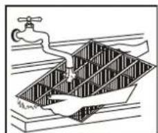
natural_image
Illustration of a faucet spraying water into a water tank (no text or symbols)清潔空氣過濾器
natural_image
Technical illustration of a modular air conditioner unit with ventilation grilles and cooling fins (no text or symbols)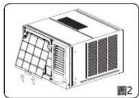
natural_image
Technical line drawing of a modular air conditioner unit with ventilation grilles and fan array (no text or symbols)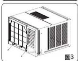
natural_image
Technical line drawing of a modular air conditioner unit with ventilation grilles and cooling fins (no text or symbols)
natural_image
Technical line drawing of a modular air vent or enclosure with ventilation grilles and control panel (no text or symbols)
natural_image
Technical line drawing of a 5A-A-type industrial enclosure or housing unit (no text or symbols on the diagram itself)B型:
natural_image
Technical line drawings of two industrial cooling units labeled 5B-B and a smaller unit, shown from front and side views (no text or symbols on the diagram itself)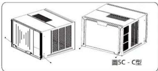
natural_image
Technical line drawings of two industrial air ducts labeled '5C-C型' (Model 5C), showing internal structure and mounting brackets (no text or symbols beyond label)
natural_image
Three technical line drawings of a 3D air conditioning unit (no text or symbols on the diagram itself)
natural_image
Technical line drawing of a computer unit with ventilation grilles and cooling fan (no text or symbols)
natural_image
Line drawing of a modular air conditioner unit with ventilation grilles and cooling fan (no text or symbols)
natural_image
Technical line drawing of a 3D air conditioner unit with ventilation grilles and cooling fins (no text or symbols)第7步:安装框架
natural_image
Technical illustration of a modular air conditioner unit with ventilation grilles and cooling fins (no text or symbols)
natural_image
Technical diagram of a modular air conditioner unit with labeled components (no text or symbols beyond labels)natural_image
Illustration of a rectangular electronic device with ventilation slots and a label '圖d' (Figure d) in the corner.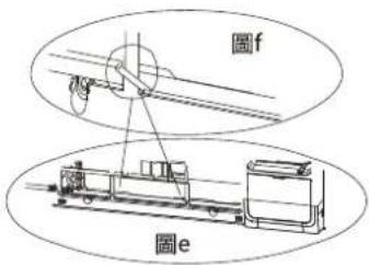
故障排除

安全須知
購買日期 Date of Purchase:
單據編號 Invoice No.:
The product specifications may be changed without prior notice.
Please contact customer service for details if necessary.
說明書內容以英文版本為準
If there is any inconsistency or ambiguity
between the English version and the Chinese version, the English version shall prevail.

保養登記
Warranty Registration
於網上登記新產品保養 Register your product online
www.dchtoolbox.com

Gilman
since 1841

DCHToolBox
大昌行電器維修中心
4/F, DCH Building, 20 Kai Cheung Road, Kowloon Bay, Hong Kong
客戶服務熱線 Customer Service Hotline: (852) 8210 8210
- PHILCO®
- IMPORTANT NOTE:
- WARNING
- Transportation, marking and storage for units
- Table of Contents
- Disposal Requirement in Hong Kong
- Read Before Operation and Installation
- Incorrect installation due to ignoring instructions can cause serious damage or injury.
- CAUTION
- WARNINGS FOR PRODUCT USE
- CLEANING AND MAINTENANCE WARNINGS
- ELECTRICAL WARNINGS
- TAKE NOTE OF FUSE SPECIFICATIONS
- WARNINGS FOR PRODUCT INSTALLATION
- WARNING for Using R32 Refrigerant
- Transport of equipment containing flammable refrigerants
- Marking of equipment using signs
- 3.Disposal of equipment using flammable refrigerants
- 4.Storage of equipment/appliances
- 5.Storage of packed (unsold) equipment
- 6.Information on servicing
- Repairs to sealed components
- Repair to intrinsically safe components
- 9.Cabling
- Detection of flammable refrigerants
- 11.Leak detection methods
- Removal and evacuation
- Charging procedures
- 14.Decommissioning
- 15.Labelling
- 16.Recovery
- Operating temperature
- To further optimize the performance of your unit, do the following:
- UNIT PARTS IDENTIFICATION
- Accessories
- Vent Control
- OPERATING INSTRUCTIONS
- POWER:
- MODE:
- ▲ TEMPERATURE SETTINGS UP:
- ▼ TEMPERATURE SETTINGS DOWN:
- FAN:
- SWING: (on some models)
- Wireless Operation: (on some models)
- TIMER: (on some models)
- DRY: (on some models)
- COOL :
- HEAT: (on some models)
- AUTO:
- SLEEP :
- Turbo function (on some models)
- UV function (on some models)
- ECO function(on some models)
- LED Display:
- Shows Error codes:(Inverter Type)
- Shows Error codes:(Fixed-speed Type)
- Operation panel cover (some units)
- For the units with operation panel cover (see the left figures of A & B)
- Air direction control
- • Horizontal airflow adjustment
- • Vertical airflow adjustment(Manually)
- CARE AND MAINTENANCE
- BEFORE CLEANING OR MAINTENANCE
- ALWAYS TURN OFF YOUR AIR CONDITIONER SYSTEM AND DISCONNECT ITS POWER SUPPLY BEFORE CLEANING OR MAINTENANCE.
- Cleaning Your Unit
- IMPORTANT
- Cleaning Your Air Filter
- Winter Storage
- WATER DRAINAGE
- Back drainage
- Non-drainage
- Note on the product
- INSTALLATION INSTRUCTIONS
- Prior to installation
- CAUTION: Before installing, remove all packaging from inside the carton, along with any inserts placed into the side louvers.
- Step 1: Select the best location
- Step 2: Remove the front panel and air filter
- Step 3: Remove the frame
- Step 4: Remove the cabinet
- Model A:
- Model B:
- Model C:
- Model D:
- Step 5: Install the cabinet
- Step 6: Install the unit into the cabinet
- Step 7: Install the frame
- Step 8: Install the air filter and front panel
- NOTE: For the unit with power cord comes out from left side,
- TROUBLE SHOOTING
- SAFETY PRECAUTIONS
- DO NOT ATTEMPT TO FIX THESE YOURSELF! CONTACT AN AUTHORIZED SERVICE PROVIDER IMMEDIATELY!
- Common Issues
- SPECIFICATIONS
- Unit dimensions: Choose the right cable size
- 安全須知
- 風向控制
- - 水準氣流調節
- 清潔空氣過濾器
- B型:
- 第7步:安装框架
- 故障排除
Brand : Philco
Model : PVR07R
Category : Air conditioner