
Chill Switch - Guitar effect pedal Electro Harmonix - Free user manual and instructions
Find the device manual for free Chill Switch Electro Harmonix in PDF.


| Product Type | Momentary Line Selector |
| Brand | Electro Harmonix |
| Model | Chill Switch |
| Power Supply | 9V battery or 9.6VDC 200mA adapter (center negative) |
| Current Draw | 12.5 mA |
| Input Impedance (INPUT) | 2.2 MΩ |
| Input Impedance (RETURN) | 2.2 MΩ |
| Output Impedance (AMP) | 220 Ω |
| Output Impedance (SEND) | 220 Ω |
| LED Indicator | Reflects signal at AMP jack; OFF = direct input, ON = effects loop or mute (Kill Setup) |
| Controls | Footswitch, ENGAGE rotary switch (THRU/FX), SEND rotary switch (FSW/ON) |
| Setups | Kill Setup (mute/unmute) and Line Selector Setup (dry/effects loop) |
| Battery Replacement | Remove 4 bottom screws, replace 9V battery; avoid touching circuit board |
| Warranty | 1 year from purchase for original buyer from authorized retailer; register at ehx.com |
| Dimensions | Not specified in manual |
| Weight | Not specified in manual |
Frequently Asked Questions - Chill Switch Electro Harmonix
User questions about Chill Switch Electro Harmonix
0 question about this device. Answer the ones you know or ask your own.
Ask a new question about this device
Download the instructions for your Guitar effect pedal in PDF format for free! Find your manual Chill Switch - Electro Harmonix and take your electronic device back in hand. On this page are published all the documents necessary for the use of your device. Chill Switch by Electro Harmonix.
USER MANUAL Chill Switch Electro Harmonix
electro-harmonix CHILLSWITCH
MOMENTARY LINE SELECTOR
Congratulations on your purchase of the Electro-Harmonix CHILLSWITCH.
- KILL SETUP -
In this setup, the CHILLSWITCH allows you to quickly switch between mute and unmute by pressing the footswitch, resulting in a hard rhythmic tremolo effect.

flowchart
graph LR
    A["Speaker"] --> B["KILLSHITCH"]
    B --> C["ENGAGE"]
    B --> D["SEND"]
    B --> E["AMP"]
    B --> F["INPUT"]
    C --> G["RETURN"]
    D --> H["SEND"]
    F --> I["OUTPUT"]
INPUT JACK – Connect to the output of your instrument or another effects pedal
SEND JACK – Disconnect
RETURN JACK – Disconnect
AMP JACK – Connect to the input of you amplifier or another effects pedal
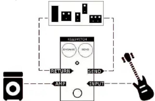
- LINE SELECTOR SETUP -
In this setup, the CHILLSWITCH allows you to quickly switch between an effects loop and your dry signal by pressing the footswitch. Depending on the effects in the loop, it could trigger a burst of distortion, or perhaps a foot-controlled delay feedback... the possibilities are endless!
flowchart
graph TD
    A["Speaker"] --> B["KELLSWITCH"]
    B --> C["ENGAGE"]
    B --> D["SEND"]
    B --> E["OUTPUT"]
    B --> F["AMP"]
    B --> G["SEND"]
    B --> H["INPUT"]
INPUT JACK – Connect to the output of your instrument or another effects pedal
SEND JACK – Connect to the input of your effects loop
RETURN JACK – Connect to the output of your effects loop
AMP JACK – Connect to the input of you amplifier or another effects pedal
- LED INDICATOR -
In either setup, the LED reflects the signal present at the AMP jack.
- LED OFF – The AMP jack outputs the original INPUT signal
LED ON – The AMP jack outputs the signal from the effects loop (or no signal, in Kill Setup)
- "ENGAGE" ROTARY SWITCH -
The ENGAGE rotary switch affects how the footswitch controls the AMP output.
- KILL SETUP -
ENGAGE: THRU

flowchart
graph TD
    A["ATTU"] --> B["SEND"]
    B --> C["AMP"]
    C --> D["IN"]
    D --> E["Feedback Loop"]
    E --> F["RETURN"]
    F --> G["SEND"]
    G --> H["ATTU"]
While footswitch is pressed, the INPUT signal travels directly to the AMP output

flowchart
graph TD
    A["KILLSWITCH"] --> B["ENGAGE THRU"]
    A --> C["SEND"]
    B --> D["AMP"]
    C --> E["X"]
    C --> F["IN"]
    D --> G["Return"]
    E --> H["Send"]
While footswitch is released, the AMP output is muted
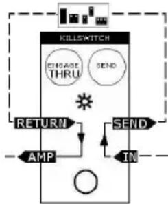
- LINE SELECTOR SETUP -
ENGAGE: THRU

flowchart
graph TD
    A["KILLSWITCH"] --> B["ENGAGE THRU"]
    B --> C["SEND"]
    C --> D["AMP"]
    D --> E["IN"]
    E --> F["Feedback Loop"]
    F --> G["Return"]
    G --> A
While footswitch is pressed, the INPUT signal travels directly to the AMP output*
flowchart
graph TD
    A["KILLSWITCH"] --> B["CHASE THRU"]
    A --> C["SEND"]
    B --> D["AMP"]
    C --> E["IN"]
    D --> F["RETURN"]
    E --> F
    F --> G["Sun icon"]
While footswitch is released, the INPUT signal travels through the FX Loop
*See "SEND" ROTARY SWITCH section
- KILL SETUP -
ENGAGE: FX

flowchart
graph TD
    A["KILLSWITCH"] --> B["ENSAGE FX"]
    A --> C["SEND"]
    B --> D["AMP"]
    C --> D
    D --> E["X"]
    E --> F["INPUT"]
    F --> G["SEND"]
    G --> H["RETURN"]
While footswitch is pressed, the AMP output is muted
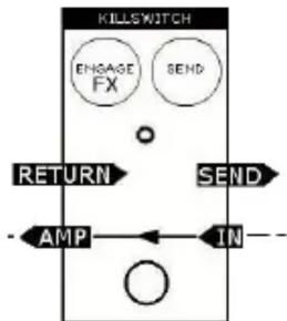
While footswitch is released, the INPUT signal travels directly to the AMP output
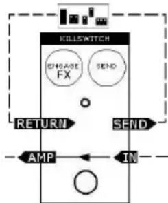
- LINE SELECTOR SETUP -
ENGAGE: FX

flowchart
graph TD
    A["KILLSWITCH"] --> B["ENGAGE FX"]
    A --> C["SEND"]
    B --> D["INPUT"]
    C --> D
    D --> E["RETURN"]
    E --> F["AMP"]
    F --> G["SEND"]
    G --> H["IN"]
    H --> I["OUTPUT"]
    I --> J["Feedback to END"]
While footswitch is pressed, the INPUT signal travels through the FX Loop
flowchart
graph TD
    A["KILLSWITCH"] --> B["ENGAGE FX"]
    A --> C["SEND"]
    B --> D["RETURN"]
    C --> E["SEND"]
    D --> F["AMP"]
    E --> G["IN"]
While footswitch is released, the INPUT signal travels directly to the AMP output*
*See "SEND" ROTARY SWITCH section
- "SEND" ROTARY SWITCH -
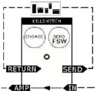
The SEND rotary switch allows you to choose between routing the INPUT signal to the SEND jack at all times (ON position) or only when the FX Loop is active (FSW position). The setting of the SEND switch is ignored when using the KILL setup.
SEND: FSW
flowchart
graph TD
    A["INTL SWITCH"] --> B["ENGAGE"]
    A --> C["SEND FSW"]
    B --> D["AMP"]
    C --> E["IN"]
The INPUT signal only travels to the SEND jack when the FX Loop is activated.
Use this setting with an envelope-triggered effect (auto-wah): The CHILLSWITCH will reset the envelope sweep with each press of the footswitch
SEND: ON

flowchart
graph TD
    A["INTL SWITCH"] --> B["ENGAGE"]
    A --> C["SEND ON"]
    B --> D["RETURN"]
    C --> E["SEND"]
    D --> F["AMP"]
    E --> G["IN"]
The INPUT signal always travels to the Send jack
Use this setting with a delay effect: The CHILLSWITCH will continuously send the INPUT signal to the delay
- POWER -
Power from the internal 9-volt battery is activated by plugging into the INPUT jack. The input cable should be removed when the unit is not in use to avoid running down the battery. The barrel connector on the front of the CHILLSWITCH is for a 9-volt battery elimina capable of delivering at least 25 mA of current. The optional 9V power supply from Electro-Harmonix is 9.6DC-200BI (same as used by Boss™ & Ibanez™) 9.6 Volts DC 200mA. The power supply must have a barrel connector with center negative. The unit's battery may be left in or taken out when the eliminator is in use. The actual current draw of the CHILLSWITCH is 12.5 mA.
To change the 9-volt battery, remove the 4 screws on the bottom of the CHILLSWIT( Once the screws are removed, take off the bottom plate and change the battery. Please do not touch the circuit board or you risk damaging a component.
Input Jack Impedance
INPUT - 2.2 MΩ
RETURN - 2.2 MΩ
Output Jack Impedance
AMP - 220 Ω
SEND - 220 Ω
- WARRANTY INFORMATION -
Please register online at http://www.ehx.com/product-registration or complete and return the enclosed warranty card within 10 days of purchase. Electro-Harmonix will repair or replace, at its discretion, a product that fails to operate due to defects in materials or workmanship for a period of one year from date of purchase. This applies only to original purchasers who have bought their product from an authorized Electro-Harmonix retailer. Repaired or replaced units will then be warranted for the unexpired portion of the original warranty term.
If you should need to return your unit for service within the warranty period, please contact the appropriate office listed below. Customers outside the regions listed below, please contact EHX Customer Service for information on warranty repairs at info@ehx.com or +1-718-937-8300. USA and Canadian customers: please obtain a Return Authorization Number (RA#) from EHX Customer Service before returning your product. Include with your returned unit: a written description of the problem as well as your name, address, telephone number, e-mail address, and RA#; and a copy of your receipt clearly showing the purchase date.
United States & Canada
EHX CUSTOMER SERVICE
ELECTRO-HARMONIX
c/o NEW SENSOR CORP.
47-50 33RD STREET
LONG ISLAND CITY, NY 11101
Tel: 718-937-8300
Email: info@ehx.com
Europe
JOHN WILLIAMS
ELECTRO-HARMONIX UK
13 CWMDONKIN TERRACE
SWANSEA SA2 0RQ
UNITED KINGDOM
Tel: +44 179 247 3258
Email: electroharmonixuk@virginmedia.com
This warranty gives a purchaser specific legal rights. A purchaser may have even greater rights depending upon the laws of the jurisdiction within which the product was purchased.
To hear demos on all EHX pedals visit us on the web at www.ehx.com
Email us at info@ehx.com


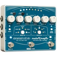
Brand : Electro Harmonix
Model : Chill Switch
Category : Guitar effect pedal