
DS-PWA96-DB-WB - Alarm Hikvision - Free user manual and instructions
Find the device manual for free DS-PWA96-DB-WB Hikvision in PDF.


| Product Type | Wireless Alarm Control Panel |
| Model | DS-PWA96-DB-WB |
| Brand | Hikvision |
| Wireless Technology | Tri-X 2-way wireless with AES-128 encryption and FHSS |
| Primary Transmission Path | LAN / Wi-Fi |
| Secondary Transmission Path | GPRS or 3G/4G LTE |
| Backup Battery | 4520 mAh lithium |
| Standby Time | 12 hours |
| Event Log Capacity | Mandatory 1000, total 5000 |
| ARC Signaling | ATS Category DP2 |
| Supported Protocols | SIA-DC09, Contact ID, ISUP 5.0 |
| Security Grade | Grade 2 (EN 50131) |
| Environmental Class | Class II (EN 50131) |
| Configuration Methods | Web client, Hik-Connect app, Hik-Partner Pro app, Convergence Cloud |
| Voice Guide | Yes (alerts, status, operation prompts) |
| Notification Options | Push messages, phone calls, email with video clips |
| Alarm Reporting to ARC | Yes (SIA-DC09, Contact ID) |
| Video Support | Live view via Hik-Connect, alarm video clips via email, Hik-Partner Pro, Hik-Connect |
| Tamper Protection | Tamper alarm on lid opening |
| Firmware Upgrade | Via Hik-Partner Pro or web client |
Frequently Asked Questions - DS-PWA96-DB-WB Hikvision
User questions about DS-PWA96-DB-WB Hikvision
0 question about this device. Answer the ones you know or ask your own.
Ask a new question about this device
Download the instructions for your Alarm in PDF format for free! Find your manual DS-PWA96-DB-WB - Hikvision and take your electronic device back in hand. On this page are published all the documents necessary for the use of your device. DS-PWA96-DB-WB by Hikvision.
USER MANUAL DS-PWA96-DB-WB Hikvision
- This Document includes instrucons for using and managing the Product. Pictures, charts, images and all other informaon hereinaer are for descripon and explanaon only.
- The informaon contained in the Document is subject to change, without noce, due to rmware updates or other reasons. Please nd the latest version of the Document at the Hikvision website (hps://www.hikvision.com). Unless otherwise agreed, Hangzhou Hikvision Digital Technology Co., Ltd. or its aliates (hereinaer referred to as "Hikvision") makes no warranes, express or implied.
- Please use the Document with the guidance and assistance of professionals trained in supporting the Product.
About this Product
This product can only enjoy the aer-sales service support in the country or region where the purchase is made.
Acknowledgment of Intellectual Property Rights
- Hikvision owns the copyrights and/or patents related to the technology embodied in the Products described in this Document, which may include licenses obtained from third pares.
- Any part of the Document, including text, pictures, graphics, etc., belongs to Hikvision. No part of this Document may be excerpted, copied, translated, or modified in whole or in part by any means without written permission.
- HIKVISION and other Hikvision's trademarks and logos are the properes of Hikvision in various jurisdicons.
- Other trademarks and logos menoned are the properes of their respective owners.
LEGAL DISCLAIMER
- TO THE MAXIMUM EXTENT PERMITTED BY APPLICABLE LAW, THIS DOCUMENT AND THE PRODUCT DESCRIBED, WITH ITS HARDWARE, SOFTWARE AND FIRMWARE, ARE PROVIDED "AS IS" AND "WITH ALL FAULTS AND ERRORS". HIKVISION MAKES NO WARRANTIES, EXPRESS OR IMPLIED, INCLUDING WITHOUT LIMITATION, MERCHANTABILITY, SATISFACTORY QUALITY, OR FITNESS FOR A PARTICULAR PURPOSE. THE USE OF THE PRODUCT BY YOU IS AT YOUR OWN RISK. IN NO EVENT WILL HIKVISION BE LIABLE TO YOU FOR ANY SPECIAL, CONSEQUENTIAL, INCIDENTAL, OR INDIRECT DAMAGES, INCLUDING, AMONG OTHERS, DAMAGES FOR LOSS OF BUSINESS PROFITS, BUSINESS INTERRUPTION, OR LOSS OF DATA, CORRUPTION OF SYSTEMS, OR LOSS OF DOCUMENTATION, WHETHER BASED ON BREACH OF CONTRACT, TORT (INCLUDING NEGLIGENCE), PRODUCT LIABILITY, OR OTHERWISE, IN CONNECTION WITH THE USE OF THE PRODUCT, EVEN IF HIKVISION HAS BEEN ADVISED OF THE POSSIBILITY OF SUCH DAMAGES OR LOSS.
- YOU ACKNOWLEDGE THAT THE NATURE OF THE INTERNET PROVIDES FOR INHERENT SECURITY RISKS, AND HIKVISION SHALL NOT TAKE ANY RESPONSIBILITIES FOR ABNORMAL OPERATION,
PRIVACY LEAKAGE OR OTHER DAMAGES RESULTING FROM CYBER-ATTACK, HACKER ATTACK, VIRUS INFECTION, OR OTHER INTERNET SECURITY RISKS; HOWEVER, HIKVISION WILL PROVIDE TIMELY TECHNICAL SUPPORT IF REQUIRED.
- YOU AGREE TO USE THIS PRODUCT IN COMPLIANCE WITH ALL APPLICABLE LAWS, AND YOU ARE SOLELY RESPONSIBLE FOR ENSURING THAT YOUR USE CONFORMS TO THE APPLICABLE LAW. ESPECIALLY, YOU ARE RESPONSIBLE, FOR USING THIS PRODUCT IN A MANNER THAT DOES NOT INFRINGE ON THE RIGHTS OF THIRD PARTIES, INCLUDING WITHOUT LIMITATION, RIGHTS OF PUBLICITY, INTELLECTUAL PROPERTY RIGHTS, OR DATA PROTECTION AND OTHER PRIVACY RIGHTS. YOU SHALL NOT USE THIS PRODUCT FOR ANY PROHIBITED END-USES, INCLUDING THE DEVELOPMENT OR PRODUCTION OF WEAPONS OF MASS DESTRUCTION, THE DEVELOPMENT OR PRODUCTION OF CHEMICAL OR BIOLOGICAL WEAPONS, ANY ACTIVITIES IN THE CONTEXT RELATED TO ANY NUCLEAR EXPLOSIVE OR UNSAFE NUCLEAR FUEL-CYCLE, OR IN SUPPORT OF HUMAN RIGHTS ABUSES.
- IN THE EVENT OF ANY CONFLICTS BETWEEN THIS DOCUMENT AND THE APPLICABLE LAW, THE LATTER PREVAILS.
© Hangzhou Hikvision Digital Technology Co., Ltd. All rights reserved.
Symbol Convenons
The symbols that may be found in this document are dened as follows.
| Symbol | Descripon |
 Danger Danger | Indicates a hazardous situaon which, if not avoided, will or could result in death or serious injury. |
 Cauon Cauon | Indicates a potenally hazardous situaon which, if not avoided, could result in equipment damage, data loss, performance degradaon, or unexpected results. |
 Note Note | Provides additional informaon to emphasize or supplement important points of the main text. |

Note
- Please update rmware to the latest version.
- For installers, it is recommended to install and maintain devices via Hik-Partner Pro.
Regulatory Informaon
EN 50131-1:2006+A1:2009+A2:2017+A3:2020
EN 50131-3:2009
EN 50131-6:2017+A1:2021
EN 50131-5-3:2017
EN 50131-10:2014
EN 50136-2: 2013
SSF 1014
Security Grade (SG): 2
Environmental Class (EC) : II
Larmklass R, Miljöklass II
Cered by KIWA
SBSC
kiwa
i Note EN50131 compliance labeling should be removed if non-compliant conguraons are used.
EU Conformity Statement
 | This product and - if applicable - the supplied accessories too are marked with "CE" and comply therefore with the applicable harmonized European standards listed under the EMC Directive 2014/30/EU, RE Directive 2014/53/EU,the RoHS Directive 2011/65/EU |
 | 2012/19/EU (WEEE directive): Products marked with this symbol cannot be disposed of as unsorted municipal waste in the European Union. For proper recycling, return this product to your local supplier upon the purchase of equivalent new equipment, or dispose of it at designated collecon points. For more informaon see: www.recyclethis.info |
 | Regulaon (EU) 2023/1542(Baery Regulaon): This product contains a baery and it is in conformity with the Regulaon (EU) 2023/1542. The baery cannot be disposed of as unsorted municipal waste in the European Union. See the product documentaon for specic baery informaon. The baery is marked with this symbol, which may include leering to indicate cadmium (Cd), or lead (Pb). For proper recycling, return the baery to your supplier or to a designated collecon point. For more informaon see: www.recyclethis.info.According to the Baeries and Accumulators (Placing on the Market) Regulaons 2008 and the Waste Baeries and Accumulators Regulaons 2009: This product contains a baery that cannot be disposed of as unsorted municipalwaste in the United Kingdom. See the product documentaon for speci baery informaon. The baery is marked with this symbol, which may include leering to indicate cadmium (Cd), lead (Pb), or mercury (Hg). For proper recycling, return the baery to your supplier or to a designated collecon point. For more informaon see: www.recyclethis.info. |
 | FCC InformaonPlease take aenon that changes or modicaon not expressly approved by the party responsible for compliance could void the user's authority to operate the equipment.FCC compliance: This equipment has been tested and found to comply with the limits for a Class B digital device, pursuant to part 15 of the FCC Rules. These limits are designed to provide reasonable protecon against harmful interference in a residenal installaon. This equipment generates, uses and can radiate radio frequency energy and, if not installed and used in accordance with the instrucons, may cause harmful interference to radio communicaons. However, there is no guarantee that interference will not occur in a parcular installaon. If this equipment does cause harmful interference to radio or television recepon, which can be determined by turning the equipment o and on, the user is encouraged to try to correct the interference by one or more of the following measures:-Reorient or relocate the receiving antenna.-Increase the separaon between the equipment and receiver.-Connect the equipment into an outlet on a circuit dierent from that to which the receiver is connected.-Consult the dealer or an experienced radio/TV technician for help.This equipment should be installed and operated with a minimum distance 20cm between the radiator and your body.FCC CondionsThis device complies with part 15 of the FCC Rules. Operaon is subject to the following two condions:1. This device may not cause harmful interference.2. This device must accept any interference received, including interference that may cause undesired operaon. |
Contents
Chapter 1 Installaon Instrucon ......9
1.1 Typical Scene 9
1.2 Precauon....9
1.3 Installaon FAQ....10
Chapter 2 Introducon....11
Chapter 3 Start Up....14
3.1 Authority Management .... 14
3.2 Acvaon....15
3.2.1 Acvaon with LAN/SIM(4G/GPRS)....15
3.2.2 Acvaon with Wi-Fi....16
3.3 Unbind the Device....22
3.3.1 Unbind the Device from Your Own Account....22
3.3.2 Unbind the Device from Another Account....22
Chapter 4 User Management....25
4.1 User Management....25
4.1.1 Invite the Administrator 25
4.1.2 Cancel Installer Access ...... 26
4.1.3 Add an Operator....27
4.1.4 Invite the Installer 28
4.2 Access Entries 29
Chapter 5 Conguraon ....30
5.1 Set-up with Hik-Partner Pro....30
5.1.1 Use the Hik-Partner Pro APP....30
5.1.2 Use the Hik-Partner Pro Portal .... 53
5.2 Set-up with Hik-Connect 57
5.3 Set-up with the Web Client....83
5.3.1 User Management....84
5.3.2 Area Management 86
5.3.3 Device Management 87
5.3.3 System 99
5.3.4 Maintenance and Security 116
5.4 Report to ARC (Alarm Receiving Center)....121
Setup ATS in Transceiver of Receiving Center....121
Setup ATS in Transceiver of the Panel 122
Signaling Test....123
Chapter 6 General Operaons .... 125
6.1 Arming 125
6.2 Disarming....126
6.3 SMS Control 126
A. Trouble Shoong....127
A.1 Communicaon Fault....127
A.1.1 IP Conict 127
A.1.2 Web Page is Not Accessible....127
A.1.3 Hik-Connect is Oine 127
A.1.4 Network Camera Drops o Frequently....127
A.1.5 Failed to Add Device on APP 127
A.1.6 Alarm Informaon is Not Reported to APP/4200/Alarm Center....128
A.2 Mutual Exclusion of Funcons ....128
A.2.1 Unable to Enter Registraon Mode 128
A.3 Zone Fault....128
A.3.1 Zone is Oine 128
A.3.2 Zone Tamper-proof....128
A.3.3 Zone Triggered/Fault 128
A.4 Problems While Arming....129
A.4.1 Failure in Arming (When the forced arming is not enabled) 129
A.5 Operaonal Failure 129
A.5.1 Failed to Enter the Test Mode....129
A.5.2 The Silence Alarm Operaon on the Panel Does Not Produce the Silence Alarm Report 129
A.6 Mail Delivery Failure....129
A.6.1 Failed to Send Test Mail 129
A.6.2 Failed to Send Mail during Use....130
A.6.3 Failed to Send Mails to Gmail....130
A.6.4 Failed to Send Mails to QQ or Foxmail 130
A.6.5 Failed to Send Mails to Yahoo....130
A.6.6 Mail Conguraon....131
B. Input Types .... 132
C. Output Types ...... 135
D. Event Types .... 136
E. Access Levels....137
F. Signalling....139
Detecon of ATP/ATS Faults....139
ATS Category....139
G. SIA and CID Code 140
H. User Privacy Statement.... 156
I. Detector Zone Types....157
Chapter 1 Installaon Instrucon
1.1 Typical Scene
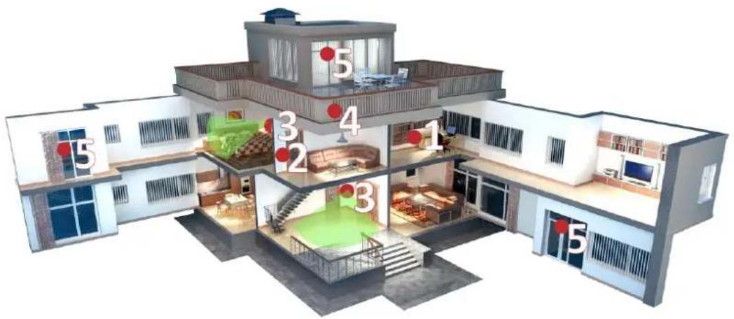
Figure 1-1. Typical Scene
Typical installaon locaon of devices:
- AX PRO Control Panel
- Repeater
- PIR Detector
- Sounder
- Magnec Detector
1.2 Precauon
- Avoid installing the device on metal surfaces.
- Avoid placing the device directly on the ground.
- The device is not allowed to be wrapped in metal.
- Avoid obstrucons within 50 cm around the device, except for the installaon surface.
- The repeater needs to be installed between the control panel and the peripheral.
-
Check the signal strength before installaon and it is recommended to install the device at the green indicator locaon. (Do not wrap the detector with your hands when checking the signal strength.)
-
Vercal installaon is recommended for devices.
1.3 Installaon FAQ
Queson 1:
Why is the signal normal during installaon, but worse in actual use?
Answer:
Check whether the working environment changes during installaon and actual use. Such as obstrucon caused by closed doors and windows.
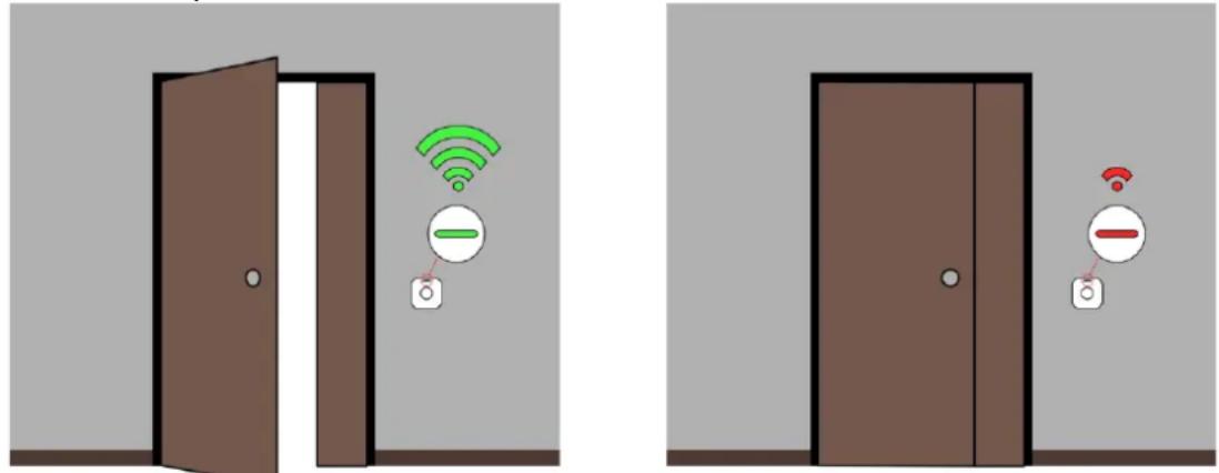
Figure 1-2. Installaon FAQ
Queson 2:
Aer the installaon is complete, the peripheral is oine.
Answer:
- Adjust the posion of the control panel and check whether the signal strength is suitable for installaon.
- Install a repeater between the ofine peripheral and the control panel.
- Check whether to install devices according to the precautions.
Chapter 2 Introducon
AX PRO is a wireless alarm system designed to protect premises required for proper protecon from intrusion alarm. It supports LAN /Wi-Fi as the primary transmission network. The system is applicable to the scenarios of market, store, house, factory, warehouse, oce, etc.
- Innovave Tri-X 2-way wireless technology.
- Two-way communicaon with AES-128 encrypon.
- Frequency-hopping spread spectrum (FHSS) is used to avoid interference, to prevent eavesdropping, and to enable code-division mulple access (CDMA) communicaons.
- Voice guide for alarm alert, system status indicaon, operaon prompt, etc.
- Conguraon via web client, mobile client, and Convergence Cloud.
- Pushes alarm nocaon via messages or phone calls.
- Views life videos from Hik-Connect and alarm video clips via emails, Hik-Partner Pro, and Hik-Connect.
- Uploads alarm reports to ARC.
- SIA-DC09 protocol, and supports both Contact ID and SIA data format.
- 4520 mAh lithium backup baery with 12 H standby duraon.
| Parameters | AX PRO | ||
| 64 Series | 96 Series | ||
| Event logs | Mandatory | 1000 | |
| Total | 5000 | ||
| ARC Signaling | ATS Category | DP2 | |
| Primary Transmission Path | LAN / WiFi | ||
| Secondary Transmission Path | GPRS or 3G/4G LTE | ||
| Acknowledgement Operaon ^a | Pass-through | ||
| Protocols | SIA-DC09^b, Contact ID, ISUP 5.0 | ||
| a | As per requirements dened in EN 50131-1:2006+A1:2009+A2:2017+A3:2020 AX Pro wireless control panel adopts pass-through mode of acknowledgement operaon. Both posive and negave acknowledgement from the transceiver of receiving center will be recorded.Event log descripon | ||
| Posive acknowledgement | ARC Uploaded | ||
| Negave acknowledgement | ARC Communicaon Failed | ||
| b | AX Pro wireless control panel is compatible with SIA IP Reporng (UDP/TCP-2013) as per ANSI/SIA DC-09-2013: Internet Protocol Event Reporng. The control panel supports tokens (protocols) of ADM-CID and SIA-DCS denied in SIA DC-07-2001.04, which will be modified to insert a “*” before token name as *ADM-CID and *SIA-DCS when the data and mestamp of transmission message are AES encrypted. AES-128, AES-192 and AES-256 are all supported. | ||

Note
ISUP5.0:
A privacy internet protocol that is used for accessing the third-party plaorm, which supports alarm report uploading, AX PRO management, and short video uploading.
The priorizaon of the message and indicaons are the same. The AXPRO uploads messages and gives indicaons synchronously.
Standard DC-09 Protocol:
- ADM-CID: The data presenng method of DC-09 is CID, which is not encrypted and only for uploading alarm report.
- *ADC-CID: The data presenng method of DC-09 is CID, which is encrypted and only for uploading alarm report.
- SIA-DCS: The data presenting method of DC-09 is DCS (also called SIA protocol), which is not encrypted and only for uploading alarm report.
- *SIA-DCS: The data presenng method of DC-09 is DCS (also called SIA protocol), which is encrypted and only for uploading alarm report.
RSSI Instrucon for Peripherals
With regards to EN 50131-5-3 4.2.2 Requirement for immunity to aenuon.
| Signal Strength | RSSI Value | Indicaon | Remark |
| Strong | ≥66 | Green | Okay to install |
| Medium | 50 to 65 | Yellow | Not recommend to install, but can work |
| Weak | 40 to 49 | Red | Not okay to install, but can work most of me |
| Invalid | <40 | Red (ash) | Not okay to install, cannot work normally |
AX PRO Nocaon Opons
The AX PRO is suitable for the below nocaon requirements along with the required sounders
| Nocaonequipment | I&HAS Grade 2 | ||
| Opons | |||
| C | E | F | |
| Self-poweredaudible WD | 2 | 1 | Oponal |
| ATS | DP1 | Oponal | DP2 |
Chapter 3 Start Up
3.1 Authority Management
You can use web browser, HPP (Hik-Partner Pro, APP) or HC (Hik-Connect, APP) to acvate the device. Aer acvaon, you can manage the device by transferring permissions between APPs. You can also use the account and password of all accounts to log in to the WEB client to congregate the device.
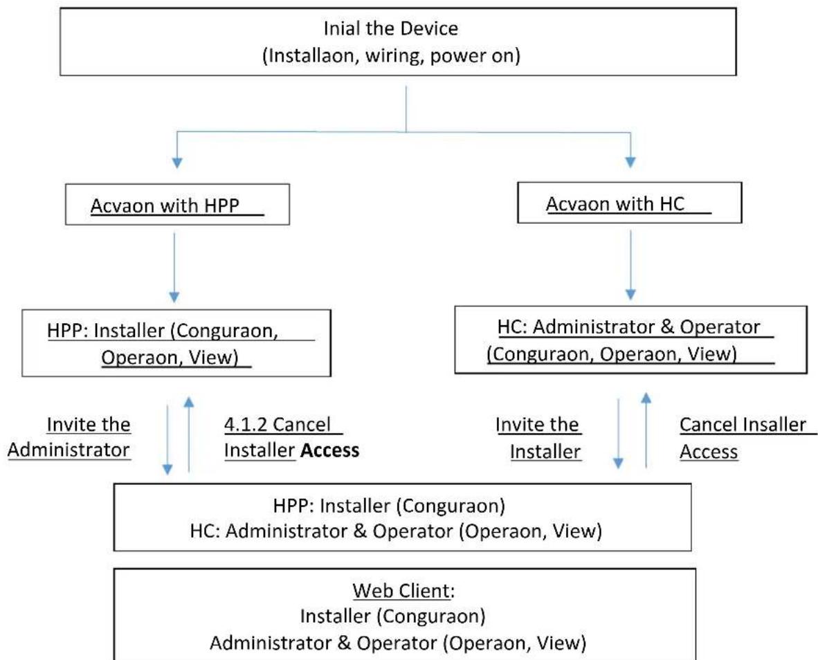
flowchart
graph TD
    A["Initial the Device (Installaon, wiring, power on)"] --> B["Acvaon with HPP"]
    A --> C["Acvaon with HC"]
    B --> D["HPP: Installer (Conguraon, Operaon, View)"]
    C --> E["HC: Administrator & Operator (Conguraon, Operaon, View)"]
    D --> F["Invite the Administrator"]
    E --> G["Invite the Installer"]
    F --> H["HPP: Installer (Conguraon) HC: Administrator & Operator (Operaon, View)"]
    G --> I["Web Client: Installer (Conguraon) Administrator & Operator (Operaon, View)"]
    H --> J["4.1.2 Cancel Installer Access"]
    I --> K["Cancel Installer Access"]
For more informaon, refers to Chapter 4 User Management.
3.2 Acvaon
While initial the device with Hik-Partner Pro or Hik-Connect, the AX PRO should always be added to an installer account rst. The installer account will invite and transfer ownership to the administrator account later aer nishing all initial setup and test. Follow the steps below to inializing the wireless alarm system.
You can acvate the device by Wi-Fi, LAN or SIM(4G/GPRS).
3.2.1 Acvaon with LAN/SIM(4G/GPRS)
Step1 Create a site (Only for HPP)
Download the Hik-Partner Pro and login with the installer account.
A site is the place where the alarm system deployed. Create a site where the device can be added to with it's site name and address. The owner of the site would be an end user, usually regarded as administrator.
Step2 Connect to the network.
Connect the device to the Ethernet with LAN or SIM, and power the device on.
iNote
- While the device is powered on, the power LED turn green.
- Once the device connected to the network, the 📋 LED indicator turns green.
- Make sure the SIM card you insert can connect to the network.
Step3 Add Device
- Open the site. (Only for HPP)
iNote
While initial the device with Hik-Connect, you do not need to build a site rst.
- Tap + and scan the QR code on the label of the panel.
- Tap Add.
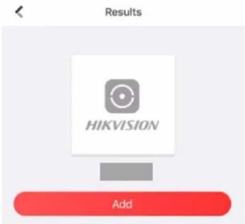
Figure 3-1. Add Device
- Tap Next. You can edit parameters of the device or skip to use it directly.


Figure 3-2. Adding Completed
The control panel will be added to the site (HPP) created and managed by the installer account, which also means that the installer account was created in the panel.
The installer now can perform conguraon and tests of the panel before deploying. Both Hik-Partner Pro/Hik-Connect Service and local web client can be logged in with the Hik-Partner Pro/Hik-Connect installer account.
iNote
While initial the device with Hik-connect, you do not need to build a site rst. Download and login the App, and add the device by scanning QR code or enter the device serial No.
3.2.2 Acvaon with Wi-Fi
Step1 Create a site (Only for HPP)
Download the Hik-Partner Pro and login with the installer account.
A site is the place where the alarm system deployed. Create a site where the device can be added to with it's site name and address. The owner of the site would be an end user, usually regarded as administrator.
Step2 Congure the Network on APP
- Download Hik-Connect/Hik-Partner Pro and log in.
- Power on the AX PRO.
-
Open the HC or HPP, click +, and select Scan QR Code.
-
Connect your phone to your home Wi-Fi. Make sure that this Wi-Fi can access the Internet normally and the signal is stable.
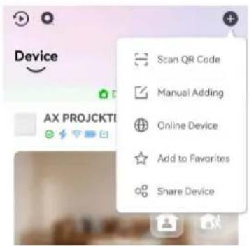
Figure 3-3. Scan QR Code
- Scan the QR code on the back of the control panel and wait for the result.

Figure 3-4. QR Code
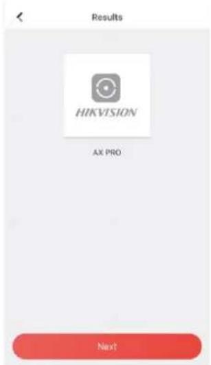
Figure 3-5. Result
- Tap Next.
7. Tap Wireless Connecon.
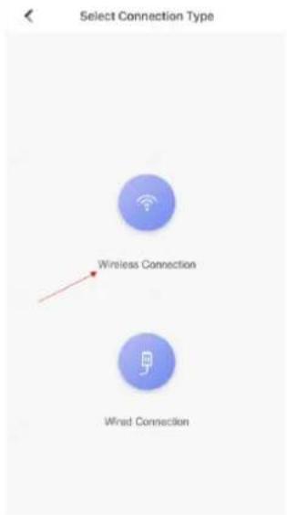
Figure 3-6. Connecon Type
8. Check The device is started. And then tap Next.
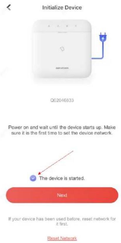
Figure 3-7. Device Is Started
- The APP will automacally ll in the home Wi-Fi currently used by the mobile phone into the page, as shown in the gure below. Aer conming the Wi-Fi password, tap Next.
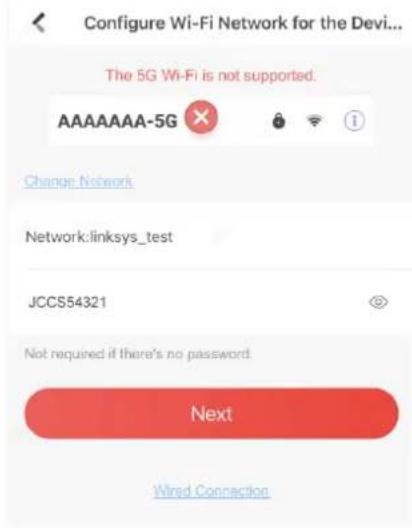
Figure 3-8. Congure Wi-Fi
10. Tap Connect to a Network.
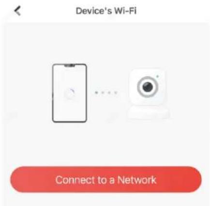
Figure 3-9. Connect to Network
- Tap Join. The mobile phone will disconnect the home Wi-Fi. Aer interacng informaon with the control panel, the mobile phone will automatically switch back to the home Wi-Fi.
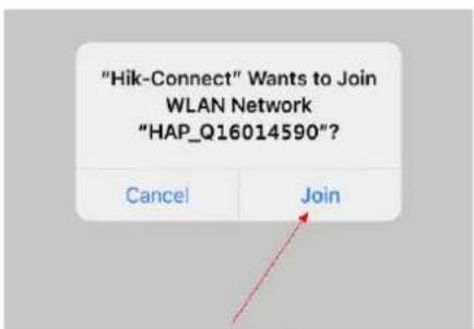
Figure 3-10. Join Wi-Fi
As shown in the gure above, during the informaon interacng, the Wi-Fi connected to the mobile phone named "HAP_serial number" (AX PRO serial number)
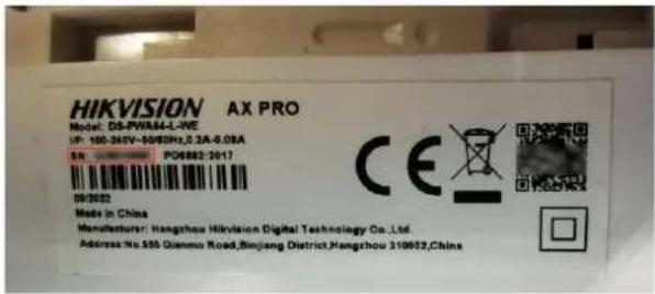
Figure 3-11. Serial Number
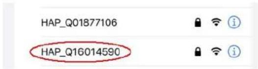
Figure 3-12. Wi-Fi
- Aer the control panel broadcasts the "Exit hotspot mode", the following page will appear.
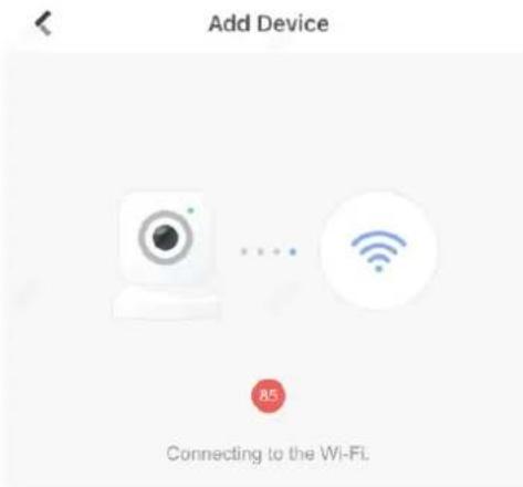
Figure 3-13. Connecng to Wi-Fi
- Wait for the device to join the home Wi-Fi and log in the EZVIZ Cloud.
(1) When the home Wi-Fi signal is good, the control panel will successfully log in to EZVIZ Cloud and complete the binding before the countdown ends.
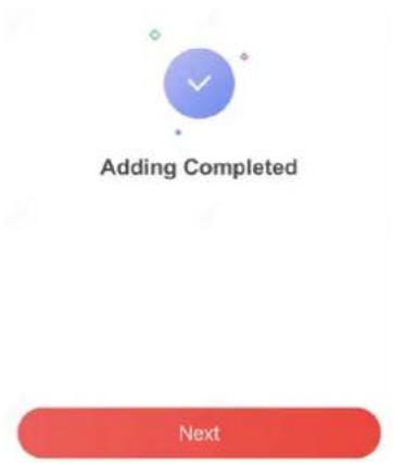
Figure 3-14. Adding Completed
(2) When the home Wi-Fi signal is unstable, the control panel may not be connected to the EZVIZ Cloud before the countdown ends, and the following page will appear:
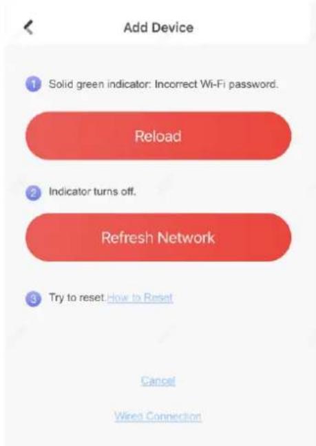
Figure 3-15. Reload
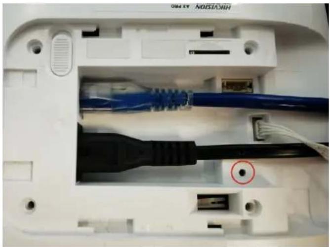
If you make sure that the home Wi-Fi password is correct and quality is good, tap Refresh Network, the control panel will enter a new countdown. You can wait for the conncon. If you want to change the home Wi-Fi, you should change the home Wi-Fi connected to the mobile phone rst, then press the RESET buon on the back of the control panel (marked in the gure below). Aer hearing the voice of "Enter hotspot mode", tap Reload. The interface will jump back step 9, you can congrure the network again.
natural_image
Close-up of a white electronic device showing internal components including USB cable, connectors, and a red circle highlighting a specific cable (no text or symbols visible)Figure 3-16. Reset Buon
iNote
Once the device connected to the network, the LED indicator turns green.
3.3 Unbind the Device
3.3.1 Unbind the Device from Your Own Account
When the device is bound to your own account, you can delete it directly.
-
On the device list page, tap the AX PRO and then log in to the device (if required) to enter the page.
-
Tap

- Tap Delete Device.
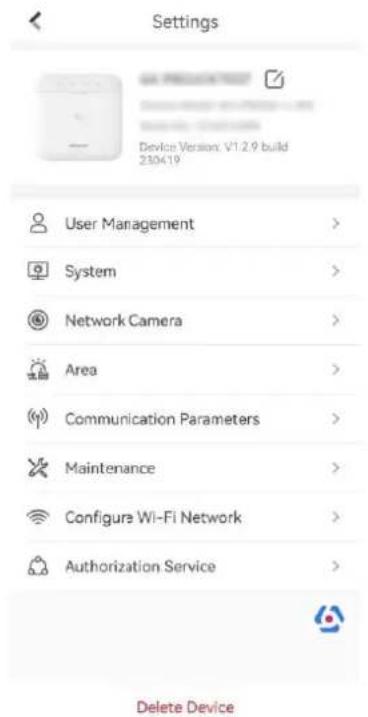
Figure 3-17. Sengs
3.3.2 Unbind the Device from Another Account
Make sure the control panel is in your hands.
The phone and device are on the same network segment.
- Open HC and tap +.
- Tap Scan QR Code.
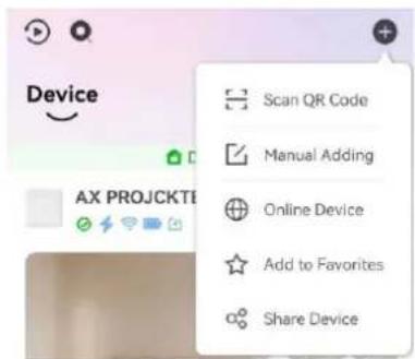
Figure 3-18. Scan QR Code
- Scan the QR code on the label of the device.

Figure 3-19. QR Code
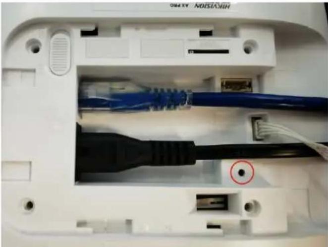
- Press the RESET buon twice quickly on the back of the device.
natural_image
Close-up of a white electronic device showing internal components including USB cable, connectors, and a black connector (no text or symbols visible)Figure 3-20. Reset Buon
- Tap Unbind Device.
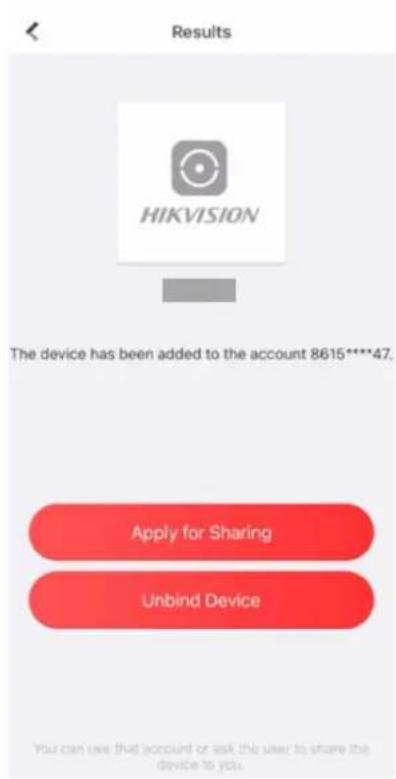
Figure 3-21. Unbind Device
- Enter vericaon code and tap Finish.
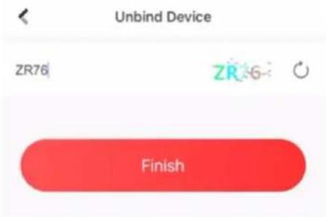
Figure 3-22. Vericaon Code
The device is unbound from the account. You can add it to your account now.
iNote
The maximum duraon of unbinding mode is 3 minutes. Aer the meout, the device will automacally exit the unbundling mode.
Chapter 4 User Management
4.1 User Management
iNote
- The users can be created in clients.
- The name and password of network user (web client and APP user) can be 1 to 32 characters and 8 to 16 characters.
4.1.1 Invite the Administrator
Aer the initial conguraon nished, the service provider in Hik-Partner Pro can transfer the device to the administrator on the Hik-Connect.
Before You Start
Make sure the site status is Not Handed Over, and you have the permission for site management, such as managing all sites and assigning sites.
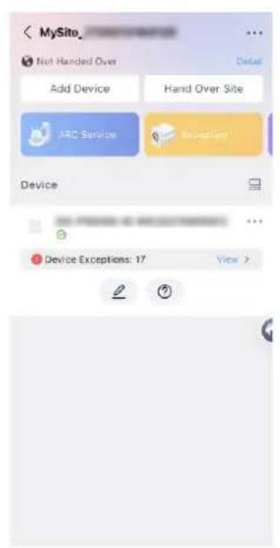
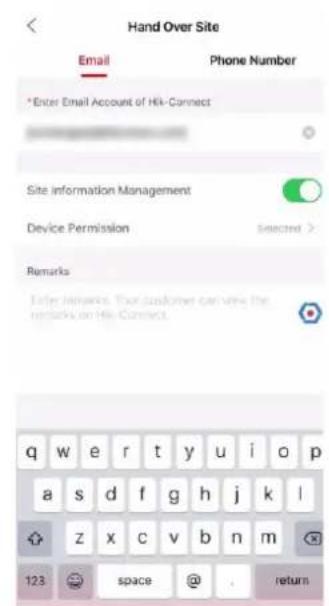
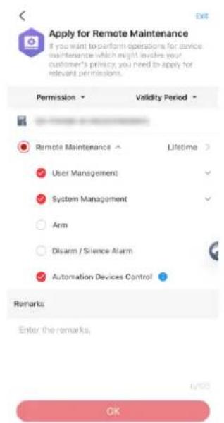
Figure 4-1. Hand Over
- In the site, tap Hand Over Site → Hand Over by Sharing.
- Tap Transfer.
- Enter the recipient's email address or phone number.
-
Tap Device Permission. You can select the conguraon permissions that the recipient gets and the valid me.
-
Tap OK.
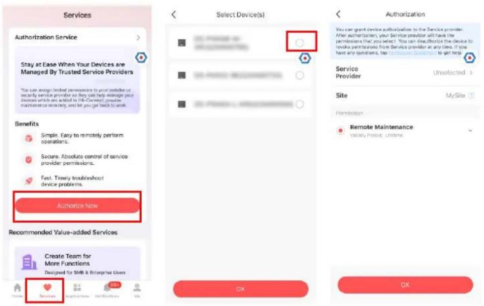
- Open the Hik-Connect APP and login with the administrator account. The installer service request will be pop-up or received at nocaon page.
- Tap Service → Authorize Now select a control panel.
- Select a control panel and tap OK.
- Set service provider and permission.
- Tap OK. The device will be display in your device list.
The administrator account will be added to the control panel, which could be used to login to Hik-Connect app and local web client.
4.1.2 Cancel Installer Access
The administrator can cancel the access authorizaon of the service provider.
- Enter the Service page.
- Tap the service provider.
- Tap ... → Cancel Authorizaon.
- Conrm the operaon, and the authorizaon of the installer will be canceled. Once the authorizaon is canceled, the installer need to apply it again if any access requirement.
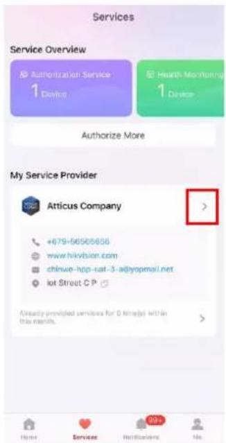
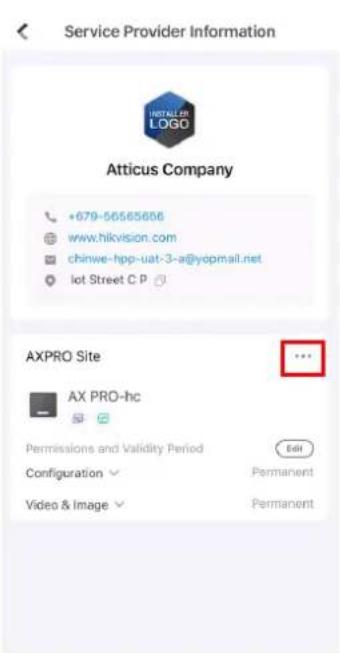
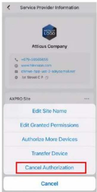
Figure 4-2. Cancel Authorizaon
4.1.3 Add an Operator
The administrator can share the device to other operators.
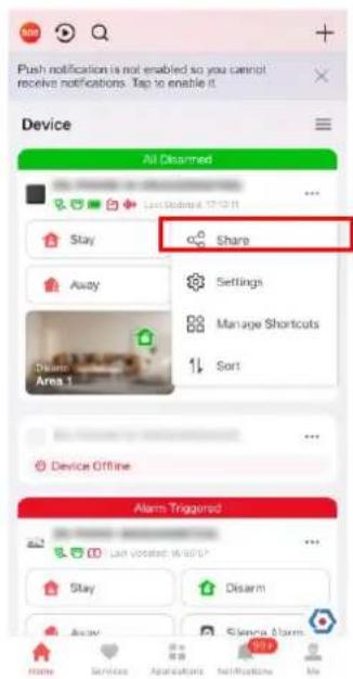
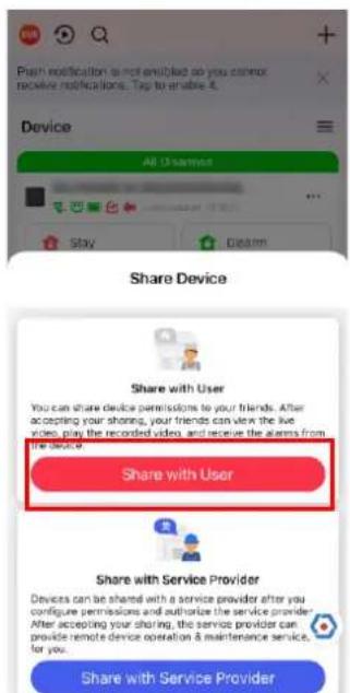
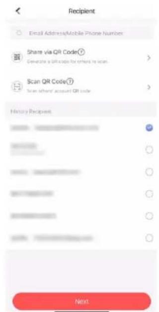
Figure 4-3. Share with User
- Tap ... → Share → Share with User.
- Enter an operator account or select a history recipient. Administrator can also select which device to be share
- A sharing message will be sent to the operator's account, and the operator can read the message in the nocaon page of Hik-Connect App.
The operator account will be added to the control panel, which could be used to login to Hik-Connect app and local web client.
4.1.4 Invite the Installer
The service provider on the Hik-Partner Pro APP is invited to control the device.
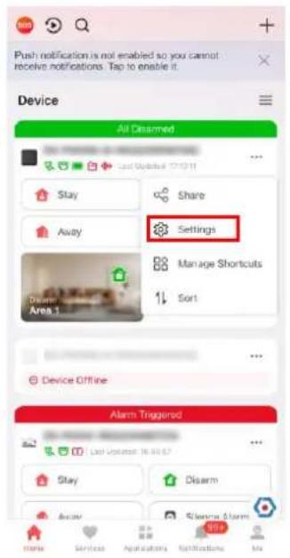
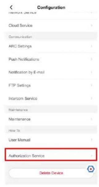
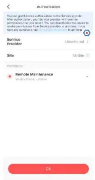
Figure 4-4. Invite the Installer
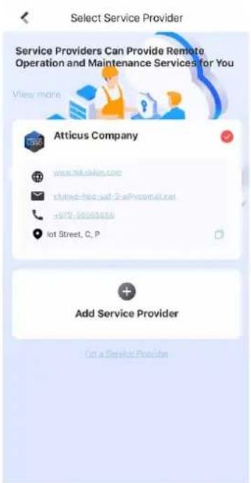
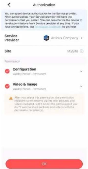
Figure 4-5. Invite the Installer2
-
Login Hik-Connect, tap ... → Sengs
-
Tap Authorizaon Service.
- Tap Service Provider.
- Select a service provider or add a new one.
- Tap OK in authorizaon page.
- Select conguraon permission you want to send and tap OK.
4.2 Access Entries
The installer and operators of the AXPRO were assigned dierent access levels which denote the system funcons that an individual user can perform. Various user entries are provided for dierent user roles with particular access level.
Access entries for Installers (Access Level 3)
● Hik-Partner Pro Service
Hik-Partner Pro is a service for installers that is used to manage customers' alarm systems located in various sites remotely. Control panels can be added to an installer account on the Hik-Partner Pro Service and be managed in sites.
- Local Web Client
Visit the device IP address that can be found out with SADP tool. The installer can login with Hik-Partner Pro service account aer the panel was added.
- Other Entries
Keypad PINs and tags can be also assigned with installer user at parcular access level to perform essenal operaons.
Access Entries for the Administrator and Operators (Access Level 2)
● Hik-Connect Service
The Hik-Connect service can be used for end users to access and manage the devices.
- Local Web Client (for the administrator)
As soon as the panel was added to the end user account on Hik-Connect Service, the Hik-Connect account can be used to login to the web client build in.
Operators cannot login the web client.
- Other Entries
Keypad PINs and tags can be also assigned with end user at parcular access level to perform essenal operaons.
Chapter 5 Conguraon
5.1 Set-up with Hik-Partner Pro
5.1.1 Use the Hik-Partner Pro APP
The installer can use the Hik-Partner Pro to conjure the AX PRO, such as acvaon, device enrollment, etc.
Download and Login the Hik-Partner Pro
Download the Hik-Partner Pro mobile client and login the client before operang the AX PRO.
Steps
- Download Hik-Partner Pro mobile client.
- Oponal: Register a new account if it is the rst me you use the Hik-Partner Pro mobile client.
iNote
- For details, see User Manual of Hik-Partner Pro Mobile Client.
-
You need an invitaon code for registraon. Please ask technical supports.
-
Run and login the client.
Add AX PRO to the Mobile Client
Add AX PRO to the mobile client before other operaons.
Steps
- Power on the AX PRO.
-
Create or search a site.
-
Tap +, set site name, me zone, address, city, state/province/region and tap OK to create a site.
-
Enter site name in the search area and tap Search Icon to search a site.
-
Tap Add Device.
- Tap Scan QR Code to enter the Scan QR code page. Scan the QR code on the AX PRO.
iNote
Normally, the QR code is printed on the label stuck on the back cover of the AX PRO.
Tap Manual Adding to enter the Add Device page. Enter the device serial No. and vericaon code to add the device.
- Acvate the Device.
Add Peripheral to the AX PRO
Add peripheral to the AX PRO.
Steps
- Select a site.
- Select a control device (AX PRO).
- Tap the + icon.
- Scan the QR code on the peripheral.
- Tap 📋 to enter the Manually Input page. Enter the device serial No. and select the device type to add the device.
Main Page
You can view faults, arm and disarm areas, view device status, etc.
On the device list page, tap the AX PRO and then log in to the device (if required) to enter the page.
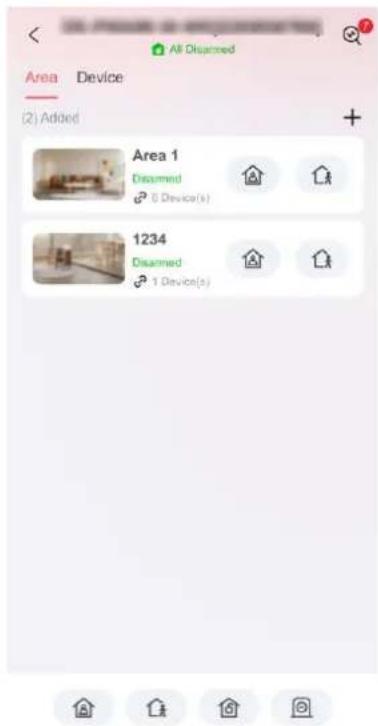
Figure 5-1. Main Page
View Faults
Tap to view faults.
Area Management
Tap + to add an area.
Tap Area to enter the area management page. Refers to Set Arming/Disarming Schedule for
details.
Arm/Disarm the Area
Arm or disarm the area manually as you desired.
On the device list page, tap the AX PRO and then log in to the device (if required) to enter the Area page.
Operations for a Single Area

Area 1
Disarmed
6 Device(s)


Figure 5-2. Single Area
- Away Arming: Tap 📁 to away arm a single area. When all the people in the detecon area leave, turn on the Away mode to arm all zones in the area aer the dened dwell me.
- Stay Arming: Tap 📁 to stay arm a single area. When all the people stays inside the detecon area, turn on the Stay mode to arm all the perimeter burglary detecon set in all the zones of all areas.
Operaons for Mulple Areas


Figure 5-3. Mulple Area Key
- Away Arming: Tap 📁 to away arm all areas. When all the people in the detecon area leave, turn on the Away mode to arm all zones in all areas aer the dened dwell me.
- Stay Arming: Tap 🔒 to stay arm all areas. When the people stays inside the detecon area, turn on the Stay mode to arm all the perimeter burglary detecon (such as perimeter detector, magnec contacts, curtain detector in the balcony) set in all the zones of all areas. At the meanme, the detectors inside the detecon area are bypassed (such as PIR detectors). People can move inside the area and alarm will not be triggered.
- Disarming: Tap 🔒 to disarm all areas. In Disarm mode, all the zones of all areas will not trigger alarm, no maer alarm events happen or not.
- Silent Alarm: Tap 📄 to silent alarms for all areas.
Device Management
- Tap Device to view linked devices.
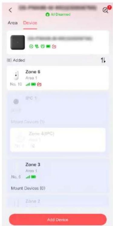
Figure 5-4. Device Page
- Tap Add Device to add a new device.
- Tap a device/zone to enter the management page. You can view device status (e.g. temperature, baery status, single strength, etc.).
- Tap 📍 on the upper right corner to enter the zone sengs page.
- Select a zone type.
You can view the congorable zone types for various detectors through I. Detector Zone Types.
Instant Zone
This Zone type will immediately trigger an alarm event when armed.
Delay Zone
-Exit Delay Time: Exit Delay provides you me to leave through the zone without alarm. You should conrm faults rst, and then the zone is in arming process. If the delay zone is triggered within the exit delay me but it restores before the me ends, the alarm will not be triggered and the zone will be armed.
-Entry Delay Time: Entry Delay provides you me to enter the zone to disarm the system without alarm.
Aer triggering, if the zone is not disarmed or silenced before the entry delay me ends, the zone will alarm.
-Stay Arm Delay Time: Stay arming uses Stay Arm Delay Time to count down.
The system gives Entry/Exit delay me when it is armed or reentered. It is usually used in entrance/exit route (e.g. front door/main entrance), which is a key route to arm/disarm via operang keypad for users.
Panic Zone
24-hour acve zone, whether armed or not. Report panic alarm aer triggering. It is usually used in the sites equipped with panic buon, smoke detector and glass-break detector.
Medical Alarm
24-hour acve zone, whether armed or not. Report medical alarm aer triggering.
Fire Zone
24-hour acve zone, whether armed or not. Report re alarm aer triggering.
Gas Zone
24-hour acve zone, whether armed or not. Report gas alarm aer triggering.
Follow Zone
The zone acts as delayed zone when it detects triggering event during system Entry Delay, while it acts as instant zone otherwise.
Keyswitch Zone
Trigger Type:
-By Trigger Time: Change the arming and disarming status aer each trigger. For example, in the disarmed status, if the zone is triggered, the linked area will be armed. Trigger the zone again and the area will be disarmed.
-By Zone Status: You need to choose to arm or disarm the linked area aer the zone is triggered.
In the case of the lid opened alarm, the arming and disarming operaon will not be triggered.
Disabled
Zone disabled ignoring any alarm event. It is usually used to disable faulty detectors.
24-hour Zone
The zone acvates all the me with sound/light output when alarm occurs, whether it is armed or not. It is usually used in re-hazardous areas equipped with smoke detectors and temperature sensors.
Timeout Zone
The zone acvates all the me. When this zone has been triggered or restored and exceeds the set me, an alarm will be generated.
It can be used in places equipped with magnec contacts that require access but for only a short period (e.g., re hydrant box's door or another external security box door).
-Not-Triggered Zone Alarm: If the zone is not triggered for the set me, it will alarm.
-Alarm on Zone Acvated: If the zone is triggered for the set me, it will alarm.
-Retry Time Period: Set the meout period.
- Enable other parameters according to your actual needs.

Note
The supported funcons vary depending on the zone types. Refer to the actual zone to set the funcon.
Arm Mode
If the zone is a public zone (the zone is belongs to more than one areas), you can set arm mode.
And: When all linked areas are armed, the zone will arm. When any of linked areas is disarmed, the zone will disarm.
Or: When any of the linked areas is armed, the zone will arm. When all linked areas are disarmed, the zone will disarm. When the zone is in alarm, the disarmed areas linked with the zone cannot be armed.
Stay Arm Deacvaon
The zone will be automacally bypassed in stay arming.
Chime Zone Enabled
Enable the doorbell. Usually used for door magnec detectors.
Alarm Input 1/Alarm Input 2
Enable the funcon and the set the detector's contact type.
Shock Detecon
Enable the funcon and you can set the shock sensitivity. The higher the number, the more easier to trigger an alarm.
PIR Sensitivity
If the zone is linked with an PIR camera, you can set the PIR sensitivity. The higher the sensitivity, the more easier to trigger an alarm.
Forbid Bypass on Arming
Aer enabled, you cannot bypass zones when arming.
Image Resoluon
Set the captured image resoluon.
Image In Series
Set the captured image number.
Trigger Interval
Set the trigger interval. If a target trigger the zone, an alarm will be triggered and sent every congured me interval until the target geng out of the zone.
Tilt Detecon
Enable the funcon an you can set the lt angle according to actual senarios.
Silent Alarm
Aer enabled, when an alarm is triggered, only the report will be uploaded and no sound is emied.
Double knock
Aer enabled, the me interval can be set. If the same detector is triggered twice or connuously in a period of me, the alarm will be triggered.
Cross Zone
PD6662 is not enabled: You need to set the combined me interval.
When the rst zone is triggered, the system will start ming aer the zone is restored. If the second zone is triggered within the set me, both zones will give alarms. Otherwise, no alarm will be triggered.
If the rst zone is not be restored, both zones will give alarms when the second zone is triggered, regardless of whether the set me has elapsed.
PD6662 is enabled: You need to set the combined me interval.
The rst zone will give an alarm when triggered. If the rst zone is not restored and the second zone is triggered, the system will report the alarm conrmaon.
If the rst zone is restored, the system will start ming. If the second zone is triggered within the set me, the system will report the alarm conrmaon.
If the rst zone is restored, the system will start ming. If the second zone is not triggered within the set me, no informaon will be reported.
Link PIR Camera
You can link some zone to a PIR camera. Check a zone that has a PIR camera.
Sounder Delay Time
The sounder will be triggered immediately (0s) or aer the set me.
LED
You can select to enable/disable the LED funcon.
Acvaon Limit (Time(s))
Set the trigger mes. When the trigger me exceeds the congured mes, it will not upload an alarm.
Polling Rate
Sets the interval at which the system requires the device to return a report. If the device takes longer than the Polling failure Times to determine oine to reply, the system will report faults and the status of device will be shown as oine.
Final Door Exit
Only magnec contacts have this opon.
Aer enabling, when the user use keypads or tag readers to arm:
-Arm With Faults is enabled: During the arming countdown, if the magnec contact is triggered and then restored, the arming process will be terminated immediately aer restoring, and the arming is completed.
-Arm With Faults is disabled: If the magnec contact is triggered and then restored, the linked area immediately arms the delayed zone.
AM Mode
-Alarm Only When ARM: An-masking alarm will be triggered only when the zone is armed.
-Alarm Only When ARM or DISARM: An-masking alarm will be triggered whether the zone is armed or disarmed.
Warning Time Enable
Set the warning me. The warning me countdown will be triggered if the instant zone is triggered during entry delay or the system not be disarmed aer entry delay ends. Local alarms are generated during the period, but no messages will be pushed.
Swinger Limit Acvaons
When the number of mes the infrared detector is triggered exceeds the set value, the alarm will no longer be triggered. (Except for an-masking alarms.).
Dual Zone (Wired Zone)
Aer enabled, when mul transmier detects that the enre zone circuit of the local zone and the extended zone is open circuit, both zones trigger lid opened alarms.
Permanent Deacvaon
-O: The deacvaon funcon is not enabled.
-Lid Only: Only tamper funcon is deactivated, and will not display lid open in the system.
-Enrely: The device is permanently deactivated and will not nofy about alarms or faults for one arming cycle.
One-Time Deacvaon
-O: The deacvaon funcon is not enabled.
-Lid Only: Only tamper funcon is deactivated, and will not display lid open in the system.
-Enrely: The device is permanently deactivated and will not nofy about alarms or faults.
Signal Strength Test
Test the detector's signal strength. If the signal is weak, you should change the detector's position to get a strong signal.
Detecon Zone Test
Simulate intrusions into the room from its doors, windows or other possible entrances to check if alarms can be triggered. The indicator will turn blue when an alarm is triggered.
Find Me
Click Find Me and the detector's indicator will ash or it will makes a sound.
User Guide
View the detector's user manual.
- If required, link a PIRCAM or a camera for the zone.
- Click OK.
User Management
The administrator and the installers can manage users. If you are the administrator, you can add,
edit, and delete users, and assign dierent permissions to the newly-added users.
Steps
iNote
There are three types of users for the AX PRO, including administrator (or owner), operator, and installer (or seer). Dierent types of users have dierent permissions for accessing the funconality of the AX PRO.
- On the device list page, tap the AX PRO and then log in to the device (if required) to enter the AX PRO page.
- Tap Device and tap the AX PRO.
- Tap → User Management to enter the sengs page.
- Tap Add and set the basic informaon.
User Property -Lifeme: Permanent use. Congurable with full user permission.
-One-Time User: Expired aer arming or disarming once, or automacally expires aer 24 hours. No duress code permission. No keyfobs and tags permission.
-Valid Time Period: Set the length of use for this user through me conguraon, congorable with full user permissions.
Phone Number Enter the phone number for the user. The mobile phone number should be with internaonal area code.
Keypad Set the keypad's operaon passcode and duress passcode. The user can use the passcode to control the keypad.
Permission Set the permissions for the user.
iNote
Only the administrator can do such an operaon.
You can link area for the user to arm, disarm/silence alarm.
Automaon Device Control: If enable the funcon, the user can control the relay open/closed.
Linked Area If the target user is an operator, tap the target user on the user list and then tap to set the area linked to the target user.
iNote
Only the administrator can do such an operaon.
Change Keypad Password If the target user is an administrator, an installer or an operator, you can tap the target user on the user list and then tap Change Keypad Password to set the keypad password to the target user.
| iNoteThe password (PIN code) is allowed to be 4 to 6 digits. No number is disallowed, with 10,000 to 100,000 diers, and no limit of the digit combinaon.Aer you add one keypad, you can add PIN code (Keypad Password) in the user menu. When you click in the input box, there will be indicaon shows that 4 to 6 numbers allowed. This is the same for each user | |
| Change Duress Password | If the target user is an administrator or an operator, you can tap the target user on the user list and then tap Change Duress Password to set the duress password to the target user. |
| iNoteIf under duress, you can enter the duress code on the keypad to arm and disarm area(s) and upload a duress alarm. | |
| Card/Tag/Keyfob | An administrator, an installer or an operator can use cards/tags or keyfob. |
iNote
- Conguraon items and user permission will vary according to the user type.
-
You can view linked Card/Tag and Wireless Keyfob of the user.
-
Tap Next and set the message/phone call push parameters.
- Slide the block to enable/disable the event. When the device event is triggered, a message or phone call will be sent to the reserved phone number.
Card/Tag Management
Aer adding cards/tags to the wireless AX PRO, you can swipe the card/tag to arm or disarm all the detectors added to specific area(s) of the AX PRO, and silence alarms.
iNote
The tag ID/PIN is a 32 bit long integer, and the variant could be 42949672956.
Steps
- In the site, tap the AX PRO and then log in to the device (if required) to enter the page.
-
Tap Device and tap the AX PRO.
-
Tap 📍 → User Management to enter the sengs page.
- Tap a user to enter the conguraon page.
- Tap tag/keyfob.
- Tap Add.
-For Keyfob: scan the QR code of the keyfob to add.
-For Tag: When hearing the voice prompt "Swipe Tag", you should present the tag on the AX PRO tag presenng area.
When hearing a beep sound, the tag is recognized.
The tag will be displayed on the tag list.
- Oponal: Tap a keyfob/tag to enter the conguraon page and you can set the keyfob/tag parameters.
iNote
- If you log in as an installer, skip this step. Eding tag name is only available to administrator.
-
The name should contain 1 to 32 characters.
-
Select the tag type.
- Oponal: Tap Delete Device to delete the keyfob/tag.
Device Informaon
You can change language and select me zone.
Steps
- In the site, tap the AX PRO and then log in to the device (if required) to enter the page.
- Tap Device and tap the AX PRO.
- Tap ➕ System Sengs to enter the sengs page.
- You can view device basic informaon, select device language, me, and set control panel opons.
Panel LED
Enable/Disable panel functional LED.
Arm LED/Cloud LED
Enable arm/cloud LED indicator.
Fault LED Stays On When Armed
Aer arming, the fault indicator remains on.
Voice Prompt
If the opon is enabled, the AX PRO will enable the voice prompt.
Panel Volume
The available system volume range is from 0 to 10.
Fault Prompts When Arming
Voice prompt of faults when the system is armed.
Enable/Disable sound prompt. Set the panel volume and sound prompt opons.
Alarm Prompts
Voice prompt of faults when an alarm is triggered.
Fault Prompts When Armed
The system will make voice prompts when the control panel is armed.
Fault Prompts When Arming
The system will make voice prompts when arming.
Fault Prompts When Disarmed
The system will make voice prompts when the control panel is disarmed.
Fault Prompts When Disarming
The system will make voice prompts when disarming.
Tamper Alarm
When a tamper alarm is triggered, a voice prompt will be triggered.
System Alarm Duraon
Set linked alarm voice prompt lasng me.
Service Sengs
Congure the fault check, arming and regional cercaon.
Steps
- In the site, tap the AX PRO and then log in to the device (if required) to enter the page.
- Tap Device and tap the AX PRO.
- Tap → Service to enter the sengs page.
- You can set the service parameters.
Re-Arm on Restore
While enabled, aer the detector is bypassed, if its faults are restored and the linked area is armed, the detector will automatically arm.
Audible Tamper Alarm
While enabled, the system will alert with buzzer for the tamper alarm. Regardless of whether it is enabled or not, the tamper alarm will be normally pushed to Cloud (for APP) and ARC.
Jamming Sensivity Sengs
The device will detect RF interference and push messages when the RF interference interferes with communicaon. You can adjust the detecon sensitivity.
Moon detectors include all PIR detectors.
-O: No automac restore.
-Immediate Aer Alarm: Moon detectors automacally restores immediately aer the alarm and reports to Cloud (for APP) and ARC.
-Aer Disarm: Moon detectors automacally restores aer disarming and reports to Cloud (for APP) and ARC
Fault Checklist when Arming
The system will check if the device has the faults in the checklist during the arming process. The fault check here is only for the control panel in the normal status.
The system determines whether to check the faults listed on the page. The system will only check the fault that is selected.
Baery Status
Baery Lost
If the opon is enabled, when baery is disconnected, the device will upload events.
Low Baery
If the opon is enabled, when baery is in low baery status, the device will upload events.
Zone/Peripherals Low Baery
If the opon is enabled, when zone or peripherals' baery is in low baery status, the device will upload events.
Power Supply Availability
Panel Mains Power Lost
If the opon is enabled, an alarm will be triggered when the control panel main supply is disconnected.
To compliant the EN 50131-3, the report dealy duraon should be 10 s.
Peripheral Mains Power Lost
If the opon is enabled, when the peripheral's main power is lost, the alarm will be triggered.
Device Connecon
Zone/Peripherals Poll Failure/Oine
If the opon is enabled, when zone or peripherals' conncon is lost, the alarm will be triggered.
IP Camera Disconnecon
If the opon is enabled, when the network camera's conncon is lost, the alarm will be triggered.
Server Connecon
Ethernet Lost
If the opon is enabled, when the wired network is disconnected or with other faults, the alarm will be triggered.
Wi-Fi Lost
If the opon is enabled, when the Wi-Fi is disconnected or with other faults, the alarm will be triggered.
Cellular Lost
If the opon is enabled, when the cellular data network is disconnected or with other
faults, the alarm will be triggered.
Lid Status
If the opon is enabled, an alarm will be triggered when the control panel is lid open.
ARC Connecon
If the opon is enabled, an alarm will be triggered when the ARC (Alarm Receiving Center) conncon contains fault.
Jamming Detecon
If the opon is enabled, an alarm will be triggered when the control panel detectng jamming.
Zone Triggered Fault
If the opon is enabled, an alarm will be triggered when the control panel's zone triggering contains fault.
Panel-Server Polling Interval
Set the me interval when the control panel's server is polling.
Delay of Server Connecon Failure
If the control panel server cannot connected for the delayed me duraon, conneccon will failed.
Panel Fault Check
If the opon is enabled, an event will be reported aer the delayed me.
Power Saving Mode
While enabled, the main power supply is o, Wi-Fi enters low power consumption, 4G closes, tag reading fails. LED is o, and voice prompt is o.
PD6662
PD6662 is applicable to the UK market. If this funcon is enabled, the arming funcon and alarm logic of the control panel will change.
Enable PD6662 standard. Funcons that do not meet the standard will not take eect.
Communicaon Fault Sending Delay
The delay me while the ATP communicaon fault reports to ARC.
Panel Lockup Buon
All funcons of AX PRO will be frozen aer it is enabled. This funcon can only be enabled by users with installer permission.
Network Camera
Add Cameras to the AX PRO
Steps
-
In the site, tap the AX PRO and then log in to the device (if required).
-
Tap Device → Add Device → SADP Scan and Add Network Camera to enter the page.
SADP Scanning
Scan all network cameras in the same LAN. A list will pop up aer scanning. You can directly check to add cameras in the list.
Manually Add
If SADP scanning cannot nd a camera, you can tap Manually Add and enter IP address, port, the user name and password of the camera. Tap Conrm.
Set Video Parameters
Steps
- In the site, tap the AX PRO and then log in to the device (if required).
- Tap a camera and tap to enter the page.
- Set the video parameters.
Stream Type
Main Stream: Being used in recording and HD preview, it has a high resolution, code rate and picture quality.
Sub-Stream: It is used to transmit network and preview pictures as a video streaming with features of lower resolution, bit rate and picture quality.
Bitrate Type
Select the Bitrate type as constant or variable.
Resoluon
Select the resolution of the video output.
Bitrate
The higher value corresponds to the higher video quality, but the beer bandwidth is required.
Before Alarm
The recording me length before the alarm.
Aer Alarm
The recording me length aer the alarm.
Set Arming/Disarming Schedule
Steps
- In the site, tap the AX PRO and then log in to the device (if required) to enter the page.
- Tap Area to enter the page.
- Tap an area in the list, and tap Sengs.
- Set parameters:
Add to Home Shortcut
Enable the funcon and the area shortcut will be displayed on the home page.
Late to Disarm
Enable the funcon and set the me. If the alarm is triggered aer the congured me, the person will be considered as late.
Auto Arm
Enable the funcon and set the arming start me. The zone will be armed according to the congured me.
iNote
The auto arming me and the auto disarming me cannot be the same.
-Forced Auto Arm:
While the funcon is enabled, faults will be ignored when the system is automacally armed.
-Auto Arming Sound Prompt:
Aer enabled, the buzzer beeps slowly 2 minutes before the auto arming starts, and beeps rapidly 1 minute before the auto arming starts.
Aer disabled, the buzzer will not beep before auto arming.
Auto Disarm
Enable the funcon and set the disarming start me. The zone will be disarmed according to the congured me.
iNote
The auto arming me and the auto disarming me cannot be the same.
-Weekend Excepon:
Enable the funcon and the zone will not be armed in the weekend.
-Holiday Excepon:
Enable the funcon and the zone will not be armed/disarmed in the holiday. You should set the holiday schedule aer enabling. Up to 12 holiday groups can be set.
Communicaon
Wired Network
Steps
- In the site, tap the AX PRO and then log in to the device (if required) to enter the page.
- Tap Device and tap the AX PRO.
- Tap → Network Sengs → Ethernet to enter the sengs page.
- Set the parameters.
– Automac Sengs: Enable DHCP and set the HTTP port.
- Manual Setngs: Disabled DHCP and set IP Address, Subnet Mask, Gateway Address, DNS Server Address.
- Oponal: Set correct DNS server address if the device needs to visit Hik-Connect server via a domain name.
- Tap Save.
Wi-Fi Conguraon
Steps
- In the site, tap the AX PRO and then log in to the device (if required) to enter the page.
- Tap Device and tap the AX PRO.
- Tap → Network Sengs → Wi-Fi to enter the sengs page.
- Tap a Wi-Fi to connect in the list.
Cellular Sengs
Steps
- In the site, tap the AX PRO and then log in to the device (if required) to enter the page.
- Tap Device and tap the AX PRO.
- Tap → Network Sengs → Cellular to enter the sengs page.
- Select a SIM card and enable Cellular.
- Set parameters including the access number, user name, access password, APN, MTU, PIN, and IMSI.
Access Number
Input the operator dialing number.
iNote
Only the private network SIM card user needs to enter the access number.
User Name
Ask the network carrier and input the user name.
Password
Ask the network carrier and input the password.
APN
Ask the network carrier to get the APN informaon and input the APN informaon.
- You can also enable data limit funcon and set the trac.
- Edit Used Trac This Month and Trac Threshold.
Used Trac This Month
The used data will be accumulated and displayed in this text box.
Trac Threshold
You can enable the funcon and set the data threshold every month. If data usage is more than the congured threshold, an alarm will be triggered and uploaded to the alarm center and mobile client.
-
Tap Network Test to test the network.
-
Tap Save.
Network Service Sengs
- In the site, tap the AX PRO and then log in to the device (if required) to enter the page.
- Tap Device and tap the AX PRO.
- Tap 📋 → Network Service to enter the sengs page.
- Set the HTTP Port and tap Save.
Cloud Service Sengs
Steps
- In the site, tap the AX PRO and then log in to the device (if required) to enter the page.
- Tap Device and tap the AX PRO.
- Tap 📋 → Cloud Service to enter the sengs page.
- Select the Communicaon Mode.
Ethernet
The system will select wired network.
Wi-Fi
The system will select Wi-Fi.
Cellular
The system will select cellular data network.
- Enable Periodic Test. Enter the periodic test interval.
- Tap Save.
Alarm Receiving Center (ARC)
You can set the alarm receiving center's parameters and all alarms will be sent to the congured alarm center.
Steps
- In the site, tap the AX PRO and then log in to the device (if required) to enter the page.
- Tap Device and tap the AX PRO.
- Tap → ARC Sengs to enter the sengs page.
- Select an ARC and enable it.
Connecon Type
Set the conncon type as IP or Serial Port.
Protocol Type
Select the Protocol Type as ADM-CID, ISUP, SIA-DCS, *SIA-DCS, *ADM-CID, CSV-IP, FSK Module or RDC Module to set uploading mode.
Connecon Mode
Select the Transmission Mode as TCP or UDP. UDP is recommended by the SIA DC-09 standard.
Communicaon Channel
Ethernet
The system will select wired network.
Wi-Fi
The system will select Wi-Fi.
Cellular
The system will select cellular data network.
Server Address Type
Select the Address Type as IP Address and Domain Name. Enter server address/domain name, port number and account code.
Polling Opon
Set the polling rate with the range from 10 to 3888000 seconds. The system will report fault if the me is over the limit. The status of device will be shown as oine.
Periodic Test
Aer enabling, you can set the me interval, seng how oen to send a test event to the ARC to ensure the conncon.
Retry Timeout Period
Aer the selected me, the system will retry to transmit.
Aempts
Set the number of retry aempts.
Companies
Select the support company as None, Hungary-Mul Alarm Receiving Company or French Alarm Receiving Company.
PIRCAM Picture Upload Mode
When the control panel uploads the alarm informaon, it will return the picture and video address for you to view.
Push Nocaons
For details, see Push Nocaons.
GMT
Enable the Greenwich Mean Time.
ARC Push Nocaons
When an alarm is triggered, if you want to send the alarm nocaon to the mobile phone, you can set the nocaon push parameters.
Steps
- In the site, tap the AX PRO and then log in to the device (if required) to enter the page.
- Tap Device and tap the AX PRO.
-
Tap → ARC Sengs to enter the sengs page.
-
Select an ARC and enable it.
- Tap Push Nocaons and enable the funcon.
Alarm Event
Zone Alarm
The device will push nocaons when the zone alarm (on web client, soware client or mobile client) is triggered or the zone peripherals alarm is triggered or restored.
Panel Lid Opened
The device will push nocaons when lid opened alarm of the control panel is triggered or restored.
Peripherals Lid Opened
The device will push nocaons when lid opened alarm of any peripheral is triggered or restored.
Keypad/Keyfob/APP Panic Alarm
The device will push nocaons when panic alarm on keypads/keyfobs/APP is triggered or restored.
Keypad/Keyfob Medical Alarm
The device will push nocaons when medical alarm on keypads or keyfobs is triggered.
Keypad Fire Alarm
The device will push nocaons when re alarm on keypads is triggered or a user presses the re alarm key on the keypad.
Camera Events
The device will push nocaons when alarm is triggered in network cameras(using HIKVISION protocol).
PIRCAM Gif
The video and pictures generated by PIR cameras will be uploaded to the alarm receiving center.
Video Clips
The video and pictures generated by network cameras will be uploaded to the alarm receiving center.
Fault Event
Panel Status (Power and Baery)
The device will push nocaons when the control panel power/baery status is changed.
Panel Status (Communicaon)
The device will push nocaons when the control panel communicaon status is changed.
Zone Status
The device will push nocaons when any zone status is changed.
Peripherals Status
The device will push nocaons when any peripheral status is changed.
Operaon Event
System Operaon
The device will push nocaons when the user operate the control panel.
System Event
Panel Upgrade
The device will push nocaons when the control panel is upgraded.
- Tap APP and check events. The selected events will be pushed in the APP as important alarms.
ARC Disconnecon Report Delay
The device will push nocaons when Alarm Receiving Center is disconnected.
- Tap Phone Call and SMS.
- Tap + to enter the phone number.
- Tap the added phone number to enable Phone Call and SMS according to your need.
iNote
Do not congregate the phone number to the SIM card inserted in the device itself, otherwise abnormal charges will occur and the user will have to bear them.
(For Phone Call) Set number of calling when the phone is unanswered.
(For SMS) Set Arming Permission, Disarming Permission and Silence Alarm Permission for areas.
Common Message
You can enter message content. When the alarm is triggered, your customized content will be added at the beginning of the message sent by the system.
Common Voice
You can import a new audio. When the alarm is triggered, your customized voice will be added at the beginning of the content of the phone dialed by the system. You can also tap Clear to delete audios
iNote
Only WAV format is supported, up to 512 KB and 15 s.
- Check nocaons.
Nocaon by SMS
Steps
- In the site, tap the AX PRO and then log in to the device (if required) to enter the page.
- Tap Device and tap the AX PRO.
- Tap → Push Nocaons to enter the sengs page.
- Edit a message content and tap Save.
The message and alarm informaon will be sent to the user's reserved mobile phone number that has permissions.
Nocaon by Email
Steps
-
In the site, tap the AX PRO and then log in to the device (if required) to enter the page
-
Tap Device and tap the AX PRO.
-
Tap → Nocaon by E-mail to enter the sengs page.
-
Enable Email 1.
-
Enter the sender name, sender email address, SMTP server address, SMTP port, user name and password.
iNote
It is recommended to use Gmail and Hotmail for sending mails.
Only if the zone is linked with a network camera, the alarm email will be aached with alarm video.
-
Select the encrypon type as None, SSL or TLS.
-
Enable Server Authencaon. When the funcon is enabled, when the server ask an authencaon, the user name and password will be checked.
-
Enter receiver name and receiver email address. Tap Receiver Address Test to test whether the email address is correct.
-
Tap Save.
-
Oponal: Congure Email 2 in the same order. You can choose whether to set email 2 as a backup mailbox.
iNote
Video and picture reviews will be sent to both mailboxes. If Email 2 is set as a backup mailbox, the system will push emails to Email 2 only if Email 1 fails to receive.
FTP Sengs
Steps
-
In the site, tap the AX PRO and then log in to the device (if required) to enter the page.
-
Tap Device and tap the AX PRO.
-
Tap → FTP Sengs to enter the sengs page.
-
Select the FTP type as Main FTP or Standby FTP, and enable FTP.
-
Congure the FTP parameters
Protocol Type
FTP and SFTP are selectable. The les uploading is encrypted by using SFTP protocol.
Server Type
Select IP Address or Domain Name as the server address type.
Server Address / Domain Name / Port
The FTP server address and corresponding port.
Enable Anonymity
The FTP user should have the permission to upload pictures. If the FTP server supports picture uploading by anonymous users, you can enable anonymous to hide your device informaon during uploading.
Directory Structure
The saving path of snapshots in the FTP server.
- Tap Save.
Intercom Service
You can congregate the Intercom service for an intercom sounder.
Before You Start
You should enroll an intercom sounder rst.
Only one sounder can be set as the intercom sounder.
Steps
- In the site, tap the AX PRO and then log in to the device (if required) to enter the page.
- Tap Device and tap the AX PRO.
- Tap ➕ Intercom Service to enter the sengs page.
- Slide to enable the funcon.
- Set intercom type.
STD-SIP
The control panel will use ARC and standard SIP server.
IP Receiver Pro
The control panel supports intercom of cloud service and ISUP protocol.
ISUP
The control panel uses the ISUP protocol through the Hik-Central APP.
ESI-SIP
The control panel uses the ESI-SIP server.
- Select an intercom sounder and alarm verify priority and tap Save.
Device Maintenance
You can reboot the device.
Steps
-
In the site, tap the AX PRO and then log in to the device (if required) to enter the page.
-
Tap Device and tap the AX PRO.
-
Tap →Maintenance →Restart.
The AX PRO will reboot.
- Tap ⚙ → Maintenance → Reset.
You can reset the AX PRO partly or reset to default sengs.
- Oponal: Tap → Maintenance → Remote Log Collecon to enable the funcon.
Remote Log Collecon is for geng logs relang to the device. When this is enabled, our technical support will be able to collect logs relang to the device remotely and upload them to our server for troublesomeong. You can set the validity period according to actual needs. This funcon will be disabled aer the set validity period.
- Tap →Maintenance →Control Panel Upgrade to upgrade the control panel, or tap
→Maintenance → Detector & Peripheral Upgrade to upgrade detectors and peripherals.
- Tap →Maintenance →Walk Test to test the whether the device works properly or not.
Slide Enable. Trigger the detector in each zone.
iNote
Only when all the detectors are without fault, you can enter the mode TEST mode.
- Tap → Maintenance → Device Debugging.
Tamper Alarm on HPP Login
Aer this funcon is enabled, the device lid opened alarm (tamper alarm) takes eect when installer login. (By default, the lid opened alarm (tamper alarm) does not take eect when the installer login.)
Event Log for Cellular Service
If enabled, you can get the log when using the cellular service.
STA/AP Mode Switch
You can make the AX PRO connect to Wi-Fi through APP.
Steps
-
In the site, tap the AX PRO and then log in to the device (if required) to enter the page.
-
Tap Device and tap the AX PRO.
-
Tap → Network Sengs → Wi-Fi.
-
Follow the instrucons on the page and change the AX PRO to the AP mode. Tap Next.
-
Select a stable Wi-Fi for the device to connect.
-
Back to conguraon page to enter the Wi-Fi password and tap Next.
-
Tap Connect to a network and wait for conncon.
Aer the conncon is completed, the AX PRO will prompt to exit AP mode and automacally switch to STA mode.
5.1.2 Use the Hik-Partner Pro Portal
For AX PRO security control panel, you can perform operaons including arming/disarming area, silence alarm, bypassing zone etc., and remotely congregate the control panel on the Portal. You can
also apply for PIN (required for upgrading the rmware of AX PRO) and switch the language of AX PRO.
Click 📋 Site to enter the site list page, and then click the name of a site to enter site details page.
Remotely Operate AX PRO
Click the AX PRO to open the operaon panel. And you can perform the following operaons.
Table 4-3 Operaon Descripon
| Operaon | Descripon |
| Stay Arm a Specific Area | Select theArea tab, and then clickStay Armingto stay arm the area. |
| Away Arm a Specific Area | Select theArea tab and then clickAway Arming. |
| Disarm a Specific Area | Select theArea tab and then clickDisarm. |
| Stay Arm Mulple Areas | Select theArea tab, and then select areas and click. |
| Away Arm Mulple Areas | Select theArea tab, and then select areas and click. |
| Disarm Mulple Areas | Select theArea tab, and then select areas and click. |
| Silence Alarms of Mulple Areas | Select theArea tab, and then select areas and click. |
| Filter Peripheral Device by Area | Select theDevice tab, and then click and select an area to only display the peripheral devices linked to the selected area, or selectAllto display all the peripheral devices linked to all the areas. |
| Control Relay | Select theDevice tab, and then select a wireless output expander to display the sirens linked to it, and then select siren(s) to enable/disable them. |
| Bypass Zone | Select theDevice tab, and then select a zone (i.e., detector) and turn on theBypassswitch to bypass the zone. |
Remotely Congure AX PRO
You can click to enter the web page of the security control panel to congregate the device.

Note
For details about security control panel conguraon, see the user manual of the device.
Apply for a PIN
You can click → to open the Apply for a PIN window, and then PIN code will be displayed.
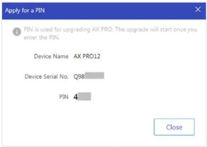
Figure 5-5. Apply for PIN
Switch Language

Note
You should have applied for a PIN.
You can click → to open the Language window, and then set the device language and
enter the PIN.
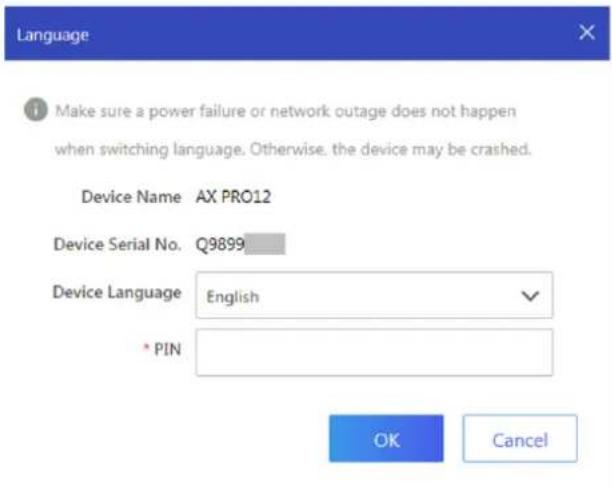
Figure 5-6. Switch Language
Health Monitoring
- Enter the Hik-Partner Pro Portal web site, and click Health Monitoring → Health Status to enter the page.
- Select a site.
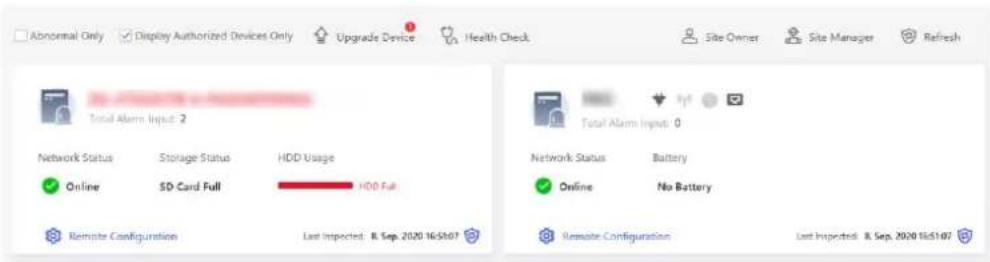
Figure 5-7. Health Monitoring
- Click Health Check, and click Check Now.
When checking is completed, you can view the status and reports of devices. You can also
export the report.
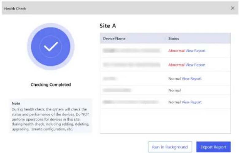
Figure 5-8. Checking Completed
- Click to get the latest device status.
5.2 Set-up with Hik-Connect
The operator can use the Hik-Connect to control the device, such as general arming/disarming operaon, and user management etc.
Download and Login the Mobile Client
Download the Hik-Connect mobile client and login the client before operang the AX PRO.
Steps
- Download Hik-Connect mobile client.
- Oponal: Register a new account if it is the rst me you use the Hik-Connect mobile client.

For details, see User Manual of Hik-Connect Mobile Client.
- Run and login the client.
Add AX PRO to the Mobile Client
Add an AX PRO to the mobile client before other operaons.
- Select adding type.
Tap + → Scan QR Code to enter Steps
- Power on the AX PRO.
the Scan QR code page. Scan the QR code on the AX PRO.

Normally, the QR code is printed on the label stuck on the back cover of the AX PRO.
Tap + → Manual Adding to enter the Add Device page. Enter the device serial No. with the Hik-Connect Domain adding type.
- Tap to search the device.
- Tap Add on the Results page.
- Enter the vericaon code and tap OK.
- Aer adding completed, enter the device alias and tap Save.
- Oponal: Tap → Delete Device to delete the device.
- Oponal: Tap → to edit the device name.
Add Peripheral to the AX PRO
Add peripheral to the AX PRO.
Steps
- Select a control device (AX PRO).
-
Tap + .
-
Tap Scan QR Code to enter the Scan QR code page. Scan the QR code on the peripheral.
- Tap 📁 to enter the Manually Input page. Enter the device serial No. and select the device type to add the device.
Main Page
You can view faults, arm and disarm areas, view device status, etc.
On the device list page, tap the AX PRO and then log in to the device (if required) to enter the page.
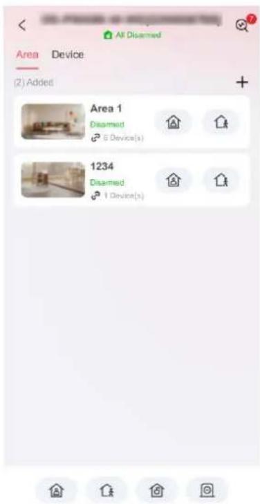
Figure 5-9. Main Page
View Faults
Tap to view faults.
Area Management
Tap + to add an area.
Tap Area to enter the area management page. Refers to Set Arming/Disarming Schedule for details.
Arm/Disarm the Area
Arm or disarm the area manually as you desired.
On the device list page, tap the AX PRO and then log in to the device (if required) to enter the Area page.
Operaons for a Single Area

Area 1
Disarmed
6 Device(s)

Figure 5-10. Single Area
- Away Arming: Tap 📁 to away arm a single area. When all the people in the detecon area leave, turn on the Away mode to arm all zones in the area aer the dened dwell me.
- Stay Arming: Tap 📁 to stay arm a single area. When all the people stays inside the detecon area, turn on the Stay mode to arm all the perimeter burglary detecon set in all the zones of all
areas.
Operaons for Mulple Areas

natural_image
Four circular icons with simple line drawings: a house, a person figure, a house with a sign, and a minus sign (no text or symbols)Figure 5-11. Mulple Area Key
- Away Arming: Tap 📁 to away arm all areas. When all the people in the detecon area leave, turn on the Away mode to arm all zones in all areas aer the dened dwell me.
- Stay Arming: Tap 🔒 to stay arm all areas. When the people stays inside the detecon area, turn on the Stay mode to arm all the perimeter burglary detecon (such as perimeter detector, magnec contacts, curtain detector in the balcony) set in all the zones of all areas. At the meanme, the detectors inside the detecon area are bypassed (such as PIR detectors). People can move inside the area and alarm will not be triggered.
- Disarming: Tap 🔒 to disarm all areas. In Disarm mode, all the zones of all areas will not trigger alarm, no maer alarm events happen or not.
- Silent Alarm: Tap 📄 to silent alarms for all areas.
Device Management
- Tap Device to view linked devices.
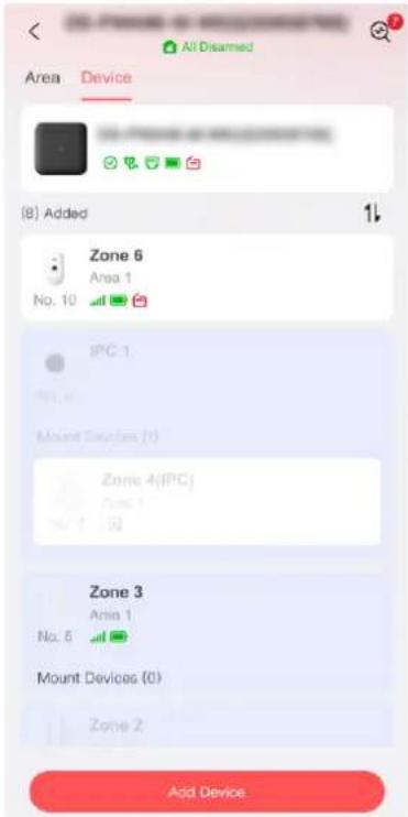
Figure 5-12. Device Page
- Tap Add Device to add a new device.
- Tap a device/zone to enter the management page. You can view device status (e.g. temperature, baery status, single strength, etc.).
- Tap 📍 on the upper right corner to enter the zone sengs page.
- Select a zone type.
You can view the congorable zone types for various detectors through I. Detector Zone Types.
Instant Zone
This Zone type will immediately trigger an alarm event when armed.
Delay Zone
-Exit Delay Time: Exit Delay provides you me to leave through the zone without alarm. You should conrm faults rst, and then the zone is in arming process. If the delay zone is triggered within the exit delay me but it restores before the me ends, the alarm will not be triggered and the zone will be armed.
-Entry Delay Time: Entry Delay provides you me to enter the zone to disarm the system without alarm.
Aer triggering, if the zone is not disarmed or silenced before the entry delay me ends, the zone will alarm.
-Stay Arm Delay Time: Stay arming uses Stay Arm Delay Time to count down.
The system gives Entry/Exit delay me when it is armed or reentered. It is usually used in entrance/exit route (e.g. front door/main entrance), which is a key route to arm/disarm via operang keypad for users.
iNote
Ensure that mer is no longer than 45 seconds in order to comply with EN50131-1.
Panic Zone
24-hour acve zone, whether armed or not. Report panic alarm aer triggering. It is usually used in the sites equipped with panic buon, smoke detector and glass-break detector.
Medical Alarm
24-hour acve zone, whether armed or not. Report medical alarm aer triggering.
Fire Zone
24-hour acve zone, whether armed or not. Report re alarm aer triggering.
Gas Zone
24-hour acve zone, whether armed or not. Report gas alarm aer triggering.
Follow Zone
The zone acts as delayed zone when it detects triggering event during system Entry Delay, while it acts as instant zone otherwise.
Keyswitch Zone
Trigger Type:
-By Trigger Time: Change the arming and disarming status aer each trigger. For example, in the disarmed status, if the zone is triggered, the linked area will be armed. Trigger the zone again and the area will be disarmed.
-By Zone Status: You need to choose to arm or disarm the linked area aer the zone is triggered.
In the case of the lid opened alarm, the arming and disarming operaon will not be triggered.
Disabled
Zone disabled ignoring any alarm event. It is usually used to disable faulty detectors.
24-hour Zone
The zone acvates all the me with sound/light output when alarm occurs, whether it is armed or not. It is usually used in re hazardous areas equipped with smoke detectors and temperature sensors.
Timeout Zone
The zone acvates all the me. When this zone has been triggered or restored and exceeds the set me, an alarm will be generated.
It can be used in places equipped with magnec contacts that require access but for only a short period (e.g., re hydrant box's door or another external security box door).
-Not-Triggered Zone Alarm: If the zone is not triggered for the set me, it will alarm.
-Alarm on Zone Acvated: If the zone is triggered for the set me, it will alarm.
-Retry Time Period: Set the meout period.
- Enable other parameters according to your actual needs.

Note
The supported funcons vary depending on the zone types. Refer to the actual zone to set the funcon.
Arm Mode
If the zone is a public zone (the zone is belongs to more than one areas), you can set arm mode.
And: When all linked areas are armed, the zone will arm. When any of linked areas is disarmed, the zone will disarm.
Or: When any of the linked areas is armed, the zone will arm. When all linked areas are disarmed, the zone will disarm. When the zone is in alarm, the disarmed areas linked with the zone cannot be armed.
Stay Arm Deacvaon
The zone will be automacally bypassed in stay arming.
Chime Zone Enabled
Enable the doorbell. Usually used for door magnec detectors.
Alarm Input 1/Alarm Input 2
Enable the funcon and the set the detector's contact type.
Shock Detecon
Enable the funcon and you can set the shock sensitivity. The higher the number, the more easier to trigger an alarm.
PIR Sensitivity
If the zone is linked with an PIR camera, you can set the PIR sensitivity. The higher the sensitivity, the more easier to trigger an alarm.
Forbid Bypass on Arming
Aer enabled, you cannot bypass zones when arming.
Image Resoluon
Set the captured image resoluon.
Image In Series
Set the captured image number.
Trigger Interval
Set the trigger interval. If a target trigger the zone, an alarm will be triggered and sent every congured me interval until the target geng out of the zone.
Tilt Detecon
Enable the funcon an you can set the lt angle according to actual senarios.
Silent Alarm
Aer enabled, when an alarm is triggered, only the report will be uploaded and no sound is emied.
Double knock
Aer enabled, the me interval can be set. If the same detector is triggered twice or connuously in a period of me, the alarm will be triggered.
Cross Zone
PD6662 is not enabled: You need to set the combined me interval.
When the rst zone is triggered, the system will start ming aer the zone is restored. If the second zone is triggered within the set me, both zones will give alarms. Otherwise, no alarm will be triggered.
If the rst zone is not be restored, both zones will give alarms when the second zone is triggered, regardless of whether the set me has elapsed.
PD6662 is enabled: You need to set the combined me interval.
The rst zone will give an alarm when triggered. If the rst zone is not restored and the second zone is triggered, the system will report the alarm conrmaon.
If the rst zone is restored, the system will start ming. If the second zone is triggered within the set me, the system will report the alarm conrmaon.
If the rst zone is restored, the system will start ming. If the second zone is not triggered within the set me, no informaon will be reported.
Link PIR Camera
You can link some zone to a PIR camera. Check a zone that has a PIR camera.
Sounder Delay Time
The sounder will be triggered immediately (0s) or aer the set me.
LED
You can select to enable/disable the LED funcon.
Acvaon Limit (Time(s))
Set the trigger mes. When the trigger me exceeds the congured mes, it will not upload an alarm.
Polling Rate
Sets the interval at which the system requires the device to return a report. If the device takes longer than the Polling failure Times to determine oine to reply, the system will report faults and the status of device will be shown as oine.
Final Door Exit
Only magnec contacts have this opon.
Aer enabling, when the user use keypads or tag readers to arm:
-Arm With Faults is enabled: During the arming countdown, if the magnec contact is triggered and then restored, the arming process will be terminated immediately aer restoring, and the arming is completed.
-Arm With Faults is disabled: If the magnec contact is triggered and then restored, the linked area immediately arms the delayed zone.
AM Mode
-Alarm Only When ARM: An-masking alarm will be triggered only when the zone is armed.
-Alarm Only When ARM or DISARM: An-masking alarm will be triggered whether the zone is armed or disarmed.
Warning Time Enable
Set the warning me. The warning me countdown will be triggered if the instant zone is triggered during entry delay or the system not be disarmed aer entry delay ends. Local alarms are generated during the period, but no messages will be pushed.
Swinger Limit Acvaons
When the number of mes the infrared detector is triggered exceeds the set value, the alarm will no longer be triggered. (Except for an-masking alarms.).
Dual Zone (Wired Zone)
Aer enabled, when mul transmier detects that the enre zone circuit of the local zone and the extended zone is open circuit, both zones trigger lid opened alarms.
Permanent Deacvaon
-O: The deacvaon funcon is not enabled.
-Lid Only: Only tamper funcon is deactivated, and will not display lid open in the system.
-Enrely: The device is permanently deactivated and will not nofy about alarms or faults for one arming cycle.
One-Time Deacvaon
-O: The deacvaon funcon is not enabled.
-Lid Only: Only tamper funcon is deactivated, and will not display lid open in the system.
-Enrely: The device is permanently deactivated and will not nofy about alarms or faults.
Signal Strength Test
Test the detector's signal strength. If the signal is weak, you should change the detector's position to get a strong signal.
Detecon Zone Test
Simulate intrusions into the room from its doors, windows or other possible entrances to check if alarms can be triggered. The indicator will turn blue when an alarm is triggered.
Find Me
Click Find Me and the detector's indicator will ash or it will make a sound.
User Guide
View the detector's user manual.
- If required, link a PIRCAM or a camera for the zone.
- Click OK.
Zone Deacvaon
When the area is armed, you can bypass a parcular zone as you desired.
Before You Start
Link a detector to the zone.
Steps
- On the device list page, tap the AX PRO and then log in to the device (if required) to enter the Area page.
- Tap Device.
- Tap a zone in the Device tab.
- Tap to enter the Sengs page.
- Set Permanent Deacvaon and One-Time Deacvaon.
Permanent Deacvaon
-O: The deacvaon funcon is not enabled.
-Lid Only: Only tamper funcon is deactivated, and will not display lid open in the system.
-Enrely: The device is permanently deactivated and will not nofy about alarms or faults for one arming cycle.
One-Time Deacvaon
-O: The deacvaon funcon is not enabled.
-Lid Only: Only tamper funcon is deactivated, and will not display lid open in the system.
-Enrely: The device is permanently deactivated and will not nofy about alarms or faults.
User Management
The administrator and the installers can manage users. If you are the administrator, you can add, edit, and delete users, and assign dierent permissions to the newly-added users.
Steps
iNote
There are three types of users for the AX PRO, including administrator (or owner), operator, and installer (or seer). Dierent types of users have dierent permissions for accessing the funconality of the AX PRO.
- On the device list page, tap → Share.
- Tap Device and tap the AX PRO.
- Tap → Authorizaon Service to enter the sengs page.
-
Tap Share with User and invite a user.
-
Scan QR code to invite a user.
— Enter email address/mobile phone number to invite a user. -
Select a user in the list.
-
Tap Next to invite the user.
iNote
The recipient need to accept the invitaon.
- Tap Next to invite the user.
- Tap Device and tap the AX PRO.
- Tap → User Management to enter the sengs page.
- Tap Add and set the basic informaon.
User Property
-Lifeme: Permanent use. Congurable with full user permission.
-One-Time User: Expired aer arming or disarming once, or automacally expires aer 24 hours. No duress code permission. No keyfobs and tags permission.
-Valid Time Period: Set the length of use for this user through me conguraon, congorable with full user permissions.
Phone Number
Enter the phone number for the user. The mobile phone number should be with internaonal area code.
Keypad
Set the keypad's operaon passcode and duress passcode. The user can use the passcode to control the keypad.
Permission
Set the permissions for the user.
| iNoteOnly the administrator can do such an operaon. | |
| You can link area for the user to arm, disarm/silence alarm.Automaon Device Control: If enable the funcon, the user can control the relay open/closed. | |
| Linked Area | If the target user is an operator, tap the target user on the user list and then tap to set the area linked to the target user. |
| iNoteOnly the administrator can do such an operaon. | |
| Change Keypad Password | If the target user is an administrator, an installer or an operator, you can tap the target user on the user list and then tap Change Keypad Password to set the keypad password to the target user. |
| iNoteThe password (PIN code) is allowed to be 4 to 6 digits. No number is disallowed, with 10,000 to 100,000 diers, and no limit of the digit combinaon.Aer you add one keypad, you can add PIN code (Keypad Password) in the user menu. When you click in the input box, there will be indicaon shows that 4 to 6 numbers allowed. This is the same for each user | |
| Change Duress Password | If the target user is an administrator or an operator, you can tap the target user on the user list and then tap Change Duress Password to set the duress password to the target user. |
| iNoteIf under duress, you can enter the duress code on the keypad to arm and disarm area(s) and upload a duress alarm. | |
| Card/Tag/Keyfob | An administrator, an installer or an operator can use cards/tags or keyfob. |

Note
- Conguraon items and user permission will vary according to the user type.
-
You can view linked Card/Tag and Wireless Keyfob of the user.
-
Tap Next and set the message/phone call push parameters.
-
Slide the block to enable/disable the event. When the device event is triggered, a message or phone call will be sent to the reserved phone number.
Card/Tag Management
Aer adding cards/tags to the wireless AX PRO, you can swipe the card/tag to arm or disarm all the detectors added to specific area(s) of the AX PRO, and silence alarms.
iNote
The tag ID/PIN is a 32 bit long integer, and the variant could be 42949672956.
Steps
- On the device list page, tap the AX PRO and then log in to the device (if required) to enter the page.
- Tap Device and tap the AX PRO.
- Tap → User Management to enter the sengs page.
- Tap a user to enter the conguraon page.
- Tap tag/keyfob.
- Tap Add.
-For Keyfob: scan the QR code of the keyfob to add.
-For Tag: When hearing the voice prompt "Swipe Tag", you should present the tag on the AX PRO tag presenng area.
When hearing a beep sound, the tag is recognized.
The tag will be displayed on the tag list.
- Oponal: Tap a keyfob/tag to enter the conguraon page and you can set the keyfob/tag parameters.
i Note
- If you log in as an installer, skip this step. Eding tag name is only available to administrator.
-
The name should contain 1 to 32 characters.
-
Select the tag type.
- Oponal: Tap Delete Device to delete the keyfob/tag.
Device Informaon
You can change language and select me zone.
Steps
- On the device list page, tap the AX PRO and then log in to the device (if required) to enter the page.
-
Tap Device and tap the AX PRO.
-
Tap ➕ System Sengs to enter the sengs page.
-
You can view device basic informaon, select device language, me, and set control panel opons.
Panel LED
Enable/Disable panel functional LED.
Arm LED/Cloud LED
Enable arm/cloud LED indicator.
Fault LED Stays On When Armed
Aer arming, the fault indicator remains on.
Voice Prompt
If the opon is enabled, the AX PRO will enable the voice prompt.
Panel Volume
The available system volume range is from 0 to 10.
Fault Prompts When Arming
Voice prompt of faults when the system is armed.
Enable/Disable sound prompt. Set the panel volume and sound prompt opons.
Alarm Prompts
Voice prompt of faults when an alarm is triggered.
Fault Prompts When Armed
The system will make voice prompts when the control panel is armed.
Fault Prompts When Arming
The system will make voice prompts when arming.
Fault Prompts When Disarmed
The system will make voice prompts when the control panel is disarmed.
Fault Prompts When Disarming
The system will make voice prompts when disarming.
Tamper Alarm
When a tamper alarm is triggered, a voice prompt will be triggered.
System Alarm Duraon
Set linked alarm voice prompt lasng me.
Service Sengs
Congure the fault check, arming and regional cercaon.
Steps
-
On the device list page, tap the AX PRO and then log in to the device (if required) to enter the page.
-
Tap Device and tap the AX PRO.
-
Tap → Service to enter the sengs page.
-
You can set the service parameters.
Re-Arm on Restore
While enabled, aer the detector is bypassed, if its faults are restored and the linked area is armed, the detector will automacally arm.
Audible Tamper Alarm
While enabled, the system will alert with buzzer for the tamper alarm. Regardless of whether it is enabled or not, the tamper alarm will be normally pushed to Cloud (for APP) and ARC.
Jamming Sensivity Sengs
The device will detect RF interference and push messages when the RF interference interferes with communicaon. You can adjust the detecon sensitivity.
Moon detectors include all PIR detectors.
-Immediate Aer Alarm: Moon detectors automatically restores immediately aer the alarm and reports to Cloud (for APP) and ARC.
-Aer Disarm: Moon detectors automacally restores aer disarming and reports to Cloud (for APP) and ARC
Fault Checklist when Arming
The system will check if the device has the faults in the checklist during the arming process. The fault check here is only for the control panel in the normal status.
The system determines whether to check the faults listed on the page. The system will only check the fault that is selected.
Baery Status
Baery Lost
If the opon is enabled, when baery is disconnected, the device will upload events.
Low Baery
If the opon is enabled, when baery is in low baery status, the device will upload events.
Zone/Peripherals Low Baery
If the opon is enabled, when zone or peripherals' baery is in low baery status, the device will upload events.
Power Supply Availability
Panel Mains Power Lost
If the opon is enabled, an alarm will be triggered when the control panel main supply is disconnected.
To compliant the EN 50131-3, the report dealy duraon should be 10 s.
Peripheral Mains Power Lost
If the opon is enabled, when the peripheral's main power is lost, the alarm will be
triggered.
Device Connecon
Zone/Peripherals Poll Failure/Oine
If the opon is enabled, when zone or peripherals' conncon is lost, the alarm will be triggered.
IP Camera Disconnecon
If the opon is enabled, when the network camera's conncon is lost, the alarm will be triggered.
Server Connecon
Ethernet Lost
If the opon is enabled, when the wired network is disconnected or with other faults, the alarm will be triggered.
Wi-Fi Lost
If the opon is enabled, when the Wi-Fi is disconnected or with other faults, the alarm will be triggered.
Cellular Lost
If the opon is enabled, when the cellular data network is disconnected or with other faults, the alarm will be triggered.
Lid Status
If the opon is enabled, an alarm will be triggered when the control panel is lid open.
ARC Connecon
If the opon is enabled, an alarm will be triggered when the ARC (Alarm Receiving Center) conncon contains fault.
Jamming Detecon
If the opon is enabled, an alarm will be triggered when the control panel detectng jamming.
Zone Triggered Fault
If the opon is enabled, an alarm will be triggered when the control panel's zone triggering contains fault.
Panel-Server Polling Interval
Set the me interval when the control panel's server is polling.
Delay of Server Connecon Failure
If the control panel server cannot connected for the delayed me duraon, conncon will failed.
Panel Fault Check
If the opon is enabled, an event will be reported aer the delayed me.
Power Saving Mode
While enabled, the main power supply is o, Wi-Fi enters low power consumption, 4G closes, tag reading fails. LED is o, and voice prompt is o.
PD6662
PD6662 is applicable to the UK market. If this funcon is enabled, the arming funcon and alarm logic of the control panel will change.
Enable PD6662 standard. Funcons that do not meet the standard will not take eect.
Communicaon Fault Sending Delay
The delay me while the ATP communicaon fault reports to ARC.
Panel Lockup Buon
All funcons of AX PRO will be frozen aer it is enabled. This funcon can only be enabled by users with installer permission.
Network Camera
Add Cameras to the AX PRO
Steps
- On the device list page, tap the AX PRO and then log in to the device (if required).
- Tap Device → Add Device → SADP Scan and Add Network Camera to enter the page.
SADP Scanning
Scan all network cameras in the same LAN. A list will pop up aer scanning. You can directly check to add cameras in the list.
Manually Add
If SADP scanning cannot nd a camera, you can tap Manually Add and enter IP address, port, the user name and password of the camera. Tap Conrm.
Set Video Parameters
Steps
- On the device list page, tap the AX PRO and then log in to the device (if required).
- Tap a camera and tap ☐ to enter the page.
- Set the video parameters.
Stream Type
Main Stream: Being used in recording and HD preview, it has a high resolution, code rate and picture quality.
Sub-Stream: It is used to transmit network and preview pictures as a video streaming with features of lower resolution, bit rate and picture quality.
Bitrate Type
Select the Bitrate type as constant or variable.
Resoluon
Select the resolution of the video output.
Bitrate
The higher value corresponds to the higher video quality, but the beer bandwidth is required.
Before Alarm
The recording me length before the alarm.
Aer Alarm
The recording me length aer the alarm.
Set Arming/Disarming Schedule
Steps
- On the device list page, tap the AX PRO and then log in to the device (if required) to enter the page.
- Tap Area to enter the page.
- Tap an area in the list, and tap Sengs.
- Set parameters:
Add to Home Shortcut
Enable the funcon and the area shortcut will be displayed on the home page.
Late to Disarm
Enable the funcon and set the me. If the alarm is triggered aer the congured me, the person will be considered as late.
Auto Arm
Enable the funcon and set the arming start me. The zone will be armed according to the congured me.

Note
The auto arming me and the auto disarming me cannot be the same.
-Forced Auto Arm:
While the funcon is enabled, faults will be ignored when the system is automacally armed.
-Auto Arming Sound Prompt:
Aer enabled, the buzzer beeps slowly 2 minutes before the auto arming starts, and beeps rapidly 1 minute before the auto arming starts.
Aer disabled, the buzzer will not beep before auto arming.
Auto Disarm
Enable the funcon and set the disarming start me. The zone will be disarmed according to the congured me.

Note
The auto arming me and the auto disarming me cannot be the same.
-Weekend Excepon:
Enable the funcon and the zone will not be armed in the weekend.
-Holiday Excepon:
Enable the funcon and the zone will not be armed/disarmed in the holiday. You should set the holiday schedule aer enabling. Up to 12 holiday groups can be set.
Communicaon
Wired Network
Steps
- On the device list page, tap the AX PRO and then log in to the device (if required) to enter the page.
- Tap Device and tap the AX PRO.
- Tap → Network Sengs → Ethernet to enter the sengs page.
- Set the parameters.
– Automac Sengs: Enable DHCP and set the HTTP port.
- Manual Setngs: Disabled DHCP and set IP Address, Subnet Mask, Gateway Address, DNS Server Address.
-
Oponal: Set correct DNS server address if the device needs to visit Hik-Connect server via a domain name.
-
Tap Save.
Wi-Fi Conguraon
Steps
- On the device list page, tap the AX PRO and then log in to the device (if required) to enter the page.
- Tap Device and tap the AX PRO.
- Tap → Network Sengs → Wi-Fi to enter the sengs page.
- Tap a Wi-Fi to connect in the list.
Cellular Sengs
Steps
- On the device list page, tap the AX PRO and then log in to the device (if required) to enter the page.
- Tap Device and tap the AX PRO.
- Tap → Network Sengs → Cellular to enter the sengs page.
-
Select a SIM card and enable Cellular.
-
Set parameters including the access number, user name, access password, APN, MTU, PIN, and IMSI.
Access Number
Input the operator dialing number.
iNote
Only the private network SIM card user needs to enter the access number.
User Name
Ask the network carrier and input the user name.
Password
Ask the network carrier and input the password.
APN
Ask the network carrier to get the APN informaon and input the APN informaon.
- You can also enable data limit funcon and set the trac.
- Edit Used Trac This Month and Trac Threshold.
Used Trac This Month
The used data will be accumulated and displayed in this text box.
Trac Threshold
You can enable the funcon and set the data threshold every month. If data usage is more than the congured threshold, an alarm will be triggered and uploaded to the alarm center and mobile client.
- Tap Network Test to test the network.
- Tap Save.
Network Service Sengs
- On the device list page, tap the AX PRO and then log in to the device (if required) to enter the page.
- Tap Device and tap the AX PRO.
- Tap 📋 → Network Service to enter the sengs page.
- Set the HTTP Port and tap Save.
Cloud Service Sengs
Steps
- On the device list page, tap the AX PRO and then log in to the device (if required) to enter the page.
- Tap Device and tap the AX PRO.
- Tap 📍 → Cloud Service to enter the sengs page.
- Select the Communicaton Mode.
Ethernet
The system will select wired network.
Wi-Fi
The system will select Wi-Fi.
Cellular
The system will select cellular data network.
- Enable Periodic Test. Enter the periodic test interval.
- Tap Save.
Alarm Receiving Center (ARC)
You can set the alarm receiving center's parameters and all alarms will be sent to the congured alarm center.
Steps
- On the device list page, tap the AX PRO and then log in to the device (if required) to enter the page.
- Tap Device and tap the AX PRO.
- Tap → ARC Sengs to enter the sengs page.
- Select an ARC and enable it.
Connecon Type
Set the conncon type as IP or Serial Port.
Protocol Type
Select the Protocol Type as ADM-CID, ISUP, SIA-DCS, *SIA-DCS, *ADM-CID, CSV-IP, FSK Module or RDC Module to set uploading mode.
Connecon Mode
Select the Transmission Mode as TCP or UDP. UDP is recommended by the SIA DC-09 standard.
Communicaon Channel
Ethernet
The system will select wired network.
Wi-Fi
The system will select Wi-Fi.
Cellular
The system will select cellular data network.
Server Address Type
Select the Address Type as IP Address and Domain Name. Enter server address/domain name, port number and account code.
Polling Opon
Set the polling rate with the range from 10 to 3888000 seconds. The system will report fault if
the me is over the limit. The status of device will be shown as oine.
Periodic Test
Aer enabling, you can set the me interval, seng how oen to send a test event to the ARC to ensure the conncon.
Retry Timeout Period
Aer the selected me, the system will retry to transmit.
Aempts
Set the number of retry aempts.
Companies
Select the support company as None, Hungary-Mul Alarm Receiving Company or French Alarm Receiving Company.
PIRCAM Picture Upload Mode
When the control panel uploads the alarm informaon, it will return the picture and video address for you to view.
Push Nocaons
For details, see Push Nocaons.
GMT
Enable the Greenwich Mean Time.
ARC Push Nocaons
When an alarm is triggered, if you want to send the alarm nocaon to the mobile phone, you can set the nocaon push parameters.
Steps
- On the device list page, tap the AX PRO and then log in to the device (if required) to enter the page.
- Tap Device and tap the AX PRO.
- Tap → ARC Sengs to enter the sengs page.
- Select an ARC and enable it.
- Tap Push Nocaons and enable the funcon.
Alarm Event
Zone Alarm
The device will push nocaons when the zone alarm (on web client, soware client or mobile client) is triggered or the zone peripherals alarm is triggered or restored.
Panel Lid Opened
The device will push nocaons when lid opened alarm of the control panel is triggered or restored.
Peripherals Lid Opened
The device will push nocaons when lid opened alarm of any peripheral is triggered or restored.
Keypad/Keyfob/APP Panic Alarm
The device will push nocaons when panic alarm on keypads/keyfobs/APP is triggered or restored.
Keypad/Keyfob Medical Alarm
The device will push nocaons when medical alarm on keypads or keyfobs is triggered.
Keypad Fire Alarm
The device will push nocaons when re alarm on keypads is triggered or a user presses the re alarm key on the keypad.
Camera Events
The device will push nocaons when alarm is triggered in network cameras(using HIKVISION protocol).
PIRCAM Gif
The video and pictures generated by PIR cameras will be uploaded to the alarm receiving center.
Video Clips
The video and pictures generated by network cameras will be uploaded to the alarm receiving center.
Fault Event
Panel Status (Power and Baery)
The device will push nocaons when the control panel power/baery status is changed.
Panel Status (Communicaon)
The device will push nocaons when the control panel communicaon status is changed.
Zone Status
The device will push nocaons when any zone status is changed.
Peripherals Status
The device will push nocaons when any peripheral status is changed.
Operaon Event
System Operaon
The device will push nocaons when the user operate the control panel.
System Event
Panel Upgrade
The device will push nocaons when the control panel is upgraded.
- Tap APP and check events. The selected events will be pushed in the APP as important alarms.
ARC Disconnecon Report Delay
The device will push nocaons when Alarm Receiving Center is disconnected.
-
Tap Phone Call and SMS.
-
Tap + to enter the phone number.
- Tap the added phone number to enable Phone Call and SMS according to your need.
iNote
Do not congregate the phone number to the SIM card inserted in the device itself, otherwise abnormal charges will occur and the user will have to bear them.
(For Phone Call) Set number of calling when the phone is unanswered.
(For SMS) Set Arming Permission, Disarming Permission and Silence Alarm Permission for areas.
Common Message
You can enter message content. When the alarm is triggered, your customized content will be added at the beginning of the message sent by the system.
Common Voice
You can import a new audio. When the alarm is triggered, your customized voice will be added at the beginning of the content of the phone dialed by the system. You can also tap Clear to delete audios
iNote
Only WAV format is supported, up to 512 KB and 15 s.
- Check nocaons.
Nocaon by SMS
Steps
- On the device list page, tap the AX PRO and then log in to the device (if required) to enter the page.
- Tap Device and tap the AX PRO.
- Tap → Push Nocaons to enter the sengs page.
- Edit a message content and tap Save.
The message and alarm informaon will be sent to the user's reserved mobile phone number that has permissions.
Nocaon by Email
Steps
- On the device list page, tap the AX PRO and then log in to the device (if required) to enter the page
- Tap Device and tap the AX PRO.
- Tap → Nocaon by E-mail to enter the sengs page.
-
Enable Email 1.
-
Enter the sender name, sender email address, SMTP server address, SMTP port, user name and password.
iNote
It is recommended to use Gmail and Hotmail for sending mails.
Only if the zone is linked with a network camera, the alarm email will be aached with alarm video.
-
Select the encrypon type as None, SSL or TLS.
-
Enable Server Authencaon. When the funcon is enabled, when the server ask an authencaon, the user name and password will be checked.
-
Enter receiver name and receiver email address. Tap Receiver Address Test to test whether the email address is correct.
-
Tap Save.
-
Oponal: Congure Email 2 in the same order. You can choose whether to set email 2 as a backup mailbox.
iNote
Video and picture reviews will be sent to both mailboxes. If Email 2 is set as a backup mailbox, the system will push emails to Email 2 only if Email 1 fails to receive.
FTP Sengs
Steps
-
On the device list page, tap the AX PRO and then log in to the device (if required) to enter the page.
-
Tap Device and tap the AX PRO.
-
Tap ➕ FTP Sengs to enter the sengs page.
-
Select the FTP type as Main FTP or Standby FTP, and enable FTP.
-
Congure the FTP parameters
Protocol Type
FTP and SFTP are selectable. The les uploading is encrypted by using SFTP protocol.
Server Type
Select IP Address or Domain Name as the server address type.
Server Address / Domain Name / Port
The FTP server address and corresponding port.
Enable Anonymity
The FTP user should have the permission to upload pictures. If the FTP server supports picture uploading by anonymous users, you can enable anonymous to hide your device informaon during uploading.
Directory Structure
The saving path of snapshots in the FTP server.
- Tap Save.
Intercom Service
You can congregate the Intercom service for an intercom sounder.
Before You Start
You should enroll an intercom sounder rst.
Only one sounder can be set as the intercom sounder.
Steps
- On the device list page, tap the AX PRO and then log in to the device (if required) to enter the page.
- Tap Device and tap the AX PRO.
- Tap ➕ Intercom Service to enter the sengs page.
- Slide to enable the funcon.
- Set intercom type.
STD-SIP
The control panel will use ARC and standard SIP server.
IP Receiver Pro
The control panel supports intercom of cloud service and ISUP protocol.
ISUP
The control panel uses the ISUP protocol through the Hik-Central APP.
ESI-SIP
The control panel uses the ESI-SIP server.
- Select an intercom sounder and alarm verify priority and tap Save.
Device Maintenance
You can reboot the device.
Steps
- On the device list page, tap the AX PRO and then log in to the device (if required) to enter the page.
- Tap Device and tap the AX PRO.
- Tap →Maintenance → Restart.
The AX PRO will reboot.
- Tap → Maintenance → Reset.
You can reset the AX PRO partly or reset to default sengs.
- Oponal: Tap → Maintenance → Remote Log Collecon to enable the funcon.
Remote Log Collecon is for geng logs relang to the device. When this is enabled, our technical support will be able to collect logs relang to the device remotely and upload them to
our server for troublesomeong. You can set the validity period according to actual needs. This funcon will be disabled aer the set validity period.
-
Tap →Maintenance →Control Panel Upgrade to upgrade the control panel, or tap →Maintenance →Detector & Peripheral Upgrade to upgrade detectors and peripherals.
-
Tap →Maintenance →Walk Test to test the whether the device works properly or not. Slide Enable. Trigger the detector in each zone.
iNote
Only when all the detectors are without fault, you can enter the mode TEST mode.
- Tap →Maintenance →Device Debugging.
Tamper Alarm on HPP Login
Aer this funcon is enabled, the device lid opened alarm (tamper alarm) takes eect when installer login. (By default, the lid opened alarm (tamper alarm) does not take eect when the installer login.)
Event Log for Cellular Service
If enabled, you can get the log when using the cellular service.
STA/AP Mode Switch
You can make the AX PRO connect to Wi-Fi through APP.
Steps
- On the device list page, tap the AX PRO and then log in to the device (if required) to enter the page.
- Tap Device and tap the AX PRO.
- Tap →Network Sengs →Wi-Fi.
- Follow the instrucons on the page and change the AX PRO to the AP mode. Tap Next.
- Select a stable Wi-Fi for the device to connect.
- Back to conguraon page to enter the Wi-Fi password and tap Next.
- Tap Connect to a network and wait for conncon.
Aer the conncon is completed, the AX PRO will prompt to exit AP mode and automacally switch to STA mode.
Check Alarm Nocaon
When an alarm is triggered, and you will receive an alarm nocoon. You can check the alarm informaon from the mobile client.
Before You Start
- Make sure you have linked a zone with a detector.
- Make sure the zone is not bypassed.
- Make sure you have not enabled the silent zone funcon.
Steps
-
Tap Nocaons in the mobile client to enter the page. All alarm nocaons are listed in Nocaon page.
-
Select an alarm and you can view the alarm details.
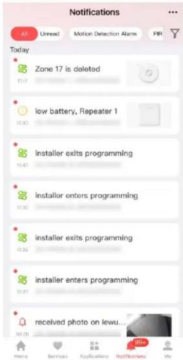
Figure 5-13. Nocaon Page
-
Oponal: If the zone has linked a camera, you can view the playback when the alarm is triggered.
-
Oponal: Tap to search events by dates or devices.
5.3 Set-up with the Web Client
Steps
- Connect the device to the Ethernet.
- Search the device IP address via the client soware or the SADP soware.
- Enter the searched IP address in the address bar.
- Use the acvaon user name and password to login.
iNote
The user name and the password are the ones when acvang via Hik-Connect or Hik-Partner Pro.
You can view the device, area, zone and so on status on the overview page.
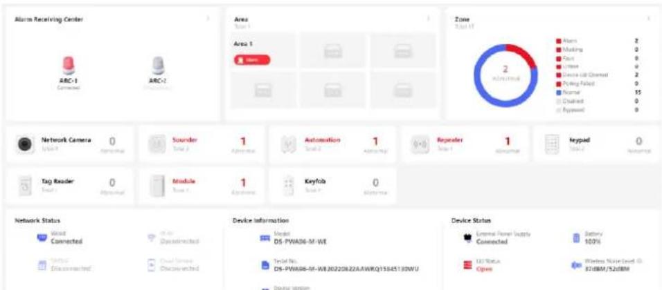
Figure 5-14. Web Main Page
5.3.1 User Management
The administrator and the installers can manage users. If you are the administrator, you can add, edit, and delete users, and assign dierent permissions to the newly-added users.
Click Conguraon → User Management to enter the page.

Note
There are three types of users for the AX PRO, including administrator (or owner), operator, and installer (or seer). Dierent types of users have dierent permissions for accessing the funconality of the AX PRO.
Add User
Steps
- Click Conguraon → User Management to enter the page.
- Click +Add.
- Congure the user parameters.
User Name
Create a user name for the user.
User Property
-Permanent: Permanent use. Congurable with full user permission.
-One-Time User: Expired aer arming or disarming once, or automacally expires aer 24 hours. No duress code permission. No keyfobs and tags permission.
-Eecve Period: Set the length of use for this user through me conguraon, congorable with full user permissions.
Phone
Enter the phone number for the user. The mobile phone number should be with internaonal area code.
- Congure the keypad parameters for the user.
Operaon Code
Create an operaon code for the keypad that the user will use.
Duress Code
Aer entering the duress code, the system will upload the duress alarm to the alarm receiving center. No audible or visual alarm.
-
Congure the user's permission. Check the area that the user can arm/disarm or auto control.
-
Tap Next and set the message/phone call push parameters.
-
Slide the block to enable/disable the event. When the device event is triggered, a message or phone call will be sent to the reserved phone number.
You can also set the Filtering Interval Time. The interval between calls for the same alarm.
- Click OK to add the user.
Edit User
Steps
-
Click Conguraon → User Management to enter the page.
-
Click to the right of a user to edit user parameters.
Basic Informaon
You can choose to enable/disable the user, edit the user password, phone number, keypad operaon code and permissions.
Message Sengs
Slide the block to enable/disable the event. When the device event is triggered, a message or phone call will be sent to the reserved phone number.
You can also set the Filtering Interval Time. The interval between calls for the same alarm.
Keyfob&Tag
You can add, delete, enable or disable keyfobs and tags.
- Click Save.
Delete User
Steps
-
Click Conguraon → User Management to enter the page.
-
Click ☐ to the right of a user to delete user parameters. You can also check users in the list and click Delete to delete users in batch.

The administrator and the installer cannot be deleted.
5.3.2 Area Management
You can set the area parameters on the page.
Steps
- Click Area to enter the page.
- Click + on the right of the page to enter the Add Area page.
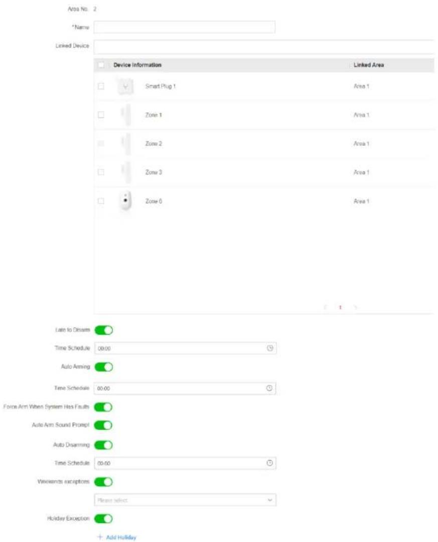
Figure 5-15. Area
- Create a name for the area.
- Check the linked device from the list. The checked devices will be linked with the area.
- Set parameters according to your actual needs.
Late to Disarm Nocaon
Enable the funcon and set the me. If the alarm is triggered aer the congured me, the person will be considered as late.
Auto Arming
Enable the funcon and set the arming start me (Time Schedule). The zone will be armed according to the congured me.

Note
The auto arming me and the auto disarming me cannot be the same.
-Forced Arm When System has Faults:
While the funcon is enabled, faults will be ignored when the system is automacally armed.
-Auto Arm Sound Prompt:
Aer enabled, the buzzer beeps slowly 2 minutes before the auto arming starts, and beeps rapidly 1 minute before the auto arming starts.
Aer disabled, the buzzer will not beep before auto arming.
Auto Disarming
Enable the funcon and set the disarming start me(Time Schedule). The zone will be disarmed according to the congured me.

Note
The auto arming me and the auto disarming me cannot be the same.
Weekend Excepon:
Enable the funcon and the zone will not be armed in the weekend.
Holiday Excepon:
Enable the funcon and the zone will not be armed/disarmed in the holiday. You should click
+ Add Holiday to set the holiday schedule aer enabling. Up to 12 holiday groups can be set.
6. Click OK.
Aer the area is added, you can tap , , , , to stay arm, away arm, disarm,
or delete the area. Or tap , , , , , to hatch congure stay arming, away
arming, disarming, clearing alarm, and refreshing.
5.3.3 Device Management
You can edit areas and manage the enrolled devices including detector, sounder, keypad, etc. in this secon.
Add Mul-Transmier
You can set the parameters of the transmier.

i Note
Aer adding a transmier, you can add a wired zone.
Steps
- Click Device to enter the page.
- Click + Add Device. In the Wired Device area, click Manually Add.
- Select device type as Zone or Automaon.
- Set the Main Device Type as Mul Transmier and select Main Device Name.
- Tap Next and set device.
- On the device list page, select a zone and click ⚙ to enter the conguraon page.
- Click Save.
Add Zone
Steps
- Click Device to enter the page.
- Click + Add Device. In the Wireless Device area, click Manually Add.

Aer adding a transmier, you can add a wired zone.
- Select device type as Zone, and set the device serial No. and model.
- Tap Next and set device.
- On the device list page, select a zone and click ⚙ to enter the conguraon page.
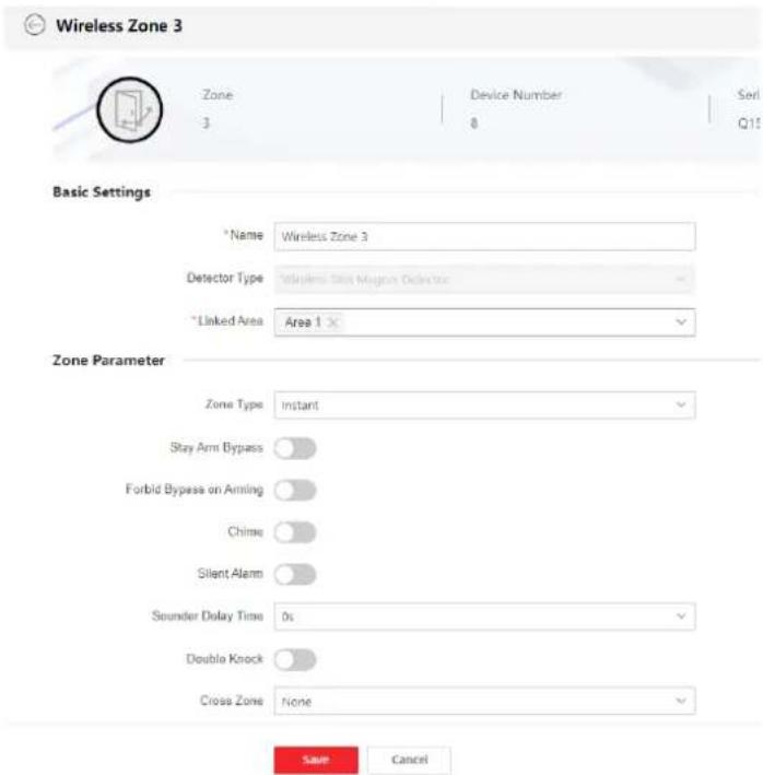
Figure 5-16. Zone Sengs
- Edit the zone name.
- Check linked areas.
iNote
- Only enabled areas will be listed.
● The newly added peripheral is linked to area 1 by default.
7. Select a zone type.
You can view the congorable zone types for various detectors through I. Detector Zone Types.
Instant Zone
This Zone type will immediately trigger an alarm event when armed.
Delay Zone
-Exit Delay Time: Exit Delay provides you me to leave through the zone without alarm.
You should conrm faults rst, and then the zone is in arming process. If the delay zone is triggered within the exit delay me but it restores before the me ends, the alarm will not be triggered and the zone will be armed.
-Entry Delay Time: Entry Delay provides you me to enter the zone to disarm the system without alarm.
Aer triggering, if the zone is not disarmed or silenced before the entry delay me ends, the zone will alarm.
-Stay Arm Delay Time: Stay arming uses Stay Arm Delay Time to count down.
The system gives Entry/Exit delay me when it is armed or reentered. It is usually used in entrance/exit route (e.g. front door/main entrance), which is a key route to arm/disarm via operang keypad for users.
iNote
Ensure that mer is no longer than 45 seconds in order to comply with EN50131-1.
Panic Zone
24-hour acve zone, whether armed or not. Report panic alarm aer triggering. It is usually used in the sites equipped with panic buon, smoke detector and glass-break detector.
Medical Alarm
24-hour acve zone, whether armed or not. Report medical alarm aer triggering.
Fire Zone
24-hour acve zone, whether armed or not. Report re alarm aer triggering.
Gas Zone
24-hour acve zone, whether armed or not. Report gas alarm aer triggering.
Follow Zone
The zone acts as delayed zone when it detects triggering event during system Entry Delay, while it acts as instant zone otherwise.
Keyswitch Zone
New Key Zone Trigger Type:
-Trigger Times: Change the arming and disarming status aer each trigger. For example, in the disarmed status, if the zone is triggered, the linked area will be armed. Trigger the zone again and the area will be disarmed.
-Zone Status: You need to choose to arm or disarm the linked area aer the zone is triggered.
In the case of the lid opened alarm, the arming and disarming operaon will not be triggered.
Disabled Zone
Zone disabled ignoring any alarm event. It is usually used to disable faulty detectors.
24-Hour
The zone acvates all the me with sound/light output when alarm occurs, whether it is armed or not. It is usually used in re hazardous areas equipped with smoke detectors and temperature sensors.
Timeout Zone
The zone acvates all the me. When this zone has been triggered or restored and exceeds the set me, an alarm will be generated.
It can be used in places equipped with magnec contacts that require access but for only a short period (e.g., re hydrant box's door or another external security box door).
- Set other parameters according to your actual needs.

Note
The supported funcons vary depending on the zone types. Refer to the actual zone to set the funcon.
Arm Mode
If the zone is a public zone (the zone is belongs to more than one areas), you can set arm mode.
And: When all linked areas are armed, the zone will arm. When any of linked areas is disarmed, the zone will disarm.
Or: When any of the linked areas is armed, the zone will arm. When all linked areas are disarmed, the zone will disarm. When the zone is in alarm, the disarmed areas linked with the zone cannot be armed.
Stay Arm Deacvaon
The zone will be automacally bypassed in stay arming.
Cross Zone
PD6662 is not enabled: You need to set the combined me interval.
When the rst zone is triggered, the system will start ming aer the zone is restored. If the second zone is triggered within the set me, both zones will give alarms. Otherwise, no alarm will be triggered.
If the rst zone is not be restored, both zones will give alarms when the second zone is triggered, regardless of whether the set me has elapsed.
PD6662 is enabled: You need to set the combined me interval.
The rst zone will give an alarm when triggered. If the rst zone is not restored and the second zone is triggered, the system will report the alarm conrmaon.
If the rst zone is restored, the system will start ming. If the second zone is triggered within the set me, the system will report the alarm conrmaon.
If the rst zone is restored, the system will start ming. If the second zone is not triggered within the set me, no informaon will be reported.
Forbid Bypass on Arming
Aer enabled, you cannot bypass zones when arming.
Chime
Enable the doorbell. Usually used for door magnec detectors.
Silent Alarm
Aer enabled, when an alarm is triggered, only the report will be uploaded and no sound is emied.
Double knock
Aer enabled, the me interval can be set. If the same detector is triggered twice or connuously in a period of me, the alarm will be triggered.
Sounder Delay Time
The sounder will be triggered immediately (0s) or aer the set me.
Final Door Exit
Only magnec contacts have this opon.
Aer enabling, when the user use keypads or tag readers to arm:
-Arm With Faults is enabled: During the arming countdown, if the magnec contact is triggered and then restored, the arming process will be terminated immediately aer restoring, and the arming is completed.
-Arm With Faults is disabled: If the magnec contact is triggered and then restored, the linked area immediately arms the delayed zone.
AM Mode
-Alarm Only When ARM: An-masking alarm will be triggered only when the zone is armed.
-Alarm Only When ARM or DISARM: An-masking alarm will be triggered whether the zone is armed or disarmed.
Warning Time Enable
Set the warning me. The warning me countdown will be triggered if the instant zone is triggered during entry delay or the system not be disarmed aer entry delay ends. Local alarms are generated during the period, but no messages will be pushed.
Swinger Limit Acvaons
When the number of mes the infrared detector is triggered exceeds the set value, the alarm will no longer be triggered. (Except for an-masking alarms.).
Dual Zone (Wired Zone)
Aer enabled, when mul transmier detects that the enre zone circuit of the local zone and the extended zone is open circuit, both zones trigger lid opened alarms.
-
If required, link a PIR camera or a camera for the zone.
-
Click Save.
Add Sounder
The sounder is enrolled to the AX PRO via the wireless receiver module, and the 868 Mhz wireless sounder can be enrolled to the hybrid AX PRO via the wireless receiver that is at the address of 9.
Steps
-
Click Device to enter the page.
-
Click + Add Device. In the Wireless Device area, click Manually Add.
-
Select device type as Sounder, and set the device serial No. and model.
-
Tap Next and set device.
-
On the device list page, select a zone and click ⚙️ to enter the conguraon page.
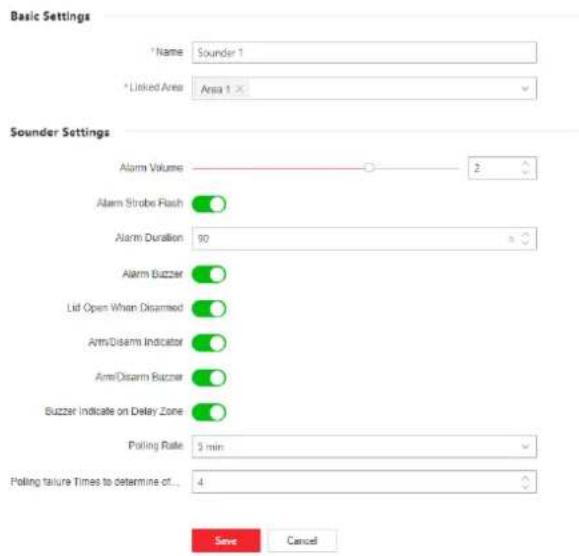
Figure 5-17. Sounder Sengs
Linked Area
Only enabled areas will be listed.
The newly added peripheral is linked to area 1 by default.
Alarm Volume
The available alarm volume range is from 0 to 3 (funcon varies according to the model of device).
Alarm Strobe Flash
Enable alarm strobe light.
Alarm Duraon
The available alarm duraon range is from 10 to 900 s.
Alarm Buzzer
Enable alarm buzzer.
Lid Open When Disarmed
When the linked area is disarmed, there is a lid opened alarm triggered by a peripheral, and the sounder will also be triggered.
Arm/Disarm Indicator
Enable arm/disarm LED indicator.
Arm/Disarm Buzzer
Enable arm/disarm buzzer.
Buzzer Indicator on Delay Zone
When the area entry delay or exit delay, in addition to the control panel, the sounder will also give an alarm.
Polling Rate
Sets the interval at which the system requires the device to return a report. If the device takes longer than the Polling failure Times to determine oine to reply, the system will report faults and the status of device will be shown as oine.
Intercom Service
Enable intercom service. Only one sounder can enable this funcon.
6. Click Save.
Add Automaon
You can set the parameters of the relay outputs that is enrolled to the AX PRO.
Steps
- Click Device to enter the page.
- Click + Add Device. In the Wireless Device area, click Manually Add.
- Select device type as Automaon, and set the device serial No. and model.
- Tap Next and set device.
- On the device list page, select a zone and click 🔗 to enter the conguraon page.
Linked Area
Only enabled areas will be listed.
The newly added peripheral is linked to area 1 by default.
Original Status
Set the device original status to normally open or normally closed.
Tamper Input
When enabled, the tamper-proof funcon of the device can be detected (if available).
Voltage Protecon
When enabled, an exception event will be reported when the voltage is too high or too low.
For Linked Event:
Event Type
Set the status of the device when various events are triggered.
Acvaon Mode
-Pulse: The device changes to contact status aer the trigger and restores to original status aer the set pulse duraon.
-Latch: The device changes to the contact status aer the trigger and does not restore the original status.
Contact Status
Set the device status aer being triggered.
- Click Save.
Add Repeater
The repeater can amplify signals between the control panel and the peripherals.
Steps
- Click Device to enter the page.
- Click + Add Device. In the Wireless Device area, click Manually Add.
- Select device type as Repeater, and set the device serial No. and model.
- Tap Next and set device.
- On the device list page, select a zone and click 🔗 to enter the conguraon page.
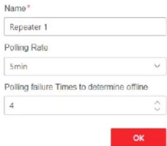
Figure 5-18. Repeater Sengs
- Click to enter the Manual Retransmission Rules page.
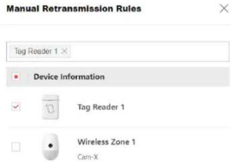
Figure 5-19. Manual Retransmission Rules
- Select devices in the list and click OK, and then the devices can be manually retransmied.
Add Keypad
You can set the parameters of the keypad that is enrolled to the AX PRO.
Steps
- Click Device to enter the page.
- Click + Add Device. In the Wireless Device area, click Manually Add.
- Select device type as Keypad, and set the device serial No. and model.
- Tap Next and set device.
- On the device list page, select a zone and click ✿ to enter the conguraon page.
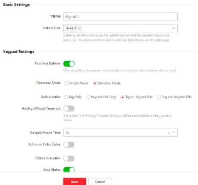
Figure 5-20. Keypad Sengs
Linked Area
Only enabled areas will be listed.
The newly added peripheral is linked to area 1 by default.
Funcon Buons
Aer disabling, re alarm, medical alarm and panic alarm buon will not work.
Arming Without Password
You can directly press the arm buon to arm without entering a password.
Keypad Awake Time
If the keypad has no acon within the set me, it will sleep automacally.
Acve on Entry Delay
When enabled, the keypad can be used during the entry delay.
Chime Indicaon
Enable chime.
Area Status
Display area status and alarm informaon in the keypad main page.
Remote Arm/Disarm Indicaon
Enable the remote arm/disarm LED indicaon.
Polling Rate
Sets the interval at which the system requires the device to return a report. If the device takes longer than the Polling failure Times to determine oine to reply, the system will report faults and the status of device will be shown as oine.
Backlight
Enable the keypad backlight. You can congregate the me schedule when the backlight is o.
Enable the alarm buzzer/buon buzzer.
Silent Panic Alarm/Silent Medical Alarm
Panic alarm/Medical alarm do not sound.
Text1/Text2
The text displayed on the main page when waking up. Customizable content.
1. Click Save.
Add Tag Reader
You can set the parameters of the tag reader.
Steps
- Click Device to enter the page.
- Click + Add Device. In the Wireless Device area, click Manually Add.
- Select device type as Tag Reader, and set the device serial No. and model.
- Tap Next and set device.
- On the device list page, select a zone and click 🔗 to enter the conguraon page.
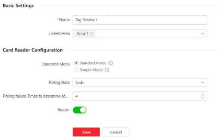
Figure 5-21. Tag Reader Sengs
Linked Area
Only enabled areas will be listed.
The newly added peripheral is linked to area 1 by default.
Operaon Mode
-Standard Mode: Area selecon and fault conrmaon are supported when arming or disarming. You should set the authorizaon method.
-Simple Mode: No Area selecon and fault conrmaon when swiping tag to arm or disarm.
Polling Rate
Sets the interval at which the system requires the device to return a report. If the device takes longer than the Polling failure Times to determine oine to reply, the system will report faults and the status of device will be shown as oine.
- Click Save.
Add Keyfob
You can add keyfob to the AX PRO and control the AX PRO via the keyfob. You can also edit the keyfob informaon or delete the keyfob from the AX PRO.
Steps
- Click Device to enter the page.
- Click + Add Device. In the Wireless Device area, click Manually Add.
- Select device type as Keyfob, and set the device serial No. and model.
- Tap Next and set device.
- On the device list page, select a zone and click ⚙ to enter the conguraon page.
Enable
Enable the keyfob or not.
Linked Area
Only enabled areas will be listed.
The newly added peripheral is linked to area 1 by default.
Buon Conguraon
Congure the funcons of single keys and key combinaons.
- Click Save.
Add Expander
Steps
- Click Device to enter the page.
- Click + Add Device. In the Wireless Device area, click Manually Add.
- Select device type as Expander, and set the device serial No. and model.
- Tap Next and set device.
- On the device list page, select a zone and click ⚙️ to enter the conguraon page.
Add Network Camera
You can add network cameras in the system.
Steps
- Click Device to enter the page.
- Click + Add Device. In the Network Camera/IP Device area, click Manually Add.
- Enter the network camera's IP address, and select the camera's protocol type, set the camera's user name and password.
- Click Next and set the device parameters.
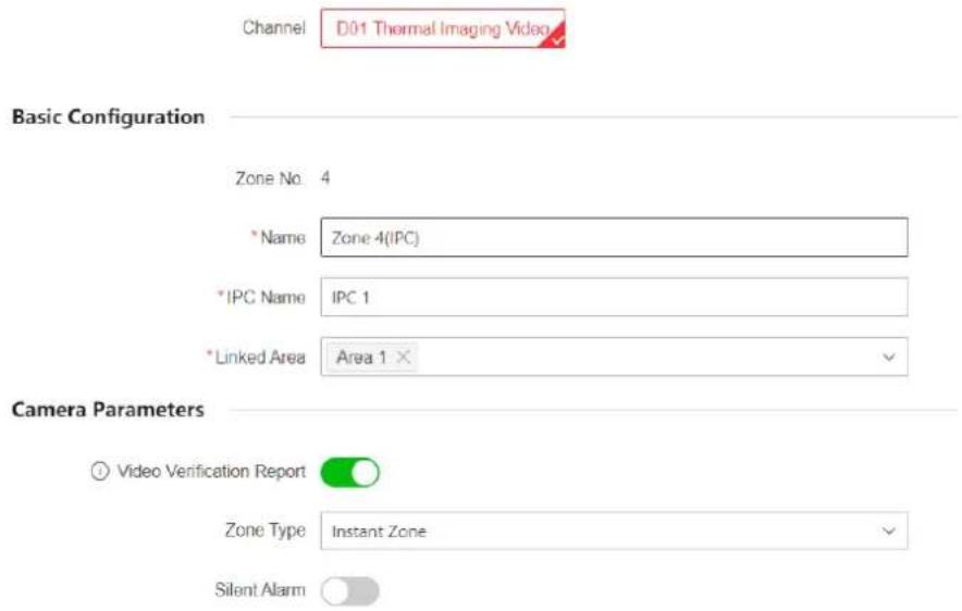
Figure 5-22. Network Camera Sengs
Video Vericaon Report
Enable to report alarm video. When the control panel uploads the alarm informaon, it will
return the picture and video address for you to view. The number of channels that can be enabled depends on the device model.
- Click to edit video parameters.
Stream Type
-Main Stream: Being used in recording and HD preview, it has a high resolution, code rate and picture quality.
-Sub-Stream: It is used to transmit network and preview pictures as a video streaming with features of lower resolution, bit rate and picture quality.
Bitrate Type
Select the Bitrate type as constant or variable.
Resoluon
Select the resolution of the video output.
Video Bitrate
The higher value corresponds to the higher video quality, but the beer bandwidth is required.
Post-record/Pre-record
Set the recording video me before and aer the alarm.
- Click Save.
5.3.3 System
System Sengs
You can view device informaon and congure device me.
Basic Informaon
Click Conguraon → System → System Sengs → Basic Sengs
You can edit the device name and view device informaon here.
Time Sengs
You can set the device me zone, synchronize device me, and set the DST me. The device supports me synchronizaon via Hik-Connect server.
Click Conguraon → System → System Sengs → Time Sengs to enter the page.
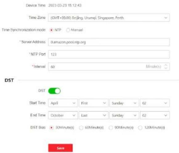
Figure 5-23. Time Sengs
Time Zone
Select a me zone from the drop-down list.
Time Synchronizaon mode
-NTP: Set the server address, NTP port and interval. The system will automatically synchronize the me with the server.
-Manual: Set the system me manually or click Sync. with Computer Time to synchronize the device me with the computer me.
DST
Set the start, end date and bias me for daylight saving me.
Click Save.
Panel Opons
Set the panel LED and voice prompt opons.
Click Conguraon → System → Panel Opon to enter the page.
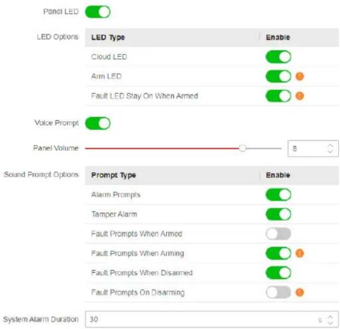
Figure 5-24. Panel Opon
Panel LED
Enable/Disable panel functional LED. You can also set the LED opons.
Voice Prompt
Enable/Disable sound prompt. Set the panel volume and sound prompt opons.
Alarm Prompts
Voice prompt of faults when an alarm is triggered.
Tamper Alarm
When a tamper alarm is triggered, a voice prompt will be triggered.
Fault Prompts When Armed
The system will make voice prompts when the control panel is armed.
Fault Prompts When Arming
The system will make voice prompts when arming.
Fault Prompts When Disarmed
The system will make voice prompts when the control panel is disarmed.
Fault Prompts When Disarming
The system will make voice prompts when disarming.
System Alarm Duraon
Set linked alarm voice prompt lasng me.
Click Save.
Service Conguraon
Congure the fault check, arming and regional cercaon.
Click Conguraon → System → Service → Service to enter the page.
Re-Arm on Restore
While enabled, the bypassed zone will back to arm if fault restored.
Audible Tamper Alarm
While enabled, the system will alert with buzzer for the tamper alarm. Regardless of whether it is enabled or not, the tamper alarm will be normally pushed to Cloud (for APP) and ARC.
Jamming Sensivity Sengs
The device will detect RF interference and push messages when the RF interference interferes with communicaon. You can adjust the detecon sensitivity.
Moon detectors include all PIR detectors.
-O: No automac restore.
-Immediate Aer Alarm: Moon detectors automacally restores immediately aer the alarm and reports to Cloud (for APP) and ARC.
-Aer Disarm: Moon detectors automacally restores aer disarming and reports to Cloud (for APP) and ARC.
Fault Checklist When Arming
The system will check if the device has the faults in the checklist during the arming process. The fault check here is only for the control panel in the normal status.
The system determines whether to check the faults listed on the page. The system will only check the fault that is selected.
| Fault Prompt Items | Type | Detected |
| > Battery Status | ||
| > Power Supply Availability | ||
| > Device Connection | ||
| > Server Connection | ||
| Lid Status | ||
| ARC Connection | ||
| Jamming Detection | ||
| Zone Triggered Fault |
Figure 5-25. Panel Fault Check
Baery Status
Baery Lost
If the opon is enabled, when baery is disconnected, the device will upload events.
Low Baery
If the opon is enabled, when baery is in low baery status, the device will upload
events.
Zone/Peripherals Low Baery
If the opon is enabled, when zone or peripherals' baery is in low baery status, the device will upload events.
Power Supply Availability
Panel Mains Power Lost
If the opon is enabled, an alarm will be triggered when the control panel main supply is disconnected.
To compliant the EN 50131-3, the report dealy duraon should be 10 s.
Peripheral Mains Power Lost
If the opon is enabled, when the peripheral's main power is lost, the alarm will be triggered.
Device Connecon
Zone/Peripherals Poll Failure/Oine
If the opon is enabled, when zone or peripherals' conncon is lost, the alarm will be triggered.
IP Camera Disconnecon
If the opon is enabled, when the network camera's conncon is lost, the alarm will be triggered.
Server Connecon
Ethernet Lost
If the opon is enabled, when the wired network is disconnected or with other faults, the alarm will be triggered.
Wi-Fi Lost
If the opon is enabled, when the Wi-Fi is disconnected or with other faults, the alarm will be triggered.
Cellular Lost
If the opon is enabled, when the cellular data network is disconnected or with other faults, the alarm will be triggered.
Lid Status
If the opon is enabled, an alarm will be triggered when the control panel or peripheral is lid open.
ARC Connecon
If the opon is enabled, an alarm will be triggered when the ARC (Alarm Receiving Center) conncon contains fault.
Jamming Detecon
If the opon is enabled, an alarm will be triggered when the control panel detectng jamming.
Zone Triggered Fault
If the opon is enabled, an alarm will be triggered when the control panel's zone triggering contains fault.
Panel Server Polling Interval
Set the me interval when the control panel's server is polling.
Delay of Server Connecon Failure
If the control panel server cannot connected for the delayed me duraon, conncon will failed.
Panel Fault Check
If the opon is enabled, an event will be reported aer the delayed me.
Power Saving Mode
While enabled, the main power supply is o, Wi-Fi enters low power consumption, 4G closes, tag reading fails. LED is o, and voice prompt is o.
PD6662
PD6662 is applicable to the UK market. If this funcon is enabled, the arming funcon and alarm logic of the control panel will change.
Enable PD6662 standard. Funcons that do not meet the standard will not take eect.
Communicaon Fault Sending Delay
The delay me while the ATP communicaon fault reports to ARC.
Panel Lockup Buon
All funcons of AX PRO will be frozen aer it is enabled. This funcon can only be enabled by users with installer permission.
Click Save.
Network Conguraon
Ethernet
You can set the device IP address and other network parameters.
Steps

Funcons varied depending on the model of the device.
- Click Conguraon → Network → Network Sengs → Ethernet to enter the page.
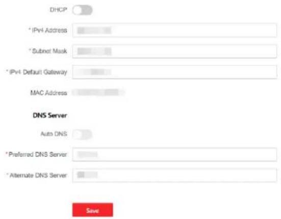
Figure 5-26. Ethernet
-
Set the parameters.
-
Automac Sengs: Enable DHCP.
-
Manual Setngs: Disabled DHCP and set other parameters.
-
Click Save.
Wi-Fi
Steps
- Click Conguraon → Network → Network Sengs → Wi-Fi to enter the page. You can view STA/AP Switch Status here.
-
Set the WLAN parameters.
-
Automac Sengs: Enable DHCP.
-
Manual Setngs: Disabled DHCP and set other parameters.
-
Click Save.
Cellular
Set the cellular network parameters if you insert a SIM card inside the device. By using the cellular network, the device can upload alarm nocaons to the alarm center.
Before You Start
Insert a SIM card into the device SIM card slot.
Steps
- Click Conguraon → Network → Network Sengs → Cellular to enter the page.
SIM Card Settings
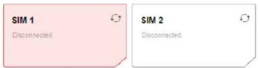
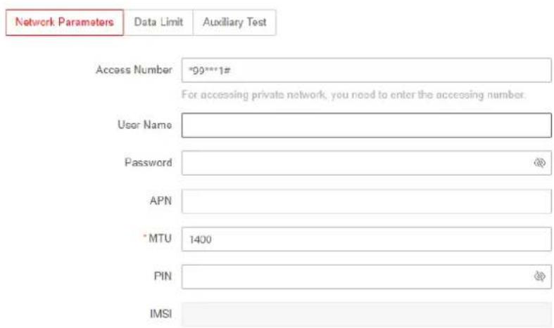
Figure 5-27. Cellular Data Network
- Enable the funcon.
- Set the cellular data network parameters.
Access Number
Enter the operator dialing number.

Note
Only the private network SIM card user needs to enter the dialing number.
User Name
Ask the network carrier and enter the user name.
Password
Ask the network carrier and enter the password.
APN
Ask the network carrier to get the APN informaon.
Data Limit
You can enable the funcon and set the data threshold every month.
Used Trac This Month
The used data will be accumulated and displayed in this text box.
Trac Threshold
If data usage is more than the congured threshold, an alarm will be triggered and uploaded to the alarm center and mobile client.
Network Connecon Test
Click Test to check network conncon status.
- Click Save.
Network Service
HTTP(S)
Click Conguraon → Network → Network Service → HTTP(S) to enter the page.
You can set HTTP port here.
NAT
Universal Plug and Play (UPnP™) is a networking architecture that provides compatibility among networking equipment, soware and other hardware devices. The UPnP protocol allows devices to connect seamlessly and to simplify the implementation of networks in the home and corporate environments.
Enable the UPnP funcon, and you don't need to conjure the port mapping for each port, and the device is connected to the Wide Area Network via the router.
- Click Conguraon → Network → Network Service → NAT to enter the page.
Port Mapping Mode
-Auto: Get the port number automacally.
-Manual: You need to enter external ports.
- Click Save.
Device Access
If you want to enroll the device to the mobile client for remote conguraon, you should set the mobile client enrollment parameters.
Before You Start
- Connect the device to the network via wired conncon, dial-up conncon, or Wi-Fi conncon.
- Set the device IP address, subnet mask, gateway and DNS server in the LAN.
Steps
- Click Conguraon → Network → Device Access → Cloud Service to enter the page.
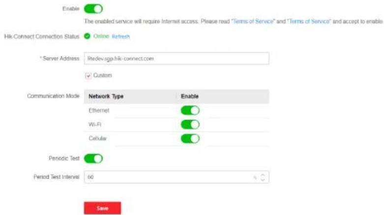
Figure 5-28. Device Access
- Drag the slider to enable the funcon.
iNote
By default, the device Hik-Connect service is enabled.
You can view the device status in the Hik-Connect server (www.hik-connect.com).
-
The server address is already displayed in the Server Address box, or you can check Custom to edit it.
-
Enable a network type according to the actual needs.
The conneccon mode order from high to low is: Ethernet, Wi-Fi, Cellular.
Ethernet
The system will select wired network.
Wi-Fi
The system will select Wi-Fi.
Cellular
The system will select cellular data network.
- Enable Periodic Test. Enter the periodic test interval.
Periodic Test
Aer enabling, you can set the me interval, seng how oen to send a test event to the ARC to ensure the conncon.
- Click Save.
Alarm Receiving Center
You can set the alarm receiving center's parameters and all alarms will be sent to the congured
alarm center.
Steps
- Click Conguraon → Alarm Communicaon → Alarm Receiving Center to enter the page.
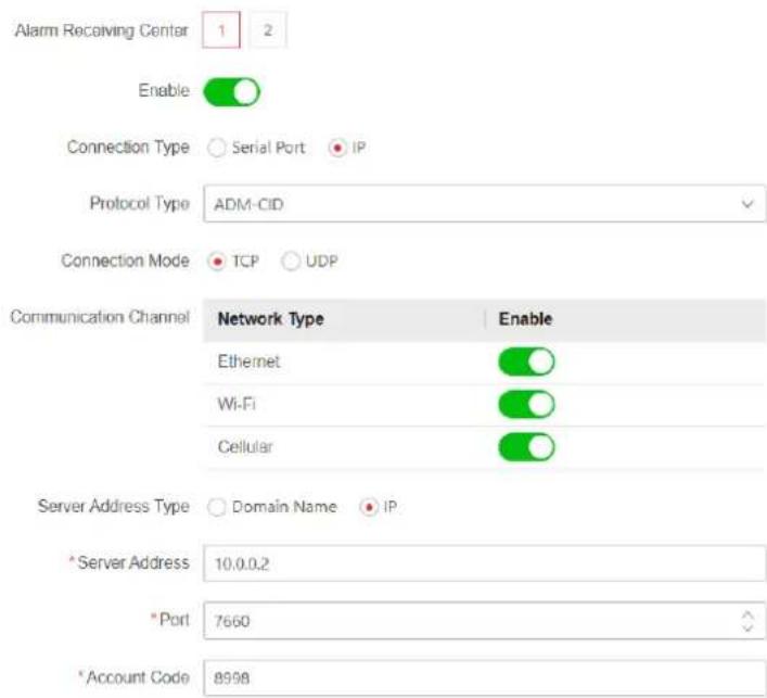
Figure 5-29. Alarm Receiving Center
- Select the Alarm Receiving Center as 1 or 2 for conguraon, and slide the slider to enable the selected alarm receiving center.
iNote
Only if the alarm receiving center 1(ARC1) is enabled, you can set the alarm receiver center 2 as the backup channel and edit the channel parameters.
- Enable the funcon and select a conncon type. Here takes selecng IP as an example.
- Select the Protocol Type as ADM-CID, ISUP, SIA-DCS, *SIA-DCS, *ADM-CID, CSV-IP, FSK Module or RDC Module to set uploading mode.

Note
Standard DC-09 Protocol
ADM-CID: The data presenng method of DC-09 is CID, which is not encrypted and only for uploading alarm report.
*ADM-CID: The data presenng method of DC-09 is CID, which is encrypted and only for uploading alarm report.
SIA-DCS: The data presenng method of DC-09 is DCS (also called SIA protocol), which is not encrypted and only for uploading alarm report.
*SIA-DCS: The data presenng method of DC-09 is DCS (also called SIA protocol), which is encrypted and only for uploading alarm report.
- ADM-CID or SIA-DCS: You should select the Address Type as IP or Domain name, and set the server address, port number, account code, impulse counting me, aempts, polling rate.
– ISUP, CSV-IP, FSK and RDC: You do not need to set the protocol parameters. - *SIA-DCS or *ADM-CID You should select the Address Type as IP or Domain name, and set the server address, port number, account code, impulse counting me, aempts, encrypon arithmec, password length and secret key.
Communicaon Channel
The conncon mode order from high to low is: Ethernet, Wi-Fi, Cellular.
Ethernet
The system will select wired network.
Wi-Fi
The system will select Wi-Fi.
Cellular
The system will select cellular data network.
Server Address Type
Select server address type as Domain Name or IP. And set she server address/domain name and port.
Account Code
Input the assigned account provided by the ARC.
Polling Opon
Set the polling rate with the range from 10 to 3888000 seconds. The system will report fault if the me is over the limit. The status of device will be shown as oine.
Periodic Test
Aer enabling, you can set the me interval, seng how oen to send a test event to the ARC to ensure the conncon.
Retry Timeout Period
Aer the selected me, the system will retry to transmit.
Aempts
Set the number of retry aempts.
Companies
Select the support company as None, Hungary-Mul Alarm Receiving Company or French Alarm Receiving Company.
PIRCAM Picture Upload Mode
For details, see 5.1 Set-up with Hik-Partner Pro.
HTTP Data Transmission
Enter the server address and tap test to test the IP. The triggered alarm informaon will be sent to the address.
Push Nocaon
Enable the push nocaon type, the enabled event will be sent to the ARC.
Alarm Event
Zone Alarm
The device will push nocaons when the zone alarm (on web client, soware client or mobile client) is triggered or the zone peripherals alarm is triggered or restored.
Panel Lid Opened
The device will push nocaons when lid opened alarm of the control panel is triggered or restored.
Peripherals Lid Opened
The device will push nocaons when lid opened alarm of any peripheral is triggered or restored.
Keypad/Keyfob/APP Panic Alarm
The device will push nocaons when panic alarm on keypads/keyfobs/APP is triggered or restored.
Keypad/Keyfob Medical Alarm
The device will push nocaons when medical alarm on keypads or keyfobs is triggered.
Keypad Fire Alarm
The device will push nocaons when re alarm on keypads is triggered or a user presses the re alarm key on the keypad.
Camera Events
The device will push nocaons when alarm is triggered in network cameras(using HIKVISION protocol).
PIRCAM Gif
The video and pictures generated by PIR cameras will be uploaded to the alarm receiving center.
Video Clips
The video and pictures generated by network cameras will be uploaded to the alarm
receiving center.
Fault Event
Panel Status (Power and Baery)
The device will push nocaons when the control panel power/baery status is changed.
Panel Status (Communicaon)
The device will push nocaons when the control panel communicaon status is changed.
Zone Status
The device will push nocaons when any zone status is changed.
Peripherals Status
The device will push nocaons when any peripheral status is changed.
Operaon Event
System Operaon
The device will push nocaons when the user operate the control panel.
System Event
Panel Upgrade
The device will push nocaons when the control panel is upgraded.
GMT
Enable the Greenwich Mean Time.
7. Click Save.
Use PIRCAM to Upload Pictures or Videos
You can enable the PIRCAM funcon to upload pictures or videos.
1. Upload Pictures
You can choose to upload 1 to 20 pictures.
(1) Click Conguraon → Alarm Communicaon → Alarm Receiving Center to enter the page.
(2) Slide the slider to enable the selected alarm receiving center.
(3) Select the Protocol Type as SIA-DCS.
(4) Select the Companies as French Alarm Receiving Company.
(5) Select to upload videos or pictures
(6) Click Save.
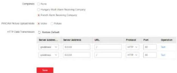
Figure 5-30. Upload Video and Picture
- Congure SMTP parameters:
(1) Click Conguraon → Alarm Communicaon → Nocaon by Email.
(2) Slide to enable the funcon and set corresponding parameters. For details, see Nocaon by Email. Click Save.
- Congure FTP parameters:
(1) Click Conguraon → Alarm Communicaon → FTP to enter the page.
(2) Slide to enable FTP and set corresponding parameters. For details, see FTP. Click Save.
- Upload Videos
In this condition, when the PIRCAM is set to catch more than two pictures, videos will be uploaded.
(1) Click Conguraon → Alarm Communicaon → Alarm Receiving Center to enter the page.
(2) Slide the slider to enable the selected alarm receiver center.
(3) Select the Protocol Type as SIA-DCS.
(4) Click Save.
(5) Congure SMTP or FTP parameters as same as Upload Photos.
Push App
Send the alarm nocaons to the App.
Steps
-
Click Conguraon → User Management.
-
Select a user and set the cloud push type.
The system will send the select alarm nocaons to the App of the edited user account.
Push Phone and SMS
Send the alarm nocaons to phones.
Steps
-
Click Conguraon → Alarm Communicaon → Push Phone and SMS.
-
Click Import New Audio.
The system will send the alarm nocaons through voice call to the reserved phone number.

Note
Do not congregate the phone number to the SIM card inserted in the device itself, otherwise abnormal charges will occur and the user will have to bear them.
- Click Edit SMS and edit the message content.
The system will send the message to the reserved phone number.
Nocaon by Email
You can send the alarm video or event to the congured email.
Steps
- Click Conguraon → Alarm Communicaon → Nocaon by Email to enter the page.
- Select and enable Email 1.
- Slide the Enable block.
- Enter the sender's informaon.

Note
- It is recommended to use Gmail and Hotmail for sending mails.
-
Only if the zone is linked with a network camera, the alarm email will be aached with alarm video.
-
Set the SMTP server address and port.
- Set the encrypon type.
- Enable Server Authencaon. When the funcon is enabled, when the server ask an authencaon, the user name and password will be checked.
- Enter the receiver's informaon.
- Click Receiver Address Test and make sure the address is correct.
- Click Save.
- Oponal: Congure Email 2 in the same order. You can choose whether to set email 2 as a backup mailbox.

Note
Video and picture reviews will be sent to both mailboxes. If Email 2 is set as a backup mailbox, the system will push emails to Email 2 only if Email 1 fails to receive.
FTP
You can congregate the FTP server to save alarm video.
Steps
- Click Conguraon → Alarm Communicaon → FTP to enter the page.
- Congure the FTP parameters.
FTP Type
Set the FTP type as main used or alternated.
Protocol Type
Enable FTP funcon and FTP and SFTP are selectable. The les uploading is encrypted by using SFTP protocol.
Server Address and Port
Enable FTP funcon and select the server type.
Set the FTP server address and corresponding port.
Enable Anonymity
The FTP user should have the permission to upload pictures. If the FTP server supports picture uploading by anonymous users, you can enable Anonymity to hide your device informaon during uploading. Otherwise, you should enter user informaon.
Directory Structure
The saving path of snapshots in the FTP server.
3. Click Save.
Intercom Service
You can congregate the Intercom service for an intercom sounder.
Before You Start
You should enroll an intercom sounder rst.
Only one sounder can be set as the intercom sounder.
Steps
- Click Conguraon → Alarm Communicaon → Intercom Service to enter the page.
- Slide to enable the funcon.
- Set intercom type.
SIP
The control panel will use ARC and SIP server.
IP Receiver Pro
The control panel supports intercom of cloud service and ISUP protocol.
ISUP
The control panel uses the ISUP protocol through the Hik-Central APP.
4. Set parameters.
Alarm Verify Priority
Select picture or audio rst.
- Select a sounder and click Save.
5.3.4 Maintenance and Security
Maintenance
Restart
Click Maintenance and Security → Maintenance → Restart to enter the page.
Click Restart to restart the device.
Control Panel Upgrade
- Click Maintenance and Security → Maintenance → Control Panel Upgrade to enter the page.
- Click to nd the rmware le with the name digicap.dav.
- Click Upgrade to complete.
Detector & Peripheral Upgrade
- Click Maintenance and Security → Maintenance → Detector & Peripheral Upgrade to enter the page.
- Select the Upgrade Type and the Peripheral.
- Click to nd the rmware upgrade le.
- Click Upgrade to complete.

Both of the users and conguraon informaon will be retained aer upgrade nished.
Backup and Reset Sengs
You can restore default sengs, import conguraon le, or export device parameters.
Click Maintenance and Security → Maintenance → Backup and Reset to enter the page.
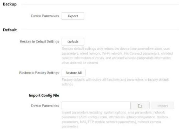
Figure 5-31. Backup and Reset
Export Conguraon File
Click Export to export the device conguraon parameters to the PC.
Restore to Default Sengs
Click Default will restore all parameters except for device me zone informaon, user parameters, wired network, Wi-Fi network, HC informaon detector informaon, detector informaon enrolled in the zone and enrolled wireless peripheral informaon.
Restore to Factory Sengs
Click Restore All to restore all parameters to the factory sengs.
Import Conguraon File
Click to select conguraon le from the PC and click Import to import conguraon parameters to the device.
Log
You can search the log on the device.
Click Maintenance and Security → Maintenance → Log to enter the page.
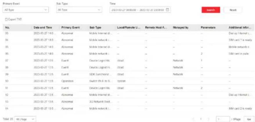
Figure 5-32. Log
Select a primary event and a sub type from the drop-down list, set the log start me and end me and click Search. All found log informaon will be displayed in the list.
You can also click Reset to reset all search conditions.
Security Audit Log
You can add the Security Audit Server to the system. The device will upload web logs to the server.
Steps
- Click Maintenance and Security → Maintenance → Security Audit Log to enter the page.
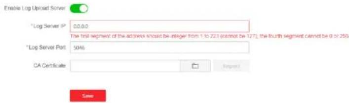
Figure 5-33. Security Audit Log
- Slide Enable Log Upload Server.
- Enter log server IP and port.
- Click to select a cercate.
iNote
Formats include ca.crt, ca-chan.crt, private.txt are allowed.
- Click Import.
- Click Save.
Walk Test
The AX PRO supports walk test funcon.
Steps
- Enter Maintenance and Security → Maintenance → Walk Test to enable the funcon.
iNote
Only when all the detectors are without fault, you can enter the mode TEST mode.
- Slide Enable.
- Trigger the detector in each zone.
- Click Refresh and check test results.
Device Debugging
You can export debugging le to the PC.
Steps
- Click Maintenance and Security → Maintenance → Export File to enter the page.
- Slide to enable funcons.
SSH
Enable or disable SSH (Secure Shell) according to your actual needs.
Debugging Log
Enable the funcon and click Export to export serial logs.
Tamper Alarm on HPP Login
Aer this funcon is enabled, the device lid opened alarm (tamper alarm) takes eect when installer login. (By default, the lid opened alarm (tamper alarm) does not take eect when the
installer login.)
Event Log for Cellular Service
If enabled, you can get the log when using the cellular service.
Capture Packet
You can set packet capture parameters. Set the packet capture duraon, packet capture API, and Iter condion. Click Start Capturing Packet and the result will display.
3. Click Save.
Security
Enable or disable SSH (Secure Shell) according to your actual needs.
Click System → System Security → SSH Sengs to enter the SSH Sengs page and you can enable or disable the SSH funcon.
User Lockout Aempts
The device will be locked 90 s aer 3 failed credenal aempts (can be set in Retry Times Before Auto-Lock) in a minute.
You can view the locked user or unlock a user and set the user locked duraon.
iNote
To compliant the EN requirement, the system will only record the same log 3 mes connuously.
Steps
- Click Maintenance and Security → Maintenance → User Lockout Aempts to enter the page.
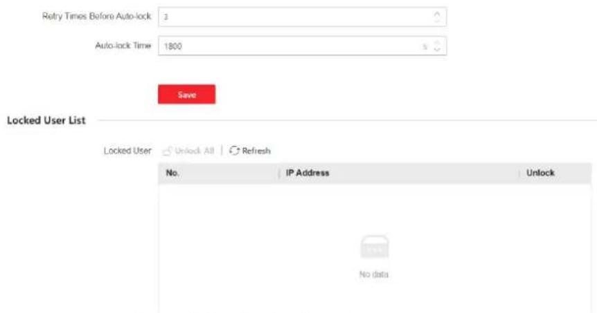
Figure 5-34. User Lockout Aempts
- Set parameters.
Retry Times Before Auto-Lock
If the user connuously input the incorrect password for more than the congured mes, the account will be locked.

Note
The administrator has two more aempts than the congured value.
Auto-lock Time
Set the locking duraon when the account is locked.

Note
The available locking duraon is 5s to 1800s.
- Click 🔒 to unlock the account or click Unlock All to unlock all locked users in the list.
- Click Save.
Module Lock Sengs
Set the module locking parameters, including the Retry Times before Auto-Lock, and locked duraon. The module will be locked for the programmed me duraon, once the module authencaon has failed for the amount of congured mes.
Steps
-
Click Maintenance and Security → Maintenance → Module Locking Sengs to enter the page.
-
Select a module from the list, and click

Name
Keypad 1
Device Type
Keypad
Retry Times Before Auto-lock


Auto-lock Time


Cancel
Figure 5-35. Module Locking Sengs
- Set the following parameters of the selected module.
Retry Times before Auto-Lock
If a user connuously tries to authencaon a password for more than the congured aempts permied, the keypad will be locked for the programmed duraon.
Auto-lock Time
Set the locking duraon when the keypad is locked. Aer the congured duraon, the keypad will be unlocked.
4. Click Save.
5.4 Report to ARC (Alarm Receiving Center)
AX PRO wireless control panel is designed with transceiver built in following the guidance of EN 50131-10 and EN 50136-2. Category DP2 is provided with primary network interface of LAN/WiFi and secondary network interface of GPRS or 3G/4G LTE. ATS (Alarm Transmission system) is designed to always use LAN/Wi-Fi network interface when available to save mobile data usage. The secondary network interface provides resilience and reliability during mains power failure.
Setup ATS in Transceiver of Receiving Center
Steps:
-
Login to the web client of the alarm receiver.
-
Click Conguraon→ IP Recepon, and create a receiving server as shown below.
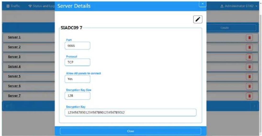
Figure 5-36. IP Recepon
- Click Alarms and Accounts→Accounts Management, and assign an account for the panel as show below.
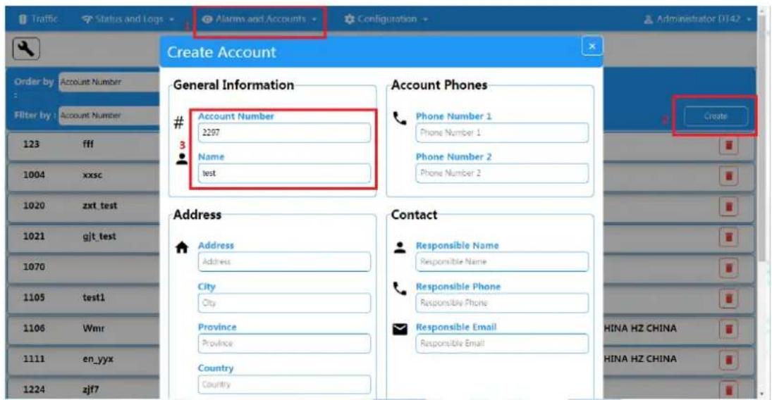
Figure 5-37. Account Management
Setup ATS in Transceiver of the Panel Steps:
- Login using installer account from local web client.
- Click Communicaton→Alarm Receiving Center (ARC), and enable Alarm Receiving Center 1.
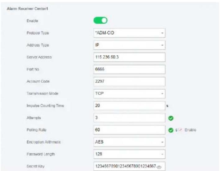
Figure 5-38. ARC1
● = Protocol Setting =
Protocol Type
— ADM-CID
— SIA-DCS
— *ADM-CID
— *SIA-DCS
Select token supported by the receiver in the ARC. Choose the token with “*” mark to
improve the communication security.
● = Server Setting =
■ Address Type
— IP
— Domain Name
■ Server Address / Domain Name
■ Port No.
Input IP address or domain name by which the transceiver of receiving center could be reached. Input port number of the server provided by the ARC
● = Account Setting =
Account Code
Input the assigned account provided by the ARC.
● = SIA DC-09 Protocol Setting =
■ Transmission Mode
— TCP
— UDP
Both TCP and UDP are supported for transmission. UDP is recommended by the SIA DC-09 standard.
■ Connection Setting
- Impulse Counting Time / Retry Timeout Period
Setup the timeout period waiting for receiver to respond. Re-transmission will be arranged if the transceiver of receiving center is timeout.
- Attempts
Setup the maximum number that re-transmission will be tried.
○ Polling Rate
Setup the interval between 2 live polling if enable is checked.
■ Encryption Setting
○ Encryption Arithmetic
— AES
- Password Length
— 128
— 192
— 256
Secret Key
Setup the encryption key length and input the key provided by the ARC.
Signaling Test
Acvate a panic alarm from the control panel.
Login to Receiver. Click Trac to review all the messages received.
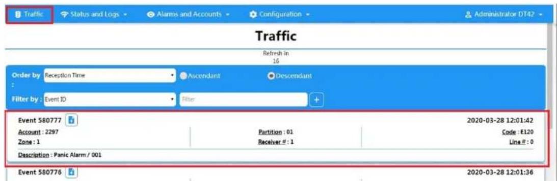
Figure 5-39. Trac
Chapter 6 General Operaons
6.1 Arming
You can use keypad, keyfob, Tag, client soware, mobile client to arm your system.
Aer the arming command is sending to AX PRO, the system will check the detector status. If the detector is in fault, you will need to choose whether to arm the system with fault.
While the system is armed, the AX PRO will prompt the result in 5s, and upload the arming report.
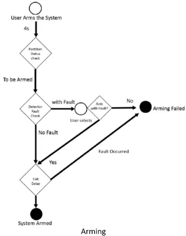
flowchart
graph TD
    A["User Arms the System"] -->|4s| B{Partition Status check}
    B -->|To be Armed| C{Detector Fault Check}
    C -->|No Fault| D{Exit Delay}
    C -->|with Fault| E{Arm with Fault?}
    E -->|No| F["Arming Failed"]
    E -->|Yes| D
    F --> G["System Armed"]
    D --> H["Fault Occurred"]
    H --> E
Access level of Arming
The user in level 2 or 3 has the permission to arm or partly arm the system.
Arming Indicaon
The arming/disarming indicator keeps solid blue for 5s.
Reason of Arming Failure
- Intrusion detector triggered (excepts the detector on the exit route).
- Panic alarm device triggered.
- Tampering alarm occurred.
-
Communicaon excepon
-
Main power supply exceedon
- Backup baery excepon
- Alarm receiving fault
- Sounder fault
- Low baery of the keyfob
- Others
Arming with Fault
While the arming is stopped with fault, user in level 2 has the permission to arm the system with fault (forced arming).
Forced arming only takes eect on the current arming operaon.
The forced arming operaon will be record in the event log.
6.2 Disarming
You can disarm the system with keypad, keyfob, tag, client soware, or mobile client.
Disarming Indicaon
The arming/disarming indicator ashes 30s while the user successfully disarm the system through the entry/exit route.
The system will report the disarming result aer the operaon completed.
Entry Delay Duraon
Ensure that mer is no longer than 45 seconds in order to comply with EN50131-1.
Early Alarm
If the rst instant zone is triggered when the AX PRO is in the status of entry delay, the AX PRO then enters the early alarm mode.
The early alarm duraon can be set (> 30s).
The AX PRO will reports the alarm only if the alarm event lasts over the duraon of early alarm with the addition of entry delay.
6.3 SMS Control
You can control the security system with SMS, and the command is shown below.
SMS format for Arming/disarming/silencing alarm:
$$ {\text { Command } } + {\text { Operaon Type } } + {\text { Target } } $$
Command: 2 digits, 00- Disarming, 01- Away arming, 02- Stay arming, 03- Silencing alarm
Operaon type: 1- Area Operaon
Target: No more than 3 digits, 0-Operaon for all areas, 1-Operaon for area 1(zone1), and the rest can be deduced by the analogy.
A. Trouble Shoong
A.1 Communicaon Fault
A.1.1 IP Conict
Fault Descripon:
IP that the panel automacally acquired or set is same as other devices, resulting in IP conicts.
Soluon:
Search the current available IP through ping. Change the IP address and log in again.
A.1.2 Web Page is Not Accessible
Fault Descripon:
Use browser to access web pages and display Inaccessible.
Soluons:
-
Check whether the network cable is loose and the panel network is abnormal.
-
The panel port has been modified. Please add a port to the web address for further access.
A.1.3 Hik-Connect is Oine
Fault Descripon:
The web page shows that the Hik-Connect is oine.
Soluon:
Network conguraon of the panel is error, unable to access extranet.
A.1.4 Network Camera Drops o Frequently
Fault Descripon:
System reports mulple event logs of IPC disconncon and conncon.
Soluon:
Check whether the network communicaon or camera live view is proper.
A.1.5 Failed to Add Device on APP
Fault Descripon:
When using APP to add devices, it is prompted that the device fails to be added, the device could not be found, etc.
Soluon:
Check the web page: whether the Hik-Connect is oine.
A.1.6 Alarm Informaon is Not Reported to APP/4200/Alarm Center
Fault Descripon:
Aer the alarm is triggered, the app/4200/ alarm center does not receive the alarm message.
Soluon:
"Message push" - "alarm and tamper-proof noce" is not enabled. You should enable "alarm and tamper-proof noce".
A.2 Mutual Exclusion of Funcons
A.2.1 Unable to Enter Registraon Mode
Fault Descripon:
Click the panel funcon key, and prompt key invalid.
Soluon:
The panel is in "Hotspot" mode. Switch the panel to "staon" mode, and then try to enter the registraon mode again.
A.3 Zone Fault
A.3.1 Zone is Oine
Fault Descripon:
View status of zones which displays oine.
Soluon:
Check whether the detector reports undervoltage. Replace the detector baery
A.3.2 Zone Tamper-proof
Fault Descripon:
View status of zones which displays tamper-proof.
Soluon:
Make tamper-proof buon of the detector holden.
A.3.3 Zone Triggered/Fault
Fault Descripon:
View status of zones which displays triggered/fault.
Soluon:
Reset the detector.
A.4 Problems While Arming
A.4.1 Failure in Arming (When the forced arming is not enabled)
Fault Descripon:
When the panel is arming, prompt arming fails.
Soluon:
The panel does not enable "forced arming", and when there is a fault in the zone, the arming will fail. Please turn on the "forced arming" enable, or restore the zone to the normal status.
A.5 Operaonal Failure
A.5.1 Failed to Enter the Test Mode
Fault Descripon:
Failed to enable test mode, prompting "A fault in the zone".
Soluon:
Zone status, alarm status or zone power is abnormal.
A.5.2 The Silence Alarm Operaon on the Panel Does Not Produce the Silence Alarm Report
Fault Descripon:
The alarm clearing operaon on the panel does not produce the alarm clearing report.
Soluon:
In the absence of alarm, no report will be uploaded for arm clearing.
A.6 Mail Delivery Failure
A.6.1 Failed to Send Test Mail
Fault Descripon:
when congregate the mail informaon, click "test inbox" and prompt test fails.
Soluon:
Wrong conguraon of mailbox parameters. Please edit the mailbox conguraon informaon, as shown in table 1/1.
A.6.2 Failed to Send Mail during Use
Fault Descripon:
Check the panel excepon log. There is "mail sending failure".
Soluon:
The mailbox server has restricted access. Please log in to the mailbox to see if the mailbox is locked.
A.6.3 Failed to Send Mails to Gmail
Fault Descripon:
The receiver's mailbox is Gmail. Click "Test Inbox" and prompt test fails.
- Google prevents users from accessing Gmail using apps/devices that do not meet their security standards.
Soluon:
Log in to the website (hps://www.google.com/sengs/security/lesssecureapps), and "start using access of applicaon not safe enough". The device can send mails normally.
- Gmail does not remove CAPTCHA authencaon.
Soluon: Click the link below, and then click "connue"
(hps://accounts.google.com/b/0/displayunlockcaptcha).
A.6.4 Failed to Send Mails to QQ or Foxmail
Fault Descripon:
The receiver's mailbox is QQ or foxmail. Click "Test Inbox" and prompt test fails.
- Wrong QQ account or password.
Soluon:
the password required for QQ account login is not the password used for normal login. The specific path is: Enter the email account → device → account → to generate the authorizaon code, and use the authorizaon code as the login password.
- SMTP login permission is needed to open.
A.6.5 Failed to Send Mails to Yahoo
Fault Descripon:
The receiver's mailbox is yahoo. Click "test inbox" and prompt test fails.
- The security level of mailbox is too high.
Soluon:
Go to your mail account and turn on "less secure sign-in".
A.6.6 Mail Conguraon
Table A-1 Mail Conguraon
| Mail Type | Mail Server | SMTP Port | Protocols Supported |
| Gmail | smtp.gmail.com | 587 | TLS/STARTTLS (TLS) |
| Outlook | smtp.oce365.com | 587 | STARTTLS (TLS) |
| Hotmail | smtp.oce365.com | 587 | STARTTLS (TLS) |
| smtp.qq.com | 587 | STARTTLS (TLSv1.2) | |
| Yahoo | smtp.mail.yahoo.com | 587 | STARTTLS (TLSv1.2) |
| 126 | smtp.126.com | 465 | SSL/TLS |
| Sina | smtp.sina.com | 25/465/587 | SSL/TLS/STARTTLS (SSL/TLS) |

Note
About mail conguraon:
- SMTP portDefault to use port 25 without encrypon, or using port 465 if SSL/TLS is used. Port 587 is mainly used for STARTTLS protocol mode.
The STARTTLS protocol mode that is usually used by default when selecng TLS. - User nameUser name of Outlook and Hotmail require full names, and other email require a prex before @.
B. Input Types
Table B-1 Input Types
| Input Types | Operaons |
| Instant Zone | The system will immediately alarm when it detects triggering event aer system armed.Audible Response Trigger the system sound and sounder.Voice Prompt: Zone X alarm. |
| Perimeter Zone | The system will immediately alarm when it detects triggering event aer system armed.Audible Response: Trigger the system sound and sounder.There is a congorable interval between alarm and sounder output, which allows you to check the alarm and cancel the sounder output during the interval.Voice Prompt: Zone X perimeter alarm. |
| Delayed Zone | The system provides you me to leave through or enter the area without alarm.Audible Response: Trigger the system sound and sounder.Voice Prompt: Zone X alarm. |
| Follow Zone | The zone acts as delayed zone when it detects triggering event during system Entry Delay, while it acts as instant zone otherwise.Audible Response: Trigger the system sound and sounder.Voice Prompt: Zone X follow alarm. |
| 24H Silence Zone | The zone acvates all the me without any sound/sounder output when alarm occurs.Audible Response: No system sound (voice prompt or sounder). |
| Panic Zone | The zone acvates all the me.Audible Response: Trigger the system sound and sounder.Voice Prompt: Zone X panic alarm. |
| Fire Zone | The zone acvates all the me with sound/sounder output when alarm occurs.Audible Response: Trigger the system sound and sounder. Voice Prompt: Zone X re alarm. |
| Gas Zone | The zone acvates all the me with sound/sounder output when alarm occurs. Audible Response: Trigger the system sound and sounder. Voice Prompt: Zone X gas alarm. |
| Medical Zone | The zone acvates all the me with beep conrmaon when alarm occurs. Audible Response: Trigger the system sound and sounder. Voice Prompt: Zone X medical alarm. |
| Timeout Zone | The zone acvates all the me. The zone type is used to monitor and report the "ACTIVE" status of a zone, but it will only report and alarm this status aer the programmed me has expired (1 to 599) seconds. |
| Disabled Zone | Alarms will not be acvated when the zone is triggered or tampered. Audible Response: No system sound (voice prompt or sounder). |
| Virtual Zone (Keypad/Keyfob) | The system will immediately alarm when it detects triggering event aer system armed. Audible Response: Trigger the system sound and sounder. Voice Prompt: Buzzer beeps. |
| Tamper Alarm | The system will immediately alarm when it detects triggering event aer system armed. Audible Response: Trigger the system sound and sounder. Voice Prompt: Zone X tampered. |
| Link | Trigger the linked device when event occurs. e.g. The output expander linked relays will be enabled when the AX PRO is armed. |
| Arm | When armed: Voice prompt for fault. You can handle the fault according to the voice prompt. • System sound for arming with Tag or keyfob. • Voice prompt for fault. You can handle the fault according to the voice prompt. |
Fault event displays on client. You can handle the fault via client soware or mobile client.
Voice Prompt: Armed/Arming failed.
C. Output Types
Table C-1 Output Types
| Output Types | Acve | Restore |
| Arming | Arm the AX PRO | Aer the congured output delay |
| Disarming | Disarm the AX PRO | Aer the congured output delay |
| Alarm | When alarm event occurs. The alarm output will be acvated aer the congured exit/enter delay. | Aer the congured output delay, disarm the AX PRO or silence alarm |
| Zone Linkage | When alarm event occurs, the linked relay will output alarm signal. | Aer the congured output duraon |
| Manual Operaon | Enable relays manually | Over the triggering me or disable the relays manually |
D. Event Types
Table D-1 Event Types
| Event Types | Custom | Default 1(clientsowarenocaon) | Default 2(alarmreceivingcenter 1/2) | Default 3(mobileclient) | Default 4(telephone) |
| Alarm andTamper | ×/ | ||||
| Life SafetyEvent | ×/ | ||||
| System Status | ×/ | × | × | × | |
| PanelManagement | ×/ | × | × | × |
E. Access Levels
| Level | Descripon |
| 1 | Access by any person; for example the general public. |
| 2 | User access by an operator and administrator; for example customers (systems users). |
| 3 | User access by an installer; for example an alarm company professional. |
Table E-1 Permission of the Access Level
| Funcon | Permission | ||
| 1 | 2 | 3 | |
| Arming | No | Yes | Yes |
| Disarming | No | Yes | Yes |
| Restoring/Clearing Alarm | No | Yes | Yes |
| Entering Walk Test Mode | No | Yes | Yes |
| Bypass(zone)/Disabling/Force Arming | No | Yes | Yes |
| Adding/Changing Vericaon Code | No | Yes^d | Yes^d |
| Adding/Eding Level 2 User and Vericaon Code | No | Yes | Yes |
| Adding/Eding Conguraon Data | No | No | Yes |
| Replacing soware and rmware | No | No | No |
iNote
^a By the condition of being accredited by user in level 2.
^b By the condition of being accredited by user in level 2 and level 3.
^d Users can only edit their own user code.
- The user level 2 can assign the login permission of the controller to the user level 3 in the sengs page.
- The user level 2 should assign permissions to the user level 3 if the user level 3 wants to login the controller remotely.
-
When the controller is bypassed, the user level 3 can login the controller without the permission assignment of the user level 2.
-
When the controller is bypassed, the user level 3 can login the controller without the permission assignment of the user level 2.
- The user level 4 can login the controller only when the user level 2 or level 3 has assigned permissions to the user level 4.
F. Signalling
Detecon of ATP/ATS Faults
ATP (Alarm Transmission Path) faults will be detected when network interface of the control panel disconnected or the transmission path to the transceiver of receiving center located in ARC blocked somewhere in between. An ATS (Alarm Transmission System) fault will be reported when ATP faults are detected on both transmission paths.
ATP restore will be detected as soon as network interface connected and the transmission path to the transceiver of receiving center restored. ATS restore will be reported when ATP restore of any transmission path is detected.
The ming performance of detectng ATP faults and restores shows in the table below.
| TN | Maximum ming of detecon | |
| Primary ATP failure/restore | LAN/WiFi | 10 min |
| Secondary ATP failure/restore | GPRS | 60 min |
| 3G/4G LTE | 20 min (when primary ATP failed) |
Signalling will be always transmied from primary ATP when it is operational. Otherwise it will be automacally switched to secondary transmission path that is operational at the moment. Both primary and secondary ATP fault and restore events will be reported to ARC when there is an ATP le to work. They will also be recorded to mandatory log memory with capacity of 1000 records allocated in non-volale ash memory storage, as well as the ATS fault record. The detail of reports and log records are listed in the table below.
| Event code when signalling | Event log descripon | |
| Primary ATP failure/restore | E351/R351 | LAN Path Failed/LAN Path Recovery |
| Secondary ATP failure/restore | E352/R352 | Mobile Net Path Failed/Mobile Net Path Recovery |
| ATS failure/restore | N/A | ATS Failed |
| Primary network interface failure/restore | E351/R351 | LAN Path Failed/LAN Path Recovery |
| Secondary network interface failure/restore | E352/R352 | Mobile Net Path Failed/Mobile Net Path Recovery |
ATS Category
The ATS category of AXPRO is DP2. While the alarm receiving center is enabled. The control panel will upload alarm report to the receiver center via the main path (LAN or Wi-Fi) or the back-up path (3G/4G). If the control panel is properly connected to the LAN or Wi-Fi, the main path is selected as the transmission path. If the main path conncon is failed, the path will be switched to 3G/4G. And if the main path conncon is restored, the path will be switched back to LAN or Wi-Fi. The control panel checks the conncon status connuously, and generates logs transmission fault for any of the path. While both of the paths are invalid, the control panel determines ATS fault.
G. SIA and CID Code

Note
The code is for transming from the security control panel to ARC via DC09 protocol.
Read the table below to obtain the events corresponding to the CID code.
You can scan the QR code and download the CID table separately.

| Control Panel AX PRO | ||||
| Event Descripon | Event Type | CID Code/STD Code | SIA Code | HIK Code |
| Lid Opened | Alarm | 1137 | TA | 1137 |
| Lid Closed | Alarm | 3137 | TR | 3137 |
| AC Power Down | Status | 1301 | AT | 1301 |
| AC Power Restored | Status | 3301 | AR | 3301 |
| Baery Low | Status | 1302 | YT | 1302 |
| Baery Voltage Restored | Status | 3302 | YR | 3302 |
| Baery Fault | Status | 1311 | YT | 1310 |
| Baery Fault Restored | Status | 3311 | YR | 3310 |
| Baery Disconnected | Status | 1311 | YM | 1311 |
| Baery Reconnected | Status | 3311 | YR | 3311 |
| Main Signalling Path ATP Fault | Status | 1351 | LT | 1351 |
| Main Signalling Path ATP Restored | Status | 3351 | LR | 3351 |
| Backup Signalling ATP Path Fault | Status | 1352 | LT | 1352 |
| Backup Signalling ATP Path Restored | Status | 3352 | LR | 3352 |
| Disarmed | Operaon | 1401 | OP | 1401 |
| Away Armed | Operaon | 3401 | CL | 3401 |
| Stay Armed | Operaon | 3441 | NL | 3441 |
| Disarmed | Operaon | 1401 | OP | 1401 |
| Auto Disarmed | Operaon | 1403 | OA | 1403 |
| Auto Armed | Operaon | 3403 | CA | 3403 |
| Walk Test Enabled | Operaon | 1607 | TS | 1607 |
| Walk Test Disabled | Operaon | 3607 | TE | 3607 |
| Enter Programming | Operaon | 1627 | LB | 1627 |
| Exit Programming | Operaon | 1628 | LX | 1628 |
| Cellular Data Network Excepon | Status | 1350 | NT | 1920 |
| Cellular Data Network Connected | Status | 3350 | NR | 3920 |
| SIM Card Excepon | Status | 1350 | NT | 1921 |
| SIM Card Detected | Status | 3350 | NR | 3921 |
| Wi-Fi Disconnected | Status | 1350 | NT | 1922 |
| Wi-Fi Connected | Status | 3350 | NR | 3922 |
| RF Signal Excpeon | Status | 1344 | XQ | 1923 |
| RF Signal Restored | Status | 3344 | XH | 3923 |
| IP Conict | Status | 1350 | NT | 1930 |
| IP Conict Restored | Status | 3350 | NR | 3930 |
| Wired Network Fault | Status | 1350 | NT | 1931 |
| Wired Network Connected | Status | 3350 | NR | 3931 |
| Power Running Out | Status | 1311 | YM | 1318 |
| Reset to Defaults | Operaon | 1305 | ZY | 1305 |
| Alarm Silenced | Operaon | 1406 | BC | 1406 |
| Late to Disarm | Status | 1452 | CT | 1452 |
| Auto Arming Failed | Operaon | 1455 | CD | 1455 |
| Arming Failed | Operaon | 1454 | CI | 1822 |
| Data limitaon Reached | Status | 1350 | NT | 1924 |
| Sending Email Failed | Status | 1948 | BQ | 1948 |
| Unregistered Tag Operaon | Status | 1865 | BD | 1865 |
| Duress Alarm | Operaon | 1121 | HA | 1121 |
| Patrol Signing | Operaon | 3250 | DW | 3965 |
Network Camera
| Event Descripon | Event Type | CID Code/STD Code | SIA Code | HIK Code |
| Timeout Alarm | Alarm | 1130 | BA | 1126 |
| Timeout Alarm Restored | Alarm | 3130 | BH | 3126 |
| Delay Alarm | Alarm | 1134 | BA | 1134 |
| Delay Alarm Restored | Alarm | 3134 | BH | 3134 |
| Conrmed Alarm | Alarm | 1139 | BV | 1139 |
| Conrmed Alarm Restored | Alarm | 3139 | BW | 3139 |
| Entry Alarm | Alarm | 1134 | BA | 1779 |
| Exit Alarm | Alarm | 1134 | EA | 1785 |
| Intrusion Detecon | Alarm | 1131 | BA | 1759 |
| Intrusion Detecon Restored | Alarm | 3131 | BH | 3759 |
| Line Crossing Alarm | Alarm | 1131 | BA | 1778 |
| Line Crossing Alarm Restored | Alarm | 3131 | BH | 3778 |
| Fire Source Alarm | Alarm | 1112 | FA | 1780 |
| Fire Source Alarm Restored | Alarm | 3112 | FH | 3780 |
| High Temperature Pre-Alarm | Alarm | 1158 | KS | 1781 |
| High Temperature Pre-Alarm Restored | Alarm | 3158 | KR | 3781 |
| Low Temperature Pre-Alarm | Alarm | 1159 | ZS | 1782 |
| Low Temperature Pre-Alarm Restored | Alarm | 3159 | ZR | 3782 |
| High Temperature Alarm | Alarm | 1158 | KA | 1783 |
| High Temperature Alarm Restored | Alarm | 3158 | KH | 3783 |
| Low Temperature Alarm | Alarm | 1159 | ZA | 1784 |
| Low Temperature Alarm Restored | Alarm | 3159 | ZH | 3784 |
| Moon Detecon Alarm Started | Alarm | 1131 | BA | 1940 |
| Moon Detecon Alarm Ended | Alarm | 3131 | BH | 3940 |
| Network Camera Disconnected | Status | 1949 | BR | 1949 |
| Network Camera Connected | Status | 3949 | DS | 3949 |
| APP Hik-Connect | ||||
| Event Descripon | Event Type | CID Code/STD Code | SIA Code | HIK Code |
| Panic Alarm | Alarm | 1120 | PA | 1129 |
| Silent Panic Alarm | Alarm | 1120 | PA | 1127 |
| Peripheral | ||||
| Single Input Transmier DS-PM1-I1-WE | ||||
| Event Descripon | Event Type | CID Code/STD Code | SIA Code | HIK Code |
| Device Moon Alarm | Alarm | 1148 | AG | 1148 |
| Device Moon Alarm Restored | Alarm | 3148 | CO | 3148 |
| Masking Alarm | Alarm | 1149 | BA | 1149 |
| Masking Alarm Restored | Alarm | 3149 | BH | 3149 |
| Peripheral Undervoltage | Status | 1384 | XT | 1347 |
| Peripheral Undervoltage Restored | Status | 3384 | XR | 3347 |
| Peripheral Oine | Status | 1381 | XL | 1348 |
| Peripheral Online | Status | 3381 | XC | 3348 |
| Peripheral Deleted | Operaon | 1306 | CG | 1980 |
| Peripheral Enrolled | Operaon | 3306 | ED | 3980 |
| Mul IO transmier DS-PM1-I16O2-WE | ||||
| Event Descripon | Event Type | CID Code/STD Code | SIA Code | HIK Code |
| Baery Disconnected | Status | 1311 | YM | 1311 |
| Baery Reconnected | Status | 3311 | YR | 3311 |
| Power Output Short Circuit | Status | 1312 | YI | 1328 |
| Power Output Short Circuit Restored | Status | 3312 | YJ | 3328 |
| Expander AC Power Down | Status | 1301 | YP | 1342 |
| Expander AC Power Restored | Status | 3301 | YQ | 3342 |
| Peripheral Lid Opened | Alarm | 1144 | TA | 1346 |
| Peripheral Lid Closed | Alarm | 3144 | TR | 3346 |
| Peripheral Undervoltage | Status | 1384 | XT | 1347 |
| Peripheral Undervoltage Restored | Status | 3384 | XR | 3347 |
| Peripheral Oine | Status | 1381 | XL | 1348 |
| Peripheral Online | Status | 3381 | XC | 3348 |
| Sensor Fault | Status | 1380 | FT | 1380 |
| Sensor Fault Restored | Status | 3380 | FJ | 3380 |
| Peripheral Deleted | Operaon | 1306 | CG | 1980 |
| Peripheral Enrolled | Operaon | 3306 | ED | 3980 |
| Wireless Repeater DS-PR1-WE | ||||
| Event Descripon | Event Type | CID Code/STD Code | SIA Code | HIK Code |
| Baery Fault | Status | 1311 | YT | 1310 |
| Baery Fault Restored | Status | 3311 | YR | 3310 |
| Repeater Baery Low | Status | 1384 | XT | 1337 |
| Repeater Baery Voltage Restored | Status | 3384 | XR | 3337 |
| Repeater AC Power Down | Status | 1301 | YP | 1339 |
| Repeater AC Power Restored | Status | 3301 | YQ | 3339 |
| Repeater Baery Disconnected | Status | 1311 | YM | 1340 |
| Repeater Baery Reconnected | Status | 3311 | YR | 3340 |
| Repeater Lid Opened | Alarm | 1144 | TA | 1343 |
| Repeater Lid Closed | Alarm | 3144 | TR | 3343 |
| Repeater Oine | Status | 1381 | XL | 1917 |
| Repeater Online | Status | 3381 | XC | 3917 |
| Repeater Deleted | Operaon | 1306 | CE | 1978 |
| Repeater Enrolled | Operaon | 3306 | EB | 3978 |
| Smart Plug | DS-PSP1-WE, DS-PSP1-EU-WE, DS-PSP1-UK-WE, DS-PSP1-IT-WE, DS-PSP1-US-WB, DS-PSP1-AU-WB | |||
| Event Descripon | Event Type | CID Code/STD Code | SIA Code | HIK Code |
| Overcurrent Protecon Triggered | Status | 1312 | YI | 1312 |
| Overcurrent Protecon Restored | Status | 3312 | YJ | 3312 |
| Overvoltage Protecon Triggered | Status | 1319 | YP | 1319 |
| Overvoltage Protecon Restored | Status | 3319 | YQ | 3319 |
| Expander Oine | Status | 1381 | XL | 1916 |
| Expander Online | Status | 3381 | XC | 3916 |
| Expander Deleted | Operaon | 1306 | CD | 1977 |
| Expander Enrolled | Operaon | 3306 | EA | 3977 |
| Wireless Output Module | DS-PM1-O1L-WE | |||
| Event Descripon | Event Type | CID Code/STD Code | SIA Code | HIK Code |
| Expander Lid Opened | Alarm | 1144 | TA | 1341 |
| Expander Lid Closed | Alarm | 3144 | TR | 3341 |
| Expander Oine | Status | 1381 | XL | 1916 |
| Expander Online | Status | 3381 | XC | 3916 |
| Expander Deleted | Operaon | 1306 | CD | 1977 |
| Expander Enrolled | Operaon | 3306 | EA | 3977 |
| Sounder | ||||
| Wireless External Sounder | DS-PS1-E-WE | |||
| Event Descripon | Event Type | CID Code/STD Code | SIA Code | HIK Code |
| Expander AC Power Down | Status | 1301 | YP | 1342 |
| Expander AC Power Restored | Status | 3301 | YQ | 3342 |
| Sounder Lid Opened | Alarm | 1144 | TA | 1344 |
| Sounder Lid Closed | Alarm | 3144 | TR | 3344 |
| Sounder Oine | Status | 1381 | XL | 1345 |
| Sounder Online | Status | 3381 | XC | 3345 |
| Sounder Baery Low | Status | 1384 | XT | 1919 |
| Sounder Baery Voltage Restored | Status | 3384 | XR | 3919 |
| Sounder Deleted | Operaon | 1306 | CF | 1979 |
| Sounder Enrolled | Operaon | 3306 | EC | 3979 |
| Wireless External Sounder DS-PS1-EV-WE | ||||
| Event Descripon | Event Type | CID Code/STD Code | SIA Code | HIK Code |
| Moon Detecon Alarm | Alarm | 1148 | AG | 1148 |
| Moon Detecon Alarm Restored | Alarm | 3148 | CO | 3148 |
| Expander AC Power Down | Status | 1301 | YP | 1342 |
| Expander AC Power Restored | Status | 3301 | YQ | 3342 |
| Sounder Lid Opened | Alarm | 1144 | TA | 1344 |
| Sounder Lid Closed | Alarm | 3144 | TR | 3344 |
| Sounder Oine | Status | 1381 | XL | 1345 |
| Sounder Online | Status | 3381 | XC | 3345 |
| Sounder Baery Low | Status | 1384 | XT | 1919 |
| Sounder Baery Voltage Restored | Status | 3384 | XR | 3919 |
| Sounder Deleted | Operaon | 1306 | CF | 1979 |
| Sounder Enrolled | Operaon | 3306 | EC | 3979 |
| Vibraon Alarm | Alarm | 1133 | BA | 1125 |
| Vibraon Alarm Restored | Alarm | 3133 | BH | 3125 |
| Drilling Alarm | Alarm | 1750 | IA | 1750 |
| Drilling Alarm Restored | Alarm | 3750 | IR | 3750 |
| Wireless Internal Sounder DS-PS1-I-WE | ||||
| Event Descripon | Event Type | CID Code/STD Code | SIA Code | HIK Code |
| Sounder Lid Opened | Alarm | 1144 | TA | 1344 |
| Sounder Lid Closed | Alarm | 3144 | TR | 3344 |
| Sounder Oine | Status | 1381 | XL | 1345 |
| Sounder Online | Status | 3381 | XC | 3345 |
| Sounder Baery Low | Status | 1384 | XT | 1919 |
| Sounder Baery Voltage Restored | Status | 3384 | XR | 3919 |
| Sounder Deleted | Operaon | 1306 | CF | 1979 |
| Sounder Enrolled | Operaon | 3306 | EC | 3979 |
| Wireless Internal Sounder | DS-PS1-II-WE | |||
| Event Descripon | Event Type | CID Code/STD Code | SIA Code | HIK Code |
| Expander AC Power Down | Status | 1301 | YP | 1342 |
| Expander AC Power Restored | Status | 3301 | YQ | 3342 |
| Sounder Lid Opened | Alarm | 1144 | TA | 1344 |
| Sounder Lid Closed | Alarm | 3144 | TR | 3344 |
| Sounder Oine | Status | 1381 | XL | 1345 |
| Sounder Online | Status | 3381 | XC | 3345 |
| Sounder Baery Low | Status | 1384 | XT | 1919 |
| Sounder Baery Voltage Restored | Status | 3384 | XR | 3919 |
| Sounder Deleted | Operaon | 1306 | CF | 1979 |
| Sounder Enrolled | Operaon | 3306 | EC | 3979 |
| Wireless Keypad DS-PK1-E-WE, DS-PK1-LT-WE | ||||
| Event Descripon | Event Type | CID Code/STD Code | SIA Code | HIK Code |
| Peripheral Lid Opened | Alarm | 1144 | TA | 1346 |
| Peripheral Lid Closed | Alarm | 3144 | TR | 3346 |
| Peripheral Undervoltage | Status | 1384 | XT | 1347 |
| Peripheral Undervoltage Restored | Status | 3384 | XR | 3347 |
| Peripheral Oine | Status | 1381 | XL | 1348 |
| Peripheral Online | Status | 3381 | XC | 3348 |
| Keypad Locked | Status | 1501 | DK | 1862 |
| Keypad Unlocked | Status | 3501 | DO | 3862 |
| Peripheral Deleted | Operaon | 1306 | CG | 1980 |
| Peripheral Enrolled | Operaon | 3306 | ED | 3980 |
| Duress Alarm | Operaon | 1121 | HA | 1121 |
| Incorrect Password | Status | 1461 | JA | 1467 |
| Keypad/Keyfob Panic Alarm | Alarm | 1120 | PA | 1810 |
| Keypad/Keyfob Fire Alarm | Alarm | 1110 | FA | 1811 |
| Keypad/Keyfob Medical Alarm | Alarm | 1100 | MA | 1847 |
| Unregistered Tag | Operaon | 1865 | BD | 1865 |
| Wireless Tag Reader DS-PT1-WE | ||||
| Event Descripon | Event Type | CID Code/STD Code | SIA Code | HIK Code |
| Peripheral Lid Opened | Alarm | 1144 | TA | 1346 |
| Peripheral Lid Closed | Alarm | 3144 | TR | 3346 |
| Peripheral Undervoltage | Status | 1384 | XT | 1347 |
| Peripheral Undervoltage Restored | Status | 3384 | XR | 3347 |
| Peripheral Oine | Status | 1381 | XL | 1348 |
| Peripheral Online | Status | 3381 | XC | 3348 |
| Tag Reader Locked | Status | 1501 | DK | 1864 |
| Tag Reader Unlocked | Status | 3501 | DO | 3864 |
| Peripheral Deleted | Operaon | 1306 | CG | 1980 |
| Peripheral Enrolled | Operaon | 3306 | ED | 3980 |
| Unregistered Tag | Status | 1865 | BD | 1865 |
| Patrol Signing | Operaon | 3250 | DW | 3965 |
| Wall Switch DS-PM1-O1H-WE | ||||
| Event Descripon | Event Type | CID Code/STD Code | SIA Code | HIK Code |
| Expander Oine | Status | 1381 | XL | 1916 |
| Expander Online | Status | 3381 | XC | 3916 |
| Expander Deleted | Operaon | 1306 | CD | 1977 |
| Expander Enrolled | Operaon | 3306 | EA | 3977 |
| Wireless Keyfob DS-PKF1-WE | ||||
| Event Descripon | Event Type | CID Code/STD Code | SIA Code | HIK Code |
| Keyfob Undervoltage | Status | 1384 | XT | 1925 |
| Keyfob Undervoltage Restored | Status | 3384 | XR | 3925 |
| Keypad/Keyfob Panic Alarm | Alarm | 1120 | PA | 1810 |
| Keypad/Keyfob Medical Alarm | Alarm | 1100 | MA | 1847 |
| Detector | ||||
| Emergency Buon | DS-PDEBP1-EG2-WE, DS-PDEBP2-EG2-WE, DS-PDEB1-EG2-WE, DS-PDEB2-EG2-WE, DS-PDEB1-EG2-WE(B), DS-PDEB2-EG2-WE(B) | |||
| Event Descripon | Event Type | CID Code/STD Code | SIA Code | HIK Code |
| Medical Alarm | Alarm | 1100 | MA | 1100 |
| Medical Alarm Restored | Alarm | 3100 | MH | 3100 |
| Panic Alarm | Alarm | 1120 | PA | 1129 |
| Panic Alarm Restored | Alarm | 3120 | PH | 3129 |
| Conrmed Alarm | Alarm | 1139 | BV | 1139 |
| Conrmed Alarm Restored | Alarm | 3139 | BW | 3139 |
| Detector Lid Opened | Alarm | 1144 | TA | 1383 |
| Detector Lid Closed | Alarm | 3144 | TR | 3383 |
| Bypassed | Alarm | 1570 | QB | 1570 |
| Bypass Restored | Alarm | 3570 | QU | 3570 |
| Wireless Detector Oine | Status | 1381 | XL | 1914 |
| Wireless Detector Online | Status | 3381 | XC | 3914 |
| Wireless Detector Baery Low | Status | 1384 | XT | 1915 |
| Wireless Detector Baery Voltage Restored | Status | 3384 | XR | 3915 |
| Detector Deleted | Operaon | 1306 | CB | 1975 |
| Detector Enrolled | Operaon | 3306 | DY | 3975 |
| Wireless Magnet Detector | DS-PDMC-EG2-WE, DS-PDMCS-EG2-WE, DS-PDMCK-EG2-WE | |||
| Event Descripon | Event Type | CID Code/STD Code | SIA Code | HIK Code |
| Instant Alarm | Alarm | 1130 | BA | 1103 |
| Instant Alarm Restored | Alarm | 3130 | BH | 3103 |
| Panic Alarm | Alarm | 1120 | PA | 1129 |
| Panic Alarm Restored | Alarm | 3120 | PH | 3129 |
| Burglary Alarm | Alarm | 1130 | BA | 1130 |
| Burglary Alarm Restored | Alarm | 3130 | BH | 3130 |
| 24H Alarm | Alarm | 1130 | BA | 1133 |
| 24H Alarm Restored | Alarm | 3130 | BH | 3133 |
| Delay Alarm | Alarm | 1134 | BA | 1134 |
| Delay Alarm Restored | Alarm | 3134 | BH | 3134 |
| Conrmed Alarm | Alarm | 1139 | BV | 1139 |
| Conrmed Alarm Restored | Alarm | 3139 | BW | 3139 |
| Keyswitch Zone Disarmed | Operaon | 1409 | CS | 1309 |
| Keyswitch Zone Armed | Operaon | 3409 | OS | 3409 |
| Detector Lid Opened | Alarm | 1144 | TA | 1383 |
| Detector Lid Closed | Alarm | 3144 | TR | 3383 |
| Bypassed | Alarm | 1570 | QB | 1570 |
| Bypass Restored | Alarm | 3570 | QU | 3570 |
| Wireless Detector Oine | Status | 1381 | XL | 1914 |
| Wireless Detector Online | Status | 3381 | XC | 3914 |
| Wireless Detector Baery Low | Status | 1384 | XT | 1915 |
| Wireless Detector Baery Voltage Restored | Status | 3384 | XR | 3915 |
| Detector Deleted | Operaon | 1306 | CB | 1975 |
| Detector Enrolled | Operaon | 3306 | DY | 3975 |
External Detector
DS-PDC10AM-EG2-WE, DS-PDC10DM-EG2-WE, DS-PDMCX-E-WE, DS-PDTT15AM-LM-WE
PIR Camera
DS-PDPC12P-EG2-WE, DS-PDPC12PF-EG2-WE, DS-PDPC12P-EG2-WE(B), DS-PDPC12PF-EG2-WE(B)
| Event Descripon | Event Type | CID Code/STD Code | SIA Code | HIK Code |
| Instant Alarm | Alarm | 1130 | BA | 1103 |
| Instant Alarm Restored | Alarm | 3130 | BH | 3103 |
| Burglary Alarm | Alarm | 1130 | BA | 1130 |
| Burglary Alarm Restored | Alarm | 3130 | BH | 3130 |
| 24H Alarm | Alarm | 1130 | BA | 1133 |
| 24H Alarm Restored | Alarm | 3130 | BH | 3133 |
| Delay Alarm | Alarm | 1134 | BA | 1134 |
| Delay Alarm Restored | Alarm | 3134 | BH | 3134 |
| Conrmed Alarm | Alarm | 1139 | BV | 1139 |
| Conrmed Alarm Restored | Alarm | 3139 | BW | 3139 |
| Masking Alarm(Only for DS-PDC10AM-EG2-WE/DS-PDC10DM-EG2-WE/DS-PDTT15AM-LM-WE) | Alarm | 1149 | BA | 1149 |
| Masking Alarm Restored(Only for DS-PDC10AM-EG2-WE/DS-PDC10DM-EG2-WE/DS-PDTT15AM-LM-WE) | Alarm | 3149 | BH | 3149 |
| Detector Lid Opened | Alarm | 1144 | TA | 1383 |
| Detector Lid Closed | Alarm | 3144 | TR | 3383 |
| Bypassed | Alarm | 1570 | QB | 1570 |
| Bypass Restored | Alarm | 3570 | QU | 3570 |
| Wireless Detector Oine | Status | 1381 | XL | 1914 |
| Wireless Detector Online | Status | 3381 | XC | 3914 |
| Wireless Detector Baery Low | Status | 1384 | XT | 1915 |
| Wireless Detector Baery Voltage Restored | Status | 3384 | XR | 3915 |
| Detector Deleted | Operaon | 1306 | CB | 1975 |
| Detector Enrolled | Operaon | 3306 | DY | 3975 |
Wireless Photoelectric Smoke Detector
DS-PDSMK-S-WE, DS-PDSMK-E-WE
| Event Descripon | Event Type | CID Code/STD Code | SIA Code | HIK Code |
| Fire Alarm | Alarm | 1111 | FA | 1110 |
| Fire Alarm Restored | Alarm | 3111 | FH | 3110 |
| Detector Lid Opened | Alarm | 1144 | TA | 1383 |
| Detector Lid Closed | Alarm | 3144 | TR | 3383 |
| Bypassed | Alarm | 1570 | QB | 1570 |
| Bypass Restored | Alarm | 3570 | QU | 3570 |
| Wireless Detector Oine | Status | 1381 | XL | 1914 |
| Wireless Detector Online | Status | 3381 | XC | 3914 |
| Wireless Detector Baery Low | Status | 1384 | XT | 1915 |
| Wireless Detector Baery Voltage Restored | Status | 3384 | XR | 3915 |
| Detector Deleted | Operaon | 1306 | CB | 1975 |
| Detector Enrolled | Operaon | 3306 | DY | 3975 |
| Heat Detector DS-PDHT-E-WE | ||||
| Event Descripon | Event Type | CID Code/STD Code | SIA Code | HIK Code |
| Fire Alarm | Alarm | 1114 | KA | 1114 |
| Fire Alarm Restored | Alarm | 3114 | KH | 3114 |
| Detector Lid Opened | Alarm | 1144 | TA | 1383 |
| Detector Lid Closed | Alarm | 3144 | TR | 3383 |
| Bypassed | Alarm | 1570 | QB | 1570 |
| Bypass Restored | Alarm | 3570 | QU | 3570 |
| Wireless Detector Oine | Status | 1381 | XL | 1914 |
| Wireless Detector Online | Status | 3381 | XC | 3914 |
| Wireless Detector Baery Low | Status | 1384 | XT | 1915 |
| Wireless Detector Baery Voltage Restored | Status | 3384 | XR | 3915 |
| Detector Deleted | Operaon | 1306 | CB | 1975 |
| Detector Enrolled | Operaon | 3306 | DY | 3975 |
| PIR Detector | ||||
| Wireless PIR Detector | DS-PDP15P-EG2-WE, DS-PDPG12P-EG2-WE, DS-PDC15-EG2-WE, DS-PDCL12-EG2-WE, DS-PDP18-HM-WE | |||
| Wireless Dual-Technology Detector | DS-PDD12P-EG2-WE | |||
| Event Descripon | Event Type | CID Code/STD Code | SIA Code | HIK Code |
| Instant Alarm | Alarm | 1130 | BA | 1103 |
| Instant Alarm Restored | Alarm | 3130 | BH | 3103 |
| Timeout Alarm | Alarm | 1130 | BA | 1126 |
| Timeout Alarm Restored | Alarm | 3130 | BH | 3126 |
| Burglary Alarm | Alarm | 1130 | BA | 1130 |
| Burglary Alarm Restored | Alarm | 3130 | BH | 3130 |
| 24H Alarm | Alarm | 1130 | BA | 1133 |
| 24H Alarm Restored | Alarm | 3130 | BH | 3133 |
| Delay Alarm | Alarm | 1134 | BA | 1134 |
| Delay Alarm Restored | Alarm | 3134 | BH | 3134 |
| Conrmed Alarm | Alarm | 1139 | BV | 1139 |
| Conrmed Alarm Restored | Alarm | 3139 | BW | 3139 |
| Detector Lid Opened | Alarm | 1144 | TA | 1383 |
| Detector Lid Closed | Alarm | 3144 | TR | 3383 |
| Bypassed | Alarm | 1570 | QB | 1570 |
| Bypass Restored | Alarm | 3570 | QU | 3570 |
| Wireless Detector Oine | Status | 1381 | XL | 1914 |
| Wireless Detector Online | Status | 3381 | XC | 3914 |
| Wireless Detector Baery Low | Status | 1384 | XT | 1915 |
| Wireless Detector Baery Voltage Restored | Status | 3384 | XR | 3915 |
| Detector Deleted | Operaon | 1306 | CB | 1975 |
| Detector Enrolled | Operaon | 3306 | DY | 3975 |
R3 Wireless 180° Panoramic Outdoor Detector
DS-PDQP15AM-LM-WE
| Event Descripon | Event Type | CID Code/STD Code | SIA Code | HIK Code |
| Instant Alarm | Alarm | 1130 | BA | 1103 |
| Instant Alarm Restored | Alarm | 3130 | BH | 3103 |
| Burglary Alarm | Alarm | 1130 | BA | 1130 |
| Burglary Alarm Restored | Alarm | 3130 | BH | 3130 |
| 24H Alarm | Alarm | 1130 | BA | 1133 |
| 24H Alarm Restored | Alarm | 3130 | BH | 3133 |
| Delay Alarm | Alarm | 1134 | BA | 1134 |
| Delay Alarm Restored | Alarm | 3134 | BH | 3134 |
| Conrmed Alarm | Alarm | 1139 | BV | 1139 |
| Conrmed Alarm Restored | Alarm | 3139 | BW | 3139 |
| External Module Disconnected | Status | 1144 | TA | 1144 |
| External Module Connected | Status | 3144 | TR | 3144 |
| Expander AC Power Down | Status | 1301 | YP | 1342 |
| Expander AC Power Restored | Status | 3301 | YQ | 3342 |
| Detector Lid Opened | Alarm | 1144 | TA | 1383 |
| Detector Lid Closed | Alarm | 3144 | TR | 3383 |
| Bypassed | Alarm | 1570 | QB | 1570 |
| Bypass Restored | Alarm | 3570 | QU | 3570 |
| Wireless Detector Oine | Status | 1381 | XL | 1914 |
| Wireless Detector Online | Status | 3381 | XC | 3914 |
| Wireless Detector Baery Low | Status | 1384 | XT | 1915 |
| Wireless Detector Baery Voltage Restored | Status | 3384 | XR | 3915 |
| Detector Deleted | Operaon | 1306 | CB | 1975 |
| Detector Enrolled | Operaon | 3306 | DY | 3975 |
| Temperature Detector DS-PDTPH-E-WE | ||||
| Event Descripon | Event Type | CID Code/STD Code | SIA Code | HIK Code |
| Instant Alarm | Alarm | 1130 | BA | 1103 |
| Instant Alarm Restored | Alarm | 3130 | BH | 3103 |
| 24H Alarm | Alarm | 1130 | BA | 1133 |
| 24H Alarm Restored | Alarm | 3130 | BH | 3133 |
| Delay Alarm | Alarm | 1134 | BA | 1134 |
| Delay Alarm Restored | Alarm | 3134 | BH | 3134 |
| Conrmed Alarm | Alarm | 1139 | BV | 1139 |
| Conrmed Alarm Restored | Alarm | 3139 | BW | 3139 |
| External Module Disconnected | Status | 1144 | TA | 1144 |
| External Module Connected | Status | 3144 | TR | 3144 |
| High Temperature Alarm | Alarm | 1158 | KA | 1783 |
| High Temperature Alarm Restored | Alarm | 3158 | KH | 3783 |
| Low Temperature Alarm | Alarm | 1159 | ZA | 1784 |
| Low Temperature Alarm Restored | Alarm | 3159 | ZH | 3784 |
| Temperature Excepon Alarm | Alarm | 1153 | KT | 1786 |
| Temperature Excepon Alarm Restored | Alarm | 3153 | KJ | 3786 |
| Detector Lid Opened | Alarm | 1144 | TA | 1383 |
| Detector Lid Closed | Alarm | 3144 | TR | 3383 |
| Bypassed | Alarm | 1570 | QB | 1570 |
| Bypass Restored | Alarm | 3570 | QU | 3570 |
| Wireless Detector Oine | Status | 1381 | XL | 1914 |
| Wireless Detector Online | Status | 3381 | XC | 3914 |
| Wireless Detector Baery Low | Status | 1384 | XT | 1915 |
| Wireless Detector Baery Voltage Restored | Status | 3384 | XR | 3915 |
| Detector Deleted | Operaon | 1306 | CB | 1975 |
| Detector Enrolled | Operaon | 3306 | DY | 3975 |
Water Leak Detector
DS-PDWL-E-WE
| Event Descripon | Event Type | CID Code/STD Code | SIA Code | HIK Code |
| Instant Alarm | Alarm | 1130 | BA | 1103 |
| Instant Alarm Restored | Alarm | 3130 | BH | 3103 |
| 24H Alarm | Alarm | 1130 | BA | 1133 |
| 24H Alarm Restored | Alarm | 3130 | BH | 3133 |
| Delay Alarm | Alarm | 1134 | BA | 1134 |
| Delay Alarm Restored | Alarm | 3134 | BH | 3134 |
| Conrmed Alarm | Alarm | 1139 | BV | 1139 |
| Conrmed Alarm Restored | Alarm | 3139 | BW | 3139 |
| Water Leakage Alarm | Alarm | 1154 | WA | 1154 |
| Water Leakage Alarm Restored | Alarm | 3154 | WH | 3154 |
| Detector Lid Opened | Alarm | 1144 | TA | 1383 |
| Detector Lid Closed | Alarm | 3144 | TR | 3383 |
| Bypassed | Alarm | 1570 | QB | 1570 |
| Bypass Restored | Alarm | 3570 | QU | 3570 |
| Wireless Detector Oine | Status | 1381 | XL | 1914 |
| Wireless Detector Online | Status | 3381 | XC | 3914 |
| Wireless Detector Baery Low | Status | 1384 | XT | 1915 |
| Wireless Detector Baery Voltage Restored | Status | 3384 | XR | 3915 |
| Detector Deleted | Operaon | 1306 | CB | 1975 |
| Detector Enrolled | Operaon | 3306 | DY | 3975 |
Glass Break Detector
DS-PDBG8-EG2-WE
| Event Descripon | Event Type | CID Code/STD Code | SIA Code | HIK Code |
| Instant Alarm | Alarm | 1130 | BA | 1103 |
| Instant Alarm Restored | Alarm | 3130 | BH | 3103 |
| Burglary Alarm | Alarm | 1130 | BA | 1130 |
| Burglary Alarm Restored | Alarm | 3130 | BH | 3130 |
| 24H Alarm | Alarm | 1130 | BA | 1133 |
| 24H Alarm Restored | Alarm | 3130 | BH | 3133 |
| Delay Alarm | Alarm | 1134 | BA | 1134 |
| Delay Alarm Restored | Alarm | 3134 | BH | 3134 |
| Conrmed Alarm | Alarm | 1139 | BV | 1139 |
| Conrmed Alarm Restored | Alarm | 3139 | BW | 3139 |
| Detector Lid Opened | Alarm | 1144 | TA | 1383 |
| Detector Lid Closed | Alarm | 3144 | TR | 3383 |
| Bypassed | Alarm | 1570 | QB | 1570 |
| Bypass Restored | Alarm | 3570 | QU | 3570 |
| Wireless Detector Oine | Status | 1381 | XL | 1914 |
| Wireless Detector Online | Status | 3381 | XC | 3914 |
| Wireless Detector Baery Low | Status | 1384 | XT | 1915 |
| Wireless Detector Baery Voltage Restored | Status | 3384 | XR | 3915 |
| Detector Deleted | Operaon | 1306 | CB | 1975 |
| Detector Enrolled | Operaon | 3306 | DY | 3975 |
| Wireless Triple Signal Detector DS-PDTT15AM-LM-WE | ||||
| Event Descripon | Event Type | CID Code/STD Code | SIA Code | HIK Code |
| Instant Alarm | Alarm | 1130 | BA | 1103 |
| Instant Alarm Restored | Alarm | 3130 | BH | 3103 |
| Burglary Alarm | Alarm | 1130 | BA | 1130 |
| Burglary Alarm Restored | Alarm | 3130 | BH | 3130 |
| 24H Alarm | Alarm | 1130 | BA | 1133 |
| 24H Alarm Restored | Alarm | 3130 | BH | 3133 |
| Delay Alarm | Alarm | 1134 | BA | 1134 |
| Delay Alarm Restored | Alarm | 3134 | BH | 3134 |
| External Module Disconnected | Status | 1144 | TA | 1144 |
| External Module Connected | Status | 3144 | TR | 3144 |
| Masking Alarm | Alarm | 1149 | BA | 1149 |
| Masking Alarm Restored | Alarm | 3149 | BH | 3149 |
| Detector Lid Opened | Alarm | 1144 | TA | 1383 |
| Detector Lid Closed | Alarm | 3144 | TR | 3383 |
| Bypassed | Alarm | 1570 | QB | 1570 |
| Bypass Restored | Alarm | 3570 | QU | 3570 |
| Wireless Detector Oine | Status | 1381 | XL | 1914 |
| Wireless Detector Online | Status | 3381 | XC | 3914 |
| Wireless Detector Baery Low | Status | 1384 | XT | 1915 |
| Wireless Detector Baery Voltage Restored | Status | 3384 | XR | 3915 |
| Detector Deleted | Operaon | 1306 | CB | 1975 |
| Detector Enrolled | Operaon | 3306 | DY | 3975 |
| Wireless CO Detector DS-PDCO-E-WE | ||||
| Event Descripon | Event Type | CID Code/STD Code | SIA Code | HIK Code |
| Gas Leakage Alarm | Alarm | 1162 | GA | 1151 |
| Gas Leakage Alarm Restored | Alarm | 3162 | GH | 3151 |
| Detector Lid Opened | Alarm | 1144 | TA | 1383 |
| Detector Lid Closed | Alarm | 3144 | TR | 3383 |
| Bypassed | Alarm | 1570 | QB | 1570 |
| Bypass Restored | Alarm | 3570 | QU | 3570 |
| Wireless Detector Oine | Status | 1381 | XL | 1914 |
| Wireless Detector Online | Status | 3381 | XC | 3914 |
| Wireless Detector Baery Low | Status | 1384 | XT | 1915 |
| Wireless Detector Baery Voltage Restored | Status | 3384 | XR | 3915 |
| Detector Deleted | Operaon | 1306 | CB | 1975 |
| Detector Enrolled | Operaon | 3306 | DY | 3975 |
H. User Privacy Statement
User Privacy Statement
- The debug or zhimakaimen command is used to control access to the le system to ensure device security. To obtain this permission, you can contact technical support.
- The device has admin, installer, maintenance, operator account. You can use these accounts to access and conjure the device.
User Privacy Informaon Descripon
| Password | The password for the device account, used to log in to the device. |
| Username | The username for the device account, used to log in to the device. |
| Device IP and port | The device IP and port are used to support network service communicaon. For details, refer to Communication Matrix. |
| Log | Used to record informaon such as device operang status and operaon records. |
| Database informaon | Used to record informaon. |
I. Detector Zone Types
This table is applicable to detectors of version 1.2.8, to show the congorable zone types of various detectors.
| Detector | Available Zone Type |
| Wireless PIR Detector | PIR Camera & Wireless Triple Signal AM Detector: Instant/Delay/Follow/24 Hour/Disabled |
| Others: Instant/Delay/Follow/Timeout/24 Hour/Disabled | |
| Wireless DT Detector | Instant/Delay/Follow/Timeout/24 Hour/Disabled |
| Wireless Magnec Contact | Instant/Delay/Follow/24 Hour/Panic/Timeout/Keyswitch/Disabled |
| Wireless Emergency Buon | Panic/Medical Zone/disabled |
| Outdoor Detector | Instant/Delay/Follow/Timeout/24 Hour/Disabled |
| Temperature & Humidity Detector | Instant/Delay/24 Hour/Disabled |
| Wireless Glass Break Detector | Instant/Delay/Follow/24 Hour/Disabled |
| Wireless Smoke Detector | Fire/Disabled |
| Wireless Water Leak Detector | Instant/Delay/24 Hour/Disabled |
| Wireless Heat Detector | Fire/Disabled |
| Wireless CO Detector | Gas/Disabled |

See Far, Go Further



- About this Product
- Acknowledgment of Intellectual Property Rights
- LEGAL DISCLAIMER
- Symbol Convenons
- Note
- Regulatory Informaon
- Contents
- Chapter 1 Installaon Instrucon ......9
- Chapter 2 Introducon....11
- Chapter 3 Start Up....14
- Chapter 4 User Management....25
- Chapter 5 Conguraon ....30
- Report to ARC (Alarm Receiving Center)....121
- Chapter 6 General Operaons .... 125
- Trouble Shoong....127
- Chapter 1 Installaon Instrucon
- Typical Scene
- Precauon
- Installaon FAQ
- Queson 1:
- Answer:
- Queson 2:
- Chapter 2 Introducon
- ISUP5.0:
- Standard DC-09 Protocol:
- RSSI Instrucon for Peripherals
- AX PRO Nocaon Opons
- Chapter 3 Start Up
- Authority Management
- Acvaon
- Acvaon with LAN/SIM(4G/GPRS)
- Step1 Create a site (Only for HPP)
- Step2 Connect to the network.
- iNote
- Step3 Add Device
- Acvaon with Wi-Fi
- Step2 Congure the Network on APP
- Tap Wireless Connecon.
- Check The device is started. And then tap Next.
- Tap Connect to a Network.
- Unbind the Device
- Unbind the Device from Your Own Account
- Unbind the Device from Another Account
- Chapter 4 User Management
- User Management
- Invite the Administrator
- Before You Start
- Cancel Installer Access
- Add an Operator
- Invite the Installer
- Access Entries
- Access entries for Installers (Access Level 3)
- ● Hik-Partner Pro Service
- - Local Web Client
- - Other Entries
- Access Entries for the Administrator and Operators (Access Level 2)
- ● Hik-Connect Service
- - Local Web Client (for the administrator)
- Chapter 5 Conguraon
- Set-up with Hik-Partner Pro
- Use the Hik-Partner Pro APP
- Download and Login the Hik-Partner Pro
- Steps
- Add AX PRO to the Mobile Client
- Add Peripheral to the AX PRO
- Main Page
- View Faults
- Area Management
- Arm/Disarm the Area
- Operations for a Single Area
- Operaons for Mulple Areas
- Device Management
- Instant Zone
- Delay Zone
- Panic Zone
- Medical Alarm
- Fire Zone
- Gas Zone
- Follow Zone
- Keyswitch Zone
- Trigger Type:
- Disabled
- 24-hour Zone
- Timeout Zone
- Arm Mode
- Stay Arm Deacvaon
- Chime Zone Enabled
- Alarm Input 1/Alarm Input 2
- Shock Detecon
- PIR Sensitivity
- Forbid Bypass on Arming
- Image Resoluon
- Image In Series
- Trigger Interval
- Tilt Detecon
- Silent Alarm
- Double knock
- Cross Zone
- Link PIR Camera
- Sounder Delay Time
- LED
- Acvaon Limit (Time(s))
- Polling Rate
- Final Door Exit
- AM Mode
- Warning Time Enable
- Swinger Limit Acvaons
- Dual Zone (Wired Zone)
- Permanent Deacvaon
- One-Time Deacvaon
- Signal Strength Test
- Detecon Zone Test
- Find Me
- User Guide
- User Management
- Card/Tag Management
- Device Informaon
- Panel LED
- Arm LED/Cloud LED
- Fault LED Stays On When Armed
- Voice Prompt
- Panel Volume
- Fault Prompts When Arming
- Alarm Prompts
- Fault Prompts When Armed
- Fault Prompts When Disarmed
- Fault Prompts When Disarming
- Tamper Alarm
- System Alarm Duraon
- Service Sengs
- Re-Arm on Restore
- Audible Tamper Alarm
- Jamming Sensivity Sengs
- Fault Checklist when Arming
- Baery Status
- Baery Lost
- Low Baery
- Zone/Peripherals Low Baery
- Power Supply Availability
- Panel Mains Power Lost
- Peripheral Mains Power Lost
- Device Connecon
- Zone/Peripherals Poll Failure/Oine
- IP Camera Disconnecon
- Server Connecon
- Ethernet Lost
- Wi-Fi Lost
- Cellular Lost
- Lid Status
- ARC Connecon
- Jamming Detecon
- Zone Triggered Fault
- Panel-Server Polling Interval
- Delay of Server Connecon Failure
- Panel Fault Check
- Power Saving Mode
- PD6662
- Communicaon Fault Sending Delay
- Panel Lockup Buon
- Network Camera
- Add Cameras to the AX PRO
- SADP Scanning
- Manually Add
- Set Video Parameters
- Stream Type
- Bitrate Type
- Resoluon
- Bitrate
- Before Alarm
- Aer Alarm
- Set Arming/Disarming Schedule
- Add to Home Shortcut
- Late to Disarm
- Auto Arm
- -Forced Auto Arm:
- -Auto Arming Sound Prompt:
- Auto Disarm
- -Weekend Excepon:
- -Holiday Excepon:
- Communicaon
- Wired Network
- Wi-Fi Conguraon
- Cellular Sengs
- Access Number
- User Name
- Password
- APN
- Used Trac This Month
- Trac Threshold
- Network Service Sengs
- Cloud Service Sengs
- Ethernet
- Wi-Fi
- Cellular
- Alarm Receiving Center (ARC)
- Connecon Type
- Protocol Type
- Connecon Mode
- Communicaon Channel
- Server Address Type
- Polling Opon
- Periodic Test
- Retry Timeout Period
- Aempts
- Companies
- PIRCAM Picture Upload Mode
- Push Nocaons
- GMT
- ARC Push Nocaons
- Alarm Event
- Zone Alarm
- Panel Lid Opened
- Peripherals Lid Opened
- Keypad/Keyfob/APP Panic Alarm
- Keypad/Keyfob Medical Alarm
- Keypad Fire Alarm
- Camera Events
- PIRCAM Gif
- Video Clips
- Fault Event
- Panel Status (Power and Baery)
- Panel Status (Communicaon)
- Zone Status
- Peripherals Status
- Operaon Event
- System Operaon
- System Event
- Panel Upgrade
- ARC Disconnecon Report Delay
- Common Message
- Common Voice
- Nocaon by SMS
- Nocaon by Email
- FTP Sengs
- Server Type
- Server Address / Domain Name / Port
- Enable Anonymity
- Directory Structure
- Intercom Service
- STD-SIP
- IP Receiver Pro
- ISUP
- ESI-SIP
- Device Maintenance
- Tamper Alarm on HPP Login
- Event Log for Cellular Service
- STA/AP Mode Switch
- Use the Hik-Partner Pro Portal
- Remotely Operate AX PRO
- Remotely Congure AX PRO
- Apply for a PIN
- Switch Language
- Health Monitoring
- Set-up with Hik-Connect
- Download and Login the Mobile Client
- Operaons for a Single Area
- Zone Deacvaon
- User Property
- Phone Number
- Keypad
- Permission
- i Note
- Check Alarm Nocaon
- Set-up with the Web Client
- User Management
- Add User
- Phone
- Operaon Code
- Duress Code
- Edit User
- Basic Informaon
- Message Sengs
- Keyfob&Tag
- Delete User
- Area Management
- Late to Disarm Nocaon
- Auto Arming
- -Forced Arm When System has Faults:
- -Auto Arm Sound Prompt:
- Auto Disarming
- Weekend Excepon:
- Holiday Excepon:
- Click OK.
- Device Management
- Add Mul-Transmier
- Add Zone
- Select a zone type.
- New Key Zone Trigger Type:
- Disabled Zone
- 24-Hour
- Chime
- Add Sounder
- Linked Area
- Alarm Volume
- Alarm Strobe Flash
- Alarm Duraon
- Alarm Buzzer
- Lid Open When Disarmed
- Arm/Disarm Indicator
- Arm/Disarm Buzzer
- Buzzer Indicator on Delay Zone
- Click Save.
- Add Automaon
- Original Status
- Tamper Input
- Voltage Protecon
- Event Type
- Acvaon Mode
- Contact Status
- Add Repeater
- Add Keypad
- Funcon Buons
- Arming Without Password
- Keypad Awake Time
- Acve on Entry Delay
- Chime Indicaon
- Area Status
- Remote Arm/Disarm Indicaon
- Backlight
- Silent Panic Alarm/Silent Medical Alarm
- Text1/Text2
- Click Save.
- Add Tag Reader
- Operaon Mode
- Add Keyfob
- Enable
- Buon Conguraon
- Add Expander
- Add Network Camera
- Video Vericaon Report
- Video Bitrate
- Post-record/Pre-record
- System
- System Sengs
- Time Sengs
- Time Zone
- Time Synchronizaon mode
- DST
- Panel Opons
- Service Conguraon
- Panel Server Polling Interval
- Network Conguraon
- SIM Card Settings
- Data Limit
- Network Connecon Test
- Network Service
- HTTP(S)
- NAT
- Port Mapping Mode
- Device Access
- Alarm Receiving Center
- Account Code
- HTTP Data Transmission
- Push Nocaon
- Click Save.
- Use PIRCAM to Upload Pictures or Videos
- Upload Pictures
- Push App
- Push Phone and SMS
- FTP
- FTP Type
- Server Address and Port
- Click Save.
- SIP
- Set parameters.
- Alarm Verify Priority
- Maintenance and Security
- Maintenance
- Restart
- Control Panel Upgrade
- Detector & Peripheral Upgrade
- Backup and Reset Sengs
- Export Conguraon File
- Restore to Default Sengs
- Restore to Factory Sengs
- Import Conguraon File
- Log
- Security Audit Log
- Walk Test
- Device Debugging
- SSH
- Debugging Log
- Capture Packet
- Security
- User Lockout Aempts
- Retry Times Before Auto-Lock
- Auto-lock Time
- Module Lock Sengs
- Click Save.
- Report to ARC (Alarm Receiving Center)
- Setup ATS in Transceiver of Receiving Center
- Steps:
- Account Number
- Setup ATS in Transceiver of the Panel Steps:
- Signaling Test
- Chapter 6 General Operaons
- Arming
- Access level of Arming
- Arming Indicaon
- Reason of Arming Failure
- Arming with Fault
- Disarming
- Disarming Indicaon
- Entry Delay Duraon
- Early Alarm
- SMS Control
- Trouble Shoong
- A.1 Communicaon Fault
- A.1.1 IP Conict
- A.1.2 Web Page is Not Accessible
- A.1.3 Hik-Connect is Oine
- A.1.4 Network Camera Drops o Frequently
- A.1.5 Failed to Add Device on APP
- A.1.6 Alarm Informaon is Not Reported to APP/4200/Alarm Center
- A.2 Mutual Exclusion of Funcons
- A.2.1 Unable to Enter Registraon Mode
- A.3 Zone Fault
- A.3.1 Zone is Oine
- A.3.2 Zone Tamper-proof
- A.3.3 Zone Triggered/Fault
- A.4 Problems While Arming
- A.4.1 Failure in Arming (When the forced arming is not enabled)
- A.5 Operaonal Failure
- A.5.1 Failed to Enter the Test Mode
- A.5.2 The Silence Alarm Operaon on the Panel Does Not Produce the Silence Alarm Report
- A.6 Mail Delivery Failure
- A.6.1 Failed to Send Test Mail
- A.6.2 Failed to Send Mail during Use
- A.6.3 Failed to Send Mails to Gmail
- A.6.4 Failed to Send Mails to QQ or Foxmail
- A.6.5 Failed to Send Mails to Yahoo
- A.6.6 Mail Conguraon
- Input Types
- Output Types
- Event Types
- Access Levels
- Signalling
- Detecon of ATP/ATS Faults
- ATS Category
- SIA and CID Code
- External Detector
- User Privacy Statement
- User Privacy Statement
- Detector Zone Types
Brand : Hikvision
Model : DS-PWA96-DB-WB
Category : Alarm