
DS-PHA20-W2P - Alarm Hikvision - Free user manual and instructions
Find the device manual for free DS-PHA20-W2P Hikvision in PDF.


| Product Type | Hybrid Security Control Panel |
| Brand | Hikvision |
| Model | DS-PHA20-W2P |
| Dimensions (Plastic Case) | 220 mm × 152 mm × 31.5 mm |
| Weight (Approx.) | 0.6 kg |
| Power Supply | 12 V DC, 600 mA (auxiliary) / 400 mA (siren) for plastic case |
| Battery Type | Lithium battery (P model) or storage battery (M model) |
| Wired Zones | 4 on-board, expandable up to 20 wired/wireless zones |
| Wireless Zones | Up to 16 wireless inputs |
| Keyfobs Supported | Up to 8 |
| Communication Methods | Wi-Fi (802.11b/g/n), LAN, GPRS, 3G/4G (via module) |
| Encryption | AES-128-bit data encryption |
| Alarm Output | 2 on-board, up to 18 expandable |
| Supported Protocols | ISAPI, DC09, EHome 5.0, Hik-Connect |
| Operating Temperature | -10 °C to 55 °C |
| Operating Humidity | 10% to 90% (no condensing) |
| Maintenance | Keep dry and clean; avoid physical shocks |
| Security | Strong password (8+ chars, mixed case, numbers, symbols); SSH and user locking |
| Spare Parts / Repairability | Contact Hikvision support; no user-serviceable parts |
| General Information | Hybrid alarm panel for homes, stores, offices; supports video verification with up to 4 cameras |
Frequently Asked Questions - DS-PHA20-W2P Hikvision
User questions about DS-PHA20-W2P Hikvision
0 question about this device. Answer the ones you know or ask your own.
Ask a new question about this device
Download the instructions for your Alarm in PDF format for free! Find your manual DS-PHA20-W2P - Hikvision and take your electronic device back in hand. On this page are published all the documents necessary for the use of your device. DS-PHA20-W2P by Hikvision.
USER MANUAL DS-PHA20-W2P Hikvision
Hybrid Security Control Panel
User Manual
Legal Information
User Manual
©2019 Hangzhou Hikvision Digital Technology Co., Ltd.
About this Manual
This Manual is subject to domestic and international copyright protection. Hangzhou Hikvision Digital Technology Co., Ltd. ("Hikvision") reserves all rights to this manual. This manual cannot be reproduced, changed, translated, or distributed, partially or wholly, by any means, without the prior written permission of Hikvision.
Please use this user manual under the guidance of professionals.
Trademarks
HIKVISION and other Hikvision marks are the property of Hikvision and are registered trademarks or the subject of applications for the same by Hikvision and/or its affiliates. Other trademarks mentioned in this manual are the properties of their respective owners. No right of license is given to use such trademarks without express permission.
Disclaimer
TO THE MAXIMUM EXTENT PERMITTED BY APPLICABLE LAW, HIKVISION MAKES NO WARRANTIES, EXPRESS OR IMPLIED, INCLUDING WITHOUT LIMITATION THE IMPLIED WARRANTIES OF MERCHANTABILITY AND FITNESS FOR A PARTICULAR PURPOSE, REGARDING THIS MANUAL. HIKVISION DOES NOT WARRANT, GUARANTEE, OR MAKE ANY REPRESENTATIONS REGARDING THE USE OF THE MANUAL, OR THE CORRECTNESS, ACCURACY, OR RELIABILITY OF INFORMATION CONTAINED HEREIN. YOUR USE OF THIS MANUAL AND ANY RELIANCE ON THIS MANUAL SHALL BE WHOLLY AT YOUR OWN RISK AND RESPONSIBILITY.
REGARDING TO THE PRODUCT WITH INTERNET ACCESS, THE USE OF PRODUCT SHALL BE WHOLLY AT YOUR OWN RISKS. HIKVISION SHALL NOT TAKE ANY RESPONSIBILITIES FOR ABNORMAL OPERATION, PRIVACY LEAKAGE OR OTHER DAMAGES RESULTING FROM CYBER ATTACK, HACKER ATTACK, VIRUS INSPECTION, OR OTHER INTERNET SECURITY RISKS; HOWEVER, HIKVISION WILL PROVIDE TIMELY TECHNICAL SUPPORT IF REQUIRED.
SURVEILLANCE LAWS VARY BY JURISDICTION. PLEASE CHECK ALL RELEVANT LAWS IN YOUR JURISDICTION BEFORE USING THIS PRODUCT IN ORDER TO ENSURE THAT YOUR USE CONFORMS THE APPLICABLE LAW. HIKVISION SHALL NOT BE LIABLE IN THE EVENT THAT THIS PRODUCT IS USED WITH ILLEGITIMATE PURPOSES.
IN THE EVENT OF ANY CONFLICTS BETWEEN THIS MANUAL AND THE APPLICABLE LAW, THE LATER PREVAILS.
Symbol Conventions
The symbols that may be found in this document are defined as follows.
| Symbol Description | |
 Danger Danger | Indicates a hazardous situation which, if not avoided, will or could result in death or serious injury. |
 Caution Caution | Indicates a potentially hazardous situation which, if not avoided, could result in equipment damage, data loss, performance degradation, or unexpected results. |
 Note Note | Provides additional information to emphasize or supplement important points of the main text. |
Contents
Chapter 1 System Description .... 1
Chapter 2 Specifications ...... 2
Chapter 3 Activation .... 5
3.1 Activate Device via Web Browser 5
3.2 Activate Device via iVMS-4200 5
3.3 Activate via SADP 6
Chapter 4 Configuration 8
4.1 Use the Client Software 8
4.2 Use the Web Client 8
4.2.1 Communication Settings 9
4.2.2 Device Management 22
4.2.3 Partition Settings 29
4.2.4 Video Management 33
4.2.5 Permission Management 36
4.2.6 Maintenance 38
4.2.7 System Settings 40
4.2.8 Check Status 46
4.3 Use Mobile Client 46
4.3.1 Download and Login the Mobile Client 46
4.3.2 Add Control Panel to the Mobile Client 47
4.3.3 Add Peripheral to the Control Panel 48
4.3.4 Add a Camera to the Zone 49
4.3.5 Set Zone 50
4.3.6 Arm/Disarm the Zone 50
4.3.7 Set Arming/Disarming Schedule 51
4.3.8 Bypass Zone 52
4.3.9 Add Card 53
4.3.10 Add Keyfob 55
4.3.11 Check System Status (ZoneStatus/Communication Status) 55
4.3.12 Check Alarm Notification 56
Chapter 5 Operations ...... 58
5.1 Arming 58
5.2 Disarming 59
5.3 Use the Keyfob 59
5.4 Use the Card 62
5.5 Use the Client Software 62
5.5.1 Accessing the Operation Page 62
5.5.2 Partition Operation 62
5.5.3 Zone Operating 63
5.6 Use the Web Client 64
5.6.1 Add/Edit/Delete Tag (Card) 64
5.6.2 Add/Edit/Delete Keyfob 65
5.6.3 Add/Edit/Delete User 66
5.6.4 Check Status 67
Appendix A. Trouble Shooting 68
A.1 Communication Fault 68
A.1.1 IP Conflict 68
A.1.2 Web Page is Not Accessible 68
A.1.3 Hik-Connect is Offline 68
A.1.4 Network Camera Drops off Frequently 68
A.1.5 Failed to Add Device on APP 68
A.1.6 Alarm Information is Not Reported to APP/4200/Alarm Center 69
A.2 Mutual Exclusion of Functions 69
A.2.1 Unable to Enter Registration Mode 69
A.2.2 Unable to Enter RF Signal Query Mode 69
A.3 Zone Fault 69
A.3.1 Zone is Offline 69
A.3.2 Zone Tamper-proof 70
A.3.3 Zone Triggered/Fault 70
A.4 Problems While Arming 70
A.4.1 Failure in Arming (When the Arming Process is Not Started) 70
A.5 Operational Failure 70
A.5.1 Failed to Enter the Test Mode 70
A.5.2 The Alarm Clearing Operation on the Panel Does Not Produce the Alarm Clearing Report 71
A.6 Mail Delivery Failure 71
A.6.1 Failed to Send Test Mail 71
A.6.2 Failed to Send Mail during Use 71
A.6.3 Failed to Send Mails to Gmail 71
A.6.4 Failed to Send Mails to QQ or Foxmail 72
A.6.5 Failed to Send Mails to Yahoo 72
A.6.6 Mail Configuration 72
Appendix B. Input Types 74
Appendix C. Output Types 76
Appendix D. Event Types 77
Appendix E. Access Levels 78
Appendix F. SIA and CID Code 80
Chapter 1 System Description
Hybrid security control panel, containing onboard zones, supports wired/wireless alarm inputs and outputs expanding. It works with Wi-Fi, LAN, GPRS, and 3G/4G communication methods, as well as ISAPI, Ehome 5.0, and DC09 protocol. It is applicable to the scenarios of market, store, house, factory, warehouse, office, etc.
- Dual path communication of alarm events and other signals over LAN, PSTN, Wi-Fi (-W model), GPRS and 3G/4G utilizing a main and backup channel with configurable priority
- 4/8 on-board wired zones, and expandable with up to 20/64 wired zones
- Up to 20/64 wireless inputs, 20/64 wireless outputs, 8 keyfobs, 1 wired siren and 2 wireless sirens
- Camera accessing (only supported by DS-PHAXX-WXX)
- Pre-alarm (5 s/2 s) and post-alarm (2 s/5 s) recording for video verification to the alarm receiving email or mobile client
- Uploads alarm events to alarm receiving center or platform
• Supports arming/disarming via keypad, mobile client, iVMS-4200, SMS, and tag - Configuration via web client, Hik-Connect, or iVMS-4200
- Pushes alarm notification via messages and email
• AES-128-bit data encryption
• LED indicator for indicating system status (-P model) - Expandable PSTN, 3G/4G, and GPRS interface
• Supports RS-485 input and output expander - Supports lithium battery (-P model) or storage battery (-M model)
• 1 manufacturer, 1 installer, 1 administrator, and 13 users (DS-PHA20)/45 users (DS-PHA64)
Chapter 2 Specifications
| Model DS-PHA20-P | DS-PHA20-MDS-PHA64-M | DS-PHA20-W2MDS-PHA20-W2PDS-PHA64-W4M | |
| Device connectionWireless Detector Up to 16/56 | |||
| Wireless Output expander | Up to 8 | ||
| Siren 1 wired siren (on-board connection)2 wireless sirens | |||
| Keyfob 8 | |||
| Alarm input Partition4 (DS-PHA20) | 8 (DS-PHA64) | ||
| Zone 4 on-board zones, and 16 wired/wireless zones expadable (DS-PHA20)8 on-board zones, and 56 wired/wireless zones expadable (DS-PHA64) | |||
| Alarm output Alarm output 2 on-board outputs, and 18 wired/wireless outputs expadable (DS-PHA20)4 on-board outputs, and 60 wired/wireless outputs expadable (DS-PHA64) | |||
| FunctionScheduled arming/disarming | Supported | ||
| SMS notification (with 3G/4G/GPRS module) | Supports up to 8 mobile phone numbers | ||
| Network camera accessing | N/A 2 (DS-PHA20) | ||
| 4 (DS-PHA64) | |||
| Application & Protocol | Application | iVMS-4200 (client software)Hik-Connect (mobile client) | |
| Protocol ISAPI: Supports | client software and web clientCloud P2P: Supports cloud P2P privacy protocolDC09: ARC accessible (CID/SIA) | ||
| Network Wired network | 10M/100M Ethernet | ||
| Cellular Network (with 3G/4G/GPRS module) | Supports report push-notification to ARC & Cloud | ||
| Wi-Fi Standard N/A 802 | 11b/g/n | ||
| EncryptionN/A 64/128-bit WEP,WPA/ | WPA2,WPA-PSK/WPA2-PSK,WPS | ||
| ConfigurationN/A AP Mode | |||
| Distance N/A Indoor: ≤ 50 m | Outdoor: ≤ 100 m | ||
| Interface & Component | TAMPER Switch 1, front | cover tamper-proof | |
| Network Interface 1, RJ45 10M/100M Ethernet Interface | |||
| Telephone Interface 1, PSTN expander interface | |||
| RS-485 Terminal | 1, extended up to 20 inputs/outputs (with RS-485 module), and 9 wired keypads extendable (DS-PHA20)1, extended up to 64 inputs/outputs (with RS-485 module), and 9 wired keypads extendable (DS-PHA64) | ||
| Siren Power Interface | 1, 12V | ||
| Battery Interface | Lithium battery (-P model)Storage battery (-M model) | ||
| User | User | Installer: 1Administrator: 1Manufacturer:1Operator: 13 (DS-PHA20), 45 (DS-PHA64) | |
| Others | Auxiliary Power Supply | Plastic Case: 7.2W, current: 600mAMetal Case: 13W, current: 1000mA | |
| Siren Output Power | Plastic Case: 5W, current: 400 mAMetal Case: 8W, current: 600 mA | ||
| RS-485 Device Output Power | Plastic Case: 7.2W, current: 600mAMetal Case: 13W, current: 1000mA | ||
| Alarm Output Rated Current | 500 mA | ||
| Operation Temperature | -10 °C to 55 °C (-4 °F to +122 °F) | ||
| Operation Humidity 10% to 90% (No condensing) | |||
| Dimension (W × H × D) | Plastic Case: 220 mm (8.6") × 152 mm (6.0") × 31.5 mm(1.2")Metal Case: 351.4 mm (13.8") × 261.4 mm (10.3") × 93.3 mm (3.7") | ||
Chapter 3 Activation
In order to protect personal security and privacy and improve the network security level, you should activate the device the first time you connect the device to a network.
3.1 Activate Device via Web Browser
Use web browser to activate the device. Use SADP software or PC client to search the online device to get the IP address of the device, and activate the device on the web page.
Before You Start
Make sure your device and your PC connect to the same LAN.
Steps
- Open a web browser and input the IP address of the device.

If you connect the device with the PC directly, you need to change the IP address of your PC to the same subnet as the device. The default IP address of the device is 192.0.0.64.
- Create and confirm the admin password.
STRONG PASSWORD RECOMMENDED-We highly recommend you create a strong password of your own choosing (using a minimum of 8 characters, including upper case letters, lower case letters, numbers, and special characters) in order to increase the security of your product. And we recommend you reset your password regularly, especially in the high security system, resetting the password monthly or weekly can better protect your product.
-
Click OK to complete activation.
-
Edit IP address of the device.
1) Enter IP address modification page.
2) Change IP address.
3) Save the settings.
3.2 Activate Device via iVMS-4200
It is a PC client to manage and operate your devices. Security control panel activation is supported by the software.
Before You Start
- Get the client software from the supplied disk or the official website http://www.hikvision.com/en/. Install the software by following the prompts.
- The device and the PC that runs the software should be in the same subnet.
Steps
- Run the client software.
- Enter Device Management or Online Device.
- Check the device status from the device list, and select an inactive device.
- Click Activate.
- Create and confirm the admin password of the device.

Caution
STRONG PASSWORD RECOMMENDED-We highly recommend you create a strong password of your own choosing (using a minimum of 8 characters, including upper case letters, lower case letters, numbers, and special characters) in order to increase the security of your product. And we recommend you reset your password regularly, especially in the high security system, resetting the password monthly or weekly can better protect your product.
- Click OK to start activation.
Device status will change to Active after successful activation.
- Edit IP address of the device.
1) Select a device and click Modify Netinfo at Online Device.
2) Change the device IP address to the same subnet with your computer by either modifying the IP address manually or checking DHCP.
3) Input the admin password of the device and click OK to complete modification.
3.3 Activate via SADP
SADP is a tool to detect, activate and modify the IP address of the device over the LAN.
Before You Start
- Get the SADP software from the supplied disk or the official website http://www.hikvision.com/en/, and install the SADP according to the prompts.
- The device and the PC that runs the SADP tool should be within the same subnet.
The following steps show how to activate a device and modify its IP address. For batch activation and IP addresses modification, refer to User Manual of SADP for details.
Steps
- Run the SADP software and search the online devices.
- Find and select your device in online device list.
- Input new password (admin password) and confirm the password.

Caution
STRONG PASSWORD RECOMMENDED-We highly recommend you create a strong password of your own choosing (using a minimum of 8 characters, including upper case letters, lower case letters, numbers, and special characters) in order to increase the security of your product. And we recommend you reset your password regularly, especially in the high security system, resetting the password monthly or weekly can better protect your product.
4. Click Activate to start activation.
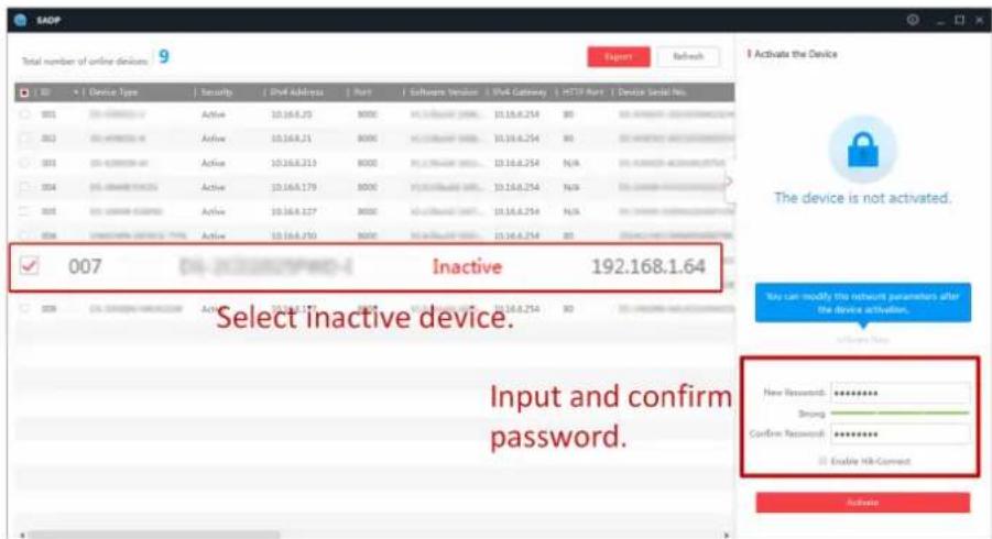
Status of the device becomes Active after successful activation.
5. Modify IP address of the device.
1) Select the device.
2) Change the device IP address to the same subnet as your computer by either modifying the IP address manually or checking Enable DHCP.
3) Input the admin password and click Modify to activate your IP address modification.
Chapter 4 Configuration
Configure the security control panel in the web client or the remote configuration page in client software.
4.1 Use the Client Software
Steps
-
Download, install and register to the client software.
-
Add device in Control Panel → Device Management → Device.

Set the device port No. as 80.

The user name and password when adding device are the activation user name and password.
- Click Remote Configuration to enter the device configuration page after the device is completely added,
4.2 Use the Web Client
Steps
-
Connect the device to the Ethernet.
-
Search the device IP address via the client software and the SADP software.
-
Enter the searched IP address in the address bar.

When using mobile browser, the default IP Address is 192.168.8.1. The device must be in the AP mode.

When connecting the network cable with computer directly, the default IP Address is 192.0.0.64
- Use the activation user name and password to login.

Refer to Activation chapter for the details.
4.2.1 Communication Settings
Wired Network
If the device is linked to the wired network, you can set the wired network parameters when you want to change the device IP address and other network parameters.
Steps

The function is not supported by some device models.
- In iVMS-4200 client software, enter the Device Management page.
- Select the device in the Device for Management list, click Remote Configuration.
- Click Communication Parameters → Ethernet to enter the Wired Network Parameters page.
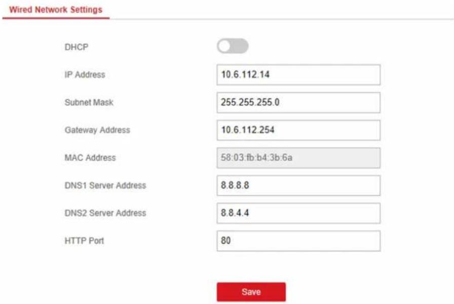
Figure 4-1 Wired Network Settings Page
-
Set the parameters.
-
Automatic Settings: Enable DHCP and set the HTTP port.
- Manual Settings: Disabled DHCP and set IP Address, Subnet Mask, Gateway Address, DNS Server Address.

By default, the HTTP port is 80.
- Optional: Set correct DNS server address if the device needs to visit Hik-Connect server via a domain name.
6. Click Save.
Wi-Fi
You can set the Wi-Fi parameters if there are secure and credible Wi-Fi networks nearby.
Steps
- Click Communication Parameters → Wi-Fi to enter the Wi-Fi page.
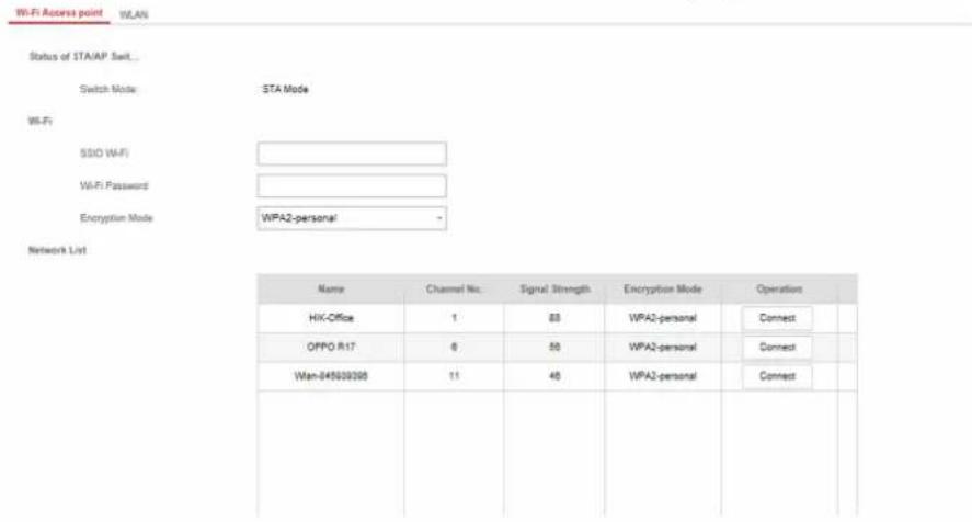
Figure 4-2 Wi-Fi Settings Page
-
Connect to a Wi-Fi.
-
Manually Connect: Input the SSID Wi-Fi and Wi-Fi Password, select Encryption Mode and click Save.
-
Select from Network List: Select a target Wi-Fi from the Network list. Click Connect and input Wi-Fi password and click Connect.
-
Click WLAN to enter the WLAN page.
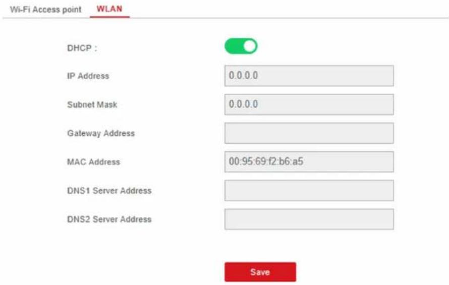
Figure 4-3 WLAN Settings Page
- Set IP Address, Subnet Mask, Gateway Address, and DNS Server Address.

If enable DHCP, the device will gain the Wi-Fi parameters automatically.
- Click Save.
Cellular Network
Set the cellular network parameters if you insert a SIM card inside the device. By using the cellular network, the device can upload alarm notifications to the alarm center.
Before You Start
Insert a SIM card into the device SIM card slot.
Steps
- Click Communication Parameters → Cellular Data Network to enter the Cellular Data Network Settings page.
Cellular Data Network Settings
Enable GPRS/3G/4G
Phone Number
User Name
Access Password
APN
MTU
PIN Code
Data Usage Limit
Data Used This Month
Data Limited per Month

*99***1#



1400




Save
Figure 4-4 Cellular Data Network Settings Page
- Enable Wireless Dial.
- Set the cellular data network parameters.
Access Number
Input the operator dialing number.
User Name
Ask the network carrier and input the user name.
Access Password
Ask the network carrier and input the password.
APN
Ask the network carrier to get the APN information and input the APN information.
Data Usage Limit
You can enable the function and set the data threshold every month. If data usage is more than the configured threshold, an alarm will be triggered and uploaded to the alarm center and mobile client.
Data Used This Month
The used data will be accumulated and displayed in this text box.
- Click Save.
Alarm Center
You can set the alarm center's parameters and all alarms will be sent to the configured alarm center.
Steps
- Click Communication Parameters → Alarm Receiving Center to enter the Alarm Receiving Center page.
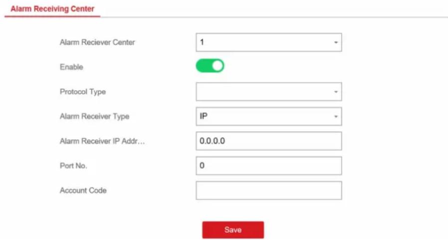
Figure 4-5 Alarm Receiving Center Parameters
- Select the Alarm Receiver Center as 1 or 2 for configuration, and slide the slider to enable the selected alarm receiver center.

Note
Only if the alarm receiver center 1 is enabled, you can set the alarm receiver center 2 as the backup channel and edit the channel parameters.
- Select the Protocol Type as ADM-CID, EHome, SIA-DCS, *SIA-DCS, *ADM-CID, or PSTN-CID to set uploading mode.
- ADM-CID or SIA-DCS
You should select the Alarm Receiver Type as IP or Domain name, and enter the IP/domain name, port number, account code, timeout, re-upload times and heartbeat interval.
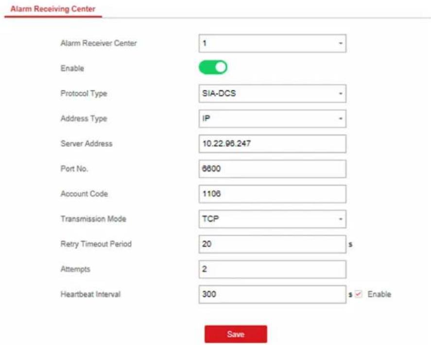
Figure 4-6 SIA-DCS
i Note
Set the heartbeat interval with the range from 10 to 3888000 seconds.
- EHome
You do not need to set the EHome protocol parameters.
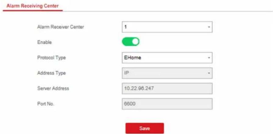
Figure 4-7 EHome
- *SIA-DCS or *ADM-CID
You should select the Alarm Receiver Type as IP or Domain name, and enter the IP/domain name, port number, account code, retry timeout period, attempts, heartbeat interval, encryption arithmetic, password length and secret key.
Alarm Receiving Center
Alarm Receiver Center
1
Enable

Protocol Type
*ADM-CID
Address Type
IP -
Server Address
10.22.98.247
Port No.
6600
Account Code
1106
Transmission Mode
TCP
Retry Timeout Period
20 s
Attempts
2
Heartbeat Interval
300 s ☑ Enable
Encryption Arithmetic
AES
Password Length
128
Secret Key
√

Figure 4-8 *ADM-CID
iNote
Set the heartbeat interval with the range from 10 to 3888000 seconds.
For encryption arithmetic: The panel support encryption format for information security according to DC-09, AES-128, AES-192 and AES-256 are supported when you configure the alarm center.
For the secret key: When you use an encrypted format of DC-09, a key should be set when you configure the ARC. The key would be issued offline by ARC, which would be used to encrypt the message for substitution security.
- PSTN-CID
You should enter the center name, center number, dialing times, and select communication protocol, transmission mode, receiver account.
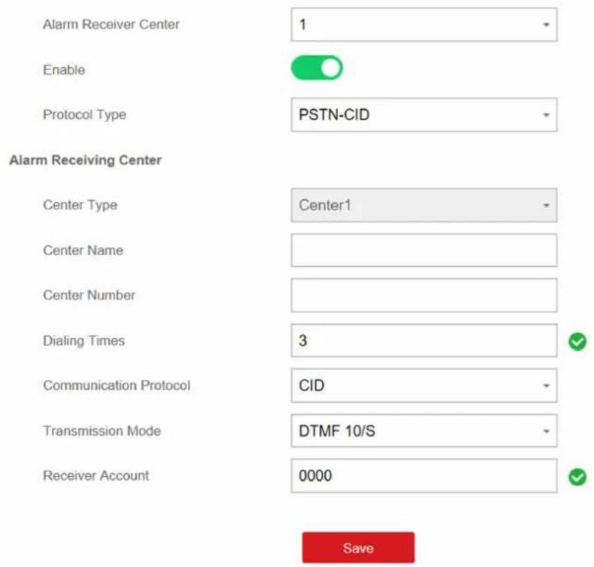
Figure 4-9 PSTN-CID
4. Click Save.
Notification Push
When an alarm is triggered, if you want to send the alarm notification to the client, alarm center, cloud or mobile phone, you can set the notification push parameters.
Steps
- Click Communication Parameters → Event Communication.
- Enable the target notification.
Alarms and Tampers
The device will push notifications when the zone alarm is triggered or the device tamper alarm is triggered or restored.
Life Safety Alarms
The device will push notifications when fire alarm, gas alarm, or medical alarm is triggered.
Maintenance and Faults
The device will push notifications when any status in the system is changed.
Panel Management Notification
The device will push notifications when the user operate the device.

Note
If you want to send the alarm notifications to the mobile client, you should also set the Mobile Phone Index, Mobile Phone Number, and check the Notification Type.

Note
For message notification in alarm receiving center, select the center index before settings.
3. Click Save.
- Check the paritions you need in Arming Permission, Disarming Permission and Alarm Clearing Permission.
Result
Table 4-1 Options of Notifications
| OptionNotification | |
| iVMS-4200 Alarms and Tampers | Life Safety AlarmsMaintenance and FaultsPanel Management Notification |
| Alarm Receiver Center Alarm Receiver Center 1&2 | Alarms and TampersLife Safety AlarmsMaintenance and FaultsPanel Management Notification |
| Cloud Alarms and Tampers | Life Safety AlarmsMaintenance and FaultsPanel Management Notification |
| Mobile Phone Mobile Phone Index 1 to 8 | Mobile Phone NumberNotification Type SMSAlarms and TampersLife Safety AlarmsMaintenance and FaultsOperation Events |

Note
You can arm/disarm/clear alarm via sending SMS. The number of the SIM card installed in the control panel is the receiver number.
The control massage is Command + Operation Type + Target, and the details are show below. For examples, command 00+1+1 indicates partition 1 disarming, and command 01+1+1 indicates partition 1 away arming.
| Command Operation | Type Target | |
| 2 Digits00: Disarming01: Away Arming02: Stay Arming03: Alarm Clearing | 1 Digit1: Partition Operation | No more than 3 Digits0: All partition arming/disarming/clearing Alarm1: Partition 1 arming/disarming/clearing Alarm...13: Partition 13 arming/disarming/clearing Alarm... |
Hik-Connect
If you want to register the device to the Hik-Connect mobile client for remote configuration, you should set the Hik-Connect registration parameters.
Before You Start
- Connect the device to the network via wired connection, dial-up connection, or Wi-Fi connection.
- Set the device IP address, subnet mask, gateway and DNS server in the LAN.
Steps
- Click Communication Parameters → Hik-Connect Registration to enter the Hik-Connect Registration Settings page.
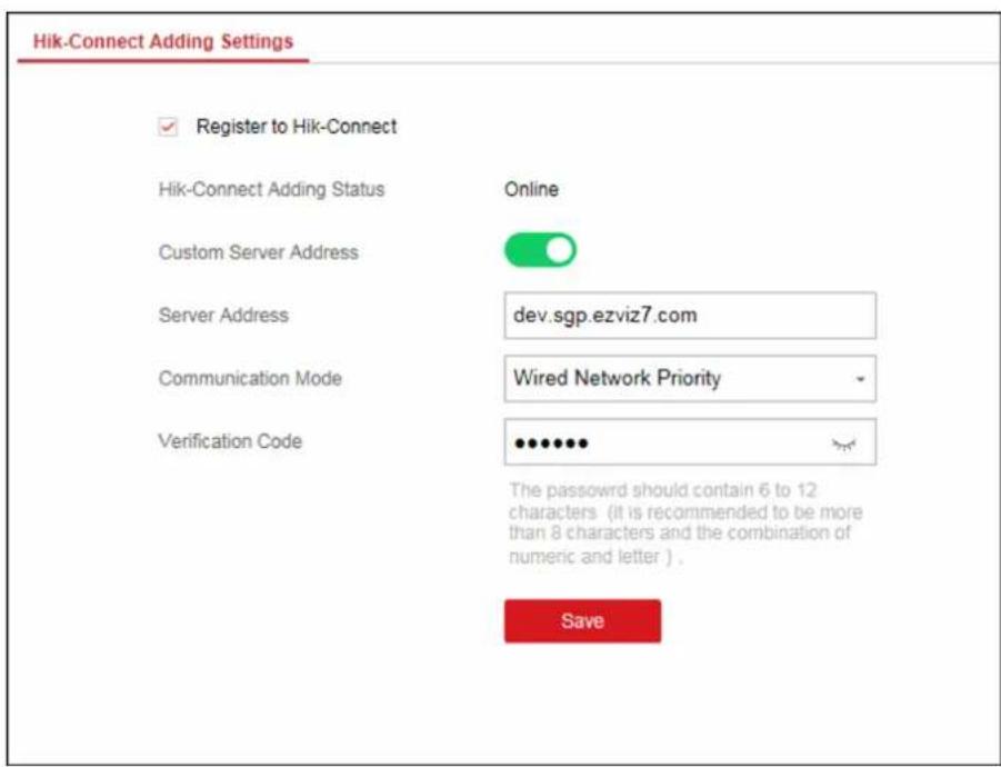
Figure 4-10 Hik-Connect Registration Settings Page
- Check Register to Hik-Connect.

Note
By default, the device Hik-Connect service is enabled.
You can view the device status in the Hik-Connect server (www.hik-connect.com).
- Enable Custom Server Address.
The server address is already displayed in the Server Address text box.
- Select a communication mode from the drop-down list according to the actual device communication method.
Auto
The system will select the communication mode automatically according to the sequence of, wired network, Wi-Fi network, and cellular data network. Only when the current network is disconnected, will the device connect to other network.
Wired Network Priority
The wired network has the highest priority.

When the device supports cellular data network connection and the wired network is disconnected, it will connect to the cellular data network. When the wired network is
restored, only if the cellular data network is disconnected, does the device connect to the wired network.
Wired &Wi-Fi
The system will select wired network first. If no wired network detected, it will select Wi-Fi network.
Cellular Data Network
The system will select cellular data network only.
5. Optional: Change the authentication password.

Note
- By default, the authentication password is displayed in the text box.
- The authentication password should contain 6 to 12 letters or digits. For security reasons, an 8-character password is suggested, which containing two or more of the following character types: uppercases, lowercases, and digits.
6. Click Save.
EHome
In this section, you can create an EHome account, and edit the IP address/domain name, port number.
Steps
- Click Communication Parameters → Ehome Registration to enter the Ehome Registration Settings page.
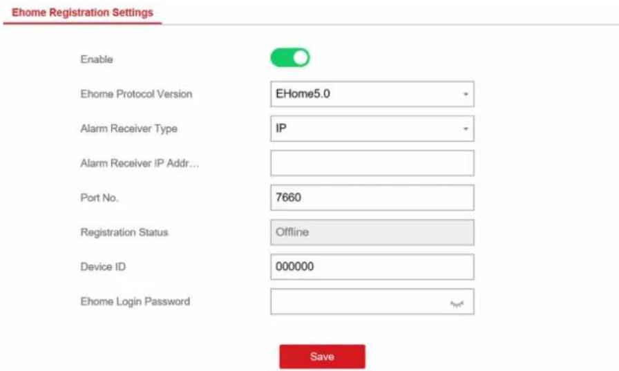
Figure 4-11 EHome Registration
-
Slide the slider to enable EHome protocol.
-
Select the Alarm Receiver Type as IP or Domain Name.
-
Input IP address or domain name according to the alarm receiver type.
-
Input the port number for the protocol.
By default, the port number for EHome is 7660.
-
Set an account, including the Device ID and Ehome Login Password.
-
Click Save.
NAT
Universal Plug and Play (UPnP™) is a networking architecture that provides compatibility among networking equipment, software and other hardware devices. The UPnP protocol allows devices to connect seamlessly and to simplify the implementation of networks in the home and corporate environments.
Enable the UPnP function, and you don't need to configure the port mapping for each port, and the device is connected to the Wide Area Network via the router.
Steps
- Click Communication Parameters → NAT to enter the page.
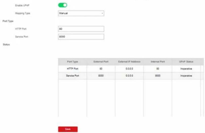
Figure 4-12 NAT Settings
- Check the checkbox to enable UPnP.
- Optional: Select the mapping type as Manual
- Set the HTTP port and the service port.
- Click Save to complete the settings
What to do next
Enter the tasks the user should do after finishing this task (optional).
Set FTP to Save Video
You can configure the FTP server to save alarm video.
Steps
-
Click Communication Parameters → FTP to enter the page.
-
Configure the FTP parameters
FTP Protocol
Uploads files via FTP.
Server Address and Port
The FTP server address and corresponding port.
User Name and Password
The FTP user should have the permission to upload pictures. If the FTP server supports picture uploading by anonymous users, you can check Anonymous to hide your device information during uploading.
Directory Structure
The saving path of snapshots in the FTP server.
What to do next
Enter the tasks the user should do after finishing this task (optional).
4.2.2 Device Management
Zone
You can set the zone parameters on the zone page.
Click Device Management → Zone to enter the Zone page.
Wired Zone Settings
Steps
- Select a wired zone and click 🔗 to enter the Zone Settings page.
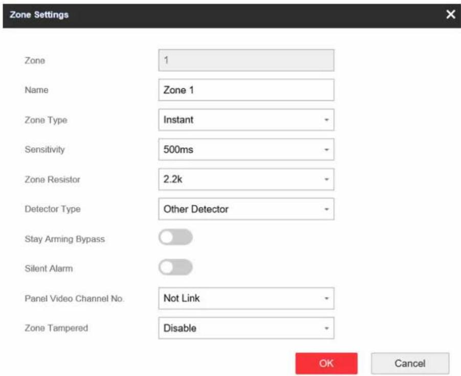
Figure 4-14 Wired Zone Settings
- Edit the zone name.
- Select a zone type.
Instant Zone
This Zone type will immediately trigger an alarm event when armed.
Delayed Zone
Exit Delay: Exit Delay provides you time to leave through the defense area without alarm.
Entry Delay: Entry Delay provides you time to enter the defense area to disarm the system without alarm.
The system gives Entry/Exit delay time when it is armed or reentered. It is usually used in entrance/exit route (e.g. front door/main entrance), which is a key route to arm/disarm via operating keyboard for users.

You can set 2 different time durations in Partition Management → Schedule & Timer.
Follow Zone
The zone acts as delayed zone when it detects triggering event during system Entry Delay, while it acts as instant zone otherwise.
Perimeter Zone
The system will immediately alarm when it detects a triggering event after the system is armed. There is a configurable interval timer between the alarm activation and siren output "Siren Delay Time (Perimeter Alarm) 0 to 600 Seconds". This option allows you to check the alarm and cancel the siren output during the interval time in case of false alarm.
When the zone is armed, you can set the peripheral alarm delayed time in Partition Management → Schedule & Timer. You can also mute the siren in the delayed time.
Silent Panic Zone
This zone type is active 24hrs, it is used for Panic or HUD (Hold Up Devices) not smoke sensors or break glass detectors.
Panic Zone
The zone activates all the time. It is usually used in the sites equipped with panic button, smoke detector and glass-break detector.
Fire Zone
The zone activates all the time with sound/siren output when alarm occurs. It is usually used in fire hazardous areas equipped with smoke detectors and temperature sensors.
Gas Zone
The zone activates all the time with sound/siren output when alarm occurs. It is usually used in areas equipped with gas detectors (e.g., the kitchen).
Medical Zone
The zone activates all the time with beep confirmation when alarm occurs. It is usually used in places equipped with medical emergency buttons.
Timeout Zone
The zone activates all the time. The zone type is used to monitor and report the "ACTIVE" status of a zone, but it will only report and alarm this status after the programmed time has expired. (1 to 599) Seconds. It can be used in places equipped with magnetic contacts that require access but for only a short period (e.g., fire hydrant box's door or another external security box door)
Disabled Zone
Alarms will not be activated when the zone is triggered or tampered. It is usually used to disable faulty detectors.
- Set the zone sensitivity and zone resistor.

Note
The resistor wired on the on-board zone should be the same as the resistor configured on this page.
-
Select a detector type.
-
Enable Stay Arming Bypass, or Silent Alarm according to your actual needs.

Note
Some zones do not support the function. Refer to the actual zone to set the function.
- Select the panel video channel No. and zone tampering wiring mode.
- Click OK.

Note
After setting the zone, you can enter Status → Zone to view the zone status.
Wireless Zone Settings
Steps
- Select a wireless zone and click 🔗 to enter the Zone Settings page.
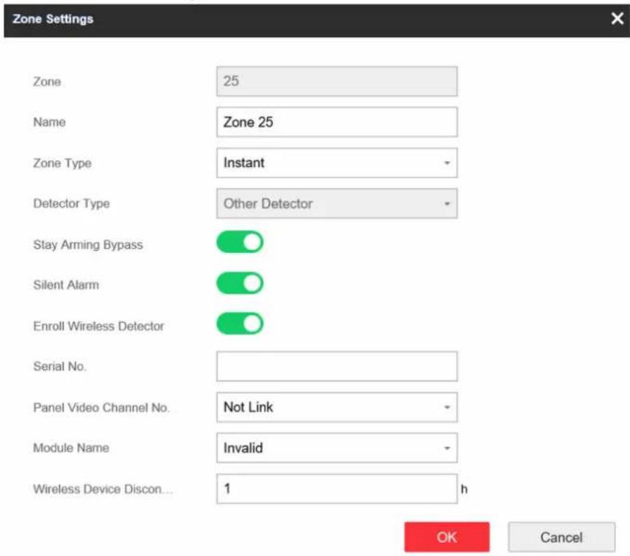
Figure 4-15 Wireless Zone Settings
- Edit the zone name.
- Select a zone type. For details, see Wired Zone Settings.
- Enable Stay Arming Bypass, Silent Alarm and Enroll Wireless Detector.
- Enter the serial No. to enroll the detector.
-
Select the module name.
-
Enter the wireless device disconnection duration.
-
Click OK.

After setting the zone, you can enter Status → Zone to view the zone status.
What to do next
Click Zone → Zone Module, you can see the zone module information including module status, module address, module channel No., and module type.
Relay
If you want to the link the device with a relay output to output the alarm, set the output parameters.
Steps
- Click Device Management → Relay to enter the Output page.
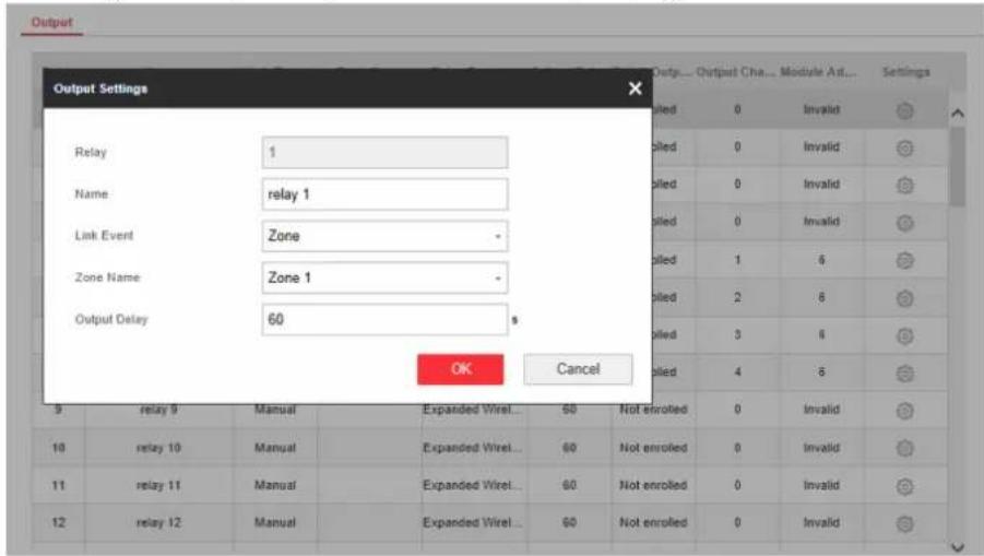
Figure 4-16 Wireless Output Module Settings
-
Click and the Relay Settings window will pop up.
-
Edit the relay name, select a link event, and set the output delay time duration.
-
Click OK.

After the relay is configured, you can click Status → Relay to view the output status.
Siren
The siren is enrolled to the control panel via the wireless receiver module, and the 868 Mhz wireless siren can be enrolled to the hybrid control panel via the wireless receiver that is at the address of 9.
Steps
-
Click Device Management → Siren to enter the Siren page.
-
Click 🔗 to enter the Siren Settings page.
- Wired Siren
Set the siren name and the linked event.
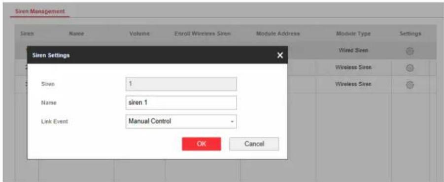
Figure 4-17 Wired Siren
- Wireless Siren
Enter the siren name and disconnection duration. Select the module name. Enable Enroll Wireless Siren and enter the serial No. of the detector.
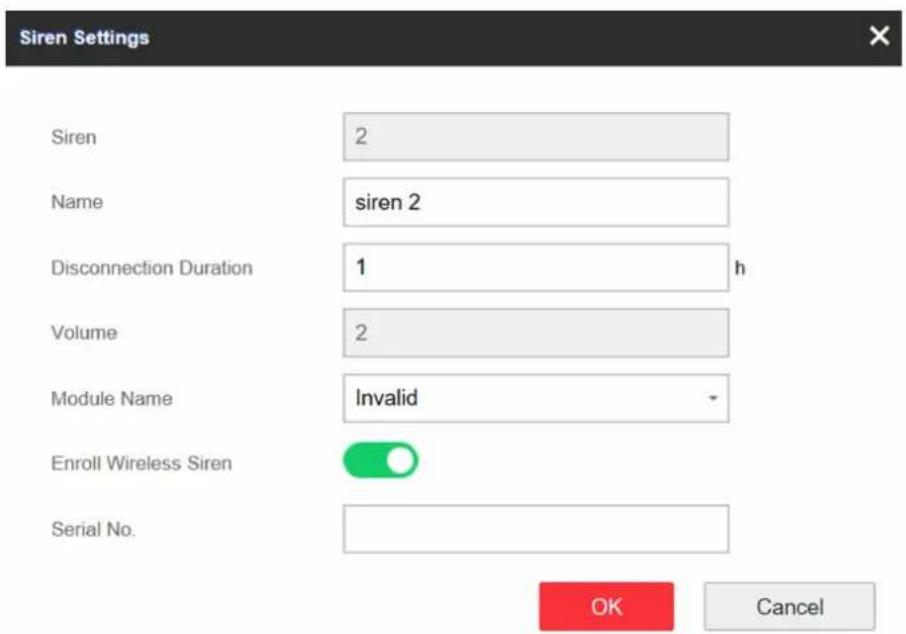
Figure 4-18 Wireless Siren
3. Click OK.

After the siren is configured, you can click Status → Siren to view the siren status.
Keypad
The keypad is connected to the control panel via RS-485 wiring. You can refer to Hybrid Control Panel Quick Start Guide for wiring details.
Steps
- Click Control Device → Keypad to enter the page.
- Click 🔗 to enter the Keypad Settings page.
- Set the keypad name.
- Select the keypad linked partition.
- Click OK.
Module
The wired module is connected to the control panel via RS-485 wiring. You can refer to the Hybrid Control Panel Quick Start Guide for details.
Steps
-
Click Device Management → Module Information to enter the page.
-
Click ⚙ to enter the module settings page.
- Set the module name.
- Click OK.
4.2.3 Partition Settings
Basic Settings
You can link zones to the selected partition.
Steps
- Click Partition Management → Basic Settings to enter the page.
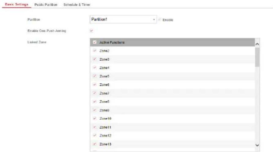
Figure 4-19 Partition Basic Information Management Page
- Select a partition.
- Check the Enable One-Push Arming to enable the One-Push Arming key on the keypad.
- Check the check box in front of the zone to select zones for the partition.
- Click Save to complete the settings.
Public Partition Settings
Definition Public partition is considered a special one which can be shared to other partitions. It is usually applied to manage or control the public area related with other areas controlled by other partitions in one building.
Steps
- Click Partition Management → Public Partition to enter the page.
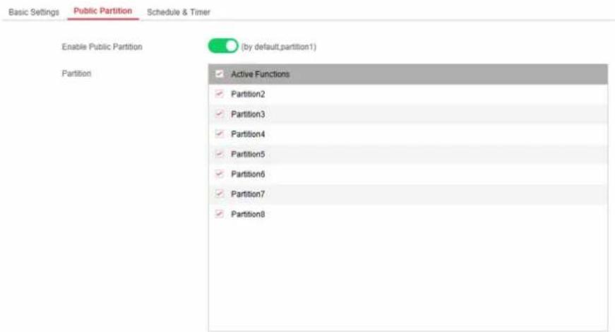
Figure 4-20 Public Partition Settings
- Check the checkbox to enable the public partition function.

the default public partition is partition 1
- Select partition(s) to link to the public partition in the list.

It is required to select at least a partition to link to the public partition.
- Click Save to set the partition as public partition.
Schedule and Timer Settings
You can set the Entry Delay 1 & Entry Delay 2 time duration for the delayed zone type and the Exit Delay delayed time to exit the zone. You can also set the alarm schedule. The zone will be armed/disarmed according to the configured time schedule.
Steps
- Click Partition Management → Schedule & Timer to enter the Schedule & Timer page.
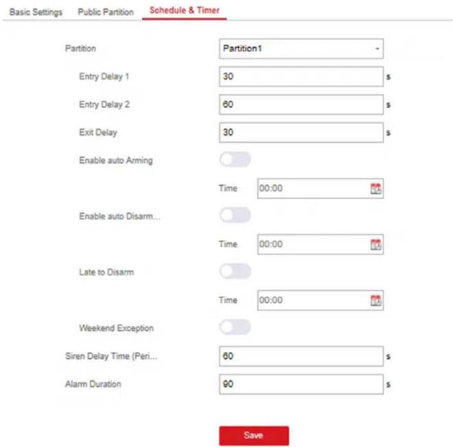
Figure 4-21 Schedule & Timer Settings
- Select a partition.
- Set time duration of Delay 1, Delay 2, or Exit Delay respectively.
Delay 1/Delay 2
If you have set the delayed zone, you can set the delayed time duration here.

The available time duration range is from 5s to 600s.
Exit Delay
If you want to exit the zone without triggering the alarm, you can set the exit delay duration.

The available time duration range is from 5 s to 600 s.
- Optional: Set the following parameters according to actual needs.
Enable Auto Arming
Enable the function and set the arming start time. The zone will be armed according to the configured time.

The auto arming time and the auto disarming time cannot be the same.

The buzzer beeps slowly 2 minutes before the auto arming starts, and beeps rapidly 1 minute before the auto arming starts.

You can select to enable forced arming on the System Options page. While the function is enabled, the system will be armed regardless of the fault.

If the public partition is enabled, the partition 1 dose not support auto arming.
Enable Auto Disarming
Enable the function and set the disarming start time. The zone will be disarmed according to the configured time.

The auto arming time and the auto disarming time cannot be the same.

If the public partition is enabled, the partition 1 dose not support auto disarming.
Late to Disarm
Enable the function and set the time. If the alarm is triggered after the configured time, the person will be considered as late.

You should enable the Panel Management Notification function in Communication Parameters → Event Communication before enabling the Late to Disarm function.
Weekend Exception
Enable the function and the zone will not be armed in the weekend.
Siren Delay Time (Perimeter Alarm)
If you have set the perimeter zone, you can set the delayed time for the zone.

The available time duration range is from 0 s to 600 s.
Alarm Duration
Set the time duration of the alarm.

The available time duration range is from 1 s to 900 s.
5. Click Save.
4.2.4 Video Management
You can add 4 network cameras to the security control panel, and link the camera with the selected zone for video monitoring. You can also receive and view the event video via client and Email.
Add Cameras to the Security Control Panel
Steps
- Click Device Management → Channel to enter the network camera management page.
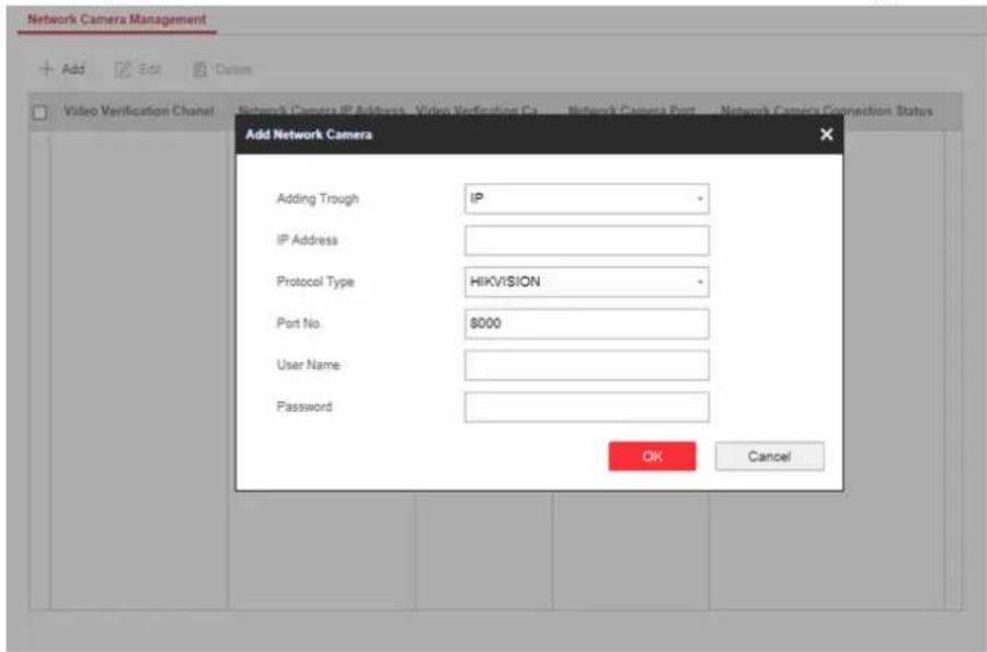
Figure 4-22 Network Camera Management
- ClickAdd, and enter the basic information of the camera, such as IP address and port No., and select the protocol type.
- Enter the user name and password of the camera.
-
Click OK.
-
Optional: Click Edit or Delete to edit or delete the selected camera.
Link a Camera with the Zone
Steps
- Click Device Management → Zone to enter the configuration page.
- Select a zone that you wish to include video monitoring, and click the Settings icon.
- Select the Panel Video Channel No..
- Click OK.
Set Email to Receive Alarm Video
You can send the alarm video or event to the configured email.
Steps
- Click Communication Parameters → Video Verification Events to enter the page.
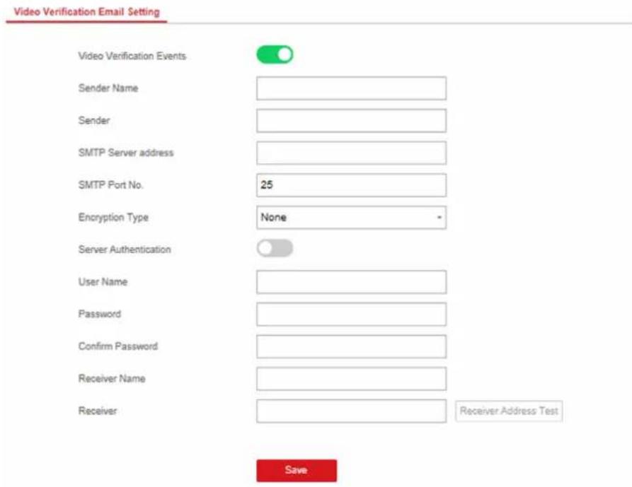
Figure 4-23 Set Email to Receive Alarm Video
- Click the block to enable the function.
- Enter the sender's information.
- Enter the receiver's information.
- Click Receiver Address Test and make sure the address is correct.
- Click Save.
Set Video Parameters
Steps
- Click Video & Audio → Event Video Parameters to enter the page.
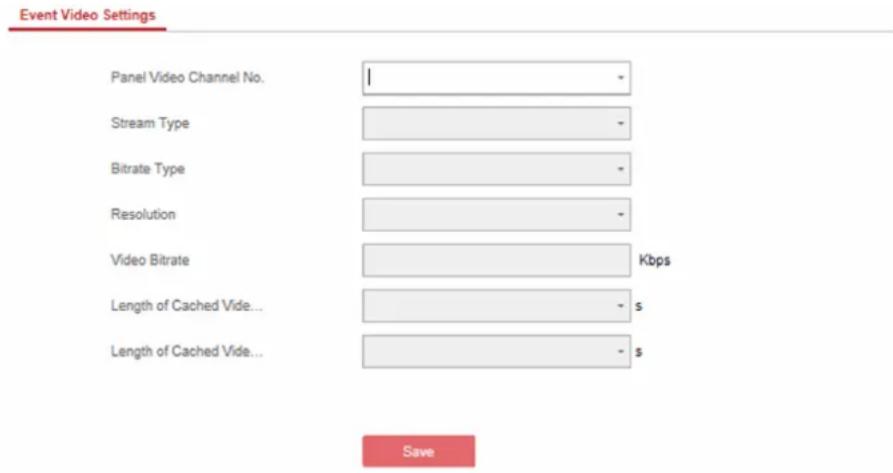
Figure 4-24 Video Settings
- Select a camera and set the video parameters.
Stream Type
Main Stream: Being used in recording and HD preview, it has a high resolution, code rate and picture quality..
Sub-Stream: It is used to transmit network and preview pictures as a video streaming with features of lower resolution, bit rate and picture quality.
Bitrate Type
Select the Bitrate type as constant or variable.
Resolution
Select the resolution of the video output
Video Bitrate
The higher value corresponds to the higher video quality, but the better bandwidth is required.
4.2.5 Permission Management
Add/Edit/Delete User
Administrator can add user to the security control panel, edit the user information, or delete the user from the security control panel. You can also assign different permissions to the new user.
Steps
-
Click User Management → User to enter the User Management page.
-
To compliant the EN requirement, slide the block to enable the setter and manufacturer.

Note
The default password of the setter is setter12345, and the default password of the manufacturer is hik12345. These codes will have to be changed when first connected.
3. Click Add.
- Set the new user's information in the pop-up window, including the user type, the user name, and the password.
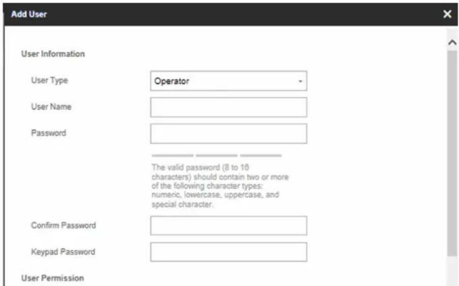
Figure 4-25 Add User Page
-
Set the keypad password (numeric, 4\~6 characters).
-
Check the check boxes to set the user permission.
The user can only operate the assigned permissions.
-
Click OK.
-
Optional: Enable the user in the Enable User column to allow the enabled user operating the device.
-
Optional: Select an user and click Edit and you can edit the user's information and permission.
-
Optional: Delete a single user or check multiple users and click Delete to delete users in batch.
The admin and the setter cannot be deleted.
Add/Edit/Delete Keyfob
You can add keyfob to the security control panel and you can control the security control panel via the keyfob. You can also edit the keyfobinformation or delete the keyfob from the security control panel.
Steps
- Click User Management → Keyfob to enter the Keyfob Management page.
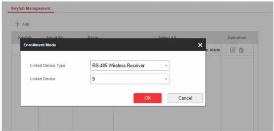
Figure 4-26 Keyfob Management
- Click Add and press any key on the keyfob.
- Set the keyfob linked device type and linked device No..
- Click OK.
- Optional: Click ☑ to edit the keyfob information.
- Optional: Delete a single keyfob or check multiple keyfobs and click Delete to delete the keyfobs in batch.
Add/Edit/Delete Tag (Card)
You can add tag to the security control panel and you can use the tag(card) to arm/disarm the zone. You can also edit the taginformation or delete the tag from the security control panel.
Steps
- Click User Management → Card to enter the management page.
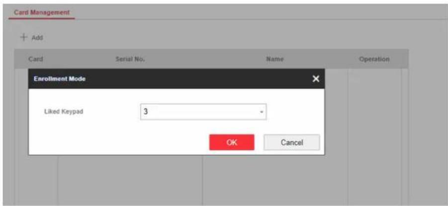
Figure 4-27 Tag Management
- Click Add to enter the adding page.
- Select the linked keypad.
- Click OK and the tag information will be displayed in the list.

The tag supports at least 20-thousand serial numbers.
- Optional: Click and you can change the tag(card) name.
- Optional: Delete a single tag(card) or check multiple tags(cards) and click Delete to delete cards in batch.
4.2.6 Maintenance
Test
The security control panel supports walk test function.
Steps
- Enter Maintenance → Test → to enable the function.
| Zone No. | Zone Name | Test Result |
| 1 | Wireless zone 1 | Invalid zone. |
| 2 | Wireless zone 2 | Invalid zone. |
| 3 | Wireless zone 3 | Invalid zone. |
| 4 | Wireless zone 4 | Invalid zone. |
| 5 | Wireless zone 5 | Invalid zone. |
| 6 | Wireless zone 6 | Invalid zone. |
| 7 | Wireless zone 7 | Invalid zone. |
| 8 | Wireless zone 8 | Invalid zone. |
| 9 | Wireless zone 9 | Invalid zone. |
-
Check the Test check box to start walk test.
-
Click Save to complete the settings.
- Trigger the detector in each zone.
- Check the test result.
Diagnosis
The control panel supports diagnosis of system, alarm, wireless device, Wi-Fi, and cloud platform
Steps
- Enter Maintenance → Diagnosis.
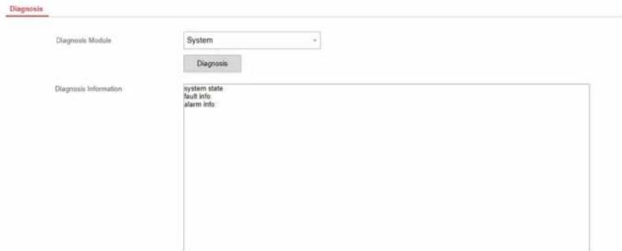
- Select system, alarm, wireless device, Wi-Fi, or cloud platform as the diagnosis module. Or you can select Custom, and enter the custom command (1\~64) characters.
- Click Diagnosis to start the operation.
- View the diagnosis result in the information box.
Export File
You can export debugging file to the PC.
Steps
- Click Maintenance → Export File to enter the page.
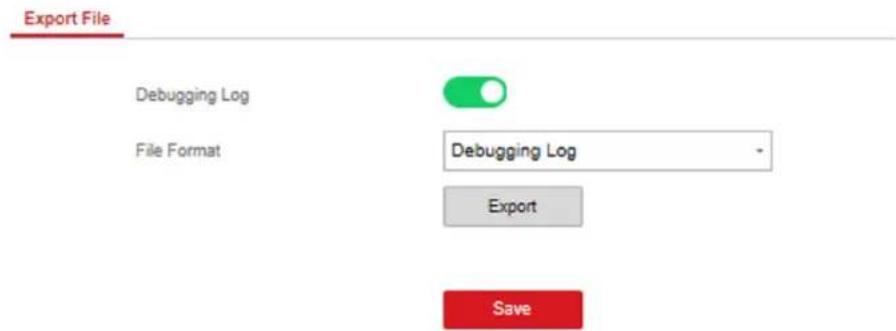
Figure 4-28 Export File Page
- Check the check box to enable the function.
- Click Export to save the debugging file in the PC.
4.2.7 System Settings
Authority Management
Set the authority options.
Click System → System Options to enter the Option Management page.
Forced Arming
If the option is enabled and there are active faults in a zone, the zone will be bypassed automatically.

Note
- You should disable the arming function in the Advanced Settings page. Or the forced arming function cannot be valid.
- If Enable Arming is enabled, Forced Arming is only effective for Auto Arming.
System Faults
If the option is enabled, the device will upload the system fault report automatically.
Authority Advanced Settings
Set advanced authority parameters.
Click System → System Options → Advanced Settings to enter the Advanced Settings page.
You can set the following parameters:
Enable Arming
When you enable the function, during the device arming procedure, the system will check the configured fault checklist. When there is fault occurred during the arming procedure, the procedure will be stopped.

Note
PKG keypad and the keyfob do not support this function. If this function is enabled, the arming will fail if there is a fault. It is necessary to eliminate the fault or close the Enable Arming.
Fault Checklist
The system will check if the device has the faults in the checklist during the arming procedure.
Enable Arming with Fault
Check the faults in the Enable Arming with Fault list, and the device will not stop the arming procedure when faults occurred.
Arming Indicator Keeps Light
If the device applies EN standard, by default, the function is disabled. In this case, if the device is armed, the indicator will be solid blue for 5 s. And if the device is disarmed, the indicator will flash 5 times.
When the function is enabled, if the device is armed, the indicator will be on all the time. And if the device is disarmed, the indicator will be off.

Note
Only -P model supports this function.
Prompt Fault When Arming
If the device applies EN standard, by default, the function is disabled. In this case, the device will not prompt faults during the arming procedure.

Note
Only -P model supports this function.
Enable Early Alarm
If you enable the function, when the zone is armed and the zone is triggered, the alarm will be triggered after the delay time.

Note
The early alarm will be taken effect only after the delayed zone is triggered.
Delay
When the early alarm function is enabled, you should set the delay time. The alarm will be triggered after the configured delay time.
Fault Check
The system determines whether to check the faults listed on the page. The system will only check the fault that is selected.
Detect Network Camera Disconnection
If the option is enabled, when the linked network camera is disconnected, an alarm will be triggered.
Battery Supervision
If the option is enabled, when battery is disconnected or out of charge, the device will not upload events.
Wired Network Fault Check
If the option is enabled, when the wired network is disconnected or with other faults, the alarm will be triggered.
Wi-Fi Fault Check
If the option is enabled, when the Wi-Fi is disconnected or with other faults, the alarm will be triggered.
Cellular Network Fault Check
If the option is enabled, when the cellular data network is disconnected or with other faults, the alarm will be triggered.
SIM Card Fault Check
If the option is enabled, the alarm will be triggered for faults of the SIM card.
Telephone Line Cut Off Detection
If the option is enabled, the alarm will be triggered when the phone line connected to the PSTN module disconnects.
RS-485 Exception Detection
If the option is enabled, the alarm will be triggered when the RS-485 bus of device has exception.
AC Power Down Check Time
The system checks the fault after the configured time duration after AC power down. The time duration should be set as 10 s.
Enrollment Method
Steps
- Click System → System Options → Adding Through to enter the enrollment method page.
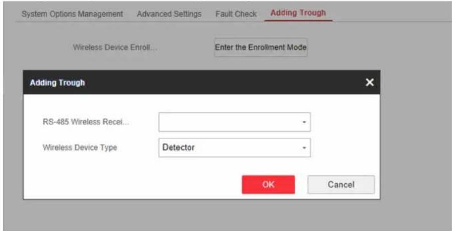
Figure 4-29 Enrollment Method
-
ClickEnter the Enrollment Mode.
-
In the pop-up window, Select a RS-485 wireless receiver.
- Select the wireless device type.
- Click OK to finish the enrollment settings.
Time Settings
You can set the device time zone, synchronize device time, and set the DST time. The device supports time synchronization via Hik-Connect server.
Time Management
Click System → Date and Time to enter the Time Management page.
You can select a time zone from the drop-down list.
You can synchronize the device time manually with NTP. Check the check box of NTP Time Sync., enter the server address and port No., and set the synchronization interval.
You can synchronize the device time manually. Or check Sync. with Computer Time to synchronize the device time with the computer time.
DST Management
Click System → Date and Time → DST Management to enter the Time Management page.
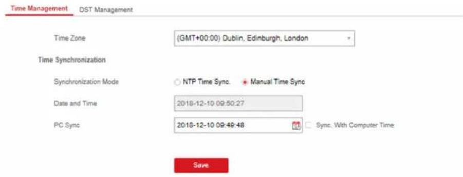
Figure 4-31 DST Management
You can enable the DST and set the DST bias, DST start time, and DST end time.
Security Settings
SSH Settings
Enable or disable SSH (Secure Shell) according to your actual needs.
Click System → Security → SSH Settings to enter the SSH Settings page and you can enable or disable the SSH function.
Locking User Settings
Set user locking. You can view the locked user or unlock a user and set the user locked duration.
Steps
-
Click System → Security → Locking User Settings to enter the Locking User Settings page.
-
Set the following parameters.
Max. Failure Attempts
If the user continuously input the incorrect password for more than the configured times, the account will be locked.

The administrator has two more attempts than the configured value.
Locked Duration
Set the locking duration when the account is locked.

The available locking duration is 5s to 1800s.
- Click 🔒 to unlock the account or click Unlock All to unlock all locked users in the list.
- Click Save.
Module Lock Settings
Set the module locking parameters, including the Max Failure Attempts, and locked duration. The module will be locked for the programmed time duration, once the module authentication has failed for the amount of configured times.
Steps
- Click System → Security → Module Lock Settings to enter the Module Lock Settings page.
- Select a module from the list, and click the Operation icon.
- Set the following parameters of the selected module.
Max. Failure Attempts
If a user continuously tries to authentication a password for more than the configured attempts permitted, the keypad will be locked for the programmed duration.
Locked Duration
Set the locking duration when the keypad is locked. After the configured duration, the keypad will be unlocked.
- Click OK.
- Optional: Click the Lock icon to unlock the locked module.
SSH Settings Locking User Settings Module Locking Settings
| No. | Device Type | Max. Failure Attempts | Locked Duration | Status | Operation |
| 1 | Keypad | 3 | 90 | Unlocked | |
| 2 | Keypad | 3 | 90 |  | |
| 3 | Keypad | 3 | 90 | Unlocked | |
| 4 | Keypad | 3 | 90 | Unlocked |
Figure 4-32 Module Lock Settings
System Maintenance
You can reboot the device, restore default settings, import/export configuration file, or upgrade the device remotely.
Select the device and click Remote Configuration in the client software, or enter the device IP address in the address bar of the web browser. Click System → System Maintenance to enter the Upgrade and Maintenance page.
Reboot
Click Reboot to reboot the device.
Click Partly Restore to restore all parameters except for admin user information, wired network, Wi-Fi network, detector information, and peripheral information to default ones.
Click Restore All to restore all parameters to the factorysettings.
Import Configuration File
Click View to select configuration file from the PC and click Import Configuration File to import configuration parameters to the device.
Export Parameters
Click Export Configuration File to export the device configuration parameters to the PC.
Upgrade File
Click View to select an upgrade file from the PC and click Upgrade to upgrade the device remotely.

Note
Do not power off when the device is upgrading.
Local Log Search
You can search the log on the device.
Click System → Log to enter the Local Log Search page.
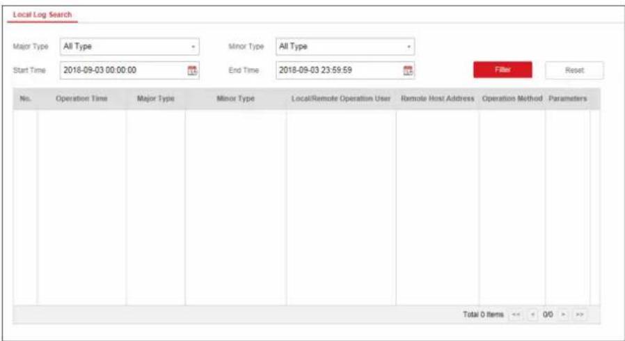
Figure 4-34 Local Log Search Page
Select a major type and a minor type from the drop-down list, set the log start time and end time and click Filter. All filtered log information will be displayed in the list.
You can also click Reset to reset all search conditions.
4.2.8 Check Status
After setting the zone, repeater, and other parameters, you can view their status.
Click Status. You can view the status of zone, relay, siren, battery, communication, and repeater.
• Zone: You can view the zone status, alarm status, detector battery capacity, and signal strength.
- Siren: You can view siren status, battery status, and signal strength.
- Relay: You can view relay status, battery status, and signal strength.
- Battery: You can view the battery charge.
- Communication: You can view the wired network "STATUS", Wi-Fi status, Wi-Fi signal strength, cellular network status, used data, and cloud connection status.
4.3 Use Mobile Client
4.3.1 Download and Login the Mobile Client
Download the Hik-Connect mobile client from Google Play (for Android) or App store (for iOS) and login the client before operating the security control panel.
Steps
- Search and download Hik-Connect mobile client from Google Play (for Android) or App Store (for iOS).
- Optional: Register a new account if it is the first time you use the Hik-Connect mobile client.

For details, see User Manual of Hik-Connect Mobile Client.
- Run and login the client.
4.3.2 Add Control Panel to the Mobile Client
Add a control panel to the mobile client before other operations.
Steps
- Power on the control panel.
- Select adding type.
- Tap → Scan QR Code to enter the Scan QR code page. Scan the QR code on the control panel.

Normally, the QR code is printed on the label stuck on the back cover of the control panel.
- Tap → Manual Adding to enter the Add Device page. Input the device serial No. with the Hik-Connect Domain adding type.
- Connect to a network.
1) Tap Connect to a Network.
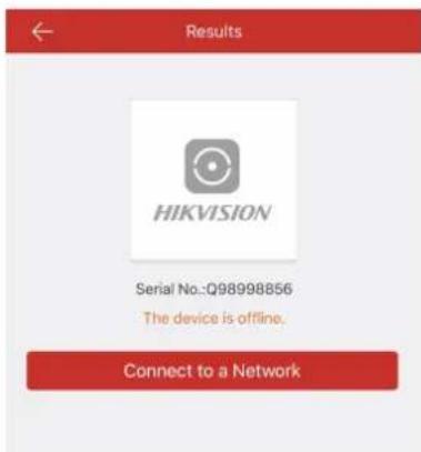
Figure 4-35 Connect to a Network Page
2) Tap Wireless Connect on the Select Connection Type page.
3) Follow the instructions on the Turn on Hotspot page and change the control panel to the AP mode. Tap Next.

You need to remove the rear panel of the device and the AP/STA switch is on the back of the device.
4) Select a stable Wi-Fi for the device to connect and tap Next.

Make sure the device and the mobile phone are connect to the same Wi-Fi.
- Follow the instructions on the Device's Wi-Fi page and connect the mobile phone with the control panel via wireless connection.

Select HAP-Device Serial No. as the hotspot and enter the hotspot password. By default, the password is AP + Device Verification Code. The verification code is normally printed on the device label.
- Return to the mobile client and create a device password for device activation.

We highly recommend you to create a strong password of your own choosing (using a minimum of 8 characters, including at least three kinds of following categories: upper case letters, lower case letters, numbers, and special characters) in order to increase the security of your product. And we recommend you reset your password regularly, especially in the high security system, resetting the password monthly or weekly can better protect your product.
- Optional: If you add the control panel by entering its serial No., you should enter the device verification code and tap OK.

By default, the verification code is printed on the device label.
- Follow the instructions and change the control panel to the Station mode. Tap Next.

You need to remove the rear panel of the device and the AP/STA switch is on the back of the device.
- When the control panel adding is completed, tap Finish.
The control panel is listed on the Hik-Connect page.
4.3.3 Add Peripheral to the Control Panel
It is required to enter the activation name and the password login the control panel after it being added. The tampering alarm will not be detected within 5 minutes after you login the device as a setter and does not operate the device.
Before You Start
Make sure the control panel is disarmed.
Steps

Note
Some control panel models do not support add zones or wireless devices remotely. You should add them to the control panel directly. For details, see the user manual of the wireless device.
- Tap to enter the Scan QR Code page.
- Scan the peripheral's QR code to add the peripheral.
- Select a peripheral type, and create a name for the peripheral.

Note
- When the adding peripheral is a detector, the detector will be linked to the zone. You can view the detector information in the Zone tab.
- Up to 32 detectors can be linked to the zone.
The added peripheral will be listed in the Zone tab or the Wireless Device tab.

Note
One of the most important factors for a reliable wireless installation is the signal strength between a wireless device and the panel. If a device is out of range it will not be able to send events to the control panel therefore it is recommended that a signal strength test is performed before fixing devices into place. The control panel has advanced signal strength mechanism that operates by monitoring all inputs/bells on the web browser. The page will need to be re-freshed every time for a new test. See also Appearance-Function Button.
When performing a signal strength test it is recommended that the system is tested in the ‘worst case scenario’ for example with all doors and windows closed.
4.3.4 Add a Camera to the Zone
You can link a camera to the zone to monitor the zone. You can view the alarm videos when an alarm is triggered.
Before You Start
Make sure you have installed the camera in the target zone and the camera has connected the same LAN as the security control panel's.
Steps
- Tap a security control panel on the Hik-Connect page and tap Zone to enter the zone list page.
- Select a zone to enter the zone settings page.
- Tap Link Camera to enter the Link Camera page.
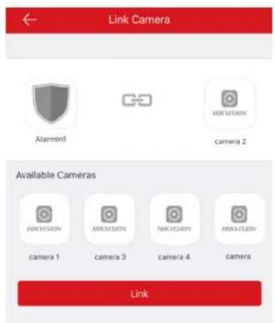
Figure 4-36 Link Camera Page
- Select a camera in the available cameras, and tap Link.
The selected camera will be linked to the zone. The icon ⬇ will be displayed on the right of the zone in the zone list. Tap the icon to view the zone live video.
4.3.5 Set Zone
After the detector is added, you can set the zone, including the zone name, the zone type, zone bypass, linked camera, stay/away status, the siren, and the silent zone. You can also view the detector serial No. (only device in 433 Hmz) and the detector type of the zone.
Steps
-
Tap a zone in the Partition page to enter the zone settings page.
-
Set the following parameters as you desired.
Detector Type
Select a detector type of the zone from the list
Zone Type
Select a zone type from the zone type list.
Zone Bypass
Enable the function and the zone will be bypassed. No alarm will be received while the zone is bypassed.
Link Camera
You can link the zone to cameras. When an alarm is triggered, you can monitor the zone via the linked cameras.
4.3.6 Arm/Disarm the Zone
Arm or disarm the zone manually as you desired.
On the Hik-Connect page, tap a security control device to enter the control panel management page. Tap Away/Stay/Disarm to control the partition's status.
You can also tap Clear Alarm to clear the alarm when an alarm is triggered.
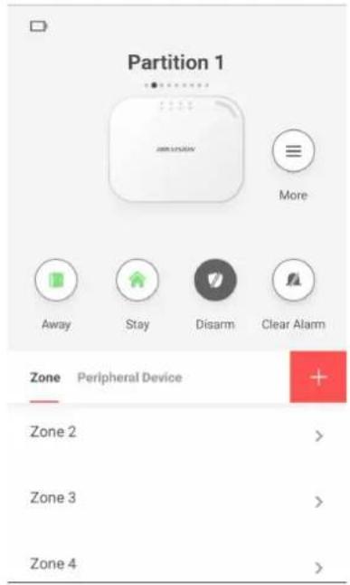
Figure 4-37 Control Panel Management Page
4.3.7 Set Arming/Disarming Schedule
Set the arming/disarming schedule to arm/disarm a particular zone automatically.
Tap a security control panel to enter the control page and tap or to enter the Settings page. Enable the auto arm/disarm function and set the auto arm time/auto disarm time. You can also set the late to disarm time, entry delay time, exit delay time, and siren delay time.
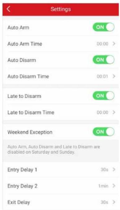
Figure 4-38 Arming or Disarming Schedule Page
4.3.8 Bypass Zone
When the partition is armed, you can bypass a particular zone as you desired.
Before You Start
Link a detector to the zone.
Steps
- Select a zone in the Zone tab of the Partition page to enter the settings page.
- Select a zone and enter the Settings page.
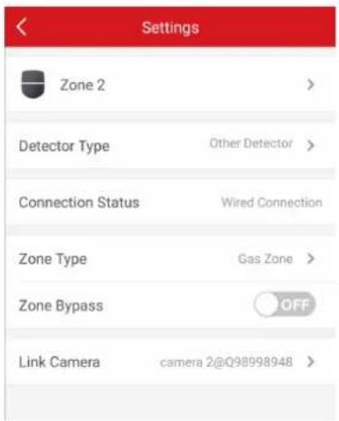
Figure 4-39 Zone Settings Page
- Enable Zone Bypass and the zone will be in the bypass status.
The detector in the zone does not detect anything and you will not receive any alarm from the zone.
4.3.9 Add Card
You can add card to the control panel. Use the card to arm, disarm, or clear alarm.
Steps
- Select a control panel on the Hik-Connect page to enter the control panel management page.
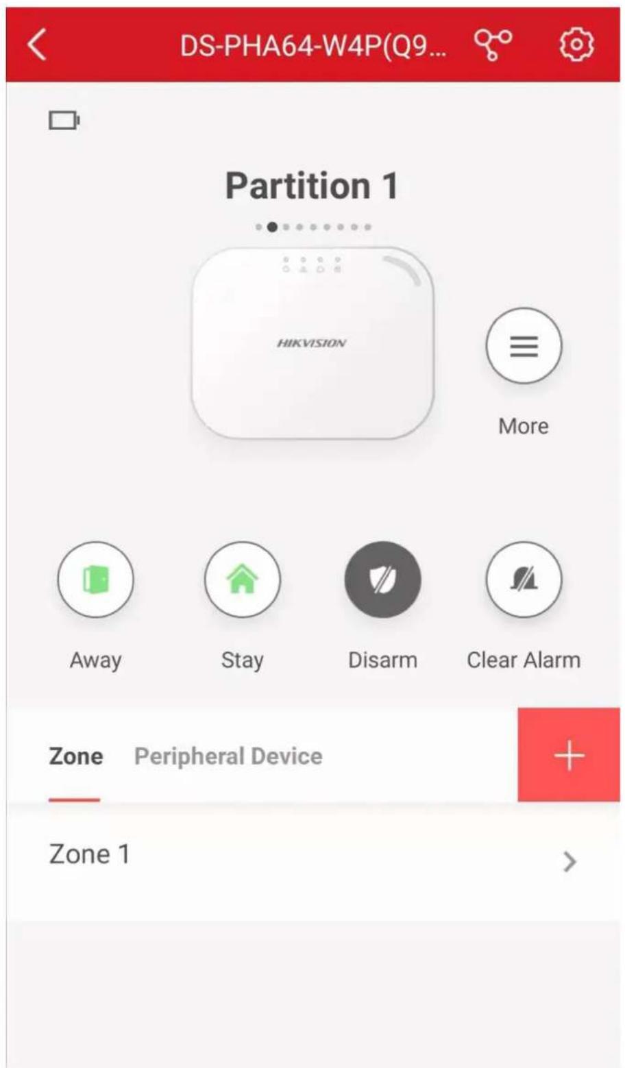
Figure 4-40 Control Panel Management Page
-
Tap 📋 → Card/Tag Management to enter the Card/Tag Management page.
-
Tap + .
-
When hearing the voice prompt "Swipe Card", you should present the card on the control panel card presenting area.
When hearing a beep sound, the card is recognized.
- Create a card alias and tap Finish.

The alias should contain 1 to 32 characters.
The card is displayed in the Card/Tag Management page.
4.3.10 Add Keyfob
You can add keyfobs to the control panel and control partition arming/disarming status. You can also clear alarm when an alarm is triggered.
Steps

Make sure the keyfob's frequency is the same as the control panel's.
-
Tap to enter the Add Keyfob page.
-
Follow the instruction on the page and press any key on the keyfob to add.
-
Create a name for the keyfob and tap Finish.
The keyfob is listed in the Wireless Device page.
- Optional: You can view the keyfob's serial No. and you can also delete it.
4.3.11 Check System Status (ZoneStatus/Communication Status)
You can view the zone status and the communication status via the mobile client.
View Zone Status
In the Partition page, tap Zone to enter the Zone tab. You can view the each zone's status in the list.
Communication Mode
Tap 📋 to enter the control panel settings page. You can view the device communication status, including the battery, Ethernet network, Wi-Fi, mobile network, and data usage.
4.3.12 Check Alarm Notification
When an alarm is triggered, and you will receive an alarm notification. You can check the alarm information from the mobile client.
Before You Start
• Make sure you have linked a zone with a detector.
- Make sure the zone is not bypassed.
- Make sure you have not enabled the silent zone function.
Steps
- Tap Notification in the Hik-Connect page to enter the page.
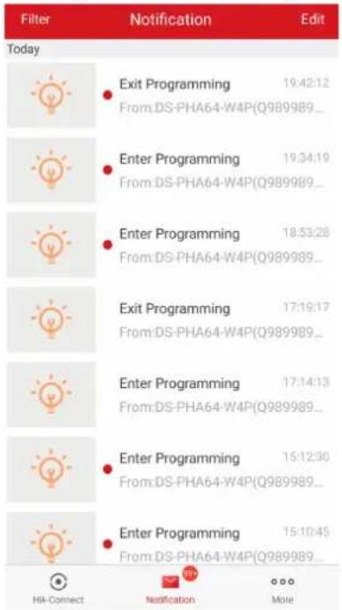
Figure 4-41 Notification
All alarm notifications are listed in Message page.
- Select an alarm and you can view the alarm details.
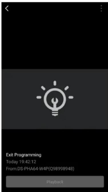
Figure 4-42 Notification Details
- Optional: If the zone has linked a camera, you can view the playback when the alarm is triggered.
Chapter 5 Operations
You can use the client keyfob, card, client software, or mobile client to do arming, disarming, bypass, and zone disabling.
5.1 Arming
You can use keypad, keyfob, card, clientsoftware, mobile client to arm your system.
After the arming command is sending to control panel, the sytem will check the detector status. If the detector is in fault, you will need to choose whether to arm the system with fault.
While the system is armed, the control panel will prompt the result in 5s, and upload the arming report.
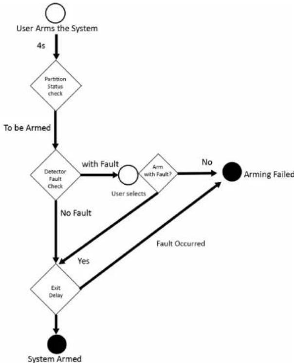
flowchart
graph TD
    A["User Arms the System"] -->|4s| B{Partition Status check}
    B -->|To be Armed| C{Detector Fault Check}
    C -->|No Fault| D{Exit Delay}
    C -->|with Fault| E{Arm with Fault?}
    E -->|No| F["Arming Failed"]
    E -->|Yes| D
    E -->|Fault Occurred| D
    F --> G["System Armed"]
Figure 5-1 Arming Process
Access level of Arming
The user in level 2 or 3 has the permission to arm or partly arm the system.
Arming Indication
The arming/disaring indicator keeps solid blue for 5s.
Reason of Arming Failure
- Intrusion detector triggered (excepts the detector on the exit route).
- Panic alarm device triggered.
- Tampering alarm occurred.
- Communication exception
- Mian power supply exception
- Backup battery exception
- Alarm receiving fault
- Siren fault
- Low battery of the keyfob
- Others
Arming with Fault
While the arming is stopped with fault, user in level 2 has the permission to arm the system with fault (forced arming).
Fored arming only takes effect on the current arming operation.
The forced arming operation will be record in the event log.
5.2 Disarming
You can disarm the system with keypad, keyfob, card, client software, or mobile client.
Disarming Indication
The arming/disarming indicator flashes 30s while the user successfully disarm the system through the entry/exit route.
The system will report the disarming result after the operation completed.
Entry Delay Duration
Set the entry delay duration within 45s to compliant the EN requirement.
Early Alarm
If either the intrusion or tampering alarm occurs on the enter/exit route when the control panel is in the status of entry delay, the control panel then enters the early alarm mode.
The early alarm duration can be set (> 30s).
The control panel will reports the alarm only if the alarm event lasts over the duration of early alarm with the addition of entry delay.
5.3 Use the Keyfob
The keyfod is used for away arming, stay arming, disarming, panic alarm, and clearing alarm.
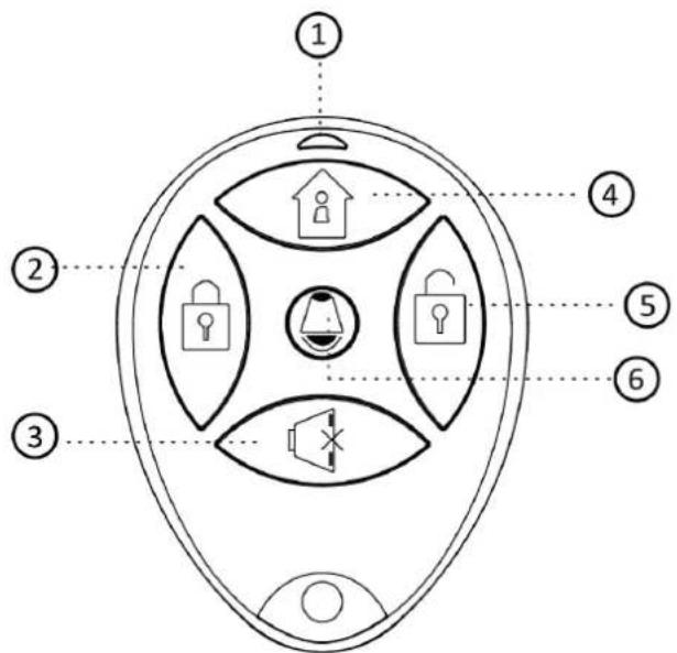
Figure 5-2 Type I Keyfob
Table 5-1 Type I Keyfob Keys
| No. Description | |
| 1 Indicator | Green: Successful OperationRed: Press the Key |
| 2 Away Arming | |
| 3 Clearing Alarm | |
| 4 Stay Arming | |
| 5 Disarming | |
| 6 Panic Alarm (Duress Alarm) | Hold the key for 2 seconds, an alarm report will be send to the alarm center secretly without alerting. |
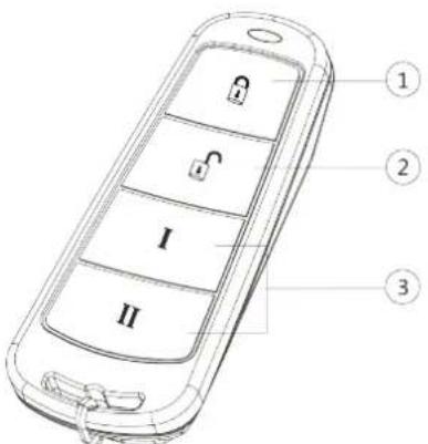
Figure 5-3 Type II Keyfob
Table 5-2 Type II Keyfob Keys
| No. Description | |
| 1 Arming (Lock) | |
| 2 Disarming( Unlock) | |
| 3 Combo-Function Key |
Custom Combination Functions (except Arming + II and Disarming + I) : Away Arming, Stay Arming, Disarming, Panic Alarm, Clearing Alarm, Fault Inspection, and Arming Status Check. The following table shows the keyfob operation and responded indications.
Table 5-3 Type II Keyfob Operations and Indications
| Keyfob Operation Result Indication | |
| Armed Red LED Flashes Once | |
| Arming Failed Green LED Flashes Once | |
| Arming Green LED Flashes 9 Times | |
| No Arming Permission Yellow LED Flashes 4 Times | |
| Fault Checking Finished Yellow LED Flashes 4 Times | |
| Alarm Cleared Green LED Flashes Once | |
| No Permission for Clearing Alarm Yellow LED Flashes 4 Times | |
| Disarmed Green LED Flashes Once | |
| No Disarming Permission Yellow LED Flashes 4 Times | |
| Panic Alarm Uploaded | Green LED Flashes Once |
| No Panic Alarm Permission | Yellow LED Flashes 4 Times |
5.4 Use the Card
It is poissible to arm or disarm the system with the card.
While the system is not armed, present a valid card to the control panel to arm the system.
While the system is armed, present a valid card to the control panel to disarm the system.
5.5 Use the Client Software
Steps
-
Download, install and register to the client software.
-
Add device in Control Panel → Device Management → Device.

Set the device port No. as 80.

The user name and password when adding device are the activation user name and password.
- Click Remote Configuration to enter the device configuration page after the device is completely added,
5.5.1 Accessing the Operation Page
Control partitions and it's related zones in the Security Control Panel module.

If there is no Security Control Panel displayed on the Control Panel page, click Selecting Modules, and select Security Control Panel
5.5.2 Partition Operation
In the Security Control Panel module, you can control the selected partition, such as away arming, stay arming, instant arming, disarming, clearing alarm, group bypass, and group bypass restoring.
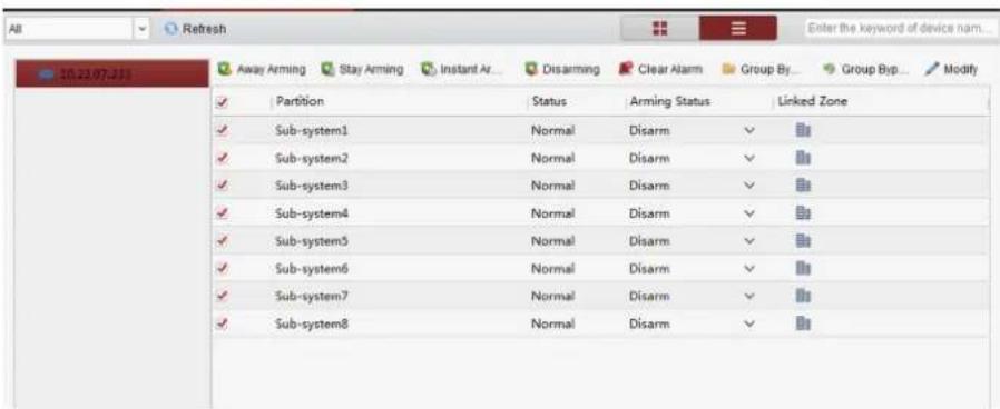
Figure 5-4 Partition Operation
Click Edit to edit the partition name and display options.
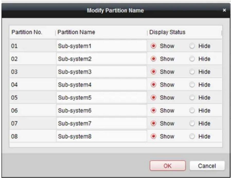
Figure 5-5 Editing Partition Information
5.5.3 Zone Operating
Click Linked Zone in the partition list of the Security Control Module. You can control the selected partition related zones, such as arming, disarming, bypass, or bypass restoring.
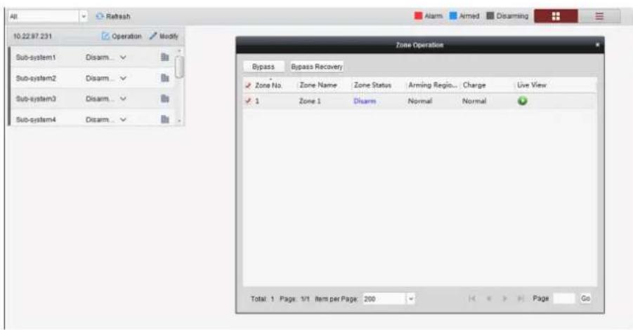
Figure 5-6 Zone Operation
5.6 Use the Web Client
Steps
-
Connect the device to the Ethernet.
-
Search the device IP address via the client software and the SADP software.
-
Enter the searched IP address in the address bar.

Note
When using mobile browser, the default IP Address is 192.168.8.1. The device must be in the AP mode.

Note
When connecting the network cable with computer directly, the default IP Address is 192.0.0.64
- Use the activation user name and password to login.

Note
Refer to Activation chapter for the details.
5.6.1 Add/Edit/Delete Tag (Card)
You can add tag to the security control panel and you can use the tag(card) to arm/disarm the zone. You can also edit the tag information or delete the tag from the security control panel.
Steps
- Click User Management → Card to enter the management page.
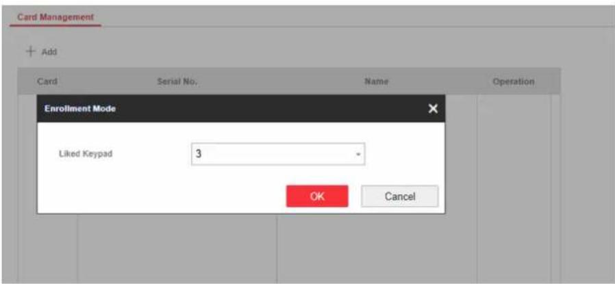
Figure 5-7 Tag Management
- Click Add to enter the adding page.
- Select the linked keypad.
- Click OK and the tag information will be displayed in the list.

The tag supports at least 20-thousand serial numbers.
- Optional: Click and you can change the tag(card) name.
- Optional: Delete a single tag(card) or check multiple tags(cards) and click Delete to delete cards in batch.
5.6.2 Add/Edit/Delete Keyfob
You can add keyfob to the security control panel and you can control the security control panel via the keyfob. You can also edit the keyfob information or delete the keyfob from the security control panel.
Steps
- Click User Management → Keyfob to enter the Keyfob Management page.

Figure 5-8 Keyfob Management
- Click Add and press any key on the keyfob.
- Set the keyfob linked device type and linked device No..
- Click OK.
- Optional: Click ☑ to edit the keyfob information.
- Optional: Delete a single keyfob or check multiple keyfobs and click Delete to delete the keyfobs in batch.
5.6.3 Add/Edit/Delete User
Administrator can add user to the security control panel, edit the user information, or delete the user from the security control panel. You can also assign different permissions to the new user.
Steps
- Click User Management → User to enter the User Management page.
- To compliant the EN requirement, slide the block to enable the setter and manufacturer.

Note
The default password of the setter is setter12345, and the default password of the manufacturer is hik12345. These codes will have to be changed when first connected.
- Click Add.
- Set the new user's information in the pop-up window, including the user type, the user name, and the password.
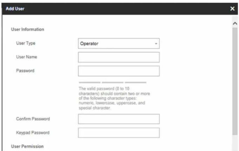
Figure 5-9 Add User Page
- Set the keypad password (numeric, 4\~6 characters).
- Check the check boxes to set the user permission.
The user can only operate the assigned permissions.
-
Click OK.
-
Optional: Enable the user in the Enable User column to allow the enabled user operating the device.
- Optional: Select an user and click Edit and you can edit the user's information and permission.
- Optional: Delete a single user or check multiple users and click Delete to delete users in batch.

The admin and the setter cannot be deleted.
5.6.4 Check Status
After setting the zone, repeater, and other parameters, you can view their status.
Click Status. You can view the status of zone, relay, siren, battery, communication, and repeater.
• Zone: You can view the zone status, alarm status, detector battery capacity, and signal strength.
- Siren: You can view siren status, battery status, and signal strength.
- Relay: You can view relay status, battery status, and signal strength.
- Battery: You can view the battery charge.
- Communication: You can view the wired network "STATUS", Wi-Fi status, Wi-Fi signal strength, cellular network status, used data, and cloud connection status.
Appendix A. Trouble Shooting
A.1 Communication Fault
A.1.1 IP Conflict
Fault Description:
IP that the panel automatically acquired or set is same as other devices, resulting in IP conflicts.
Solution:
Search the current available IP through ping. Change the IP address and log in again.
A.1.2 Web Page is Not Accessible
Fault Description:
Use browser to access web pages and display Inaccessible.
Solutions:
-
Check whether the network cable is loose and the panel network is abnormal.
-
The panel port has been modified. Please add a port to the web address for further access.
A.1.3 Hik-Connect is Offline
Fault Description:
The web page shows that the Hik-Connect is offline.
Solution:
Network configuration of the panel is error, unable to access extranet.
A.1.4 Network Camera Drops off Frequently
Fault Description:
System reports multiple event logs of IPC disconnection and connection.
Solution:
Check whether the network communication or camera live view is proper.
A.1.5 Failed to Add Device on APP
Fault Description:
When using APP to add devices, it is prompted that the device fails to be added, the device could not be found, etc.
Solution:
Check the web page: whether the Hik-Connect is offline.
A.1.6 Alarm Information is Not Reported to APP/4200/Alarm Center
Fault Description:
After the alarm is triggered, the app/4200/ alarm center does not receive the alarm message.
Solution:
"Message push" - "alarm and tamper-proof notice" is not enabled. You should enable "alarm and tamper-proof notice".
A.2 Mutual Exclusion of Functions
A.2.1 Unable to Enter Registration Mode
Fault Description:
Click the panel function key, and prompt key invalid.
Solution:
The panel is in "AP" mode. Switch the panel to "station" mode, and then try to enter the registration mode again.
A.2.2 Unable to Enter RF Signal Query Mode
Fault Description:
Double-click the host function key, and the prompt button invalid.
Solution:
The panel is in "AP" mode. Solution: switch the panel to "station" mode, and then try to enter the RF signal query mode again.
A.3 Zone Fault
A.3.1 Zone is Offline
Fault Description:
View status of zones which displays offline.
Solution:
Check whether the detector reports undervoltage. Replace the detector battery
A.3.2 Zone Tamper-proof
Fault Description:
View status of zones which displays tamper-proof.
Solution:
Make tamper-proof button of the detector holden.
A.3.3 Zone Triggered/Fault
Fault Description:
View status of zones which displays triggered/fault.
Solution:
Reset the detector.
A.4 Problems While Arming
A.4.1 Failure in Arming (When the Arming Process is Not Started)
Fault Description:
When the panel is arming, prompt arming fails.
Solution:
The panel does not enable "forced arming", and when there is a fault in the zone, the arming will fail. Please turn on the "forced arming" enable, or restore the zone to the normal status.
A.5 Operational Failure
A.5.1 Failed to Enter the Test Mode
Fault Description:
Failed to enable test mode, prompting "A fault in the zone".
Solution:
Zone status, alarm status or zone power is abnormal.
A.5.2 The Alarm Clearing Operation on the Panel Does Not Produce the Alarm Clearing Report
Fault Description:
The alarm clearing operation on the panel does not produce the alarm clearing report.
Solution:
In the absence of alarm, no report will be uploaded for arm clearing.
A.6 Mail Delivery Failure
A.6.1 Failed to Send Test Mail
Fault Description:
when configure the mail information, click "test inbox" and prompt test fails.
Solution:
Wrong configuration of mailbox parameters. Please edit the mailbox configuration information, as shown in table 1/1.
A.6.2 Failed to Send Mail during Use
Fault Description:
Check the panel exception log. There is "mail sending failure".
Solution:
The mailbox server has restricted access. Please log in to the mailbox to see if the mailbox is locked.
A.6.3 Failed to Send Mails to Gmail
Fault Description:
The receiver's mailbox is Gmail. Click "Test Inbox" and prompt test fails.
- Google prevents users from accessing Gmail using apps/devices that do not meet their security standards.
Solution:
Log in to the website (https://www.google.com/settings/security/lesssecureapps), and "start using access of application not safe enough". The device can send mails normally.
- Gmail does not remove CAPTCHA authentication.
Solution: Click the link below, and then click "continue" (https://accounts.google.com/b/0/displayunlockcaptcha).
A.6.4 Failed to Send Mails to QQ or Foxmail
Fault Description:
The receiver's mailbox is QQ or foxmail. Click "Test Inbox" and prompt test fails.
- Wrong QQ account or password.
Solution:
the password required for QQ account login is not the password used for normal login. The specific path is: Enter the email account → device → account → to generate the authorization code, and use the authorization code as the login password.
- SMTP login permission is needed to open.
A.6.5 Failed to Send Mails to Yahoo
Fault Description:
The receiver's mailbox is yahoo. Click "test inbox" and prompt test fails.
- The security level of mailbox is too high.
Solution:
Go to your mail account and turn on "less secure sign-in".
A.6.6 Mail Configuration
Table A-1 Mail Configuration
| Mail Type Mail Server SMTP Port Protocols Supported | |||
| Gmail smtp.gmail.com 587 TLS/STARTTLS (TLS) | |||
| Outlook smtp.office365.com587 STARTTLS (TLS) | |||
| Hotmail smtp.office365.com587 STARTTLS (TLS) | |||
| QQ smtp.qq.com 587 STARTTLS (TLSv1.2) | |||
| Yahoo smtp.mail.yahoo.com 587 STARTTLS (TLSv1.2) | |||
| 126 smtp.126.com | 465 SSL/TLS | ||
| Sina smtp.sina.com 25/465/587 SSL/TLS/STARTTLS | (SSL/TLS) | ||
| iNoteAbout mail configuration:SMTP portDefault to use port 25 without encryption, or using port 465 if SSL/TLS is used. Port 587 is mainly used for STARTTLS protocol mode.The STARTTLS protocol mode that is usually used by default when selecting TLS.User nameUser name of Outlook and Hotmail require full names, and other email require a prefix before @. | |||
Appendix B. Input Types
Table B-1 Input Types
| Input Types Operations | |
| Instant Zone The system will immediately alarm when it detects triggering event after system armed.Audible Response Trigger the system sound and siren.Voice Prompt: Zone X alarm. | |
| Perimeter Zone The system will immediately alarm when it detects triggering event after system armed.Audible Response: Trigger the system sound and siren. There is a configurable interval between alarm and siren output, which allows you to check the alarm and cancel the siren output during the interval.Voice Prompt: Zone X perimeter alarm. | |
| Delayed Zone The system provides you time to leave through or enter the defense area without alarm.Audible Response: Trigger the system sound and siren.Voice Prompt: Zone X alarm. | |
| Follow Zone The zone acts as delayed zone when it detects triggering event during system Entry Delay, while it acts as instant zone otherwise.Audible Response: Trigger the system sound and siren.Voice Prompt: Zone X follow alarm. | |
| 24H Silence Zone | The zone activates all the time without any sound/siren output when alarm occurs.Audible Response: No system sound (voice prompt or siren). |
| Panic Zone The zone activates all the time.Audible Response: Trigger the system sound and siren.Voice Prompt: Zone X panic alarm. | |
| Fire Zone | The zone activates all the time with sound/siren output when alarm occurs.Audible Response: Trigger the system sound and siren.Voice Prompt: Zone X fire alarm. |
| Gas Zone | The zone activates all the time with sound/siren output when alarm occurs.Audible Response: Trigger the system sound and siren.Voice Prompt: Zone X gas alarm. |
| Medical Zone | The zone activates all the time with beep confirmation when alarm occurs.Audible Response: Trigger the system sound and siren.Voice Prompt: Zone X medical alarm. |
| Timeout Zone | The zone activates all the time. The zone type is used to monitor and report the "ACTIVE" status of a zone, but it will only report and alarm this status after the programmed time has expired (1 to 599) seconds. |
| Disabled Zone | Alarms will not be activated when the zone is triggered or tampered.Audible Response: No system sound (voice prompt or siren). |
| Virtual Zone (Keypad/Keyfob) The system will immediately alarm when it detects triggering event after system armed.Audible Response: Trigger the system sound and siren.Voice Prompt: Buzzer beeps. | |
| Tamper Alarm The system will immediately alarm when it detects triggering event after system armed.Audible Response: Trigger the system sound and siren.Voice Prompt: Zone X tampered. | |
| Link Trigger the linked device when event occurs.e.g. The output expander linked relays will be enabled when the control panel is armed. | |
| Arm When armed: Voice prompt for fault. You can handle the fault according to the voice prompt.System sound for arming with card or keyfob.Voice prompt for fault. You can handle the fault according to the voice prompt.Fault event displays on client. You can handle the fault via client software or mobile client.Voice Prompt: Armed/Arming failed. | |
Appendix C. Output Types
Table C-1 Output Types
| Output Types ActiveRestore | ||
| Arming | Arm the control panel | After the configured output delay |
| Disarming | Disarm the control panel | After the configured output delay |
| Alarm When alarm event occurs. | The alarm output will be activated after the configured exit/enter delay. | After the configured output delay, disarm the control panel or clear alarm |
| Zone Linkage When alarm event | occurs, the linked relay will output alarm siganl. | After the configured output duration |
| Manual OperationEnable relays | manually Over the triggering time | or disable the relays manually |
Appendix D. Event Types
Table D-1 Event Types
| Event Types Custom Default 1 | (client software notification) | Default 2 (alarm receiving center 1/2) | Default 3 (mobile client) | Default 4 (telephone) | |
| Alarm and Tamper | ×/ | ||||
| Life Safety Event | ×/ | ||||
| System Status ×/××× | |||||
| Panel Management | ×/××× | ||||
Appendix E. Access Levels
| Level Description | |
| 1 Access by any person; | for example the general public. |
| 2 User access by an operator; for example customers (systems users). | |
| 3 User access by an engineer; for example an alarm company professional. | |
| 4 User access by the manufacturer of the equipment. | |
Table E-1 Permission of the Access Level
| FunctionPermission | ||||
| 1 2 3 | a | 4^b | ||
| Arming No Yes Yes No | ||||
| Disarming No Yes Yes No | ||||
| Restoring/Clearing Alarm No Yes Yes No | ||||
| Entering Walk Test Mode No Yes Yes No | ||||
| Bypass(zone)/Disabling/Force Arming No | Yes Yes No | |||
| Adding/Changing Verification Code No Yes | d | Yes^d | Yes^d | |
| Adding/Editing Level 2 User and Verification Code | No Yes Yes No | |||
| Adding/Editing Configuration Data | No | No | Yes | No |
| Replacing software and firmware | No | No | No | Yes |
i Note
^a By the condition of being accredited by user in level 2. ^b By the condition of being accredited by user in level 2 and level 3. ^d Users can only edit their own user code.
- The user level 2 can assign the login permission of the controller to the user level 3 or level 4 in the settings page.
- The user level 2 should assign permissions to the user level 3 if the user level 3 wants to login the controller remotely.
- When the controller is bypassed, the user level 3 can login the controller without the permission assignment of the user level 2.
- When the controller is bypassed, the user level 3 can login the controller without the permission assignment of the user level 2.
- The user level 4 can login the controller only when the user level 2 or level 3 has assigned permissions to the user level 4.
Appendix F. SIA and CID Code
Table F-1 SIA and CID Code
| SIA Code CID Code Description | ||
| BA E130 Burglary Alarm | ||
| BH R130 Burglary Alarm Restored | ||
| HA E122 Silent Panic Alarm | ||
| HH R122 Silent Panic Alarm Restored | ||
| NA E780 Timeout Alarm | ||
| BH R780 Timeout Alarm Restored | ||
| PA E120 Panic Alarm | ||
| PH R120 Panic Alarm Restored | ||
| BA E131 Perimeter Alarm | ||
| BH R131 Perimeter Alarm Restored | ||
| BA E134 Entry/Exit Alarm | ||
| BH R134 Entry/Exit Alarm Restored | ||
| TA E137 Device Tampered | ||
| TR R137 Device Tamper Restored | ||
| TA E383 Detector Tampered | ||
| TR R383 Detector Tamper Restored | ||
| TA E321 Wireless Siren Tampered | ||
| TR R321 Wireless Siren Tamper | Restored | |
| TA E334 Wireless Repeater Tampered | ||
| TR R334 Wireless Repeater Tamper | Restored | |
| ES E341 Expander or Wireless Device | Tampered | |
| EJ R341 Expanderor Wireless Device | Tamper Restored | |
| PA E120 Keypad/Keyfob Panic Alarm | ||
| MA E100 Medical Alarm | ||
| MH R100 Medical Alarm Restored | ||
| GA E151 Gas Leakage Alarm | ||
| GH R151 Gas Leakage Alarm Restored | ||
| FA E110 Fire Alarm | ||
| FH R110 Fire Alarm Restored | ||
| OP E401 Disarming | ||
| CL R401 Away Arming | ||
| OA E403 Auto Disarming | ||
| CA R403 Auto Arming | ||
| BC E406 Alarm Clearing | ||
| CL R441 Stay Arming | ||
| CD E455 Auto Arming Failed | ||
| BB E570 Zone Bypassed | ||
| BU R570 Zone Bypass Restored | ||
| CT E452 Late to Disarm | ||
| AT | E301 AC Power Loss | |
| AR R301 AC Power Restored | ||
| YT | E302 Low System Battery | |
| YR R302 Low System Battery Restored | ||
| XT E384 Low Keyfob Battery | ||
| XR R384 Low Keyfob Battery Restored | ||
| YM | E311 Battery Fault | |
| YR R311 Battery Fault Restored | ||
| DK E501 Keypad Locked | ||
| DO | R501 Keypad Unlocked | |
| TS E607 Test Mode Entered | ||
| TE | R607 Test Mode Exited | |
| SIA Code CID Code Description | ||
| RN E305 Control Panel Reset | ||
| UY E321 Wireless Siren Disconnected | ||
| UJ R321 Wireless Siren Connected | ||
| UY E381 Wireless Detector | Disconnected | |
| UJ R381 Wireless Detector Connected | ||
| XT E384 Wireless Detector Low Voltage | ||
| XR R384 Normal Wireless Detector | Voltage | |
| ET E333 Expander or Wireless Device | Disconnected | |
| ER R333 Expander or Wireless Device | Connected | |
| UY E334 Wireless Repeater | Disconnected | |
| UJ R334 Wireless Repeater Connected | ||
| NT E352 Cellular Data Network | Disconnected | |
| NR R352 Cellular Data Network | Connected | |
| NT E352 SIM Card Exception | ||
| NR R352 SIM Card Restored | ||
| NT E352 Network Flow Exceeded | ||
| NT E351 IP Address Conflicted | ||
| NR R351 Normal IP address | ||
| NT E351 Wired Network Exception | ||
| NR R351 Normal Wired Network | ||
| NT E351 Wi-Fi Communication Fault | ||
| NR R351 Wi-Fi Connected | ||
| XQ E344 RF Signal Exception | ||
| XH R344 Normal RF Signal | ||
| SIA Code CID Code Description | ||
| /E306 Expander Deleted | ||
| /R306 Expander Added | ||
| /E306 Detector Deleted | ||
| /R306 Detector Added | ||
| /E306 Wireless Repeater Deleted | ||
| /R306 Wireless Repeater Added | ||
| /E306 Wireless Siren Deleted | ||
| /R306 Wireless Siren Added | ||
| BA E130 Burglary Alarm | ||
| BH R130 Burglary Alarm Restored | ||
| XT E338 Low Wireless Device Battery | ||
| XR R338 Low Wireless Device Battery | Restored | |
| YC E354 Uploading Report Failed | ||
| YK R354 Report Uploading Restored | ||
| LB E627 Programming Mode Entered | ||
| LX E628 Programming Mode Exited | ||
| CI E454 Arming Failed | ||
| /R250 Patrol | ||
| /E306 Wireless Device Deleted | ||
| /R306 Wireless Device Added | ||
| XT E384 Low Wireless Siren Battery | ||
| XR R384 Low Wireless Siren Battery | Restored | |
| NT E351 Wired Network/Wi-Fi ATP | Failed | |
| NR R351 Wired Network/Wi-Fi ATP | Restored | |
| NT E352 Cellular Network ATP Failed | ||
| NR R352 Cellular Network ATP Restored | ||

See Far, Go Further



- Hybrid Security Control Panel
- Legal Information
- User Manual
- About this Manual
- Trademarks
- Disclaimer
- Symbol Conventions
- Contents
- Chapter 1 System Description .... 1
- Chapter 2 Specifications ...... 2
- Chapter 3 Activation .... 5
- Chapter 4 Configuration 8
- Chapter 5 Operations ...... 58
- Appendix A. Trouble Shooting 68
- Chapter 1 System Description
- Chapter 3 Activation
- Activate Device via Web Browser
- Before You Start
- Steps
- Activate Device via iVMS-4200
- Caution
- Activate via SADP
- Click Activate to start activation.
- Modify IP address of the device.
- Chapter 4 Configuration
- Use the Client Software
- Use the Web Client
- Communication Settings
- Wired Network
- Click Save.
- Wi-Fi
- Cellular Network
- Access Number
- User Name
- Access Password
- APN
- Data Usage Limit
- Data Used This Month
- Alarm Center
- Note
- i Note
- - EHome
- Alarm Receiving Center
- iNote
- - PSTN-CID
- Click Save.
- Notification Push
- Alarms and Tampers
- Life Safety Alarms
- Maintenance and Faults
- Panel Management Notification
- Click Save.
- Result
- Hik-Connect
- Auto
- Wired Network Priority
- Wired &Wi-Fi
- Cellular Data Network
- Optional: Change the authentication password.
- EHome
- NAT
- What to do next
- Set FTP to Save Video
- FTP Protocol
- Server Address and Port
- User Name and Password
- Directory Structure
- Device Management
- Zone
- Wired Zone Settings
- Instant Zone
- Delayed Zone
- Follow Zone
- Perimeter Zone
- Silent Panic Zone
- Panic Zone
- Fire Zone
- Gas Zone
- Medical Zone
- Timeout Zone
- Disabled Zone
- Wireless Zone Settings
- Relay
- Siren
- - Wired Siren
- - Wireless Siren
- Click OK.
- Keypad
- Module
- Partition Settings
- Basic Settings
- Public Partition Settings
- Schedule and Timer Settings
- Delay 1/Delay 2
- Exit Delay
- Enable Auto Arming
- Enable Auto Disarming
- Late to Disarm
- Weekend Exception
- Siren Delay Time (Perimeter Alarm)
- Alarm Duration
- Click Save.
- Video Management
- Add Cameras to the Security Control Panel
- Link a Camera with the Zone
- Set Email to Receive Alarm Video
- Set Video Parameters
- Stream Type
- Bitrate Type
- Resolution
- Video Bitrate
- Permission Management
- Add/Edit/Delete User
- Click Add.
- Add/Edit/Delete Keyfob
- Add/Edit/Delete Tag (Card)
- Maintenance
- Test
- Diagnosis
- Export File
- System Settings
- Authority Management
- Forced Arming
- System Faults
- Authority Advanced Settings
- Enable Arming
- Fault Checklist
- Enable Arming with Fault
- Arming Indicator Keeps Light
- Prompt Fault When Arming
- Enable Early Alarm
- Delay
- Fault Check
- Detect Network Camera Disconnection
- Battery Supervision
- Wired Network Fault Check
- Wi-Fi Fault Check
- Cellular Network Fault Check
- SIM Card Fault Check
- Telephone Line Cut Off Detection
- RS-485 Exception Detection
- AC Power Down Check Time
- Enrollment Method
- Time Settings
- Time Management
- DST Management
- Security Settings
- SSH Settings
- Locking User Settings
- Max. Failure Attempts
- Locked Duration
- Module Lock Settings
- System Maintenance
- Reboot
- Import Configuration File
- Export Parameters
- Upgrade File
- Local Log Search
- Check Status
- Use Mobile Client
- Download and Login the Mobile Client
- Add Control Panel to the Mobile Client
- Add Peripheral to the Control Panel
- Add a Camera to the Zone
- Set Zone
- Detector Type
- Zone Type
- Zone Bypass
- Link Camera
- Arm/Disarm the Zone
- Set Arming/Disarming Schedule
- Bypass Zone
- Add Card
- Add Keyfob
- Check System Status (ZoneStatus/Communication Status)
- View Zone Status
- Communication Mode
- Check Alarm Notification
- Chapter 5 Operations
- Arming
- Access level of Arming
- Arming Indication
- Reason of Arming Failure
- Arming with Fault
- Disarming
- Disarming Indication
- Entry Delay Duration
- Early Alarm
- Use the Keyfob
- Use the Card
- Use the Client Software
- Accessing the Operation Page
- Partition Operation
- Zone Operating
- Use the Web Client
- Add/Edit/Delete Tag (Card)
- Add/Edit/Delete Keyfob
- Add/Edit/Delete User
- Check Status
- Appendix A. Trouble Shooting
- A.1 Communication Fault
- A.1.1 IP Conflict
- A.1.2 Web Page is Not Accessible
- A.1.3 Hik-Connect is Offline
- A.1.4 Network Camera Drops off Frequently
- A.1.5 Failed to Add Device on APP
- A.1.6 Alarm Information is Not Reported to APP/4200/Alarm Center
- A.2 Mutual Exclusion of Functions
- A.2.1 Unable to Enter Registration Mode
- A.2.2 Unable to Enter RF Signal Query Mode
- A.3 Zone Fault
- A.3.1 Zone is Offline
- A.3.2 Zone Tamper-proof
- A.3.3 Zone Triggered/Fault
- A.4 Problems While Arming
- A.4.1 Failure in Arming (When the Arming Process is Not Started)
- A.5 Operational Failure
- A.5.1 Failed to Enter the Test Mode
- A.5.2 The Alarm Clearing Operation on the Panel Does Not Produce the Alarm Clearing Report
- A.6 Mail Delivery Failure
- A.6.1 Failed to Send Test Mail
- A.6.2 Failed to Send Mail during Use
- A.6.3 Failed to Send Mails to Gmail
- A.6.4 Failed to Send Mails to QQ or Foxmail
- A.6.5 Failed to Send Mails to Yahoo
- A.6.6 Mail Configuration
- Appendix B. Input Types
- Appendix C. Output Types
- Appendix D. Event Types
- Appendix E. Access Levels
- Appendix F. SIA and CID Code
Brand : Hikvision
Model : DS-PHA20-W2P
Category : Alarm