
75643030 - Thermostat HAGER - Free user manual and instructions
Find the device manual for free 75643030 HAGER in PDF.


| Product Type | Programmable Thermostat |
| Brand | Hager |
| Model | 75643030 |
| Dimensions (W x H x D) | Approx. 80 x 80 x 30 mm |
| Mounting | Wall-mounted (flush or surface) |
| Power Supply | 2 x AAA batteries (1.5 V) or mains-powered (230 V AC) |
| Temperature Range | 5°C to 35°C |
| Display | Backlit LCD |
| Programming | Daily/weekly programmable schedule |
| Control Type | Digital with touch buttons or rotary knob |
| Communication | Wired (e.g., 2-wire for heating) |
| Compatibility | Gas, oil, electric heating systems; underfloor heating |
| Protection Class | IP30 (indoor use) |
| Operating Temperature | 0°C to 40°C |
| Weight | Approx. 150 g (without batteries) |
| Cleaning | Wipe with a dry, soft cloth; do not use water or solvents |
| Safety | Built-in frost protection (e.g., below 5°C) |
| Spare Parts | Batteries (AAA), mounting frame, faceplate (if replaceable) |
| Reparability | Replaceable batteries; component repair by qualified electrician |
| Certifications | CE, RoHS |
Frequently Asked Questions - 75643030 HAGER
User questions about 75643030 HAGER
0 question about this device. Answer the ones you know or ask your own.
Ask a new question about this device
Download the instructions for your Thermostat in PDF format for free! Find your manual 75643030 - HAGER and take your electronic device back in hand. On this page are published all the documents necessary for the use of your device. 75643030 by HAGER.
USER MANUAL 75643030 HAGER
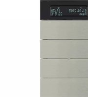
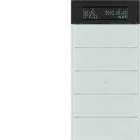
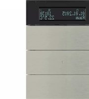
Glass sensor 2gang with room thermostat
Order No.: 7564 2x xx
Glass sensor 3gang with room thermostat
Order No.: 7564 3x xx
Operation- and
Assembly Instructions
1 Safety instructions
Electrical equipment may only be installed and fitted by electrically skilled persons.
Serious injuries, fire or property damage possible. Please read and follow manual fully.
Do not use any sharp objects, acids or organic solvents for cleaning. Device can be damaged.
Do not operate the device with sharp or pointed objects. The touch-sensitive surface could be damaged.
These instructions are an integral part of the product, and must remain with the end customer.
2 Device components

Figure 1
(1) Sensor buttons -/OK, +/Λ
(2) Sensor buttons for operating functions
(3) Status LED
(4) Operation LED
3 Function
System information
This device is a product of the KNX system and complies with the KNX directives. Detailed technical knowledge obtained in KNX training courses is a prerequisite to proper understanding.
The function of this device depends upon the software. Detailed information on loadable software and attainable functionality as well as the software itself can be obtained from the manufacturer's product database. Planning, installation and commissioning of the device are carried out with the aid of KNX-certified software. The latest versions of product database and the technical descriptions are available on our website.
Intended use
- Operation of loads, e.g. light on/off, dimming, blinds up/down, brightness values, temperatures, calling up and saving light scenes, etc.
- Touch sensor: Installation in double flush-mounted appliance box according to DIN 49073
- Glass sensor: Glass sensor TS: Installation in double installation socket for glass sensor (see chapter 6.3. Accessories)
Product characteristics
- The pushbutton functions switching, dimming, controlling blinds, value transmitter, calling up moods, etc.
- Operation through touching the sensor buttons
- LED to display status or actuation
- Integrated room temperature sensor
- Room temperature control with setpoint value specification
- Display of room and setpoint temperature
- Display of external temperature; in conjunction with external KNX temperature sensor
- Display of day and time, in conjunction with KNX time encoder
- Temperature limitation for floor heating; in conjunction with external temperature sensor
- Integrated bus coupling unit
4 Operation
The operation of functions or electrical consumers can be set individual for each device. Two operating modes are used:
- Single button operation: Switching on or off or dimming brighter/darker, e.g. of lighting, takes place alternately when the same sensor button is pressed repeatedly.
- Two button operation:
Two sensor buttons next to each other form a function pair. Pressing the left button, for example, switches or dims lighting on or brighter, pressing the right one switches it off or makes it darker.
Operating a function or load
Consumers such as lighting, blinds, etc. are operated using the sensor buttons (2) and such operation depends on the programming of the device.
■ Press a sensor button.
The stored function is executed.
The actuation pulse is relative to the length of touch. Depending on the function, short and long actuations may trigger different actions, e.g. switching/dimming.
Operating modes and display icons
The device compares the current room temperature with the setpoint temperature and controls heating or cooling devices according to the current demand. The setpoint temperature depends on the current operating mode and can be changed by the user, depending on the programming. The operating modes and the current controller status are shown in the display.

Figure 2
| Operating mode Comfort | |
| Operating mode Standby | |
| Operating mode Night | |
| Operating mode Frost/heat protection | |
| Display dewpoint operation; controller blocked | |
| Comfort extension, night | |
| Comfort extension, frost protection | |
| Setpoint value shift active | |
| Fan controller with fan level display | |
| Heating mode | |
| Cooling mode | |
| Icon blocked: buttons locked | |
| Interior temperature | |
| Outdoor temperature | |
| 1 ... 7 Weekdays Mon...Sun | |
| -and + Active when values are changed. | |
| OK and ^ Active, when the menu is active. |
The numeric display shows temperature values or times.
Basic display
Depending on the programming, the display can either be switched on permanently or for a specific time.

Figure 3
When switched on, the display shows, next to the icon for the current operating mode,
- the current time and day
- the current room temperature
- the current exterior temperature
- the current setpoint temperature
Changing the room temperature
For short-term manual modification of the setpoint temperature.

Figure 4
The basic display is visible.
■ Touch the left or right sensor button (1).
The display shows the current setpoint temperature.
■ Reduce setpoint temperature: press the left sensor button –.
- or -
■ Increase setpoint temperature: press the right sensor button +.
The setpoint temperature is adjusted in steps of 0.5 ^ .
The adjusted value is applied immediately.
The Ⓧ icon in the display shows that the setpoint temperature was adjusted.
The system returns to the basic display automatically after a specified time has elapsed or when any sensor button (2) is pressed.
i With appropriate programming, manual changes to the setpoint temperature is cancelled by changing the operating mode.
Displaying the main menu
From the main menu, it is possible to access additional functions for controlling and displaying the room temperature, e.g. cleaning function, operating mode switch, setting the setpoint temperatures (Figure 5).

flowchart
graph LR
    A["OK CL60"] --> B["OK +CC *"]
    B --> C["OK Pro °C"]
    C --> D["OK -2 Pro °C"]
    D --> E["→"]
    style A fill:#f9f,stroke:#333
    style B fill:#ccf,stroke:#333
    style C fill:#cfc,stroke:#333
    style D fill:#fcc,stroke:#333
    style E fill:#ffc,stroke:#333
Figure 5
The basic display is visible. The main menu is enabled.
- Press the + and – sensor buttons simultaneously.
The display shows the menu item CL60.
i Pressing the sensor button ∧ opens the additional menu items in sequence.
Setting the operating mode

flowchart
graph TD
    A["OK"] --> B["21.0°C"]
    B --> C["OK"]
    C --> D["19.0°C"]
    D --> E["OK"]
    E --> F["16.0°C"]
    F --> G["OK"]
    G --> H["7.0°C"]
    H --> I["OK"]
    I --> B
Figure 6
The main menu is displayed (Figure 5).
■ Using the sensor button , select the menu item Operating mode switch.
■ Press the OK sensor button.
The active operating mode is displayed with its setpoint temperature (Figure 6).
- Press the sensor button ^A to select the required operating mode.
■ Press the OK sensor button.
The setting is saved.
The display shows the new operating mode.
The setpoint temperature for the room is set according to the new operating mode.
Activating comfort extension
With automatic changeover of the operating modes, e.g. by an external timer, it is nevertheless possible to retain the comfort mode for some time. This is made possible by the comfort extension. Die Komfortverlängerung ist zeitlich begrenzt.
The device is in the operating mode Night or Frost/heat protection.
■ Actuate the Presence button on the device or other installed operating devices. The display shows the icons ⏻ or ⏻*.
The setpoint temperature for comfort mode is set for the set time.
Once the programmed time expires, the original operating mode Night or Frost/heat protection is restored.
i The comfort extension can also be activated automatically, e.g. via a presence sensor.
Change setpoint temperatures
For permanent setting of the setpoint temperatures for the Comfort, Standby and Night operating modes.
The main menu is displayed (Figure 5).

flowchart
graph TD
    A["OK"] --> B["Pro °C"]
    B --> C{OK}
    C --> D["21.0°C"]
    D --> E["OK"]
    E --> F["19.0°C"]
    F --> G{OK}
    G --> H["16.0°C"]
    H --> I{OK}
    I --> J["16.0°C"]
    J --> K["+"]
    K --> L["- & +"]
    L --> M["21.0°C"]
    M --> N["+"]
    N --> O["- & +"]
    O --> P["19.0°C"]
    P --> Q["+"]
    Q --> R["- & +"]
    R --> S["16.0°C"]
Figure 7
- Press the sensor button to select the menu item Pro for Heating mode ^+ or Cooling mode - and press the sensor button OK(Figure 7).
- Press the sensor button to select the required operating mode and press the OK sensor button.
The setpoint temperature flashes. - Reduce setpoint temperature: press the left sensor button – - or -
■ Increase setpoint temperature: press the right sensor button +.

Figure 8
■ Apply changes: press the + and - sensor buttons simultaneously.
The set setpoint temperature for the set operating mode is saved.
The display returns to the main menu.
- or -
■ Do not apply change: press another sensor button.
The device returns to the basic display.
i If the setpoint temperature should be changed for other operating modes, repeat the described operating levels.
Cleaning the device
The device can be blocked for 60 s to prevent unintentional actions from being executed when the glass is being cleaned.
The main menu is displayed.

flowchart
graph TD
    A["OK CL60"] --> B["↓ OK"]
    B --> C["CL59"]
    C --> D["..."]
    D --> E["CL00"]
Figure 9
- Press the sensor button to select menu item CL60 for the cleaning function and then press the sensor button OK(Figure 9).
All the functions on the device are blocked for 60 s.
All the status LEDs of the sensor buttons flash.
The display shows the time remaining until the end of the Cleaning function.
After 60 s, the device automatically reverts to the basic display, the lock is removed and normal operation possible.
i Cleaning with a lightly moistened, lint-free cloth, possibly with a mild glass cleaner. Do not use sharp objects or abrasive cleaning agents, e.g. scouring powder.
5 Information for electrically skilled persons

DANGER!
Electrical shock on contact with live parts in the installation environment. Electrical shocks can be fatal.
Before working on the device, disconnect the power supply and cover up live parts in the working environment.
5.1 Touch sensor with room thermostat
Mounting and connecting the Touch sensor

Figure 10
(5) Power supply connection
(6) Connection of wired floor temperature/remote sensors (accessories)
(7) KNX connection
(8) Programming LED
(9) Programming button
The device is installed by screwing the mounting frame to the appliance box or to the wall. Increased dismantling protection is achieved by securing the device on the bottom of the mounting frame using a retaining screw.
Use double flush-mounted box. Mounting on single flush-mounted boxes or surface-mounted boxes is not possible.
Bus voltage and an additional power supply are available at the installation location.
The yellow and white wire pair of the KNX bus line can be used to provide an additional power supply.
- Align the mounting frame (10) and screw it to the appliance box or the wall (Figure 11). Observe marking TOP = TOP. Use the enclosed set of screws.
■ Connect power supply to the terminal (5).
■ Connect the KNX bus voltage to the terminal (7).
■ Optional: Connect the external temperature sensor to the terminal (6).
i Programming button and LED are accessible only from the back of the device. If possible, load the physical address into the device before the final installation (see chapter 5.3. Commissioning).
■ Attach the device onto the mounting frame until it locks in place.
■ Tighten the retaining screw (11) on the bottom of the mounting frame. Use a Pozi-Drive screwdriver, size 0.

Figure 11
(10) Mounting frame
(11) Retaining screw
5.2 Glass sensor with room thermostat
Preparing the Glass sensor for mounting on a smooth substrate

Figure 12
(12) Adhesion points for adhesive dots
(13) Retaining peg
The adhesive dots prevent the glass sensor from slipping when mounted on smooth surfaces.
■ Free the adhesion points for the adhesive dots on the rear side of the glass sensor (12) from impurities.
■ Remove the adhesive dots from the carrier film and stick them to the four adhesion points.
■ Free the substrate of impurities.
■ Before mounting the glass sensor, remove the protective film from the adhesive dots.
Before completing mounting, align the glass sensor and press it in the area of the adhesive dots, in order to fix it in place.
Mounting and connecting the Glass sensor
Use the double installation socket (accessory). Mounting on single concealed sockets is not possible.
Optional: For increased dismantling protection or to increase the shadow gap to the wall, use the enclosed mounting frame (10). For this, lock the mounting frame onto the device from behind. Observe marking TOP = TOP.
Bus voltage and an additional power supply are available at the installation location.
The yellow and white wire pair of the KNX bus line can be used to provide an additional power supply.
If necessary, measure the surface compensation. With deeper installation sockets, adjusting the retaining pegs (14) on the threaded pins (15) allows a surface compensation of up to 20 mm. Unscrew the retaining pegs (14) by the surface compensation x, so that they are at a distance of 15 mm + x from the socket for the threaded pins
When the mounting frame is used, the distance for the surface compensation is 20 mm + x from the socket for the threaded pins.

Figure 13
(10) Mounting frame
(14) Retaining peg
(15) Threaded pin
(16) Friction spring
(17) Double installation socket (accessory)
■ Connect power supply to the terminal (5).
■ Connect the KNX bus voltage to the terminal (7).
■ Optional: Connect the external temperature sensor to the terminal (6).
Programming button and LED are accessible only from the back of the device. If possible, load the physical address into the device before the final installation (see chapter 5.3. Commissioning).
- Insert the device with the threaded pins (15) into the friction springs (16) of the appliance box (17) and push it in until the retaining pegs noticeably lock into place.
■ Align the device and push it in in the area of the retaining points to fix it.
Mounting the Glass sensor with increased dismantling protection
For increased dismantling protection, the mounting frame is firmly screwed to the appliance box or the wall and the device secured using a retaining screw on the bottom of the mounting frame.
■ Lever the friction spring seats (16) out of the appliance box, in order to reveal the screw holes of the installation socket.
- Align the mounting frame and screw it to the appliance box of the wall. Observe marking TOP = TOP. Use the enclosed set of screws.
■ Connect power supply to the terminal (5).
■ Connect the KNX bus voltage to the terminal (7).
■ Optional: Connect the external temperature sensor to the terminal (6).
Programming button and LED are accessible only from the back of the device. If possible, load the physical address into the device before the final installation (see chapter 5.3. Commissioning).
■ Attach the device onto the mounting frame until it locks in place.
- Tighten the retaining screw (11) on the bottom of the mounting frame. Use a Pozi-Drive screwdriver, size 0.

Figure 14
(18) Friction spring seat
Dismantling the Glass sensor
■ If available, slacken the retaining screw on the bottom edge. Use a Pozi-Drive screwdriver, size 0.
■ Press the enclosed dismantling too in the centre of the glass sensor.
■ Using the dismantling tool, pull the glass sensor evenly out of the anchoring - friction springs or mounting frame.
■ Disconnect the connection cables.
5.3 Commissioning
Loading the physical address and application software
Configuration and commissioning with ETS3.0d with Patch A or later.
The device is connected and ready for operation.
The rear side of the device must be accessible.
■ Press the Programming button (9).
The programming LED (8) shows the programming state red.
■ Assign physical address.
The programming LED goes out.
■ Write the physical address on the device label.
■ Load application software into the device.
6 Appendix
6.1 Technical data
KNX medium TP 1
Commissioning mode S-mode
Rated voltage KNX DC 21 ... 32 V SELV
Power consumption KNX typical 150 mW
Connection mode KNX Connection terminal
Ambient temperature -5 ... +45 °C
Storage/transport temperature -25 ... +70 °C
Power supply
Rated voltage DC 18 ... 32 V SELV
Power consumption max. 0.5 W
Internal clock
Resolution, clock 1 min
Rate deviation max. 8 min/day
Internal room temperature sensor
Measuring range 0°C ...+40°C ±1%
Resolution 0.1 K
6.2 Troubleshooting
Glass sensor does not lock in place
Retaining pegs on the threaded pins adjusted incorrectly.
Remeasure the adjustment of the retaining pegs and correct them as necessary.
Glass sensor moves on the wall
Smooth substrate provides insufficient hold.
Use the adhesive dots supplied for mounting.
Touch/Glass sensor cannot be removed
The device was mounted with increased dismantling protection.
Slacken the screw on the bottom of the mounting frame.
Touch/Glass sensor does not react to operation
Connection to the bus voltage is faulty or has incorrect polarity.
Check, and if necessary, correct the wiring, bus line and power supply.
Display remains dark
Bus or power supply is faulty or has incorrect polarity.
Check, and if necessary, correct the wiring, bus line and power supply.
Display switched to dark centrally.
Impossible to switch the operating mode using menu operation
It may be that an open window with a window contact or a presence detector prevents the switch.
Not possible to actuate the sensor buttons
Button lock active. Icon is ♦ shown.
Switch off the button lock.
The menu or submenu cannot be opened in the display
The corresponding functions are not enabled or not programmed.
Remove the locks.
Program the required functions.
Incorrect time is displayed
Incorrect time set on central clock.
Correct the time on the central clock.
The display shows --:-- rather than the time
Missing synchronisation from the central clock.
Check the central clock.
The device must receive the time from the central clock at least once every 24 hours.
6.3 Accessories
Wall box 2gang Order No. 1871
Floor temperature sensor/remote sensor Order No. 161
6.4 Warranty
We reserve the right to make technical and formal changes to the product in the interest of technical progress.
Our products are under guarantee within the scope of the statutory provisions.
If you have a warranty claim, please contact the point of sale or ship the device postage free with a description of the fault to the appropriate regional representative.

- Safety instructions
- Device components
- Function
- System information
- Intended use
- Product characteristics
- Operation
- Operating a function or load
- Operating modes and display icons
- Basic display
- Changing the room temperature
- Displaying the main menu
- Setting the operating mode
- Activating comfort extension
- Change setpoint temperatures
- Cleaning the device
- Information for electrically skilled persons
- DANGER!
- Touch sensor with room thermostat
- Glass sensor with room thermostat
- Mounting and connecting the Glass sensor
- Mounting the Glass sensor with increased dismantling protection
- Friction spring seat
- Dismantling the Glass sensor
- Commissioning
- Loading the physical address and application software
- Appendix
- Technical data
- Troubleshooting
- Glass sensor does not lock in place
- Glass sensor moves on the wall
- Touch/Glass sensor cannot be removed
- Touch/Glass sensor does not react to operation
- Display remains dark
- Impossible to switch the operating mode using menu operation
- Not possible to actuate the sensor buttons
- The menu or submenu cannot be opened in the display
- Incorrect time is displayed
- The display shows --:-- rather than the time
- Accessories
- Warranty
Brand : HAGER
Model : 75643030
Category : Thermostat