
75144034 - Touch switch HAGER - Free user manual and instructions
Find the device manual for free 75144034 HAGER in PDF.


| Product Type | KNX Touch/Glass Sensor (1-4 gang) with Bus Coupling Unit |
| Number of Gangs | 1, 2, 3, or 4 (depending on model) |
| Operation | Touch-sensitive sensor buttons with status and operation LEDs |
| Functions | Switching, dimming, blind control, value transmitter, scene recall, temperature measurement |
| KNX Medium | TP1 (Twisted Pair) |
| Rated Voltage | DC 21…32 V SELV (via KNX bus) |
| Current Consumption | Max. 12.5 mA |
| Connection | KNX connection terminal |
| Ambient Temperature | -5…+45 °C |
| Storage/Transport Temperature | -25…+70 °C |
| Internal Room Temperature Sensor | Measuring range 0…+40 °C, accuracy ±1%, resolution 0.1 K |
| Installation | Double flush-mounted box (touch sensor) or double installation socket (glass sensor); optional mounting frame for increased protection |
| Protection Class | IP20 (typical for indoor use) |
| Dimensions (approx.) | Standard European flush-mount size (approx. 55 x 55 mm for sensor unit) |
| Weight (approx.) | 100 g per unit |
| Housing Material | Glass front (glass sensor) or plastic with glass-like surface (touch sensor) |
| Cleaning | Use a lightly moistened, lint-free cloth; mild glass cleaner; avoid sharp objects and abrasive cleaners |
| Safety | Installation by skilled electricians only; disconnect power before working; do not operate with sharp objects |
| Commissioning | ETS3.0d (Patch A or later); assign physical address via programming button |
| Accessories | Wall box 2-gang (Order No. 1871); floor temperature sensor/remote sensor (Order No. 161) |
| Warranty | Statutory provisions apply; contact point of sale or regional representative for claims |
Frequently Asked Questions - 75144034 HAGER
User questions about 75144034 HAGER
0 question about this device. Answer the ones you know or ask your own.
Ask a new question about this device
Download the instructions for your Touch switch in PDF format for free! Find your manual 75144034 - HAGER and take your electronic device back in hand. On this page are published all the documents necessary for the use of your device. 75144034 by HAGER.
USER MANUAL 75144034 HAGER
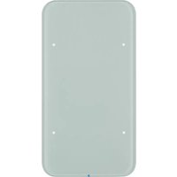
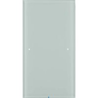
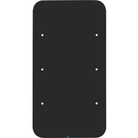
Touch/Glass sensor 1gang comfort with bus coupling unit Order No. : 7514 1x xx Touch/Glass sensor 2gang comfort with bus coupling unit Order No. : 7514 2x xx Touch/Glass sensor 3gang comfort with bus coupling unit Order No. : 7514 3x xx Touch/Glass sensor 4gang comfort with bus coupling unit Order No. : 7514 4x xx
Operation- and
Assembly Instructions
1 Safety instructions
Electrical equipment may only be installed and fitted by electrically skilled persons.
Failure to observe the instructions may cause damage to the device and result in fire and other hazards.
Do not operate the device with sharp or pointed objects. The touch-sensitive surface could be damaged.
Do not use sharp objects for cleaning. Do not use acids or organic solvents.
These instructions are an integral part of the product, and must remain with the end customer.
2 Device components

flowchart
graph TD
    A["Stage 1"] --> B["Node"]
    C["Stage 2"] --> D["Node"]
    E["Stage 3"] --> F["Node"]
    G["Stage 4"] --> H["Node"]
    style A fill:#999
    style C fill:#999
    style E fill:#999
    style G fill:#999
    style B fill:#ccc
    style D fill:#ccc
    style F fill:#ccc
    style H fill:#ccc
Figure 1
(1) User interface
(2) Sensor buttons for operating functions
(3) Status LED
(4) Operation LED
3 Function
System information
This device is a product of the KNX system and complies with the KNX directives. Detailed technical knowledge obtained in KNX training courses is a prerequisite to proper understanding.
The function of this device depends upon the software. Detailed information on loadable software and attainable functionality as well as the software itself can be obtained from the manufacturer's product database.
Planning, installation and commissioning of the device are carried out with the aid of KNX-certified software. Full functionality with KNX commissioning software version ETS3.0d onwards.
An updated version of the product database, technical descriptions and conversion programs and other auxiliary programs are available on our Internet website.
Intended use
- Operation of loads, e.g. light on/off, dimming, blinds up/down, brightness values, temperatures, calling up and saving light scenes, etc.
- Touch sensor: Installation in double flush-mounted appliance box according to DIN 49073
- Glass sensor: Installation in double installation socket for glass sensor (see chapter 6.3. Accessories)
Product characteristics
- The pushbutton functions switching, dimming, controlling blinds, value transmitter, calling up moods, etc.
- Operation through touching the sensor buttons
- LED to display status or actuation
- Integrated room temperature sensor for operation as controller extension
- Integrated bus coupling unit
4 Operation
The operation of functions or electrical consumers can be set individual for each device. Two operating modes are used:
- Single button operation: Switching on or off or dimming brighter/darker, e.g. of lighting, takes place alternately when the same sensor button is pressed repeatedly.
- Two button operation: Two sensor buttons next to each other form a function pair. Pressing the left button, for example, switches or dims lighting on or brighter, pressing the right one switches it off or makes it darker.
Operating a function or load
Consumers such as lighting, blinds, etc. are operated using the sensor buttons (2) and such operation depends on the programming of the device.
■ Press a sensor button.
The stored function is executed.
The actuation pulse is relative to the length of touch. Depending on the function, short and long actuations may trigger different actions, e.g. switching/dimming.
Cleaning the device
The device can be blocked for 60 s to prevent unintentional actions from being executed when the glass is being cleaned.
■ Recalling cleaning function by external telegram, e.g. from central
All the functions on the device are blocked for 60 s.
All the status LEDs of the sensor buttons flash.
i Cleaning with a lightly moistened, lint-free cloth, possibly with a mild glass cleaner. Do not use sharp objects or abrasive cleaning agents, e.g. scouring powder.
5 Information for electrically skilled persons

DANGER!
Electrical shock on contact with live parts in the installation environment.
Electrical shocks can be fatal.
Before working on the device, disconnect the power supply and cover up live parts in the working environment.
5.1 Touch sensor
Mounting and connecting the Touch sensor
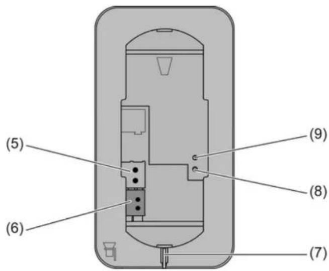
Figure 2
(5) Connection of wired floor temperature/remote sensors (accessories)
(6) KNX connection
(7) Fibre-optic cable for operation LED
(8) Programming LED
(9) Programming button
The device is installed by screwing the mounting frame to the appliance box or to the wall. Increased dismantling protection is achieved by securing the device on the bottom of the mounting frame using a retaining screw.
Use double flush-mounted box. Mounting on single flush-mounted boxes or surface-mounted boxes is not possible.
- Align the mounting frame (10) and screw it to the appliance box or the wall (Figure 3). Observe marking TOP = TOP. Use the enclosed set of screws.
■ Connect the KNX bus voltage to the terminal (6).
■ Optional: Connect the external temperature sensor to the terminal (5).
Programming button and LED are accessible only from the back of the device. If possible, load the physical address into the device before the final installation.
■ Attach the device onto the mounting frame until it locks in place.
■ Tighten the retaining screw (11) on the bottom of the mounting frame. Use a Pozi-Drive screwdriver, size 0.

Figure 3
(10) Mounting frame
(11) Retaining screw
5.2 Glass sensor
Preparing the Glass sensor for mounting on a smooth substrate

Figure 4
(12) Adhesion points for adhesive dots
(13) Retaining peg
The adhesive dots prevent the glass sensor from slipping when mounted on smooth surfaces.
■ Free the adhesion points for the adhesive dots on the rear side of the glass sensor (12) from impurities.
■ Remove the adhesive dots from the carrier film and stick them to the four adhesion points.
■ Free the substrate of impurities.
■ Before mounting the glass sensor, remove the protective film from the adhesive dots.
Before completing mounting, align the glass sensor and press it in the area of the adhesive dots, in order to fix it in place.
Mounting and connecting the Glass sensor
Use the double installation socket (accessory). Mounting on single concealed sockets is not possible.
Optional: For increased dismantling protection or to increase the shadow gap to the wall, use the enclosed mounting frame (10). For this, lock the mounting frame onto the device from behind. Observe marking TOP=TOP.
Bus voltage is available at the installation location.
If necessary, measure the surface compensation. With deeper installation sockets, adjusting the retaining pegs (14) on the threaded pins (15) allows a surface compensation of up to 20 mm. Unscrew the retaining pegs (14) by the surface compensation x, so that they are at a distance of 15 mm + x from the socket for the threaded pins.
When the mounting frame is used, the distance for the surface compensation is 20 mm + x from the socket for the threaded pins.

Figure 5
(10) Mounting frame
(14) Retaining peg
(15) Threaded pin
(16) Friction spring
(17) Appliance box (accessory)
■ Connect the KNX bus voltage to the terminal (6).
■ Optional: Connect the external temperature sensor to the terminal (5).
Programming button and LED are accessible only from the back of the device. If possible, load the physical address into the device before the final installation.
- Insert the device with the threaded pins (15) into the friction springs (16) of the appliance box (17) and push it in until the retaining pegs noticeably lock into place.
- Align the device and push it in in the area of the retaining points to fix it.
Mounting the Glass sensor with increased dismantling protection
For increased dismantling protection, the mounting frame is firmly screwed to the appliance box or the wall and the device secured using a retaining screw on the bottom of the mounting frame.
■ Lever the friction spring seats (16) out of the appliance box, in order to reveal the screw holes of the installation socket.
- Align the mounting frame and screw it to the appliance box of the wall. Observe marking TOP=TOP. Use the enclosed set of screws.
■ Connect the KNX bus voltage to the terminal (6).
■ Optional: Connect the external temperature sensor to the terminal (5).
Programming button and LED are accessible only from the back of the device. If possible, load the physical address into the device before the final installation.
■ Attach the device onto the mounting frame until it locks in place.
- Tighten the retaining screw (11) on the bottom of the mounting frame. Use a Pozi-Drive screwdriver, size 0.

Figure 6
(18) Friction spring seat
Dismantling the Glass sensor
■ If available, slacken the retaining screw on the bottom edge. Use a Pozi-Drive screwdriver, size 0.
■ Press the enclosed dismantling too in the centre of the glass sensor.
■ Using the dismantling tool, pull the glass sensor evenly out of the anchoring - friction springs or mounting frame.
■ Disconnect the connection cables.
5.3 Commissioning
Loading the physical address and application software
Configuration and commissioning with ETS3.0d with Patch A or later.
The device is connected and ready for operation.
The rear side of the device must be accessible.
■ Press the Programming button (9).
The programming LED (8) shows the programming state red.
■ Assign physical address.
The programming LED goes out.
■ Write the physical address on the device label.
■ Load application software into the device.
6 Appendix
6.1 Technical data
KNX medium TP 1
Commissioning mode S-mode
Rated voltage KNX DC 21 ... 32 V SELV
Current consumption KNX max. 12.5 mA
Connection mode KNX Connection terminal
Ambient temperature -5 ... +45 °C
Storage/transport temperature -25 ... +70 °C
Internal room temperature sensor
Measuring range 0°C ...+40°C ±1%
Resolution 0.1 K
6.2 Troubleshooting
Glass sensor does not lock in place
Retaining pegs on the threaded pins adjusted incorrectly.
Remeasure the adjustment of the retaining pegs and correct them as necessary.
Glass sensor moves on the wall
Smooth substrate provides insufficient hold.
Use the adhesive dots supplied for mounting.
Touch/Glass sensor cannot be removed
The device was mounted with increased dismantling protection.
Slacken the screw on the bottom of the mounting frame.
Touch/Glass sensor does not react to operation
Connection to the bus voltage is faulty or has incorrect polarity.
Check, and if necessary, correct the wiring, bus line and power supply.
6.3 Accessories
Wall box 2gang Order No. 1871
Floor temperature sensor/remote sensor Order No. 161
6.4 Warranty
We reserve the right to make technical and formal changes to the product in the interest of technical progress.
Our products are under guarantee within the scope of the statutory provisions.
If you have a warranty claim, please contact the point of sale or ship the device postage free with a description of the fault to the appropriate regional representative.

- Safety instructions
- Device components
- Function
- System information
- Intended use
- Product characteristics
- Operation
- Operating a function or load
- Cleaning the device
- Information for electrically skilled persons
- DANGER!
- Touch sensor
- Glass sensor
- Mounting and connecting the Glass sensor
- Mounting the Glass sensor with increased dismantling protection
- Friction spring seat
- Dismantling the Glass sensor
- Commissioning
- Loading the physical address and application software
- Appendix
- Technical data
- Troubleshooting
- Glass sensor does not lock in place
- Glass sensor moves on the wall
- Touch/Glass sensor cannot be removed
- Touch/Glass sensor does not react to operation
- Accessories
- Warranty
Brand : HAGER
Model : 75144034
Category : Touch switch