
CBS-2131XTS - Coffee maker Fetco - Free user manual and instructions
Find the device manual for free CBS-2131XTS Fetco in PDF.


| Product Type | Commercial Batch Coffee Brewer |
| Brand | Fetco |
| Model | CBS-2131XTS |
| Dimensions (W x D x H) | 17.5 x 19.5 x 28.5 inches (44.5 x 49.5 x 72.4 cm) |
| Weight | 40 lbs (18.1 kg) |
| Power Requirements | 120V, 60Hz, 15A, 1800W |
| Brewing Capacity | Two 1.9 L (64 oz) decanters |
| Brewing System | Dual satellite system with independent brewing heads |
| Control Type | Digital timer and programmable start/stop |
| Hot Water Faucet | Built-in, for tea or other hot beverages |
| Water Supply | Direct plumbed or optional external tank |
| Brew Pause Feature | Allows serving during brew cycle without overflow |
| Auto Shut-Off | Yes, adjustable after brew cycle |
| Maintenance Reminder | Clean cycle indicator and descaling alert |
| Cleaning Method | Brew-through cleaning cycle with recommended cleaner |
| Spare Parts Available | Decanters, brew baskets, heating elements, faucet assemblies |
| Warranty | One year parts and labor |
Frequently Asked Questions - CBS-2131XTS Fetco
User questions about CBS-2131XTS Fetco
0 question about this device. Answer the ones you know or ask your own.
Ask a new question about this device
Download the instructions for your Coffee maker in PDF format for free! Find your manual CBS-2131XTS - Fetco and take your electronic device back in hand. On this page are published all the documents necessary for the use of your device. CBS-2131XTS by Fetco.
USER MANUAL CBS-2131XTS Fetco
FETCO Extractor Touch Screen Models: CBS-2100XTS
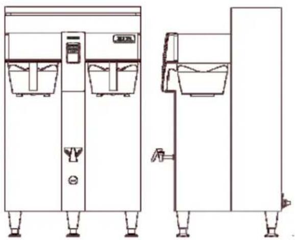
natural_image
Technical line drawing of two industrial water treatment machines with control panel and side-mounted buckets (no text or symbols)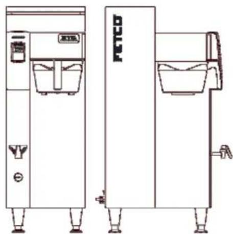
natural_image
Line drawing of two separate industrial water treatment machines, one with a water tank and the other with a water-filled basin (no text or symbols)Two Part User Guide FETCO Extractor Touch Screen Models: CBS-2100XTS
Extractor Touch Screen Commercial Hot Beverage Equipment
Table of Contents-
Part A: Universal CBS-2100 XTS Operation Instructions
First Brew....2
Instructions for brew operation-fast brew 2
Waiting Screens....3
Service & Programming......4
Programming menu layout ....5
Menu Features: Batch Parameters 6
How to calibrate the flow rate.... 10
Error Codes....12
Operator Training....13
Part B: Installation and Service Guide for FETCO CBS-2131 & CBS-2132XTS Brewers
Table of Contents: Installation and Service Guide Section—Reserved for qualified service technicians
Service Guide to a Successful Installation....2
Specifications and Requirements 3
Specifications-Electrical and Output 3
Parts diagrams 8
Wiring diagrams 18
Set-Up Instructions: 3 Liter.& 1 Galon configurations...22
Contact Information
FETCO®
Food Equipment Technologies Company
600 Rose Road
Lake Zurich • IL • 60047-0429 • USA
Internet: www.fetco.com
©2013-2016 Food Equipment Technologies Company
Phone: (800) 338-2699 (US & Canada)
(847) 719-3000
Fax: (847) 719-3001
Email: sales@fetco.com
techsupport@fetco.com
PATENTS: WWW.fetco.com/patents

P123
REV:002
March 2016
Instructions for brew operation-fast brew
Setup is simple
1-Connect unit to water and electrical utilities
See instructions
2-Turn unit "ON" to fill and heat
The "READY" icon will display "Ready To Brew" with factory set defaults
3-Add paper and ground coffee to brew basket
The Specialty Coffee Association of America® (SCAA) guidelines are 55grams per liter
4-Place appropriately sized, clean, empty and preheated dispenser under brewbasket.
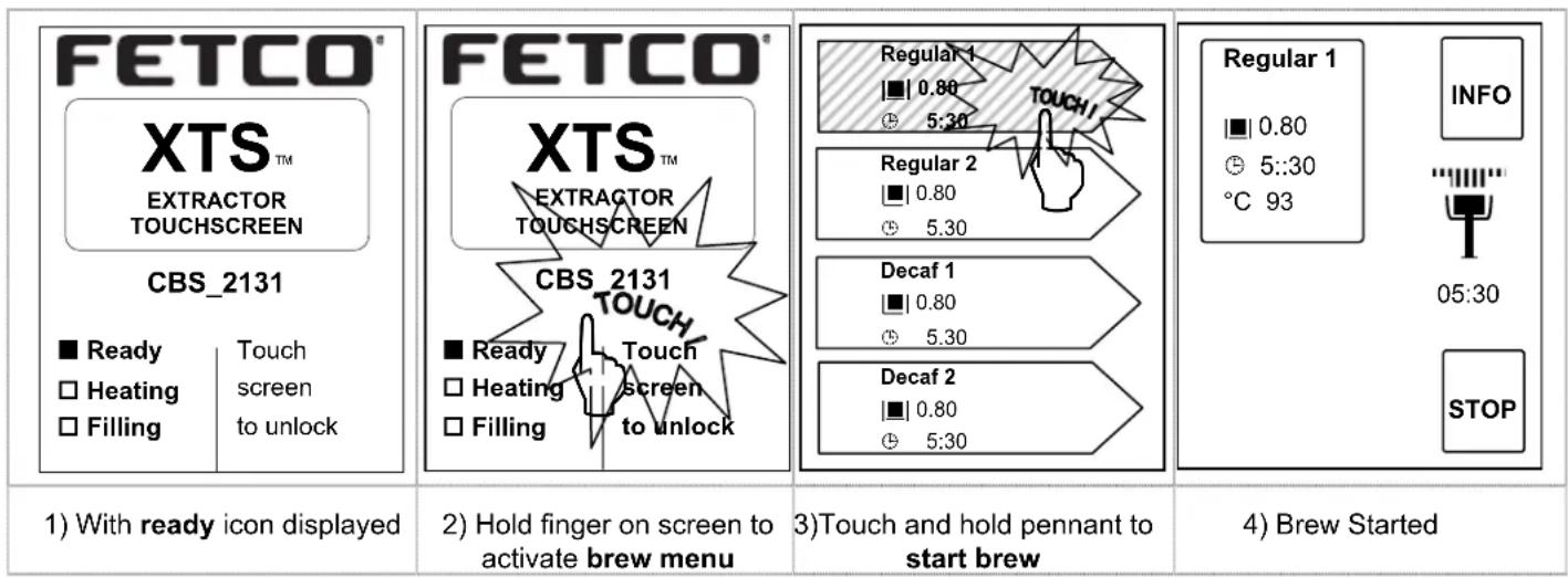
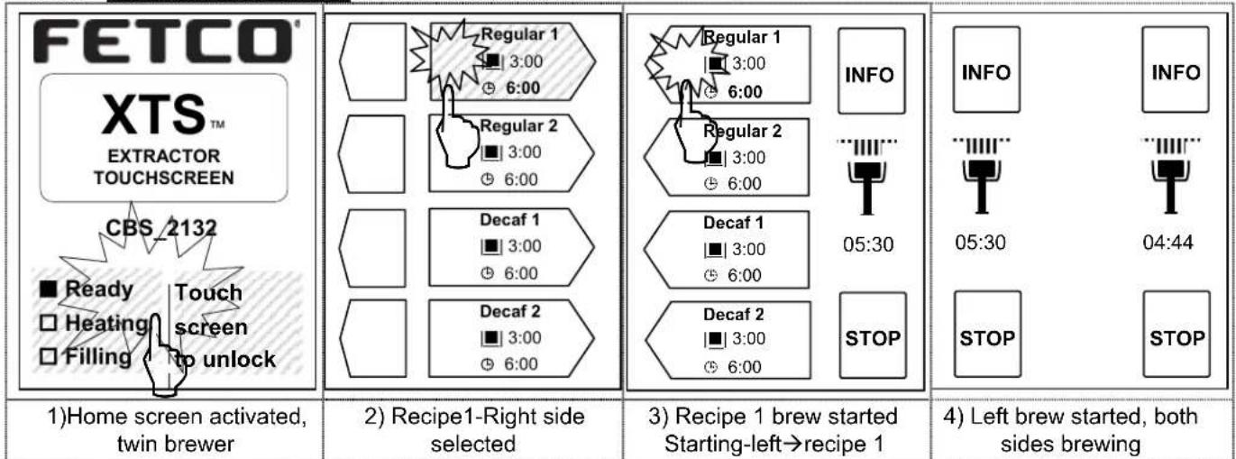
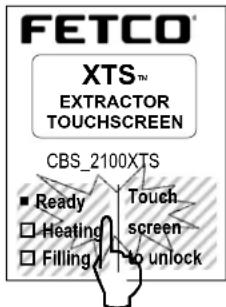
5-Touch and briefly hold finger on screen as shown below to start brew
-Note: "READY" icon is satisfied
Factory setting total brew time is five minutes-thirty seconds. Brew time is four minutes with one and a half minute drip delay. Drip delay allows the brew basket to completely empty the brewed coffee
Brew operation is simple. The intuitive touch screen-STARTS THE BREW
CBS-2131XTS single side brewer is displayed. Screen shown approximately the same size as on equipment
| Regular 1 ■ 0.80 ⊙ 5:30 °F 200 INFO 01:30 STOP | Regular 1 ■ 0.80 ⊙ 5:30 °F 200 INFO [ ] 01:29 | FETCO XTS™ EXTRACTOR TOUCHSCREEN CBS_2131 | |
| ■ Ready □ Heating □ Fillia | Touch screen to unlock | ||
| 5) Brew has completed, Drip delay sequence will start. Brew is still active | Drip delay icon (brew basket locked) | Return to home screen | |
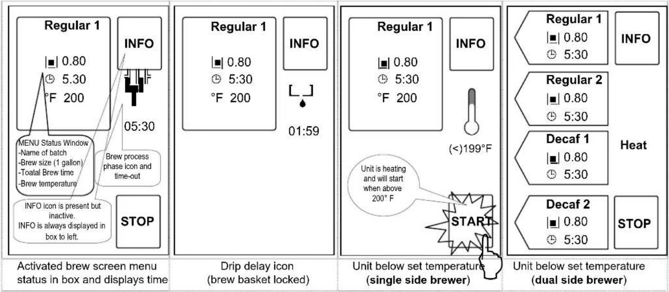
Brew operation-intuitive touch screen- When brew is started-the equipment displays the brew process graphically as shown Screens for dual brewer. CBS-2132XTS shown
Waiting Screens
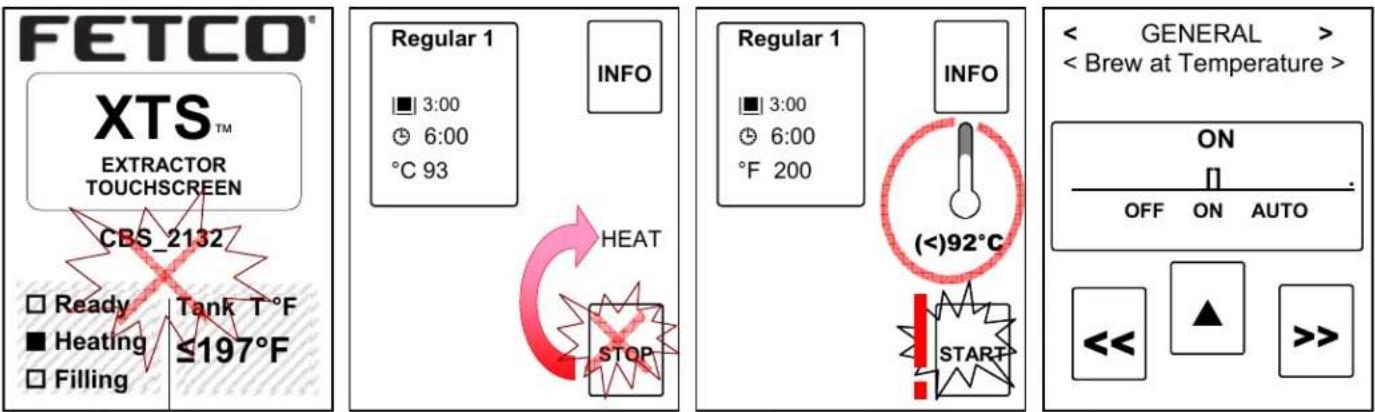
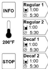
1) Hot water tank temp too low. Brew cannot start.
Note the :READY" icon is off & the "HEATING" icon is on. Brewer in "Automatic" temperature
2) Brew at Temperature feature is set to "AUTO" and hot water tank temperature is too low. Brew will start when tank is at set-point.
3) Brew at Temperature feature is "OFF" and hot water tank temperature is below set point. Pressing "START" will begin brew at low water temperature!
4) Programming screen for "Brew at Temperature" Unit is set by FETCO for "ON. "OFF and "AUTO" settings are not recommended
Service & Programming
Menu adjustments, name selection, programming, error codes, counters are accessed by activating touch screens.
To access the General Service Menu
PROGRAM, GENERAL, INPUTS, OUTPUTS, and OTHER (Service Menu).
→Enter Service Menu by accessing the power switch on back of the panel
1)-Switch power "OFF" with power switch located on rear of brewer
2)-After at least ten seconds: Turn power switch "ON"
3)-Quickly touch and hold the XTS screen to enter the programming screens as shown below
4)-When entering The SERVICE MENU: the first screen in the group is "PROGRAM"
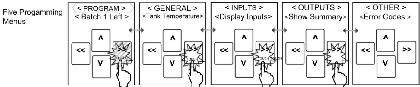
5)-Use right and left arrow icons to navigate through the five main SERVICE menu groups.
6)-The DOWN arrow navigation icon will open the FEATURE icon below.
6a)-Navigate through the Menu Item with the arrows, edit any if needed
6b)-When finished editing—press the UP arrow to go back through the menu items to save changes and exit
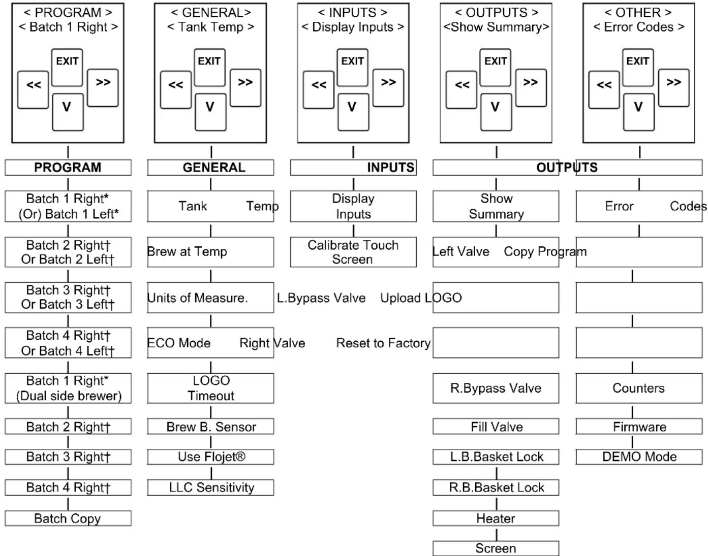
7)-The chart on the next page give the general service menu topics, the pages following list the details of the topics
→When navigating up to "EXIT" leaves the Service Menu Screens and SAVES your settings on exiting.
The Menu Chart on the next page shows the main categories of the five SERVICE menus
When SERVICE MENU is entered—the first selection is "PROGRAMMING Mode"
Scroll through the five programming categories using the right and left arrow icons.
flowchart
graph LR
    A["<PROGRAM> <Batch 1 Left>"] --> B["<GENERAL> <Tank Temperature>"]
    B --> C["<INPUTS> <Display Inputs>"]
    C --> D["<OUTPUTS> <Show Summary>"]
    D --> E["<OTHER> <Error Codes >"]

    subgraph Five Programming Menus
        A1["<<"] --> A2["Λ"]
        A2 --> A3["V"]
        A3 --> A4["TOUCH"]
        A4 --> A5["<<"]
    end

    subgraph Five Programming Menus
        B1["<<"] --> B2["Λ"]
        B2 --> B3["V"]
        B3 --> B4["TOUCH"]
        B4 --> B5["<<"]
    end

    subgraph Five Programming Menus
        C1["<<"] --> C2["Λ"]
        C2 --> C3["V"]
        C3 --> C4["TOUCH"]
        C4 --> C5["<<"]
    end

    subgraph Five Programming Menus
        D1["<<"] --> D2["Λ"]
        D2 --> D3["V"]
        D3 --> D4["TOUCH"]
        D4 --> D5["<<"]
    end

    subgraph Five Programming Menus
        E1["<<"] --> E2["Λ"]
        E2 --> E3["V"]
        E3 --> E4["TOUCH"]
        E4 --> E5["<<"]
    end
Use right and left arrow icons to navigate between the five main SERVICE menus
Navigating PROGRAMMING MENUES
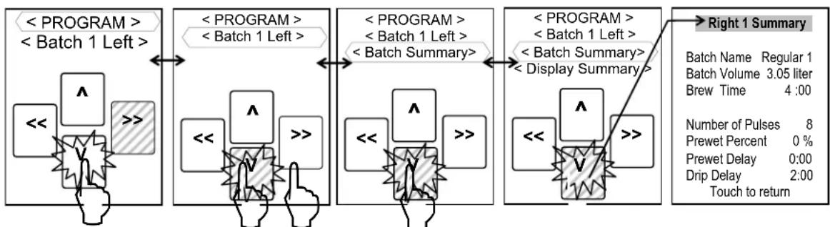
Highlight desired menu path and location and use arrow icons to navigate service menu screens. HIGHLIGHT
First menu screen is "PROGRAM"→ Note highlighted Path and Topic
flowchart
graph LR
    A["<PROGRAM> <Batch 1 Left>"] --> B["<PROGRAM> <Batch 1 Left>"]
    B --> C["<PROGRAM> <Batch 1 Left> <Batch Summary>"]
    C --> D["<PROGRAM> <Batch 1 Left> <Batch Summary> <Display Summary>"]
    D --> E["Right 1 Summary"]
    style A fill:#f9f,stroke:#333
    style B fill:#f9f,stroke:#333
    style C fill:#f9f,stroke:#333
    style D fill:#f9f,stroke:#333
    style E fill:#ccf,stroke:#333
Highlight programming path and use arrows to locate programming screen
Programming menu layout
XTS Main Menu
flowchart
graph TD
    A["<PROGRAM> <Batch 1 Right>"] --> B["PROGRAM"]
    B --> C["Batch 1 Right* (Or) Batch 1 Left*"]
    C --> D["Batch 2 Right† Or Batch 2 Left†"]
    D --> E["Batch 3 Right† Or Batch 3 Left†"]
    E --> F["Batch 4 Right† Or Batch 4 Left†"]
    F --> G["Batch 1 Right* (Dual side brewer)"]
    G --> H["Batch 2 Right†"]
    H --> I["Batch 3 Right†"]
    I --> J["Batch 4 Right†"]
    J --> K["Batch Copy"]

    L["<GENERAL> <Tank Temp>"] --> M["GENERAL"]
    M --> N["Tank Temp"]
    N --> O["Brew at Temp"]
    O --> P["Units of Measure."]
    P --> Q["ECO Mode Right Valve Reset to Factory"]
    Q --> R["LOGO Timeout"]
    R --> S["Brew B. Sensor"]
    S --> T["Use Flojet®"]
    T --> U["LLC Sensitivity"]

    V["<INPUTS> <Display Inputs>"] --> W["INPUTS"]
    W --> X["Display Inputs"]
    X --> Y["Calibrate Touch Screen"]

    Z["<OUTPUTS> <Show Summary>"] --> AA["OUTPUTS"]
    AA --> AB["Show Summary"]
    AB --> AC["Left Valve Copy Program"]

    AD["<OTHER> <Error Codes>"] --> AE["OUTPUTS"]
    AE --> AF["Error Codes"]

    AG["<PROGRAM> <Batch 1 Right>"] --> AH["EXIT"]
    AH --> AI["V"]
    AI --> AJ[">>"]

    AK["GENERAL"] --> AL["GENERAL"]
    AL --> AM["Tank Temp"]
    AM --> AN["Brew at Temp"]
    AN --> AO["Units of Measure."]
    AO --> AP["ECO Mode Right Valve Reset to Factory"]

    AQ["INPUTS"] --> AR["INPUTS"]
    AR --> AS["Display Inputs"]
    AS --> AT["Calibrate Touch Screen"]

    AU["OUTPUTS"] --> AV["OUTPUTS"]
    AV --> AW["Show Summary"]
    AW --> AX["Left Valve Copy Program"]

    AY["<PROGRAM> <Batch 1 Right>"] --> AZ["EXIT"]
    AZ --> BA["V"]
    BA --> BB[">>"]

    BC["GENERAL"] --> BD["INIT"]
    BD --> BE["Tank Temp"]
    BE --> BF["Brew at Temp"]
    BF --> BG["Units of Measure."]
    BG --> BH["ECO Mode Right Valve Reset to Factory"]

    BI["INPUTS"] --> BJ["INPUTS"]
    BJ --> BK["Tank Temp"]
    BK --> BL["Brew at Temp"]
    BL --> BM["Units of Measure."]

    BN["OUTPUTS"] --> BO["OUTPUTS"]
    BO --> BP["Error Codes"]

    BQ["<PROGRAM> <Batch 1 Right>"] --> BR["EXIT"]
    BR --> BS["V"]
    BS --> BT[">>"]

    BU["GENERAL"] --> BV["INIT"]
    BV --> BW["Tank Temp"]
    BW --> BX["Brew at Temp"]
    BX --> BY["Units of Measure."]
    BY --> BZ["ECO Mode Right Valve Reset to Factory"]

    CA["INPUTS"] --> CB["INIT"]
    CB --> CC["Tank Temp"]
    CC --> CD["Brew at Temp"]
    CD --> DD["Units of Measure."]

    BEQ["OUTPUTS"] --> BEQ
    BEQ --> BF
    BF --> BG
    BG --> BH
Menu Features: Batch Parameters
| PROGRAM | Programming Items | Factory set Default | Programming Range | Notes |
| Batch 1 LEFT* | • Batch Summary | Display Summary | Entire recipe display | Example at bottom of column |
| • Batch Name | Regular 1(-16) | Choose from list: Regular1 | (Regular 1-16)-OR-Write: any name | |
| Models CBS-2130, CBS-2140, CBS-2150 & CBS-2160XTS- | • Batch Volume | 0.80 to 3:00 gal | 3L/1gal -3.00 gal0.25-0.5gal 1.25-3.10gal | Screen will display in range and units selectedCBS-2160XTS is 3:00 gal |
| • Brew Time | 4:00mm:ss[2:00-10.00] | 4:00 mm:ss2:00-4.00 min 10:00 | CBS-2160XTS 4:30 min | |
| • Nr Of Pulses | 8 | 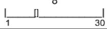 | CBS-2160 has minimum of 2 pulses | |
| • Prewet Perc. | 0% | 0% 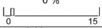 0:00 mm:ss 0:00 mm:ss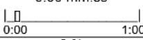 | This feature appears ONLY if Prewet >0:00 | |
| Pause after prewet completes | • Prewet Delay | 0% | ||
| • Bypass Perc. | 0% | 0% 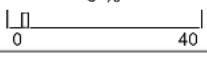 1:00 mm:ss 1:00 mm:ss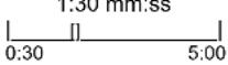 | ||
| This is a Safety Feature | • Drip Delay | 1:30 mm:ss2:00 mm:ss for CBS-2160 | Time that brew basket remains locked during final drip-out | |
| Batch 2 Left** | **[Batch 2-4-Right and Batch2-4-Left] may be individually selected-or-entirely deleted | |||
| • Batch ON/OFF | ON | 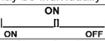 | This feature is only on 2-4 Batch 1 cannot be turned off | |
| • Batch Name | Regular 1(-16) | Choose from list: 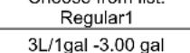 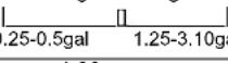 | (Regular 1-16)-OR-Write: any name | |
| Models CBS-2130, CBS-2140, CBS-2150 & CBS-2160XTS- | • Batch Volume | 0.80 to 3:00 gal | Screen will display in range and units selectedCBS-2160XTS is 3:00 gal | |
| • Brew Time | 4:00mm:ss[2:00-10.00] | 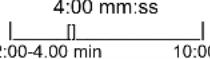 | CBS-2160XTS 4:30 min | |
| • Nr Of Pulses | 8 | 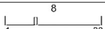 | CBS-2160 has minimum of 2 pulses | |
| • Prewet Perc. | 0% | 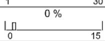 | ||
| Pause after prewet completes | • Prewet Delay | 0% | 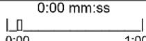 | This feature appears ONLY if Prewet >0:00 |
| • Bypass Perc. | 0% | 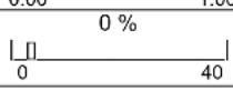 | ||
| This is a Safety Feature | • Drip Delay | 1:30 mm:ss2:00 mm:ss for CBS-2160 | 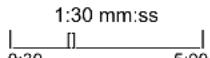 0.50 5.00 0.50 5.00 | Time brew basket remains locked during drip-out |
| Batch 3 Left ** | (See Batch 2-Left) | Batch 1 RightBatch Name Regular 1Batch Volume 3.00 galBrew Time 4:00Number of Pulses 8Prewet Percent 0 %Prewet Delay 0:00Drip Delay 1:30Touch to return (Example screen for Batch Summary display) | ||
| Batch 4 Left ** | (See Batch 2-Left) | |||
| Batch 1 Right * | (See Batch 1-Left) | |||
| Batch 2 Right ** | (See Batch 2-Left) | |||
| Batch 3 Right ** | (See Batch 2-Left) | |||
| Batch 4 Right ** | (See Batch 2-Left) | |||
| Batch Copy | Copy From Batch L1 | L1-L4;R1-R4 | ||
| Copy To Batch L1 L1 | L1-L4;R1-R4 | |||
| Copy? | L1→L2?(example) | NOYES NO | ||
| *Batch 1 RIGHT Side & Batch 1 LEFT Side cannot be disabled. (TWIN Brewer CBS-2102XTS)*Batch 1 cannot be disabled. (SINGLE Brewer)**Batch 2-4 can be disabled, and removed from display | ||||
Batch 1 Right
| GENERAL | Programming Items | Factory set Default | Programming Range | Notes |
| Tank Temp. | 200°F | 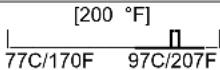 | Chart to correct for high altitude below | |
| “OFF” allows brewing at any temperature. | Brew at Temp. | “ON” | ON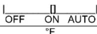 | SEE NOTE BELOW! |
| Units of Meas.Temperature | °C or °F | 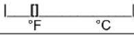 | [Switchable Units] | |
| Volume Gallons [Liters] | Gallons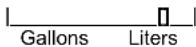 | [Switchable Units] | ||
| Energy Saving Mode | ECO Mode | OFF | 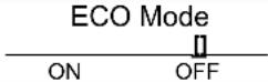 | If Selected: After 1 hour of inactivity→Lowers hot water tank temperature to 170°F |
| Logo Timeout | 0:15 mm:ss | 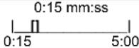 | ||
| This is a Safety Feature | Brew B. Sensor | NORMAL(SEE WARNINGS) | 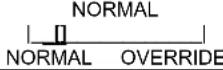 | Factory or service use for servicing. “NORMAL” is recommended for safety. |
| Use Flowjet | NO | 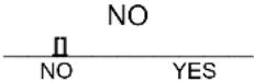 | Trims water handling system for Flowjet | |
| “NORMAL” for most water “HIGH” for R.O. | LLC Sensitivity | NORMAL | 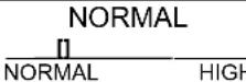 | Liquid level control sensitivity. High is for reverse osmosis water or very pure water. |
BREW AT TEMPERATURE DEFINITONS
BREW AT TEMP: "ON"
(DEFAULT: FACTORY PROGRAMMED INTO BREWER)
"BREW START" Batch Section Pennants will not be accessible until tank temperature is at set point.
The “BREW START” screens with the Batch Section Pennants become accessible when hot water tank is at the selected temperature. A screen (example to the right) will display and show “BREW AT TEMP” is selected. →
BREW AT TEMP: AUTO
USER SELECTABLE
"BREW START" will pause if the hot water tank is not at the selected temperature—and automatically start when it is at the set temperature.
If the temperature is too low, the brewer will wait until the proper temperature is reached. A screen (example to the right) will display showing a thermometer icon and the tank temperature→.
IMPORTANT: ALWAYS have dispenser(s) under the brewer when in the BREW AT TEMP mode
FETCO
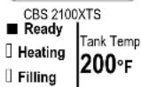
BREW AT TEMP: OFF
USER SELECTABLE
(Not recommended)
Allows brewing at any temperature above 170°F/82°C.
Chart to correct for altitude for boiling point in tank water temperature.
| [ft] | [m] | Suggested Setting[°F] | Boiling point[°F] | Suggested Setting[°C] | Boiling point [°C] |
| 0 | 0 | 205 | 212.0 | 96 | |
| 500 | 152 | 205 | 211.0 | 96 | 99.5 |
| 1000 | 305 | 200 | 210.1 | 93 | 98.9 |
| 2000 | 610 | 200 | 208.1 | 93 | 97.8 |
| 2500 | 762 | 200 | 207.2 | 93 | 97.3 |
| 3000 | 914 | 200 | 206.2 | 93 | 96.8 |
| 3500 | 1067 | 197 | 205.3 | 92 | 96.3 |
| 4000 | 1219 | 195 | 204.3 | 91 | 95.7 |
| 4500 | 1372 | 194 | 203.4 | 90 | 95.2 |
| 5000 | 1524 | 194 | 202.4 | 90 | 94.7 |
| 5500 | 1676 | 193 | 201.5 | 89 | 94.2 |
| 6000 | 1829 | 192 | 200.6 | 89 | 93.6 |
| 6500 | 1981 | 191 | 199.6 | 88 | 93.1 |
| 7000 | 2134 | 190 | 198.7 | 87 | 92.6 |
| 7500 | 2286 | 188 | 197.8 | 86 | 92.1 |
| 8000 | 2438 | 187 | 196.9 | 86 | 91.6 |
| 8500 | 2591 | 185 | 196.0 | 85 | 91.1 |
ECO MODE-Energy saving mode DEFINITONS
If Selected: Turns heaters off after 1 hour of inactivity.
The hot water tank temperature will slowly decline to no lower than 60°C/170°F
A screen (example to the right) will display showing "ECO Mode" is activated. →
To return from ECO-Mode
Tap the screen, ECO Mode turns off, and the brewer will heat to set temperature.
It takes approximately 7-15 minutes to return from 60^ / 170^ to factory default 93^ / 200^
All FETCO commercial hot beverage equipment have well insulated hot water tanks and have engineered mechanical features to limit energy consumption.
Effective construction and insulation increases equipment life and lowers building HVAC costs.
FETCO hot beverage equipment have the best energy savings of all major suppliers.
FETCO
XTS™
EXTRACTOR
TOUCHSCREEN
CBS 2100XTS
ECO
□ Heating
Filling
Tank Temp
170 °F
| INPUTS | Programming Items | Factory set Default | Programming Range (display) | Notes |
| Display Inputs | • Input Summery | R. Brew Basket Sens. □L. Brew Basket Sens. ■H. Liquid Level probe □L. Liquid Level probe ■Tank Temperature Probe ■SD Card Recognized ■Tank Temp. 93°C □ | ||
| Cal. Touch Scr | Calibrate | Calibrate YES NO | If Yes:Follow directions on the touch screen |
| INPUT SUMMARY SCREEN | |
| Display Inputs(See “INPUTS”Service Screen) | Brew Basket Sensor■High Liquid Level Probe□Low Liquid Level Probe■Tank Temp. Probe■SD Card present□Tank Temperature93C |
| Use DISPLY INPUTS screen to assist in error code fault correction.There are two liquid level probes shown as High and Low High is thefill volume of the hot water tank Low probe is the level when theheaters are sufficiently covered by water to start. | |
| OUTPUTS | Programming Items | Factory set Default | Programming Range (display) | Notes |
| Show Summary | Output Summary | Left Brew FR 3200Left Bypass FR 2400Right Brew FR 3200Right Bypass FR 2400Screen Contrast 8Screen Brightness 8Touch To Return | FR=Flow Rate ml/min | |
| Left ValveTest OR Calibrate | Left Valve Test (Press to test) | TESTPress To Test TEST | Runs valve to verify flow. Have container under brew-basket! | |
| ” ” ” ” | L. Valve Calib | Calibrate*Flow Rate | 1540 to 3200 ml p m1400-2800 1950-3800 | Factory or service use for flow rate adjustment |
| L. Bypass ValveTest OR CalibrateIf bypass option available | Left BypassValve Test | (Press to test) | TESTPress To Test TEST | Runs valve to verify flow. Have container under brew-basket! |
| ” ” ” ” | L. Bypass ValveCalib | Calibrate*Flow Rate | 2150 to 2400 ml p m1900-2100 2800 | Factory or service use for flow rate adjustment |
| Left Valve display is only for CBS-2102XTS dual side brewer. CBS-2101XTS Single series displays RIGHT SIDE only | ||||
| Right ValveTest OR Calibrate | Right Valve Test (Press to test) | TESTPress To Test TEST | Runs Valve to verify flow. Have container under brew-basket! | |
| ” ” ” ” | R. Valve Calib | Calibrate*Flow Rate | 1540 to 3200 ml p m1400-2800 1950-3800 | Factory or service use for flow rate |
| R. Bypass ValveTest OR CalibrateIf bypass option available | Right BypassValve Test | (Press to test) | TESTPress To Test TEST | Runs valve to verify flow. Have container under brew-basket! |
| ” ” ” ” | R. BypassValve Calib | Calibrate*Flow Rate | 2150 to 2400 ml p m1900-2100 2800 | Factory or service use for flow rate adjustment |
| Fill Valve | Fill Valve Test (Press to test) | TESTPress To Test TEST | Operates fill valve. Have container under both brew-baskets! | |
| Left Basket Lk.Not on CBS 2130XTS | Left brew basketlock test | (Press to test) | TESTPress To Test TEST | Energizes brew basket lock. For factory or service use |
| Right Basket Lk.Not on CBS 2130XTS | Right brewbasket lock test | (Press to test) | TESTPress To Test TEST | Energizes brew basket lock. For factory or service use |
| Heater | Heater Test (Press to test) | TESTPress To Test TEST | Energizes Heater(s) Service use only. | |
| ScreenBrightness OR Contrast | Screen Contrast Contrast | 81 10 | ||
| S. Brightness | Brightness | 81 10 | ||
| Default-factory set Flow Rates; Brew Valve and Bypass See “OUTPUTS” right and left brew valve and bypass valve settings and calibration | |||
| CBS-2152 & CBS-2162 ml/min | CBS-2151& CBS-2161ml/min | ||
| Left Brew FR | 3200 | Right Brew FR | 3200 |
| Left Bypass FR | 2400 | Right Bypass FR | 2400 |
| Right Brew FR | 3200 | ||
| Right Bypass FR | 2400 | ||
| CBS-2132& CBS-2142 ml/min | CBS-2131&CBS-2141 ml/min | ||
| Left Brew FR | 1540 | Right Brew FR * | 1540 |
| Left Bypass FR* | 2150 | Right Bypass FR* | |
| 2150 | |||
| Right Brew FR* | 1540 | ||
| Right Bypass FR | 2150 | ||
How to calibrate the flow rate
Set the flow rates of components to adjust for taste profile and for over or under potting.
Built-in algorithms in Brewer controller software corrects brew parameter to customer preferences or to trim variations in flow control components
NOTICE: This operation requires operator hold finger on keypad position for one minute—without lifting it.
1) MEASURE THE FLOW RATE:
It is very important to calibrate a heated brewer, preferably a brewer that has been used for brewing.
-Enter programming mode, scroll left to "OUTPUTS"
-Scroll down to "Left(or)Right Valve Test"
-Place 5 liter/2gal measuring container under empty brew-basket.
One good way to measure is to weigh the test water. Use a scale for at least 5 kg/12lb
-Press To Test the Brew Valve. → ! Keep finger on touchpad for one minute! !!DO NOT STOP!!
It is very important for this test to keep finger in place for the entire minute.
After one minute [1 min.]—calibration dispense will stop automatically.
Measure the results of the flow in the 5-liter measuring container and hold the number.
2) AUTOMATIC Built-in CALIBRATE THE FLOW RATE
-Enter this number, in milliliters, into the calibration slider for the Valve tested in the OUTPUT MENU.
- Use millilitersasured in fluid ounces (fl.oz) multiply by 29.57 to convert to milliliters
-After entering the measured volume, exit PROGRAMMING and return to the normal screens
3) MANUAL METHOD Operator input: CALIBRATE THE FLOW RATE
Use the amount measured, in milliliters, divided by programmed value and multiply by the current setting
| 3200 ml p m* | ← Example ofCBS-2160 brewvalve slider | Actual VolumeProgrammed VolumeX | CURRENTSETTING | = NEWSETTING | Enter new setting on theslider shown and EXIT tosave | |
| 2800 | 3800 | |||||
*Current valve flow setting in milliliters per minute [mlpm] as shown in the value above slider in OUTPUT Flow Rate box-Obtain programmed volume from "PROGRAM" Menu under "Batch Summary".
Note—match correct batch number to correct side, if two sided.
By entering the new flow rate number into the brewer, the software automatically corrects the valve flow discrepancy
| Default-factory set Flow Rates; Brew Valve and BypassSee "OUTPUTS" right and left brew valve and bypass valve settings and calibration | |||
| CBS-2162 | ml/min | CBS-2161 | ml/min |
| Left Brew FR 3200 | Right Brew FR 3200 | ||
| Left Bypass FR 2400 | Right Bypass FR 2400 | ||
| Right Brew FR 3200 | |||
| Right Bypass FR 2400 | |||
| CBS-2152 | ml/mirCBS-2151 | ml/min | |
| Left Brew FR 3200 | Right Brew FR 3200 | ||
| Left Bypass FR 2400 | Right Bypass FR 2400 | ||
| Right Brew FR 3200 | |||
| Right Bypass FR 2400 | |||
| CBS-2142 | ml/mirCBS-2141 | ml/min | |
| Left Brew FR 1540 | Right Brew FR 1540 | ||
| Left Bypass FR 2150 | Right Bypass FR 2150 | ||
| Right Brew FR 1540 | |||
| Right Bypass FR 2150 | |||
| CBS-2130XTS equipment do not have the BYPASS featureCBS-2132 | ml/mirCBS-2131 | ml/min | |
| Left Brew FR 1540 | Right Brew FR 1540 | ||
| Right Brew FR 1540 | |||
| OTHER | Programming Items | Factory set Default | Programming Range (display) | Notes |
| Error Codes | • Display Errors (Codes) | 1:2:3: | See Error Code Chart for references | |
| • Reset Errors | (Reset) | 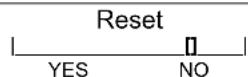 | Factory and Service use only. Do Not Reset | |
| NOTE Clear error codes by cycleing the brewer “OFF” then “ON”. Do not reset the error codes. Resetting error codes should be after completing the service and factory diagnostics and correcting any brewer faults | ||||
| Copy Program | • From SD to B. | SD→ Brewer | 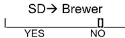 | Setup uploadPlease insert SD card with the setup data! |
| • From B to SD | Brewer→ SD | 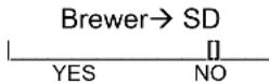 | Setup download Please insert an empty SD card with sufficient space (≤2GB). SD card must be clear of files | |
| Upload Logo | Upload Logo | 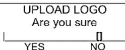 | Please insert SD card with logo file! | |
| Res to Factory & Select Brewer Type | See next line:“Select Brewer Configuration” | Reset to default | Reset to DefaultAre you sure | Completely overwrites all user setup, incl. user logo. |
| Select Brewer Configuration | CBS_2131 3L; CBS_2131 1G CBS_2132 3L; CBS_2132 1G CBS_2141; CBS_2142 CBS_2151; CBS_2152 &2152-2G CBS_2161; CBS_2162 | Screen appears after pressing “Resto Factory” [Above] | 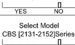 | Scroll to your brewer and tap ENTER tab |
| Counters | • Display Counters -OR-• Display Resettable Counters | Counters Display Total Counters | 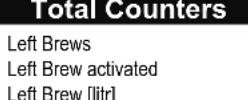 Left Bypass activated Left Bypass activated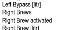 Right Bypass activated Right Bypass activated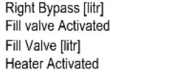 Heater “ON” timeTouch To Return Heater “ON” timeTouch To Return | Identical screen for Resettable CountersWill display when selected. See next line to reset to zeroNOTE:“Total Counters” is not user resettableSee table, next page, for counter screen, definitions |
| Reset Counters | • Resets Counters | Reset All Counters | 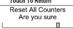 YES NO YES NO | Resetting will restart counter from zero |
| Firmware | • Firmware Version-Software type | Display Firmware Version | CBS_2132 for model type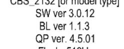 Flash=512KD Flash=512KD | Displays firmware version |
| • Update Firmware | UPDATE | UPDATE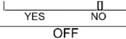 | Firmware uploadPlease insert SD card with the firmware file! | |
| DEMO Mode | DEMO ON/OFF | ON OFF | Demonstrates the controls for training. Disables all components in demo mode. | |
| COUNTER Screen, Definition | ||
| Total brews on left side Left Brews 13 | ||
| Actual brews on left side Left Brew activated 13 | ||
| Total volume produced by left side brewer Left Brew [litr] 39 | ||
| Actual Bypass used on left side Left Bypass activated 0 | ||
| Total volume of left bypass Left Bypass [litr] 0 | ||
| Total brews on right side Right Brews 41 | ||
| Actual brews on right side Right Brew activated 41 | ||
| Total volume produced by right side brewer Right Brew [litr] 0 | ||
| Actual Bypass used on right side | Right Bypass activated | 0 |
| Total volume of right bypass | Right Bypass [litr] | 0 |
| Total cycles activated by fill valve | Fill valve Activated | 0 |
| Total cycles activated by fill valve | Fill Valve [litr] | 0 |
| Total heater cycles activated | Heater Activated | 0 |
| Total time heater has been energized | Heater “ON” time | 0:00 |
| Touch To Return | ||
| Error Codes | ||||
| →Contact specialized personnel for error codes | ||||
| Code | Description | Possible Cause | Corrective Action | How to Clear Error Codes |
| 001 | Software error-error on start up or corrupted software | Improper start-up or shutdown | Restart, if still fault: reload software | TO CLEAR FAULT, Make repairs as requiredBelow is the only way to clear error codes:1) Enter“PROGRAMMING”2)Scroll left to “OTHER”3)Scroll down to “ERROR CODES”4)Scroll down to “Display Errors”5)Scroll left to “Reset Errors”6)Scroll down to “Reset”7)Follow directions shown on screen.Merely toggling ON/OFF switchwill notclear error codes.Error codes must be cleared by correcting the fault and entering PROGRAMMING and using the menus! |
| 050 | Short-circuit in temperature probe | Probe failure. | Replace probe. | |
| 051 | Open temperature probe. | Bad probe connection, or probe failure. | Check all connections. Replace probe if necessary. | |
| 100 | Initial Fill Error. Initial fill time was more than 11 minutes after power up. | Water supply flow rate is too low. | Watch for short potting during brew cycle.Investigate cause of low flow rate. (Clogged water filter...) | |
| 101 | Error on refillTank did not refill within 3 minutes. | Water supply flow rate is too low. | Watch for short potting during brew cycle.Investigate cause of low flow rate. (Clogged water filter...) | |
| 102 | Unwanted fill; | Possible leak in tank, fitting, or valve. | Occurs during pre-fill, low probe is uncovered | |
| 107 | FaultLower liquid level probe | Tank not filling | Occurs during pre-fill, low probe is uncovered, or wires are reversed low / high probe | |
| 201 | Heater open, high limit thermostat, or Solid State Relay (SSR) fault | Failure of: heating element, SSR, high Limit or low voltage | Check and replace heating elements if necessary. | |
| 255 | Touch pad error | Usually from longer than 2 min contact.Or faulty reassembly after service | Restart, if still fault: reload software. If mechanical: reassemble correctly | |
| INSERTBREW BASKET | Brew basket must be in placeThis is a SAFETY FEATURE | Insert brew basket into brewer rails to enable brewer | ||
! → Never attempt to defeat or override a brew basket-locking feature-this is a safety feature
Operator Training
Review the operating procedures with whoever will be using the brewer.
Pay particular attention to the following areas:
- Always pre-heat the dispensers before the first use of each day by filling them half way with hot water, and letting them stand for at least 5 minutes.
- Do not remove the brew basket from a coffee brewer until it has stopped dripping.
- Make sure the dispenser is empty before brewing into it.
- Show how to attach covers, close, and or secure the dispensers for transporting.
- Show the location and operation of the water shut off valve as well as the circuit breaker for the brewer.
- Steam from the tank will form condensation in the vent tubes. This condensation will drip into and then out of the brew baskets. Up to 1/4 cup/118cc discharging overnight is possible. Place an appropriate container under each brew basket when not in use.
- We recommend leaving the power to the brewer on overnight. The water tank is well insulated and very little electricity is used to keep the tank hot. Leaving the brewer in the "ON" position will also avoid delays at the beginning of shifts for the brewer to reach operating temperature.
Cleaning
&
Maintenance
After Each Brew:
- Dispose of grounds and rinse brew basket.
- Never strike a brewbasket or hit it against a hard surface. This will damage the brew cone, and may damage the brewbasket support rails
- Rinse dispensers before reuse.
Every Day:
- Wash brew basket with hot sudsy water.
- Pull CSD from the spray head, it is magnetically attached. Use gloves or a heavy towel. → Wash off any film and reattach. Use vinegar if limescale filming is present.
- Clean dispensers with hot suds water and a brush, rinse and air dry.
- Use only a soft cloth and hot suds on the outside to avoid scratches. Never use abrasives that will scratch surface.
Weekly
- Use a commercial coffee dispenser cleaner such as URNEX™, TABZ™, DIP-IT™ or Squeak 'n Clean™.
- Carefully Follow the instructions supplied with the cleaning product
- Never use spray cleaners, solvent, solvent based cleaner or petroleum based polish anywhere on dispensers
Warning
- Turn off power before any cleaning procedure, including wiping the exterior for appearance reasons.
- Dry the exterior, especially the face panel, before turning on power.
- Do not apply any type of spray cleaner on the face panel of this equipment.
- Never use solvent or solvent-based cleaner or petroleum based polish anywhere on this equipment.
- Dry the face of the touch pad before turning on power
- Do not electrically energize this equipment or attempt operation without all covers in place and all screws fastened.
- Unplug machine before disassembly or servicing.
Safety Notes
- Professional installation is required. This appliance is manufactured only for commercial use
- Operational requirements and maintenance for commercial cooking appliances differ from household appliances.
- Operators must be trained for this equipment and must understand the use, maintenance and hazards.
- Access to the service area is restricted to persons having safety/hygiene knowledge and practical experience of the coffee brewer. This appliance must be installed in locations where it can be overseen by adult trained personnel.
- Do not attempt to move hot beverage equipment once it is filled. Drain equipment before moving.
- FETCO commercial coffee brewers prepare large amounts of coffee or tea in a single batch using very hot water
- Commercial coffee brewers provides very hot water from the sprayhead, brewbasket and faucet when it is pulled.
- Coffee brewers may continue to dispense very hot water from the mechanically operated faucet after the electronic touchpad is completely disabled by turning off the power switch on the lower back of the unit, or unplugging the unit.
- For safety, the brewer control locks the brew basket for 5.5 minutes after starting the brew.
- Never attempt to defeat the factory set (default) time that the brew basket is locked for safety from start of brew.
Keep these instructions for training and future reference.
natural_image
Technical line drawing of a mechanical component with a central hub and concentric rings (no text or symbols)
END OF SECTION NOTES
Models:
CBS-2130XTS
Extractor Touch Screen Commercial Hot Beverage Equipment
FETCO Touch Screen Models: CBS-2130XTS
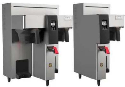
Airport and dispenser series:
CBS-2131 3 liter CBS-2132 3 liter CBS-2131 1 gallon airport CBS-2132 1 gallon airport CBS-2131& CBS-2132 1 gallon dispenser
natural_image
Two industrial water treatment machines with control panels and red valves, shown from different angles (no visible text or labels)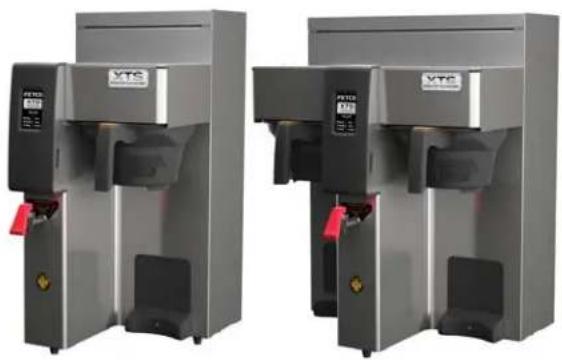
natural_image
Two identical industrial machines with VTS branding and red clamps, shown from different angles (no visible text or symbols on the devices themselves)Table of Contents: Installation and Service Guide Section—Reserved for qualified service technicians
Service Guide to a Successful Installation....2
Specifications and Requirements .... 3
Specifications-Electrical and Output 3
Parts diagrams ....8
Wiring diagrams 18
Set-Up Instructions: 3 Liter.& 1 Galon configurations...22
Contact Information
FETCO®
Food Equipment Technologies Company
600 Rose Road
Lake Zurich • IL • 60047-0429 • USA
Internet: www.fetco.com
©2013-2016 Food Equipment Technologies Company
PATENTS: WWW.fetco.com/patents
Phone: (800) 338-2699 (US & Canada)
(847) 719-3000
Fax: (847) 719-3001
Email: sales@fetco.com
techsupport@fetco.com
P123 part B REV002
March 2016
Service Guide to a Successful Installation
(For Qualified Service Technicians Only)
General:
- If not installed correctly by qualified personnel, the brewer will not operate properly and damage may result
- Select and install appropriate legs for 3-liter or 1-gallon setup. Leg sets are shipped inside the brew basket
- Some FETCO CBS-2100XTS series equipment have user configurable dispenser locator-see instructions.
- Utilize only qualified beverage equipment service technicians for service and installation.
- Always have an empty dispenser under sprayhead of all coffee brewing equipment-including when at idle
- Damages resulting from improper installation are not covered by the warranty, and will void the warranty. Below are the key points to consider before installation:
Electrical:
- All CBS_Series brewers require an electrical ground wire. Installation without grounding is dangerous.
- Note Equipotentiality Terminal, if present, (To identify the terminals which, when connected together, bring the various parts of equipment or of a system to the same potential, not necessarily being the earth (ground) potential, e.g. for local bonding.)
- Verify voltages, polarity, circuits, and circuit breaker access before attaching equipment.
- Brewers in this series wire differently in regards to a nuatral wire. Review the wire diagrams.
- The electrical diagram is located in the Users Guide and online at www.fetco.com.
- Make sure of the tight grounding of the equipment and use the external ground bolt.
- The installation must comply with applicable federal, state, and local codes having jurisdiction at your location. Check with your local inspectors to determine what codes will apply.
→See wiring diagrams for connections
Plumbing:
- North America: All installations must comply with applicable federal, state, or local plumbing codes.
- All Others: The water and waste piping and connections shall comply with the International Plumbing Code 2003, International Code Council (ICC), or to the Uniform Plumbing Code 2003 (IAPMO).
- Use an inline water filter for all beverage equipment.
- Install the filter unit after a water shutoff valve and in a position to facilitate filter replacement.
- The water line and newly installed filter cartage must be flushed thoroughly prior to connecting it to the brewer to prevent debris from contaminating the machine.
- Verify that the water line will provide a flow rate of at least 112 gpm/(5.7lpm) per minute and the water pressure is between 20-75 psig (138-517kPa) before making any connections.
- Use a wrench on the factory fitting when connecting the incoming water line. This will reduce stress on the internal connections and reduce the possibility of leaks developing after the install has been completed
- Install a backflow prevention device. Most municipalities require a recognized backflow preventer.
- Usable on all hot beverage and cold beverage equipment is a WATTS® SD-2 or SD-3.
- WATTS spring loaded double check valve models are accepted by most zoning authorities. →The check valve should be as close to the water supply inlet of the beverage equipment as possible.
Tank Drain
The water tank must be drained before maintenance procedures, and when the unit is to be relocated or shipped
- Disconnect power to unit.
-
Move the unit near a sink or obtain a container large enough to hold four gallons of water and a hose clamp. Note that the tank may hold more than four gallons and that the drain line will be clamped to empty the container.
-
Remove the tank cover and allow the tank to cool to a safe temperature
-
The tank drain is located on the back of the unit. Turn the drain plug one-quarter turn in either direction
-
Pull the plug out far enough to expose the silicone tube
-
Using pliers loosen the hose clamp and move it back over the tube.
-
Crimp the tube an inch or two away from the drain plug to prevent water from flowing.
-
Use the other hand to pull the drain plug out of the tube.
-
Release the crimped tube and allow the water to flow into the sink or container.
-
Multiple buckets may be needed during the draining, see tank volumes below.
| Brewer Hot Water | Tank Capacity |
| CBS-2131 Single 3 | .5 gal 13.2 liter |
| CBS-2132Twin 6.4 | gal 24 liter |
Specifications and Requirements
Water Requirements:
CBS-2130XTS: 20-75 psig, (138-517kPa) 1½gpm/(5.7lpm)
Water supplied to hot beverage equipment should be filtered
Water supplied Hardness >100 TDS (5.5 grain)
Water inlet fitting is a 3/8 inch male flare.
Brew Volume: Full Batch Up to 1 gallon/3.8 liters per brew
Total Brew Cycle—Factory setting: 5.5 minutes=[4 minute brew time + 1.5 minute drip delay]
Coffee Filter Size:
13" X 5"" - standard FETCO # F002
Electrical: See electrical configuration chart.
Temperature, as set by factory:
200°F (93°C) inside water tank (at sea level)
Specifications-Electrical and Output Configurations
For qualified service technicians
| These specifications apply to FETCO CBS-2131XTS & CBS-2132XTS manufactured as of January 2016 | ||||||||
| CBS-2130XTS USA and Canada | ||||||||
| CBS_2131XTS—Single Single-Voltage Cord and Plug/Two wire electrical | ||||||||
| Configuration Codes | Heater Configuration | Voltage | Phase | Wires | Electrical Connection | KW | Amp Draw | Brew-Volume/Hour (3 liters per batch) |
| E213153 | 1 X 1.5 kW | 100 - 120 | 1 | 2+G | NEMA 5-15P | 1.6 | 13.0 | 3.9 gal/14.8 liters |
| E213151 | 1 X 2.3 kW | 100 - 120 | 1 | 2+G | NEMA 5-20P | 2.4 | 19.7 | 5.8 gal/22 liters |
| E213157 | 1 X 3.0 kW | 200 - 240 | 1 | 2+G | NEMA 6-15P | 3.1 | 13.0 | 7.7 gal/29.1 liters |
| CBS_2132XTS—Twin Single-Voltage | ||||||||
| Configuration Code | Heater Configuration | Voltage | Phase | Wires | Electrical Connection | KW | Amp Draw | Brew-Volume/Hour (3 liters per batch) |
| E213251 | 2 X 2.3 kW | 200-240 | 1 | 2+G | Terminal Block | 4.7 | 19.7 | 11.5 gal/43.5 |
| E213252 | 2 X 3.0 kW | 200-240 | 1 | 2+G | Terminal Block | 6.1 | 25.5 | 14.0 gal/53 liters |
| Please see wiring diagrams located in back pages for installation notes. | ||||||||
| CBS_2131XTS—Single Field configurable, Dual-Voltage Three wire plus ground electrical | ||||||||
| Configuration Codes | Heater Configuration | Voltage | Phase | Wires | Electrical Connection | KW | Amp Draw | Brew-Volume/Hour (3 liters per batch) |
| E213172 1 X 1.7 kW | 120 | 1 | 2+G | NEMA 5-15P | 1.8 | 14.7 | 4.4 gal/16.7 liter | |
| (*Optional) | 2 X 1.7 kW (120/208-240) | 1 | (3+G) | Hardwire L1,L2,N+G | 3.5 | 14.7 | 8.7 gal/33 liter | |
| E213173 1 X 2.3 kW | 120 | 1 | 2+G | NEMA 5-20P | 2.4 | 19.7 | 5.8 gal/22 liter | |
| (*Optional) | 2X 2.3 kW (120/208-240) | 1 | (3+G) | Hardwire L1,L2,N+G | 4.7 | 19.7 | 11.0gal/41.6 liter | |
| *Sold with factory cord & plug for 120 Volt configuration. Optional user connection to a terminal block requiring L1, L2, N and ground to120/208-240 VACUser selectable for optional, dual in-series heater configuration: DO NOT WIRE L2 to nuetral. The optional configuration requires three wire plus ground. | ||||||||
SEE WIRING DIAGRAMS AT BACK OF THIS GUIDE
| CBS-2131XTS From Factory120 volt models | CBS-2131XTS *Field installed Option120/208-240 volt models | (one)CBS-2131XTS and(all)CBS-2132XTS200-240 volt L1, L2,G models |
| All CBS 2131XTS | OPTIONAL 2 HEATER ONLY | |
| SKU E213151; E213153SKU E213172; E213173 | SKU E213172; E213173 | SKU E213157; (single).SKU E213251 E213252 (dual) |
CBS-2131XTS Single Brewer-Technical Data Capacities & Measurements 3 liter&1 gallon single brewers
| Brewer | Height | Width | Depth | Empty Weight | Filled Weight | Total Weight-Brewer & Filled Dispenser | Hot Water Tank Capacity | Shipping Weight | Shipping Dimensions |
| CBS-2131XTS Single-3 liter | 26 1⁄4" 666mm | 11 3⁄4" 303mm | 20 3⁄8" 516mm | 29 lb 13.2kg | 55 lb 25 kg | 66.2lb 34.6 kg | 3.3 gal 12.4 l | 49 lb 19 kg | 17" x 23" x 29" 432 x584x737mm |
| CBS-2131XTS Single-1 gallon | 27 3⁄4" 704mm | 11 3⁄4" 303mm | 20 3⁄8" 516mm | 29 lb 13.2kg | 55 lb 25 kg | 66.2lb 34.6 kg | 3.3 gal 12.4 l | 49 lb 19 kg | 17" x 23" x 29" 432 x584x 737mm |
CBS-2131XTS SINGLE, three liter setup
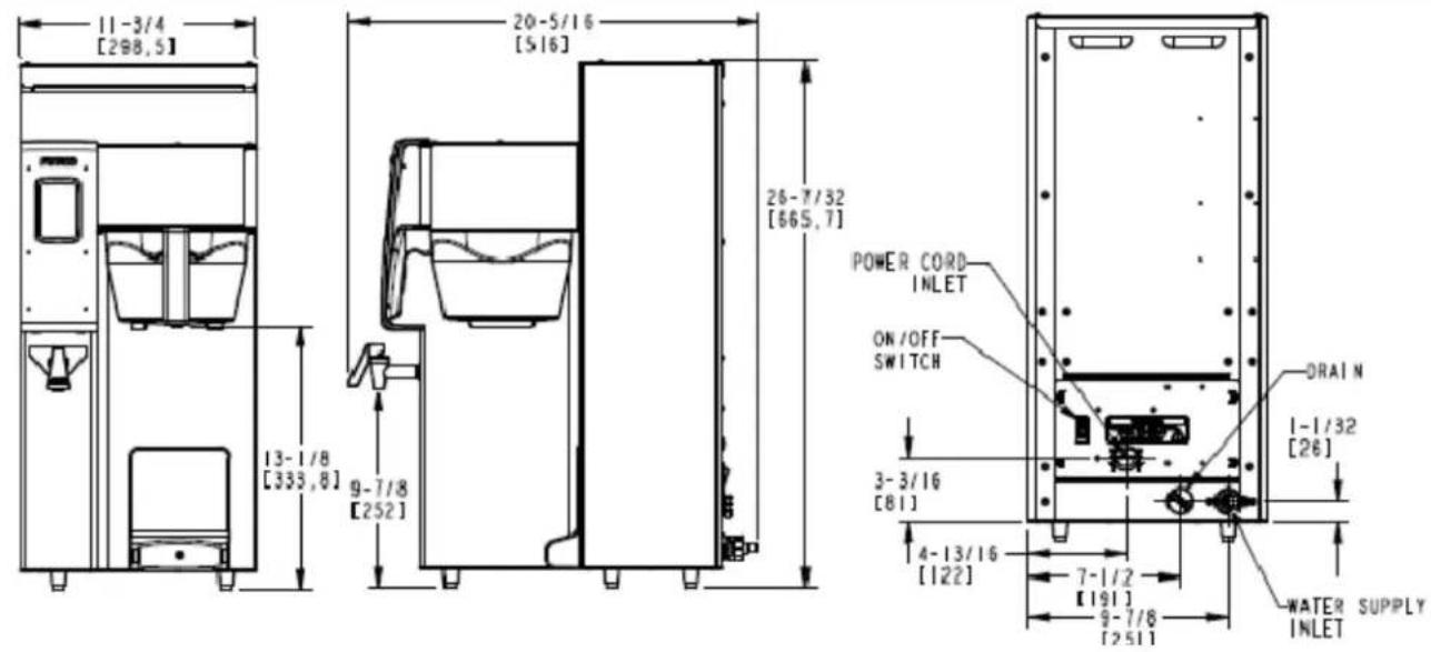
CBS-2131XTS SINGLE, one gallon setup
![11-3/4 [298,5] 13-1/8 [333,6]](/content/2026/05/839100/images/8ddcfe35f6981d969c05428e31b505744413c20cfea23eb8d250b0e81f6663ad.jpg)
![20-5/16 [5-16] 26-7/32 [665,7] 9-7/8 [252]](/content/2026/05/839100/images/eeffa17aef026056d19499047b939593b0ac4017e6edf3b175d0df6e30fb7e65.jpg)
![POWER CORD INLET ON/OFF SWITCH 3-3/16 [81] 4-13/16 [122] 7-1/2 [191] 9-7/8 [2511] DRAIN 1-1/32 [26] WATER SUPPLY INLET](/content/2026/05/839100/images/b91f7c38eb3ea33f995e8c56c87e8b0633a30abad464049e332d8f5e7774ecdf.jpg)
CBS-2132XTS TWIN-Technical Data
Capacities & Measurements 3 liter&1 gallon dual brewers
| Brewer | Height | Width | Depth | Empty Weight | Filled Weight | Total Weight-Brewer & Filled Dispenser | Hot Water Tank Capacity | Shipping Weight | Shipping Dimensions |
| CBS-2132XTS Dual-3 liter | 2618" 666mm | 1934" 502mm | 2038" 518mm | 47lb21.3kg | 92lb41.7kg | 114.4lb51.9 kg | 5.8 gal22.1 l | 61lb28kg | 23"x25"x29" 584x635x737mm |
| CBS-2132XTS Dual-1 gallon | 2734" 704mm | 1934" 502mm | 2038" 518mm | 47lb21.3kg | 92lb41.7kg | 114.4lb51.9 kg | 5.8 gal22.1 l | 61lb28kg | 23"x25"x29" 5584x635x737mm |
CBS-2132XTS TWIN, three liter setup
![19-3/4 [501,7] 13-1/8 [333,8]](/content/2026/05/839100/images/4a6ccd12073b743184e147e66653a443ceda0eab1efa6193ead820c7e3c9a086.jpg)
![20-5/16 [516] 9-7/8 [252] 26-7/32 [665, 7]](/content/2026/05/839100/images/251e1e19bd72494e4d80df88a47daaf1d521c5b75bcfd0c2ecec910fdae1da99.jpg)
![POWER CORD INLET ON/OFF SWITCH 3-3/16 [81] 4-13/16 [122] 7-1/2 [191] 9-7/8 [251] WATER SUPPLY INLET DRAIN 1-1/16 [26]](/content/2026/05/839100/images/263f2ccc976bb1c5f65c7a3647f0bd504cd87461d56c3f7e5d19cf82dc30a114.jpg)
CBS-2132XTS TWIN, one gallon setup
![19-3/4 [501,73] 14-5/8 [371,9]](/content/2026/05/839100/images/2289ae987736b818e890ec27a5bb5f10bf8a4985798cbba2526f32d58bd8ce53.jpg)
![20-5/16 [516] 27-23/32 [703,8] 11-3/8 [290]](/content/2026/05/839100/images/d7dd084d6f56502aee8a2cd55c72d36e2bce04b0210d1fc0dda52720aeeb9012.jpg)
![POWER CORD INLET ON/OFF SWITCH 3-5/16 [81] 4-13/16 [122] 7-1/2 [191] 9-7/8 [251] WATER SUPPLY INLET DRAIN 1-1/16 [26]](/content/2026/05/839100/images/b408b5f187b7d3b806a773eb05bf9a9ad23697b21380833a6f8bc4b690c2c5de.jpg)
Installation safety and hygiene directions-For International and CE equipment
- Access to the service area is restricted to persons having safety/hygiene knowledge and practical experience of the coffee brewer. This appliance must be installed in locations where it can be overseen by trained personnel.
- For proper operation, this appliance must be installed indoors where the temperature is between 10°C/50°F to 35°C/95°F. Drain and remove all liquid from equipment and lines if exposed to freezing temperatures.
- All commercial cooking equipment, including this unit, is not intended for use by children or persons with reduced physical, sensory, or mental capabilities. Ensure proper supervision of children and keep them away from the unit.
- Children should be supervised to ensure that they do not play hot beverage equipment.
- This unit must be installed and serviced by qualified personnel only.
- Installation must conform to all local electrical and plumbing codes. Installation by unqualified personnel will void the unit warranty and may lead to electric shock or burn, as well as damage to unit and/or its surroundings.
- If the power cord requires repair or replacement-it must be performed by the manufacturer or authorized service personnel with the specified cord only from the manufacturer in order to avoid a hazard.
- Review the dimensions for the unit and verify that it will fit properly in the space intended for it. Verify that the counter or table will support the total weight of the brewer and dispensers when filled (See: Technical Data).
- Place the brewer on the counter or stand. When the brewer is in position, level it front to back as well as side-to-side by adjusting the legs.
- Brewers will need a sturdy supported surface for operation. Do not move brewers when filled.
- Do not tilt appliance more than 10^ to insure safe operation.
- Unit is for protected indoor use only. Do not steam clean or use excessive water on unit.
- This unit is not "jet-proof" construction. Do not pressure wash or use jet spray to clean this unit.
- The unit is not waterproof-do not submerge or saturate with water.
Equipment exposed to flood and contaminated must not be used due to electrical and food safety. Do not operate if unit has been submerged or saturated with water.
All electrical connections must be in accordance with local electrical codes and any other applicable codes. If the supply cord is damaged, it must be replaced by the manufacturer, its service agent, or similarly qualified persons in order to avoid a hazard.
To prevent an electric shock hazard this device must be bonded to equipment in close proximity with an equipotential bonding conductor. This device is equipped with a bonding lug for this purpose and is marked with the following symbol

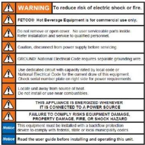
Labels and warnings for hot beverage equipment
For BACK PANEL of equipment (1046.00035.00)
| 1102.00203.00 Spray Housing Assembly Parts CBS-2130XTS | |||||
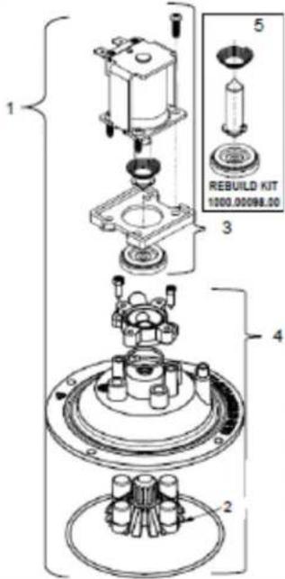 | Ref. | QTY | PART NO DESCRIPTION | ||
| 1 | 1 | Complete Spray Housing | |||
| 2 | 1 | 1102.00019.00 Replacement, Cascade Spray Dome | |||
| 3 | 1 | #3 Contained in KIT 1000.00097.00 | VALVE DIAPHRAGM | ||
| 3 | 1 | ADAPTER PLATE, SPACER | |||
| 3 | 1 | PLUNGER, DISPENSE VALVE 24VDC | |||
| 3 | 1 | SPRING, DISPENSE VALVE 24VDC | |||
| 3 | 1 | COIL AND FRAME ASSEMBLY DSV11 24VDC | |||
| 3 | 4 | SCREW, #6-20 X 1/2", PHIL | |||
| 4 | 1 | #4 Contained in KIT 1000.00096.00 | SPRAY HOUSING ASSY CSD DESIGN | ||
| 4 | 1 | O-RING, AS568A-019, BUNA-N | |||
| 4 | 1 | 1102.00019.00 | ASSEMBLY, CASCADE SPRAY DOME | ||
| 4 | 1 | ADAPTER, SPRAY HSG, DSV11 VALVE | |||
| 4 | 2 | SCREW, M3.9x13, CHEESE PH | |||
| 4 | 1 | 1024.00063.00 | O-RING, Lower 3 15/16" x 3/32" | ||
| 5 | Valve rebuild kit 1000.00098.00 | Kit contains: SPRING DIAPHRAGM PLUNGER | |||
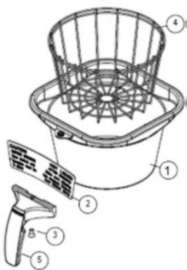
| Brew Basket Parts | |
| Complete Plastic Brew Basket (STANDARD) | |
| Part Number B014218BN2 CBS-2130XTS | |
Brown colored insertis standard→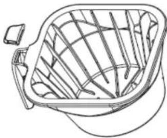 Brew basket handle plugfor polymeric brewbaskets is available inoptional colors. Brew basket handle plugfor polymeric brewbaskets is available inoptional colors. | Part Number Plug Insert color |
| 1023.00195.00 BROWN PLUG, BB HANDLE | |
| 1023.00194.00 BLACK PLUG, BB HANDLE | |
| 1023.00190.00 RED PLUG, BB HANDLE | |
| 1023.00191.00 GREEN PLUG, BB HANDLE | |
| 1023.00192.00 ORANGE PLUG, BB HANDLE | |
| 1023.00180.00 BLUE PLUG, BB HANDLE | |
Parts diagrams
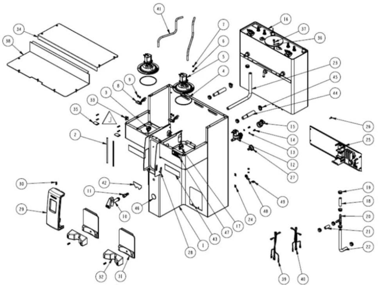
CBS-2131XTS
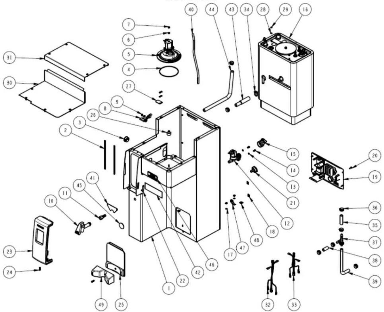
Parts Drawing CBS-2131 XTS Drawing number 1101.00151.00
| Parts Drawing CBS-2131 XTS Drawing number 1101.00151.00 | |||
| Ref | Qty Part Number | Part Name | and Description |
| 1 | 1 | 1111.00036.00 WELDMENT BODY, COMPLETE, CBS-2131 | |
| 2 | 2 | 1024.00049.00 EDGE PROTECTOR, 7.00"LG, CBS-2130 | |
| 3 | 1 | 1086.00004.00 BUSHING, NAP, 1" MOUNTING HOLE | |
| 4 | 1 | 1024.00063.00 O-RING, 3 15/16" x 3/32" CS, DASH # 154, BUNA-N, DURO-A50 | |
| 5 | 1 | 1102.00203.00 ASSEMBLY | SPRAY HOUSING, DSVP11 DESIGN |
| 6 | 4 | 1083.00010.00 WASHER, #10 SCREW W/NEOPRENE-BONDED SEAL | |
| 7 | 9 | 1084.00006.00 NUT, 8-32 18-8 HEX MACHINE SCREW | |
| 8 | 1 | 1102.00113.00 SWITCH, REED, ASSEMBLY | |
| 9 | 2 | 1029.00006.00 #4-40 NYLON FINGER NUT | |
| 10 | 1 | 1071.00010.00 FAUCET HPSC-BR-8 REGULAR HANDLE | |
| 11 | 1 | 1031.00003.00 FITTING, BARB 3/8"ID x 1/4" FPT | |
| 12 | 1 | 1057.00043.00 SOLENOID VALVE, SINGLE, 180 DEG, 240VDC | |
| 13 | 2 | 1083.00005.00 WASHER, M4 18-8 INTERNAL TOOTH LOCKWASHER | |
| 14 | 2 | 1082.00010.00 SCREW, M4x10 ZINC PLATED PAN PHILLIPS MACHINE | |
| 15 | 1 | 1102.00243.00 ADAPTER ASSY, 3/4" BSP x 1/4" NPT x 3/8" TUBE | |
| 16 | 1 | 1104.00082.00 TANK ASSY,1 X 2.3kW/120VAC, | |
| 16 | 1 | 1104.00083.00 TANK ASSY,1 X 1.5kW/120VAC, | |
| 16 | 1 | 1104.00086.00 TANK ASSY,1 X 3.0kW/240VAC | |
| 16 | 1 | 1104.00070.00 TANK ASSY, 2 X 1.7kW/120VAC | |
| 16 | 1 | 1104.00066.00 TANK ASSY, 2 X 2.3kW/120VAC | |
| 17 | 5 | 1083.00011.00 WASHER, #8 SCREW SIZE, INTERNAL TOOTH LOCK | |
| 18 | 1 | 1084.00011.00 NUT, CLIP ON (J-NUT), #6-32, 22-20 GA., BLK-PH FINISH | |
| 19 | 1 | 1102.00209.00 ASSEMBLY BACK PANEL, CBS-2131 AND 2141 | |
| 20 | 12 | 1082.00017.00 SCREW, # 6-32 X 1/2" TRUSS HD PHIL., MACHINE | |
| 21 | 1 | 1023.00147.00 PLUG, TANK SERVICE DRAIN FOR 18GA AND UP BODY | |
| 22 | 1 | 1024.00040.00 CARD PLUG, HWD-2100 | |
| 23 | 1 | 1102.00210.00 ASSEMBLY FRONT PANEL, CBS-2130 | |
| 24 | 5 | 1082.00058.00 SCREW, # 8-32 X 5/8, FLAT HD, PH, 18-8 SS | |
| 25 | 1 | 1102.00259.00 LOCATOR ASSEMBLY,L3S-10, GRAY, CBS-2130 | |
| 26 | 1 | 1023.00159.00 CORNER INSERT | |
| 27 | 1 | 1003.00259.00 BRACKET, BREW BASKET LOCK COVER | |
| 28 | 3 | 1083.00009.00 WASHER, #6 SCREW, INTL TOOTH LOCKWASHER | |
| 29 | 3 | 1084.00010.00 NUT, HEX, #6-32, UNDERSIZED, ZINC PLATED | |
| 30 | 1 | 1001.00126.00 COVER, UPPER BASE, CBS-2131 AND 2141 | |
| 31 | 1 | 1001.00125.00 COVER, TOP CBS-2131 AND 2141 | |
| 32 | 1 | 1402.00039.00 HARNESS, HIGH AMP, CBS-2131 | |
| 33 | 1 | 1402.00040.00 HARNESS, LOW AMP, CBS-2131 | |
| 34 | 1 | 1086.00002.00 CLAMP, HOSE, SIZE "G" NYLON | |
| 35 | 1 | 1025.00060.00 TUBE, 9/16"OD X 5/16"ID X 3.25"LG | |
| 36 | 8 | 1086.00003.00 UNICLAMP, 15.9 HOSE OD CLAMP | |
| 37 | 1 | 1029.00002.00 FITTING, HOSE BARB TEE, SIZE 3/8", NYLON | |
| 38 | 1 | 1025.00058.00 TUBE, 9/16"OD X 5/16"ID X 25.00"LG | |
| 39 | 1 | 1025.00077.00 TUBE, 9/16 OD x 5/16 ID x 6.50 LG. | |
| 40 | 1 | 1025.00078.00 TUBE, 5/16 OD x 3/16 ID x 14.00 LG. | |
| 41 | 1 | 1046.00006.00 LABEL, WARNING, "HOT WATER FAUCET" | |
| 42 | 1 | 1046.00003.00 LABEL, CSD WARNING, 1.5" X 5.0" | |
| 43 | 1 | 1024.00065.00 CONNECTOR, SILICONE, TANK TO BREW VALVE | |
| 44 | 1 | 1025.00028.00 TUBE, 5/8"OD X 3/8"ID X 11"LG, HOT WATER VALVE, IN | |
| 45 | 1 | 1041.00002.00 LABEL, "CSD | |
| 46 | 1 | 1041.00013.00 LABEL, XT, 2130,2140 AND 2150 SERIES | |
| 47 | 1 | 1065.00002.00 CONNECTOR, COPPER LUG | |
| 48 | 1 | 1044.00012.00 LABEL GROUND CE | |
| 49 | 1 | 1023.00221.00 ADAPTER FOR AIRPOT, GRAY, CBS-2130 | |
| * | 1 | B014218BN2 Plastic Brew Basket: Standard-included with all equipment | |
| † | 1 | B003218B1 OPTIONAL Stainless Steel Brew Basket | |
| * | 4 | 1073.00019.00 One Inch legs [for 3 liter brewer configuration] | |
| * | 4 | 1073.00016.00 2-1/2 Inch Legs [for 1 gallon brewer configuration] | |
| *Standard-included with all equipment †-Option accessory for purchase | |||
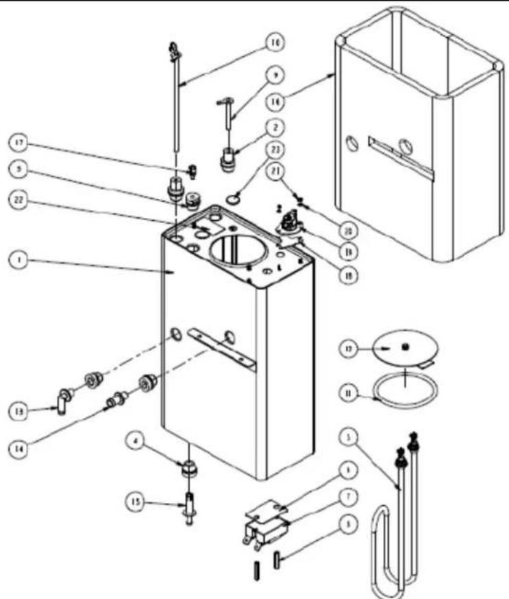
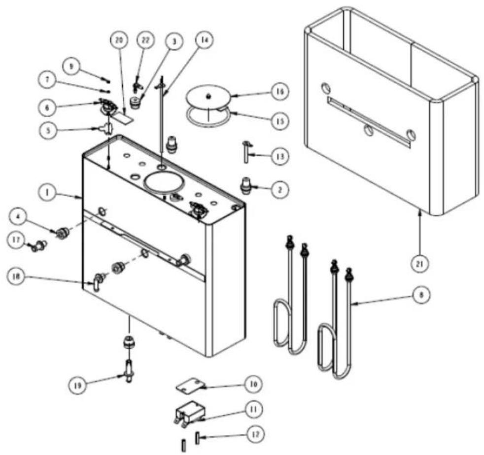
TANK ASSY, CBS-2131XTS Drawing number 1104.00082.00
| Qty | ||||
| Ref# | E213151 & E213153& E213157 | E213172 &E213173 | Part number | Description |
| 1 1 1 | 1114.00102.00 | WELDMEN T TANK, CBS-2131, TWO HEATERS, GROMMET | ||
| 2 2 2 | 1024.00053.00 | LEVEL AND TEMP PROBE GROMMET | ||
| 3 1 1 | 1024.00062.00 | GROMMET, SHORT, SILICONE, LEVEL AND TEMP PROBE | ||
| 4 3 3 | 1024.00050.00 | GROMMET, SILICONE, 11.4mm ID | ||
| 5 | 1 | 2 | 1107.00018.00 | HEATER ASSEMBLY, IMMERSION 3.0kW/240VAC |
| 5 | 1 | 2 | 1107.00019.00 | HEATER ASSEMBLY, IMMERSION 2.3kW/120VAC |
| 5 | — | 2 | 1107.00022.00 | HEATER ASSEMBLY, IMMERSION 1.7kW/120VAC |
| 5 | 1 | — | 1107.00021.00 | HEATER ASSEMBLY, IMMERSION 1.5kW/120VAC |
| 6 | 1 | 2 | 1003.00140.00 | ALUMINUM BRACKET FOR SSR |
| 7 | 1 | 2 | 1052.00033.00 | RELAY, SOLID STATE, 50A/480VAC, W/BUILD IN VARISTOR |
| 8 | 2 | 2 | 1081.00042.00 | STANDOFF, 1/4" HEX |
| 9 1 1 | 1112.00002.00 | PROBE WELDMENT, WATER LEVEL 2.25" LG | ||
| 10 1 1 | 1102.00161.00 | PROBE ASSEMBLY, TEMP. AND LLC, HWD-2100 | ||
| 11 1 1 | 1024.00007.00 | O-RING, DASH #344, TANK COVER | ||
| 12 1 1 | 1102.00007.00 | TANK COVER ASSEMBLY | ||
| 13 1 1 | 1023.00183.00 | FITTING, DILUTION, TBS-2121 | ||
| 14 1 1 | 1023.00167.00 | FITTING, BREW, GROMMET DESIGN | ||
| 15 1 1 | 1023.00166.00 | FITTING, COLD WATER INLET, GROMMET DESIGN | ||
| 16 1 1 | 1022.00063.00 | TANK INSULATION, CBS-2131e, GROMMET DESIGN | ||
| 17 1 1 | 1029.00023.00 | FITTING, SINGLE BARBED ELBOW, 1/4", KYNAR | ||
| 18 | 1 | 2 | 1003.00005.00 | BRACKET, ONE SHOT THERMOSTAT |
| 19 | 1 | 2 | 1053.00003.00 | THERMOSTAT, SINGLE SHOT, 240V/40A |
| 20 2 2 | 1083.00009.00 | WASHER, #6 SCREW, INTL TOOTH LOCKWASHER | ||
| 21 2 2 | 1084.00010.00 | NUT, HEX, #6-32, UNDERS ZED, ZINC PLATED | ||
| 22 1 1 | 1044.00004.00 | LABEL, DANGER-HIGH VOLTAGE | ||
| 23 | 2 | — | 1024.00054.00 | GROMMET, SILICONE PLUG |
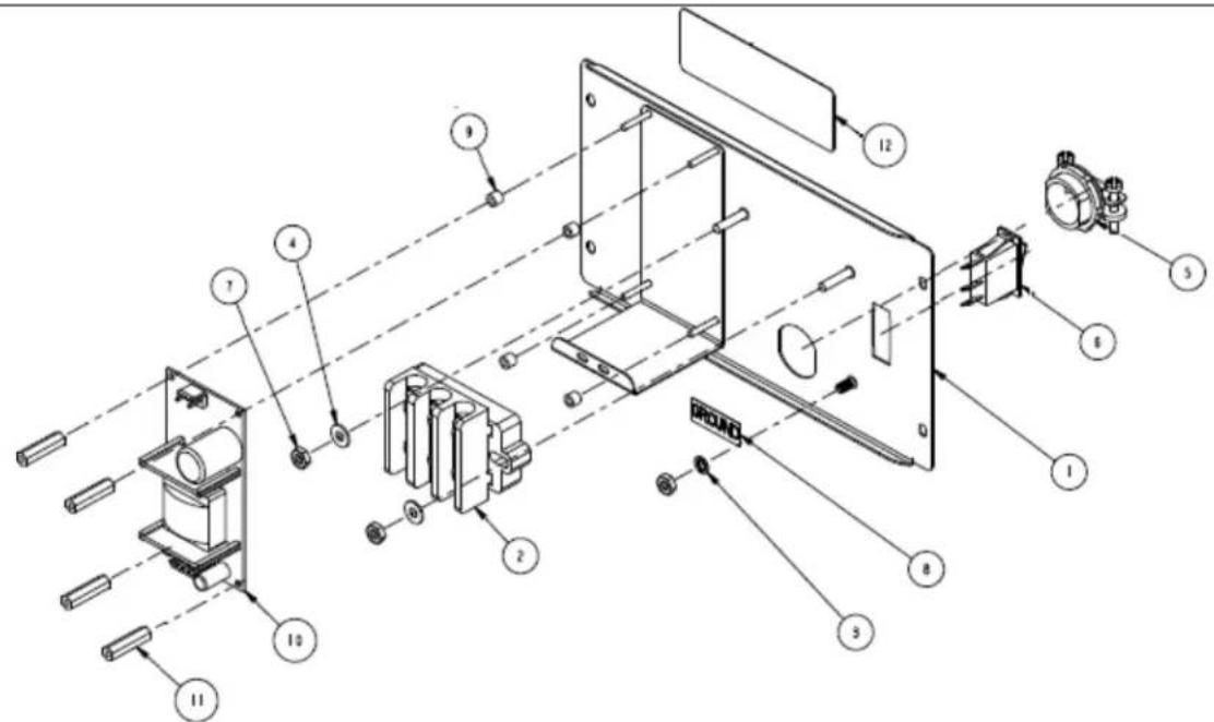
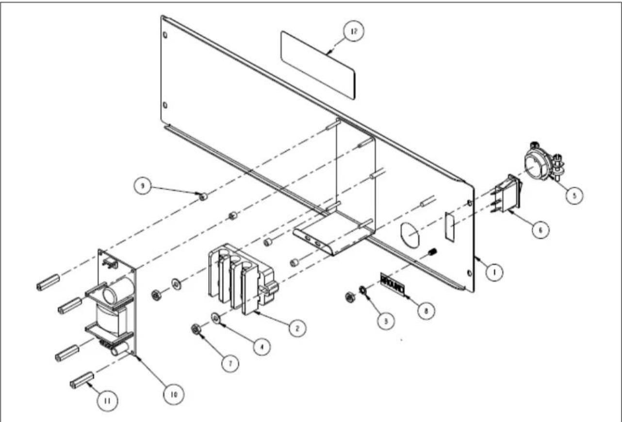
BACK PANEL ASSEMBLY, CBS-2131 1102.00209.00
| Ref# | Qty | Part number | Description |
| 1 | 1 111 | 2.00226.00 | WEL DMENT BACK COVER 2131 AND 2141 |
| 2 | 1 105 | 2.00002.00 | TERMINAL BLOCK, 3 POLE, W/ MARKING STRIP |
| 3 | 1 108 | 3.00011.00 | WASHER, #8 SCREW SIZE, INTERNAL TOOTH LOCK |
| 4 | 2 108 | 3.00016.00 | WASHER, #8 SCREW SIZE, FLAT |
| 5 | 1 108 | 6.00008.00 | CONNECTOR, CABLE CLAMP, 3/4" |
| 6 | 1 105 | 8.00020.00 | SWITCH, PWR ROCKER RED, ILLUM. 250VAC |
| 7 | 3 108 | 4.00006.00 | NUT, 8-32 18-8 HEX MACHINE SCREW |
| 8 | 1 104 | 4.00003.00 | LABEL GROUND |
| 9 | 4 108 | 1.00006.00 | SPACER, 6MM OD x 3.2MM ID x 5MM LG, Z/P |
| 10 | 1 105 | 2.00001.00 | POWER SUPPLY, 90-264VAC/24VDC, 1.8A |
| 11 | 4 102 | 9.00012.00 | SPACER, .25" HEX X 1" LG, FEM #4-40 THREAD |
| 12 | 1 104 | 6.00030.00 | LABEL WARNING, DISCONNECT FROM POWER SOURCE |
CBS-2132 XTS Drawing number 1104.00050.00
| CBS-2132 XTS Drawing number 1104.00050.00 | |||
| Ref# | Qty | Part number | Description |
| 1 | 1 1111.00062.00 WELDMENT | BODY, COMPLETE, CBS-2132 XTS, BB LOCK | |
| 2 | 2 1024.00049.00 EDGE PROTECTOR, 7.00"LG, CBS-2130 | ||
| 3 | 2 1086.00004.00 BUSHING, SNAP, 1" MOUNTING HOLE | ||
| 4 | 2 1024.00063.00 O-RING, 3 15/16" x 3/32" CS, DASH # 154, BUNA-N, DURO-A50 | ||
| 5 | 2 1102.00203.00 ASSEMBLY, SPRAY HOUSING, DSVP11 DESIGN | ||
| 6 | 8 1083.00010.00 WASHER, #10 SCREW W/NEOPRENE-BONDED SEAL | ||
| 7 | 13 1084.00006.00 NUT, 8-32 18-8 HEX MACHINE SCREW | ||
| 8 | 2 1102.00113.00 SWITCH, REED, ASSEMBLY | ||
| 9 | 4 1029.00006.00 #4-40 NYLON FINGER NUT | ||
| 10 | 1 1071.00010.00 FAUCET HPSC-BR-8 REGULAR HANDLE | ||
| 11 | 1 1031.00003.00 FITTING, BARB 3/8"ID x 1/4" FPT | ||
| 12 | 1 1057.00043.00 SOLENOID VALVE, SINGLE, 180 DEG, 240VDC | ||
| 13 | 2 1083.00005.00 WASHER, M4 18-8 INTERNAL TOOTH LOCKWASHER | ||
| 14 | 2 1082.00010.00 SCREW, M4x10 ZINC PLATED PAN PHILLIPS MACHINE | ||
| 15 | 1 1102.00243.00 ADAPTER ASSY, 3/4" BSP x 1/4" NPT x 3/8" TUBE | ||
| 16 | 1 1104.00052.00 TANK ASSY, 2 X 3.0kW/240V, CBS-2132 XTS | ||
| 16 | 1 1104.00057.00 TANK ASSY, 2 X 2.3 kW/240V, CBS-2132 XTS | ||
| 17 | 5 1083.00011.00 WASHER, #8 SCREW SIZE, INTERNAL TOOTH LOCK | ||
| 18 | 1 1025.00060.00 TUBE, 9/16"OD X 5/16"ID X 3.25"LG | ||
| 19 | 10 1086.00003.00 UNICLAMP, 15.9 HOSE OD CLAMP | ||
| 20 | 1 1029.00002.00 FITTING, HOSE BARB TEE, SIZE 3/8", NYLON | ||
| 21 | 1 1025.00058.00 TUBE, 9/16"OD X 5/16"ID X 25.00"LG | ||
| 22 | 1 1025.00077.00 TUBE, 9/16 OD x 5/16 ID x 6.50 LG. | ||
| 23 | 1 1025.00028.00 TUBE, 5/8"OD X 3/8"ID X 11"LG, HOT WATER VALVE, IN | ||
| 24 | 12 1084.00011.00 NUT, CLIP ON (J-NUT), #6-32, 22-20 GA., BLK-PH FINISH | ||
| 25 | 1 1102.00208.00 ASSEMBLY BACK PANEL, CBS-2132 AND 2142 | ||
| 26 | 13 1082.00017.00 SCREW, #6-32 X 1/2" TRUSS HD PHIL., MACHINE | ||
| 27 | 1 1023.00147.00 PLUG, TANK SERVICE DRAIN FOR 18GA AND UP BODY | ||
| 28 | 1 1024.00040.00 CARD PLUG, HWD-2100 | ||
| 29 | 1 1102.00210.00 ASSEMBLY FRONT PANEL, CBS-2130 | ||
| 30 | 6 1082.00058.00 SCREW, #8-32 X 5/8, FLAT HD, PH, 18-8 SS | ||
| 31 | 2 1102.00259.00 LOCATOR ASSEMBLY,L3S-10, GRAY, CBS-2130 | ||
| 32 | 2 1023.00221.00 ADAPTER FOR AIRPOT, GRAY, CBS-2130 | ||
| 33 | 2 1023.00159.00 CORNER INSERT | ||
| 34 | 1 1001.00127.00 COVER, TOP CBS-2132 AND 2142 | ||
| 35 | 2 1003.00259.00 BRACKET, BREW BASKET LOCK COVER | ||
| 36 | 5 1083.00009.00 WASHER, #6 SCREW, INTL TOOTH LOCKWASHER | ||
| 37 | 5 1084.00010.00 NUT, HEX, #6-32, UNDERSIZED, ZINC PLATED | ||
| 38 | 1 1001.00128.00 COVER, UPPER BASE, CBS-2132 AND 2142 | ||
| 39 | 1 1402.00037.00 HARNESS, HIGH AMP, CBS-2132 UL | ||
| 40 | 1 1402.00038.00 HARNESS, LOW AMP, CBS-2132 GRAVITY | ||
| 41 | 2 1025.00078.00 TUBE, 5/16 OD x 3/16 ID x 14.00 LG. | ||
| 42 | 1 1046.00006.00 LABEL, WARNING, "HOT WATER FAUCET" | ||
| 43 | 2 1046.00003.00 LABEL, CSD WARNING, 1.5" X 5.0" | ||
| 44 | 2 1024.00065.00 CONNECTOR, SILICONE, TANK TO BREW VALVE | ||
| 45 | 2 1086.00002.00 CLAMP, HOSE, SIZE "G" NYLON | ||
| 46 | 1 1041.00002.00 LABEL, "CSD" | ||
| 47 | 1 1041.00013.00 LABEL, XTS, 2130,2140 AND 2150 SERIES | ||
| 48 | 1 1065.00002.00 CONNECTOR, COPPER LUG | ||
| * | 2 B014218BN2 Plastic Brew Basket: Standard-included with all equipment | ||
| † | 2 B003218B1 OPTIONAL Stainless Steel Brew Basket | ||
| * | 4 1073.00019 One Inch legs [for 3 liter brewer configuration] | ||
| * | 4 1073.00016 201/2 Inch Legs [for 1 gallon brewer configuration] | ||
| *Standard-included with all equipment †-Option accessory for purchase | |||
CBS-2132 XTS Hot Water Tank Drawing 1104.00052.00
| Ref# | Qty | Part number | Description |
| 1 | 1 | 1114.00081.00 | WELDMENT TANK CBS-2132, GROMMET DESIGN |
| 2 | 2 1024.00053.00 LEVEL | AND TEMP PROBE GROMMET | |
| 3 | 2 | 1024.00062.00 | GROMMET, SHORT, SILICONE, LEVEL AND TEMP PROBE |
| 4 | 4 1024.00050.00 GROMMET, SILICONE, 11.4mm ID | ||
| 5 | 2 1003.00005.00 BRACKET, ONE SHOT THERMOSTAT | ||
| 6 | 2 1053.00003.00 THERMOSTAT, SINGLE SHOT, 240V/40A | ||
| 7 | 4 1083.00009.00 WASHER, #6 SCREW, INTL TOOTH LOCKWASHER | ||
| 8 | 2 | 1107.00020.00 | HEATER ASSEMBLY, IMMERSION 2300W/240VAC |
| 8 | 2 | 1107.00018.00 | HEATER ASSEMBLY, IMMERSION 3000W/240VAC |
| 9 | 4 1084.00010.00 NUT, HEX, #6-32, UNDERSIZED, ZINC PLATED | ||
| 10 | 2 1003.00140.00 ALUMINUM BRACKET FOR SSR | ||
| 11 | 2 | 1052.00033.00 RELAY, SOLID STATE, 50A/480VAC, W/BUILD IN VARISTOR | |
| 12 | 4 | 1081.00042.00 $TANDOFF, 1/4" HEX | |
| 13 | 1 1112.00002.00 PROBE | WELDMENT, WATER LEVEL 2.25" LG | |
| 14 | 1 1102.00161.00 PROBE | ASSEMBLY, TEMP. AND LLC, HWD-2100 | |
| 15 | 1 1024.00007.00 O-RING | DASH #344, TANK COVER | |
| 16 | 1 | 1102.00007.00 TANK COVER ASSEMBLY | |
| 17 | 2 1023.00167.00 FITTING | BREW, GROMMET DESIGN | |
| 18 | 1 | 1023.00183.00 FITTING, DILUTION, TBS-2121 | |
| 19 | 1 | 1023.00166.00 FITTING, COLD WATER INLET, GROMMET DESIGN | |
| 20 | 1 | 1044.00004.00 LABEL, WARNING-HIGH VOLTAGE | |
| 21 | 1 1022.00064.00 INSULATION TANK, ONE PIECE, CBS-2132 | ||
| 22 | 2 1029.00023.00 FITTING | SINGLE BARBED ELBOW, 1/4", KYNAR |
| BACK PANEL ASSEMBLY, CBS-2132 1102.00208.00 | ||||
| Ref# | Qty | Part number | Description | |
| 1 | 1 1112.00227.00 | WELDMENT, BACK COVER CBS-2132 AND 2142 | ||
| 2 | 1 1052.00002.00 | TERMINAL BLOCK, 3 POLE, W/ MARKING STRIP | ||
| 3 | 1 1083.00011.00 | WASHER, #8 SCREW SIZE, INTERNAL TOOTH LOCK | ||
| 4 | 2 1083.00016.00 | WASHER, #8 SCREW SIZE, FLAT | ||
| 5 | 1 1086.00008.00 | CONNECTOR, CABLE CLAMP, 3/4" | ||
| 6 | 1 1058.00020.00 | SWITCH, PWR ROCKER RED, ILLUM. 250VAC | ||
| 7 | 3 1084.00006.00 | NUT, 8-32 18-8 HEX MACHINE SCREW | ||
| 8 | 1 | 1044.00003.00 | LABEL GROUND | |
| 9 | 4 1081.00006.00 | SPACER, 6MM OD x 3.2MM ID x 5MM LG, Z/P | ||
| 10 | 1 | 1052.00001.00 | POWER SUPPLY, 90-264VAC/24VDC, 1.8A | |
| 11 | 4 1029.00012.00 | SPACER, .25" HEX X 1" LG, FEM #4-40 THREAD | ||
| 12 | 1 1046.00030.00 | LABEL WARNING, DISCONNECT FROM POWER SOURCE | ||
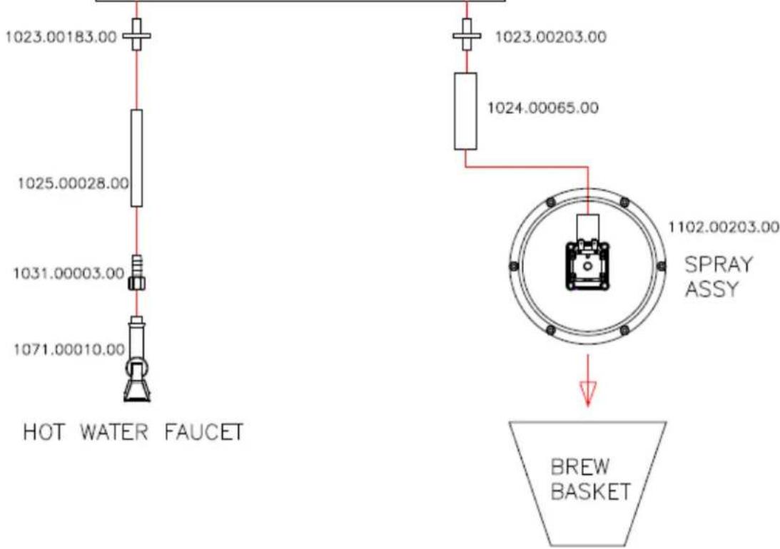
CBS 2131XTS
WATER HANDELING LAYOUT
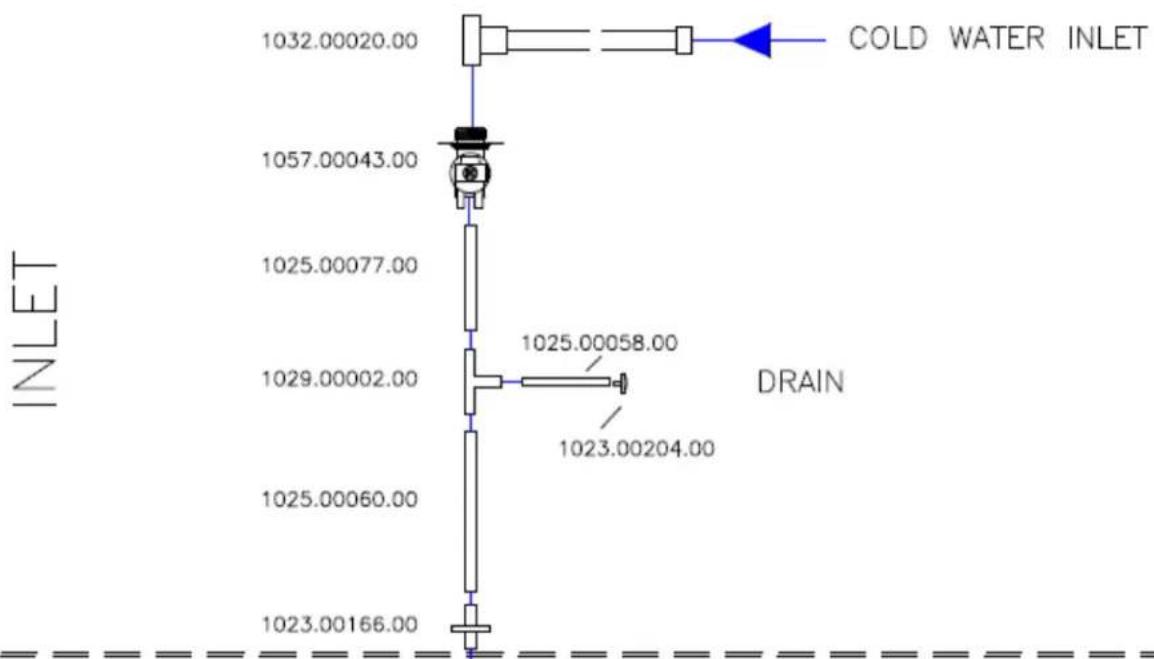
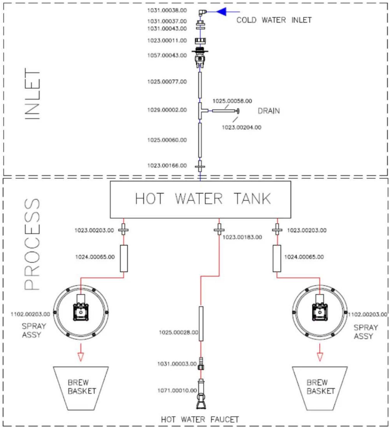
HOT WATER TANK
PROCESS
CBS 2132XTS
WATER HANDELING LAYOUT
flowchart
graph TD
    A["INLET"] --> B["COLD WATER INLET"]
    B --> C["DRAIN"]
    C --> D["1023.00204.00"]
    B --> E["1025.00058.00"]
    B --> F["1023.00203.00"]
    B --> G["1023.00183.00"]
    B --> H["1024.00065.00"]
    B --> I["1023.00203.00"]
    J["SPRAY ASSY"] --> K["BREW BASKET"]
    L["SPRAY ASSY"] --> M["BREW BASKET"]
    N["HOT WATER TANK"] --> O["1102.00203.00"]
    N --> P["1102.00203.00"]
    N --> Q["1102.00203.00"]
    N --> R["1102.00203.00"]
    N --> S["1102.00203.00"]
    N --> T["1102.00203.00"]
    N --> U["1102.00203.00"]
    N --> V["1102.00203.00"]
    N --> W["1102.00203.00"]
    N --> X["1102.00203.00"]
    N --> Y["1102.00203.00"]
    N --> Z["1102.00203.00"]
    N --> AA["1102.00203.00"]
    N --> AB["1102.00203.00"]
    N --> AC["1102.00203.00"]
    N --> AD["1102.00203.00"]
    N --> AE["1102.00203.00"]
    N --> AF["1102.00203.00"]
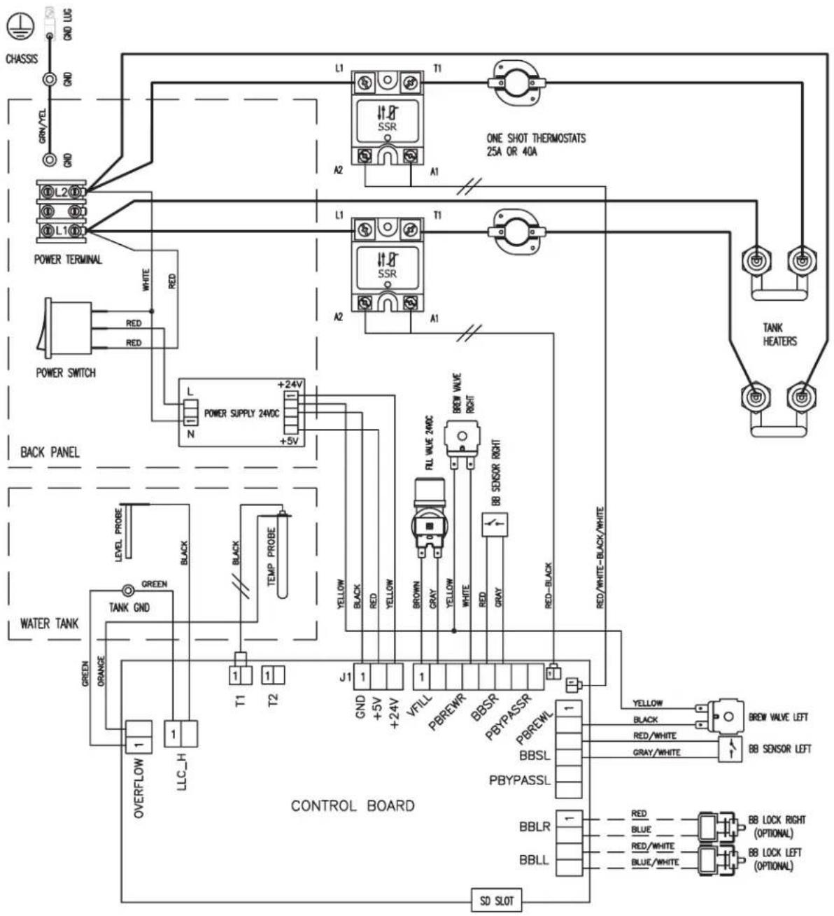
SKU NUMBER Heater Configuration
E213251 2 X 2.3 kW / 240 Vac
E213252 2 X 3.0 kW / 240 Vac
flowchart
graph TD
    A["CHASSIS"] --> B["GRN/YEL"]
    B --> C["GRND"]
    C --> D["L1"]
    D --> E["SSR"]
    E --> F["A1"]
    F --> G["TANK HEATERS"]
    G --> H["ONE SHOT THERMOSTATS 25A OR 40A"]
    I["POWER TERMINAL"] --> J["WHITE RED"]
    K["POWER SWITCH"] --> L["RED RED"]
    M["BACK PANEL"] --> N["L N POWER SUPPLY 24VDC +24V +5V"]
    O["WATER TANK"] --> P["GREEN GREEN ORANGE"]
    P --> Q["OVERFLOW LLC_H"]
    Q --> R["T1 T2"]
    S["TANK GND"] --> T["BLACK BLACK TEMP PROBE"]
    U["GND +5V +24V V/FILL PBREWR BBSR PBYPASSR PBREWL BBSL PBYPASSL"]
    V["J1 GND +5V +24V V/FILL PBREWR BBSR PBYPASSR PBREWL"]
    W["Yellow BLACK RED YELLOW BROWN GRAY YELLOW WHITE RED GRAY RED-Black RED/WHITE-BLK/WHITE"]
    X["BRL VALVE 24VDC"] --> Y["BB SENSOR RIGHT BB"]
    Z["BBLR"] --> AA["BBLL"]
    AB["SD SLOT"] --> AC["BB LOCK RIGHT (OPTIONAL) BB LOCK LEFT (OPTIONAL)"]
    AD["ONE SHOT THERMOSTATS 25A OR 40A"] --> AE["A2"]
    AE --> AF["L1"]
    AF --> AG["T1"]
    AG --> AH["TANK HEATERS"]
Go to fetco.com for the latest version of all information
Part B page 18 P123 partB REV 002 Technical Supplement March, 2016
| DWG. NAME: WIRING, CBS_2132XTS, (L1, L2 + GND), 2 HEATERS | |||
| DRAWN BY AG | SCALE N/A | MATERIAL N/A | |
| CHK'D SZ | SIZE A | DRAWING NO. 1401.00050.00 | |
| APP'D LW | DATE 04-22-2013 | ||
Go to fetco.com for the latest version of all information
Part B page 19 P123 partB REV 002 Technical Supplement March, 2016
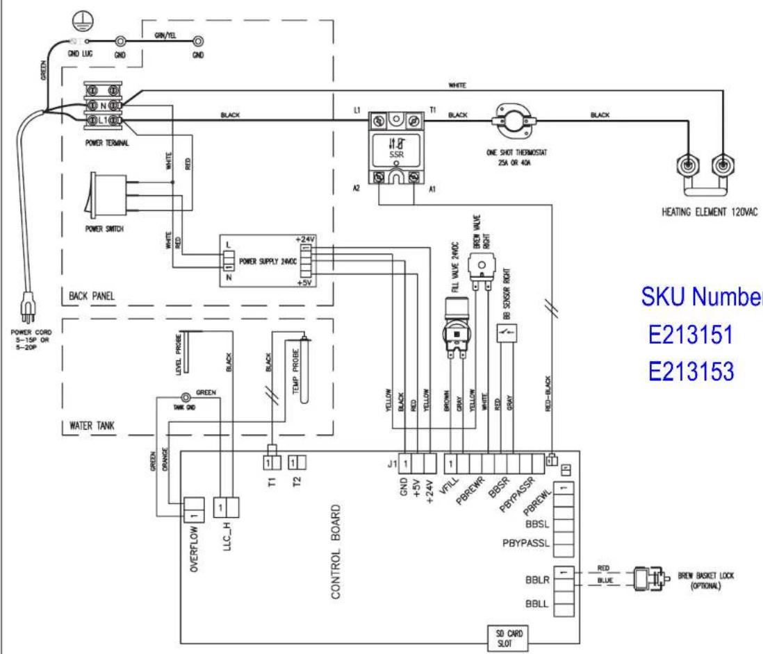
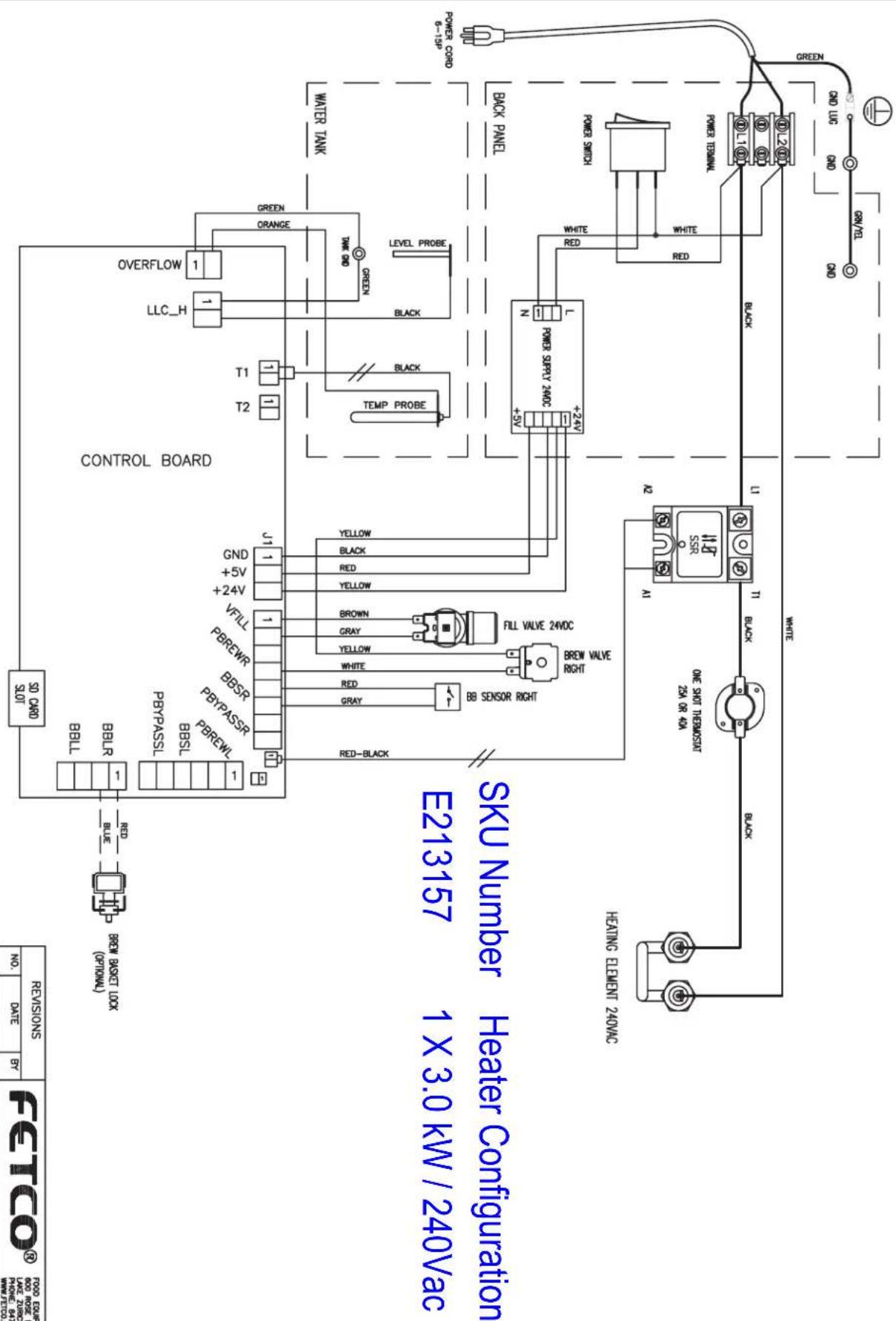
SKU Number Heater Configuration
E213151 1 X 2.3 kW / 120Vac
E213153 1 X 1.5 kW / 120Vac
| DWG. NAME: WIRING, CBS_2131XTS, (L1, N + GND), 1 HEATER | |||
| DRAWN BY AG | SCALE N/A | MATERIAL N/A | |
| CHK'D SZ | SIZE A | DRAWING NO. 1401.00051.00 | |
| APP'D LW | DATE 04-23-2013 | ||
PROPRIETARY AND CONFIDENTIAL
THE INFORMATION CONTAINED IN THIS DRAWING IS THE SOLE PROPERTY OF PETCO.
ANY REPRODUCTION IN PART OR AS A WHOLE WITHOUT THE WRITTEN PERMISSION OF FEDO IS PROHIBITED.
| REVISIONS | FTCOSRUM FORUM TECHNOLOGY COMPANY500 MOSF. NO.LAKE ZINCKI, IL 60017WATERC2003.COM | ||||||
| No. | DATE | BY | |||||
| A | 07/30/2013 | AG | DWC, NAME: | ||||
| B | 09/12/2013 | AG | WRING, OBS-2131XTS, (LI, 12 + GND), 1 HEATER | ||||
| C | 12/11/2013 | AG | DRAWN BY AG | SCALE N/A | MATTHEAL N/A | ||
| D | 03/24/2014 | AG | CHK'D | SZ | SIZE A | DRAWING NO. | 1401.00053.00 |
| E | 02/27/2015 | SZ | APP'D | LW | DATE OF 07-30-2013 | ||
| SKU NUMBER | Heater Configuration | . |
| E213172 | 1 X 1.7 kW 120 Vac Cord and Plug from Factory | |
| OPTION BY USER | 2 X 1.7 kW 120/208-240Vac to terminal block-field installed | |
| E213173 | 1 X 2.3 kW 120 Vac Cord and Plug from Factory | |
| OPTION BY USER | 2 X 2.3 kW 120/208-240Vac to terminal block-field installed |
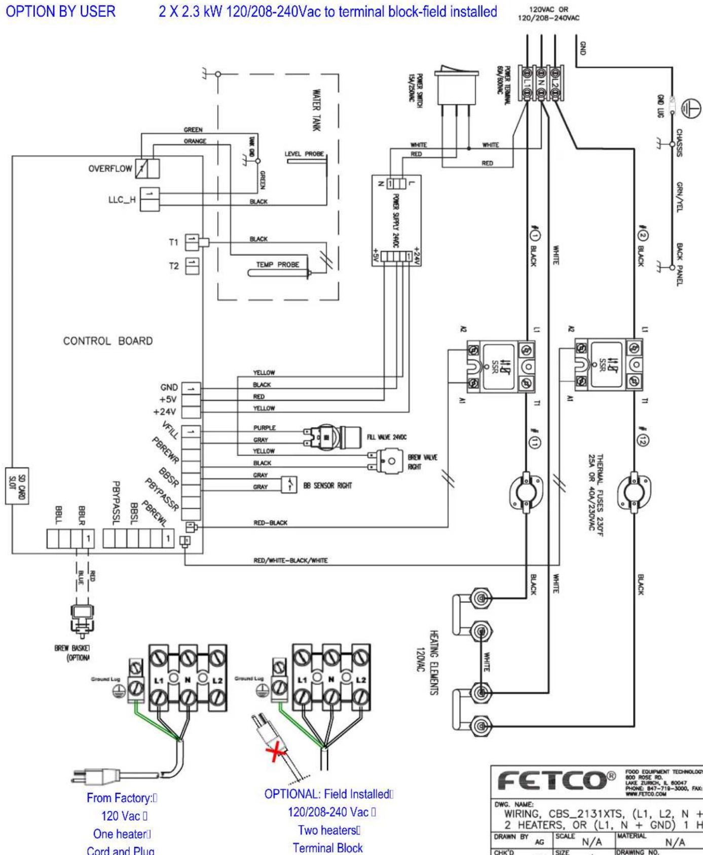
| DWG. NAME: WIRING, CBS_2131XTS, (L1, L2, N + GND) 2 HEATERS, OR (L1, N + GND) 1 HEATER | |||
| DRAWN BY AG | SCALE N/A | MATERIAL N/A | |
| CHK'D SZ | SIZE A | DRAWING NO. 1401.00091.00 | |
| APP'D LW | DATE 04-10-2014 | ||
INSTRUCTIONS TO SET BREWER
Change brewer for brew size: CBS-2131 3L; CBS-2131; 1G CBS-2132 3L; CBS-2132 1G
Brewer is factory set for three liter brew capacity. User can configure the brewer for 1 gallon brew To change brewer configuration: Access the General Service Menu
There are five service menus:
PROGRAM, GENERAL, INPUTS, OUTPUTS, and OTHER (select OTHER in service menu to change to 1 gallon).
→Enter Service Menu by accessing the power switch on back of the panel
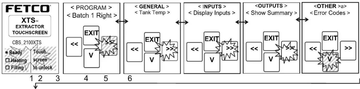
Service menu is accessed when "PROGRAM" screen (2) displays
1)-Switch power "OFF" with power switch located on rear of brewer
2)-After at least ten seconds: Turn power switch "ON"
3)-Quickly touch and hold the XTS screen to enter the programming screens as shown below (screen1)
4)-When entering The SERVICE MENU: the first screen in the group is "PROGRAM" (screen 2)
5)-Use right and left arrow icons to navigate through the five main SERVICE (2-6 below) menu groups.
6)-Proceed to "OTHER" screen (screen 6). Use down arrow icon, as illustrated, to access second level (6&7).
flowchart
graph LR
    A["FETCO XTS EXTRACTOR TOUCHSCREEN"] --> B["1"]
    A --> C["2"]
    A --> D["3"]
    B --> E["Program"]
    C --> E
    D --> E
    E --> F["< Program ><br>< Batch 1 Right >"]
    F --> G["EXIT"]
    G --> H["V"]
    H --> I["6"]
    I --> J["GENERAL"]
< Tank Temp >]
    J --> K["EXIT"]
    K --> L["V"]
    L --> M["6"]
    M --> N["INPUTS ><br>< Display Inputs >"]
    N --> O["EXIT"]
    O --> P["V"]
    P --> Q["6"]
    Q --> R["OUTPUTS ><br>< Show Summary >"]
    R --> S["EXIT"]
    S --> T["V"]
    T --> U["6"]
    U --> V["OTHER >a ><br>< Error Codes >"]
flowchart
graph LR
    A["FETCO"] --> B["Select Model"]
    B --> C["Select Factory"]
    C --> D["Res to Factory"]
    D --> E["Res to Default"]
    E --> F["Res to Factory"]
    F --> G["Res to Factory"]
    G --> H["Res to Factory"]
    H --> I["Res to Factory"]
    I --> J["Res to Factory"]
    J --> K["Res to Factory"]
    K --> L["Res to Factory"]
    L --> M["Res to Factory"]
    M --> N["Res to Factory"]
    N --> O["Res to Factory"]
    O --> P["Res to Factory"]
    P --> Q["Res to Factory"]
    Q --> R["Res to Factory"]
    R --> S["Res to Factory"]
    S --> T["Res to Factory"]
    T --> U["Res to Factory"]
    U --> V["Res to Factory"]
    V --> W["Res to Factory"]
    W --> X["Res to Factory"]
    X --> Y["Res to Factory"]
    Y --> Z["Res to Factory"]
    Z --> AA["Res to Factory"]
    AA --> AB["Res to Factory"]
    AB --> AC["Res to Factory"]
    AC --> AD["Res to Factory"]
    AD --> AE["Res to Factory"]
    AE --> AF["Res to Factory"]
    AF --> AG["Res to Factory"]
    AG --> AH["Res to Factory"]
    AH --> AI["Res to Factory"]
    AI --> AJ["Res to Factory"]
    AJ --> AK["Res to Factory"]
    AK --> AL["Res to Factory"]
    AL --> AM["Res to Factory"]
    AM --> AN["Res to Factory"]
    AN --> AO["Res to Factory"]
    AO --> AP["Res to Factory"]
    AP --> AQ["Res to Factory"]
    AQ --> AR["Res to Factory"]
    AR --> AS["Res to Factory"]
    AS --> AT["Res to Factory"]
    AT --> AU["Res to Factory"]
    AU --> AV["Res to Factory"]
    AV --> AW["Res to Factory"]
    AW --> AX["Res to Factory"]
    AX --> AY["Res to Factory"]
    AY --> AZ["Res to Factory"]
    AZ --> BA["Res to Factory"]
    BA --> BB["Res to Factory"]
    BB --> BC["Res to Factory"]
    BC --> BD["Res to Factory"]
    BD --> BE["Res to Factory"]
    BE --> BF["Res to Factory"]
    BF --> BG["Res to Factory"]
    BG --> BH["Res to Factory"]
    BH --> BI["Res to Factory"]
    BI --> BJ["Res to Factory"]
    BJ --> BK["Res to Factory"]
    BK --> BL["Res to Factory"]
    BL --> BM["Res to Factory"]
    BM --> BN["Res to Factory"]
    BN --> BO["Res to Factory"]
    BO --> BP["Res to Factory"]
    BP --> BQ["Res to Factory"]
    BQ --> BR["Res to Factory"]
    BR --> BS["Res to Factory"]
    BS --> BT["Res to Factory"]
    BT --> BU["Res to Factory"]
    BU --> BV["Res to Factory"]
    BV --> BW["Res to Factory"]
    BW --> BX["Res to Factory"]
    BX --> BY["Res to Factory"]
    BY --> BZ["RES TO FACTOR TOUCHSCREEN"]
    BZ --> CA["XTS™ EXTRACTOR TOUCHSCREEN"]
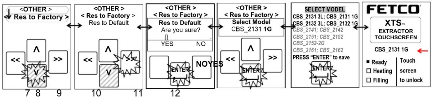
Use right and left arrow icons to navigate between the five main SERVICE menus. First menu screen Is “PROGRAM” Highlight programming path and use arrows to locate “Select Model” programming screen
7)-Use right and left arrow icons to navigate to Restore to Factory defaults (Res to Factory) (screen 7).
8)-Use down arrow to set brewer to access factory default settings for the brewer configuration desired (screen 8)
9)-Enter "YES" to restore factory defaults. This will configure the brewer to the correct brew capacity (screen 9)
10) Right and left arrow icons to navigate CBS_2131 3Liter; CBS_2131 1Gallon CBS_2132 3Liter; CBS_2132 1Gallon
Highlight desired brewer type and use the arrow icons to navigate service menu screens.
HIGHLIGHT
11)-Press "ENTER" and navigate sing UP arrows to home screen to brew (screens 10&11)
!PLEASE NOTE! ONLY SELECT: CBS_2131 3Liter; CBS_2131 1Gallon CBS_2132 3Liter; CBS_2132 1Gallon . Do not select any other configuration. Verify the configuration on the home screen (screen 12-marked by arrow)
12)-Home screen
User must setup the brewer before installing. First install legs and adjust for 1 gallon
1) Select leg height and attach for either 3 Liter / 1 Gallon dispensing
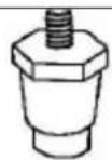
1" legs -
Attach this length for
3 Liter airport configuration (Default).
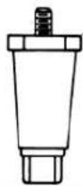
2-1/2" legs -
Attach this length for 1 Gallon dispenser use.
NOTE: See reverse side to "select brewer configuration to set brewer for 3 Liter or 1 Gallon configuration
2) Adjust dispenser locator for either 3 Liter / 1 Gallon dispensing
natural_image
Technical line drawing of a mechanical device with no visible text or symbols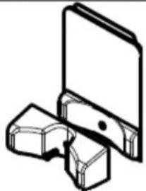
natural_image
Simple line drawing of a laptop with an open screen and a folded paper (no text or symbols)Set Dispenser Locator ← shown with 3 liter airport Locator -(Factory installed
Shown with 1 gallon dispenser locator→ -(User option)
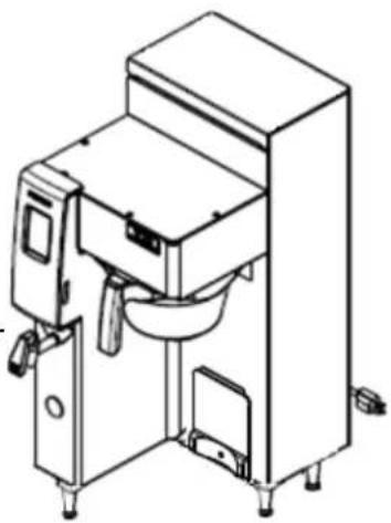
natural_image
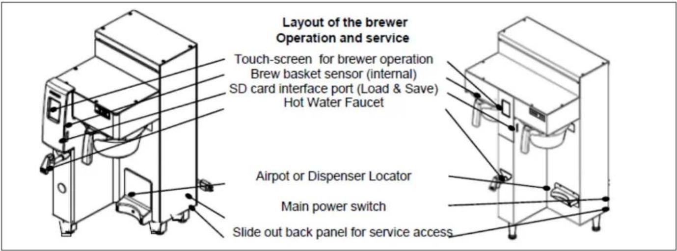
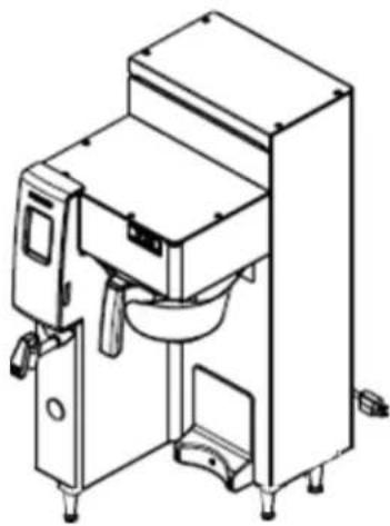
Technical line drawing of a mechanical device with no visible text or symbolsLayout of the brewer
Operation and service
Touch-screen for brewer operation
Brew basket
SD card interface port (Load & Save)
Hot Water Faucet
Airport or Dispenser Locator (Two for dual side)
Main power switch Slide out back panel for service access
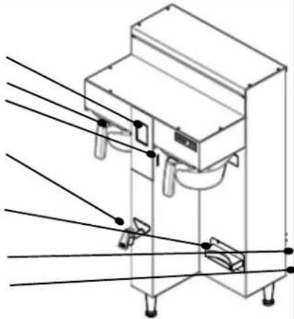
natural_image
Technical line drawing of a mechanical device with mounting feet and wiring (no text or symbols)Layout for installing brewer
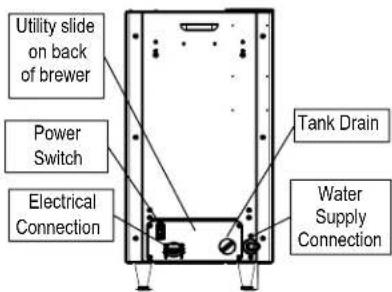
END OF SECTION NOTES
- Extractor Touch Screen Commercial Hot Beverage Equipment
- Instructions for brew operation-fast brew
- Setup is simple
- Brew operation is simple. The intuitive touch screen-STARTS THE BREW
- Service & Programming
- To access the General Service Menu
- Programming menu layout
- Batch 1 Right
- BREW AT TEMPERATURE DEFINITONS
- BREW AT TEMP: "ON"
- (DEFAULT: FACTORY PROGRAMMED INTO BREWER)
- BREW AT TEMP: AUTO
- USER SELECTABLE
- FETCO
- BREW AT TEMP: OFF
- (Not recommended)
- ECO MODE-Energy saving mode DEFINITONS
- To return from ECO-Mode
- ECO
- How to calibrate the flow rate
- 1) MEASURE THE FLOW RATE:
- 2) AUTOMATIC Built-in CALIBRATE THE FLOW RATE
- 3) MANUAL METHOD Operator input: CALIBRATE THE FLOW RATE
- Operator Training
- Pay particular attention to the following areas:
- After Each Brew:
- Every Day:
- Weekly
- Warning
- Safety Notes
- FETCO Touch Screen Models: CBS-2130XTS
- Service Guide to a Successful Installation
- General:
- Electrical:
- Plumbing:
- Tank Drain
- Specifications and Requirements
- Water Requirements:
- Coffee Filter Size:
- Temperature, as set by factory:
- Installation safety and hygiene directions-For International and CE equipment
- CBS 2131XTS
- WATER HANDELING LAYOUT
- CBS 2132XTS
- INSTRUCTIONS TO SET BREWER
- Change brewer for brew size: CBS-2131 3L; CBS-2131; 1G CBS-2132 3L; CBS-2132 1G
- User must setup the brewer before installing. First install legs and adjust for 1 gallon
- 1) Select leg height and attach for either 3 Liter / 1 Gallon dispensing
- 2) Adjust dispenser locator for either 3 Liter / 1 Gallon dispensing
- Layout of the brewer
- Operation and service
- Layout for installing brewer
Brand : Fetco
Model : CBS-2131XTS
Category : Coffee maker