
PTC-285T - Security Camera DataVideo - Free user manual and instructions
Find the device manual for free PTC-285T DataVideo in PDF.


| Product Type | 4K HDBaseT Tracking PTZ Camera |
| Image Sensor | 1/2.8" CMOS, 8.51 megapixels |
| Optical Zoom | 12x |
| Digital Zoom | 16x |
| Video Output Interfaces | HDMI 2.0, 3G-SDI, HDBaseT/PoE (RJ-45) |
| Video Format | 2160p60/59.94/50/30/29.97/25, 1080p60/59.94/50/30/29.97/25, 1080i60/59.94/50, 720p60/59.94/50 |
| Pan Range | 300° |
| Tilt Range | +130° to -15° |
| Preset Positions | 255 |
| Control Protocols | VISCA, Pelco-D, Pelco-P, DVIP, VISCA over IP |
| Remote Control | IR remote controller, Web UI, RS-422 |
| Audio Input | 3.5mm (mic/line in, switchable via Web UI) |
| Dimensions (W x H x D) | 173 x 219 x 189.08 mm |
| Weight | 2.6 kg |
| Power Supply | DC 12V, 22W (PoE IEEE 802.3at supported) |
| Operating Temperature | 0°C to 40°C |
| AI Auto Tracking | Single-person and multi-person tracking modes |
| Firmware Update | Via Web UI or USB flash drive |
| Mounting | Tripod screw hole (1/4-20 UNC) and ceiling bracket |
| Maintenance | Use soft cloth with neutral detergent; avoid liquid cleaners near unit |
| Safety | Do not expose to water or place near heat sources; unplug before cleaning |
| Optional Accessories | WM-1, WM-10, WM-11 (ceiling mounts) |
Frequently Asked Questions - PTC-285T DataVideo
User questions about PTC-285T DataVideo
0 question about this device. Answer the ones you know or ask your own.
Ask a new question about this device
Download the instructions for your Security Camera in PDF format for free! Find your manual PTC-285T - DataVideo and take your electronic device back in hand. On this page are published all the documents necessary for the use of your device. PTC-285T by DataVideo.
USER MANUAL PTC-285T DataVideo
natural_image
Technical line drawing of a device with a central circular component and labeled 'datavideo' at the base (no other text or symbols)4K HDBaseT Tracking PTZ Camera
PTC-285T
Instruction Manual
Table of Contents
TABLE OF CONTENTS 2
FCC COMPLIANCE STATEMENT .... 5
WARNINGS AND PRECAUTIONS 5
WARRANTY 7
STANDARD WARRANTY....7
THREE YEAR WARRANTY....7
DISPOSAL 8
1. PRODUCT OVERVIEW....9
FEATURES....9
2. LOCATION AND FUNCTION OF PARTS 10
3. BASIC SETUP 14
3.1 POWER-ON INITIALIZATION....14
3.2 VIDEO OUTPUT 14
HDBaseT/POE Port 14
HDMI Video OUT 16
3G-SDI Video Output....16
4. REMOTE CONTROL AND ON-SCREEN MENU.... 17
4.1 REMOTE CONTROL FUNCTIONS....17
4.2 OSD MENU 21
4.3 PROFESSIONAL JARGON EXPLANATIONS OF THE OSD MENU 32
5. INSTRUCTION FOR INSTALLATION.... 33
6. NETWORK CONNECTION 39
6.1 DHCP MODE 40
6.2 STATIC IP....42
6.3 DVIP 43
7. HOW TO USE PTC-285T'S AI AUTO TRACKING 46
7.1 HOW TO TURN ON THE AI AUTO-TRACKING FUNCTION ....46
7.2 HOW TO TURN OFF THE AI AUTO-TRACKING FUNCTION ....47
7.3 SINGLE-PERSON SCENE AUTO-TRACKING MODE 48
7.4 MULTI-PERSON SCENE AUTO-TRACKING MODE....49
- WEB USER INTERFACE....52
8.1 LIVE 52
8.2 VIDEO....53
8.2.1 How to Connect the PTC-285T to a Datavideo Switcher after a 60FPS/50FPS Video Streaming (Take the HS-1300 as an example)....57
8.3 IMAGE....61
8.4 AUDIO....62
8.5 SYSTEM....64
8.6 NETWORK....66
8.7 INFORMATION....76
8.8 THE PTZ CONTROL AREA OF THE WEB UI....78
-
HOW TO USE THE WEB UI TO SET AND CALL PRESETS 81
-
CONTROL THE CAMERA BY THE PTZ VIEW ASSIST APP 82
-
DIP SWITCH SETTINGS 83
11.1 DIP SWITCH SW1 83
11.2 DIP SWITCH SW2 (IRID) 84
-
HOW TO PLAY THE RTSP STREAM BY THE VLC PLAYER.... 85
-
HOW TO PLAY THE MULTICAST BY THE VCL PLAYER 87
-
HOW TO STREAM TO FACEBOOK 88
-
HOW TO STREAM TO YOUTUBE 99
-
HOW TO DO THE SRT STREAMING BY THE VMIX SOFTWARE.... 103
-
REMOTE CONTROL PORT PINOUTS 116
-
FIRMWARE UPDATE.... 118
18.1 FIRMWARE UPDATE BY THE PTC-285T FIRMWARE UPDATE TOOL....118
18.2 FIRMWARE UPDATE BY THE USB FLASH DRIVE 122
-
FREQUENTLY-ASKED QUESTIONS.... 125
-
DIMENSIONS.... 127
-
SPECIFICATIONS.... 128
SERVICE AND SUPPORT 132
Disclaimer of Product and Services
The information offered in this instruction manual is intended as a guide only. At all times, Datavideo Technologies will try to give correct, complete and suitable information. However, Datavideo Technologies cannot exclude that some information in this manual, from time to time, may not be correct or may be incomplete. This manual may contain typing errors, omissions or incorrect information. Datavideo Technologies always recommend that you double check the information in this document for accuracy before making any purchase decision or using the product. Datavideo Technologies is not responsible for any omissions or errors, or for any subsequent loss or damage caused by using the information contained within this manual. Further advice on the content of this manual or on the product can be obtained by contacting your local Datavideo Office or dealer.
FCC Compliance Statement
This device complies with part 15 of the FCC rules. Operation is subject to the following two conditions:
(1) This device may not cause harmful interference, and
(2) This device must accept any interference received, including interference that may cause undesired operation.
Warnings and Precautions
- Read all of these warnings and save them for later reference.
- Follow all warnings and instructions marked on this unit.
- Unplug this unit from the wall outlet before cleaning. Do not use liquid or aerosol cleaners. Use a damp cloth for cleaning.
- Do not use this unit in or near water.
- Do not place this unit on an unstable cart, stand, or table. The unit may fall, causing serious damage.
- Slots and openings on the cabinet top, back, and bottom are provided for ventilation. To ensure safe and reliable operation of this unit, and to protect it from overheating, do not block or cover these openings. Do not place this unit on a bed, sofa, rug, or similar surface, as the ventilation openings on the bottom of the cabinet will be blocked. This unit should never be placed near or over a heat register or radiator. This unit should not be placed in a built-in installation unless proper ventilation is provided.
- This product should only be operated from the type of power source indicated on the marking label of the AC adapter. If you are not sure of the type of power available, consult your Datavideo dealer or your local power company.
-
Do not allow anything to rest on the power cord. Do not locate this unit where the power cord will be walked on, rolled over, or otherwise stressed.
-
If an extension cord must be used with this unit, make sure that the total of the ampere ratings on the products plugged into the extension cord do not exceed the extension cord's rating.
-
Make sure that the total amperes of all the units that are plugged into a single wall outlet do not exceed 15 amperes.
-
Never push objects of any kind into this unit through the cabinet ventilation slots, as they may touch dangerous voltage points or short out parts that could result in risk of fire or electric shock. Never spill liquid of any kind onto or into this unit.
-
Except as specifically explained elsewhere in this manual, do not attempt to service this product yourself. Opening or removing covers that are marked “Do Not Remove” may expose you to dangerous voltage points or other risks, and will void your warranty. Refer all service issues to qualified service personnel.
-
Unplug this product from the wall outlet and refer to qualified service personnel under the following conditions:
a. When the power cord is damaged or frayed;
b. When liquid has spilled into the unit;
c. When the product has been exposed to rain or water;
d. When the product does not operate normally under normal operating conditions. Adjust only those controls that are covered by the operating instructions in this manual; improper adjustment of other controls may result in damage to the unit and may often require extensive work by a qualified technician to restore the unit to normal operation;
e. When the product has been dropped or the cabinet has been damaged;
f. When the product exhibits a distinct change in performance, indicating a need for service.
Warranty
Standard Warranty
- Datavideo equipment are guaranteed against any manufacturing defects for one year from the date of purchase.
- The original purchase invoice or other documentary evidence should be supplied at the time of any request for repair under warranty.
- The product warranty period begins on the purchase date. If the purchase date is unknown, the product warranty period begins on the thirtieth day after shipment from a Datavideo office.
- All non-Datavideo manufactured products (product without Datavideo logo) have only one year warranty from the date of purchase.
- Damage caused by accident, misuse, unauthorized repairs, sand, grit or water is not covered under warranty.
- Viruses and malware infections on the computer systems are not covered under warranty.
- Any errors that are caused by unauthorized third-party software installations, which are not required by our computer systems, are not covered under warranty.
- All mail or transportation costs including insurance are at the expense of the owner.
- All other claims of any nature are not covered.
- All accessories including headphones, cables, and batteries are not covered under warranty.
- Warranty only valid in the country or region of purchase.
- Your statutory rights are not affected.
Three Year Warranty
- All Datavideo products purchased after July 1st, 2017 are qualified for a free two years extension to the standard warranty, providing the product is registered with Datavideo within 30 days of purchase.

- Certain parts with limited lifetime expectancy such as LCD panels, DVD drives, Hard Drive, Solid State Drive, SD Card, USB Thumb Drive, Lighting, Camera module, PCIe Card are covered for 1 year.
- The three-year warranty must be registered on Datavideo's official website or with your local Datavideo office or one of its authorized distributors within 30 days of purchase.
Disposal

natural_image
Symbol of a trash bin crossed with diagonal lines, representing no waste or discharge (no text or labels)For EU Customers only - WEEE Marking
This symbol on the product or on its packaging indicates that this product must not be disposed of with your other household waste. Instead, it is your responsibility to dispose of your waste equipment by handing it over to a designated collection point for the recycling of waste electrical and electronic equipment. The separate collection and recycling of your waste equipment at the time of disposal will help to conserve natural resources and ensure that it is recycled in a manner that protects human health and the environment. For more information about where you can drop off your waste equipment for recycling, please contact your local city office, your household waste disposal service or the shop where you purchased the product.
1. Product Overview
The PTC-285T series features a large 1/2.8" CMOS sensor, supports high-quality 2160p50/60 UHD video output, features 12x optical zoom, 16x digital zooms and supports versatile outputs, including 3G-SDI, HDMI, IP stream, NDI (PTC-285T NDI, optional). The PTC-285T series will be the ideal choice for taking your remote camera production to the next level.
Features
• 2160p50/59.94/60 PTZ camera
• 12x Optical Zoom, 16x Digital Zoom
• 4K Video interfaces: HDMI, IP (H.264 & H.265)
• 2160p and 1080p (3G-SDI) Simultaneous video output
• RS-422 Serial Port Control
• External audio input: 3.5mm audio in/line in (switchable on the web UI)
- Friendly web UI
- White color model available.
2. Location and Function of Parts
Front of Camera
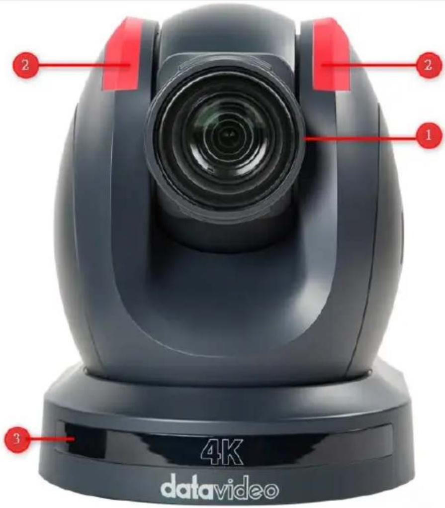
| 1 | LensBuilt-in 1/2.8” 8.51M Pixel CMOS 4K color camera with white balance control, backlight compensation, automatic gain and etc. |
| 2 | Tally LEDTally lamp will be turned ON upon receiving the ON signal. |
| 3 | Sensor for Remote ControlRemote control IR receiver |
| Rear of Camera | |
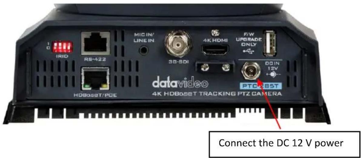
| 1 | USB Port This USB port is used for updating firmware. Users can save the latest version of firmware in a USB flash drive and then insert it into this interface for firmware updating. Note: After inserting the USB flash drive, please remember to turn "ON" the SETUP->USB UPGRADE from the OSD menu of the PTC-285T camera. |
| 2 | Power Input DC in socket connects the supplied 12V PSU. The connection can be secured by screwing the outer fastening ring of the DC In plug to the socket. |
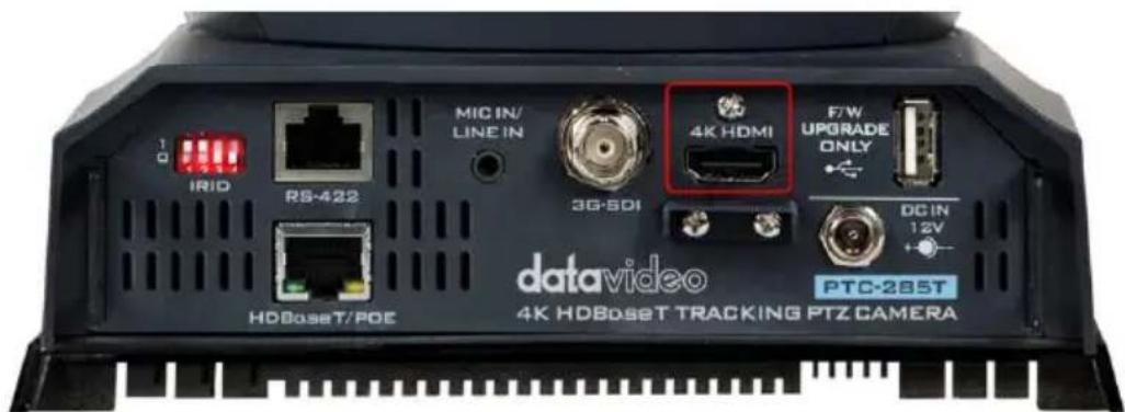
| 3 | 4K HDMI OUTThe 4K HDMI OUT allows you to connect an external HDMI monitor via an HDMI cable. |
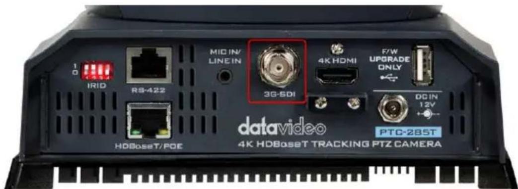
| 4 | 3G-SDI OUTThe 3G-SDI OUT allows you to connect an external monitor via an SDI cable. |
| 5 | MIC IN/LINE INThe 3.5mm audio input receives external audio. |
| 6 | RS-422 Interface (RJ-45)The RS-422 interface serves to connect external RS-422 devices. Use an Ethernet cable to connect external RS-422 controllers. See “Section 17 Remote Control Port Pinouts” for making the cable for the RS-422 interface. |
| 7 | IRID InterfaceThis interface allows users to use the DVIP Switch to control the numbering of the camera on the remote controller. Users can use this interface to set the camera to any number from No.1 to No. 4 in order to use remote controller to control the camera. |
| 8 | HDBaseT/POE InterfaceConnects the camera to the receiver box, thereby extending video transmission up to 100m. Use a CAT5e/6 Ethernet cable to connect this port to the HDBaseT port of the receiver box which in turn outputs the HDMI video to an externally connected monitor. Moreover, this interface can support the PoE (Power over Ethernet) technology. |
Bottom of Camera
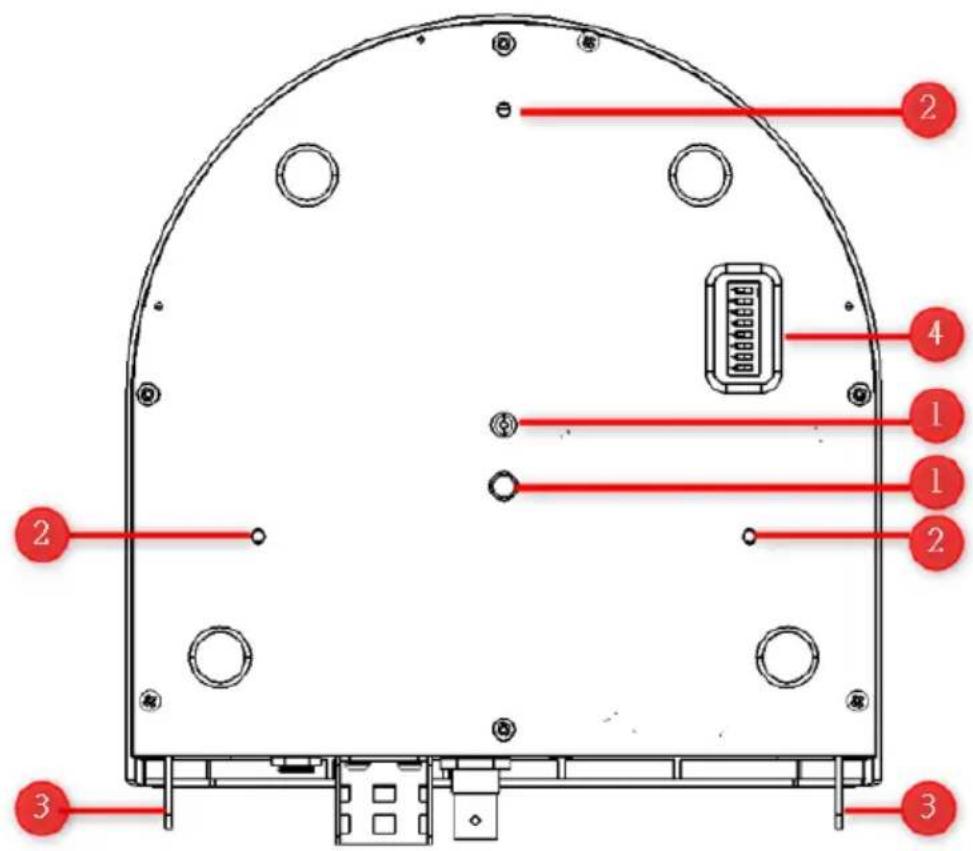
| 1 | Tripod Screw Hole allows the user to mount the camera on the tripod. |
| 2 | Screw HoleScrew holes for ceiling bracket mounting. |
| 3 | For Safety RopeTies safety rope for fixing the camera to the ceiling. |
| 4 | DIP SwitchThis DIP Switch allows users to adjust needed parameters such as VISCA ID, resolutions, remote control protocol and video modes. |
3. Basic Setup
3.1 Power-On Initialization
As shown in the diagram below, after you plug in the power cord, the tally light in the front will start flashing red and will be OFF as soon as the power-on initialization is complete. The camera head should be at the HOME position with the lens facing front. If the power is inserted, the camera lens will go back to the position where the camera power is off last time.
3.2 Video Output
You are allowed to view the camera video via HDBaseT/POE port, 4K HDMI OUT and 3G-SDI OUT.
HDBaseT/POE Port
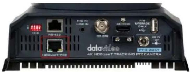
Please follow following steps for viewing the camera video from the web UI.
- Connect the PTC-285T camera directly to your PC/Notebook PC
- Connect the PTC-285T to your PC or laptop by an Ethernet Cable.
- Open the web UI by the connected PC or laptop and then please enter the default IP address into the address bar of the web browser.
Note: The default static IP address of the PTC-285T is 192.168.100.88.
-
The login page of the web UI will be opened, please enter the user name and password (the default user name and password are admin/admin).
-
Open the preview window for previewing the video which is shot by the camera.
- Connect the PTC-285T camera to your PC or laptop by a router.
- Please set the Ethernet IP address of your PC or laptop as 192.168.100.x(x means 0-255) and it will be at the same local area network as the PTC-285T.
- Please use an RJ-45 Ethernet cable to connect from the HDBaseT/POE port on the rear panel of the PTC-285T to the LAN port of a router. And then please use another RJ-45 Ethernet cable to connect from the RJ-45 Ethernet port of your PC or laptop to the LAN port of the same router.
- Please open the web UI from the connected PC or laptop and then please enter the default IP address of the camera into the address bar of the web browser.
Note: The default static IP address of the PTC-285T is 192.168.100.88.
- The login page of the web UI will be opened, please enter the user name and password (the default user name and password are admin/admin).
- Click into the preview window on which the video will be displayed.
Please follow the following steps to output your video by the HDBaseT port and to view the video that is shot by the camera on an externally connected monitor.
- Use an Ethernet cable to connect the PTC-285T's HDBaseT port to the HDBaseT port of the receiver box.
- Connect the HDMI OUT port of the receiver box to the HDMI port of an external monitor.
- Connect the camera power to view the camera video on the connected monitor.
HDMI Video OUT
Connect the 4K HDMI OUT to an external connected monitor using an HDMI cable.
3G-SDI Video Output
Connect the SDI OUT to an external connected monitor using an SDI cable.
4. Remote Control and On-Screen Menu
The chapter 4 provides an overview of remote control functions and OSD menu.
4.1 Remote Control Functions
| No | Function Keys | Descriptions |
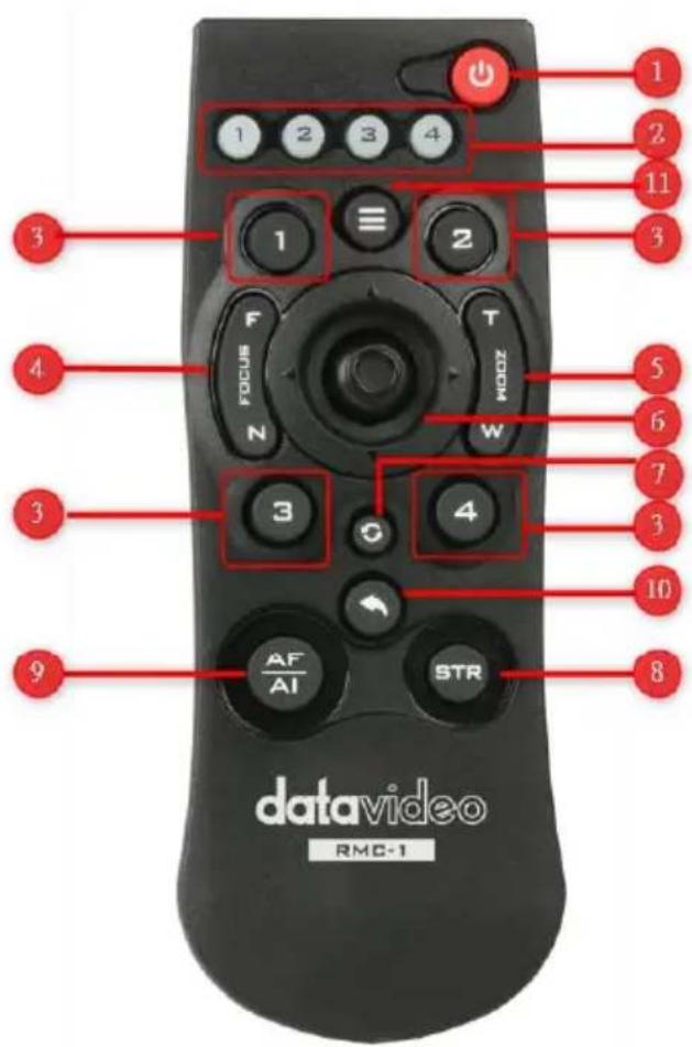
| 1 | Power Button | Power ButtonPress this button once to enter Standby Mode, press it again to enter Normal Mode.Note: The power consumption in Standby Mode is approximately half of the power consumption in Normal Mode. |
| 2 | Camera 1-4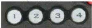 | Camera 1-4The camera 1 to Camera 4 buttons allow you to set your PTC-285 cameras in No.1 to No. 4.Please short-press the button 1 to button 4 to select the camera 1, camera 2, camera 3 or camera 4.Please long-press one of the camera 1 to camera 4 buttons. After that, those four buttons will be lit, at this time, please short-press one of the four buttons to finish the camera number setting. |
| PT | Preset1-4 Buttons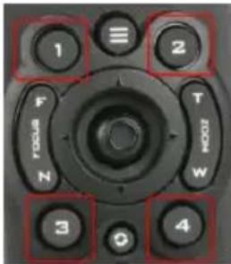 | The Preset buttons 1, 2, 3, and 4 allow you to set up to 4 camera preset settings.How to set the Preset: Please adjust your desired camera parameters and camera lens position in advance. After that, please press the “STR” button which is located on the remoter controller. And then please press your desired Preset Number button (Preset 1 to Preset 4) to set your setting as a Preset.How to recall the Preset: Please press the desired “Preset No.” button (Preset 1 to Preset 4) directly and then the presaved Preset settings will be recalled successfully. |
| 4 | Focus Far/Focus Near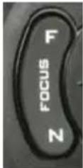 | Focus Far/Focus NearPlease press the “Focus Far” or “Focus Near” button to shift the PTC-285 camera to “Manual” Mode.The “Focus Far” function allows you to focus on the distance.The “Focus Near” function allows you to focus on close distance. |
| 5 | Zoom Tele/Zoom Wide Button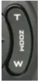 | Zoom Tale/Zoom Wide ButtonThe Zoom Tale/Zoom Wide button allows you to zoom out and zoom in the subject. “Zoom Tale” allows you to zoom in the subject and “Zoom Wide” allows you to zoom out the subject. |
| 6 | Micro Joystick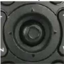 | Micro Joystick: Up/Down/Left/Right/ConfirmPlease move the “Micro Joystick” to the up, down, left and right sides to move the camera lens to the up, down left and right sides. When the OSD menu is turned on, please move the micro joystick to the up side or down side to select different options. Please move the micro joystick to the left or right side to select different setting values. After that, please press the “Micro Joystick” to confirm your selected value. |
| 7 | Reset IP Button | Reset IP ButtonPlease press this button to resume the IP address of the PTC-285 to its default value “192.168.100.88”. |
| b |  | STR ButtonPlease press this button and the “Preset 1 to Preset 4” buttons to save your desired Preset.After you desired setting values and camera lens position are set, please press the “STR” button and then press the button of your desired Preset number from “Preset 1 to Preset 4”. After that, the Preset is set successfully. |
| 9 | AF Auto Focus/AI Auto-Tracking On/Off Button | Auto Focus Button/AI Auto-Tracking On/Off ButtonPlease press this button to turn on the Auto Focus function.Please long-press this button for 2 seconds to turn on or turn off the AI Auto-Tracking function. |
| 10 | Back Button | Back ButtonPlease press the “Back” button to turn the camera head back to the “Home” position. When the OSD menu is opened, you can go back to the previous layer of the OSD menu by pressing the “Back” button. |
| 11 | Menu Button | Menu ButtonPlease press the “Menu” button to open the OSD menu of the PTC-285 camera on the external monitor. |
4.2 OSD Menu
On-Screen Menu allows the user to modify various camera settings. Press [MENU] on the remote control to open the on-screen menu as shown below.
| OSD Menu |
| Exposure |
| Color |
| Image |
| P/T/Z |
| Noise Reduction |
| Setup |
| Communication Setup |
| Information |
| Restore Default |
| 【Home】Enter |
| 【Menu】Exit |
The table below summarizes the main option items and their sub-options.
| Main Options | |||||||
| Exposure | Color | Image | P/T/Z | Noise Reduction | Setup | Communication Setup | |
| Sub-Options | Mode | WB Mode | Luminance | SpeedByZoo m | NR3D-Level | Language | Protocol |
| ExpComp Mode | RG | Contrast | AF-Zone | HDMI RGB Mode | V_Address | ||
| Backlight | BG | Sharpness | AF-Sense | Video Format | V_AddrFix | ||
| Gain Limit | Saturation | Flip-H | L/R Set | Audio Select | Net Mode | ||
| Anti-Flicker | Hue | Flip-V | Display Info | SDI-3G Mode | Baudrate | ||
| Meter | B&W- Mode | Image Freeze | USB UPGRADE | ||||
| DRC | Style | Digital Zoom | VISCA ID | ||||
| Pre Speed | Audio Channel | ||||||
| Pre Zoom Speed | |||||||
| Sub-Options | |
| ARM | Restore?Yes/No |
| SOC | |
| Date | |
| AF | |
| Format | |
| Model | |
| IP | |
| Gateway | |
| NetMask | |
| CTRL SRC | |
Details of all options in the on-screen menu are listed in the table below.
| Main Menu | Sub Menu | Options | Options |
| Exposure | Mode | Auto | |
| Manual | |||
| SAE | |||
| AAE | |||
| Bright | |||
| ExpCompMode | Off | ||
| On | ExpComp | ||
| -7~+7 | |||
| Backlight | Off | ||
| On | |||
| Gain Limit | 0 | ||
| 1 | |||
| 2 | |||
| 3 | |||
| 4 | |||
| 5 | |||
| 6 | |||
| 7 | |||
| 8 | |||
| 9 | |||
| 10 | |||
| 11 | |||
| 12 | |||
| 13 | |||
| 14 | |||
| 15 | |||
| 16 | |||
| 17 | |||
| 18 | |||
| 19 | |||
| 20 | |||
| 21 | |||
| 22 | |||
| Anti-Flicker | Off |
| 50Hz | |
| 60Hz | |
| Meter | Average |
| Center | |
| Smart | |
| Top | |
| DRC | 0 |
| 1 | |
| 2 | |
| 3 | |
| 4 | |
| 5 | |
| 6 | |
| 7 | |
| 8 | |
| Iris | F1.8 |
| F2.0 | |
| F2.4 | |
| F2.8 | |
| F3.4 | |
| F4.0 | |
| F4.8 | |
| F5.6 | |
| F6.8 | |
| F8.0 | |
| F9.6 | |
| F11.0 | |
| Close | |
| Shutter | 1/30 |
| 1/60 | |
| 1/90 | |
| 1/100 | |
| 1/125 | |
| 1/180 | |
| 1/250 | |
| 1/350 | |
| 1/500 | |
| 1/725 | |
| 1/1000 | |
| 1/1500 | |
| 1/2000 | |
| 1/3000 | |
| 1/4000 | |
| 1/6000 | |
| 1/10000 | |
| Gain | 0 |
| 1 | |
| 2 | |
| 3 | |
| 4 |
| 5 | ||
| 6 | ||
| 7 | ||
| 8 | ||
| 9 | ||
| 10 | ||
| 11 | ||
| 12 | ||
| 13 | ||
| 14 | ||
| 15 | ||
| 16 | ||
| 17 | ||
| 18 | ||
| 19 | ||
| 20 | ||
| 21 | ||
| 22 | ||
| Bright | 0 | |
| 1 | ||
| 2 | ||
| 3 | ||
| 4 | ||
| 5 | ||
| 6 | ||
| 7 | ||
| 8 | ||
| 9 | ||
| 10 | ||
| 11 | ||
| 12 | ||
| 13 | ||
| 14 | ||
| 15 | ||
| 16 | ||
| 17 | ||
| Color | WB Mode | Auto |
| Indoor | ||
| Outdoor | ||
| OnePush | ||
| Manual | ||
| VAR | ||
| RG Tuning | 0 | |
| +1 | ||
| +2 | ||
| +3 | ||
| +4 | ||
| +5 | ||
| +6 | ||
| +7 | ||
| +8 |
| +9 | |
| +10 | |
| -10 | |
| -9 | |
| -8 | |
| -7 | |
| -6 | |
| -5 | |
| -4 | |
| -3 | |
| -2 | |
| -1 | |
| BG Tuning | 0 |
| +1 | |
| +2 | |
| +3 | |
| +4 | |
| +5 | |
| +6 | |
| +7 | |
| +8 | |
| +9 | |
| +10 | |
| -10 | |
| -9 | |
| -8 | |
| -7 | |
| -6 | |
| -5 | |
| -4 | |
| -3 | |
| -2 | |
| -1 | |
| Saturation | 60% |
| 70% | |
| 80% | |
| 90% | |
| 100% | |
| 110% | |
| 120% | |
| 130% | |
| 140% | |
| 150% | |
| 160% | |
| 170% | |
| 180% | |
| 190% | |
| 200% | |
| Hue | 0 |
| 1 | |
| 2 | |
| 3 | |
| 4 | |
| 5 | |
| 6 | |
| 7 | |
| 8 | |
| 9 | |
| 10 | |
| 11 | |
| 12 | |
| 13 | |
| 14 | |
| RG | 0~255 |
| BG | 0~255 |
| Color Temp | 2500K |
| 2600K | |
| 2700K | |
| 2800K | |
| 2900K | |
| 3000K | |
| 3100K | |
| 3200K | |
| 3300K | |
| 3400K | |
| 3500K | |
| 3600K | |
| 3700K | |
| 3800K | |
| 3900K | |
| 4000K | |
| 4100K | |
| 4200K | |
| 4300K | |
| 4400K | |
| 4500K | |
| 4600K | |
| 4700K | |
| 4800K | |
| 4900K | |
| 5000K | |
| 5100K | |
| 5200K | |
| 5300K | |
| 5400K | |
| 5500K | |
| 5600K |
| 5700K | ||
| 5800K | ||
| 5900K | ||
| 6000K | ||
| 6100K | ||
| 6200K | ||
| 6300K | ||
| 6400K | ||
| 6500K | ||
| 6600K | ||
| 6700K | ||
| 6800K | ||
| 6900K | ||
| 7000K | ||
| 7100K | ||
| 7200K | ||
| 7300K | ||
| 7400K | ||
| 7500K | ||
| 7600K | ||
| 7700K | ||
| 7800K | ||
| 7900K | ||
| 8000K | ||
| Image | Luminance | 0 |
| 1 | ||
| 2 | ||
| 3 | ||
| 4 | ||
| 5 | ||
| 6 | ||
| 7 | ||
| 8 | ||
| 9 | ||
| 10 | ||
| 11 | ||
| 12 | ||
| 13 | ||
| 14 | ||
| Contrast | 0 | |
| 1 | ||
| 2 | ||
| 3 | ||
| 4 | ||
| 5 | ||
| 6 | ||
| 7 | ||
| 8 | ||
| 9 | ||
| 10 | ||
| 11 |
| 12 | |||
| 13 | |||
| 14 | |||
| Sharpness | Auto | ||
| 0 | |||
| 1 | |||
| 2 | |||
| 3 | |||
| 4 | |||
| 5 | |||
| 6 | |||
| 7 | |||
| 8 | |||
| 9 | |||
| 10 | |||
| 11 | |||
| 12 | |||
| 13 | |||
| 14 | |||
| 15 | |||
| Flip-H | Off | ||
| On | |||
| Flip-V | Off | ||
| On | |||
| B&W-Mode | Off | ||
| On | |||
| Style | Default | ||
| Norm | |||
| Bright | |||
| PC | |||
| P/T/Z | SpeedByZoom | Off | |
| On | |||
| AF-Zone | Front | ||
| Top | |||
| Center | |||
| Bottom | |||
| AF-Sense | High | ||
| Low | |||
| Normal | |||
| L/R Set | STD | ||
| REV | |||
| Display Info | Off | ||
| On | |||
| Image Freeze | On | ||
| Off | |||
| Digital Zoom | Off | ||
| 2x | |||
| 4x | |||
| 8x |
| 16x | ||
| Pre Speed | 1 | |
| 2 | ||
| 3 | ||
| 4 | ||
| 5 | ||
| 6 | ||
| 7 | ||
| 8 | ||
| 9 | ||
| 10 | ||
| 11 | ||
| 12 | ||
| 13 | ||
| 14 | ||
| 15 | ||
| 16 | ||
| 17 | ||
| 18 | ||
| 19 | ||
| 20 | ||
| 21 | ||
| 22 | ||
| 23 | ||
| 24 | ||
| Pre Zoom Speed | 0 | |
| 1 | ||
| 2 | ||
| 3 | ||
| 4 | ||
| 5 | ||
| 6 | ||
| 7 | ||
| Noise Reduction | NR3D-Level | Auto |
| Off | ||
| 1 | ||
| Noise Reduction | NR3D-Level | 2 |
| 3 | ||
| 4 | ||
| 5 | ||
| 6 | ||
| 7 | ||
| 8 | ||
| Setup | Language | 繁體 |
| EN | ||
| 中文 | ||
| русский | ||
| HDMI RGB Mode | HDMI | |
| DVI |
| Video Format | 1080P25 | |
| 720P50 | ||
| 1080P60 | ||
| 1080P50 | ||
| 1080I60 | ||
| 1080I50 | ||
| 1080P30 | ||
| 720P60 | ||
| 1080P29.97 | ||
| 1080I59.94 | ||
| 1080P59.94 | ||
| 720P59.94 | ||
| 4KP29.97 | ||
| 4KP59.94 | ||
| 4KP25 | ||
| 4KP30 | ||
| 4KP50 | ||
| 4KP60 | ||
| Audio Select | MIC | |
| LINE IN | ||
| SDI-3G Mode | LEVEL-A | |
| LEVEL-B | ||
| USB UPGRADE | Off | |
| On | ||
| VISCA ID | By DIP | |
| By OSD | ||
| Audio Channel | Stereo | |
| Mono | ||
| Communication Setup | Protocol | VISCA |
| PELCO-D | ||
| PELCO-P | ||
| Auto | ||
| V_Address | 1 | |
| V_AddrFix | Off | |
| On | ||
| Net Mode | Serial | |
| Paral | ||
| Baudrate | 38400 | |
| 2400 | ||
| 4800 | ||
| 9600 | ||
| Information | ARM | |
| SOC | ||
| Date | ||
| AF | ||
| Format | ||
| Model | ||
| IP | ||
| GateWay | ||
| NetMask | ||
| CTRL SRC | ||
| Restore Default | Restore? |
Note: For the “Audio Channel” option in the OSD menu, if the “mono” is selected, the data for the left audio channel will be copied to the right audio channel and they will output together. If the audio source is “mono”, only the left audio channel will output the audio.
4.3 Professional Jargon Explanations of the OSD
Menu
There are some professional jargons or nouns which are shown in the OSD menu of the PTC-285T camera, please refer to this section for realizing those jargons.
- Speed by Zoom: When this function is turned “ON”, at the time when the zoom-in/zoom out is beginning or it is about to reach the zoom-in/zoom-out limit or users want to stop zooming in/zooming out, the zoom-in/zoom-out speed of the camera lens will be reduced linearly. When this function is turned “OFF”, the zoom-in/zoom-out speed will be consistent no matter when the camera zoom-in is started or stopped.
- Flip-H: This is the “Horizontal Flipping”. When “ON” is selected, the screen which is shot by the camera will flip horizontally. If “OFF” is selected, the screen will be shown in normal direction.
- Flip-V: This is the “Vertical Flipping”. When “ON” is selected, the screen which is shot by the camera will flip vertically. If “OFF” is selected, the screen will be shown in normal direction.
- L/R Set: If the “REV” is selected for this option, the panning direction of the PTC-285T camera lens will be opposite to the direction which is controlled by the remote controller. If the “STD” is selected for this option, the panning direction of the camera lens will be the same as the direction which is selected by the remote controller.
5. Instruction for installation
Note: Only mount the bracket on formwork or concrete surface. Do NOT mount the bracket on plasterboard.
Step 1 – DIP Switch Setting
Set the Mirror option to H+V mode.
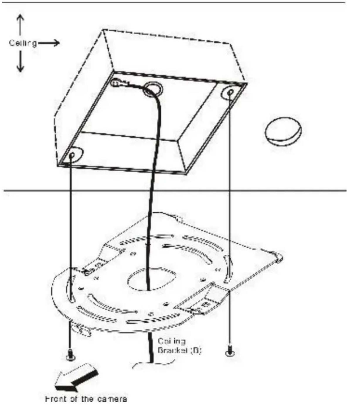
Step 2 – One End of Retaining Wire
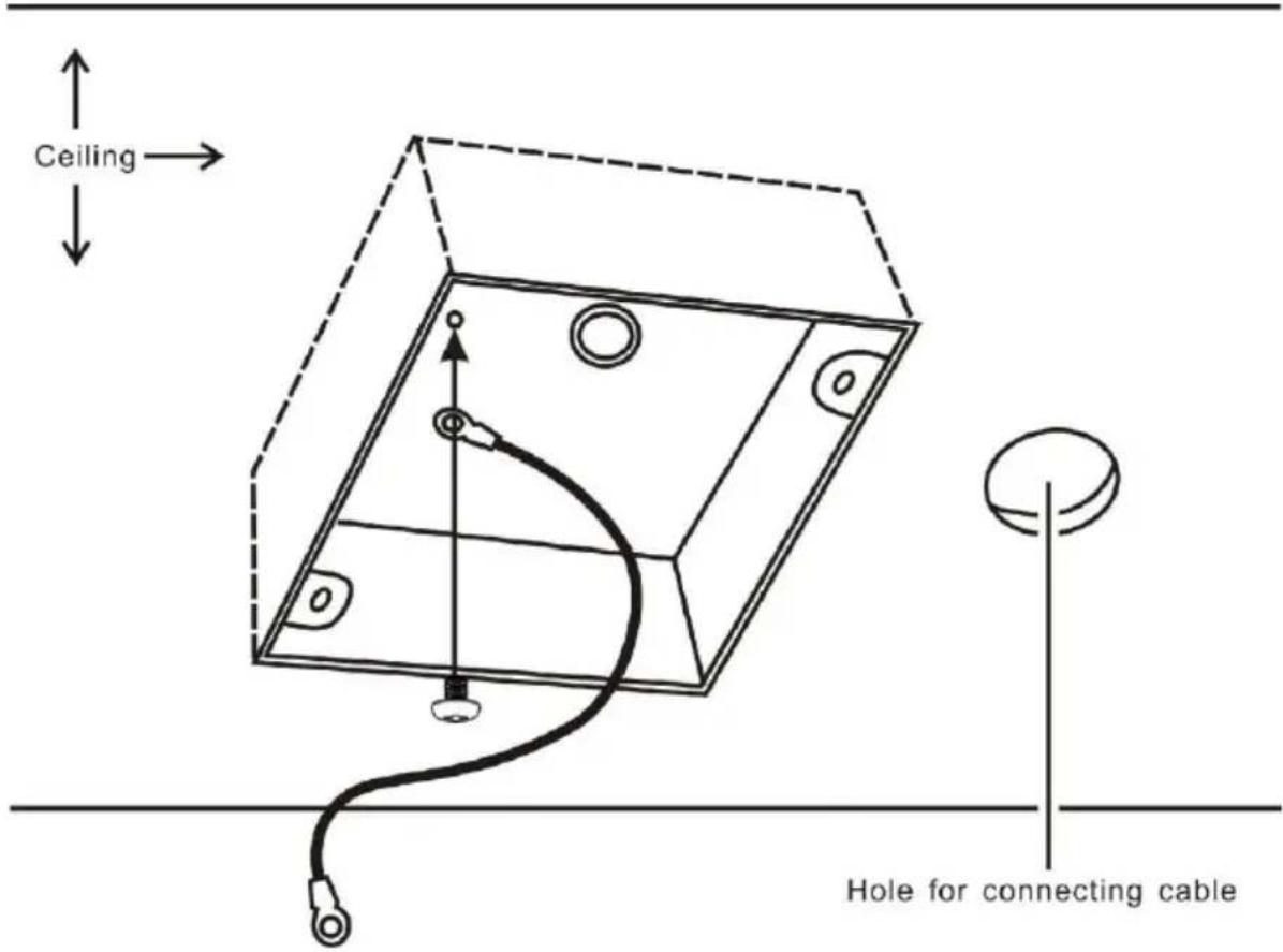
Attach the retaining wire to the junction box mounted on the ceiling by screwing one end of the retaining wire into a screw hole in the junction box with a screw (not supplied) as shown in the diagram below.
Step 3 – Ceiling Bracket (B)
Again, as illustrated in the diagram below, screw a ceiling bracket (B) into the junction box mounted on the ceiling.
Make sure the screw holes of the ceiling bracket (B) are aligned with the holes on the junction box.
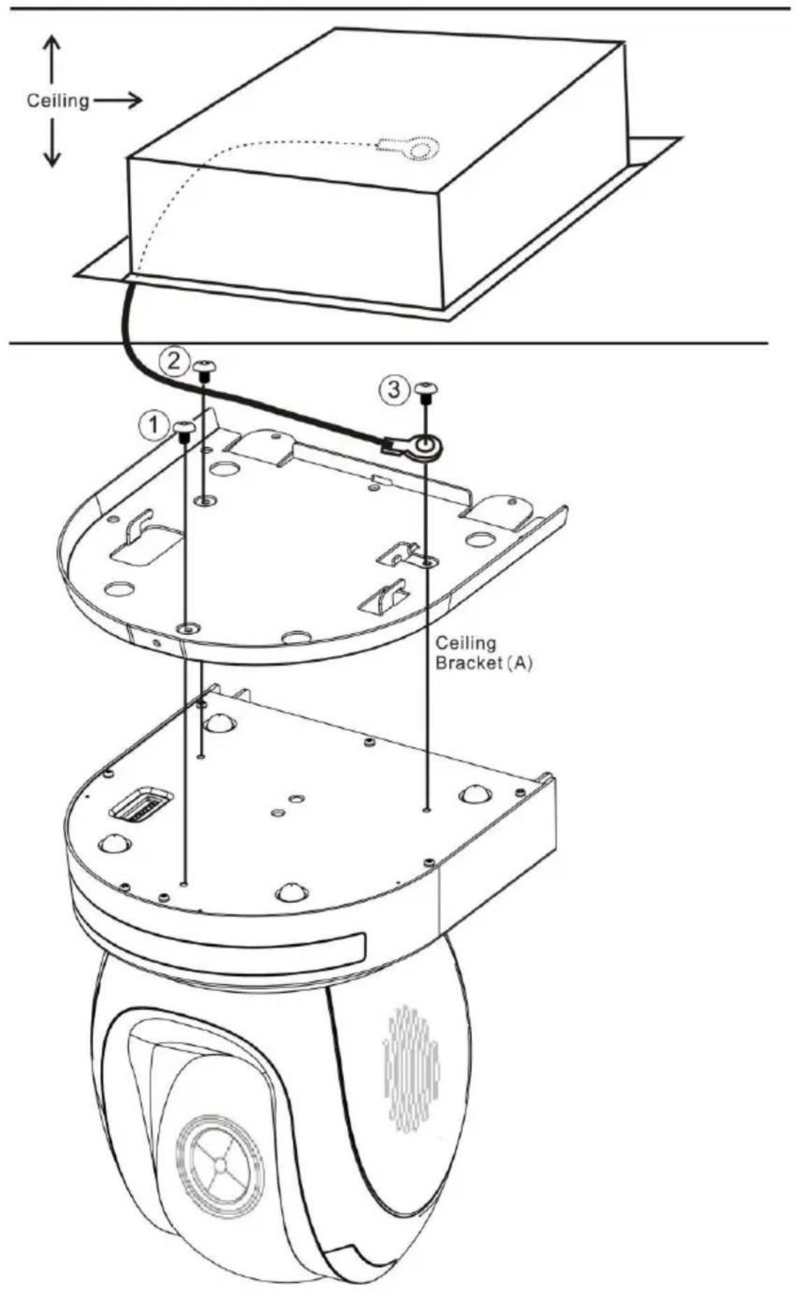
Step 4 – Ceiling Bracket (A) and Camera
- Screw ceiling bracket (A) into the bottom of the camera using three screws.
- Position the screws as shown in the diagram below.
- Align the screw holes on the bottom of the camera with those in the ceiling bracket.
- Insert the screws into the corresponding screw holes in the numbered order.
• The other end of the retaining wire is screwed into the screw hole #3. - Securely tighten all three screws.
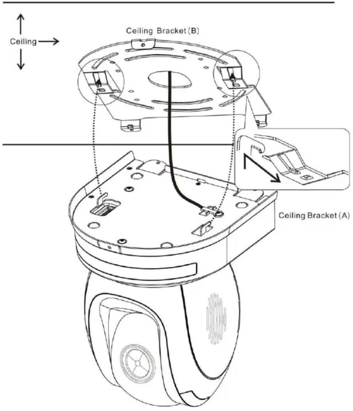
Step 5 – Mount Camera to Ceiling
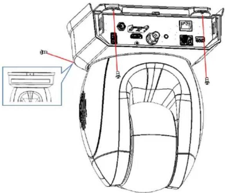
Step 6 – Screw to Fix Camera
Fix the camera by screwing three screws into the corresponding screw holes as shown in the diagram below.
Step 7 – Cable Connection
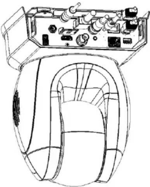
Connect the cables to the connectors located on the rear of the camera.
natural_image
Technical line drawing of a mechanical device interior with no visible text or symbols6. Network Connection
The Ethernet port on the back panel of your PTC-285T allows you to connect to camera from the PC/Laptop with Static or dynamic IP addresses. To access and modify these network settings, you will need to login to the camera's web interface.
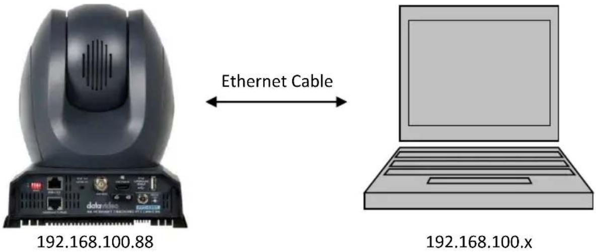
If this is your first time using the device, please note that the camera's default IP address is 192.168.100.88.
Set up direct connection between the camera and your PC/laptop as depicted in the diagram below; remember to manually assign an IP address of 192.168.100.X to your PC/laptop.
On your PC/laptop, open a web browser and in the address bar, enter the camera's default IP address, 192.168.100.88 then press the ENTER key which should take you to login page of the web interface.
datavideo
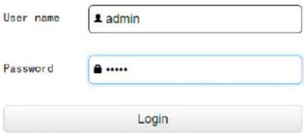
The default login credentials are:
- User Name: admin
- Password: admin
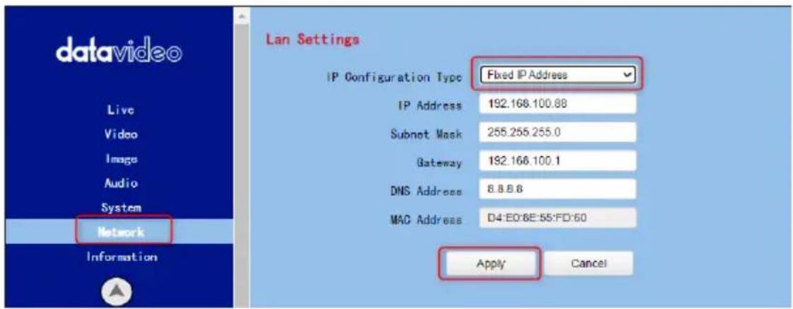
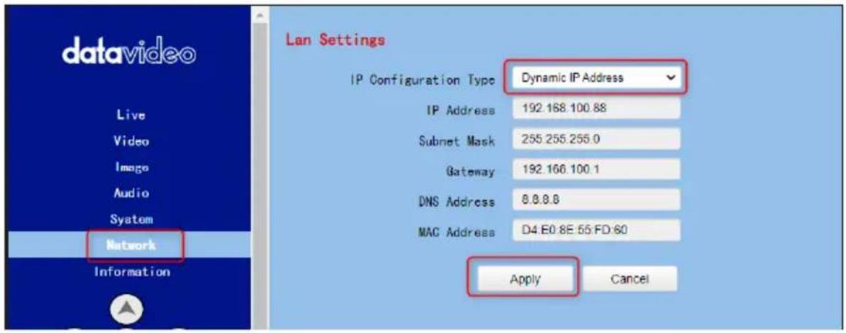
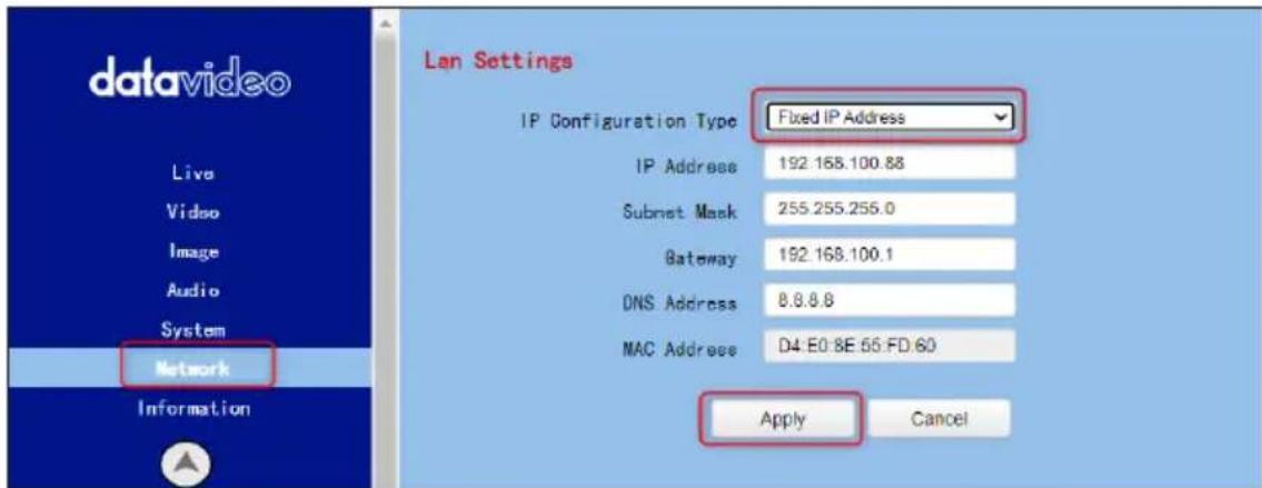
After users login into the web user interface successfully, please click the "Network" option and then please click the "IP Configuration Type" drop-down menu from the "Lan Settings" area to modify the connection type of the camera to DHCP or Fixed IP. If the "Fixed IP Address" is selected, it will be set in fixed IP mode. If the "Dynamic IP Address" is selected, it will be set in DHCP mode. After the setting is finished, please click the "Apply" button for completing the setting.
In following two chapters, we will show you how to enable DHCP and Static IP modes in two separate sections.
6.1 DHCP Mode
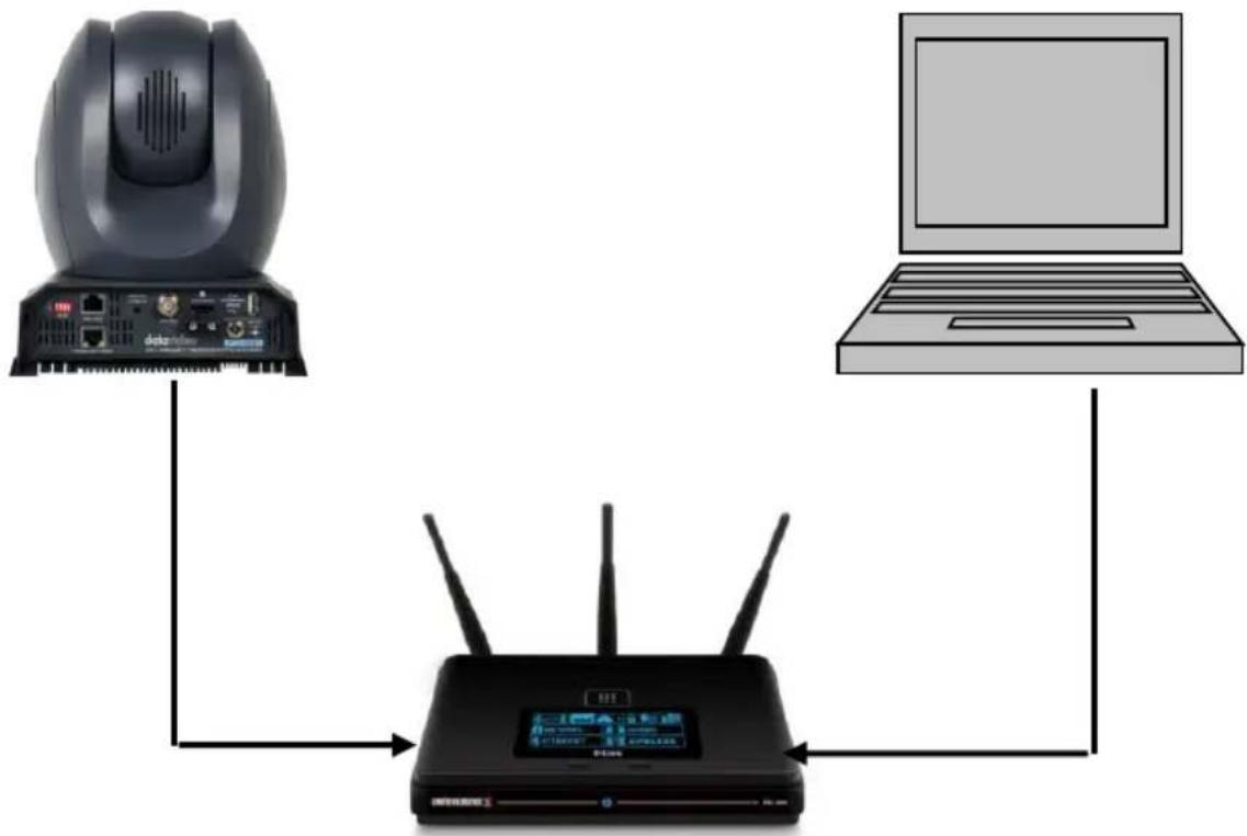
Dynamic Host Configuration Protocol (DHCP) is a network protocol that enables a server to automatically assign an IP address to a network device from a defined range of numbers configured for a given network. The diagram below illustrates a DHCP network connection example.
flowchart
graph TD
    A["Device 1"] --> B["Router"]
    C["Device 2"] --> B
    D["Laptop"] --> B
    B --> E["User Interface"]
In order to enable the DHCP mode of the camera, please select "Dynamic IP Address" from the "IP Configuration Type" drop-down menu for assigning a dynamic IP address to PTC-285T by the router. After that, please click the "Apply" button to save the new settings and then please reboot the PTC-285T.
6.2 Static IP
A static IP address is a fixed address manually assigned to PTC-285T. First please select “Fixed IP Address” from the “IP Configuration Type” drop-down menu and then please enter an IP address for the camera, the subnet mask and the gateway IP.
Note: Never assign an address that ends in .0 or .255 as these addresses are typically reserved for network protocols. An address to the very start of the IP pool is also not recommended as it is always reserved for the router.
After the Static IP address is set, please click the "Apply" button for saving new settings and then please reboot the PTC-285T.
6.3 DVIP
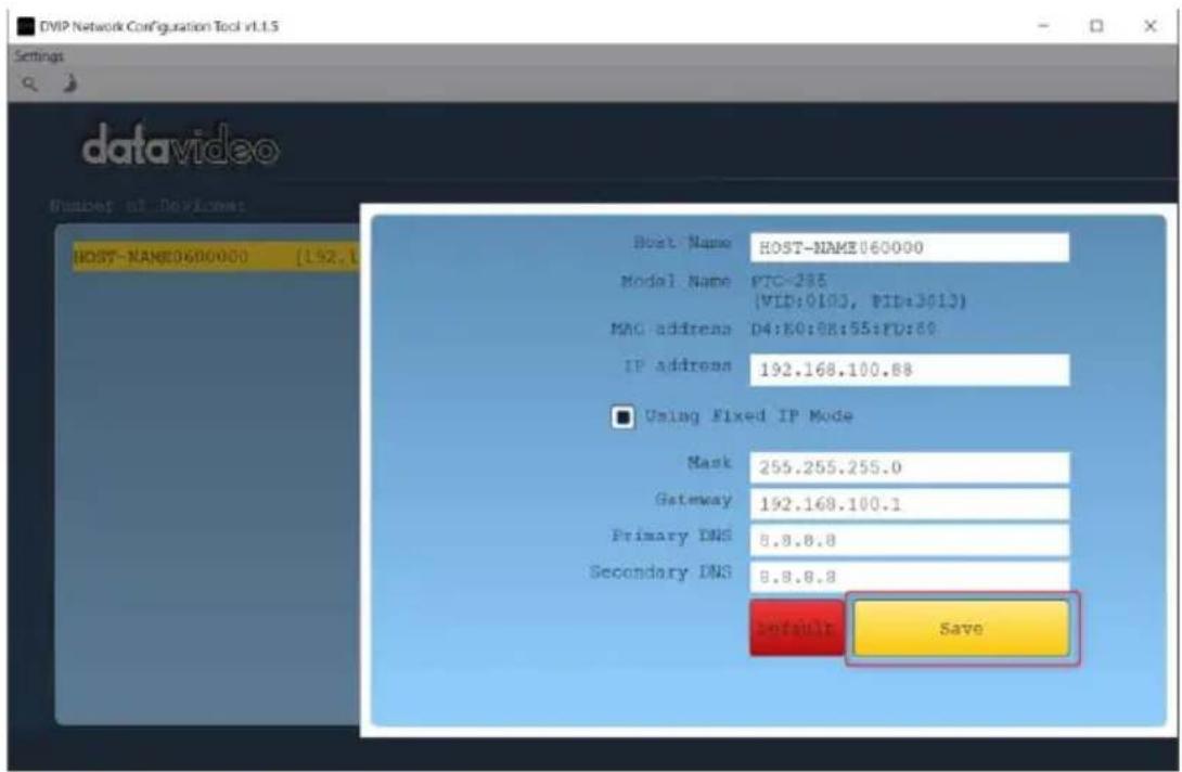
DVIP is a special network configuration software tool designed for DVIP device search on the same network and configuring device network settings such as Hostname, DHCP mode, IP address, subnet mask, gateway IP, and primary and secondary DNS.
Depending on your operating system, download DVIP Configuration Tool from the respective sites listed as follows:
PC: https://www.microsoft.com/en-us/p/dvip-network-config/9p6gtz839k6s?activetab=pivot%3Aoverviewtab
Android:
https://play.google.com/store/apps/details?id=com.datavideo.dvipnetconfig&hl=en_US
iOS: https://itunes.apple.com/tw/app/dvip-network-config/id1177895983?mt=8
After you've installed the DVIP Network Configuration Tool, follow the steps outlined below to scan for online DVIP devices and configure their corresponding settings.
Step 1: Open the DVIP Network Configuration Tool and then select the connected Ethernet option from the “Network interface” pop-up window. After that please press the “OK” button
![datavideo Select N_ ? × Network Interface: [192.168.2.16] 乙水網路 OK Cancel](/content/2026/05/837136/images/2f895e7aba7069c3a8c500824902b87bb0461559816cc7b8b9b27e9e92a0a4f7.jpg)
Step 2: After the Network interface is selected, the DVIP Network Configuration Tool interface will be shown as following diagram.
![DVIP Network Configuration Tool v1.1.5 Settings datavideo Number of Devices: HOST-NAME0600000 [192,168,100.89] [D4:E0:8E:55:F0:60]](/content/2026/05/837136/images/eb894fc047a7e98665ae815e92d670c1ec6f3e397a868be3d94ab3750904d8c6.jpg)
Step 3: Please press "HOST NAME" and then the network settings pop-up window will be shown.
![DVIP Network Configuration Tool v1.1.5 Settings datavideo Number of Devices: HOST NAME0600000 [192.168.100.88] [D4:80:8E:55:FD:60]](/content/2026/05/837136/images/c70057f0fc39c0ed4363136992739bc11b00ef8b4c65857b5d075fa31f8ba2ca.jpg)
Step 4: Users can click "Host Name" column for changing the device name. Users can also click each setting column for changing value if it is needed. After that, please press "Save" for saving those settings. Users can also press "Default" for resuming those settings to factory default value.
7. How to Use PTC-285T's AI Auto Tracking
The Datavideo PTC-285T is a 4K HDBaseT Tracking PTZ Camera that allows you to use the AI Auto-Tracking function in a single-person or multi-person scenario. The PTC-285T provides two AI Auto-Tracking modes including single-person and multi-person tracking modes. Please refer to the following sections for operating the Auto-Tracking function of the PTC-285T.
7.1 How to turn on the AI Auto-Tracking Function
Please follow the following steps for turning on PTC-285T's AI Auto-Tracking function.
- Please use PTC-285's remote controller to turn on the AI Auto-Tracking

function. Please long-press the "AF/AI" button of the remote controller for 2 seconds.
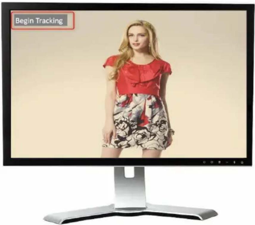
- At this time, PTC-285T's AI Auto-Tracking function will be turned on. There is a reminder "Begin Tracking" that will be shown on the OSD of the external monitor which is connected to the PTC-285T. This means that the AI Auto-Tracking function is turned on successfully.
7.2 How to turn off the AI Auto-Tracking Function
Please follow the following steps for turning off PTC-285T's AI Auto-Tracking function.
- Please use PTC-285T's remote controller to turn on the AI Auto-Tracking

function. Please long-press the "AF/AI" button of the remote controller for 2 seconds.
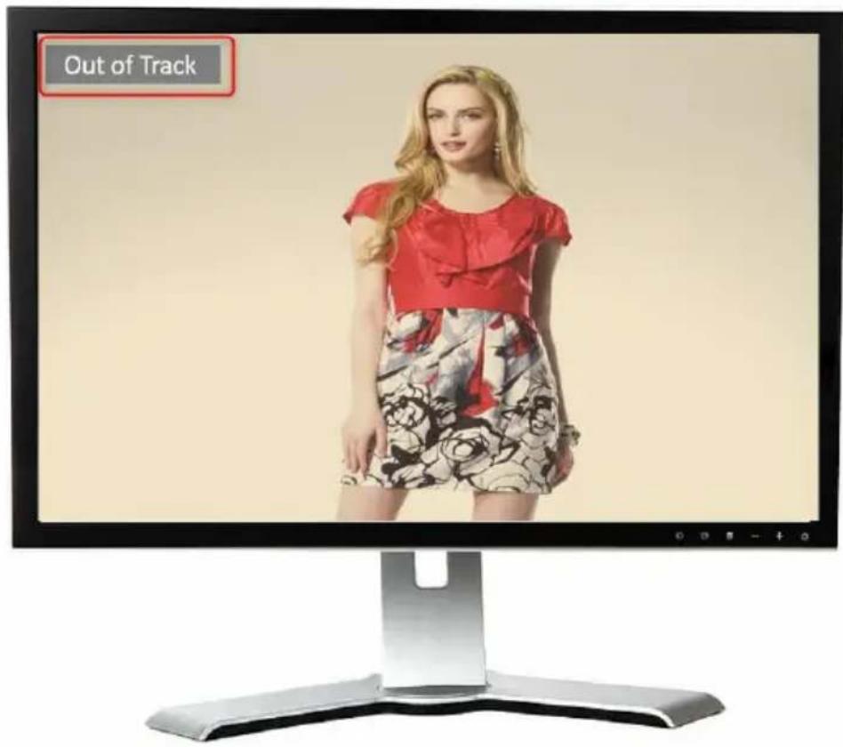
- At this time, PTC-285T's AI Auto-Tracking function will be turned off. There is a reminder "Out of Track" that will be shown on the OSD of the external monitor which is connected to the PTC-285T. This means that the AI Auto-Tracking function is turned off successfully.
7.3 Single-Person Scene Auto-Tracking Mode
When applying in the single-person scenario, please follow the following steps for using the “Single-Person Scene Auto-Tracking Mode” of the PTC-285T.

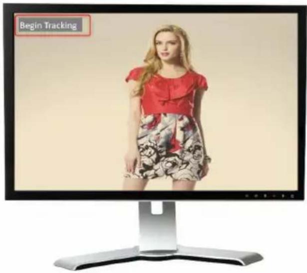
- Please long-press the "AF/AI" button of the remote controller for 2 seconds. After the reminder "Begin Tracking" is shown on the OSD of the external connected monitor, it means that the "Single-Person Scene Auto-Tracking Mode" of the PTC-285T camera is turned on successfully.
-
At this time, the PTC-285T will lock the target and track it directly.
-
When the tracking target is lost, the PTC-285T will stay at the position where the tracking target is lost for a few seconds and then go back to the initial position. When the tracking target appears again, the PTC-285T will track the target automatically.
7.4 Multi-Person Scene Auto-Tracking Mode
When applying in the multi-person scenario, please follow the following steps for using the “Multi-Person Scene Auto-Tracking Mode” of the PTC-285T.

-
Please long-press the "AF/AI" button of the remote controller for 2 seconds. After the reminder "Begin Tracking" is shown on the OSD of the external connected monitor, it means that the "Multi-Person Scene Auto-Tracking Mode" of the PTC-285T camera is turned on successfully.
-
When tracking in the multi-person scene, there is a green frame that will be shown on the external monitor for you to choose your desired tracking target.
Please use the "Micro Joystick" from the remote controller to select your desired tracking target. After the tracking target is selected, please press
the "Micro Joystick" to start the tracking.

natural_image
Computer monitor displaying a group of six business professionals in professional attire, one highlighted with a green box (no text or symbols visible on the image itself)- After the tracking is started, the green frame will disappear which is shown in the following diagram.

natural_image
Computer monitor displaying six business professionals in professional attire, no visible text or symbols on the image itself.- During the process of the "Multi-Person Scene Auto-Tracking" Mode, if you
want to change your tracking target, please use the "Micro Joystick" from the remote controller directly to select your new tracking target. After that, a green frame will be shown, please select your new tracking target and

then press the "Micro Joystick" from the remote controller. And then it will start to track the new target.

natural_image
Computer monitor displaying five business professionals in professional attire, one highlighted with a green box (no text or symbols visible)- When the tracking target is lost, the PTC-285T will stay at the position where the tracking target is lost for a few seconds and then go back to the initial position. When the tracking target appears again, the PTC-285T will track the target automatically.
Note: Please pay attention that when the AI Auto-Tracking function is turned on, the PTC-285T will not receive the control commands from other controllers, which is the normal situation.
8. Web User Interface
The web based user interface allows you to set and control your PTC-285T devices.
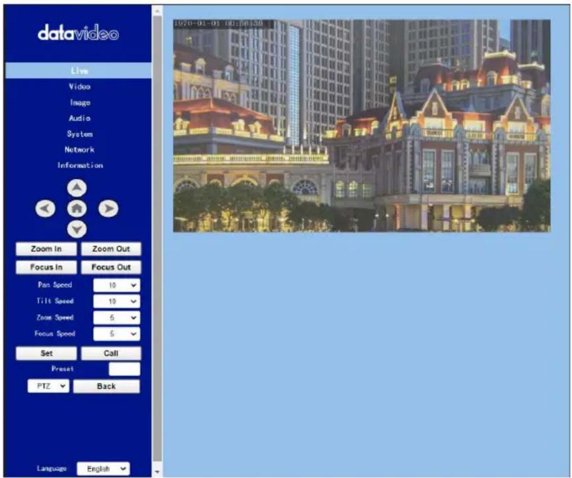
8.1 Live
Live option allows users to preview the image which is shot by the PTC-285T in a real-time basis. Please click the “Live” option and then users can preview the image which is shot by the PTC-285T camera from the preview window.
8.2 Video
"Video" option allows users to set various parameters including Video Format, Encode Level. Moreover, it also allows users to set the Encode Protocol, Resolution, Bit Rate, Frame Rate, I Key Frame Interval and Bit Rate Control for the First stream and Second stream. The main interface for the Video option is shown in the following diagram.
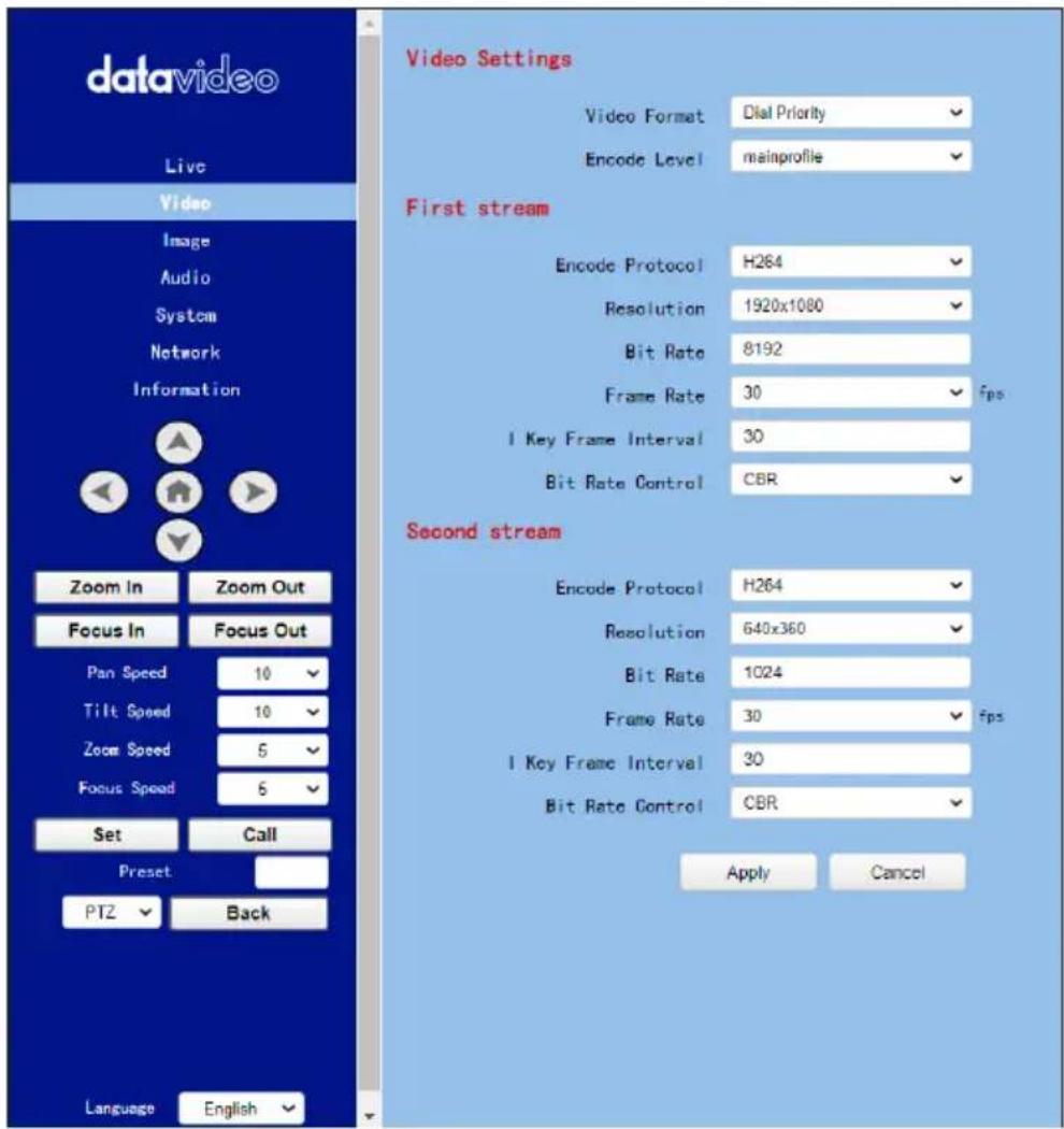
Please see the following section for realizing the descriptions for each item for the Video option.
| Items | Descriptions | |
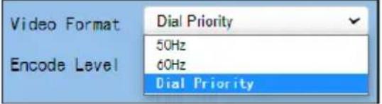 | Video FormatIt can support three video formats including 50Hz(PAL), 60Hz(NTSC) and Dial Priority. | |
| 50Hz (PAL): If you select this option, the maximum frame rate per second (FPS) for the streaming video will be 50.60Hz (NTSC): If you select this option, the maximum frame rate per second for the streaming video will be 60.Dial Priority: If you select this option, the maximum frame rate per second will be 30, and it is possible that the parameters including the video format and frame rate will be affected by the camera OSD menu settings.Note:1. If you want to use the PTC-285T camera to connect to some Datavideo switchers which support the interlace format only such as the HS-1300, SE-120 MU and SE-650, please remember to select the “Dial Priority” option as your video format.2. If the 50Hz or the 60Hz is selected for the PTC-285T web UI, the SDI or the HDMI output format of the PTC-285T camera will be fixed at 1080p 50/60. | ||
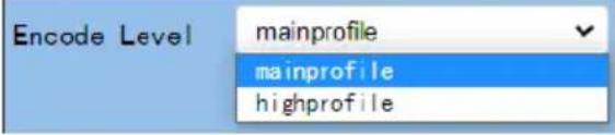 | Encode LevelIt allows users to select needed Encode Level from two Encode Levels including mainprofile and highprofile. | |
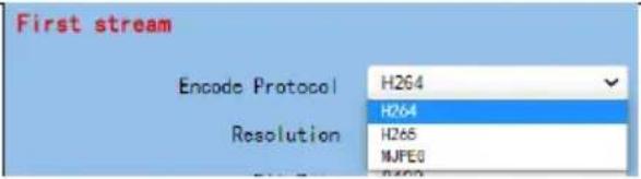 | Encode Protocol (First Stream & Second Stream)It allows users to select three Encode Protocols including H.264, H.265 and MJPEG for the “First Stream” and “Second Stream”. | |
Resolution for the first stream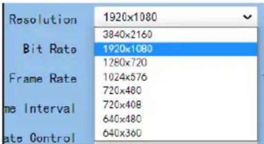 | Resolution (First Stream & Second Stream)There are two drop-down menus including the resolution for the First Stream and the resolution for the Second Stream for users to select different resolution.When the resolution is higher, the image will become clearer. However, it will occupy more network bandwidth. | |
Resolution for the second stream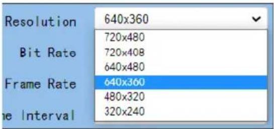 | ||
 | Bit Rate (First Stream & Second Stream)It allows users to determine the Bit Rate range by themselves. The range for the Bit Rate for the first stream is from 32-51200kbps. The range for the Bit Rate for the second stream is from 32-20480kbps.Note: If the network bandwidth is too narrow and the Bit Rate setting is too high, it will cause that the video streaming can not be transferred normally and it will cause a poor visual effect for viewers. | |
 | ||
 | Frame Rate (First Stream & Second Stream)Users can set the Frame Rate from the drop-down menu by themselves. The range is from 1 to 60. When the Frame Rate value is higher, the image will be smoother. When the Frame Rate value is lower, it will cause an unsmooth image. | |
 | I Key Frame Interval (First Stream & Second Stream)It allows users to set the interval between two I frames. When the interval is larger, the response speed from the viewing window will be lower. | |
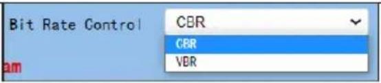 | Bit Rate Control (First Stream & Second Stream)There are two ways for Bit Rate Control including the CBR and VBR.CBR: The video encoder will encode the video according to the default speed.VBR: The video encoder will encode the video by adjusting the encoding speed according to the default value in order to achieve best image quality. | |
 | Apply KeyAfter all of the options are set, please click the “Apply” key and then all of the changes will be effective. | |
| Items | Descriptions |
| Cancel | Cancel KeyIf the “Cancel” key is pressed, all of the changes will not take effect. |
8.2.1 How to Connect the PTC-285T to a Datavideo Switcher after a 60FPS/50FPS Video Streaming (Take the HS-1300 as an example)
When you select the 50Hz or the 60Hz option from the 「Video」→「Video Settings」 drop-down menu in the PTC-285T web UI for streaming videos, the PTC-285T HDMI/SDI output will be fixed at 1080p 50/60. However, the Datavideo HS-1300 switcher supports the 1080i video format only rather than the 1080p video format. So, when you want to connect the PTC-285T to the HS-1300 switcher, it is necessary for you to set the PTC-285T again in order to make sure that the video formats for the PTC-285T and the HS-1300 are consistent. Moreover, it can assure that the input screen that is received by the HS-1300 can be displayed correctly. Please follow following steps for setting the PTC-285T and the HS-1300.
● Take the adjustment to 1080i59.94 as an example
Step 1. At first, please press the "MENU" button which is located on the PTC-285T remote controller to open the OSD menu.
Step 2. After the OSD menu is opened, please move down the "Microjoystick"
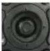
to select the "Setup" option, and then please press the "Microjoystick"
to enter the "Setup" option.
Step 3. In “Video Format” option, please move the “Microjoystick” to the left or right side to select 1080i60, 1080i59.94 or 1080i50 video format.

Step 4. Please press the "MENU" button which is located on the control panel of the HS-1300 switcher to open its OSD menu.

Step 5. Please use the down arrow button to select the "Setup" option.
Step 6. Please use the right arrow button to select "Standard" "1080i59.94", and then please press the "Enter" button to enter this option for further adjustment.
Step 7. If the format for the "Standard" is not 1080i59.94, please use the up

arrow button and down arrow button / which are located on the control panel to adjust the video format to 1080i59.94.
Step 8. Please select your desired "Standard" value and then press the "ENTER" button again to confirm your selection.
Step 9. Please press the right arrow button again to select the "Save Setup" option.
Step 10. Please use the left arrow button and the right arrow button to select the "Yes" button and then press the "ENTER" button again to save the setting.

Step 11. After the setting is saved, please press the "MENU" button to exit to the previous menu and to exit the OSD menu of the HS-1300. The "Standard" option setting for the HS-1300 is finished until this step.
Step 12. Please open the web UI of the PTC-285T.
Step 13. Please click the "Video" option, and then please select "Dial Priority" from the "Video Format" drop-down menu.
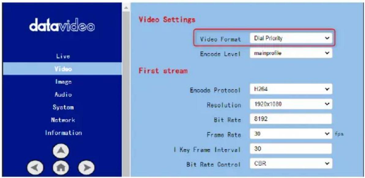
Step 14. Please click the "Apply" button Apply
Step 15. Please click the "Reboot" button in the "System" option to reboot the PTC-285T.
Step 16. After the PTC-285T is rebooted, please use an SDI cable to connect from the 3G-SDI interface which is located on the rear panel of the PTC-285T to the SDI IN interface which is located on the rear panel of the HS-1300, or you can use an HDMI cable to connect from the HDMI interface which is located on the rear panel of the PTC-285T to the HDMI IN interface which is located on the rear panel of the HS-1300. After that, you can see the image which is shot by the PTC-285T is displayed in the MULTIVIEW window of the HS-1300 correctly.
For SDI: The SDI IN 1 to SDI IN 4 interfaces which are located on the rear panel of the HS-1300 represent the MULTIVIEW window's Input 1 to Input 4.
For HDMI: The HDMI IN 1 to HDMI IN 2 interfaces which are located on the rear panel of the HS-1300 represent the MULTIVIEW window's Input 5 to Input 6.
Note: Datavideo's SE-650, HS-1200 MU and HS-1300 switchers support 1080i video format only. So, the 1080p video format is not supported by the above-mentioned switchers. If you want to connect the PTC-285T camera to the SE-650 or the HS-1200 MU switcher, please remember to select the “Dial Priority” item from “Video→ Video Format” in the PTC-285T web UI. Moreover, please use the OSD menu of the PTC-285T camera and the OSD menu of the above-mentioned switchers to adjust them in the same video standard before
connecting to prevent the video format incompatible issue and the issue that the video that is shot by the PTC-285T can not be displayed normally in the MULTIVIEW window of the above-mentioned switchers.
8.3 Image
The “Image” option allows users to see the image that is shot by the PTC-285T from the preview window. Moreover, users can adjust many parameters including Brightness, Saturation, Contrast, Sharpness and Hue from this interface by using sliders. The main interface of the Image option is shown as following diagram.
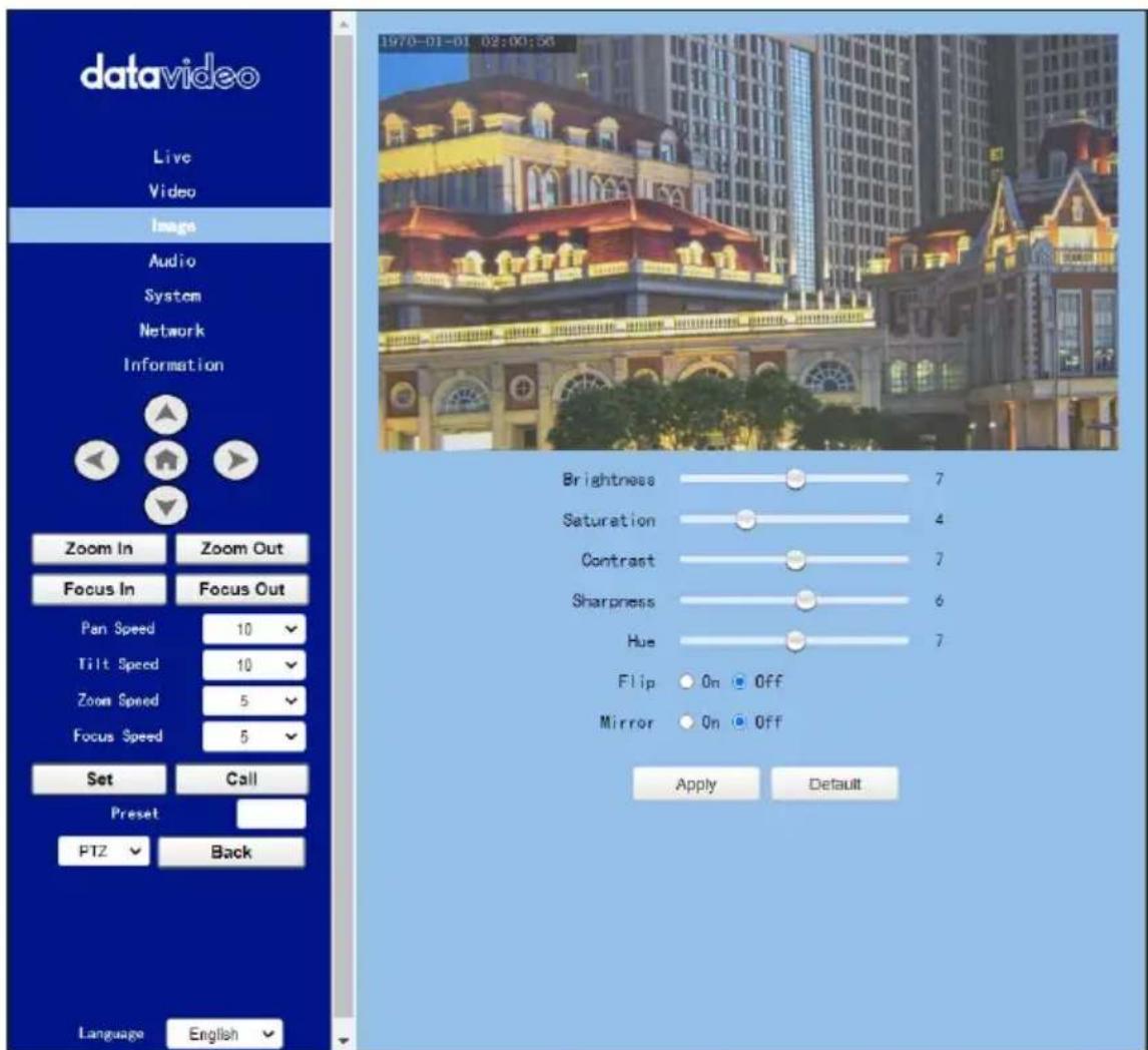
● Brightness: This option allows users to adjust the Brightness. Please use the slider for adjusting the Brightness.
Saturation: This option allows users to adjust the Saturation. Please use the slider for adjusting the Saturation. After the adjustment is finished, please click the "Apply" button and then it is set successfully.
Saturation: This option allows users to adjust the Saturation. Please use the slider for adjusting the Contrast. After the adjustment is finished, please click the "Apply" button and then it is set successfully.
● Sharpness: This option allows users to adjust the Sharpness. Please use the slider for adjusting the Sharpness. After the adjustment is finished, please click the "Apply" button and then it is set successfully.
- Hue: This option allows users to adjust the Hue. After the adjustment is finished, please click the "Apply" button and then it is set successfully.
- Flip: Please check the checkbox of the "Flip On" option and then please click the "Apply" button for flipping the image that is shot by the camera.
Mirror: Please check the checkbox of the "Mirror On" option Mirror ☐ On and then please click the "Apply" button for mirroring the image that is shot by the camera.
Default: Please click the "Default" button Default for restoring the settings in this page to factory default value.
8.4 Audio
The Audio option allows users to set the audio related parameters. The main interface of the audio option is shown as following diagram.
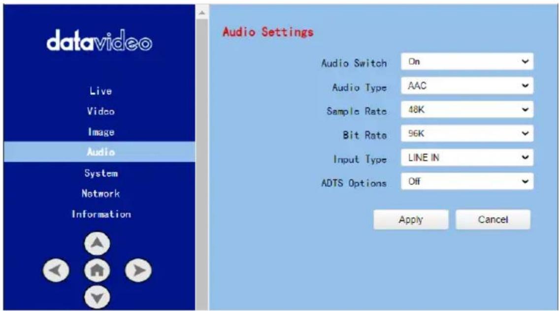
Please see following section for realizing the descriptions for each item for the Audio option.
| Items | Descriptions |
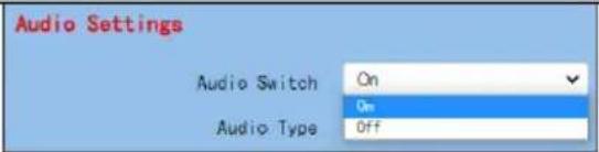 | Audio SwitchThis option allows users to turn on or turn off the input of the audio source. |
 | Audio TypeThis allows users to select the encoding format of the input audio.The default audio type is the AAC format. |
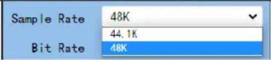 | Sample RateThis drop-down menu allows users to select desired sample rate for the input audio source. There are two sample rate including 44.1K and 48K for users to select. |
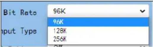 | Bit RateThis drop-down menu allows users to select their desired Bit Rate. |
 | Input TypeThis option allows users to select the audio signal input way. Users can input the audio by external connected MIC or by LINE IN. |
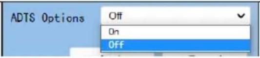 | ADTS OptionThis drop-down menu allows users to turn on or turn off the ADTS. |
| Apply | Apply KeyAfter all of the options are set,please click the “Apply” key and thenall of the changes will be effective. |
| Cancel | Cancel KeyIf the “Cancel” key is pressed, all ofthe changes will not take effect. |
8.5 System
This System option allows users to select functions including Reboot, Factory default, User/Guest Name and Password. The main interface of the System option is shown as following diagram. Please pay attention that the “Factory Default” option resumes the OSD menu rather than the Web UI to its factory default settings.
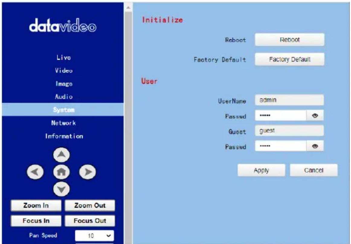
Please see following section for realizing the descriptions for each item for the System option.
| Items | Descriptions | |
 | RebootPress the “Reboot” button and then a reminder dialogue box will appear, please press the “OK” button for rebooting the camera. | |
 | Factory DefaultPress the “Factory Default” button and then a reminder dialogue box will appear, please press the “OK” button for resuming PTC-285T’s OSD menu to its factory default value. | |
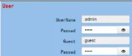 | UserThere are several items including Username, Password, Guest and Password for users to set the username and password for user and guest. After the setting is finished, please press the “Apply” button for applying the setting.The default username/Password for user is “admin/admin”.The default Username/Password for Guest is “guest/guest”. | |
 | Apply KeyAfter all of the options are set, please click the “Apply” key and then all of the changes will be effective. | |
| Cancel | Cancel KeyIf the “Cancel” key is pressed, all of the changes will not take effect. | |
8.6 Network
The Network option allows users to set many network related functions. The main interface of the Network option is shown as following diagram.
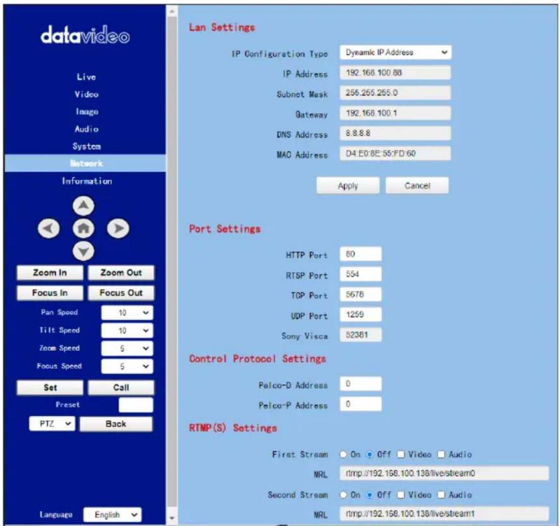
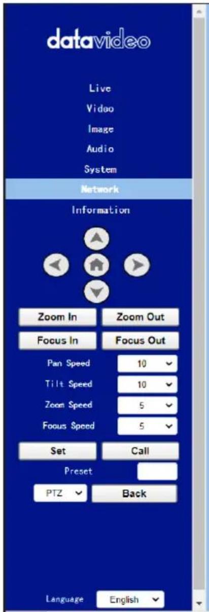
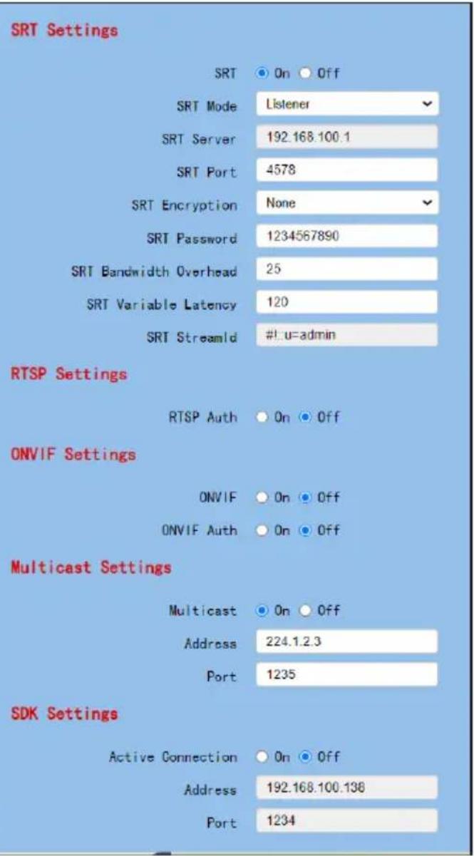
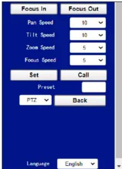
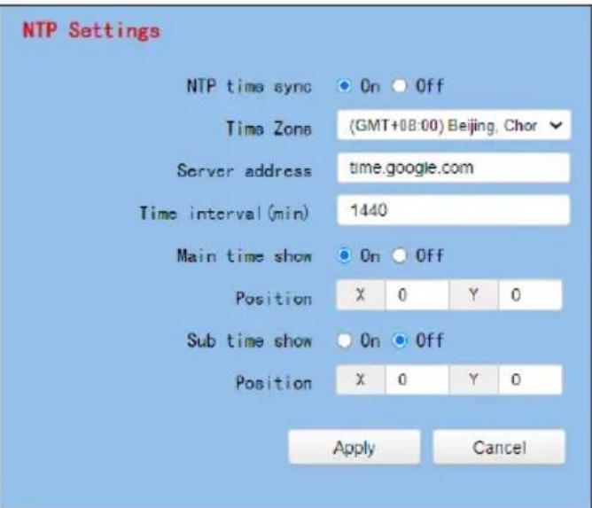
Please see following section for realizing the descriptions for each item for the Network option.
| Items | Description | |
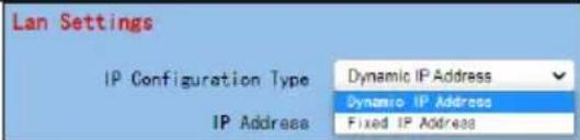 | IP Configuration TypeThis drop-down menu allows users to select the Static IP or DHCP mode. If the “Fixed IP Address” is selected, it will operate in static IP mode. If the “Dynamic IP Address” is selected, it will operate in DHCP mode. | |
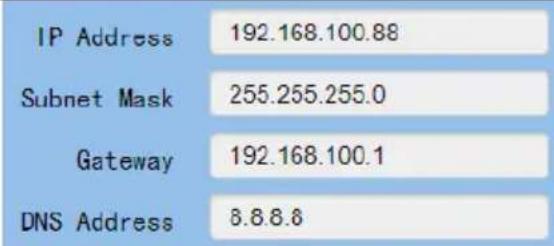 | IP Address/SubnetMask/Gateway/DNS AddressIf the fixed IP address is selected, users can set related parameters manually. After the settings are finished, please click the “Apply” button and then those settings will take effect. | |
 | MAC AddressThis is the MAC Address and it can not be changed by users. | |
 | HTTP PortThis is the HTTP Port and the default port No. is 80. | |
 | RTSP PortThis is the RTSP Port and the default port No. is 554. | |
| TCP Port 5678 | TCP PortThis is the TCP Port No. and the default port No. is 5678. | |
| UDP Port 1259 | UDP PortThis is the UDP Port No. and the default port No. is 1259. | |
| Sony Visca 52381 | Sony ViscaThis is the Sony Visca Port No. and the default No. is 52381. | |
| Pelco-D Address 0 | Pelco-D AddressThis option allows users to set the Pelco-D address, the range is from 0 to 254. | |
| Pelco-P Address 0 | Pelco-P AddressThis option allows users to set the Pelco-P Address, the range is from 0 to 31. | |
| First Stream On Off Video AudioMRL http://192.168.100.138/live/stream0 | First StreamThis option allows users to determine whether they want to turn on/turn off the First Stream streaming. Moreover, this option can turn on/turn off the streaming of video and audio separately. | |
| MRLPlease copy the RTMP server address and streaming key from the streaming platform and then paste them into this MRL column. After that, please press the “Apply” button for starting the streaming successfully. | ||
 | Second StreamThis option allows users to determine whether they want to turn on/turn off the Second Stream streaming. Moreover, this option can turn on/turn off the streaming of video and audio separately.MRLPlease copy the RTMP server address and streaming key from the streaming platform and then paste them into this MRL column. After that, please press the “Apply” button for starting the streaming successfully. | |
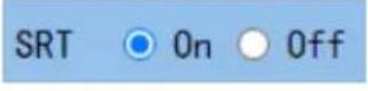 | SRT On/OffThis allows users to turn on or turn off the SRT streaming function. | |
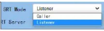 | SRT ModeWhen the SRT ON/OFF is turned on, you can select “Caller” or “Listener” mode from this drop-down menu. | |
| SRT Server | 192.166.100.1 | SRT ServerThis SRT server provides an IP address for you to enter into your SRT streaming software when you are using the SRT streaming function and the PTC-285T camera is set as Listener mode and the SRT streaming software such as the Vmix is set as the Caller mode. |
| SRT Port | 4578 | SRT PortThis is the SRT port and the default port No. is 4578. |
| SRT Encryption | NoneNone | SRT EncryptionWhen the SRT function is turned on, this option allows users to select their desired SRT Encryption way. There are three encryption ways including AES-128, AES-192 and AES-256 for users to select. |
| SRT Password | AES-128AES-192AES-256 | |
| SRT Password | 1234567890 | SRT PasswordWhen the SRT encryption way is set, it is needed for users to use this password. The default value is 1234567890 and this password can change by users. |
| SRT Variable Latency | 120 | SRT Variable LatencyThis column allows you to set the transmission latency of the SRT streaming. You can set the latency within the range of 20 to 8000. |
| SRT Bandwidth Overhead | 25 | SRT Bandwidth OverheadThe Bandwidth Overhead is a |
| Items | Description |
| percentage which is set according to the network link. You can multiply this percentage value by the encoder-encoded video and audio total bitrates to get the maximum overhead which is allowed by the Bandwidth overhead. This value plus the total value of the video and audio bitrates is the maximum value of the current SRT transmission bandwidth, which is the maximum bandwidth of this SRT channel. The purpose of the bandwidth overhead is to transfer the control message data packet which accompany the SRT streaming. Moreover, it also includes the retransmission for all of the media packets. If the network link condition is worse, more exchanges for the control message data packets and more retransmissions for the media data packets will be needed. And you need to set a higher Bandwidth Overhead value. | |
| SRT StreamId #!::u=admin | SRT Stream ID EnableThis option allows you to turn on or turn off the SRT Stream ID. The Stream ID is an information which can be exchanged between the SRT Caller and the SRT Listener when the SRT connection is established. This Stream ID information allows the SRT Listener to determine whether the connection from a certain SRT Caller should be accepted or not. |
| Items | Description | |
| RTSP AuthOnOff | RTSP AuthThis option allows users to turn on or turn off the authentication of the RTSP streaming. | |
| ONVIFOnOff | ONVIFThis option allows users to turn on or turn off the ONVIF function. | |
| ONVIF AuthOnOff | ONVIF AuthThis option allows users to turn on or turn off the ONVIF authentication. | |
| MulticastOnOff | MulticastThis option allows users to turn on or turn off the Multicast function. | |
| Address224.1.2.3 | AddressThis option is the address of Multicast. The default value is 224.1.2.3 | |
| Port1235 | PortThis is the Port No. of the Multicast. The default No. is 1235. | |
| Items | Description |
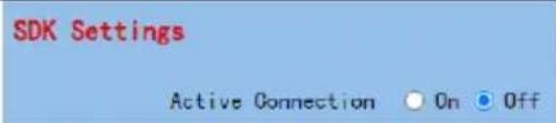 | SDK SettingsThis allows users to turn on or turn off the Active Connection of the SDK Settings. |
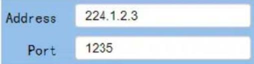 | Address/PortThis is the Address and Port of the SDK Settings. The Address is 192.168.100.138. The Port No. is 1234. |
 | NTP Time SyncThis option allows users to turn on or turn off the NTP Time Sync function. |
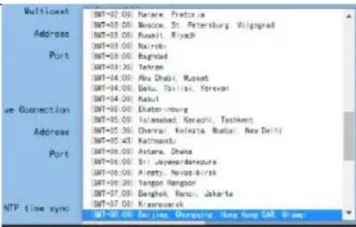 | Time ZoneThis option allows users to select their time zone. |
 | Server AddressThis option provides Google NTP server for you to do the time calibration. |
 | Time IntervalThis option allows users to set the time interval for the time calibration. |
 | Main Time Show/PositionThis option allows users to open or close the time display function for the main time. Moreover, users can enter different X coordinate and Y coordinate positions to determine the position for showing the time on the screen. (The allowable setting range is from 0 to 100). |
 | Sub Time Show/PositionThis option allows users to open or close the time display function for the sub time. Moreover, users can enter different X coordinate and Y coordinate positions to determine the position for showing the time on the screen. (The allowable setting range is from 0 to 100). |
 | Apply KeyAfter all of the options are set, please click the “Apply” key and then all of the changes will be effective. |
 | Cancel KeyIf the “Cancel” key is pressed, all of the changes will not take effect. |
8.7 Information
In the “Information” option, users can change the device name by themselves. Moreover, users can also see the messages including software version and webware version. The main interface of the Information option is shown as following diagram
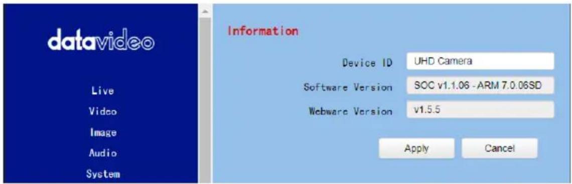
Please see following section for realizing the descriptions for each item for the information option.
| Items | Descriptions | |
| Device ID | UHD Camera | Device IDThis column allows users to determine the device ID by themselves. What they have to do is to enter their desired device ID and then click the “Apply” button. |
| Software Version | SOC v1.1.06 - ARM 7.0.06SD | Software VersionThis option can show current software version. |
| Webware Version | v1.5.5Apply | Webware VersionThis is the version of the web-based control UI.Apply KeyAfter all of the options are set, please click the “Apply” key and then all of the changes will be effective. |
| Cancel | Cancel KeyIf the “Cancel” key is pressed, all of the changes will not take effect. | |
8.8 The PTZ Control Area of the Web UI
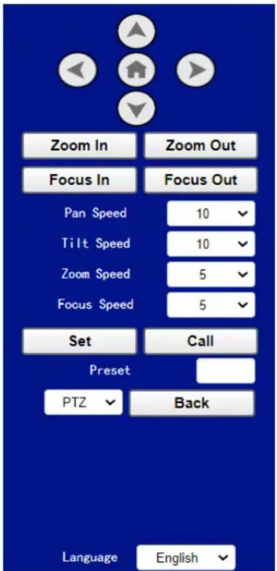
PTC-285T camera's PTZ control area in the Web UI allows users to control the directions, Zoom-In, Zoom-Out, Focus Near and Focus Far parameters for the PTZ camera lens. Moreover, users can also adjust the panning, tilting speed, preset setting and preset calling functions. The PTZ control area is shown as following diagram.
| Items | Descriptions | |
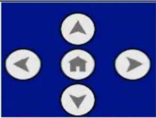 | UP/Down/Left/Right/Home KeysUsers can click the up, down, left and right keys and the PTZ camera lens will rotate to assigned direction. If the Home key  pressed, the camera lens will return back to the initial position automatically.If this Home key is used with the “Back” key, when the “OSD” is selected and the Back key is clicked, the OSD menu will be shown on the external connected screen and users can use the up, down, left and right keys on the Web UI to control the camera. pressed, the camera lens will return back to the initial position automatically.If this Home key is used with the “Back” key, when the “OSD” is selected and the Back key is clicked, the OSD menu will be shown on the external connected screen and users can use the up, down, left and right keys on the Web UI to control the camera. | |
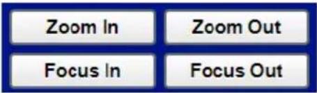 | Zoom In/Zoom Out/Focus In/Focus OutClick “Zoom In” or “Zoom Out” for zooming in or zooming out the camera lens.Click the “Focus In” or “Focus Out” for Focusing Near or Focusing Far the camera lens. | |
 | Pan SpeedThe “Pan Speed” allows users to adjust the rotation speed of the PTZ camera lens. The allowable setting range is from 1 to 24. The larger the number, the faster the PTZ camera lens will rotate. | |
 | Tilt SpeedThe “Tilt Speed” allows users to adjust the vertical rotation speed of the camera lens.The allowable setting range is from 1 to 20.The larger the number, the faster the PTZ camera lens will rotate. | |
 | Zoom SpeedThe “Zoom Speed” allows users to adjust the Zoom In/Zoom Out speed of the PTZ camera lens. The allowable setting range is from 0 to | |
| 7. The larger the number, the faster the PTZ camera lens will rotate. | ||
 | Focus SpeedThe “Focus Speed” allows users to adjust the “Focus Near” and “Focus Far” speed of the PTZ camera lens. The allowable setting range is from 0 to 7. The larger the number, the faster the PTZ camera lens will rotate. | |
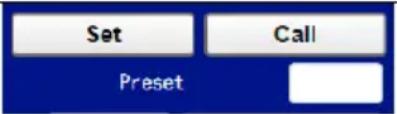 | Set and Call PresetsThe PTC-285T provides 255 presets (0-254) for users to set.Users can use “Set” button to set the preset position and users can use the “Call” button to recall the pre-saved presets. | |
 | OSD/PTZ Drop-Down MenuPress the OSD option from the web UI allows camera to call the OSD menu immediately. If the PTZ is selected after the OSD menu is shown, the OSD menu will disappear and the screen will go back to the scene that is shot by the camera. | |
 | Language Drop-Down MenuUsers can use this drop-down menu for selecting four different languages including Traditional Chinese, русский, English and Simplified Chinese. | |
9. How to Use the Web UI to Set and Call Presets
Please follow following steps for setting and recalling the presets.
● How to Set Preset
- Please adjust your desired camera parameters and camera lens positions in advance.
- Please enter your desired preset number in the "Preset" column

- Please click the "Set" button and then the preset is set successfully.
● How to Recall Preset
- Please enter the preset number that you want to recall into the "Preset"
column. - Please click the "Call" button Call and then the preset is recalled successfully.

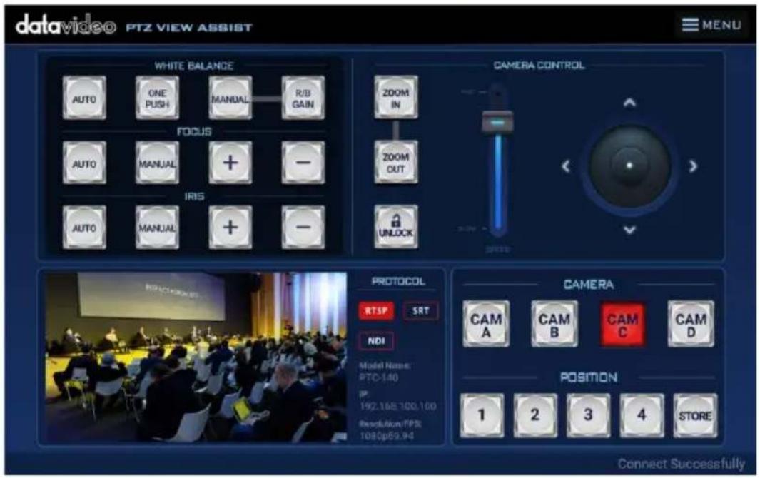
10. Control the Camera by the PTZ View Assist App
Datavideo provides PTZ View Assist App for you to control up to 4 PTC-285T cameras by using Android or iOS handset. What you have to do is to set your handset or tablet in the same LAN with the PTZ View Assist App by the static IP address, and then you can control various functions of the camera by the Wi-Fi connection. Please download the PTZ View Assist App for the Android or iOS platform by using the following addresses.
Note: The Datavideo PTZ View Assist App can be operated only in DVIP mode. So, please remember to adjust the PTC-285T camera to the DVIP mode before using the Datavideo PTZ View Assist App.
For the Android device: Please go to "Google Play" and then search for the "PTZ View Assist". Finally, please download and install it.
For the iOS device: Please go to "App Store" and then search for the "PTZ View Assist". Finally, please download and install it.

11. DIP Switch Settings
11.1 DIP Switch SW1
The DIP Switch SW1 can be found at the bottom of the camera, where the user is allowed to set the camera's VISCA ID, enable remote control, select the video resolution, and configure how the video mode can be selected.
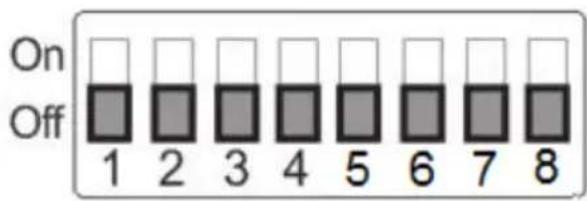
| DIP SW 1/2/3 | VISCA ID |
| (1,2,3) = (ON,OFF,OFF) | VISCA-ID 1 |
| (1,2,3) = (OFF,ON ,OFF) | VISCA-ID 2 |
| (1,2,3) = (ON ,ON ,OFF) | VISCA-ID 3 |
| (1,2,3) = (OFF,OFF,ON) | VISCA-ID 4 |
| (1,2,3) = (ON ,OFF,ON) | VISCA-ID 5 |
| (1,2,3) = (OFF,ON ,ON) | VISCA-ID 6 |
| (1,2,3) = (ON ,ON ,ON) | VISCA-ID 7 |
| DIP SW 4 | Remote Control Protocol |
| Not Connected | Not Connected |
| DIP SW 5/6/7 | Resolution |
| (5,6,7) = (OFF,OFF,OFF)000 | 1920 x 1080i 59.94 |
| (5,6,7) = (ON,OFF,OFF)100 | 1920x1080i50 |
| (5,6,7) = (OFF,ON,OFF)010 | 1920 x 1080p 59.94 |
| (5,6,7) = (ON,ON,OFF)110 | 1920 x 1080p 50 |
| (5,6,7) = (OFF,OFF,ON)001 | 3840 x 2160p 29.97 |
| (5,6,7) = (ON,OFF,ON)101 | 3840 x 2160p 25 |
| (5,6,7) = (OFF,ON,ON)011 | 3840 x 2160p 59.94 |
| (5,6,7) = (ON,ON,ON)111 | 3840 x 2160p 50 |
| DIP SW 8 | Video Mode Selection Method |
| ON | Video mode selectable by DIP switch only |
| OFF | Video mode selectable by menu |
11.2 DIP Switch SW2 (IRID)
The IRID DIP Switch can be found on the rear panel of the PTC-285T camera. This DIP switch allows the user to assign an ID number to the camera so that the user can navigate between the cameras by pressing the CAMERA SELECT buttons.
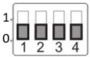
| DIP SW 1/2 | Camera Select Function (IR Remote Control) – Camera ID Assignment |
| (1,2) = (0,0) | CAM1 (IR) |
| (1,2) = (1,0) | CAM2 (IR) |
| (1,2) = (0,1) | CAM3 (IR) |
| (1,2) = (1,1) | CAM4 (IR) |
| * DIP SW 3/4 should be always OFF. | |
12. How to Play the RTSP Stream by the VLC Player
Please follow following steps for playing the RTSP streaming by using the VLC Player.
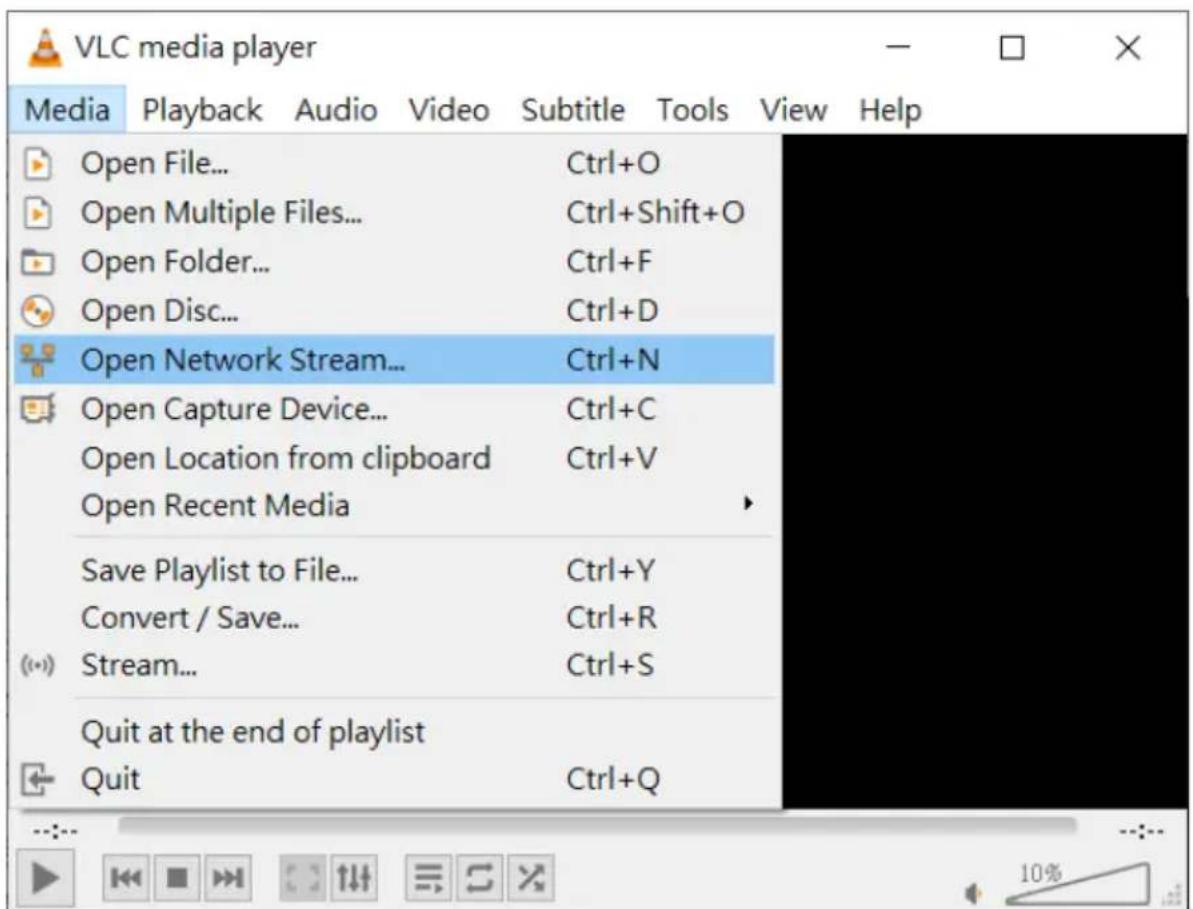
- Please open the VLC Player.
- Please click "Media->Open Network Stream".
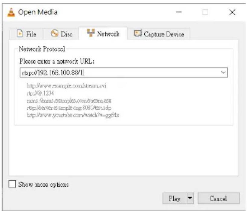
- Please enter the RTSP address.
rtsp://ip address: port No./1 (first stream).
rtsp://ip address: port No./2 (second stream).
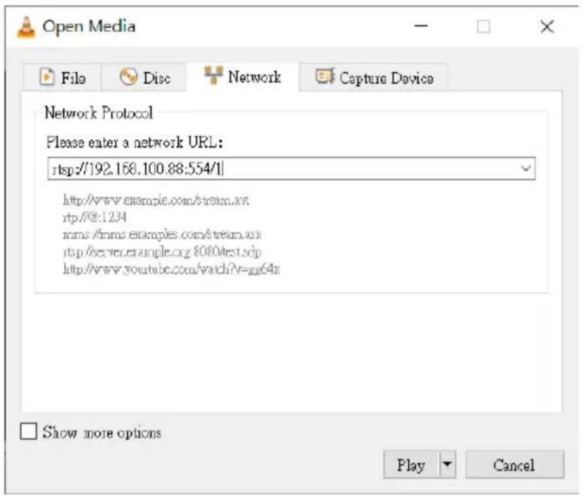
4. Please click "Play" button.
Note: The default port No. of the RTSP is 554, if the default http port of the camera is 80, it is no need for users to enter the port No.
13. How to Play the Multicast by the VCL Player
The RTP Multicast allows users to view the camera image remotely by specific video player such as the VLC Player.
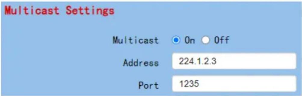
Please follow following steps for playing the RTP Multicast in the VLC Player.
- Download VLC media player from the link https://www.videolan.org.
- Open VLC, click "Media" → "Open Network Stream" then enter rtp://224.1.2.3:1235 to view the video streaming.
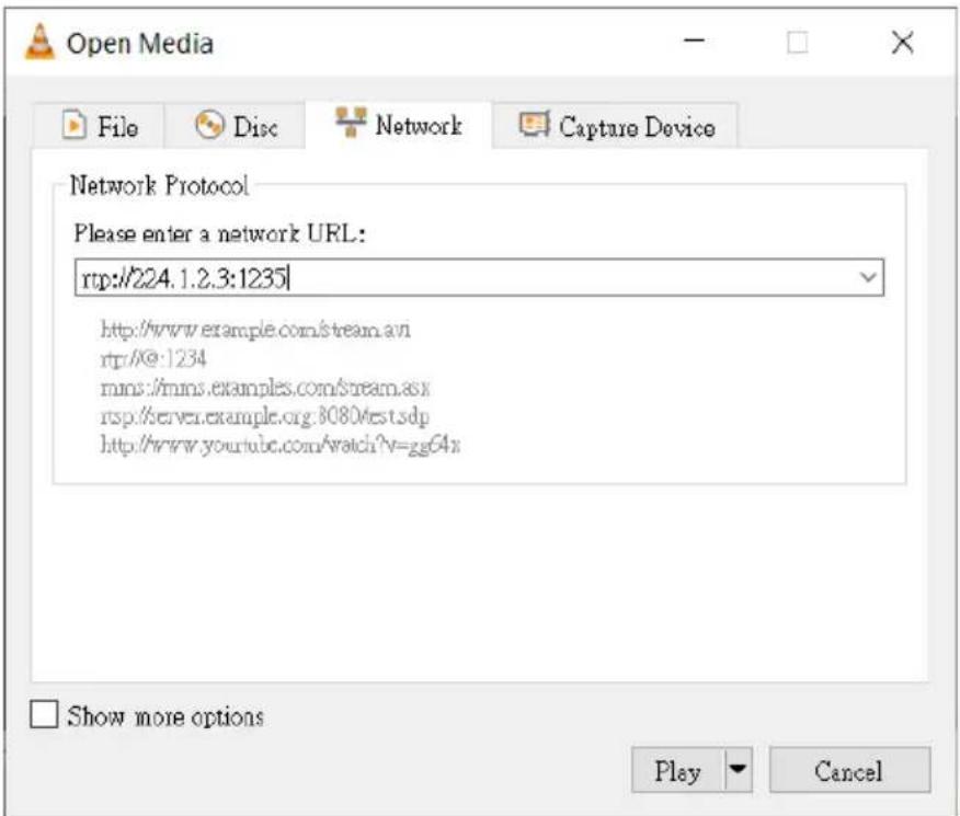
- Click the "Play" button to start viewing the video stream.
14. How to Stream to Facebook
Please follow following steps for streaming to Facebook Streaming platform.
● Use Facebook Live Producer for Streaming
1. Please go to Facebook Live website
https://www.facebook.com/formedia/solutions/facebook-live , and thenplease click “Go Live Now” button which is shown in the following diagram.
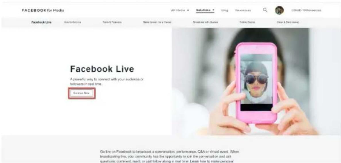
Note: Facebook Live limits each stream to 8 hours.
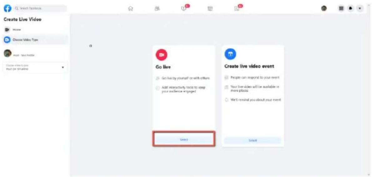
- Please click the "Select" button from the "Go live" option which is shown in the following diagram.
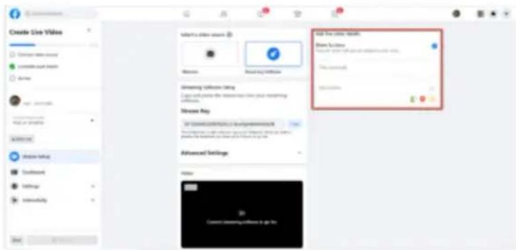
- Please select the "Streaming Software" option, and then please enter the title and description of your live-streaming video in the "Title" and "Description" columns. Moreover, you can determine whether you want to share your live-streaming video to your Facebook Story.
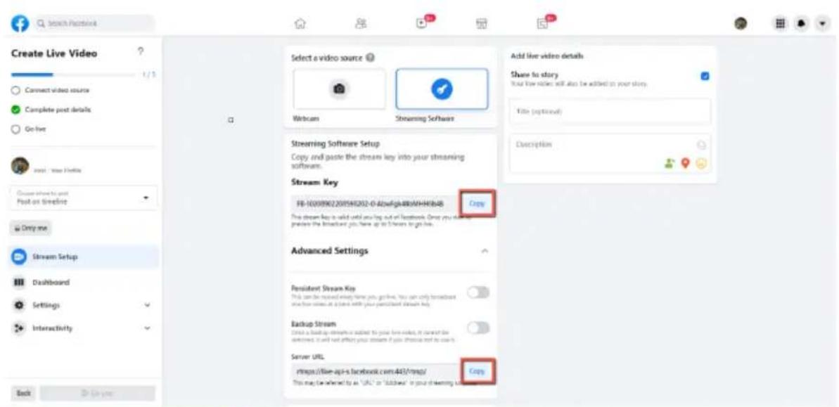
- Please select "Advanced Settings", and then you can see the "Server URL". You need the "Server URL" and the "Stream Key" which are on the page for live-streaming videos on the Facebook page.

- Please click the "Copy" buttons which are located next to the "Server URL" and "Stream Key" columns respectively. After that, please paste them to the "First Stream MRL" column in the "Network" option of the PTC-285T web UI.
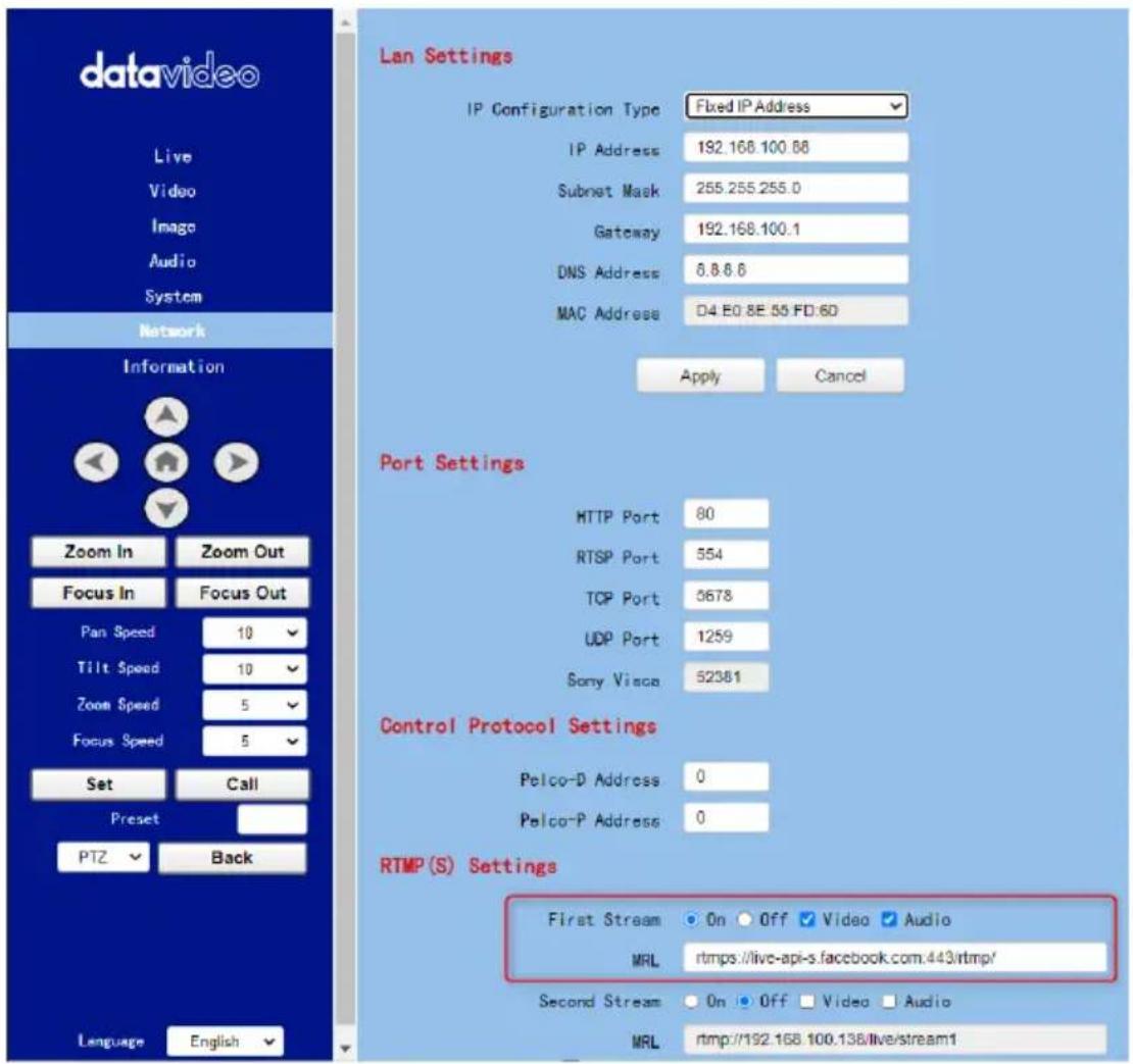
Note: Please make sure that the "ON" is selected for the First Stream MRL. Moreover, please make sure that the "Video" and "Audio" checkboxes are checked.
- Please click the "Apply" button
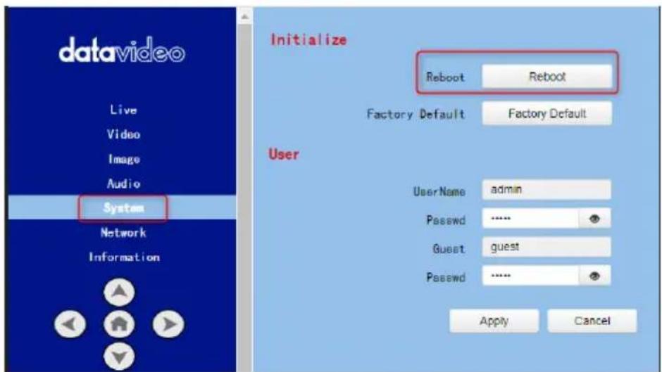
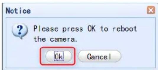
- Please click the "Reboot" button in the "System" option to reboot the PTC-285T.
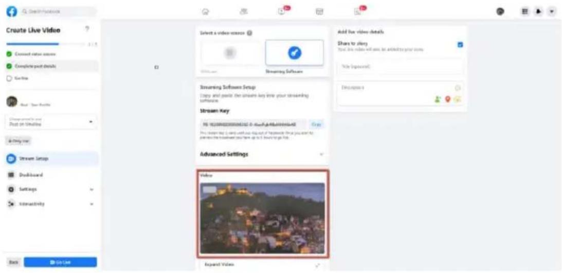
- After the PTC-285T is rebooted, you can see the real-time preview which is shot by the PTC-285T camera from the "Video" option of the Facebook Live page.
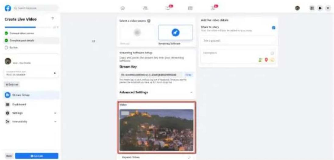
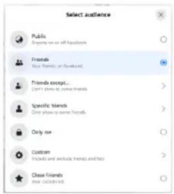
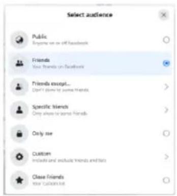
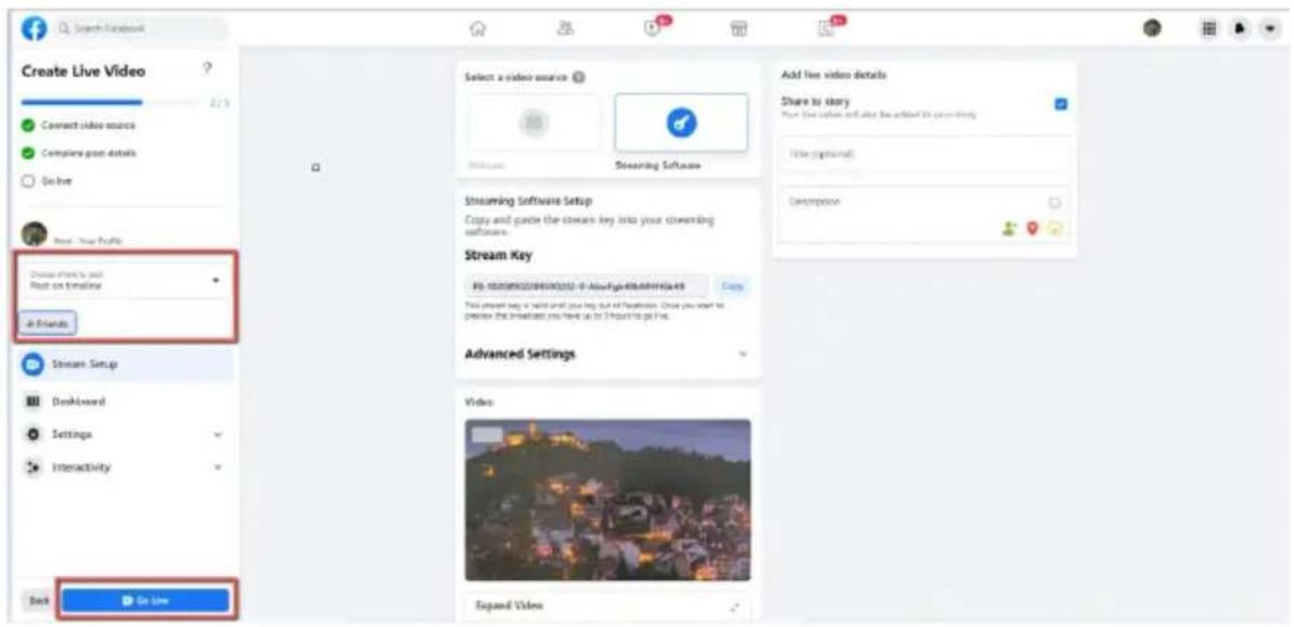
- Please set related settings including "Choose where to post" and "Select audience". After that, please press the "Go Live" button for live-streaming the real-time image which is shot by the PTC-285T immediately.

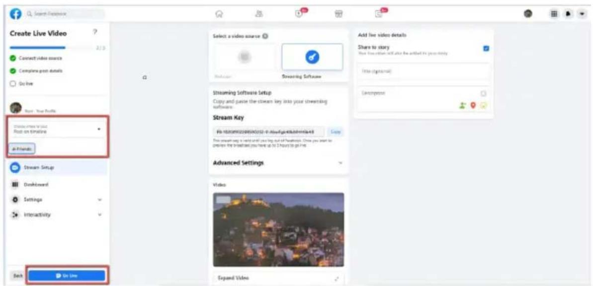
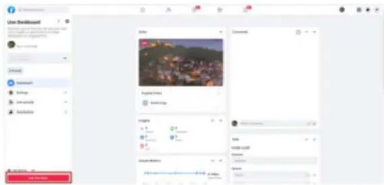
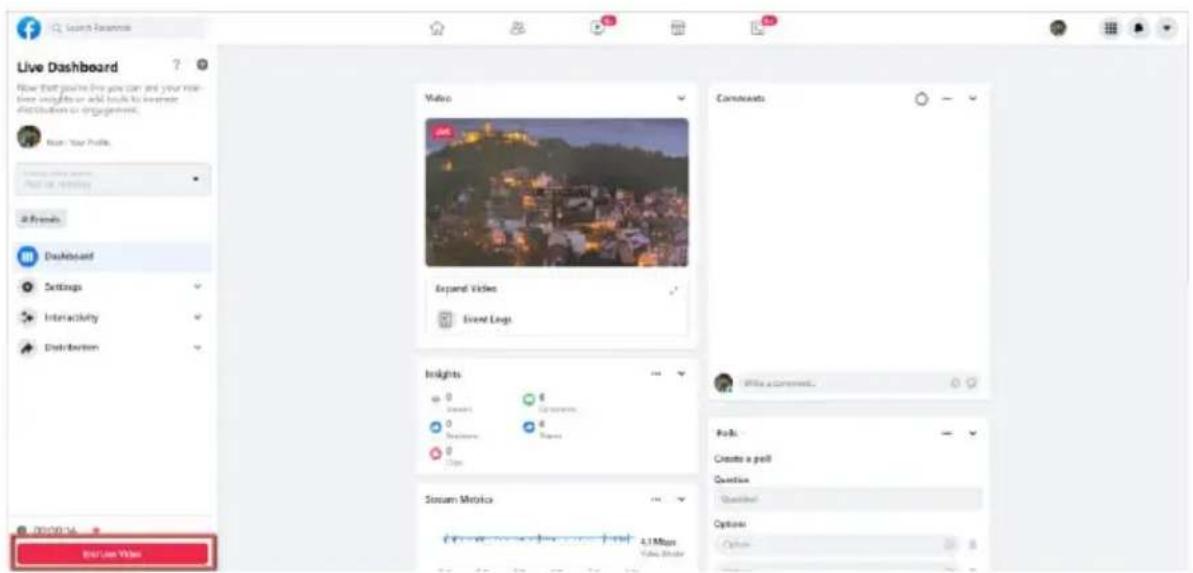
- And then you can see that the live-streaming is done successfully. If you want to stop the live-streaming, please click the "End Live Video" button for stopping the live-streaming immediately.
- Use the Personal Facebook Page or the Facebook Fan Page for Streaming
- Please click the "Select" button from the "Go live" option which is shown in the following diagram.
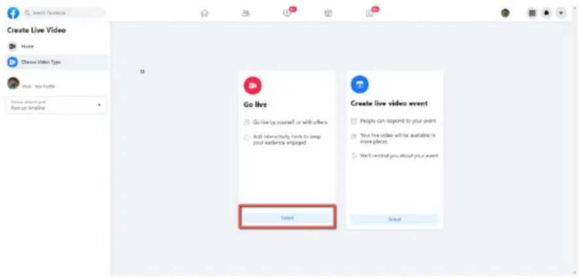
- Please select the "Streaming Software" option, and then please enter the title and description of your live-streaming video in the "Title" and "Description" columns. Moreover, you can determine whether you want to share your live-streaming video to your Facebook Story.
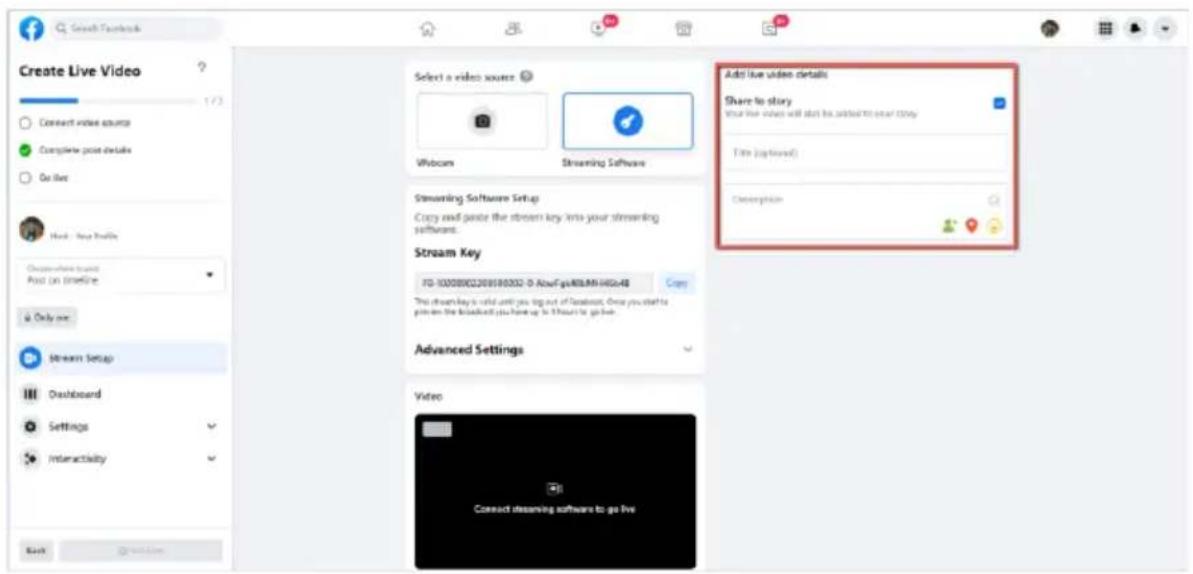
- Please select "Advanced Settings", and then you can see the "Server URL". You need the "Server URL" and the "Stream Key" which are on the page for live-streaming videos on the Facebook page.
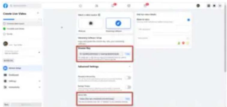
- Please click the "Copy" buttons which are located next to the "Server URL" and "Stream Key" columns respectively. After that, please paste them to the "First Stream MRL" column in the "Network" option of the PTC-285T web UI.
![Create Live Video Current Audio Video Add to other details Show the story Current Audio Video (12.0% or 15.0%) or [16.0% or 18.0%]](/content/2026/05/837136/images/957c941ac21e9a55d0e2c3ff93f19e0385c5258c9612ad83999a3586f48558d3.jpg)
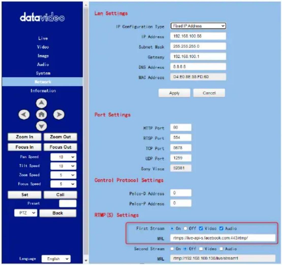
Note: Please make sure that the "ON" is selected for the First Stream MRL. Moreover, please make sure that the "Video" and "Audio" checkboxes are checked.
-
Please click the "Apply" button. Apply
-
Please click the "Reboot" button in the "System" option to reboot the PTC-285T.
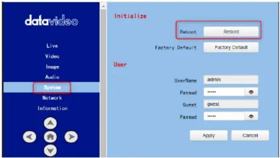
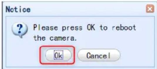
- After the PTC-285T is rebooted, you can see the real-time preview which is shot by the PTC-285T camera from the "Video" option of the Facebook Live page.
- Please set related settings including "Choose where to post" and "Select audience". After that, please press the "Go Live" button for live-streaming the real-time image which is shot by the PTC-285T immediately.

- And then you can see that the live-streaming is done successfully. If you want to stop the live-streaming, please click the "End Live Video" button for stopping the live-streaming immediately.
15. How to Stream to Youtube
Please see following steps for realizing how to stream to Youtube streaming platform.
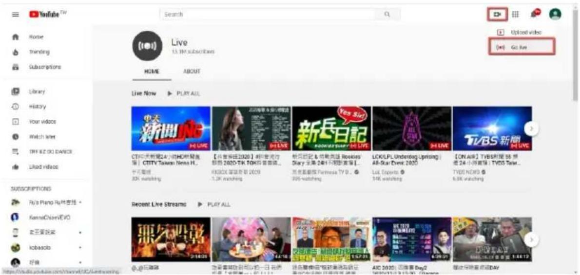
- Please go to Youtube website www.youtube.com and then click "Create->Go Live".
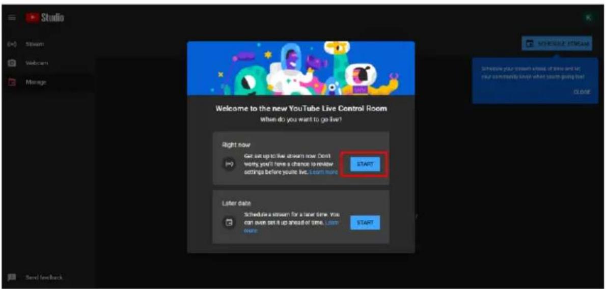
- Users will enter "Youtube Live Control Room" page, please click the "START" button from the "Right Now" option.
- Please click "Go" button from the "Streaming Software" option.
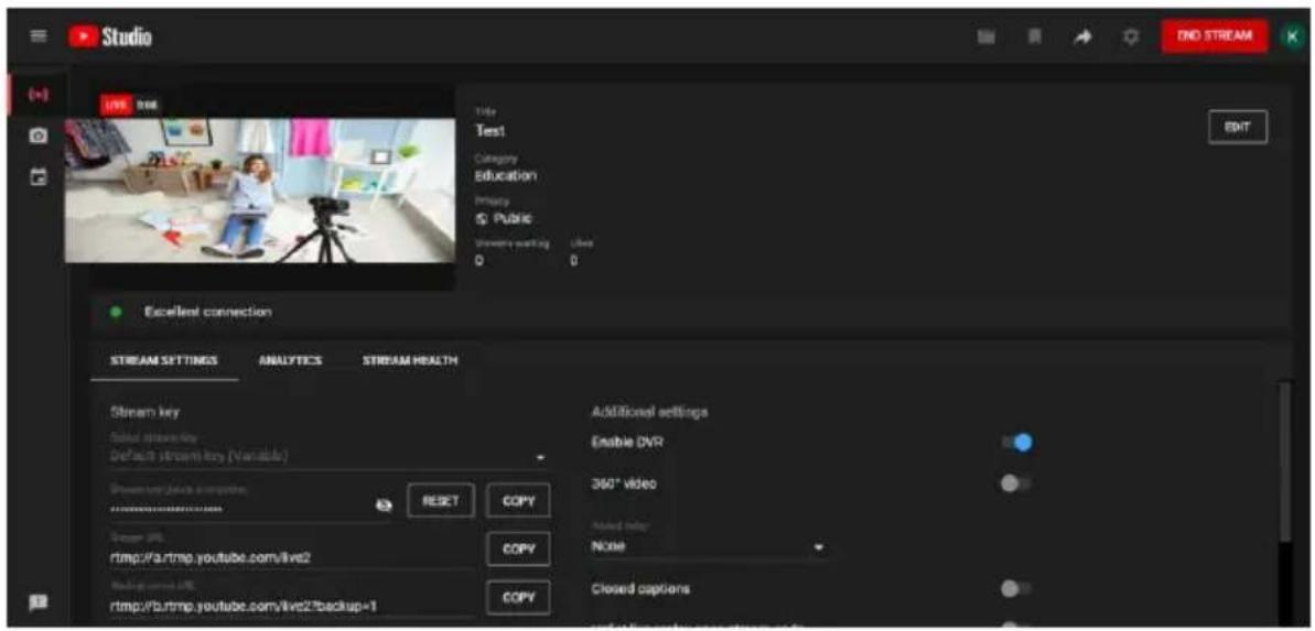
- Users will see the main page of the "Youtube Studio". Please click the "EDIT" button for setting detail information of your streaming activity. After you finish filling out those information, please click the "SAVE" button.
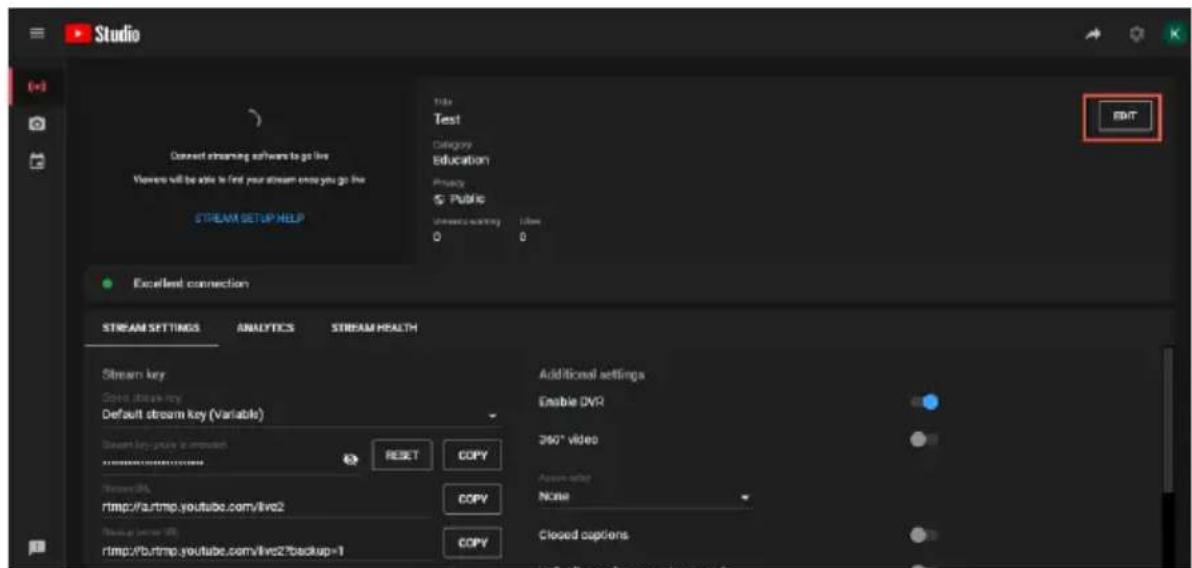
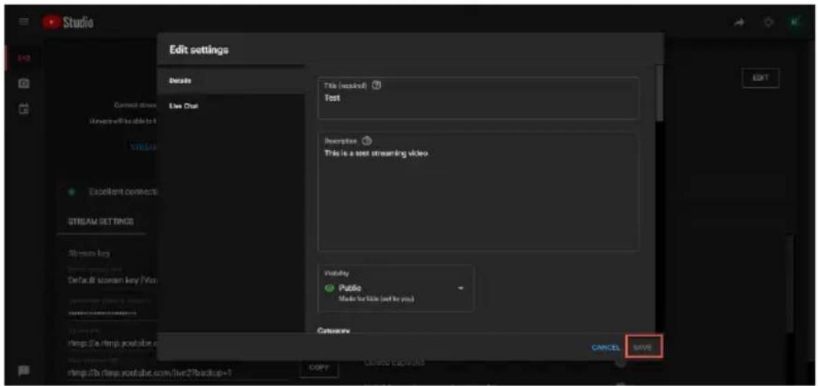
- Users can see the Stream Key and Stream URL that are provided by the Youtube streaming platform. Please copy the stream key and stream URL and then paste them into the "First Stream MRL" within the "Network" option of the PTC-285T Web UI. Please click "On" and please check the checkboxes of "Audio" and "Video".
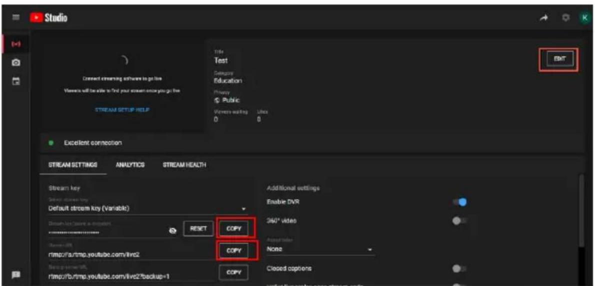
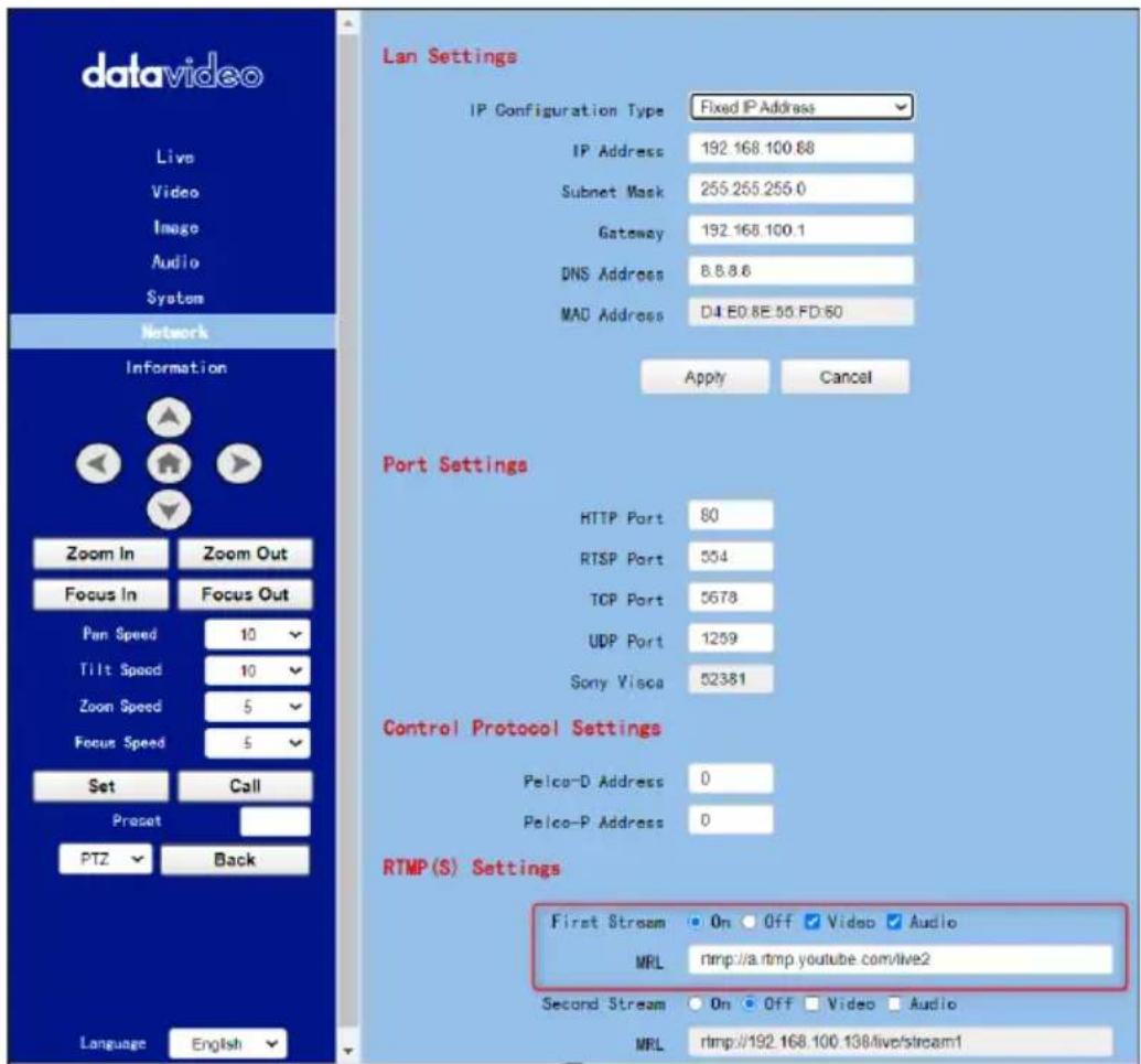
- Please click the "Apply" button.
Apply
- Please reboot the PTC-285T camera and then users can see the streaming is started on the Youtube Live page. If you want to stop the live streaming, please click the "END STREAM" button for stopping the live streaming.
16. How to do the SRT Streaming by the vMix Software
How to install the Vmix Software
Please install the vMix software according to following steps.
- At first, please go to vMix official website and then download the vMix 60-day free-trial. This section will use vMix free-trial as an example to demonstrate the operation steps. Please click the "DOWNLOAD FREE TRIAL"

button for downloading.
- Please double-click the vmix23.exe

vmix23
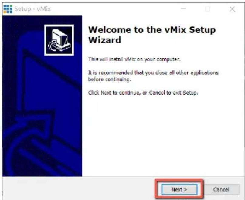
- Please click the "Next" button.
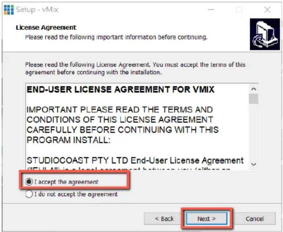
- Please click "I accept the agreement" and then click the "Next" button.
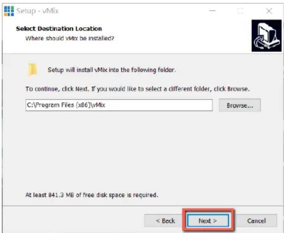
- Please click the "Next" button.
6. Please click the "Next" button.
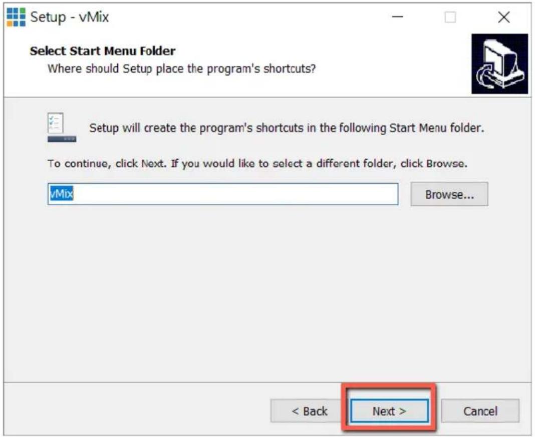
7. Please click the "Next" button.
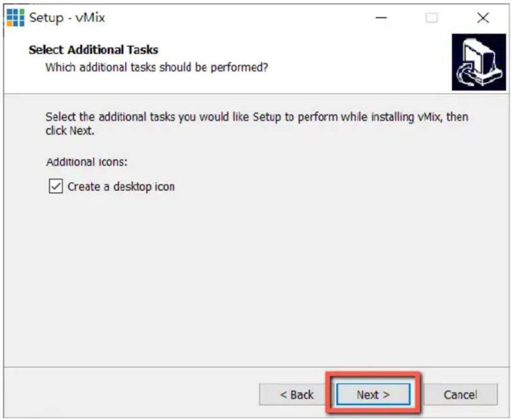
8. Please click the "Install" button.
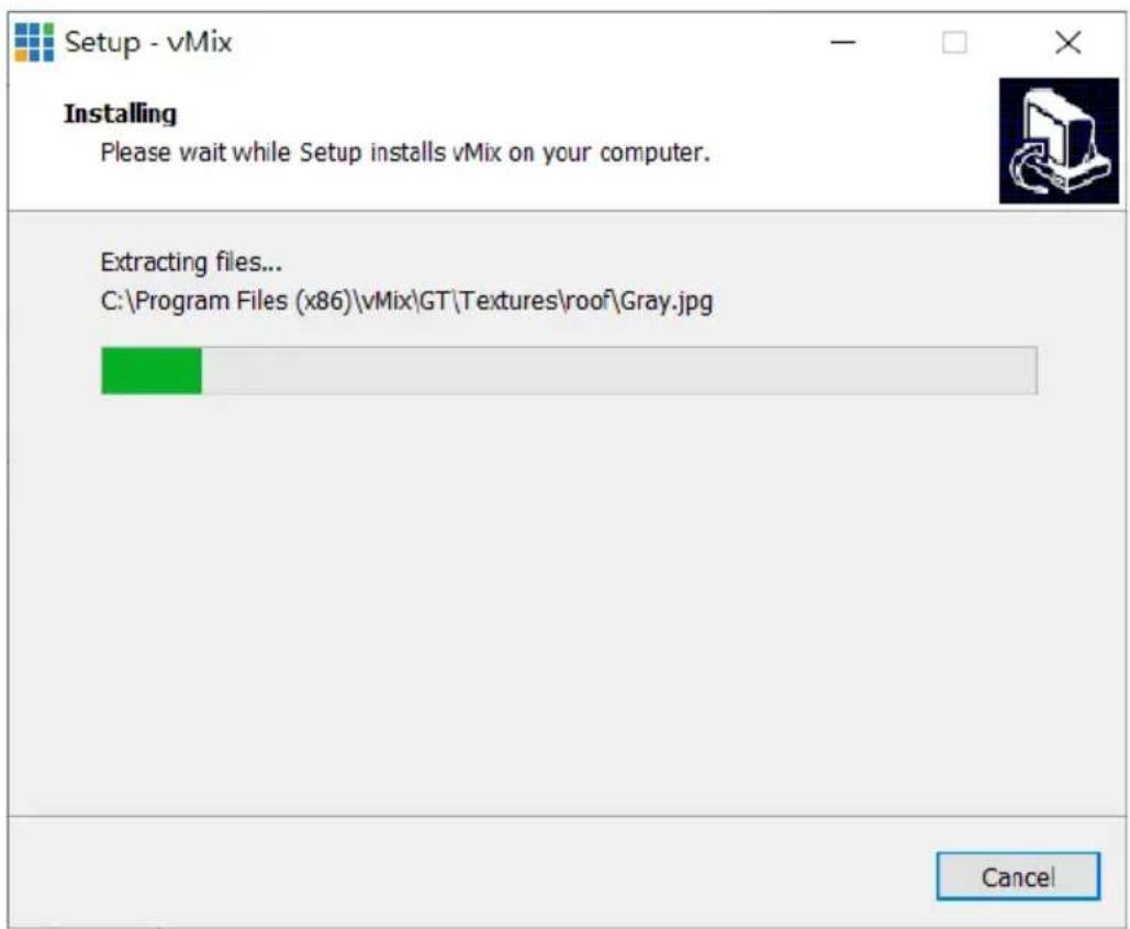
9. The installation will be started.
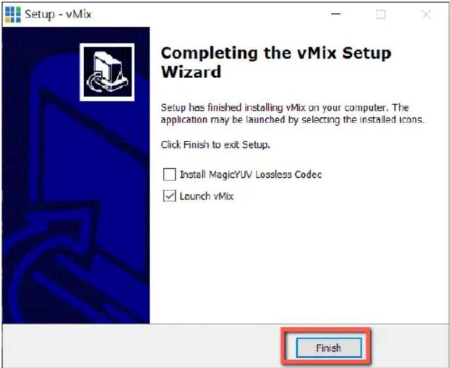
- Please click the "Finish" button to finish the installation.
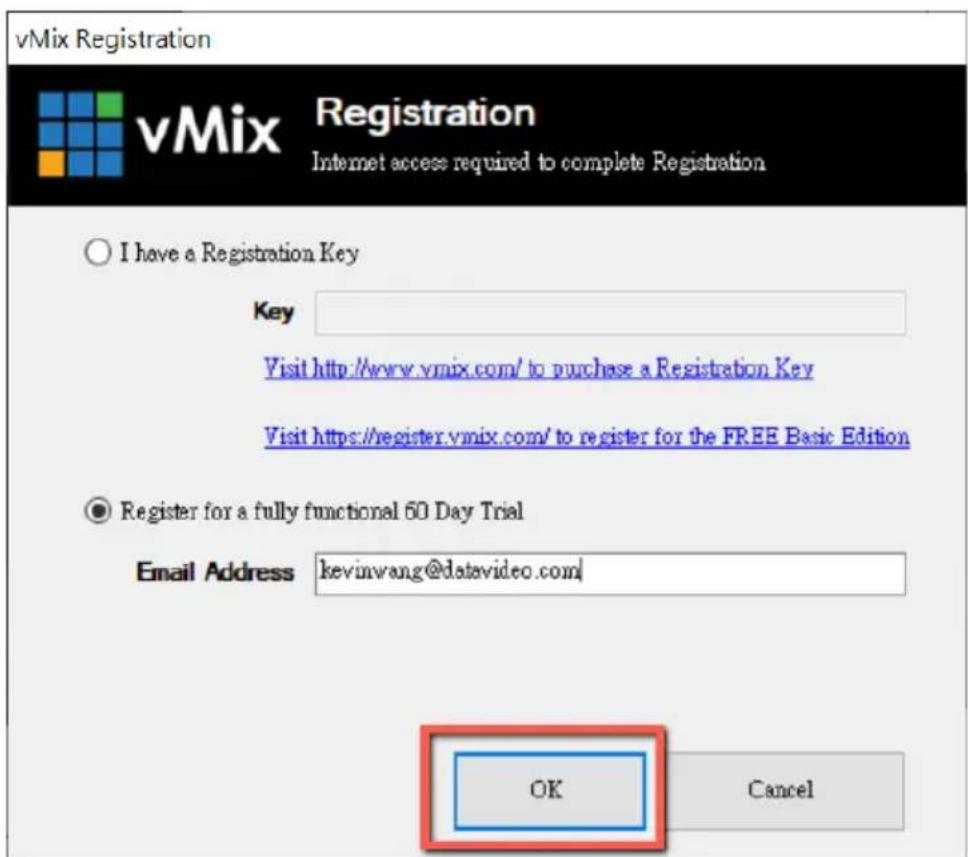
- Please select "Register for a fully functional 60 Day Trial" to fill out your Email Address. After that, please click the "OK" button to open the vMix software.
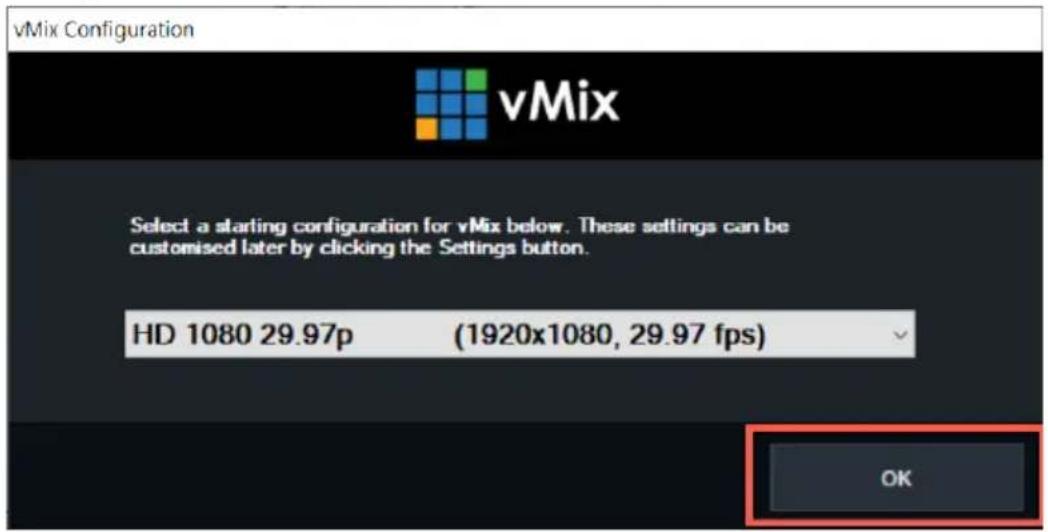
- Please select the initial resolution and frame rate that you want to use and then please click the "OK" button.
- After opening vMix, the software interface is shown as following diagram.
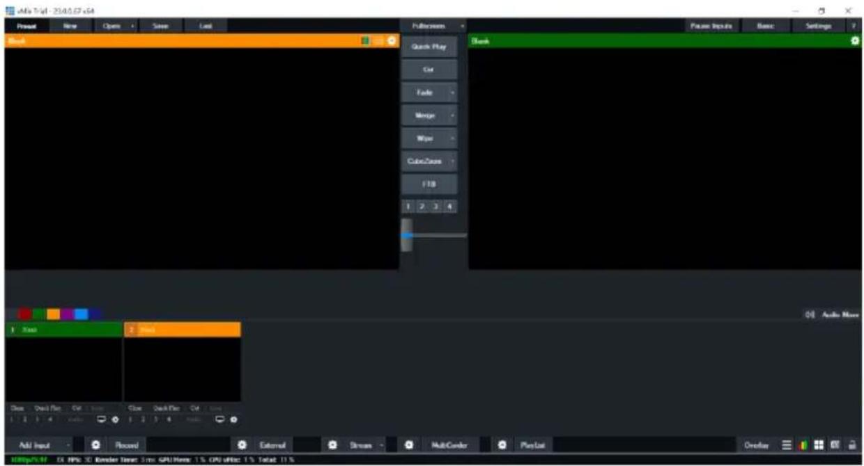
How to do the SRT Stream by Using the PTC-285T Camera and vMix Software
There are two modes for the SRT streaming including the Caller Mode and the Listener Mode. Please see following steps for realizing operation steps for the vMix.
If the PTC-285T is set in Listener Mode
- At first, please click the "Vmix(x64)" from the Start Menu to open the Vmix software.
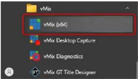
- After that, you will see the Vmix main interface which is shown in the following diagram.
![File 48 - [1.0.0.0] x4 Spread Flow Open Save Last Flash Back Paste Inputs Enter Settings Quick Plan Cut Tools VirtualMan Pipe PTD 1 2 3 4 Block Auto New T Bars 2 Bars Down Quick Play Cut Clear Quick Play Cut 1 2 3 4 Audio Activate Windows Go to Settings for the Home Window Add Input Reward External Stream Mid-Center Playlist Device Action Mode: Action Options: 0% Off, Edit Down, Add Import, Print Copy, Print Sub, Print Active](/content/2026/05/837136/images/340f794adecf20dc413d6aea4fa994a46b1030683b1a75521dc5d527fd1c00ea.jpg)
- Please go back to the PTC-285T interface to make sure that the “SRT” option in the SRT Settings is “ON”. Moreover, the default value of the “SRT Port” is “4578”. The “SRT Encryption” drop-down menu allows you to select your desired SRT Encryption way including AES-128, AES-192 and AES-256. The default value of the “SRT Encryption” option is “Off”. In this section, we will take AES-256 as an example. If you need to set an SRT password, please enter your desired SRT password in the “SRT Password” column, it needs a 10-digit or above number. The default SRT Password is “1234567890”. After the setting for the SRT Password is finished, please press the “Apply” button which is located on the bottom side of the Web UI to apply the new setting.
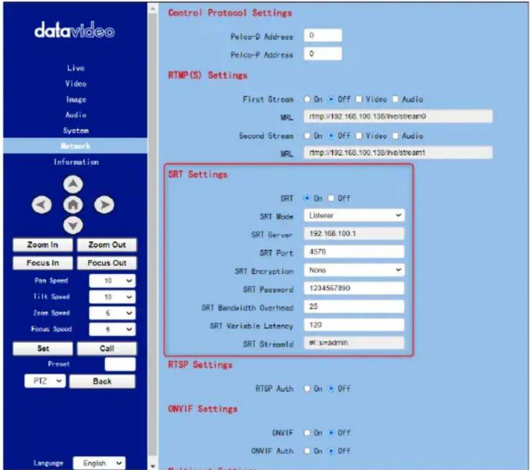
- Please go back to the main interface of the Vmix software and then press the "Add Input" button. After that, please select the "More" option from the drop-up menu.
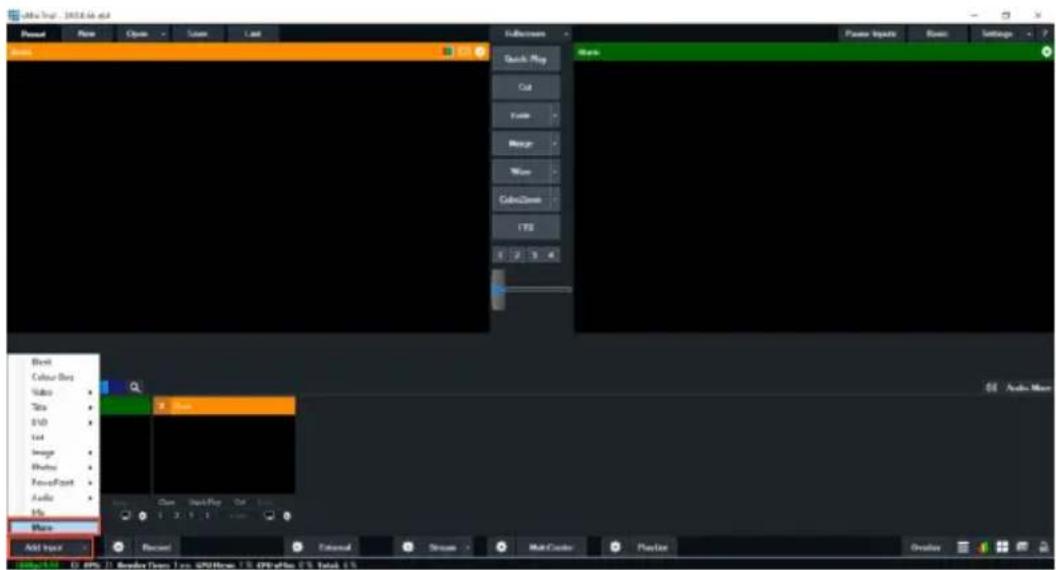
- After the “Input Select” option is opened, please select the “Stream/SRT” option and then you can see the “Stream/SRT” interface which is shown in the following diagram.
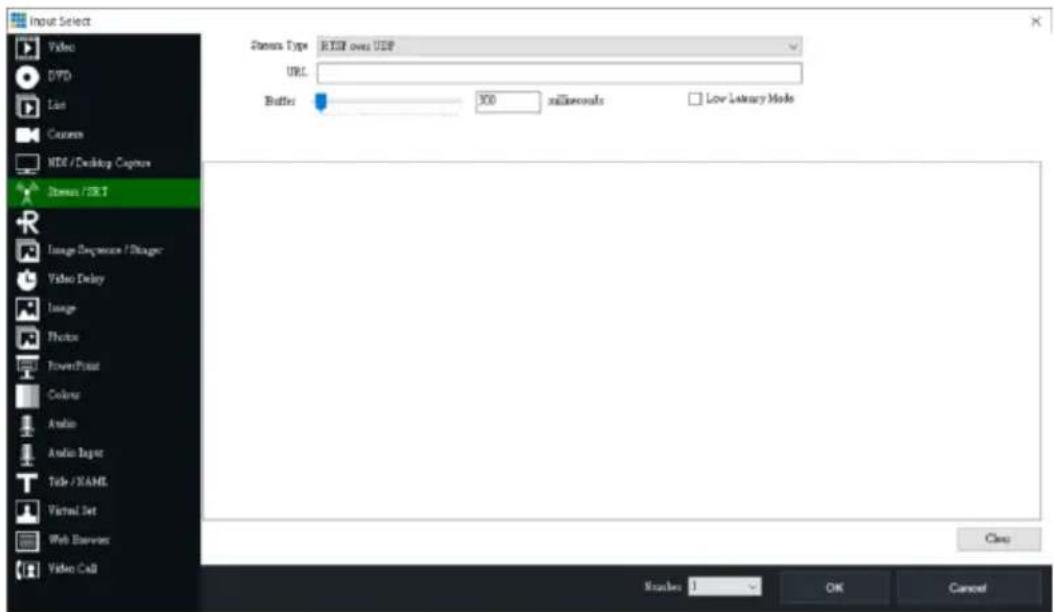
- Please select the “SRT Caller” option from the “Stream Type” drop-down menu. After that, please enter the default static IP address “192.168.100.88” of the PTC-285T into the “Hostname” column. Moreover, please enter the default SRT port number “4578”, which is provided by PTC-285T web UI’s “SRT Port” column into the “Port” column. After that, please enter your SRT Password which is set in the PTC-285T web UI into the “Passphrase” column. The default password is “1234567890”. For the “Key Length”, please select “32” from the drop-down menu. After all of the values are entered, please press the “OK” button.
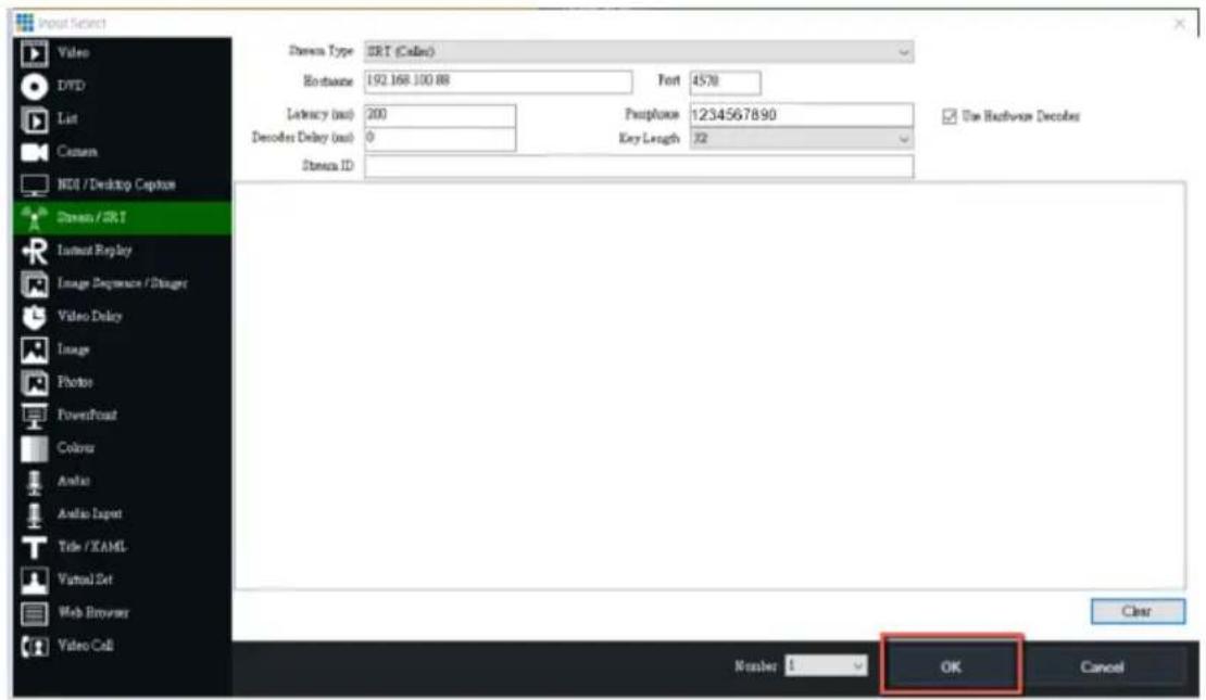
- After that, you can see that the image which is shot by the PTC-285T is streamed to the vMix software by the SRT Listener Mode successfully.
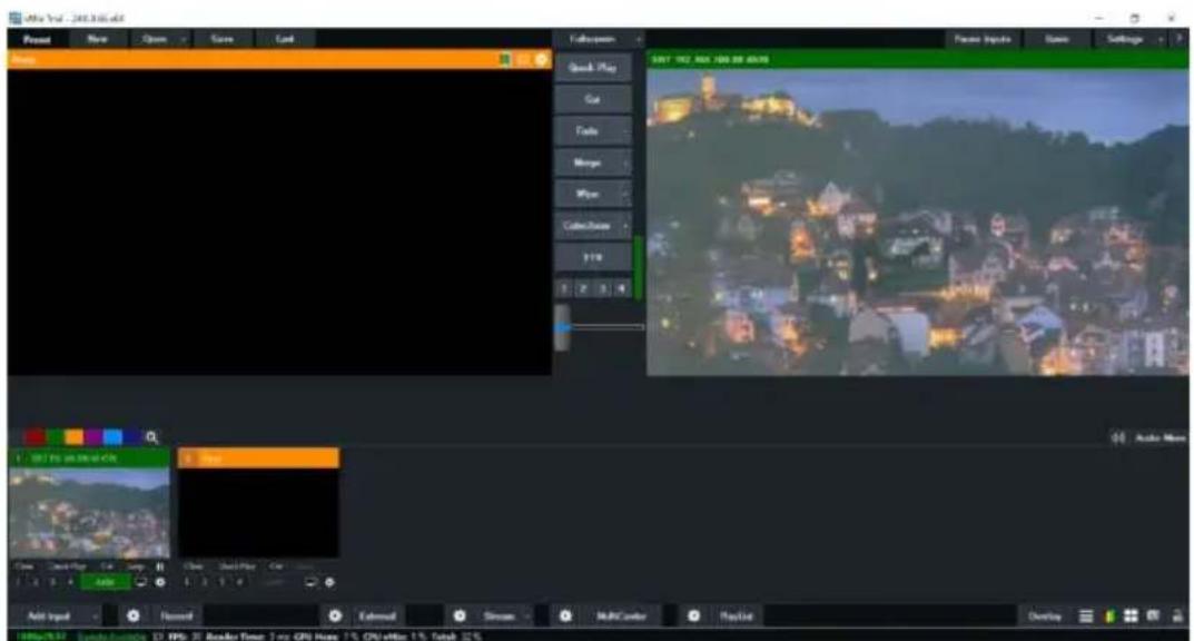
If the PTC-285T is set in Caller Mode
- At first, please click the "Vmix(x64)" from the Start Menu to open the Vmix software.
- After that, you will see the Vmix main interface which is shown in the following diagram.
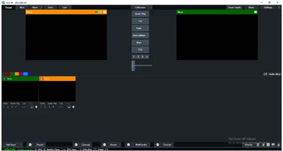
- At first, please go back to the PTC-285T web UI and then please click "ON" from the "SRT" option.
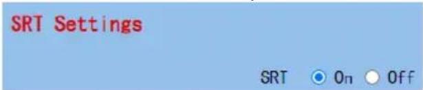
- Please select "Caller" from the "SRT Mode" drop-down menu.
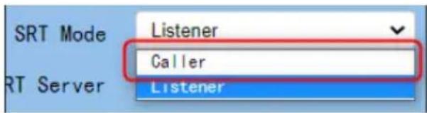
- Please enter the static IP address of your device which is used to install the vmix software. In this example, it is the static IP address "192.168.100.30" of the PC which is used to install the Vmix software. Please pay attention that the static IP address of the device must be within the same LAN as the static IP address of the PTC-285T.
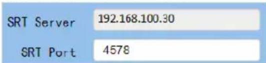
-
The SRT port is "4578", which is the default SRT port number of the PTC-285T.
-
Please select your desired SRT Encryption way from the "SRT Encryption" drop-down menu. In this example, we will take the AES-256 as an example.
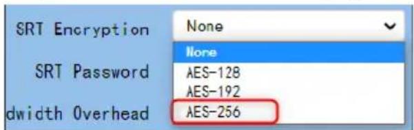
- Please enter your desired SRT password in the "SRT Password" option. Please pay attention that the password must be a 10-digit or above number. In this example, we will take "1234567890" as an example.
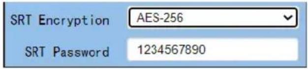
- Please press the "Apply" button.
Apply
- Please press the "Reboot" button from "System-> Reboot" from the PTC-285T web UI.
Reboot
Reboot
- Please go back to the Vmix interface, press the “More” option by pressing the “Add Input” option. After that, please select the “Stream/SRT” option. Please select “SRT Listener” from the “SRT Type” option. After that, please enter the default port number “4578” which is provided by the PTC-285T web UI into the “Port” column. Moreover, please enter your SRT password which is set in the PTC-285T web UI into the “Passphrase” column. In this example, we will take “1234567890” as an example. After that, please select “32” from the “Key Length” drop-down menu. If you have an SRT Stream ID which is provided by your cloud streaming platform, please enter your SRT Stream ID in the “Stream ID” column. After all of them are entered, please press the “OK” button.
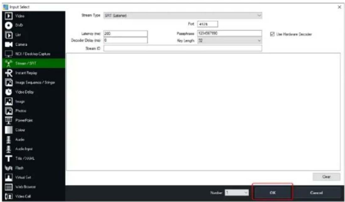
- You can see that the image which is shot by the PTC-285T is shown in the Vmix software by Caller Mode.
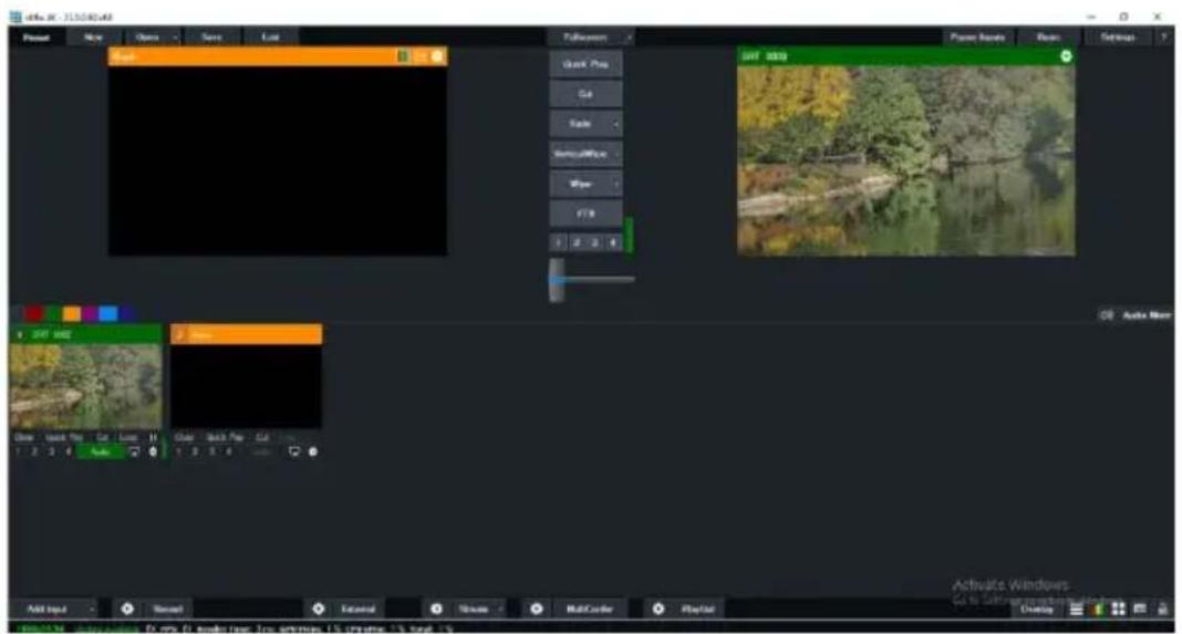
17. Remote Control Port Pinouts
In addition to using the Ethernet port for remote control, you can also connect your PC or any keyboard controllers to the RS-422 remote port to control PTC-285T. Use an Ethernet cable to connect the external RS-422 controller to PTC-285T. You can make your own cable using the pinout information provided in this chapter.
Remote Control Port
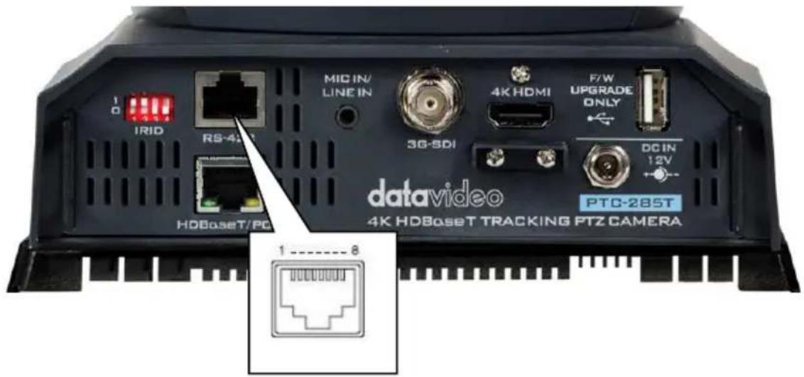
The RS-422 pinouts are described below.
| RMC-180 Controller(RJ-45 Port) | GND | PTC-285T Camera(RS-422 Port) | ||||
| GND | 1 | White/Orange | White/Orange | 1 | GND | |
| NC | 2 | Orange | Orange | 2 | NC | |
| TX- | 3 | White/Green | White/Green | 3 | RX- | |
| RX- | 4 | Blue | Blue | 4 | TX- | |
| RX+ | 5 | White/Blue | White/Blue | 5 | TX+ | |
| TX+ | 6 | Green | Green | 6 | RX+ | |
| NC | 7 | White/Brown | White/Brown | 7 | NC | |
| NC | 8 | Brown | Brown | 8 | NC | |
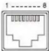 1/EXT 1/EXT | 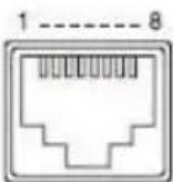 1/EXT 1/EXT | |||||
The RS-232 pinouts are described below.
RS-232
| PTC-285T Camera(RS-232 Port) | ||
| GND | 1 | White/Orange |
| NC | 2 | Orange |
| NC | 3 | White/Green |
| NC | 4 | Blue |
| TX | 5 | White/Blue |
| RX | 6 | Green |
| NC | 7 | White/Brown |
| NC | 8 | Brown |
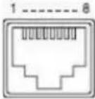 | ||
18. Firmware Update
Datavideo usually releases new firmware containing new features or reported bug fixes from time to time. Customers can either download the firmware as they wish or contact their local dealer or reseller for assistance.
This section outlines the firmware upgrade process which should take approximately few minutes to complete.
The existing settings should persist through the firmware upgrade process, which should not be interrupted once started as this could result in a non-responsive unit.
18.1 Firmware Update by the PTC-285T Firmware Update Tool Requirements
- PTC-285T Unit
- PC/Laptop
- Latest Firmware
- Download from: https://www.datavideo.com/product/PTC-285T
- Ethernet Cable
Procedure
- At first, please confirm that the IP address of your laptop is set within the same LAN as the PTC-285T camera. Please use an Ethernet cable to connect from the RJ-45 Ethernet port of your laptop to the DVIP port which is on the rear panel of the PTC-285T.
- Please download the PTC-285T firmware
"VXxxD_Ax.D_Vx.x.xxx_xx.xM_yyyymmdd" and firmware update tool "upgrade vx.x" from Datavideo official website.
- Please unzip the downloaded firmware and firmware update tool to the hard disk of your laptop.
-
Please double-click the firmwar3e update tool upgrade.exe . ↑ upgrade
-
Users can see that the interface of the firmware update tool is shown as following diagram.
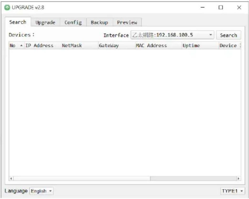
- Please select the LAN IP address which is set by your laptop from the "Interface" drop-down menu.
Interface
乙太網路:192.168.100.5
區域連線* 2:169.254.187.22
區域連線* 4:169.254.183.113
Wi-Fi:192.168.10.113
- Please select the "Upgrade" option and then users can see the interface which is shown as following diagram.
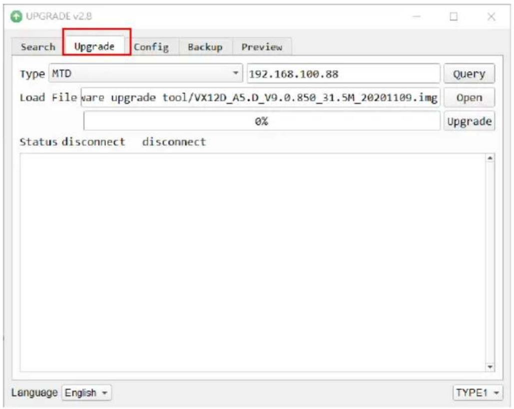
- Please click the "Open" button and select the downloaded latest firmware.
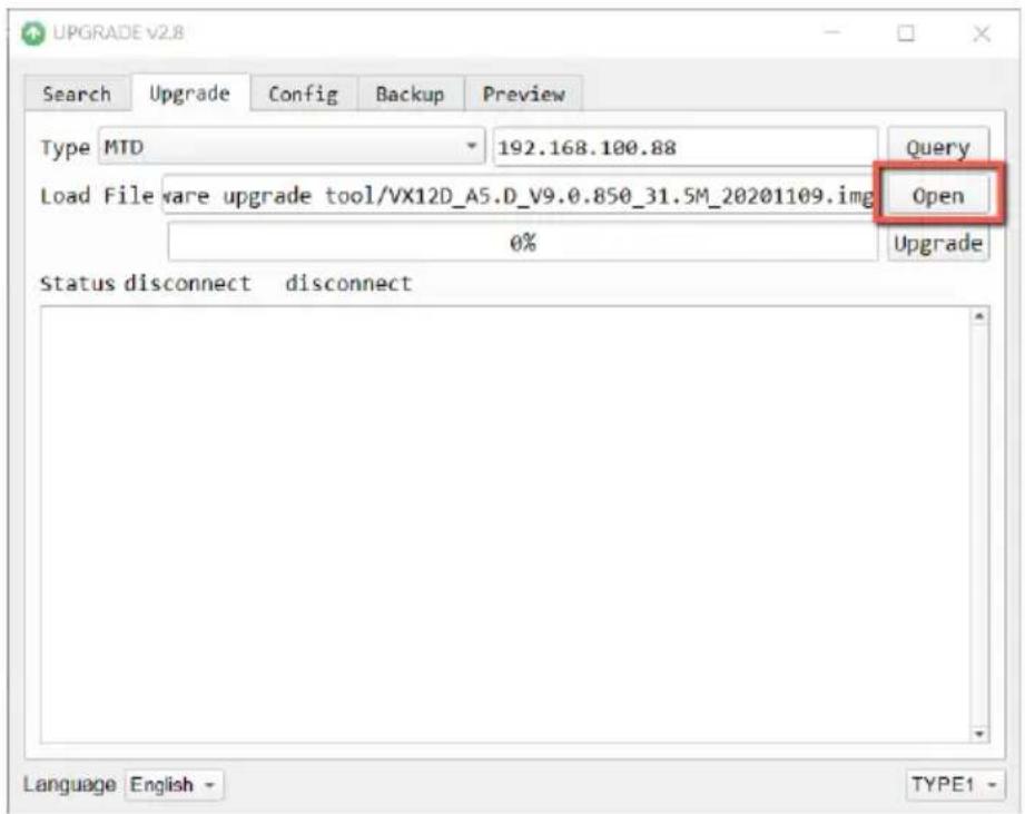
- Please click the "Upgrade" button for starting the firmware upgrading. At this time, the external connected monitor will show the wording "Upgrading! Please Wait!"
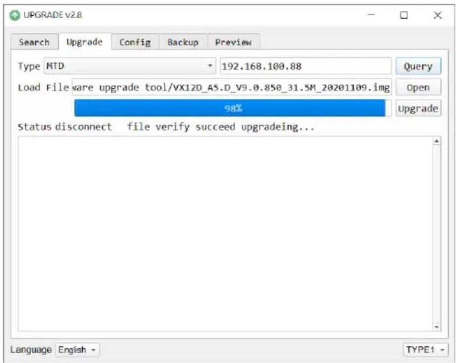
- After the firmware upgrading is finished, the PTC-285T camera will reboot automatically, please click the "OK" button and then the firmware upgrade procedure is completed.
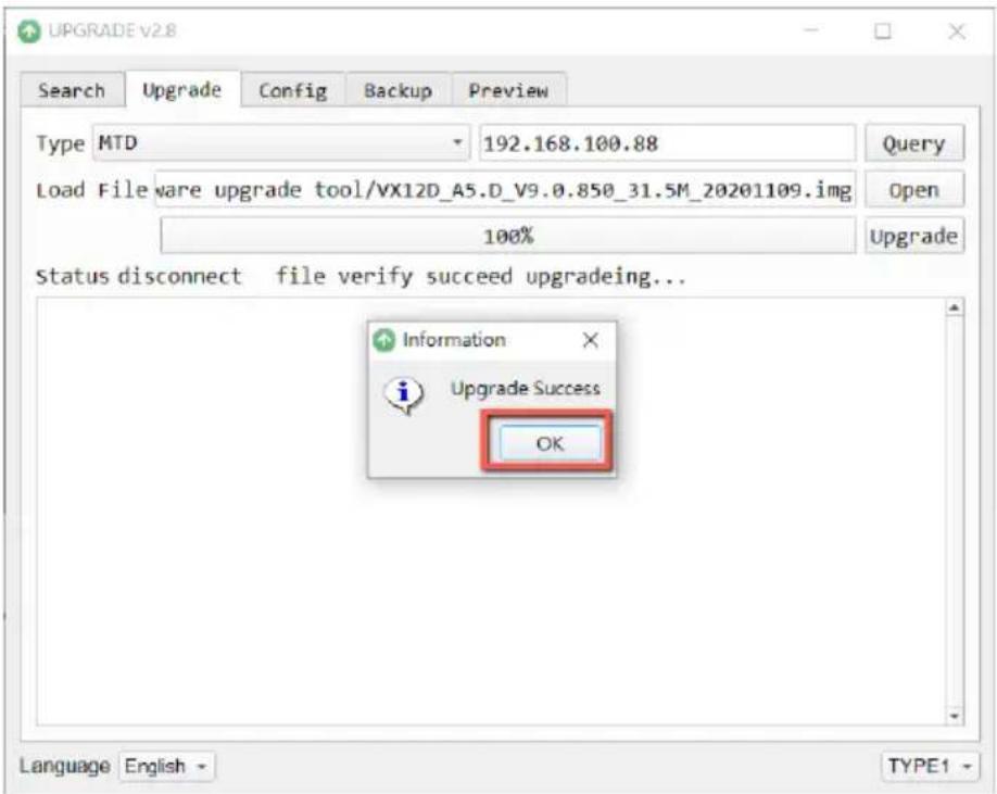
18.2 Firmware Update by the USB Flash Drive Requirements
- PTC-285T Unit
- USB 2.0 or USB3.x USB Flash Drive x 1
- Laptop
- Latest firmware files
- Ethernet Cable
Download from: https://www.datavideo.com/product/PTC-285T
Procedure
- At first, please format your USB flash drive in FAT32 format.
- Please download the latest PTC-285T firmware file from Datavideo official website's PTC-285T product page https://www.datavideo.com/product/PTC-285T and then save it to the hard disk of your laptop.
- Please unzip the downloaded firmware file and then save the latest firmware file "VX12D_A5.D_Vx.x.xxx_31.5M_yyyymmdd.img" into the root directory of your USB flash drive.

VX12D_A5.D_V9.0.897_31.5M_20210312.img
- Please insert your USB flash drive with the latest firmware file into the "F/W UPGRADE ONLY" USB interface which is located on the rear panel of the PTC-285T.

-
Please press the "MENU" button from the PTC-285T remote controller to open the OSD menu.
-
Please move down the PTC-285T remote controller's "Microjoystick"
to the "Setup" option in the OSD menu.
- After the "Setup" option is selected, please press the "Microjoystick"
from the PTC-285T remote controller to enter the "Setup" page.
![MENU Exposure Color Image P/T/Z Noise Reduction Setup Communication Setup Infomation Restore Default [Home] Enter [Menu] Exit](/content/2026/05/837136/images/e7bc40fe4e08d25ce5bb78769520736db64375cbb0caf976e4b5394dd619fcc0.jpg)
- Please move down the "Microjoystick" of the PTC-285T remote controller to the "USB Upgrade" option in the "Setup" page.
![SETUP Language EN HDMI RGB Mode HDMI Video Format 1080P59.94 Audio Select LINE IN SDI-3G Mode LEVEL-A ►USB UPGRADE Off VISCA ID By DIP Audio Channel Stereo ► Select Item ◆ Change Value [Menu] Back](/content/2026/05/837136/images/71f21bbc4021ed6cc22aaa7521d03a34a4987352bd78ad4cc7d2064ed8aa42be.jpg)
- Please move the "Microjoystick" to the left side or right side to set the
of the PTC-285T remote controller
that, please press the “Microjoystick” from the PTC-285T remote controller for confirmation. And then the PTC-285T will start the firmware update procedure automatically. During the process of the firmware update procedure, the reminder “Updating! Please Wait!” will be shown on the screen. When the firmware update procedure is done, the PTC-285T will reboot automatically and the firmware update is done successfully.
Note: Please do not turn off your computer during the firmware update process to prevent it from crashing. Moreover, there is a period of time that there is no image that will be shown on the monitor. At this moment, please do not turn off the power of the PTC-285T camera. The camera will reboot automatically after the whole firmware update procedure is done.
![SETUP Language EN HDMI RGB Mode HDMI Video Format 1080P59.94 Audio Select LINE IN SDI-3G Mode LEVEL-A ►USB UPGRADE On VISCA ID By DIP Audio Channel Stereo ▲▼ Select Item ◆▼ Change Value [Menu] Back [Home] OK Upgrading! Please Wait!](/content/2026/05/837136/images/11b8fc99eff233083211b51cb80c30a60c1cd2d44a294a10ba086e4edbd6591f.jpg)
19. Frequently-Asked Questions
This section describes problems that you may encounter while using PTC-285T. If you have any questions, please refer to related sections and follow all suggested solutions. If problem still exists, please contact your distributor or the service center.
| No. | Problems | Solutions |
| 1. | What are important points for product maintenance? | 1. If the camera will not be used for a long time, please unplug the 12V DC power plug, and remove AC power adapter from AC outlet.2. Use soft cloth or tissue to clean the camera.3. After washing the camera lens, dry it with a soft dry cloth. Use a neutral detergent rather than acidic or corrosive detergents to clean the lens. |
| 2. | There is no output video. | 1. Check that your power is properly connected. This is indicated by the power LED.2. After you reboot the camera, please check that whether the camera can do the self-test normally or not.3. Please check that the camera is connected correctly to the external connected monitor. |
| 3. | I have seen image jitter while zooming in or out. | 1. Make sure the camera is properly mounted.2. Make sure that machines that could cause vibration are not in proximity of the camera. |
| 4. | There is no image by using the IE browser. | Please go the the VLC website (http://www.videolan.org/vlc) to download the 32-bit VLC media player. After it is installed, the screen will be shown normally when connecting to the camera. |
| 5. | The camera can not be accessed by using the IE browser. | 1. Use PC to access the internet to see whether it can operate normally or not. At first, please solve the network failure that is caused by the computer virus until the PC and the camera can ping each other.2. Please remove the Ethernet cable and then connect the PC to the camera directly. After that, please reset the IP address of the PC. |
| 6. | The remote control is not working. | 1. Try setting the camera to CAM1 and try again.2. Make sure the remote control's battery is fully charged.3. Check your device working mode.4. Make sure the OSD menu is closed. The remote control cannot be used if the OSD menu is opened. |
| 7. | The serial port is not working properly. | 1. Make sure your baud rate and device addresses are correct.2. Check your device working mode.3. Make sure the OSD menu is closed. The remote control cannot be used if the OSD menu is opened. |
| 8. | Can not login to the Web control interface. | 1. Please check your Ethernet cable.2. Please check your Ethernet setting such as the IP address. |
20. Dimensions
| Unit: mm | ||
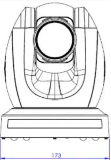 | 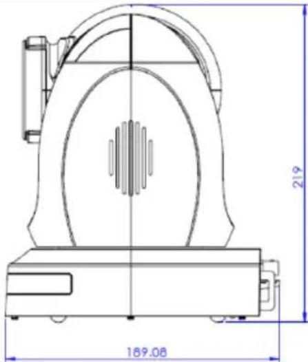 | |
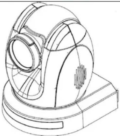 | 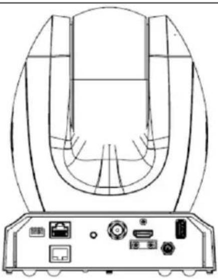 | |
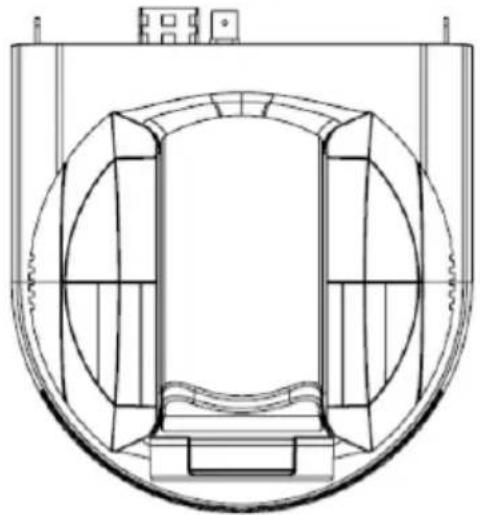 | ||
- Specifications
| Camera Parameters | |
| Product Name | 4K HDBaseT Tracking PTZ Camera |
| Video Format | 2160p60/59.94/50/30/29.97/251080p60/59.94/50/30/29.97/251080i60/59.94/50720p60/59.94/50*2160p60/59.94/50 YUV 4:2:2 |
| Image Sensor | 1/2.8" CMOS |
| Effective Pixels (approx.) | 8.51Mega Pixels |
| S/N Ratio | ≥55dB |
| Min. Illumination | 0.5 Lux @ (F1.8, AGC ON) |
| Electronic Shutter | 1/30s ~ 1/10000s |
| Zoom Ratio | 12x Optical Zoom, 16x Digital Zoom |
| Gamma | Off / Normal |
| Iris Control | Auto / Manual |
| Digital Noise Reductions | 3D |
| On-Screen Display (OSD) | English/Simplified Chinese/Traditional Chinese |
| White Balance | Auto, Indoor, Outdoor, OnePush, Manual, VAR |
| AGC / Gain Control | Yes |
| Mirror / Flip Image | Yes |
| Focus Mode | Auto / Manual |
| Panning / Tilting Range | Pan: 300 degrees,Tilt: +130 to -15 degrees |
| Panning / Tilting Speed | Pan: 0.876°/s~43°/sTilt: 0.693°/s ~21.32°/s |
| Preset | 255 Position |
| Focal Length | 12x, f=4.4 to 52.8 mmF1.8 to F2.6 |
| Field of View (Horizontal, Wide) | 80° |
| Image Compensation | Back light compensation |
| Input /Output Interfaces | |
| Video Output | HDMI 2.0 x13G-SDI x1HDBaseT x 110/100/1000M RJ45 (PoE) x1 |
| Audio Input | 3.5 mm x1 (mic in/line in)switch from Web UI |
| Tally LED | Yes |
| Lens Filter | N/A |
| Control Protocol | Pelco-D, Pelco-P,VISCA, VISCA over IP, DVIP |
| Remote Control Interface | IRWeb UIRS-422DVIP |
| Video Compression Format | H.264/H.265/MJPEG |
| Audio Compression Format | AAC |
| Audio Bitrate | 96Kbps, 128Kbps |
| Streaming Protocols | TCP/IP, HTTP, RTSP, RTMP(S), ONVIF, DHCP, Multicast |
| First Stream Supported Resolution | 3840x21601920x10801280x7201024x576960x540640x480640x360 |
| Second Stream Supported Resolution | 720x480640x360480x270320x240 |
| Video Bitrate | 32Kbps ~ 50Mbps (Single Stream) |
| Video Bitrate Mode | VBR, CBR |
| Encoding Frame rate | 50Hz: 1-50fps60Hz: 1-60fps |
| POE | IEEE 802.3at |
| F/W Update | Via Web UI or USB 2.0 |
| IR Control | Yes |
| Camera Control Unit | HS-1600T series/RMC-180 series/RMC-300 series/PTZView Assist APP |
| Tripod Mount | 1/4-20 UNC |
| Optional Accessories | WM-1/ WM-10/ WM-11 |
| Color | Dark Blue/White |
| Dimension (LxWxH) | 173 (W) x 219 (H) x 189.08 (D) mm |
| Weight | 2.6kg |
| Operating Temp.Range | 0~40 °C |
| Power | DC 12V 22W |
Note
Service & Support
It is our goal to make your products ownership a satisfying experience. Our supporting staff is available to assist you in setting up and operating your system. Please refer to our web site www.datavideo.com for answers to common questions, support requests or contact your local office below.
www.datavideo.com/product/PTC-285T
3.
datavideo
www.datavideo.com

@DatavideoUSA @DatavideoIndia2016
@DatavideoEMEA @Datavideojapan
@DatavideoTaiwan @DatavideoLatam
@DatavideoAsia @DatavideoBrasil

@Datavideo
@Datavideo_EMEA
@Datavideo Taiwan

@DatavideoUSA
@DVTWDVCN

@DatavideoUSA
@DatavideoEurope
All the trademarks are the properties of their respective owners.
Datavideo Technologies Co., Ltd. All rights reserved 2020
- Table of Contents
- TABLE OF CONTENTS 2
- FCC COMPLIANCE STATEMENT .... 5
- WARNINGS AND PRECAUTIONS 5
- WARRANTY 7
- DISPOSAL 8
- PRODUCT OVERVIEW....9
- LOCATION AND FUNCTION OF PARTS 10
- BASIC SETUP 14
- REMOTE CONTROL AND ON-SCREEN MENU.... 17
- INSTRUCTION FOR INSTALLATION.... 33
- NETWORK CONNECTION 39
- HOW TO USE PTC-285T'S AI AUTO TRACKING 46
- How to Connect the PTC-285T to a Datavideo Switcher after a 60FPS/50FPS Video Streaming (Take the HS-1300 as an example)....57
- Disclaimer of Product and Services
- FCC Compliance Statement
- Warnings and Precautions
- Warranty
- Standard Warranty
- Three Year Warranty
- Disposal
- For EU Customers only - WEEE Marking
- Product Overview
- Features
- Location and Function of Parts
- Bottom of Camera
- Basic Setup
- Power-On Initialization
- Video Output
- - Connect the PTC-285T camera directly to your PC/Notebook PC
- Note: The default static IP address of the PTC-285T is 192.168.100.88.
- - Connect the PTC-285T camera to your PC or laptop by a router.
- HDMI Video OUT
- 3G-SDI Video Output
- Remote Control and On-Screen Menu
- Remote Control Functions
- OSD Menu
- Professional Jargon Explanations of the OSD
- Menu
- Instruction for installation
- Step 1 – DIP Switch Setting
- Step 2 – One End of Retaining Wire
- Step 3 – Ceiling Bracket (B)
- Step 4 – Ceiling Bracket (A) and Camera
- Step 6 – Screw to Fix Camera
- Step 7 – Cable Connection
- Network Connection
- datavideo
- DHCP Mode
- Static IP
- DVIP
- How to Use PTC-285T's AI Auto Tracking
- How to turn on the AI Auto-Tracking Function
- How to turn off the AI Auto-Tracking Function
- Single-Person Scene Auto-Tracking Mode
- Multi-Person Scene Auto-Tracking Mode
- Web User Interface
- Live
- Video
- How to Connect the PTC-285T to a Datavideo Switcher after a 60FPS/50FPS Video Streaming (Take the HS-1300 as an example)
- ● Take the adjustment to 1080i59.94 as an example
- Image
- Audio
- System
- Network
- Information
- The PTZ Control Area of the Web UI
- How to Use the Web UI to Set and Call Presets
- ● How to Set Preset
- ● How to Recall Preset
- Control the Camera by the PTZ View Assist App
- DIP Switch Settings
- DIP Switch SW1
- DIP Switch SW2 (IRID)
- How to Play the RTSP Stream by the VLC Player
- Please click "Play" button.
- How to Play the Multicast by the VCL Player
- How to Stream to Facebook
- ● Use Facebook Live Producer for Streaming
- Please go to Facebook Live website
- How to Stream to Youtube
- Apply
- How to do the SRT Streaming by the vMix Software
- How to install the Vmix Software
- Please click the "Next" button.
- Please click the "Next" button.
- Please click the "Install" button.
- The installation will be started.
- How to do the SRT Stream by Using the PTC-285T Camera and vMix Software
- If the PTC-285T is set in Listener Mode
- If the PTC-285T is set in Caller Mode
- Remote Control Port Pinouts
- Firmware Update
- Firmware Update by the PTC-285T Firmware Update Tool Requirements
- Procedure
- Interface
- 乙太網路:192.168.100.5
- Firmware Update by the USB Flash Drive Requirements
- Frequently-Asked Questions
- Dimensions
- Note
- Service & Support
Brand : DataVideo
Model : PTC-285T
Category : Security Camera