
27052 - Lawn mower Craftsman - Free user manual and instructions
Find the device manual for free 27052 Craftsman in PDF.


| Product Type | Lawn Mower |
| Brand | Craftsman |
| Model | 27052 |
| Engine Type | Gasoline, 4-Stroke |
| Engine Displacement | 140 cc |
| Cutting Deck Width | 21 inches |
| Cutting Height Settings | 6 positions, 1 to 3.5 inches |
| Grass Collection | Rear bag, capacity 2.5 bushels |
| Mulching Capability | Yes, with included plug |
| Drive Type | Push (manual) |
| Weight | 75 lbs (34 kg) |
| Wheel Size | Front: 8 inches, Rear: 10 inches |
| Fuel Capacity | 0.5 gallons |
| Oil Capacity | 20 oz (0.6 L) |
| Start Type | Recoil |
| Safety Features | Blade brake, operator presence control |
| Maintenance | Change oil every 25 hours, air filter annually |
| Warranty | 2 years limited |
Frequently Asked Questions - 27052 Craftsman
User questions about 27052 Craftsman
0 question about this device. Answer the ones you know or ask your own.
Ask a new question about this device
Download the instructions for your Lawn mower in PDF format for free! Find your manual 27052 - Craftsman and take your electronic device back in hand. On this page are published all the documents necessary for the use of your device. 27052 by Craftsman.
USER MANUAL 27052 Craftsman
WITH SMART LAWN TECHNOLOGY


Model Nos. 247.27050*, 247.27052* & 247.27054*
*-- Last digit of model number varies
Safe Operation Practices ....2
Slope Gauge ....6
Assembly 7
Smart Lawn Activation....10
Operation....11
Service and Maintenance 21
Off-Season Storage 32
Troubleshooting 33
Español....35
Warranty/Service......See Separate Supplement
NOTE: This Operator's Manual covers several models. Features may vary by model. Not all features in this manual are applicable to all models and the model depicted may differ from yours.

This product has a low emission engine which operates differently from previously built engines. Before you start the engine, read and understand this Craftsman Operator's Manual and the Engine Operator's Manual.
CAUTION
Before using this equipment, read this manual and follow all safety rules and operating instructions.
To order parts or schedule service for this product, call:
1-888-331-4569
Craftsman Customer Hot Line
Sears Brands Management Corporation, Hoffman Estates, IL 60179 U.S.A.
Used under license Visit our website: www.craftsman.com

Form No. 769-11240D
(November 27, 2017)
SAFETY INSTRUCTIONS
WARNING
This symbol points out important safety instructions which, if not followed, could endanger the personal safety and/or property of yourself and others. Read and follow all instructions in this manual before attempting to operate this machine. Failure to comply with these instructions may result in personal injury. When you see this symbol, HEED ITS WARNING!
WARNING
CALIFORNIA PROPOSITION 65
Engine Exhaust, some of its constituents, and certain vehicle components contain or emit chemicals known to State of California to cause cancer and birth defects or other reproductive harm. Battery posts, terminals, and related accessories contain lead and lead compounds, chemicals known to the State of California to cause cancer and reproductive harm. Wash hands after handling.
! DANGER
This machine was built to be operated according to the safe operation practices in this manual. As with any type of power equipment, carelessness or error on the part of the operator can result in serious injury. This machine is capable of amputating fingers, hands, toes and feet and throwing debris. Failure to observe the following safety instructions could result in serious injury or death.
WARNING
Your Responsibility—Restrict the use of this power machine to persons who read, understand and follow the warnings and instructions in this manual and on the machine.
SAVE THESE INSTRUCTIONS!
GENERAL OPERATION
- Read, understand, and follow all instructions on the machine and in the manual(s) before attempting to assemble and operate. Keep this manual in a safe place for future and regular reference and for ordering replacement parts.
- Be familiar with all controls and their proper operation. Know how to stop the machine and disengage them quickly.
- Never allow children under 14 years of age to operate this machine. Children 14 and over should read and understand the instructions and safe operation practices in this manual and on the machine and should be trained and supervised by an adult.
- Never allow adults to operate this machine without proper instruction.
- To help avoid blade contact or a thrown object injury, keep bystanders, helpers, children and pets at least 75 feet from the machine while it is in operation. Stop machine if anyone enters the area.
- Thoroughly inspect the area where the equipment is to be used. Remove all stones, sticks, wire, bones, toys, and other foreign objects which could be picked up and thrown by the blade(s). Thrown objects can cause serious personal injury.
- Plan your mowing pattern to avoid discharge of material toward roads, sidewalks, bystanders and the like. Also, avoid discharging material against a wall or obstruction which may cause discharged material to ricochet back toward the operator.
• Always wear safety glasses or safety goggles during operation and while performing an adjustment or repair to protect your eyes. Thrown objects which ricochet can cause serious injury to the eyes. - Wear sturdy, rough-soled work shoes and close-fitting slacks and shirts. Loose fitting clothes and jewelry can be caught in movable parts. Never operate this machine in bare feet or sandals.
- Be aware of the mower and attachment discharge direction and do not point it at anyone. Do not operate the mower without the discharge cover or entire grass catcher in its proper place.
-
Do not put hands or feet near rotating parts or under the cutting deck. Contact with the blade(s) can amputate hands and feet.
-
A missing or damaged discharge cover can cause blade contact or thrown object injuries.
- Stop the blade(s) when crossing gravel drives, walks, or roads and while not cutting grass.
- Watch for traffic when operating near or crossing roadways. This machine is not intended for use on any public roadway.
- Do not operate the machine while under the influence of alcohol or drugs.
- Mow only in daylight or good artificial light.
- Never carry passengers.
- Back up slowly. Always look down and behind before and while backing to avoid a back-over accident. Be aware and pay attention to the safety system function that stops power to the blades when driving in reverse. If not functioning properly, contact an authorized dealer for safety system inspection and repair.
- Slow down before turning. Operate the machine smoothly. Avoid erratic operation and excessive speed.
- Disengage blade(s), set parking brake, stop engine and wait until the blade(s) come to a complete stop before removing grass catcher, emptying grass, unclogging chute, removing any grass or debris, or making any adjustments.
- Never leave a running machine unattended. Always turn off blade(s), place drive control levers in neutral, set parking brake, stop engine and remove key before dismounting.
- Use extra care when loading or unloading the machine into a trailer or truck. This machine should not be driven up or down ramp(s), because the machine could tip over, causing serious personal injury. The machine must be pushed manually on ramp(s) to load or unload properly.
- Muffler and engine become hot and can cause a burn. Do not touch.
- Check overhead clearances carefully before driving under low hanging tree branches, wires, door openings etc., where the operator may be struck or pulled from the machine, which could result in serious injury.
- Disengage all attachment clutches, set the parking brake to the 'on' position and move the RH and LH drive control levers to the neutral position before attempting to start the engine.
SAFETY INSTRUCTIONS
- Your machine is designed to cut normal residential grass of a height no more than 10^ . Do not attempt to mow through unusually tall, dry grass (e.g., pasture) or piles of dry leaves. Dry grass or leaves may contact the engine exhaust and/or build up on the mower deck presenting a potential fire hazard.
- Use only accessories and attachments approved for this machine by the machine manufacturer. Read, understand and follow all instructions provided with the approved accessory or attachment. For a list of approved accessories and attachments, call 1-888-331-4569.
- Data indicates that operators, age 60 years and above, are involved in a large percentage of riding mower-related injuries. These operators should evaluate their ability to operate the riding mower safely enough to protect themselves and others from serious injury.
- If situations occur which are not covered in this manual, use care and good judgment.
SLOPE OPERATION
Slopes are a major factor related to loss of control and tip-over accidents which can result in severe injury or death. All slopes require extra caution. If you cannot back up the slope or if you feel uneasy on it, do not mow it.
For your safety, use the slope gauge included as part of this manual to measure slopes before operating this machine on a sloped or hilly area. If the slope is greater than 15 degrees as shown on the slope gauge, do not operate this machine on that area or serious injury could result.
Do:
- Mow across slopes, not up and down. Exercise extreme caution when changing direction on slopes.
- Watch for holes, ruts, bumps, rocks, or other hidden objects. Uneven terrain could overturn the machine. Tall grass can hide obstacles.
- Use slow speed. Choose a low enough speed so that you will not have to stop while on the slope. Avoid starting or stopping on a slope. If the tires are unable to maintain traction, disengage the blades and proceed slowly and carefully straight down the slope.
- Follow the manufacturer's recommendations for wheel weights or counterweights to improve stability.
- Use extra care with grass catchers or other attachments. These can change the stability of the machine.
- Keep all movement on the slopes slow and gradual. Do not make sudden changes in speed or direction. Rapid acceleration or deceleration could cause the front of the machine to lift and rapidly roll over backwards, which could cause serious injury.
Do Not:
- Do not turn on slopes unless necessary; then turn slowly uphill and use extra care while turning.
- Do not mow near drop-offs, ditches or embankments. The mower could suddenly turn over if a wheel is over the edge of a cliff, ditch, or if an edge caves in.
- Do not try to stabilize the machine by putting your foot on the ground.
- Do not use a grass catcher on steep slopes.
- Do not mow on wet grass. Reduced traction could cause sliding.
- Do not tow heavy pull behind attachments (e.g. loaded dump cart, lawn roller, etc.) on slopes greater than 5 degrees. When going down hill, the extra weight tends to push the riding mower and may cause you to loose control (e.g. riding mower may speed up, braking and steering ability are reduced, attachment may jack-knife and cause riding mower to overturn).
CHILDREN
Tragic accidents can occur if the operator is not alert to the presence of children. Children are often attracted to the machine and the mowing activity. They do not understand the dangers. Never assume that children will remain where you last saw them.
- Keep children out of the mowing area and in watchful care of a responsible adult other than the operator.
- Be alert and turn machine off if a child enters the area.
- To avoid back-over accidents, always look behind and down for small children.
- Never carry children, even with the blade(s) shut off. They may fall off and be seriously injured or interfere with safe machine operation.
- Use extreme care when approaching blind corners, doorways, shrubs, trees or other objects that may block your vision of a child who may run into the path of the machine.
- Keep children away from hot or running engines. They can suffer burns from a hot muffler.
- Remove key when machine is unattended to prevent unauthorized operation.
Never allow children under 14 years of age to operate this machine. Children 14 and over should read and understand the instructions and safe operation practices in this manual and on the machine and should be trained and supervised by an adult.
TOWING
- Tow only with a machine that has a hitch designed for towing. Do not attach towed equipment except at the hitch point.
- Follow the manufacturers recommendation for weight limits for towed equipment and towing on slopes.
- Never allow children or others in or on towed equipment.
- On slopes, the weight of the towed equipment may cause loss of traction and loss of control.
- Travel slowly and allow extra distance to stop.
- Do not shift to neutral and coast downhill.
- Do not tow heavy pull behind attachments (e.g. loaded dump cart, lawn roller, etc.) on slopes greater than 5 degrees. When going down hill, the extra weight tends to push the riding mower and may cause you to loose control (e.g. riding mower may speed up, braking and steering ability are reduced, attachment may jack-knife and cause riding mower to overturn).
SERVICE
Safe Handling of Gasoline:
To avoid personal injury or property damage use extreme care in handling gasoline. Gasoline is extremely flammable and the vapors are explosive. Serious personal injury can occur when gasoline is spilled on yourself or your clothes which can ignite. Wash your skin and change clothes immediately.
- Use only an approved gasoline container.
- Never fill containers inside a vehicle or on a truck or trailer bed with a plastic liner. Always place containers on the ground away from your vehicle before filling.
- When practical, remove gas-powered equipment from the truck or trailer and refuel it on the ground. If this is not possible, then refuel such equipment on a trailer with a portable container, rather than from a gasoline dispenser nozzle.
SAFETY INSTRUCTIONS
- Keep the nozzle in contact with the rim of the fuel tank or container opening at all times until fueling is complete. Do not use a nozzle lock-open device.
- Extinguish all cigarettes, cigars, pipes and other sources of ignition.
- Never fuel machine indoors.
- Never remove gas cap or add fuel while the engine is hot or running. Allow engine to cool at least two minutes before refueling.
- Never over fill fuel tank. Fill tank to no more than 12 inch below bottom of filler neck to allow space for fuel expansion.
- Replace gasoline cap and tighten securely.
- If gasoline is spilled, wipe it off the engine and equipment. Move machine to another area. Wait 5 minutes before starting the engine.
- To reduce fire hazards, keep machine free of grass, leaves, or other debris build-up. Clean up oil or fuel spillage and remove any fuel soaked debris.
- Never store the machine or fuel container inside where there is an open flame, spark or pilot light as on a water heater, space heater, furnace, clothes dryer or other gas appliances.
- Allow a machine to cool at least five minutes before storing.
General Service
- Never run an engine indoors or in a poorly ventilated area. Engine exhaust contains carbon monoxide, an odorless, and deadly gas.
- Before cleaning, repairing, or inspecting, make certain the blade(s) and all moving parts have stopped. Disconnect the spark plug wire and ground against the engine to prevent unintended starting.
- Periodically check to make sure the blades come to complete stop within approximately (5) five seconds after operating the blade disengagement control. If the blades do not stop within the this time frame, have your machine serviced professionally by Sears or another qualified dealer.
- Regularly check the safety interlock system for proper function, as described later in this manual. If the safety interlock system does not function properly, have your machine serviced professionally by Sears or another qualified dealer.
- Check the blade(s) and engine mounting bolts at frequent intervals for proper tightness. Also, visually inspect blade(s) for damage (e.g., excessive wear, bent, cracked). Replace the blade(s) with the original equipment manufacturer's (O.E.M.) blade(s) only, listed in this manual. Use of parts which do not meet the original equipment specifications may lead to improper performance and compromise safety!
- Mower blades are sharp. Wrap the blade or wear gloves, and use extra caution when servicing them.
- Keep all nuts, bolts, and screws tight to be sure the equipment is in safe working condition.
- Never tamper with the safety interlock system or other safety devices. Check their proper operation regularly.
- After striking a foreign object, stop the engine, disconnect the spark plug wire(s) and ground against the engine. Thoroughly inspect the machine for any damage. Repair the damage before starting and operating.
-
Never attempt to make adjustments or repairs to the machine while the engine is running.
-
Grass catcher components and the discharge cover are subject to wear and damage which could expose moving parts or allow objects to be thrown. For safety protection, frequently check components and replace immediately with original equipment manufacturer's (O.E.M.) parts only, listed in this manual. Use of parts which do not meet the original equipment specifications may lead to improper performance and compromise safety!
- Do not change the engine governor settings or over-speed the engine. The governor controls the maximum safe operating speed of the engine.
- Maintain or replace safety and instruction labels, as necessary.
- Observe proper disposal laws and regulations for gas, oil, etc. to protect the environment.
- According to the Consumer Products Safety Commission (CPSC) and the U.S. Environmental Protection Agency (EPA), this product has an Average Useful Life of seven (7) years, or 270 hours of operation. At the end of the Average Useful Life have the machine inspected annually by Sears or another qualified dealer to ensure that all mechanical and safety systems are working properly and not worn excessively. Failure to do so can result in accidents, injuries or death.
DO NOT MODIFY ENGINE
To avoid serious injury or death, do not modify engine in any way. Tampering with the governor setting can lead to a runaway engine and cause it to operate at unsafe speeds. Never tamper with factory setting of engine governor.
NOTICE REGARDING EMISSIONS
Engines which are certified to comply with California and federal EPA emission regulations for SORE (Small Off Road Equipment) are certified to operate on regular unleaded gasoline, and may include the following emission control systems: Engine Modification (EM), Oxidizing Catalyst (OC), Secondary Air Injection (SAI) and Three Way Catalyst (TWC) if so equipped.
SPARK ARRESTOR
WARNING
This machine is equipped with an internal combustion engine and should not be used on or near any unimproved forest-covered, brush-covered or grass-covered land unless the engine's exhaust system is equipped with a spark arrestor meeting applicable local or state laws (if any).
If a spark arrestor is used, it should be maintained in effective working order by the operator. In the State of California the above is required by law (Section 4442 of the California Public Resources Code). Other states may have similar laws. Federal laws apply on federal lands.
A spark arrestor for the muffler is available through your nearest Sears Parts and Repair Service Center.
SAFETY INSTRUCTIONS
SAFETY SYMBOLS
This page depicts and describes safety symbols that may appear on this product. Read, understand, and follow all instructions on the machine before attempting to assemble and operate.
| SymbolDescription | |
 | READ THE OPERATOR'S MANUAL(S)Read, understand, and follow all instructions in the manual(s) before attempting to assemble and operate |
 | DANGER — ROTATING BLADESNever carry passengers. Never carry children, even with the blades off. |
 | DANGER — ROTATING BLADESMowing in reverse is not recommended. |
 | WARNING — ROTATING BLADESDo not put hands or feet near rotating parts or under the cutting deck. Contact with the blade(s) can amputate hands and feet. |
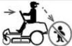 | DANGER — ROTATING BLADESLook down and behind before and while backing to avoid a back-over accident. |
 | WARNING — THROWN OBJECTSThis machine may pick up and throw and objects which can cause serious personal injury. |
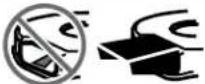 | DANGER — SAFETY DEVICESKeep safety devices (guards, shields, switches, etc.) in place and working. |
 | WARNING — BYSTANDERSKeep bystanders, helpers, children and pets at least 75 feet from the machine while it is in operation. |
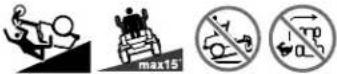 | WARNING — SLOPE OPERATIONDo not operate this machine on a slope greater than 15 degrees. Do not mow up and downslopes. Mow across slopes no greater than 15 degrees. Avoid sudden turns. Use low speed. If machine stops going uphill, stop blades and back down slowly. |
 | WARNING — HOT SURFACEEngine parts, especially the muffler, become extremely hot during operation. Allow engine and muffler to cool before touching. |
 | DANGER — ROTATING BLADESTo reduce the risk of injury, keep hands and feet away. Do not operate unless discharge cover or grass catcher is in its proper place. If damaged, replace immediately. |
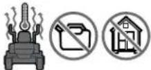 | WARNING — FIRE HAZARDAIow machine to cool before fueling or storing. |
 | WARNING — FIRE HAZARDDo not drive through piles of dry leaves or tall grass. |
 | WARNING — FIRE HAZARDOperation of this equipment may create sparks that can start fires around dry vegetation. A spark arrestor may be required. |
SLOPE GAUGE
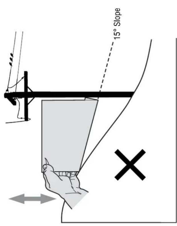
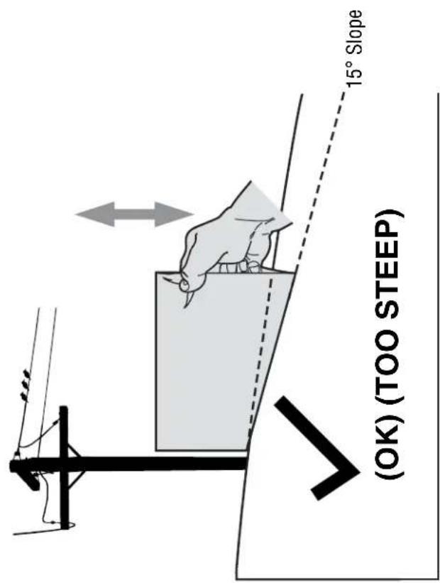
Figure 2Figure 1
To check the slope, proceed as follows:
1. Remove this page and fold along the dashed line.
2. Locate a vertical object on or behind the slope (e.g. a pole, building, fence, tree, etc.)
3. Align either side of the slope gauge with the object (See Figure 1 and Figure 2).
4. Adjust gauge up or down until the left corner touches the slope (See Figure 1 and Figure 2).
5. If there is a gap below the gauge, the slope is too steep for safe operation (See Figure 2 above).
15°
dashed line
USE THIS SLOPE GAUGE TO DETERMINE
IF A SLOPE IS TOO STEEP FOR SAFE OPERATION!
WARNING
Slopes are a major factor related to tip-over and roll-over accidents which can result in severe injury or death. Do not operate machine on slopes in excess of 15 degrees. All slopes require extra caution. If you cannot back up the slope or if you feel uneasy on it, do not mow it. Always mow across the face of slopes, never mow up and down the face of slopes.
ASSEMBLY
Set-Up
NOTE: Remove the deck wash system nozzle adapter from the manual bag and store for future use.
Moving The Riding Mower Manually
Your riding mower's transmission is equipped with a hydrostatic relief valve for occasions when it is necessary to move the riding mower manually. Opening this valve permits the fluid in the transmission to bypass its normal route, allowing the rear tires to "freewheel." To open the hydrostatic relief valve, proceed as follows:
- Locate the hydrostatic bypass rod in the rear of the riding mower. See Figure 1.
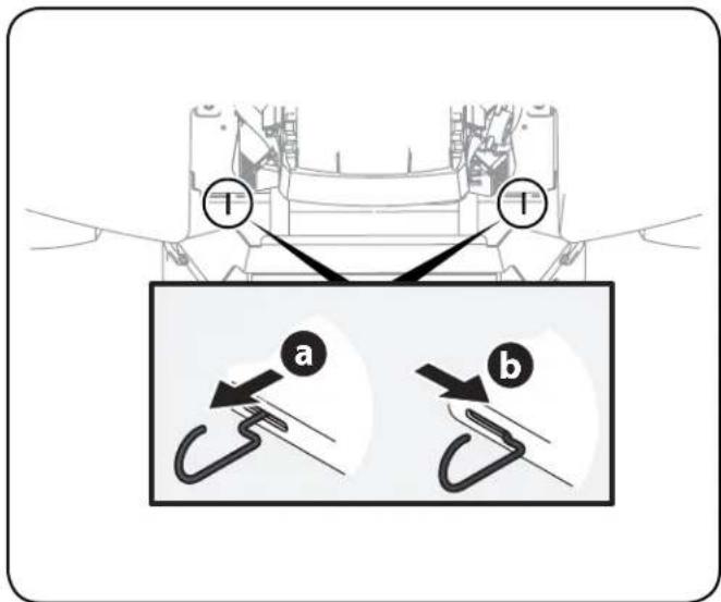
Figure 1
- Engage the bypass rods by pulling each one out (a) and to the right (b) to lock it into place. See Figure 1.
- Disengage the bypass rods by reversing steps a & b after moving the tractor. See Figure 1.
NOTE: The transmission will NOT engage when the hydrostatic bypass rod is pulled out. Return the rod to its normal position prior to operating the riding mower.

CAUTION
Never attempt to move the riding mower manually without first opening the hydrostatic relief valve. Doing so will result in serious damage to the riding mower's transmission.
Install Operator's Seat
To install the seat proceed as follows:
NOTE: The seat is shipped with the seat switch and seat pan attached.
- Cut any straps securing the seat assembly and the drive control levers to the riding mower. Remove any packing material.
NOTE: Be careful not to cut the wiring harness connecting the seat and the seat switch. - Remove the two shoulder bolts and lock nuts in the seat pan as shown in Figure 2.
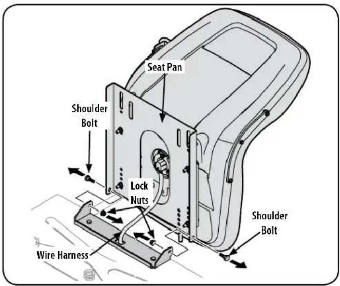
Figure 2
- Rotate the seat into position and secure the seat into place with the previously removed shoulder bolts and lock nuts. Be careful not to crimp or damage the wire harness while installing the seat. See Figure 3.

Figure 3
ASSEMBLY
Position Drive Control levers
The drive control levers of the riding mower are lowered for shipping purposes. The flange lock nuts, hex screws, and flat washers that normally secure the control levers in their operating position are unfastened and installed in the slotted holes of the control levers for shipment. The control levers must be repositioned to operate the riding mower. To reposition the control levers for operation, proceed as follows:
- Remove the hex screws and flat washers from the hardware pack in your manual bag.
- Lift and swing that control lever upward until the slotted hole in the lever bracket aligns with one of the holes in the pivot bracket. See Figure 4.
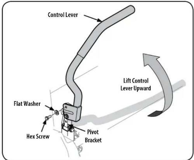
Figure 4
- Slide the flat washer onto the hex screw. From the outside, insert the hex screw with washer through the control lever slot and the hole of the pivot bracket. See Figure 4. Using a 1/2" wrench snug the screw, but do not fully tighten.
- Note the relative position of the control lever to the pivot bracket, then repeat the previous steps to reposition the other control lever in approximately the same position.

CAUTION
Torque the screws down tightly to prevent the control levers from slipping out of position.
- Refer to "Adjusting the Drive Control Levers" in the Maintenance & Adjustments for instructions on the final adjustment of the levers.
Connecting the Battery Cables

WARNING
Battery posts, terminals, and related accessories contain lead and lead compounds, chemicals known to the State of California to cause cancer and reproductive harm. Wash hands after handling.

CAUTION
When attaching battery cables, always connect the POSITIVE (Red) wire to its terminal first, followed by the NEGATIVE (Black) wire.
For shipping reasons, both battery cables on your equipment may have been left disconnected from the terminals at the factory. To connect the battery cables, proceed as follows:
NOTE: The positive battery terminal is marked Pos. (+). The negative battery terminal is marked Neg. (-).
NOTE: If the positive battery cable is already attached, skip ahead to step 2.
- Remove the plastic cover, if present, from the positive battery terminal and attach the red cable to the positive battery terminal (+) with the bolt and hex nut. See Figure 5.
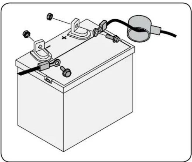
natural_image
Diagram of a battery with attached circuit components and wiring (no text or labels)Figure 5
- Remove the plastic cover, if present, from the negative battery terminal and attach the black cable to the negative battery terminal (−) with the bolt and hex nut. See Figure 5.
- Position the red rubber boot over the positive battery terminal to help protect it from corrosion.
NOTE: If the battery is put into service after the date shown on top or side of battery, charge the battery as instructed in the Service and Maintenance section of this Operator's Manual prior to operating the riding mower.
ASSEMBLY
Lower Deck Discharge Chute Deflector
WARNING
Never operate the mower deck without the chute deflector installed and in the down position.
The discharge chute deflector must be installed before operating the mower.
- Remove the keys that are attached with a zip tie to the chute bracket.
- Remove the carriage screws, flange lock nuts and flat washers from the hardware pack in your manual bag. See Figure 6.
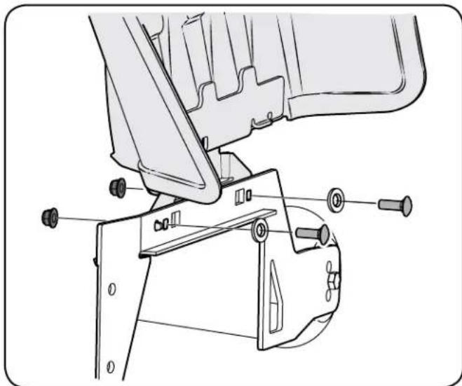
natural_image
Technical line drawing of a mechanical assembly with bolts and brackets (no text or symbols)Figure 6
- With the previously removed hardware, install the chute deflector on the deck as shown in Figure 6.
Checking Tire Pressure
WARNING
Do not overinflate tires. Check sidewall of tires for maximum psi. Equal tire pressure should be maintained at all times.
The tires on your riding mower may be over inflated for shipping purposes. Reduce the tire pressure before operating the riding mower. Check sidewall of tires for maximum psi.
Adjusting the Gauge Wheels
WARNING
Keep hands and feet away from the discharge opening of the cutting deck.
NOTE: The deck gauge wheels are an anti-scalp feature of the deck and are not designed to support the weight of the cutting deck.
The mower deck cutting height can be set in any of six height settings using the riding mower's deck lift handle. The deck heights range from 1- 12 " to 4". The deck gauge wheel position should be approximately 14 " to 12 " above the ground when the deck is set in the desired height setting.
Using the lift handle, set the deck in the desired height setting, then check the gauge wheel distance from the ground below. If necessary adjust as follows:
- Visually check the distance between the front gauge wheels and the ground. If the gauge wheels are near or touching the ground, they should be raised. If more than 12 " above the ground, they should be lowered.
- Remove the lock nut securing one of the front gauge wheel hex screws to the deck. Remove the gauge wheel, hex screw and spacer. Refer to Figure 7.
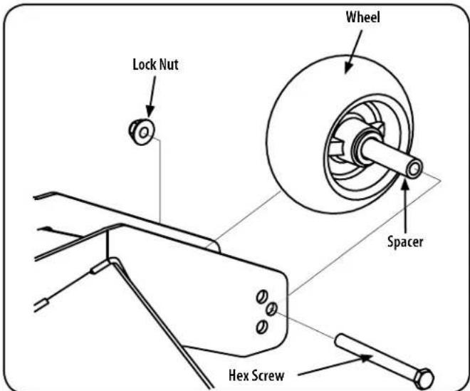
Figure 7
- Insert the hex screw into the one of three index holes in the front gauge wheel bracket that will give the gauge wheel a 14-12 " clearance with the ground.
- Note the index hole of the just adjusted wheel, and adjust the other front gauge wheel into the respective index hole of the other front gauge wheel bracket.
ASSEMBLY
Adjusting the Seat
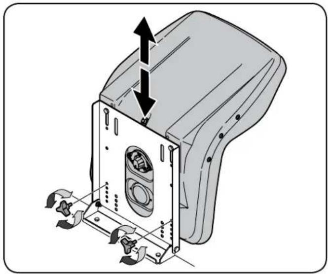
To adjust the position of the seat, rotate the seat forward and locate the two adjustment knobs on the front of the seat pan. Refer to Figure 8.
natural_image
Technical illustration of a mechanical device with internal components and directional arrows indicating movement (no text or symbols)Figure 8
Rotate the clamp knobs to the left and remove them, slide the seat forward or backward and re-insert the clamp knobs into one of the four available positions on the seat pan and into the seat, then tighten securely. Make sure the seat is locked into position before operating the tractor. See Figure 8
Gas and Oil
Fuel Recommendations
Use automotive gasoline (unleaded or low leaded to minimize combustion chamber deposits) with a minimum of 87 octane. Gasoline with up to 10% ethanol or 15% MTBE (Methyl Tertiary Butyl Ether) can be used. Never use an oil/gasoline mixture or dirty gasoline. Avoid getting dirt, dust, or water in the fuel tank. DO NOT use E85 gasoline.
- Refuel in a well-ventilated area with the engine stopped. Do not smoke or allow flames or sparks in the area where the engine is refueled or where gasoline is stored.
- Do not overfill the fuel tank. After refueling, make sure the tank cap is closed properly and securely.
- Be careful not to spill fuel when refueling. Spilled fuel or fuel vapor may ignite. If any fuel is spilled, make sure the area is dry before starting the engine.
- Avoid repeated or prolonged contact with skin or breathing of vapor.
Adding Fuel
WARNING
Use extreme care when handling gasoline. Gasoline is extremely flammable and the vapors are explosive. Never fuel the riding mower indoors or while the engine is hot or running. Extinguish cigarettes, cigars, pipes and other sources of ignition.
- Be sure engine is outdoors and in a well-ventilated area.
- Clean area around the fuel fill cap and remove the fuel fill cap.
- Using an approved red GASOLINE container, add fuel slowly, being careful to avoid spilling.
- Fill the tank until the fuel reaches the bottom of the fuel tank neck.
- Replace the fuel cap and tighten securely. Wipe up spilled fuel before starting engine. If fuel is spilled DO NOT start engine. Move riding mower away from area of spillage. Avoid creating any source of ignition until fuel vapors are gone.
Checking and Adding Oil
Your riding mower is shipped with oil in the engine. However, you MUST check the oil level before operating. Check and add the oil as instructed in your Engine Operator's Manual.
Smart Lawn App Bluetooth® Activation




Take command of your lawn care with the Bluetooth® enabled Smart Lawn App from Craftsman. Maintenance tips, weather tracking and more — everything you need to keep the best yard on the block is now in one place.
Smart Lawn also provides step-by-step instructions and video tutorials to show you how to keep your riding mower running right. Plus, you can order the parts you need directly from the app. The app also tracks the charge of your riding mower battery, as well as the state of other key replacement components like oil, blade and air filter.
Connect your Bluetooth® enabled riding mower by downloading the FREE Craftsman Smart Lawn App to begin using all of the new connectivity features of your Craftsman rider! Download it for FREE from the App Store or Google Play (works with devices running iOS 9, Android 4.4 and later versions).
Once you've created your account, the app will prompt you to enter your riding mower's model number and serial number barcodes. Next it will attempt to connect with the riding mower via Bluetooth®.
Set your smartphone Bluetooth® setting to the 'ON' position. In order to sync your phone to the riding mower, turn on the engine, or turn the key to the 'ON' position. Remember to turn the key to the 'OFF' position after you connect so as not to drain the battery charge (if not running the riding mower).
If you have further questions, call our Craftsman help line at 1-888-331-4569.
OPERATION
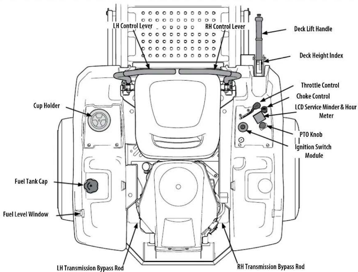
Figure 9
Now that you have set up your riding mower, it's important to become acquainted with its controls and features. Refer to Figure 9.
NOTE: References to LEFT, RIGHT, FRONT, and REAR indicate that position on the riding mower when facing forward while seated in the operator's seat.
NOTE: References to LEFT, RIGHT, FRONT, and REAR indicate that position on the tractor when facing forward while seated in the operator's seat.
RH and LH Drive Control Levers
The RH and LH control levers are located on each side of the operator's seat. These hinged levers pivot outward to open space to permit the operator to either sit in the tractor seat, or to dismount the tractor. The levers must be fully opened out and in the neutral position to start the tractor engine. When the levers are fully outward, the parking brake is also engaged.
Each lever controls the respective RH or LH transmission. Consequently, these levers control all of the movements of the tractor. Driving and steering utilizing these control levers is quite different from conventional tractors, and will take some practice to master. Refer to Operation for instructions on using the control levers.
Cup Holder
The cup holder is located to the left of the operator's seat on the LH console.
Throttle Control
The throttle control is located on the RH console. When set in a given position, a uniform engine speed will be maintained.
Push the throttle control handle forward to increase the engine speed. The tractor is designed to operate with the throttle control in the fast position (full throttle) when the tractor is being driven and the mower deck is engaged.
Pull the throttle control handle rearward to decrease the engine speed.

OPERATION
Choke Control
The choke control is located on the RH console. The choke control determines the position of the engine choke. Pull the knob out to choke the engine; push the knob in to open the choke.

Ignition Switch Module
WARNING
Never leave a running machine unattended. Always disengage PTO, set parking brake, stop engine and remove key to prevent unintended starting.
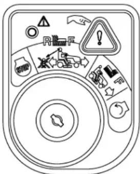
To start the engine, insert the key into the ignition switch and turn clockwise to the START position. Release the key into the NORMAL MOWING MODE position once the engine has fired.
To stop the engine, turn the ignition key counterclockwise to the STOP position.
CAUTION
Prior to operating the tractor, refer to both Safety Interlock Switches and Starting The Engine in the Operation section of this manual for detailed instructions regarding the Ignition Switch Module and operating the tractor in REVERSE CAUTION MODE
Deck Height Index
The deck height index consists of several holes located on the front of the RH console. Each hole corresponds to a 1/4" change in the deck height position ranging from 1" at the lowest notch to 4" at the highest notch. The highest notch is also the transport position and the lowest position is the deck removal/installation position
NOTE: Do not cut grass in the deck removal/installation position. Doing so is detrimental to the belt life.
Deck Lift Handle
The deck lift handle is located on the front of the RH console, and is used to raise and lower the mower deck.
Depress the button on the end of the handle and push downward to lower the deck, or pull upward to raise the deck. When the desired height is attained, secure the pin in the desired index hole and release the button on the handle.
NOTE: Make certain the deck is secured and the pin is fully inserted into the deck height index. The pin is keyed to help keep it in place and fits into the slotted holes on the deck height index.
NOTE: The deck lift handle must always be above the pin, never hang the deck lift handle from the pin when mowing.
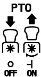
Power Take-Off (PTO) Knob
The PTO knob is located on the RH console to the left of the hour meter/indicator panel.
The PTO knob operates the electric PTO clutch mounted on the bottom of the engine crankshaft. Pull the knob upward to engage the PTO clutch, or push the knob downward to disengage the clutch.
The PTO knob must be in the "disengaged" position when starting the engine.
Transmission Bypass Rods
The transmission bypass rods (one for each the RH and LH transmission) are located on the rear of the tractor, just inside each rear wheel.
When engaged, the two rods open a bypass within the hydrostatic transmissions, which allows the tractor to be pushed short distances by hand. Refer to the Assembly & Set-Up section for instructions on using the bypass feature.
CAUTION
Never tow your tractor. Towing the tractor with the rear wheels on the ground may cause severe damage to the transmissions.
Fuel Tank Cap
The fuel tank cap is located near the middle of the LH console. Turn the fill cap to remove. The fuel cap is tethered to the tractor to prevent its loss. Do not attempt to remove the cap from the tractor. Fill tank to the bottom of the filler neck, allowing some space in the tank for fuel expansion. Do not overfill the tank.
Push the cap downward on the fuel tank fill neck and turn clockwise until it clicks to tighten. Always re-install the fuel cap tightly onto the fuel tank after removing.
WARNING
Never fill the fuel tank when the engine is running. If the engine is hot from recently running, allow to cool for several minutes before refueling. Highly flammable gasoline could splash onto the engine and cause a fire.
Fuel Level Window
The fuel level windows is located on the outside of the LH console and shows the level of fuel in the gas tank.
Transmission Oil Expansion Reservoir
The transmission oil expansion reservoir is connected by hoses to the RH and LH transmission assemblies, and is located behind the seat box. The function of the reservoir is to hold the natural expansion of transmission oil that occurs as the transmission warms up during operation. See the Assembly & Set-Up section for more information on the transmission oil expansion reservoir.
OPERATION
LCD Service Minder & Hour Meter w/ Smart Lawn App Bluetooth® Activation
When the ignition key is rotated out of the STOP position but not into the START position, the LCD Service Minder and Hour Meter will briefly display the battery voltage, followed by the tractor's accumulated hours.
NOTE: Hours of tractor operation ☒ are recorded only when the engine is running. If the riding mower is equipped with headlights, the lights will remain on until the riding mower is turned off.
Smart Lawn App


The app's automated maintenance dashboard and log will help you keep your machine running at peak performance and protect your investment by tracking total hours across the lifetime of your equipment.
Receive alert notifications when it's time to perform essential maintenance tasks. Your dashboard provides real time monitoring and indicates when it's time for you to check or change the oil, air filter, blades or battery. The app also enables you to locate and contact service centers, access step-by-step instructions to perform routine maintenance and purchase replacement parts directly from your mobile device.
Change Oil
The LCD will display the letters "CHG", followed by the letters "OIL", followed by the letters "SOON", then finally followed by the meter's accumulated time. "CHG/OIL/SOON/TIME" will alternate on the display for 7 minutes after the meter reaches 50 hours. This oil service minder interval will occur every 50 hours. Before the interval expires, change the engine oil as instructed in the Maintenance section of the Engine Operator's Manual.
Low Oil (If so equipped)
The letters "LO" followed by the letters "OIL", then followed by the meter's accumulated time will indicate the tractor is low on oil. When an engine is not running and immediately after the engine is started the oil pressure may be low. This can trigger the "LO" "OIL" text. This is normal. If the low oil indication persists stop the tractor immediately and check the engine oil level as instructed in the Engine Operator's Manual.
NOTE: The "LOW OIL" function only works if the engine is equipped with an oil pressure switch.
Low Battery
At startup, the battery voltage is briefly displayed then changes to accumulated hours. The letters "LO" will display followed by the letters "BATT" and then followed by the meter's accumulated time. "LO/BATT/TIME" is displayed on the LCD when the voltage drops below 11.5 volts. When this occurs, the battery is in need of a charge or the engine's charging system is not generating sufficient amperage. Charge the battery as instructed in the Service section of this manual or have the charging system checked by your local service dealer.
Air Filter Service
The letters "CLN" will display, followed by the letters "AIR", followed by "FILT", then followed by the meter's accumulated time. "CLN/AIR/FILT/TIME" will alternate on the display for 7 minutes after the meter reaches 50 hours. This air filter service minder time interval will be every 50 hours. On intervals that are common with oil service, the oil message will be displayed first followed by the air filter message.
General Safety
- RECEIVE INSTRUCTION — Entirely read this operator's manual. Learn to operate this machine SAFELY. Do not risk INJURY or DEATH. Allow only those who have become competent in its usage to operate this tractor.
- Before starting the engine or beginning operation, be familiar with the controls. The operator should be in the operator's seat. The PTO switch must be in the disengaged position and the RH and LH drive control levers moved to the neutral position engaging the parking brake.
- Keep all shields in place. Keep away from moving parts.
- NO RIDERS! Keep all people and pets a safe distance away. Look behind and down to both sides of the tractor before and while backing up.
- DO NOT direct the mower discharge at people. Never walk or stand on the discharge side of the mower when the engine is running. Turn off the PTO if another person approaches while you are operating the mower.
- Avoid slopes where possible. Never operate on slopes greater than 15^ . Slopes with a greater incline present dangerous operating conditions. Tractors can be rolled over. Always mow across slopes, never up and down the slope. Avoid turning downhill if possible, start at the bottom and work up to the top. Use extra care and go slowly when turning downhill. Control the speed and direction of the zero turn machine "primarily" with the speed/directional control (lap bar) of the downhill side of the machine, i.e., maintain the uphill side lap bar "essentially" in a fixed position.
- Before leaving the operator's seat: Shut off the PTO, move the RH and LH drive control levers fully outward in the neutral position, engage the parking brake, shut off the engine and remove the ignition key. Wait for all movement to stop before servicing or cleaning.
- When operating this mower, in the forward direction, do not allow the steering levers to return to neutral on their own. Operate the drive control levers smoothly and avoid any sudden movements of the levers when starting and stopping. Keep a firm grip on the control levers.
- Be careful when operating near gravel paths and roadways. Stop the blades and tractor motion and wait for vehicles to pass before operating along the road.
- Do not operate the tractor with the mower deck removed. Removal of the deck will change the balance of the tractor, and could contribute to a tractor rollover.
- Avoid operation on traction surfaces that are unstable; use extreme caution if the surface is slippery. Always remove debris and other objects from the area to be mowed - debris and loose grass will reduce traction.
- Mow only in daylight or good artificial light.
- Watch for holes, sprinkler heads, and other hidden hazards.
- Avoid driving too close to trees, creeks, ditches, sand traps, and other obstacles.
- Slow down before turning and come to a complete stop before any zero turn maneuver.
- If you hit a solid object while mowing, turn off the PTO, place the steering levers in the neutral, opened-out position, move the throttle to slow, set the parking brake, shut off the engine, and take the key from the ignition switch. Inspect for damage. Repair the damage. Make sure the blades are in good condition and that the blade bolts are tight before restarting the engine.
- Do not stop the tractor or park the tractor over combustible materials such as dry grass, leaves, debris, etc.
- Keep the mower and especially the engine and hydraulic components clean and free of grease, grass, and leaves to reduce the chance of fire and permit proper cooling.
- Do not fill the fuel tank when the engine is running or while the engine is hot. Allow the engine several minutes to cool before refueling. Tighten the fuel cap securely.
OPERATION
Checking the Safety Interlock Circuits
Periodically check the safety interlock circuits to ensure they are working properly. If a safety circuit is not working as designed, contact your authorized service dealer to have the tractor inspected. DO NOT operate the tractor if any safety circuit is not functioning properly. To check the safety circuits, proceed as follows:
- Pull the PTO switch upward to the engaged position. Momentarily turn the ignition switch to the START ⏻ position; the engine should not crank.
- Move both control levers fully inward in the neutral position; then lift upward from the operator's seat. The engine should stop.
- With both control levers fully outward in the neutral/parking brake engaged position, engage the PTO. Lift upward from the operator's seat; the engine should stop.
- Start the tractor and move the control levers inward to the neutral operating position. Engage the PTO and move both control lever slowly into the slow reverse position with the key in the NORMAL MOWING; the PTO should disengage and the mower deck should stop.
Before Operating Your Tractor
- Before you operate the tractor, study this manual carefully to familiarize yourself with the operation of all the instruments and controls. It has been prepared to help you operate and maintain your tractor efficiently.
- Fill the fuel tank with only clean, fresh, unleaded gasoline with a pump sticker octane rating of 87 or higher and 10% ethanol maximum. When the fuel reaches one inch from the top of the tank, stop. DO NOT OVERFILL. Space must be left for expansion.
- Unleaded gasoline is recommended because it leaves less combustion chamber deposits and reduces harmful exhaust emissions. Leaded gasoline is not recommended and must not be used where exhaust emissions are regulated. NOTE: Purchase gasoline in small quantities. Do not use gasoline left over from the previous season, to minimize gum deposits in the fuel system.
- Gasohol (up to 10% ethyl alcohol, 90% unleaded gasoline by volume) is an approved fuel. Other gasoline/alcohol blends are not approved.
- Methyl Tertiary Butyl Ether (MTBE) and unleaded gas blends (up to a maximum of 15% MTBE by volume) are approved fuels. Other gasoline/ether blends are not approved.
- Check the engine oil level. Refer to the Engine Operator's manual for instructions on checking the engine oil level.
- Clean the air cleaner element if necessary.
- Check the tire inflation pressures. See the tire side wall for proper inflation pressures.
NOTE: New tires are overinflated in order to properly seat the bead to the rim. - Check that all nuts, bolts and screws are tight.
- Check the tension of the deck drive belts.
a. Remove the deck cover
b. The tension of the deck drive belts are maintained by a spring mechanism that adjusts for wear and stretch.
c. Examine the belts for cuts, fraying, and excessive wear. Replace if any of these are detected.
d. Replace the deck cover. -
Check if deck is level. When correctly adjusted the mower deck should be level side to side, and the front of the deck should be approximately 1/4" lower than the rear of deck. If deck needs to be leveled, refer to the Service and Maintenance section.
-
Lubricate all pivot points listed in the Service and Maintenance section.
-
Adjust the seat for operator's maximum comfort, visibility and for maintaining complete control of the tractor.
Safety Interlock System
This tractor is equipped with a safety interlock system for the protection of the operator. If the interlock system should ever malfunction, do not operate the tractor. Contact your authorized service dealer.
- The safety interlock system prevents the engine from cranking or starting unless the RH and LH drive control levers are moved fully outward in the neutral position — which engages the parking brake — and the PTO is disengaged.
- The safety interlock system will shut off the engine if the operator leaves the seat before the RH and LH drive control levers are fully outward in the neutral position engaging the parking brake.
- The safety interlock system will shut off the engine if the operator leaves the seat with the PTO engaged, regardless of whether the RH and LH drive control levers are fully outward in the neutral position engaging the parking brake. NOTE: The PTO switch must be moved to the "OFF" position to restart the engine.
- The safety interlock system will shut off the PTO and the mower blades will stop if both drive control levers are moved into the reverse position. To restart the blades the PTO must be moved to the "OFF" position and then back to the "ON" position.
Starting the Engine
WARNING
This tractor is equipped with a safety interlock system designed for the protection of the operator. Do not operate the tractor if any part of the interlock system is malfunctioning. Periodically check the functions of the interlock system for proper operation.
WARNING
For personal safety, the operator must be sitting in the tractor seat when starting the engine.
- Operator must be sitting in the tractor seat with the RH and LH drive control levers fully outward in the neutral position engaging the parking brake.
- Make certain the PTO switch is in the disengaged (down) position.
- Pull the choke knob (if equipped) up into the CHOKE position or move the throttle/choke control (if equipped) into the CHOKE position. NOTE: If the engine is warmed up, it may not be necessary to choke the engine.
- Move the throttle control (if equipped) to midway between its slow and fast positions.
- Turn the ignition key clockwise to the START position. After the engine starts, release the key. It will return to the NORMAL MOWING position.
CAUTION
Do NOT hold the key in the START ☐ position for longer than ten seconds at a time. Doing so may cause damage to your engine's electric starter.
- Once the engine warms up, push the choke knob down into the OFF position.
OPERATION
NOTE: Do NOT leave the throttle/choke control (if equipped) or choke control (if equipped) in the CHOKE position while operating the tractor. Doing so will result in a "rich" fuel mixture and cause the engine to run poorly.
Cold Weather Starting
When starting the engine at temperatures near or below freezing, ensure the correct viscosity motor oil is used in the engine and the battery is fully charged. Start the engine as follows:
- Be sure the battery is in good condition. A warm battery has much more starting capacity than a cold battery.
- Use fresh winter grade fuel. Winter grade gasoline has higher volatility to improve starting. Do not use gasoline left over from summer.
- Follow the previous instruction for Starting the Engine.
Using Jumper Cables To Start Engine
WARNING
Batteries contain sulfuric acid and produce explosive gasses. Make certain the area is well ventilated, wear gloves and eye protection, and avoid sparks or flames near the battery.
If the battery charge is not sufficient to crank the engine, recharge the battery. If a battery charger is unavailable and the tractor must be started, the aid of a booster battery will be necessary. Connect the booster battery as follows:
- Connect the end of one cable to the disabled tractor battery's positive terminal; then connect the other end of that cable to the booster battery's positive terminal.
- Connect one end of the other cable to the booster battery's negative terminal; then connect the other end of that cable to the frame of the disabled tractor, as far from the battery as possible.
- Start the disabled tractor following the normal starting instructions previously provided; then disconnect the jumper cables in the exact reverse order of their connection.
- Have the tractor's electrical system checked and repaired as soon as possible to eliminate the need for jump starting.
Stopping the Engine
- Place the PTO switch in the OFF (down) position.
- Move RH and LH drive control levers fully outward in the neutral position engaging the parking brake.
- Move the throttle control (if equipped) or throttle/choke control (if equipped) to the SLOW position and allow the engine to idle for about one minute.
- Turn the ignition key to the STOP position and remove the key from the ignition switch.
NOTE: Always remove the key from the ignition switch to prevent accidental starting or battery discharge if the equipment is left unattended.
Practice Operation (Initial Use)
Operating a zero-turn tractor is not like operating a conventional type riding tractor. Although and because a zero turn tractor is more maneuverable, getting used to operating the control levers takes some practice.
We strongly recommend that you locate a reasonably large, level and open "practice area" where there are no obstructions, pedestrians, or animals. You should practice operating the tractor for a minimum of 30 minutes.
Carefully move (or have moved) the tractor to the practice area. When performing the practice session, the PTO should not be engaged. While practicing, operate the tractor at approximately 1/2-3/4 throttle and at less than full speed in both forward and reverse.
Use protective equipment for eyes, hands, hearing, feet, legs, head and other areas of the body if needed — safety eye glasses, gloves, earplugs, boots, hats, etc.
WARNING
Hearing Protection is required for all operator exposure exceeding two (2) hours.
Carefully practice maneuvering the tractor using the instructions in the following section "Driving the Tractor." Practice until you are confident that you can safely operate the tractor.
Driving the Tractor
WARNING
Avoid sudden starts, excessive speed and sudden stops.
- Adjust the operator's seat to the most comfortable position that allows you to operate the controls. See seat adjustment in the Assembly & Set-Up section.
- Move the RH and LH drive control levers inward in the neutral position. Refer to Figure 10.
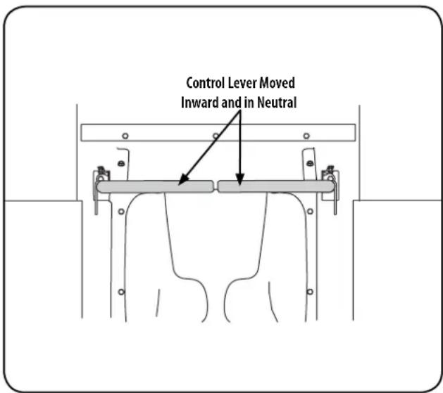
Figure 10
NOTE: If the control levers are not even in the neutral position, refer to Service and Maintenance for instructions to adjust the levers so that they are even.
OPERATION
- Move the throttle control lever (if equipped) or throttle/choke control lever forward to the full throttle position.
NOTE: Although the tractor's engine is designed to run at full throttle, when performing a practice session the tractor must be operated at less than full throttle. This only applies to practice.
WARNING
Always maintain a firm grip on the control levers. DO NOT release the control levers to slow or stop the tractor; move levers to neutral position using your hands.
- To drive the tractor, firmly grasp the respective drive control levers with your right and left hands and continue with Driving the Tractor Forward on the following page.
Driving the Tractor Forward
WARNING
Keep all movement of the drive control levers slow and smooth. Abrupt movement of the control levers can affect the stability of the tractor and could cause the tractor to flip over, which may result in serious injury or death to the operator.
- Slowly and evenly move both drive control levers forward. The tractor will start to move forward. See Figure 11.
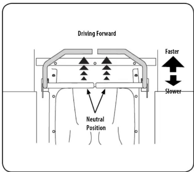
Figure 11
- As the control levers are pushed farther forward the speed of the tractor will increase.
- To slow the tractor move the controls lever rearward to attain the desired speed, or move the levers to the neutral position to stop the tractor.
WARNING
Always maintain your grasp on the drive control levers. Do not release the levers to slow the tractor or to return to neutral.
Turning the Tractor While Driving Forward
WARNING
When reversing the direction of travel, we recommend performing gradual 'U' turns where possible. Sharper turns increase the possibility of turf defacement, and could affect control of the tractor. ALWAYS slow the tractor before making sharp turns.
To turn the tractor while driving forward, move the control levers as necessary so that one lever is rearward of the other. The tractor will turn in the direction of the rearward control lever.
- To turn to the left, move the left drive control lever rearward of the right lever. See Figure 12.
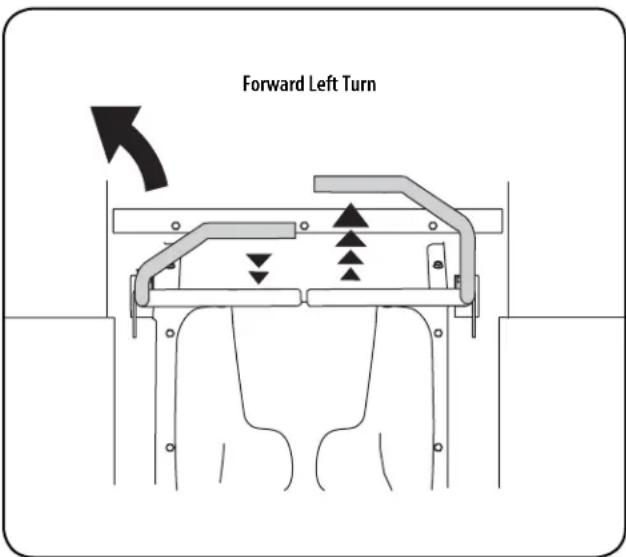
Figure 12
- To turn to the right, move the right drive control lever rearward of the left lever. See Figure 13.
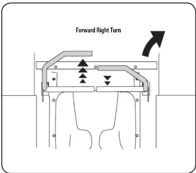
Figure 13
OPERATION
- The greater the fore-to-aft distance between the two levers, the sharper the tractor will turn.
- To execute a "pivot turn," move the turn side drive control lever to the neutral position, while moving the other control lever forward.
NOTE: Making a "pivot turn" on grass will greatly increase the potential for defacement of the turf.
Driving the Tractor In Reverse

WARNING
Always look behind and down on both sides of the tractor before backing up. Always look behind while traveling in the reverse direction.
- Slowly and evenly move both drive control levers rearward. The tractor will start to move in the reverse direction. See Figure 14.
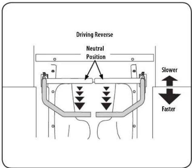
Figure 14
- As the control levers are pushed farther rearward the speed of the tractor will increase.
- To slow the tractor move the controls lever forward to attain the desired speed, or move the levers to the neutral position to stop the tractor.
Turning While Driving Rearward
To turn the tractor while driving rearward, move the control levers as necessary so that one lever is forward of the other. The tractor will turn in the direction of the forward control lever.
- To turn to the left while traveling in reverse, move the left drive control lever forward of the right lever. See Figure 15.
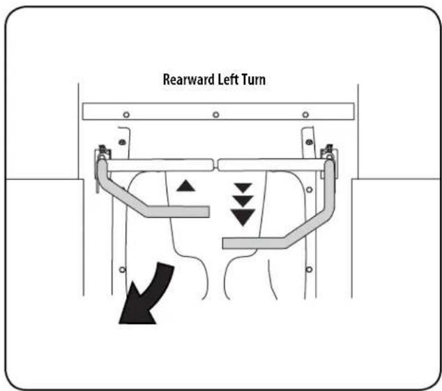
Figure 15
- To turn to the right while traveling in reverse, move the right drive control lever forward of the left lever. See Figure 16.
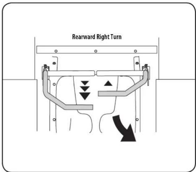
Figure 16
- The greater the fore-to-aft distance between the two levers, the sharper the tractor will turn.
- To execute a "pivot turn," move the turn side drive control lever to the neutral position, while moving the other control lever rearward.
NOTE: Making a "pivot turn" on grass will greatly increase the potential for defacement of the turf.
OPERATION
Reverse Caution Mode
The REVERSE CAUTION MODE position of the key switch module allows the tractor to be operated in reverse with the blades (PTO) engaged.
NOTE: Mowing in reverse is not recommended.
WARNING
Use extreme caution while operating the tractor in the REVERSE CAUTION
MODE . Always look down and behind before and while backing. Do not operate the tractor when children or others are around. Stop the tractor immediately if someone enters the area
To use the REVERSE CAUTION MODE

NOTE: The operator MUST be seated in the tractor seat.
-
Start the engine as instructed on the previous page.
-
Turn the key from the NORMAL MOWING

REVERSE CAUTION MODE (Yellow) position of the key switch module. See Figure 17.
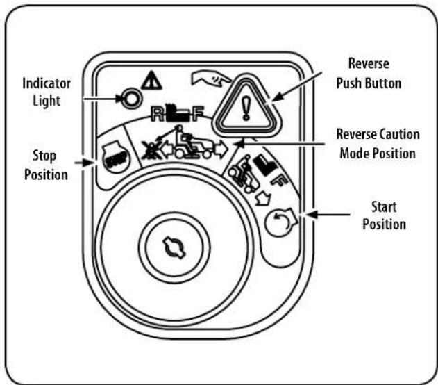
Figure 17
- Press the REVERSE PUSH BUTTON (Orange, Triangular Button) at the top, right corner of the key switch module. The red indicator light at the top, left corner of the key switch module will be ON while activated. See Figure 17.
- Once activated (indicator light ON), the tractor can be driven in reverse with the cutting blades (PTO) engaged.
- Always look down and behind before and while backing to make sure no children are around. After resuming forward motion, return the key to the NORMAL MOWING position.
The REVERSE CAUTION MODE will remain activated until:
a. The key is placed in either the NORMAL MOWING
position or
b. The operator leaves the seat.
Executing a Zero Turn
WARNING
When executing a zero turn, the tractor MUST BE STOPPED. Executing a zero turn while the e tractor is moving can significantly reduce your control of the tractor and will cause severe turf defacement to occur.
- Stop the forward or reverse motion of the tractor by moving the two drive control levers to neutral.
- To turn clockwise, move the left control lever forward while simultaneously moving the right control lever rearward. See Figure 18.
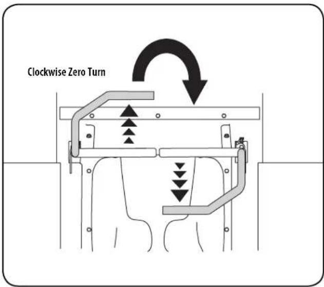
Figure 18
- To turn counterclockwise, move the right control lever forward while simultaneously moving the left control lever rearward. See Figure 19.
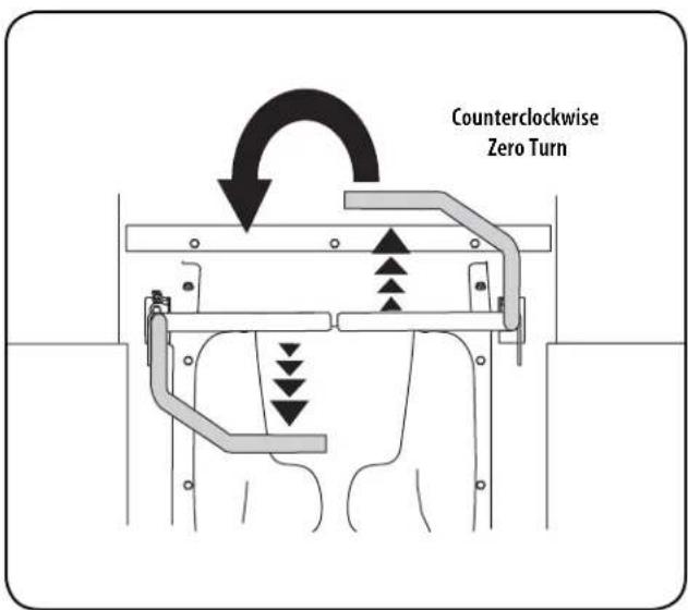
Figure 19
OPERATION
Executing a "Y" Maneuver
For low traction conditions, follow these procedures for zero turns (the "Y-maneuver"):
To turn clockwise (front of machine moves toward RIGHT) when traveling FORWARD:
- Come to a stop,
- Then slowly move both lap bars rearward (no more than 12 maximum reverse speed) to initiate REVERSE travel,
- Then slowly move the LEFT lap bar forward while maintaining the RIGHT lap bar in the rearward travel position.
- To stop the turn and re-initiate FORWARD travel, slowly move the RIGHT lap bar from the REVERSE travel position to a FORWARD travel position equal to that of the LEFT lap bar.
- For counterclockwise turns, reverse the above procedure.
Stopping the Tractor
- Move both drive control levers to the neutral position to stop the motion of the tractor.
- Push the PTO knob downward to the disengaged position.
- Use the deck lift handle to raise the deck to its highest position by depressing the button at the end of the handle and pulling upwards. Make sure the latch engages on the pin. See Figure 20.
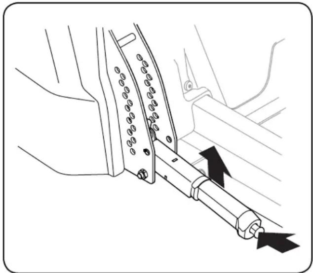
natural_image
Diagram of a mechanical device with arrows indicating motion or force direction (no text or symbols)Figure 20
- If dismounting the tractor, move the drive control handles fully outward in the neutral position engaging the parking brake, move the throttle control lever to the mid-throttle or SLOW position, turn the ignition switch to STOP and remove the key from the switch.
WARNING
Do not leave the seat of the tractor without disengaging the PTO, moving drive control levers fully outward in the neutral position engaging the parking brake. If leaving the tractor unattended, turn the ignition key off and remove key.
Driving On Slopes
Refer to the slope gauge in the Safe Operation Section to help determine slopes where you may not operate safely.
WARNING
Do not operate on inclines with a slope in excess of 15 degrees (a rise of approximately 2^-12 feet every 10 feet). The tractor could overturn and cause serious injury.
- Always drive across slopes, never up and down. Control the speed and direction of the tractor using primarily the control lever on the downhill side of the tractor, with the uphill control lever remaining essentially in a fixed position.
- Avoid turning downhill if possible. Start at the bottom of a slope and work upward. Always slow down before turning.
- Use extra care and go slowly when turning downhill.
Operating The PTO
Operate the PTO clutch as follows:
NOTE: During your units initial break-in period, in order to engage the PTO and avoid engine stall, allow the engine to warm before engaging the PTO. Break-In period varies depending on your engine.
- Move the throttle control lever to the FAST position.
- Pull the PTO knob upward to the ENGAGED position.
- The operator must remain in the tractor seat at all times. If the operator should leave the seat without disengaging the PTO, the tractor's engine will shut off.
- The PTO clutch cannot be operated when the tractor is driving in the reverse direction. The PTO will disengage when both drive control levers are moved to the reverse position and will re-engage when one (or both) control lever(s) is moved to the neutral or forward position.
Mowing
WARNING
Make certain the area to be mowed is free of debris, sticks, stones, wire or other objects that can be thrown by the rotating blades.
NOTE: Do not engage the mower deck when lowered in grass. Premature wear and possible failure of the "V" belt and PTO clutch will result. Fully raise the deck or move to a non grassy area before engaging the mower deck.
- Mow across slopes, not up and down. If mowing a slope, start at bottom and work upward to ensure turns are made uphill.
- On the first pass pick a point on the opposite side of the area to be mowed.
- Engage the PTO and move the throttle control to the FAST position.
-
Lower the mower deck to the desired height setting using the deck lift handle.
-
Slowly and evenly push the RH and LH drive control levers forward to move the tractor forward, and keep the tractor headed directly toward the alignment point.
NOTE: The speed of the tractor will affect the quality of the mower cut. Mowing at full speed will adversely affect the cut quality. Control the ground speed with the control levers.
OPERATION
- When approaching the other end of the strip, slow down or stop before turning. A U-turn is recommended unless a pivot or zero turn is required.
- Align the mower with an edge of the mowed strip and overlap approximately 3".
- Direct the tractor on each subsequent strip to align with a previously cut strip.
- To prevent rutting or grooving of the turf, if possible, change the direction that the strips are mowed by approximately 45^ for the next and each subsequent mowing.

WARNING
Be careful when crossing gravel paths or driveways. Disengage the PTO and raise the deck to the highest position before crossing.
NOTE: When stopping the tractor for any reason while on a grass surface, always:
- Place the control levers in the neutral/parking brake engaged position,
- Shut engine off and remove the key.
- Doing so will minimize the possibility of having your lawn "browned" by hot exhaust from your tractor's running engine.
Deck Lift Lever
To raise or lower the cutting deck, depress the button on the end of the handle and push downward to lower the deck, or pull upward to raise the deck, then place it in the hole best suited for your application. To place the deck in the transport position, lift the handle all the way up and hang the top hook on the handle from the upper spacer on the deck height index bracket. See Figure 21.
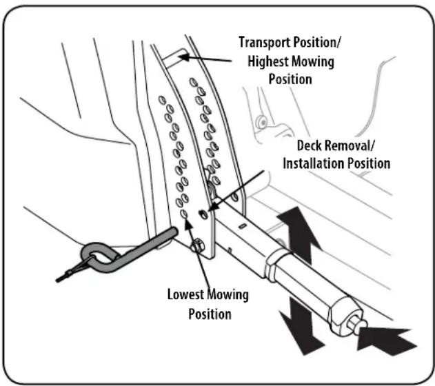
Figure 21
NOTE: Make certain the deck is secured and the pin is fully inserted into the deck height index. The pin is keyed to help keep it in place and fits into the slotted holes on the deck height index.
NOTE: The deck lift handle must always be above the pin, never hang the deck lift handle from the pin when mowing.
SERVICE AND MAINTENANCE
MAINTENANCE SCHEDULE
WARNING
Before performing any type of maintenance/service, disengage all controls and stop the engine. Wait until all moving parts have come to a complete stop. Disconnect spark plug wire and ground it against the engine to prevent unintended starting. Always wear safety glasses during operation or while performing any adjustments or repairs.
Follow the maintenance schedule given below. This chart describes service guidelines only. Use the Service Log column to keep track of completed maintenance tasks. To schedule service from Sears Parts & Repair, call 1-888-331-4569.
Refer to the Engine Operator's Manual for engine maintenance items listed in the table below.
| Interval Item Service Service Log | |||
| Each use 1. Engine intake screens and cooling fans *2. Exhaust manifold, muffler pipe and muffler shields *3. Check/Clean Hood/Dash Panel Louvers *4. Top and underside of deck, under and around spindle covers and belt area *5. Around fuses, wiring and wiring harnesses *6. Around transmission, axle and fans *7. Engine Oil8. Air Filter | 1. Check/Clean2. Check/Clean3. Check/Clean4. Check/Clean5. Check/Clean6. Check/Clean7. Check (See engine manual)8. Clean (See engine manual) | ||
| After first 5 hours | 1. Engine Oil | 1. Change (break-in period). See engine manual | |
| Every 10 hours 1. Battery terminals | 2. Lubrication points3. Blades4. Tires5. Front wheels6. Deck | 1. Clean2. Grease3. Check/Sharpen/Replace as needed4. Check5. Lube6. Check/Clean | |
| Every 25 hours 1. Deck wheels | 2. Deck level/pitch3. Deck spindles | 1. Inspect and lube2. Check3. Lube | |
| Every 50 hours 1. Belts and pulleys | 2. Engine Oil3. Oil Filter4. Air Filter5. Fuel Filter | 1. Check for damage and wear2. Change (See engine manual)3. Replace (See engine manual)4. Clean or change (See engine manual)5. Replace (See engine manual) | |
| Every 100 hours 1. Hardware | 2. Spark plug condition/gap | 1. Check2. Check (See engine manual) | |
| Every season/Before storage 1. Intake Screen | Screen2. Engine Cooling Fans3. Battery terminals4. Lubrication points5. Blades6. Tires7. Front wheels8. Deck9. Deck wheels10. Deck level/pitch11. Deck spindles12. Spark plug condition/gap13. Engine Oil14. Oil Filter | 1. Check/Clean2. Check/Clean3. Clean4. Grease5. Check/Sharpen/Replace as needed6. Check7. Lube8. Check/Clean9. Inspect and lube10. Check11. Lube12. Check (See engine manual)13. Change (See engine manual)14. Replace (See engine manual) | |
| Miscellaneous | 1. Valve lashing ^ | 2. Check and adjust ^ | |
*-- Perform more often in dry conditions and/or when mulching
^ -- Have this item performed by a Sears or other qualified service dealer
SERVICE AND MAINTENANCE
WARNING
Before performing any maintenance or repairs, disengage the PTO, move the drive control levers fully outward in the neutral position, engage the parking brake, stop the engine and remove the key to prevent unintended starting.
Post-Operation Tractor Care
After each operation of the tractor, the following procedures should be implemented to extend the life of your tractor and ensure safe operating conditions.
! DANGER
Failure to follow these recommendations may result in serious injury to yourself or others and may cause damage to the tractor.
Cleaning the Underside of the Deck
Deck Wash System
Your tractor's deck is equipped with a water port on its surface as part of its deck wash system.
Use the deck wash system to rinse grass clippings from the deck's underside and prevent the buildup of corrosive chemicals. Complete the following steps AFTER EACH MOWING:
- Attach the nozzle adapter to a standard garden hose connected to a water supply.
WARNING
Make certain the tractor's discharge chute is directed AWAY from people, your house, garage, parked cars, etc.
- Move the tractor to an area within reach of the hose where the dispersal of wet grass clippings is acceptable to you. Disengage the PTO, engage the parking brake and stop the engine.
- Pull back the lock collar of the nozzle adapter and push the nozzle adapter onto one of the deck wash nozzles at either end of the tractor deck. Release the lock collar to lock the nozzle adapter on the deck wash nozzle. See Figure 22.
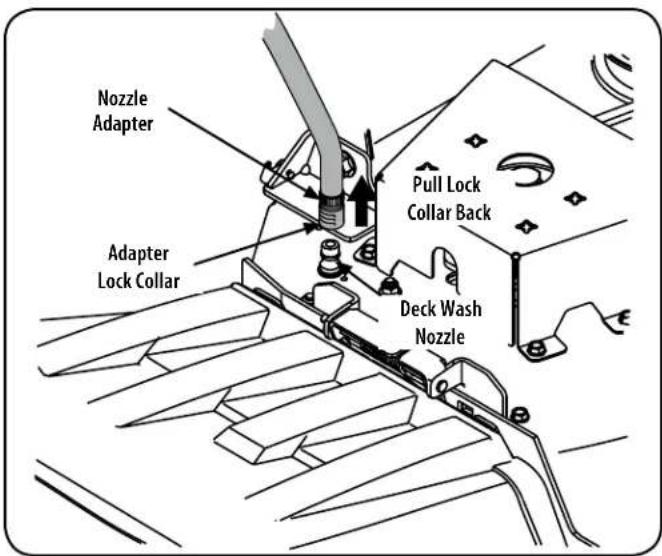
Figure 22
- Turn on the water supply.
- From the tractor operator's seat, start the engine and engage the PTO. Allow to run as needed. Disengage the PTO and stop the engine.
-
Turn off the water supply.
-
Pull back the lock collar of the nozzle adapter to disconnect the nozzle adapter from the deck wash nozzle.
- Repeat the previous steps to clean the deck using the deck wash nozzle at the other end of the deck.
Cleaning the Tractor
WARNING
If the tractor has been recently run, the engine, muffler and surrounding metal surfaces will be hot and can cause burns to the skin. Let the engine cool for at least five minutes Exercise caution to avoid burns.
Your tractor should be cleaned after each use and under certain conditions, i.e. dry conditions and/or mulching situations, additional cleaning may be necessary.
One of the best ways to keep your tractor running efficiently and to reduce fire risk is to regularly remove debris buildup from the tractor. Follow the recommendations below and contact your authorized dealer with any questions.
- Allow the machine to cool in an open area before cleaning.
- Do not use water on any part of the tractor except the underside of the cutting deck. Doing so can cause damage to the tractor's spindle bearings, electrical system and engine, leading to premature failures. The use of compressed air and/or leaf blower will help keep the tractor clean.
- Keep both sides of transmission cooling slots, exhaust manifold, around fuses, all wiring and harnesses, muffler pipe, muffler shield, engine intake screens and cooling fins, etc clear of grass clippings and leaves. See Figure 23.
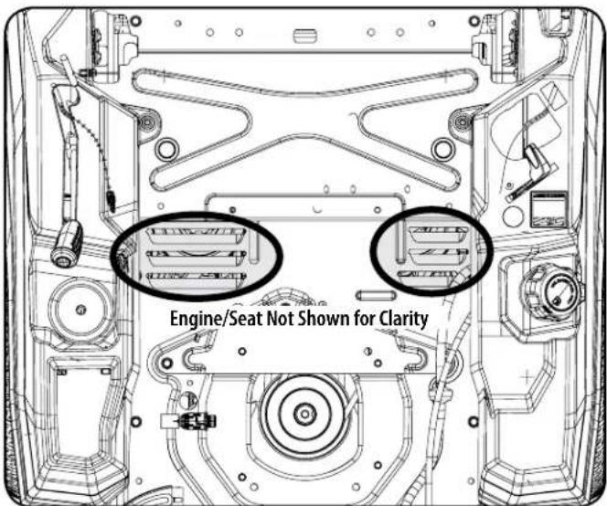
Figure 23
SERVICE AND MAINTENANCE
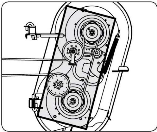
- Clean the top of the mower deck, under the spindle covers and belt area. See Figure 24.
natural_image
Technical line drawing of a mechanical assembly with gears and shafts (no text or symbols)Figure 24
- Clean around and near the transmission, axle and the fan area. See Figure 25.
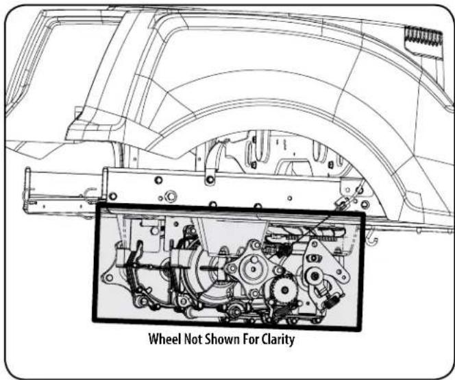
Figure 25
- Debris can accumulate anywhere on the tractor, especially on horizontal surfaces. Additional cleaning may be necessary when mowing in dry conditions or when mulching.
- Fuel leaks/spills, oil leaks/spills and excess lubrication can also become collections sites for debris. Immediate repair and cleaning up oil or fuel spills can help reduce fire hazards.
- In addition to cleaning the tractor before operating and storing, do not attempt to mow unusually tall grass (10" or higher), dry grass (e.g., pasture) or piles of dry leaves. Dry grass or leaves may contact the engine exhaust and/or build up on the mower deck presenting a potential fire hazard.
Storing the Tractor
- Allow the machine to cool in an open area before storing.
- Do not park the tractor near any flammable materials (wood, cloth or chemicals) or any open flames or other potential source of ignition (furnace, water heater or any other type of heater).
- Remove all combustible materials from the tractor before storing. Empty cargo boxes, grass catchers or containers.
- Always shut off fuel flow when storing or transporting if tractor is equipped with a fuel shutoff.
- Check the fuel system (lines, tank, cap and fittings) frequently for cracks or leaks. Repair and clean as necessary.
Engine Maintenance
Refer to the Engine Owner's Manual for all engine maintenance procedures and instructions.
Changing the Engine Oil
WARNING
If the engine has been recently run, the engine, muffler and surrounding metal surfaces will be hot and can cause burns to the skin. Exercise caution to avoid burns.
To complete an oil change, proceed as follows:
- Run the engine for a short time to warm the engine oil. The oil will flow more freely and carry away more impurities. Use care to avoid burns from hot oil.
- Locate the oil drain hose on the left side of the engine. See Figure 26.
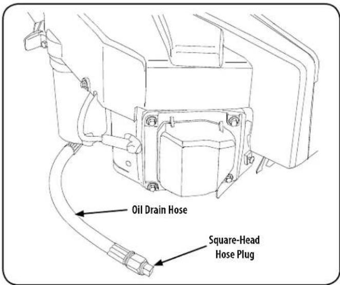
Figure 26
- Route the free end of the oil drain hose toward an appropriate oil collection container with at least a 2.5 quart capacity, to collect the used oil. Remove the oil fill cap/dipstick from the oil fill tube.
- While holding the free end of the oil drain hose over the oil collection container, unscrew the square head hose plug from the end of the hose. See Figure 26. Drain the engine oil into the collection container.
- Route the free end of the oil drain hose toward an appropriate oil collection container with at least a 2.5 quart capacity, to collect the used oil.
- Once the oil has finished draining, replace the square head hose plug and fill the engine as instructed in the engine owner's manual. See engine owner's manual included with this tractor for oil capacity.
SERVICE AND MAINTENANCE
Tire Maintenance
Check the tire air pressure after every 50 hours of operation or weekly. Keep the tires inflated to the recommended pressures. Improper inflation will shorten the tire service life. See the tire side wall for proper inflation pressures. Observe the following guidelines:
- Do not inflate a tire above the maximum pressure shown on the sidewall of the tire.
- Do not reinflate a tire that has been run flat or seriously under inflated. Have a qualified tire mechanic inspect and service the tire.
Lubrication
- Using a pressure lubricating gun, lubricate the front castor wheel axles and the front pivot axle with No. 2 multipurpose lithium grease after every 10 hours of service.
- Periodically lubricate all other pivot points; i.e. the seat pivot bracket, idler pivot bracket on the deck, deck lift shaft assembly, etc. with a quality lubricating oil.
Cleaning and Lubricating the Spindle Pulleys
Once a month remove the belt covers to remove any accumulation of grass clippings from around the spindle pulleys and V-belt. Clean more often when mowing tall, dry grass.
Every 25 hours, lubricate the deck spindles. Locate the spindle lube fitting and using a grease gun, lubricate the spindles. The spindle holds 2.3 ounces of grease. See Figure 27.
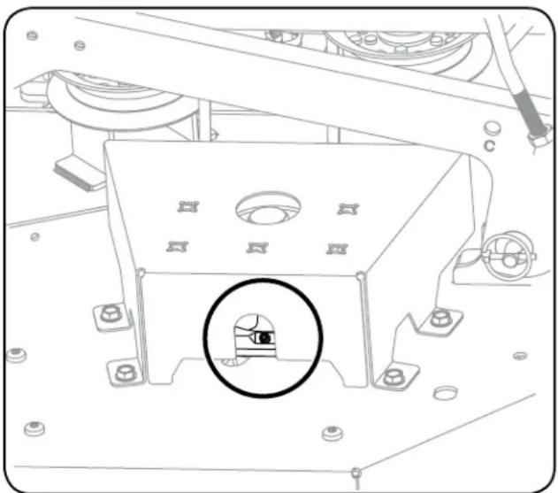
natural_image
Technical line drawing of a mechanical assembly with a circular inset detail (no text or symbols)Figure 27
General Battery Information
WARNING
Should battery acid accidentally splatter into the eyes or onto the skin, rinse the affected area immediately with clean cold water. If there is any further discomfort, seek prompt medical attention. If acid spills on clothing, first dilute it with clean water, then neutralize with a solution of ammonia/water or baking soda/water.
WARNING
NEVER connect (or disconnect) battery charger clips to the battery while the charger is turned on, as it can cause sparks. Keep all sources of ignition (cigarettes, matches, lighters) away from the battery. The gas generated during charging can be combustible. As a further precaution, only charge the battery in a well ventilated area. Always shield eyes and protect skin and clothing when working near batteries.
WARNING
Batteries contain sulfuric acid and may emit explosive gases. Use extreme caution when handling batteries. Keep batteries out of the reach of children.
Battery Maintenance
The battery is filled with battery acid and then sealed at the factory. However, even a "maintenance free" battery requires some maintenance to ensure its proper life cycle.
- Spray the terminals and exposed wire with a battery terminal sealer, or coat the terminals with a thin coat of grease or petroleum jelly, to protect against corrosion.
• Always keep the battery cables and terminals clean and free of corrosion. - Avoid tipping. Even a sealed battery will leak electrolyte when tipped.
Battery Removal
WARNING
Battery posts, terminals and related accessories contain lead and lead compounds. Wash hands after handling.
The battery is located beneath the seat frame. To remove the battery:
SERVICE AND MAINTENANCE
- Remove the hex washer screw securing the battery hold-down bracket to the frame. Then flip the battery hold-down bracket up to free the battery. See Figure 28.
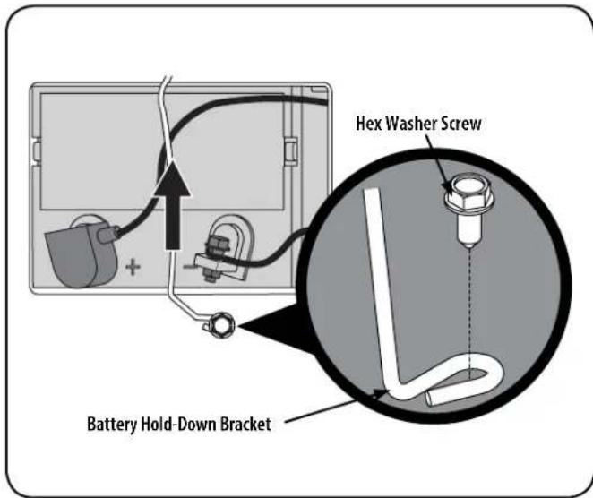
Figure 28
- Remove the hex cap screw and sems nut securing the black negative battery lead to the negative battery post (marked NEG). Move the cable away from the negative battery post.
- Remove the hex cap screw and sems nut securing the red positive battery lead to the positive battery post (marked POS).
- Carefully lift the battery out of the tractor.
- Install the battery by repeating the above steps in the reverse order.
WARNING
Always connect the positive lead to the battery before connecting the negative lead. This will prevent sparking or possible injury from an electrical short caused by contacting the riding mower body with tools being used to connect the cables.
Charging the Battery
- Test and, if necessary, recharge the battery after the riding mower has been stored for a period of time.
- A voltmeter or load tester should read 12.6 volts (DC) or higher across the battery terminals. See Figure 29.
| Voltmeter Reading | State of Charge | Charging Time |
| 12.7 100% Full Charge | ||
| 12.4 75% 90 Min. | ||
| 12.2 50% 180 Min. | ||
| 12.0 25% 280 Min. | ||
Figure 29
- Charge the battery with a 12-volt battery charger at a MAXIMUM rate of 10 amps.
Servicing Electrical System
A fuse is installed to protect the riding mower's electrical system from damage caused by excessive amperage. Always use the same capacity fuse for replacement. If the electrical system does not function, check for a blown fuse. If you have a recurring problem with blown fuses, call 1-888-331-4569 to schedule electrical system service from Sears Parts & Repair.
Relays and Switches
There are several safety switches in the electrical system. If a function of the safety interlock system described earlier is not functioning properly, call 1-888-331-4569 to have the electrical system checked by Sears Parts & Repair.
Hydrostatic Transmission
Your zero turn tractor is equipped with dual integrated hydrostatic pumps/transaxles that are sealed and are maintenance-free. However, this model is equipped with a transmission oil expansion reservoir. Under normal operating conditions, the oil level in the expansion reservoir does not need to be checked and no additional oil is needed. If checking the reservoir oil level, proceed as follows:
WARNING
Check the oil level ONLY before starting the tractor when the transmission oil is fully cooled.
- Pivot the operator's seat forward and clean the reservoir cap and the area around the cap to prevent debris from contaminating the transmission oil. See Figure 30.
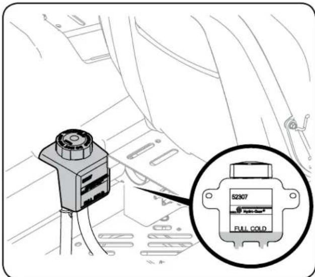
Figure 30
- Turn the reservoir cap counterclockwise to re-move, then check the oil level in the reservoir. Oil should be visible at the bottom of the cup, but the oil level must NOT be above the "FULL COLD" line. See Figure 30. DO NOT FILL THE RESERVOIR.
- If necessary to add oil because of some type of leakage, use a quality 20W50 motor oil and add only enough oil to bring the level to the "FULL COLD" line. Reinstall the cap and fully tighten.
NOTE: Prior to the initial operation of the tractor, the oil level in the reservoir may be slightly higher than the maximum due to air in the oil lines. Operation of the tractor will eventually purge the air from the lines and the oil level will settle to the maximum.
SERVICE AND MAINTENANCE
Adjustments

CAUTION
Shut the engine off, remove the ignition key and engage the parking brake before making adjustments. Protect your hands by using heavy gloves when handling the blades.
Adjusting RH & LH Drive Control Levers
The RH and LH drive control levers can be adjusted up or down and forward or backward for the comfort of the operator. The drive control levers can be placed in either of two height positions, and/or can be moved forward or rearward within the range of the slot in each lower arm.
To adjust the drive control lever height, proceed as follows:
- Remove the upper hex screw and flat washer securing the lever to the pivot bracket.
- While supporting the control lever to keep it from falling, remove the hex screw and flat washer from the bottom of the control lever and lower arm. Refer to Figure 31.
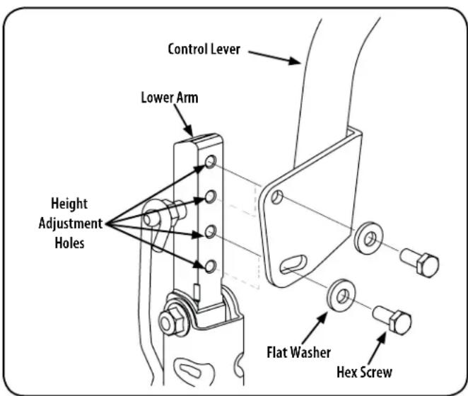
Figure 31
- Reposition the control lever to align with the other set of holes in the lower arm and insert the hex screw through the flat washer and into the lower arm. Tighten the hex screw until snug.
- Insert the hex screw through the flat washer and through the control lever slot and the lower arm. Do not tighten now.
- If you are going to adjust the control levers forward or rearward, proceed to the next step. If not, fully tighten the hex screw.
To adjust the drive control levers forward/rearward, proceed as follows:
- If not already loose, loosen the hex screw and rotate the control lever either forward or rearward to the desired position. See Figure 31. NOTE: If the control lever is too tight to move, slightly loosen the hex screw at the bottom of the control lever.
- Tighten the hex screw to fix the control lever in the adjusted position
- Repeat the above procedure to adjust the other control lever into the same position. Adjust so that both levers are even with each other when in the neutral position.
Deck Leveling
NOTE: Check the tractor's tire pressure before performing any deck leveling adjustments. Refer to Tires for information regarding tire pressure.

WARNING
Shut the engine off, remove the ignition key and engage the parking brake before making adjustments. Protect your hands by using heavy gloves when handling the blades.
Leveling the Deck (Side-to-Side)
NOTE: Check the tractor's tire pressure before performing any deck leveling adjustments. Refer to Tires for information regarding tire pressure. Always level the deck side-to-side before front to rear.
If the cutting deck appears to be mowing unevenly, a side-to-side adjustment can be performed. Adjust if necessary as follows:
- With the tractor parked on a firm, level surface, place the deck lift handle in a middle mowing position and rotate both outside blades so that they are perpendicular with the tractor.
- Measure the distance from the outside of the left blade tip to the ground and the distance from the outside of the right blade tip to the ground. Both measurements taken should be equal. If they're not, proceed to the next step.
- Loosen the lower jam nut on the adjustable lift link attached to the deck lift arm to lower the deck and tighten the upper jam nut to secure the deck in place, loosen the upper jam nut then tighten the lower jam nut to secure the deck in place. See Figure 32.
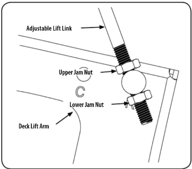
Figure 32
- The deck is properly leveled when both blade tip measurements are equal.
Leveling the Deck (Front-To-Rear)
NOTE: Check the tractor's tire pressure before performing any deck leveling adjustments. Refer to Tires for information regarding tire pressure. Always level the deck side-to-side before front to rear.
The front of the deck should be between 14-38 " lower than the rear of the deck. Adjust if necessary as follows:
- Park the tractor on a firm, level surface and place the deck lift handle in a middle position.
- Rotate the blade nearest the discharge chute so that it is parallel with the tractor.
SERVICE AND MAINTENANCE
- Measure the distance from the front of the blade tip to the ground and the rear of the blade tip to the ground. The first measurement taken should be between 14 " and 38 " less than the second measurement.
- Determine the approximate distance necessary for proper adjustment and proceed, if necessary.
- Using a wrench, raise or lower the front of deck by turning lock nut on the front deck lift rod and secure with the rear jam nuts. See Figure 33.
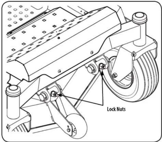
Figure 33
- The deck is properly leveled when the front tip of the blade is 1/4" lower than the rear tip. Retighten the hex bolt on the left rear deck hanger links when proper adjustment is achieved.
Adjusting the Front Gauge Wheels
WARNING
Keep hands and feet away from the discharge opening of the cutting deck.
The front gauge wheels on the mower deck are an anti-scalp feature, and should not ride on the ground. The front gauge wheels should be approximately 14-12 " above the ground when the deck is set in the desired height setting.
Using the deck lift handle, set the deck in the desired height setting, then check the gauge wheel distance from the ground below. If necessary adjust the front gauge wheels as follows:
-
Visually check the distance between the front gauge wheels and the ground. If the gauge wheels are near or touching the ground, they should be raised. If more than 12 " above the ground, they should be lowered.
-
Remove the lock nut securing one of the front gauge wheel hex screws to the deck. Remove the gauge wheel, hex screw and spacer. See Figure 34.
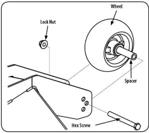
Figure 34
- Insert the hex screw into the one of three index holes in the front gauge wheel bracket that will give the gauge wheel a 1412 " clearance with the ground.
- Note the index hole of the just adjusted wheel, and adjust the other front gauge wheel into the respective index hole of the other front gauge wheel bracket.
Drive Control Lever Stop Adjustment
When the drive control levers are both fully extended forward to the full-speed position and the tractor drifts left or right, the drive control lever stop adjustment can be adjusted to sync the wheel speeds. To perform the adjustment, proceed as follows:
- Identify the side that the tractor is drifting to and adjust the opposite drive control lever. If the tractor drifts right, adjust the left control lever down (decrease speed) and vice versa.
SERVICE AND MAINTENANCE
- Locate the drive control lever stop adjustment bolts on the front of the seat frame. See Figure 35.
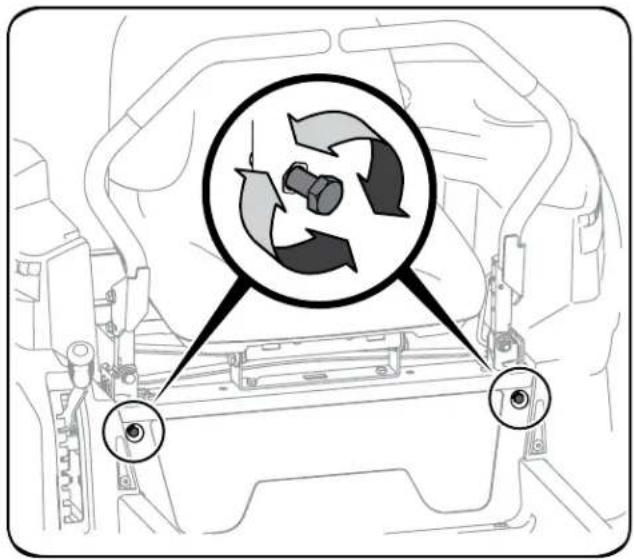
Figure 35
- To decrease the forward speed, turn the bolt clockwise. To increase the forward speed, turn the bolt counter-clockwise. Turn the bolt in the necessary direction 14 -turn at a time. After turning the bolt, check the adjustment by driving the tractor.
- Continue the adjustment until the wheel speeds are in sync and the tractor drives straight with the drive control levers fully extended forward in the full-speed position.
Deck Removal
Remove the mower deck from the tractor as follows:
- Move the tractor to a level surface, disengage the PTO, stop the engine, and set the parking brake.
- Move the deck gauge wheels to their highest setting (lowest deck setting).
- Remove the 'V' belt from the PTO pulley, located on the bottom of the engine, using one of the following two methods.
WARNING
The muffler at the rear of the tractor may be extremely hot, and could cause serious burns. Use extreme caution when near the muffler. Allow the muffler to fully cool before removing the belt from the PTO pulley.
- Releasing Belt Tension with the Idler Pulley
a. Using the deck lift handle, raise the deck to the position that provides the most horizontal run of the belt between the deck idler pulleys and the PTO pulley on the bottom of the engine. See Figure 36.
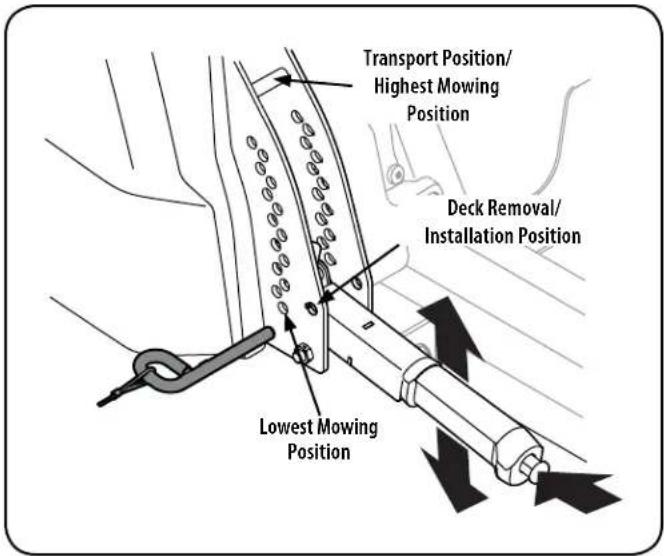
Figure 36
b. Working from the middle of the tractor, pivot the idler bracket and movable idler pulley rearward away from the backside of the "V" belt (a) just far enough to lift the belt up and over the idler pulley (b). See Figure 37.
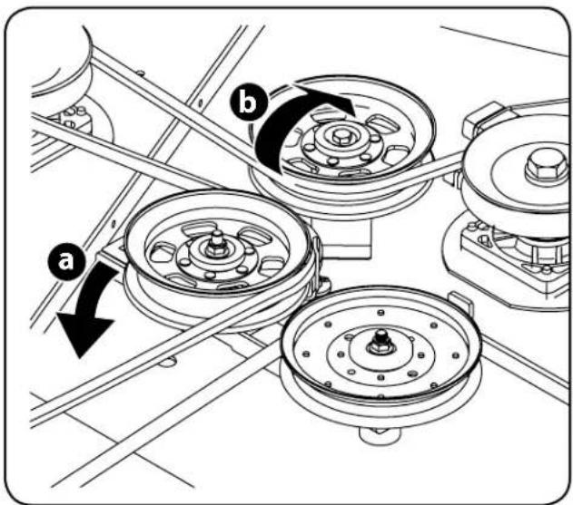
Figure 37
c. From beneath the rear of the tractor, slide the belt off of the PTO pulley on the bottom of the engine.
d. Lower the deck into the deck removal/installation position using the deck lift handle. See Figure 36.
e. Skip ahead to step 6.
SERVICE AND MAINTENANCE
- Rolling the Belt off the PTO Pulley
a. Using the deck lift handle, raise the deck to the position that provides the most horizontal run of the belt between the deck idler pulleys and the PTO pulley on the bottom of the engine.
b. Sitting behind the tractor facing forward, reach beneath the tractor to grasp the belt at the front of the PTO pulley.

WARNING
Use caution to avoid pinching your fingers when rolling the belt off the PTO pulley.
c. Pull the left side of the belt rearward and downward while manually turning the PTO pulley to the right until the belt rides out onto the edge of the lower sheave of the pulley.
NOTE: If pulling the right side of the belt, turn the pulley left.
d. While still holding the belt downward, continue turning the PTO pulley until the belt is rolled off the pulley. Refer to Figure 38.
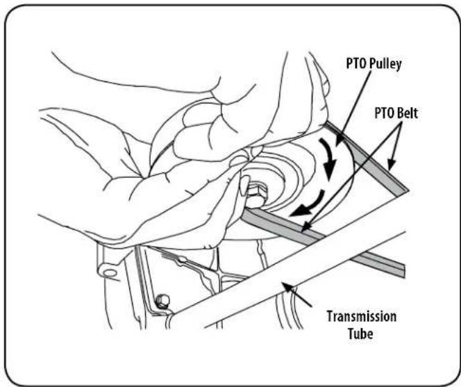
Figure 38
- Locate the LH and RH deck release pins on each side of the deck. Pull the release pins outward and release the deck from the LH and RH deck lift arms. See Figure 39.
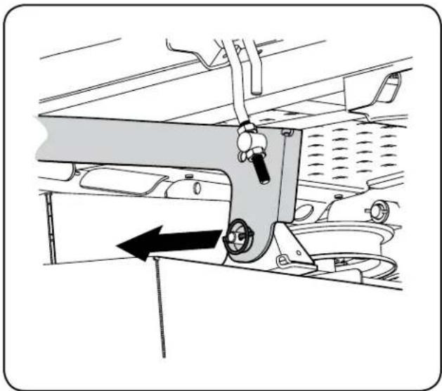
natural_image
Mechanical assembly diagram showing a lever mechanism with no visible text or symbolsFigure 39

CAUTION
There is a certain amount of spring tension due to the weight of the deck. When removing the lift linkage from the deck the tension of the springs will go from the deck to the deck lift handle and snap back.
- Slide the front deck lift rod off the hanger brackets on the front of the deck
- Place the deck lift handle into the highest mowing position and slide the deck out from the right side of the tractor.
Deck Installation
Install the deck on the tractor as follows:
- Place the deck lift handle in the highest mowing position See Figure 36.
- Slide the deck under the tractor on the right side of the tractor lining up the deck hanger brackets and the deck lift arms.
- Once the deck is under the tractor, move the deck lift handle to the deck removal/installation position
NOTE: To line the brackets up properly, it may be necessary to place a small block of wood under each side of the deck.
- Hook the front deck lift rod onto the hanger brackets on the front of the deck.
- Pull the deck release pins outward and maneuver the deck as necessary to align the holes in the deck lift arms with the pins. Refer to Figure 39.
- When aligned, push each pin fully inward through the lift arms to secure the arms in the rear hanger bracket slots.
- Make certain the 'V' belt is in the spindle pulleys on the deck; then route the belt rearward beneath the tractor frame, above the transmission tube(s), to the PTO pulley on the bottom of the engine.
- Using the deck lift handle, raise the deck to the position that provides the most horizontal run of the belt between the deck idler pulleys and the PTO pulley on the bottom of the engine.
SERVICE AND MAINTENANCE
- Make certain the belt is in the spindle pulleys of the deck, and that the backside of the belt is against both the fixed and movable idler pulleys.
- Sitting behind the tractor, facing forward, make certain the belt is not twisted; then reach beneath the tractor to grasp the belt and pull it toward the PTO pulley.
WARNING
Use caution to avoid pinching your fingers when rolling the belt onto the PTO pulley.
- Pull the right side of the belt rearward and place the narrow V side of the belt into the PTO pulley. See Figure 38.
- While holding the belt and pulley together, rotate the pulley to the left (See Figure 38). Continue holding and rotating the pulley and belt until the belt is fully rolled into the PTO pulley.
NOTE: Before using the tractor double-check the belt routing to make sure that the belt has been routed properly.
Replacing the Belt
- Remove the deck from beneath the tractor, (refer to Deck Removal).
- Remove the hex washer screws securing the belt covers to the deck. See Figure 40.
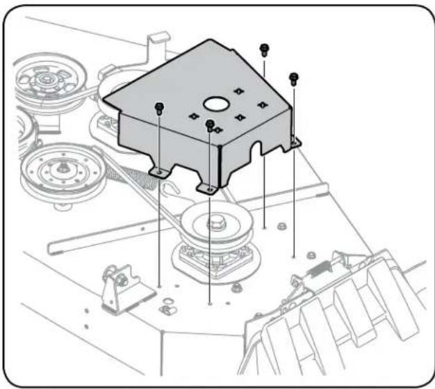
natural_image
Technical line drawing of a mechanical assembly with a central component and surrounding components (no text or symbols)Figure 40
- Remove the two idler pulleys by removing the hex screws, washers and flange lock nuts that secure them to the deck and the idler arm. See Figure 41. Do not lose any of the hardware when removing the hex screw and flange lock nut.
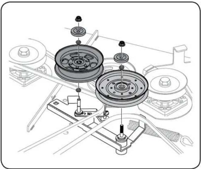
natural_image
Technical line drawing of a mechanical assembly with multiple circular components and mounting brackets (no text or symbols)Figure 41
NOTE: Take note of the position of the belt guards to ensure they are properly re-installed.
- Remove the belt from the spindle pulleys.
- Install the new belt around the spindle pulleys as shown and reinstall the belt covers. See Figure 40.
- Place the belt around the idler pulleys removed in step 3 with the "V" side facing in. Once in place, reinstall all the hardware and tighten the flange lock nut to secure the assembly. See Figure 42.
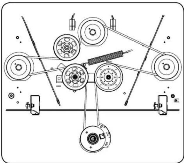
natural_image
Technical line drawing of a mechanical assembly with pulleys, gears, and tools (no text or symbols)Figure 42
- Route the belt as shown in Figure 42 and then reinstall the deck (refer to Deck Installation).
SERVICE AND MAINTENANCE
Mower Blade Care
WARNING
Before performing any maintenance, place the PTO switch in the "OFF" position, engage the parking brake lever, turn the ignition key to the "OFF" position and remove the key from the switch. Protect your hands by using heavy gloves when handling the blades. When servicing the mower deck, be careful not to cut yourself on the sharpened blades.
The cutting blades must be kept sharp at all times. Sharpen the cutting edges of the blades evenly so that the blades remain balanced and the same angle of sharpness is maintained.
If the cutting edge of a blade has already been sharpened many times, or if any metal separation is present, it is recommended that new blades be installed. New blades may be obtained through Sears Parts & Repair or by calling 1-888-331-4569.
The blades may be removed as follows.
- Remove the deck from beneath the riding mower, (refer to Deck Removal) then gently flip the deck over to expose its underside.
- Use a 1- 18 " wrench to hold the hex nut on top of the spindle assembly when loosening the hex nut securing the blade. A block of wood may be placed between the deck housing and the cutting edge of the blade to help in breaking loose the hex nut securing the blade. See Figure 43.
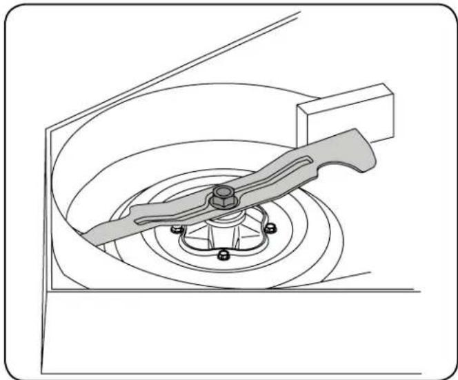
natural_image
Technical line drawing of a mechanical assembly with a lever and base mount (no text or symbols)Figure 43
- When reinstalling the blades, be sure they are installed so that the wind wings are pointing upward toward the top of deck.
- Use a torque wrench to tighten the blade nuts to 70-90 ft-lbs.
- Reinstall the deck (refer to Deck Installation).
Transmission Drive Belt
Several components must be removed and special tools used in order to change the riding mower's transmission drive belt. See your Sears Service Center or to schedule service, simply contact Sears at 1-888-331-4569.
Tractor Creeping
Creeping is the slight forward or backward movement of the mower when the throttle is on and the speed control levers are in the neutral position. If your mower creeps, see an authorized service dealer.
OFF-SEASON STORAGE
WARNING
Never store garden riding mower with fuel in tank indoors or in poorly ventilated areas where fuel fumes may reach an open flame, spark, or pilot light as on a furnace, water heater, clothes dryer, or gas appliance.
Riding Mower Storage
If your riding mower is not going to be operated for an extended period of time (thirty days to approximately six months), the riding mower should be prepared for storage. Store the riding mower in a dry and protected location. If stored outside, cover the riding mower (including the tires) to protect it from the elements. The procedures outlined below should be performed whenever the riding mower is placed in storage.
- Change the engine oil and filter following the instructions provided in the Service and Maintenance section of this manual.
WARNING
Never store the riding mower with fuel in the tank indoors or in poorly ventilated enclosures, where fuel fumes may reach an open flame, spark or pilot light as on a furnace, water heater, clothes dryer, etc.
- If storing the riding mower for 30 days or more:
a. To prevent gum deposits from forming inside the engine's carburetor and causing possible malfunction of the engine, the fuel system must be either completely emptied, or the gasoline must be treated with a stabilizer to prevent deterioration.
WARNING
Fuel left in the fuel tank deteriorates and will cause serious starting problems.
b. Using a fuel stabilizer:
- Read the product manufacturer's instructions and recommendations.
- Add to clean, fresh gasoline the correct amount of stabilizer for the capacity (approximately 3 gallons) of the fuel system.
- Fill the fuel tank with treated fuel and run the engine for 2-3 minutes to get stabilized fuel into the carburetor.
c. Emptying the fuel system:
- Prior to putting the riding mower in storage, monitor fuel consumption with the goal of running the fuel tank empty.
- Start the engine and allow it to run out of fuel. This will prevent gum and varnish deposits from forming.
- Remove the spark plugs and pour approximately one ounce of oil into each cylinder. Crank the engine one or two turns to spread the oil evenly on the cylinder walls. Replace the spark plugs.
- Clean the engine and the entire riding mower thoroughly.
NOTE: Use of a pressure washer or garden hose is not recommended to clean your riding mower. They may cause damage to electrical components, spindles, pulleys, bearings or the engine. The use of water will result in shortened life and reduce serviceability.
- Sharpen the blades so that the mower will be ready to use when needed.
- Protect the metal surfaces. Repair scratches with the appropriate touch-up spray paint. Brush a rust preventive oil on any unpainted surfaces including the pulleys and blades. (Be careful not to get any oil on the drive belts.)
- Clean and fully charge the battery, then disconnect the negative cable at the battery to prevent possible discharge. Recharge the battery periodically when in storage.
NOTE: Remove the battery if exposed to prolonged periods of sub-freezing temperatures. Store in a cool, dry location where temperatures are above freezing.
- Lubricate all lubrication points.
- Jack the mower up and store it on blocks to take the weight off of the tires.
Removing the Riding Mower from Storage
- Check the engine oil.
- Fully charge the battery, lower riding mower off blocks, and inflate the tires to the recommended pressure.
- Remove the spark plugs and wipe them off. Using the starter, crank the engine to pump the excess oil out of the spark plug holes. Replace the spark plugs and the ignition leads.
- If drained before storing, fill the fuel tank with clean, fresh gasoline.
- Check the level of the engine oil in the crankcase and the hydraulic reservoir tank.
- Start the engine and allow to idle for a few minutes to ensure engine is operating properly.
- Drive the riding mower without a load to make certain all the riding mower systems are functioning properly.
TROUBLESHOOTING
WARNING
Before performing any type of maintenance/service, disengage all controls and stop the engine. Wait until all moving parts have come to a complete stop. Disconnect spark plug wire and ground it against the engine to prevent unintended starting. Always wear safety glasses during operation or while performing any adjustments or repairs.
This section addresses minor service issues. To locate the nearest Sears Service Center or to schedule service, simply contact Sears at 1-888-331-4569.
Problem Cause Remedy
| Engine Fails to start 1. PTO/Blade Engage knob engaged.2. Parking brake not engaged.3. Spark plug wire disconnected.4. Throttle control lever not in correct starting position.5. Fuel tank empty, or stale fuel.6. Blocked fuel line or fuel filter.7. Faulty spark plug.8. Engine flooded.9. Fuse(s) blown. | 1. Place knob in disengaged (OFF) position.2. Engage parking brake.3. Connect wire to spark plug.4. Place Throttle lever to FAST position.5. Fill tank with clean, fresh (less than 30 days old) gas.6. Replace fuel line. See a Sears or other qualified service dealer. Replace fuel filter. See the Service and Maintenance section.7. Clean, adjust gap or replace plug.8. Crank engine with throttle in FAST position.9. Replace fuse. |
| Engine runs erratically | 1. Riding mower running with Choke activated.2. Spark plug wire loose.3. Blocked fuel line or stale fuel.4. Vent in gas cap plugged.5. Water or dirt in fuel system.6. Dirty air cleaner. |
TROUBLESHOOTING
Problem Cause Remedy
| Engine overheats 1. Engine oil level low2. Air flow restricted | 1. Fill engine with proper amount and type of oil.2. Clean grass clippings and debris from around the engine's cooling fins and blower housing. |
| Engine hesitates at high RPMs | 1. Spark plug gap set too close |
| Engine idles poorly 1. Fouled spark plug2. Dirty air cleaner | 1. Replace spark plug and adjust gap.2. Clean or replace air cleaner element and/or clean pre-cleaner. |
| Excessive vibration 1. Cutting blades loose or unbalanced2. Damaged, dull, or bent cutting blade | 1. Tighten blade and spindle. Balance blade.2. Replace blade. |
| Uneven cut 1. Deck not leveled properly.2. Dull blade.3. Uneven tire pressure. | 1. Perform side-to-side deck adjustment.2. Sharpen or replace blade.3. Check tire pressure in all four tires. |
Manual del Operador
CRAFTSMAN®
PRO SERIES
PRO L SERIE
TRACTOR CON RADIO DE GIRO CERO
AVEC INTELLIGENT TECHNOLOGIE CORTACÉSPED


Modelo N.° 247.20420*, 247.20422* & 247.20424*
Warranty/Service......See Separate Supplement
natural_image
Line drawing of a battery with attached components and wiring (no text or symbols)Figura 5
natural_image
Technical line drawing of a mechanical assembly with bolts and components (no text or symbols)Figura 6
natural_image
Technical illustration of a mechanical device with internal components and directional arrows indicating movement (no text or symbols)Figura 8

PRECAUCIÓN
natural_image
Mechanical assembly diagram showing a lever mechanism with directional arrows indicating motion (no text or symbols)Figura 20
natural_image
Technical line drawing of a mechanical assembly with gears and shafts (no text or symbols)Figure 24
natural_image
Technical line drawing of a mechanical component with a circular inset showing a detail (no text or symbols)Figura 27
Figura 35
Figura 37
natural_image
Technical diagram of a mechanical assembly with directional arrow indicating motion (no text or symbols)Figura 39

PRECAUCIÓN
natural_image
Technical line drawing of a mechanical assembly with a central component and surrounding components (no text or symbols)Figura 40
natural_image
Technical line drawing of a mechanical assembly with multiple components and no visible text or symbolsFigura 41
natural_image
Technical line drawing of a mechanical assembly with pulleys, gears, and tools (no text or labels)Figura 42
natural_image
Technical line drawing of a mechanical assembly with a lever and base mount (no text or symbols)Figura 43
- WITH SMART LAWN TECHNOLOGY
- CAUTION
- SAFETY INSTRUCTIONS
- WARNING
- CALIFORNIA PROPOSITION 65
- ! DANGER
- SAVE THESE INSTRUCTIONS!
- GENERAL OPERATION
- SLOPE OPERATION
- Do:
- Do Not:
- CHILDREN
- TOWING
- SERVICE
- Safe Handling of Gasoline:
- General Service
- DO NOT MODIFY ENGINE
- NOTICE REGARDING EMISSIONS
- SPARK ARRESTOR
- SAFETY SYMBOLS
- SLOPE GAUGE
- dashed line
- USE THIS SLOPE GAUGE TO DETERMINE
- IF A SLOPE IS TOO STEEP FOR SAFE OPERATION!
- ASSEMBLY
- Set-Up
- Moving The Riding Mower Manually
- Install Operator's Seat
- Position Drive Control levers
- Connecting the Battery Cables
- Lower Deck Discharge Chute Deflector
- Checking Tire Pressure
- Adjusting the Gauge Wheels
- Adjusting the Seat
- Gas and Oil
- Fuel Recommendations
- Adding Fuel
- Checking and Adding Oil
- Smart Lawn App Bluetooth® Activation
- OPERATION
- RH and LH Drive Control Levers
- Cup Holder
- Throttle Control
- Choke Control
- Ignition Switch Module
- Deck Height Index
- Deck Lift Handle
- Power Take-Off (PTO) Knob
- Transmission Bypass Rods
- Fuel Tank Cap
- Fuel Level Window
- Transmission Oil Expansion Reservoir
- LCD Service Minder & Hour Meter w/ Smart Lawn App Bluetooth® Activation
- Smart Lawn App
- Change Oil
- Low Oil (If so equipped)
- Low Battery
- Air Filter Service
- General Safety
- Checking the Safety Interlock Circuits
- Before Operating Your Tractor
- Safety Interlock System
- Starting the Engine
- Cold Weather Starting
- Using Jumper Cables To Start Engine
- Stopping the Engine
- Practice Operation (Initial Use)
- Driving the Tractor
- Driving the Tractor Forward
- Turning the Tractor While Driving Forward
- Driving the Tractor In Reverse
- Turning While Driving Rearward
- Reverse Caution Mode
- Executing a Zero Turn
- Executing a "Y" Maneuver
- Stopping the Tractor
- Driving On Slopes
- Operating The PTO
- Mowing
- Deck Lift Lever
- SERVICE AND MAINTENANCE
- MAINTENANCE SCHEDULE
- Post-Operation Tractor Care
- Cleaning the Underside of the Deck
- Deck Wash System
- Cleaning the Tractor
- Storing the Tractor
- Engine Maintenance
- Changing the Engine Oil
- Tire Maintenance
- Lubrication
- Cleaning and Lubricating the Spindle Pulleys
- General Battery Information
- Battery Maintenance
- Battery Removal
- Charging the Battery
- Servicing Electrical System
- Relays and Switches
- Hydrostatic Transmission
- Adjustments
- Adjusting RH & LH Drive Control Levers
- Deck Leveling
- Leveling the Deck (Side-to-Side)
- Leveling the Deck (Front-To-Rear)
- Adjusting the Front Gauge Wheels
- Keep hands and feet away from the discharge opening of the cutting deck.
- Drive Control Lever Stop Adjustment
- Deck Removal
- Deck Installation
- Replacing the Belt
- Mower Blade Care
- Transmission Drive Belt
- Tractor Creeping
- OFF-SEASON STORAGE
- Riding Mower Storage
- Removing the Riding Mower from Storage
- TROUBLESHOOTING
- Manual del Operador
- CRAFTSMAN®
- PRO SERIES
- PRO L SERIE
- TRACTOR CON RADIO DE GIRO CERO
- PRECAUCIÓN
Brand : Craftsman
Model : 27052
Category : Lawn mower