
Weldforce 155M - Soldering iron Weldclass - Free user manual and instructions
Find the device manual for free Weldforce 155M Weldclass in PDF.


| Brand | Weldclass |
| Model | Weldforce 155M |
| Product Type | Soldering iron (MIG/MMA/TIG welding machine) |
| Dimensions (L x W x H) | 450 x 235 x 370 mm |
| Weight | 9.3 kg |
| Power Supply | 230V +/- 15% 50Hz Single Phase |
| Rated Input Current (I_eff) | 9 A |
| Maximum Input Current (I_max) | 18 A |
| Factory Fitted Plug Rating | 10 A |
| Protection Class | IP23 |
| Standard | AS 60974.1 |
| MIG Welding Current Output | 20 – 115 A (max 150 A) |
| MIG Welding Voltage Output | 15 – 19.8 V |
| MIG Duty Cycle | 115 A @ 20%, 65 A @ 60%, 50 A @ 100% |
| Nominal Open Circuit Voltage | 44 V |
| MIG Wire Sizes | 0.6, 0.8, 0.9 mm |
| Spool Size | 100 mm (1 kg) & 200 mm (4.5–5 kg) |
| Stick (MMA) Welding | Not available on this model (Weldforce 175MST only) |
| TIG Welding | Not available on this model (Weldforce 175MST only) |
| Control Panel Features | Power On LED, Thermal Overload Indicator, Output Knob, Inductance Knob |
| Cooling | Fan-cooled with thermal overload protection |
| Maintenance | Regular cleaning of ventilation slots and casing; check cables and consumables before use |
| Safety Features | Thermal protection, power supply voltage protection, short circuit protection |
| Warranty Registration | Register within 30 days for extended warranty at www.weldclass.com.au/weldforcewarranty |
Frequently Asked Questions - Weldforce 155M Weldclass
User questions about Weldforce 155M Weldclass
0 question about this device. Answer the ones you know or ask your own.
Ask a new question about this device
Download the instructions for your Soldering iron in PDF format for free! Find your manual Weldforce 155M - Weldclass and take your electronic device back in hand. On this page are published all the documents necessary for the use of your device. Weldforce 155M by Weldclass.
USER MANUAL Weldforce 155M Weldclass
natural_image
Abstract black and white geometric pattern with radial lines and a central star (no text or symbols)Weldclass
Be Outstanding
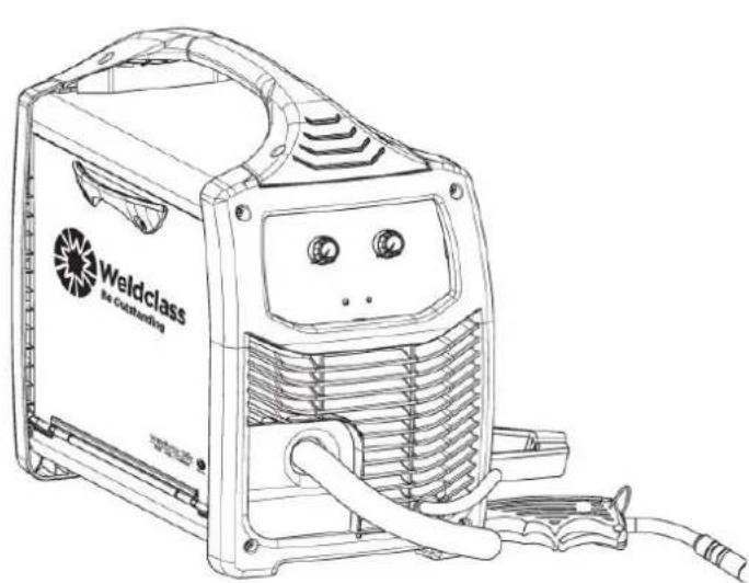
Weldforce 155M Weldforce 175MST
natural_image
Line drawing of a Weldclass 8x40 welding machine with visible heat exchangers and wiring (no text or symbols on the device itself)
OPERATING INSTRUCTIONS
Edition 2.6
IMPORTANT!
To qualify for extended warranty, you must register within 30 days of purchase. See inside for details.
Read these Operating Instructions Completely before attempting to use this machine. Save this manual and keep it handy for quick reference. Pay particular attention to the safety instructions we have provided for your protection. Contact your distributor if you do not fully understand anything in this manual.
Congratulations & thank you for choosing Weldclass!
The Weldforce range from Weldclass provides market leading value, features and durability.
Register Your Warranty Now
To qualify for an extended warranty, you must register within 30 days of purchase.
Full details on warranty period and terms can be found at www.weldclass.com.au/WarrantyInfo
Please register your warranty now by going to:

www.weldclass.com.au/weldforcewarranty
You will need;
a) A copy of your purchase invoice / receipt.
b) Your machine serial number which can be found on the technical data plate on the back of the machine, or on the outside of the box that your machine came in.
Satisfaction Guarantee
For full details on our satisfaction guarantee, refer to www.weldclass.com.au/mbg
Using Gasless MIG Wire?
Weldclass Platinum GL-11 is Australia's No.1 Gasless wire. Welders right across Australia & beyond rate Platinum GL-11 as the most user-friendly, smoothest running gasless wire on the market.
Talk to your Weldclass distributor today, or go to: www.Weldclass.com.au/GL-11
natural_image
Close-up of a metallic wire spool with visible blades and central hub (no text or symbols)Platinum GL-11
1 CONTENTS
1 CONTENTS....3
2 BASIC SPECIFICATIONS....7
3 KNOW YOUR MACHINE....8
3.1 Machine Front 8
3.2 Machine Rear 8
3.3 Control Panel....9
3.4 Symbols chart....10
4 CONTROLS EXPLAINED....11
4.1 Weld Process Selection (Weldforce 175MST only)....11
4.1.1 MIG/MAG Process:....11
4.1.2 MMA (Stick) Process: 11
4.1.3 TIG Process:....11
4.2 Welding Power Output Control....11
4.3 Inductance Control (MIG/MAG only)....12
4.4 Arc Force Adjustment (MMA/Stick only) (Weldforce 175MST only)....12
4.5 Error/Over Temperature Indicator Light 13
5 POWER SUPPLY 13
5.1 Electrical Connection....13
5.2 Extension Leads....13
5.3 Generator Use....13
5.3.1 Generator Size....13
5.3.2 Generator Quality & Warranty Limitations....14
5.3.3 3 Golden Rules of Generator use....14
6 OPERATING ENVIRONMENT....14
6.1 Location....14
6.2 Ventilation....14
7 BASIC OPERATION....15
7.1 MIG Welding....15
7.1.1 Fitting Wire Spool....15
7.1.2 Loading Wire Feeder....16
7.1.3 Gasless Welding Setup....18
7.1.4 Gas MIG Welding Setup 19
7.1.5 Additional Setup for MIG welding with Aluminium (Weldforce 175MST only)....20
7.1.6 Settings for MIG Welding....20
7.1.1 Drive Rollers & Torch Liners for different Wires....21
7.2 Stick (MMA) Welding Operation (Weldforce 175MST only)....22
7.3 Lift TIG Operation (Weldforce 175MST only)....23
8 ACCESSORIES, SPARE PARTS & CIRCUIT DIAGRAMS....24
8.1 MIG Torch and Spares for Weldforce 155M:....24
8.2 MIG Torch and Spares for Weldforce 175M:....25
8.3 TIG Torch and Spares (Optional Extra for Weldforce 175MST only):......26
8.4 Optional Accessories....27
8.5 Drive Rollers 27
8.6 Machine Spare Parts: 28
8.7 Primary Schematic Circuit Diagram....31
9 CARE & MAINTENANCE....32
9.1 Keep your Welding Machine in Top Condition....32
9.2 Storing the Welder 32
10 GENERAL GUIDE TO WELDING 33
10.1 Duty Cycle Rating 33
10.2 Choosing a Welding Process – MIG, Stick or TIG? 33
10.2.1 The Stick (MMA) Process ....33
10.2.2 The TIG Process....34
10.2.3 The MIG Process 34
10.3 Joint Preparations ....35
11 MIG BASIC WELDING GUIDE....37
11.1 MIG Basic Welding Techniques ....37
11.2 Gas Metal Arc Welding (GMAW)....37
11.3 Flux Cored Arc Welding (FCAW) 37
11.4 Position of MIG Torch....38
11.5 Distance from the MIG Torch Nozzle to the Work Piece....38
11.6 Travel Speed 38
11.7 MIG Welding (GMAW) Variables....39
11.7.1 Preselected Variables....39
11.7.2 Primary Adjustable Variables....39
11.7.3 Secondary Adjustable Variables....39
11.8 Establishing the Arc and Making Weld Beads 41
11.9 MIG Output Settings 41
11.9.1 Changing to a different welding wire....41
11.10 Welding wire Size Selection 41
11.11 MIG Welding Troubleshooting 42
11.11.1 Porosity Problems....42
11.11.2 Wire Feed Problems....43
11.11.3 Weld Quality Problems 44
12 STICK (MMA) BASIC WELDING GUIDE 46
12.1 Size of Electrodes 46
12.2 Storage of Electrodes 46
12.3 Electrode Polarity....46
12.4 Effects of Stick (MMA) Welding on Various Materials....46
12.4.1 High Tensile and Alloy Steels....46
12.4.2 Manganese Steels 46
12.4.3 Cast Iron 46
12.5 Types of Electrodes 47
12.5.1 MILD STEEL: 47
12.5.2 CAST IRON: 47
12.5.3 STAINLESS STEEL: 47
12.6 Suggested Settings for Typical Stick (MMA) Applications ....47
12.7 MMA Welding Techniques 48
12.7.1 A Word for Beginners....48
12.7.2 The Welder....48
12.7.3 Striking the Arc....48
12.7.4 Arc Length....49
12.7.5 Rate of Travel 49
12.8 Making Welded Joints....50
12.8.1 Butt Welds....50
12.8.2 Fillet Welds....51
12.8.3 Vertical Welds 52
12.8.4 Overhead Welds....53
12.9 MMA (Stick) Troubleshooting ....54
13 TIG BASIC WELDING GUIDE....56
13.1 TIG Electrode Selection and Preparation ....56
13.1.1 Electrode Polarity....56
13.1.2 Preparing Tungsten for DC Electrode Negative (DCEN) Welding 57
13.1.3 Shielding Gas for TIG Welding....58
13.1.4 Typical TIG Welding Settings....58
13.2 TIG Welding Troubleshooting....59
14 KNOWLEDGE & RESOURCES....60
15 SAFETY....60
15.1 Store and Retain this Manual....60
15.2 Important Safety Information ....60
15.3 Welding Operation....60
15.4 Welding Safety Instructions & Warnings....62
15.4.1 Personal Safety....63
15.4.2 Arc Rays can Burn Eyes and Skin....63
15.4.3 Noise Can Damage Hearing 63
15.4.4 Work Environment Safety 64
15.4.5 Electricity Can Kill....64
15.4.6 Fumes And Gases....65
15.4.7 Fire & Explosive Risks....66
15.4.8 Sparks & Hot Metal....66
15.4.9 Gas Cylinders....67
16 WARRANTY....67
16.1 Warranty Information 67
2 BASIC SPECIFICATIONS
| Description | Weldforce 155M | Weldforce 175MST |
| Part Number | WC-155M | WC-175MST |
| Dimensions of Power Source (L x W x H) | 450 x 235 x 370mm | 450 x 235 x 370mm |
| Weight of Power Source | 9.3kg | 11kg |
| Standard | AS 60974.1 | AS 60974.1 |
| Power Supply | 230V +/- 15% 50hz Single Phase | |
| Factory Fitting Supply Plug Rating | 10A | 10A |
| Effective Input Current ( I_eff ) | 9A | 10A |
| Maximum Input Current ( I_max ) | 18A | 22A |
| Protection Class | IP23 | IP23 |
| MIG Welding | ||
| Welding Current Output | 20 – 115A (max 150A) | 20 – 140A (max 170A) |
| Welding Voltage Output | 15 – 19.8V | 15 – 21V |
| Duty Cycle | 115A / 19.8V @ 20%65A / 17.3V @ 60%50A / 16.5V @ 100% | 140A / 21V @ 20%80A / 18V @ 60%60A / 17V @ 100% |
| Nominal Open Circuit Voltage | 44V | 44V |
| Spool Size | 100mm (1kg) & 200mm (4.5kg or 5kg) | |
| MIG Wire Sizes | 0.6, 0.8, 0.9mm | 0.6, 0.8, 0.9, 1.0mm |
| Stick (MMA) Welding | ||
| Welding Current Output | N/A | 20 – 120A (max 150A) |
| Duty Cycle | 120A / 24.8V @ 30%80A / 23.2V @ 60%60A / 22.4V @ 100% | |
| Nominal Open Circuit Voltage | 44V | |
| MMA Electrode Size | 1.6 – 3.2mm | |
| TIG Welding | ||
| Welding Current Output | N/A | 20 – 120A (max 150A) |
| Duty Cycle | 120A / 14.8V @ 30%80A / 13.2V @ 60%60A / 12.4V @ 100% | |
| Nominal Open Circuit Voltage | 44V | |
| TIG Tungsten Size | 1.6 – 2.4mm | |
Table 1
For full machine specifications, refer to technical data plate on back of machine – or go to:
http://www.weldclass.com.au/155M / www.Weldclass.com.au/170MST
3 KNOW YOUR MACHINE
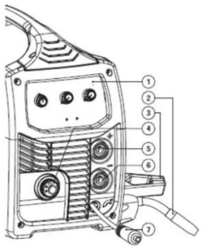
3.1 Machine Front
- Control panel
- MIG Torch
- Earth Lead
- Euro MIG Torch Connection
- Positive Dinse Socket
- Negative Dinse Socket
- Torch Polarity Change Tail

Weldforce 155M
Figure 1
Weldforce 175MST
3.2 Machine Rear
- Mains Power Switch
- Gas Inlet Connection
- 240V AC Mains Power Input Lead

Figure 2
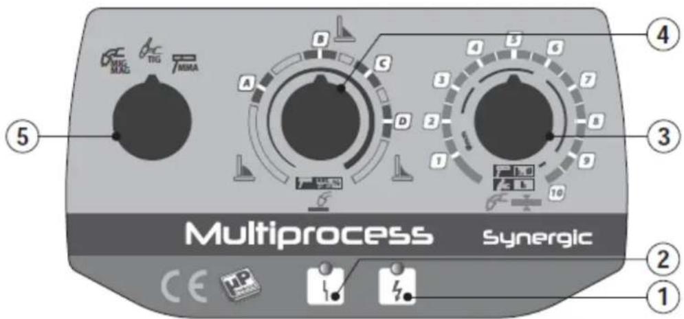
3.3 Control Panel
- Power Indicator LED
- Thermal Overload / Error Indicator LED
- Output Knob
- Inductance (/Arc Force) Knob
- Process Selector Knob

Weldforce 155M
Weldforce 170M
Figure 3
3.4 Symbols chart
| 1 | Power On |
| 0 | Power Off |
| Power OnIndication | |
| Fault Indication | |
| Caution / Hazard | |
| Read InstructionManual | |
| MaterialThickness | |
| Wire Feed | |
| MIG Inductance | |
| 1~ | Single phaseInverter powersource DC |
| MIG (GMAW)Function | |
| Stick/MMA(SMAW) Function | |
| TIG (GTAW)Function | |
| Power SupplyConnection | |
| 1~ | Single Phase |
 | Direct Current (DC) | |
 | Negative | |
 | Positive | |
 | Hertz (cycles/sec) | |
 | Duty Cycle | |
 | Amperage (Current) | |
 | Voltage | |
 | Electrical Hazard | |
 | Toxic Gas/Fume Hazard | |
 | Explosive Hazard | |
 | Eye Injury Hazard | |
 | Pacemaker Interference Warning | |
 | Do not suspend from handle | |
 | Radiation Hazard | |
Table 2
4 CONTROLS EXPLAINED
4.1 Weld Process Selection (Weldforce 175MST only)
- Rotate 'Process Selector Knob' (5) to desired position.
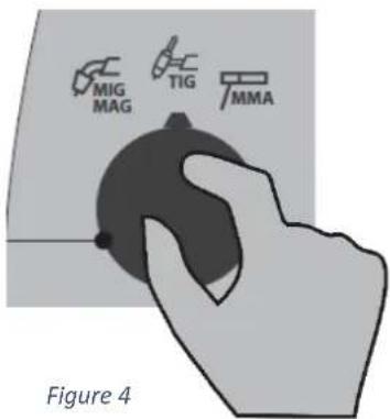
4.1.1 MIG/MAG Process:
In this mode the Inductance Knob adjusts inductance (arc focus) and the Output Knob adjusts target output (power).
4.1.2 MMA (Stick) Process:
In this mode the Inductance Knob adjusts arc force and the Output Knob adjusts target amperage output.
4.1.3 TIG Process:
In this mode the Inductance Knob is disabled and the Output Knob adjusts target amperage output.
4.2 Welding Power Output Control
This output power of the weld is controlled by the Output Knob.
In MIG/MAG process mode the wirespeed and voltage of the arc are both adjusted together as this is a Synergic technology machine.
In MMA (Stick) & TIG process modes (Weldforce 175MST only) this Output Knob adjusts the amperage output.

4.3 Inductance Control (MIG/MAG only)
This setting changes the MIG waveform to simulate changing the inductance of the welding circuit. Inductance controls the rate of the current rise and fall as the welding wire contacts the workpiece (known as a short circuit).
More inductance increases the short circuit time and decreases the short circuit frequency rate. This causes a wider and more penetrating arc, often with better edge wetting, useful for thicker weld joints.
Less inductance will create a narrow more focused arc. This effect can also be used to fine tune the arc to produce less spatter. This is often effective on thin materials.
Wire speed, wire size and type, shielding gas will all change the effect that the inductance setting has on the welding arc.
To adjust inductance, rotate the Inductance Knob.

Figure 5
4.4 Arc Force Adjustment (MMA/Stick only) (Weldforce 175MST only)
Arc Force setting is adjustable from 0 – 100%. Sometimes called 'Dig' or 'Arc Control'. A Stick welder is designed to produce constant output current (CC). This means with different types of electrode and arc length; the welding voltage varies to keep the current constant. This can cause instability in some welding conditions as Stick welding electrodes will have a minimum voltage they can operate with and still have a stable arc.
Arc Force control boosts the welding power if its senses the welding voltage is getting too low. The higher the arc force adjustment, the higher the minimum voltage that the power source will allow. This effect will also cause the welding current to increase. 0 is Arc Force off, 100% is maximum Arc Force. This is practically useful for electrode types that have a higher operating voltage requirement or joint types that require a short arc length such as out of position welds.
4.5 Error/Over Temperature Indicator Light
Error/Over Temperature Indicator Light illuminates yellow to indicate that welding current has stopped for one of the following reasons:
- Thermal Protection: when duty cycle is exceeded and thermal protection is activated. When thermal protection is activated, welding output will be disabled until machines cools sufficiently and overload indicator lamp goes out.
- Power Supply Voltage Protection: the machine will stop functioning if the input power supply voltage exceeds unsafe limits (over 15%).
- Short Circuit Protection: automatically shuts down the welding machine if there is short circuit in the welding circuit (e.g. torch touch the job or stick electrode sticks to the job).
This may also activate if there are electronic circuit failure issues.

Figure 6
5 POWER SUPPLY
5.1 Electrical Connection
The Weldforce 155M & 175MST machines are designed to operate on a 10A 240V AC power supply.
5.2 Extension Leads
If an extension cord must be used, it should be minimum cable core size 2.0mm^2 for length of up to 10m, or minimum 2.5mm^2 for lengths over 10m.
Using extension leads of over 50m is not recommended.
5.3 Generator Use
This machine is designed with generator use in mind and incorporates wide voltage tolerance and intelligent voltage sensing technology to provide maximum protection from power fluctuations that can occur with motor generators.
5.3.1 Generator Size
Generator size should be not less than 7kva. A 7kVa generator may not provide enough power to enable full output and duty of this welder. However, it should provide sufficient power to enable the majority of applications for which this machine was designed.
To enable full output and duty cycle of this welder a minimum recommended generator size is minimum 10kVa.
5.3.2 Generator Quality & Warranty Limitations
Avoid using poor, low quality generators as these have the greatest risk of power spikes etc. A suitable quality generator should have a THD (total harmonic distortion) rating of no more than 6%. Most reputable generator suppliers will be able to specify the THD ratings on their product.
Any damage caused by poor quality generator power supply or incorrect use is not covered under warranty.
5.3.3 3 Golden Rules of Generator use
When running an inverter welder off a generator there are 3 VERY IMPORTANT Golden Rules that MUST be followed:
- Do NOT plug welder into generator until AFTER generator has been started up and is running smoothly
- UNPLUG welder from generator BEFORE shutting generator down/turning generator off
- NEVER let your generator run out of fuel whilst the welder is plugged in.
Following these Golden Rules will significantly reduce the risk of any damage resulting from generator power supply.
6 OPERATING ENVIRONMENT
6.1 Location
The machine has electrical components and control circuit boards which may be damaged by excessive moisture, dust and dirt, so a clean and dry operating environment is important for reliable product life.
The enclosure design of this power source meets the requirements of IP23S as outlined in AS60529. This provides adequate protection against solid objects (greater than 12mm), and direct protection from vertical drops. Under no circumstances should the unit be operated or connected in a micro environment that will exceed the stated conditions. For further information please refer to AS 60529.
6.2 Ventilation
Adequate ventilation is required to provide proper cooling for the machine. Ensure that the machine is placed on a stable level surface where clean cool air can easily flow through the unit.
7 BASIC OPERATION
7.1 MIG Welding
WARNING! Before changing the feed roller or wire spool, ensure that the mains power is switched off.
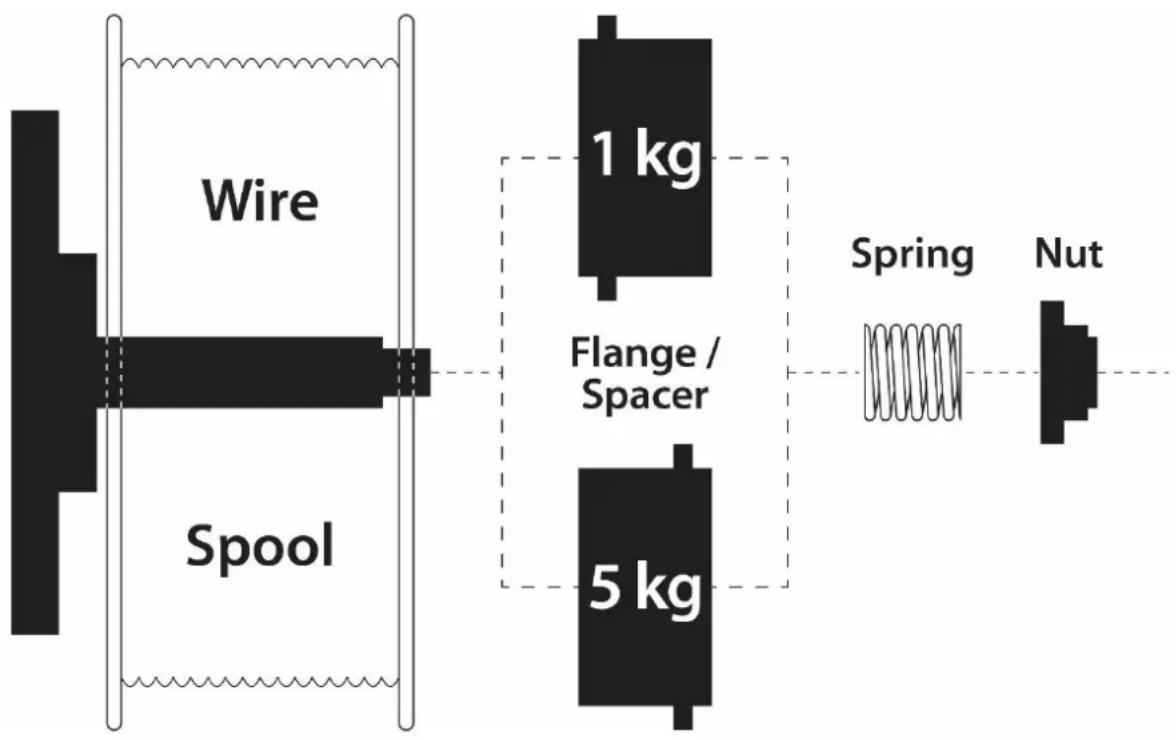
7.1.1 Fitting Wire Spool
- Open the wire feeder compartment door.
- Remove the Tension Nut & Spring
- Remove Flange/Spacer
- Fit the wire spool to the Spool Post Bolt, ensuring that the wire spool is position so that the wire will exit from bottom of spool.
-
Replace the Flange/Spacer – as per orientation shown below (orientation is different for 100mm/1kg vs 200mm/5kg spools)
-
Replace spring & Tension Nut. Note: Adjust tension so that the spool can rotate freely, but does not continue to rotate (free-wheel) once the wire feed stops.
flowchart
graph LR
    A["Wire"] --> B["Spool"]
    B --> C["1 kg"]
    B --> D["5 kg"]
    C --> E["Spring"]
    D --> F["Nut"]
Figure 7
7.1.2 Loading Wire Feeder
- Set welding process to 'MIG/MAG' (Weldforce 175MST only)
- Release the Wire Feed Tension Arm by pivoting the Tension Lever towards you from the vertical 'locked' position.
- Remove Drive Roller Retaining Cap & Drive Roller
- Check the wire Drive Roller groove matches the selected MIG wire type and size. The drive roller will have two different sized grooves; the size of the groove in use is stamped on the side of the drive roller.
Weldforce 155M: The serrated (knurled) groove side of the drive roller can be used for both Gasless MIG welding and Solid steel MIG wire in either 0.8 or 0.9mm. The smooth 'V' groove side is for 0.6mm solid steel wire.
Weldforce 175MST: For flux cored 'soft' wire, such as that used in gasless MIG welding, the drive roller groove has a serrated profile (known as knurled). For solid 'hard' MIG wire, the drive roller groove used has a 'V' shaped profile. For Aluminum MIG wire, the drive roller required has a 'U' shaped groove.
- Fit correct drive roller & replace retaining cap
- Manually feed the wire through the Wire Inlet Guide, through the Drive Roller groove and into the Wire Outlet Tube.
- Ensuring that the wire is correctly seated in the drive roller groove, replace the Wire Feed Tension Arm and lock it into place by pivoting the Wire Feed Tension Lever back to the vertical position.
- Adjusting wire feed tension by winding the Tension Lever Knob. Clockwise will increase tension, anticlockwise will decrease drive tension.
TIP! Ideal tension is as little as possible, while maintaining a consistent wire feed with no drive roller slippage.
Check all other causes of excess wire feeding friction causing slippage first, such as; incorrect contact tip size, damaged contact tip, blocked/damaged torch wire guide liner, incorrect/worn drive roller, before increasing wire feed tension.
WARNING! The use of excessive feed tension will cause rapid and premature wear of the drive roller, the support bearing and the drive motor/gearbox.
- Connect the MIG Torch to the MIG torch Euro Connector on the front of the machine (Weldforce 175MST only). Secure by firmly hand tightening the threaded collar on the MIG Torch connector.
- Check that the correct matching MIG wire, drive roller and MIG torch tip are fitted.
- Connect the machine to suitable mains power using the mains input power lead. Switch the mains power switch to 'I' (On) to power up the machine.
- You are now ready to feed the wire through the torch. With the wire feeder cover open, pull the trigger on the MIG torch to check that the wire is feeding smoothly through the feeder and into the torch.
- Remove the contact tip from the torch and lay the torch out as straight as possible.
- Pull the trigger on the torch until the wire feeds out through the end of the MIG torch.
- Replace the tip on the MIG torch and trim off any excess wire.
WARNING! DO NOT touch the wire while it is feeding as it is electrically live and you risk electrocution or injury.

Figure 8
7.1.3 Gasless Welding Setup
Weldforce 155M
-
Open the wire feeder compartment door.
-
Connect the Torch Polarity Cable (coming from bottom of machine) to the Negative Dinse Socket. Ensure the connection is tight and firm.
-
Connect the Earth Polarity Cable (coming from top of machine) to the Positive Dinse Socket. Ensure the connection is tight and firm.
-
Connect the earth clamp to the work piece. Contact with the work piece must be firm contact with clean, bare metal, with no corrosion, paint or scale at the contact point.
Note: if this connection is not made, there will be no electrical connection to the welding torch!
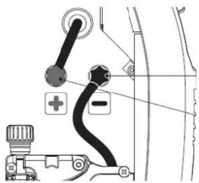
Figure 9
Weldforce 175MST
-
Connect the earth cable quick connector to the Positive Dinse Socket.
-
Connect the earth clamp to the work piece. Contact with the work piece must be firm contact with clean, bare metal, with no corrosion, paint or scale at the contact point.
-
Connect the Torch Polarity Change Tail to the Negative Dinse Socket.
Note: if this connection is not made, there will be no electrical connection to the welding torch!

natural_image
Diagram of a cable connector with wires and pliers, no text or symbols presentFigure 10
7.1.4 Gas MIG Welding Setup
NOTE: Gas MIG welding will require a gas cylinder. (Argon mix or CO2)
- Connect the gas regulator to a gas cylinder (not included with machine) and connect the gas hose from the regulator to the gas inlet connection on the rear of the machine. Ensure all hose connections are tight and clamped with the hose clamps provided.
- Open gas cylinder valve and adjust regulator. Pull the trigger on the MIG torch to initiate flow of gas through the welding torch. Flow should be between 10-25L/min depending on application.
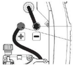
Weldforce 155M
- Open the wire feeder compartment door.
- Connect the Torch Polarity Cable (coming from bottom of machine) to the Positive Terminal. Ensure the connection is tight and firm.
- Connect the Earth Polarity Cable (coming from top of machine) to the Negative Dinse Socket. Ensure the connection is tight and firm.
- Connect the earth clamp to the work piece. Contact with the work piece must be firm contact with clean, bare metal, with no corrosion, paint or scale at the contact point.
Note: if this connection is not made, there will be no electrical connection to the welding torch!
natural_image
Diagram of a car's seatbelt mechanism showing rope, valve, and switch components (no text or labels)Figure 11
Weldforce 175MST
- Connect the earth cable quick connector to the Negative Dinse Socket.
- Connect the earth clamp to the work piece. Contact with the work piece must be firm contact with clean, bare metal, with no corrosion, paint or scale at the contact point.
- Connect the Torch Polarity Change Tail to the Positive Dinse Socket.
Note: if this connection is not made, there will be no electrical connection to the welding torch!

natural_image
Diagram of a cable being inserted into a device, showing coiled wires and a pliers (no text or symbols)Figure 12
7.1.5 Additional Setup for MIG welding with Aluminium (Weldforce 175MST only)
Welding with aluminium provides a unique challenge, due to the low column strength and surface friction of the wire. This causes the wire to deform more as it is pushed through the feed mechanism and the torch wire delivery liner, greatly increasing friction. Because good MIG welding results are dependent on a smooth wire feed, certain changes must be made to the wire feed system to minimise friction caused issues.
- A shorter MIG Torch will minimize friction and issues. If possible limit length to no longer than 3m
- Replace the liner in the MIG Torch with a special Graphite/Teflon/PVC liner (rather than the conventional steel liner). The Weldclass Universal Graphite liner kit is recommended (P3-CTUL09)
- Choose the largest diameter wire possible that can be used by your machine for your application. (Ideally 1.0mm or above)
- Ensure the wire drive system is fitted with the correct size U-groove drive roller to suit the wire being used.
- Ensure specific Aluminium contact tip to suit chosen wire (or a standard tip in one size oversize, e.g. 1.0mm aluminium wire, use standard 1.2mm contact tip).
TIP! For above reasons, it is quite common for operators to have an extra MIG torch specifically set up for aluminium use, if the machine is used for welding steel as well.
7.1.6 Settings for MIG Welding
- Follow above steps for either 'Gasless Welding Setup' or 'Gas MIG Welding Setup' (whichever is relevant)
- Set welding process selector to 'MIG' (Weldforce 175MST only)
- Rotate Output Knob to choose output power. (Refer to Charts below)
- Rotate Output Knob
- Inductance (/Arc Force) Knob to fine tune the desired setting. This can be modified to fine tune the arc characteristics to suit your exact welding application. (Refer to Charts below)
Weldforce 155M
| Settings Chart | |||||||||||
| Wire Type | Gas | Wire Size | Inductance | Material Thickness (mm) / Output Setting* | |||||||
| 0.6mm | 0.8mm | 1.0mm | 1.5mm | 2.0mm | 2.5mm | 3.0mm | 5.0mm | ||||
| Gasless / Flux-Cored Steel | - | 0.8mm | C | 1.5 | 2 | 2.5 | 3 | 3.5 | 4 | 5.5 | - |
| 0.9mm | C | 1.5 | 2 | 2.5 | 3 | 3.5 | 4 | 5 | 10 | ||
| Solid Steel | Mixed Ar+CO2 | 0.6mm | C | 2 | 2.5 | 3 | 5.5 | 7.5 | 8 | 9 | - |
| 0.8-0.9mm | B | 2 | 2.5 | 3 | 3.5 | 4.5 | 6.5 | 8 | 10 | ||
| CO2 | 0.6mm | D | 2 | 2.5 | 3 | 4 | 6.5 | 7.5 | - | - | |
| 0.8-0.9mm | D | 1.5 | 2 | 2.5 | 3 | 4 | 5 | - | - | ||
| Stainless-Steel | Ar+O2/Ar+CO2 | 0.8mm | B | 2 | 2.5 | 3.5 | 5.5 | 7.5 | 8 | 9 | - |
Table 3
*Use chart as guide only, as optimal settings will vary with weld joint type and operator technique.
Weldforce 175MST
| Settings Chart | ||||||||||||
| Wire Type | Gas | Wire Size | Inductance | Material Thickness (mm) / Output Setting* | ||||||||
| 0.6mm | 0.8mm | 1.0mm | 1.5mm | 2.0mm | 2.5mm | 3.0mm | 4.0mm | 5.0mm | ||||
| Gasless / Flux-Cored Steel | - | 0.8mm | C | 1.5 | 2 | 3 | 4 | 4.5 | 6 | 7 | 9 | - |
| 0.9mm | C | 1.5 | 2 | 2.5 | 3.5 | 4.5 | 6 | 7 | 8.5 | 9 | ||
| Solid Steel | Mixed Ar+CO2 | 0.6mm | C | 2 | 2.5 | 3 | 4.5 | 6 | 7.5 | 9 | - | - |
| 0.8-0.9mm | B | 2 | 2 | 2.5 | 3.5 | 4.5 | 5.5 | 6.5 | 8 | 10 | ||
| CO2 | 0.6mm | D | 2 | 2.5 | 3 | 4 | 5.5 | 7 | - | - | - | |
| 0.8-0.9mm | D | 1.5 | 2 | 2.5 | 3 | 3.5 | 4 | - | - | - | ||
| Stainless-Steel | Ar+O2/Ar+CO2 | 0.8mm | B | 2 | 2.5 | 3.5 | 4 | 5.5 | 7.5 | 9 | - | - |
| Aluminium | Ar | 0.9mm | A | - | 3.5 | 4.5 | 7 | 8 | 9 | - | - | - |
| 1.0mm | A | - | 3 | 3.5 | 5.5 | 7 | 9 | - | - | - | ||
| Bronze (CuSi/CuAl) | Ar | 0.8mm | A | - | 2.5 | 3.5 | 5 | 6.5 | 8.5 | - | - | - |
Table 4
*Use chart as guide only, as optimal settings will vary with weld joint type and operator technique.
7.1.1 Drive Rollers & Torch Liners for different Wires
Following are recommended drive rollers and MIG torch liners to use for various wires.
Weldforce 155M:

*Knurled groove is suitable for both Solid & Flux-cored (gasless) wires in this machine.
Weldforce 175MST:
| Wire Type | Wire Size | Drive Roller | Torch Liner | |
| Type | Part No. | |||
| Gasless/Flux-Cored Steel | 0.8mm | Knurled Groove | WC-06425 | Blue |
| 0.9mm | Red | |||
| Solid Steel | 0.6mm | V-Groove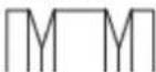 | WC-06422 | Blue |
| 0.8-0.9mm | Red | |||
| 0.6mm | Blue | |||
| 0.8-0.9mm | Red | |||
| Stainless-Steel | 0.8mm | Blue | ||
| Aluminium | 0.9mm | U-Groove | WC-06426 | Teflon / Poly |
| 1.0mm | ||||
| Bronze (CuSi/CuAl) | 0.8mm | U or V-Groove | WC-06422 | |
Table 5
7.2 Stick (MMA) Welding Operation (Weldforce 175MST only)
- Connect the earth cable quick connector to the Negative Dinse Socket
- Connect the earth clamp to the work piece. Contact with the work piece must be firm contact with clean, bare metal, with no corrosion, paint or scale at the contact point.
- Insert an electrode into the electrode holder and connect the electrode holder and work lead to the Positive Dinse Socket.
NOTE: This polarity connection configuration is valid for most GP (General Purpose) MMA electrodes. There are variances to this. If in doubt, check the electrode specifications or consult the electrode manufacturer.
- Connect the machine to suitable power. Switch the Mains Power Switch to 'on' to power up the machine.
- Set welding process selector knob to 'MMA'
- Select the required output current using the Output Knob.
- Adjust Arc Force as required using the Output Knob
- Inductance (/Arc Force) Knob.
- You are now ready to weld!

Figure 13
7.3 Lift TIG Operation (Weldforce 175MST only)
NOTE: Lift TIG operation requires an optional valved TIG torch & argon gas cylinder.
NOTE: The Weldforce 175MST is a DC (Direct Current) output welder only, this means that it is unable to TIG weld reactive metals such as Aluminium alloys and Brass (which require AC output). DC TIG output is suitable for steel, stainless steel and copper.
- Connect the earth cable to the Positive Dinse Socket
- Connect the earth clamp to the work piece. Contact with the work piece must be firm contact with clean, bare metal, with no corrosion, paint or scale at the contact point.
- Insert TIG torch power connection into the Negative Dinse Socket
- Connect TIG torch gas line to the Gas regulator and ensure gas regulator is connected to Argon gas cylinder. Ensure all connections are tight.
- Open gas cylinder valve and adjust regulator. Open gas valve on the TIG torch to test flow of gas through the TIG torch. Flow should be between 5-10 l/min depending on application.
- Connect the machine to suitable power. Switch the Mains Power Switch to 'I' to power up the machine.
- Set Process Selector Knob to 'TIG'
- Select the required output current using the Output Knob.
- You are now ready to weld!
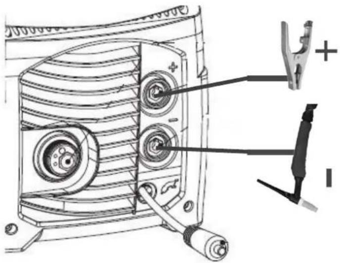
Figure 14
8 ACCESSORIES, SPARE PARTS & CIRCUIT DIAGRAMS
8.1 MIG Torch and Spares for Weldforce 155M:
The MIG Torch supplied with the Weldforce 155M is a BZL 15 (Binzel 15 style) model. To view parts for this torch, see below table or go to: http://www.weldclass.com.au/BZL15

natural_image
Exterior view of a black welding torch with attached cable (no text or symbols visible)BZL 15 Torch Parts
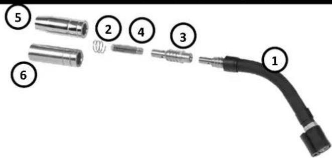
| Ref. | Part No. | Description |
| 1 | P3-B15SN | Neck |
| 2 | P3-B15NS | Nozzle Spring Pk2 |
| 3 | P3-B15TH | Tip Holder Pk2 |
| 4 | P3-BT6066 | Tip 0.6mm Pk5 |
| 4 | P3-BT6086 | Tip 0.8mm Pk5 |
| 4 | P3-BT609 | Tip 0.9mm Pk5 |
| 4 | P3-BT610 | Tip 1.0mm Pk5 |
| 4 | P3-BTA610 | Tip 1.0mm Alu Pk5 |
| 4 | P3-BTA612 | Tip 1.2mm Alu/Flux Core Pk5 |
| 5 | P3-B15N | Nozzle – Conical Pk2 |
| 6 | P3-B15NC | Nozzle – Cylindrical Pk2 |
Table 6
*For 175MST model only
8.2 MIG Torch and Spares for Weldforce 175M:
The MIG Torch supplied with the Weldforce 175M is a BZL 25 (Binzel 25 style) model. To view parts for this torch, see below table or go to: http://www.weldclass.com.au/BZL25

natural_image
Exterior view of a black welding torch with attached metal clip (no text or symbols visible)BZL 25 Torch Parts

| Ref. | Part No. | Description |
| WC-03614 | Complete Torch – 3m Euro Connection* | |
| WC-03615 | Complete Torch – 4m Euro Connection* | |
| 1 | P3-B25SN | Neck |
| 2 | P3-B25NS | Nozzle Spring Pk2 |
| 3 | P3-B25TH | Tip Holder Pk2 |
| 4 | P3-BT6066 | Tip 0.6mm Pk5 |
| 4 | P3-BT6086 | Tip 0.8mm Pk5 |
| 5 | P3-BT609 | Tip 0.9mm Pk5 |
| 5 | P3-BT610 | Tip 1.0mm Pk5 |
| 5 | P3-BTA610 | Tip 1.0mm Alu Pk5 |
| 5 | P3-BTA612 | Tip 1.2mm Alu/Flux Core Pk5 |
| 6 | P3-B25N | Nozzle – Conical Pk2 |
| P3-BBSL4 | Liner – Steel wires 0.6-0.8mm | |
| P3-BRSL4 | Liner – Steel wires 0.9-1.2mm | |
| P3-CTUL09 | Liner – Aluminium wire 0.9-1.2mm |
Table 7
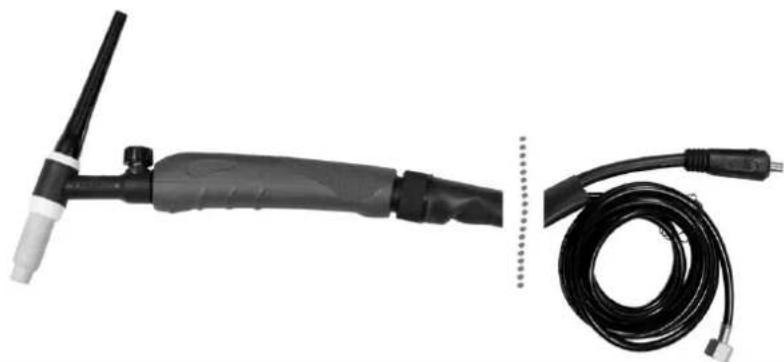
8.3 TIG Torch and Spares (Optional Extra for Weldforce 175MST only):
The compatible TIG torch for this machine is the Weldclass 3-TTU2917V/4 torch.
To view this torch and parts, go to: www.weldclass.com.au
natural_image
Exterior view of a welding torch and its black cable (no text or symbols visible)| Part No. | Description |
| 3-TTU2917V/4 | Complete TIG Torch – Valved 150A 4m |
| P3-TB17FV | Torch Body - 17F Flexible (With Valve) |
| WC-57Y02P | Back cap – Long Pk2 |
| WC-57Y05P | Back cap – Medium Pk2 |
| WC-57Y04P | Back cap – Short Pk2 |
| P3-10N23 | Collet – 1.6mm |
| P3-10N24 | Collet – 2.4mm |
| P3-10N25 | Collet – 3.2mm |
| P3-10N31 | Collect Body – 1.6mm Pk2 |
| P3-10N32 | Collect Body – 2.4mm Pk2 |
| P3-10N28 | Collect Body – 3.2mm Pk2 |
| P3-10N49 | TIG Ceramic Cup - #5 7.9mm Pk2 |
| P3-10N48 | TIG Ceramic Cup - #6 9.5mm Pk2 |
| P3-10N47 | TIG Ceramic Cup - #7 11.1mm Pk2 |
| P3-10N46 | TIG Ceramic Cup - #8 12.7mm Pk2 |
| P3-10N45 | TIG Ceramic Cup - #10 15.8mm Pk2 |
| WC-05192 | TIG Tungsten RE4 – 1.6mm Pk10 |
| WC-05193 | TIG Tungsten RE4 – 2.4mm Pk10 |
| WC-05194 | TIG Tungsten RE4 – 3.2mm Pk10 |
Table 8

Figure 15
8.4 Optional Accessories
| Optional Accessories | |
| Part No. | Drive Roller |
| 3-TTU2917V/4 | TIG Torch – Valved 150A 4m |
| WC-06235 | Welding Trolley |
| WC-01775 | Welding Gloves |
| P6-MPLY | MIG Pliers |
Table 9
8.5 Drive Rollers
| Drive Rollers | |
| Part No. | Drive Roller |
| WC-06422 | 0.6/0.8/0.9mm V-Groove (Steel) |
| WC-06425 | 0.8/0.9/1.2mm Knurled (Flux Cored) |
| WC-06426 | 0.9/1.0mm U-Groove (Aluminium) + 1.0mm V-Groove (Steel) |
Table 10
8.6 Machine Spare Parts:
For machine parts, go to www.weldclass.com.au/machines or contact your Weldclass distributor.
| Weldforce 155M | |
| Ref. | Description |
| 2 | Earth Lead Cable |
| 3 | Adjustment Knob |
| 4 | Main Power On/Off Switch |
| 5 | Input Power Lead |
| 7 | Front Panel |
| 8 | Back Panel |
| 9 | Handle |
| 21 | Work Clamp |
| 22 | MIG Torch |
| 24 | Red Terminal Clamp Kit |
| 25 | Black Terminal Clamp Kit |
| 34 | Switch Cover |
| 36 | Guide Tube |
| 37 | Spool Post |
| 38 | Wire Drive Roller |
Table 11
| Weldforce 175MST | |
| Ref. | Description |
| 1 | Potentiometer |
| 2 | Earth Lead |
| 3 | Process Selection Knob |
| 4 | Thermostat |
| 5 | Adjustment Knob |
| 6 | Solenoid Valve |
| 7 | Main Power On/Off Switch |
| 8 | Input Power Lead |
| 9 | Fan |
| 10 | Back Panel |
| 11 | Handle |
| 12 | Front Panel |
| 13 | Power Cable Gland |
| 16 | Wire Compartment Door Handle |
| 17 | Guide |
| 19 | Wire Compartment Door |
| 20 | Back Panel |
| 21 | Front Panel |
| 22 | Diaphram |
| 23 | Earth Clamp |
| 24 | Dinse Socket |
| 25 | Polarity Change Lead Dinse Plug |
| 26 | Wire Drive Roller |
| 27 | Euro Torch Socket |
| 28 | MIG Torch |
| 29 | Mosfet Flyback Kit |
| 30 | Diode Kit |
| 31 | Single Phase Bridge Kit |
| 32 | IGBT & Diode Kit |
| 33 | Capacitor Kit Snap-in |
| 34 | Bottom Kit |
| 35 | Drive System Kit |
| 36 | Front Control Panel Kit |
| 37 | Complete Main PCB Kit |
| 38 | Cover Kit (Metal Panels) |
| 39 | Guide Tube |
| 40 | Spool Post |
| 41 | Process Selection Switch |
| 42 | Main Power Switch Cover |
Weldforce 155M

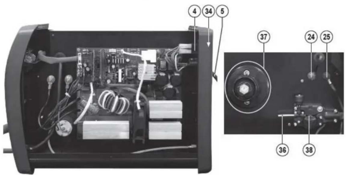
Figure 16
Weldforce 175MST

Figure 17
8.7 Primary Schematic Circuit Diagram

Figure 18
9.1 Keep your Welding Machine in Top Condition
These machines not require any special maintenance, however the user should take care of the machine as follows:
- Regularly clean the ventilation slots
- Keep the casing clean
- Check all cables before use
- Check electrode holders, work lead/clamps and welding torches before use
- Replace worn electrode holders and earth clamps, which do not provide a good connection
- Replace worn torch consumable parts in a timely manner
- Replace worn wire drive components in a timely manner
- Use a soft cloth or brush to clean electrical components. Do not use liquid cleaning products, water or especially solvents
- Do not use compressed air to clean electrical components as this can force dirt and dust further into components, causing electrical short circuits
- Check for damaged parts
WARNING! Before performing cleaning/maintenance, replacing cables/connections, make sure the welding machine is switched off and disconnected from the power supply.
If damaged, before further use, the welder must be carefully checked by a qualified person to determine that it will operate properly. Check for breakage of parts, mountings and other conditions that may affect its operation.
Have your welder repaired by an expert. An authorised service centre should properly repair a damaged part.
This appliance is manufactured in accordance with relevant safety standards. Only experts must carry out repairing of electrical appliances, otherwise considerable danger for the user may result.
Use only genuine replacement parts. Do not use modified or non-genuine parts.
9.2 Storing the Welder
When not in use the welder should be stored in the dry, dust-free and frost-free environment.
10 GENERAL GUIDE TO WELDING
10.1 Duty Cycle Rating
Weldforce welding machines are fitted with thermal overload protection which means the machine will cut out when it reaches a certain temperature, to prevent damage to components. The machine will then re-start when it returns to a safe temperature.
Duty cycle is a measure of the percentage of time a machine will operate within a certain time period at a given amperage. For example a duty cycle of 160A @ 25% means that a machine will operate at 160A for 2½ minutes in a 10 minute time period. The machine will have to rest for the remaining 7½ minutes to enable it to cool down.
The international standard for duty cycle rating is based on an ambient air temperature of 40^ C with 50% humidity, over a 10 minute period. In an environment with temperatures exceeding 40^ C, the duty cycle will be less than stated. In ambient temperature less than 40^ C, duty cycle performance will be higher. There are numerous other factors that can influence actual duty cycle performance.
10.2 Choosing a Welding Process – MIG, Stick or TIG?
10.2.1 The Stick (MMA) Process
10.2.1.1 Description
The acronym MMA (or MMAW) stands for Manual Metal Arc Welding. 'Manual' refers to the fact that the MMA process requires the operator to apply filler metal (in contrast to MIG 'semi-automatic' welding where the machine feeds the filler metal into the weld). 'Metal' refers to the fact that the filler metal itself (the stick electrode) is used to conduct the welding current to the job. MMA welding is commonly known as 'stick-electrode' or 'arc' welding.
10.2.1.2 Process
The MMA process involves the electrode being touched on the job to ignite the arc. The electrode is held in the electrode holder and must be continually replaced as it is consumed. The electrode consists of a metal core, which is the filler metal, covered by a flux coating which shields the weld and prevents it from oxidising. During welding the flux forms into a slag covering the weld which is chipped off after the weld has formed.
10.2.1.3 Advantages
MMA welding offers several advantages over alternative welding processes. Primarily it has a greater capacity than MIG welding, or in other words it can weld heavier materials with the same amperage output. For this reason small, portable inverter welders like the Weldforce machines, have the capacity to weld with up to 3.2mm or 4mm electrodes making it suitable for a vast range of applications without the complication of shielding gas or wire feeding. Moreover, MMA welding is typically more 'forgiving' than MIG or TIG when welding rusty or dirty materials (which makes it ideal for maintenance applications).
10.2.1.4 Limitations
Traditionally, welding thin materials whilst avoiding “blow-through” can be tricky with the MMA process. This being said, however, welding thin materials with a Weldforce machine will be noticeably easier because the arc is so stable and the output can be very finely adjusted down to very low amps.
10.2.1.5 Materials
MMA welding can be used with a wide variety of electrodes including general purpose, low hydrogen, stainless steel, iron powder, hard facing & cast iron just to name a few.
10.2.2 The TIG Process
10.2.2.1 Description
The acronym TIG stands for Tungsten Inert Gas. Tungsten refers to the type of conductor (a tungsten electrode) that is used to transfer the welding current to the job and create the arc. Inert Gas refers to the fact that the process relies on an inert gas to prevent weld oxidisation.
Also referred to as Gas Tungsten Arc Welding (GTAW).
10.2.2.2 Process
In simple terms, TIG welding is probably most similar to oxy flame welding. However, instead of a flame it uses an electrical arc to melt the job and filler metal, and instead of a preheat flame it uses inert gas to prevent weld oxidisation. Like oxy flame welding, the filler metal is fed into the weld by hand as required. Due to the fact that the current is not conducted to the job via the filler metal, (as it is in MIG and MMA welding), the arc is much more controllable.
10.2.2.3 Advantages
Very low amperages can be achieved making this process ideal for welding thin materials. Also, due to the independence of the arc and the filler metal application, TIG welding is very controllable and can therefore achieve very high quality welds with excellent appearance. Unlike MIG and MMA welding, TIG welding does not produce spatter so clean up is very minimal. It is typically used where weld appearance is critical (e.g. handrails) or where weld quality is vital (e.g. pressure vessels or pipes).
10.2.2.4 Limitations
Whilst TIG welding is very controllable, it can also be slower and more tedious than MIG or MMA welding and it will generally not operate well on dirty or rusty materials meaning that additional weld preparation is sometimes necessary. It also requires a higher level of skill and experience to achieve a quality result.
10.2.2.5 Materials
This machine incorporates DC TIG function which can be used to weld a variety of materials including mild steels, stainless steels, copper and chrome moly.
Note: TIG welding is often associated with welding of aluminium, however, aluminium TIG welding is only possible with AC/DC TIG welding machines. This machine is DC only and is not designed for TIG welding of aluminium.
10.2.3 The MIG Process
10.2.3.1 Description
The acronym MIG stands for Metal Inert Gas. Metal' refers to the fact that the filler metal itself (the MIG wire) is used to conduct the welding current to the job and create the arc. Inert Gas refers to the fact that the process relies on an inert gas to prevent weld oxidisation. The acronym MAG is also often used which stands for Metal Active Gas. MAG is fundamentally the same as MIG except that MAG technically refers to when Carbon Dioxide (CO2) is used as a shielding gas (instead of an inert gas of argon, helium or a mixed gas with these as a base).
The process is also referred to as Gas Metal Arc Welding (GMAW) when gas is used or Flux-Cored Arc Welding (FCAW) when flux-cored or gasless/self-shielded wire is used.
10.2.3.2 Process
The MIG welding process involves the filler wire being fed through a torch/gun to the job. The filler wire carries the welding current to the job. The weld pool is generally covered by an inert gas supplied from the torch which shields the weld and prevents it from oxidising. However, gasless welding wire can be used without any shielding gas. This gasless wire has a hollow core filled with flux which shields the weld and prevents it from oxidising. During welding this flux forms into a slag covering the weld which is chipped off after the weld has formed.
10.2.3.3 Advantages
MIG welding is both easy and fast. Once weld settings are adjusted, the filler wire is fed automatically into the weld at the correct rate. It does not rely on the operator to feed in filler wire like TIG welding.
Also because the filler wire is on a roll it lasts significantly longer than a Stick welding electrode so
there is much less downtime in replacing filler wire. MIG can also weld with thin wires at low amperages achieving great results on thin materials. At the same time, bigger diameter wires and higher amperages can be used to weld thicker materials with good penetration. When a shielding gas is used there is no flux formed on the weld so clean up is minimal.
10.2.3.4 Limitations
MIG welding with shielding gas cannot be done in windy environments. However, in many applications gasless/self-shielding wires are available that don't require gas. MIG traditionally requires a higher level of skill and experience to be able to balance voltage and wire speed settings well to achieve a quality result. However, the Synergic programs on this machine make this very easy and much more foolproof.
10.2.3.5 Materials
MIG welding can be used with a wide variety of wires including steel, stainless steel, gasless wires, aluminium, silicone bronze & hard facing just to name a few.
10.3 Joint Preparations
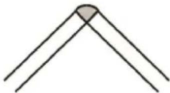
In many cases, it will be possible to weld steel sections without any special preparation. For heavier sections and for repair work on castings, etc., it will be necessary to cut or grind an angle between the pieces being joined to ensure proper penetration of the weld metal and to produce sound joints. In general, surfaces being welded should be clean and free of rust, scale, dirt, grease, etc. Slag should be removed from oxy-cut surfaces. Typical joint designs are shown in the following figures.
Open Square Butt Joint
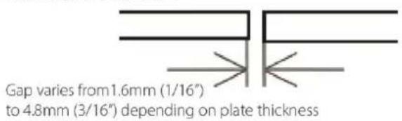
Figure 19
Double Vee Butt Joint
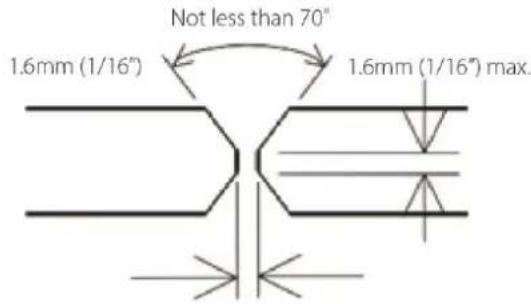
Figure 22
Single Vee Butt Joint
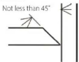
Figure 20
Lap Joint

Figure 23
Single Vee Butt Joint
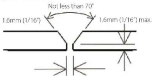
Figure 21
Fillet Joint
Figure 24

Tee Joints

natural_image
Simple diagram showing two vertical lines above a horizontal line, with two shaded semicircular regions below (no text or symbols)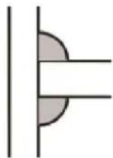
natural_image
Pure diagram of a pipe fitting with no text or symbolsFigure 26
Corner Weld
natural_image
Simple geometric diagram of two intersecting lines forming an angle (no text or symbols)Figure 27
Plug Welds

natural_image
3D rendering of a metallic L-shaped bracket with two circular holes on top (no text or symbols)
natural_image
3D rendered mechanical part with a circular feature on top, showing layered structure (no text or symbols)Figure 28
11 MIG BASIC WELDING GUIDE
11.1 MIG Basic Welding Techniques
Two different welding processes are covered in this section (GMAW and FCAW), with the intention of providing the very basic concepts in MIG welding, where a welding torch is hand held, and the electrode (welding wire) is fed into a weld pool, and the arc is shielded by a gas (GMAW) or flux cored wire (FCAW).
11.2 Gas Metal Arc Welding (GMAW)
This process, also known as MIG welding, CO2 welding, Micro Wire Welding, short arc welding, dip transfer welding, wire welding etc. It is an electric arc welding process which fuses together the parts to be welded by heating them with an arc between a solid continuous, consumable electrode and the work. Shielding is obtained from an externally supplied welding grade shielding gas. The process is normally applied semi automatically; however the process may be operated automatically and can be machine operated. The process can be used to weld thin and fairly thick steels and some nonferrous metals in all positions.
GMAW Process

Figure 29
11.3 Flux Cored Arc Welding (FCAW)
This is an electric arc welding process which fuses together the parts to be welded by heating them with an arc between a continuous flux-filled welding wire and the work. Shielding is obtained through decomposition of the flux within the tubular wire. Additional shielding may or may not be obtained from an externally supplied gas or gas mixture. The process is normally applied semi automatically; however the process may be applied automatically or by machine. It is commonly used to weld large diameter wires in the flat and horizontal position and small wire diameters in all positions. The process is used to a lesser degree for welding stainless steel and for overlay work.
FCAW Process

Figure 30
11.4 Position of MIG Torch
The angle of MIG torch to the weld has an effect on the width of the weld. The welding torch should be held at an angle to the weld joint. (See Secondary Adjustable Variables below). Hold the torch so that the welding seam is viewed at all times. Always wear the welding helmet with proper filter lenses and use the proper safety equipment.
CAUTION! Do not pull the welding torch back when the arc is established. This will create excessive wire extension (stick-out) and make a very poor weld.
The welding wire is not energized until the torch trigger switch is depressed. The wire may therefore be placed on the seam or joint prior to lowering the helmet.
Position of MIG Torch

Push

Vertical
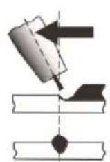
Drag Pull
Figure 31
11.5 Distance from the MIG Torch Nozzle to the Work Piece
The welding wire stick out from the MIG Torch nozzle should be between 10mm to 20mm. This distance may vary depending on the type of joint and type of wire that is being welded. Generally solid wire is about 10mm and flux-cored/gasless wire about 15-20mm.
11.6 Travel Speed
The speed at which the molten pool travels influences the width of the weld and penetration of the welding run.
11.7 MIG Welding (GMAW) Variables
Most of the welding done by all processes is on carbon steel. The items below describe the welding variables in short-arc welding of 0.6mm to 6mm mild sheet or plate. The applied techniques and end results in the MIG process are controlled by these variables.
11.7.1 Preselected Variables
Preselected variables depend upon the type of material being welded, the thickness of the material, the welding position, the deposition rate and the mechanical properties.
These variables are:
- Type of welding wire
- Size of welding wire
- Type of shielding gas
- Gas flow rate
11.7.2 Primary Adjustable Variables
These control the process after preselected variables have been found. They control the penetration, bead width, bead height, arc stability, deposition rate and weld soundness.
These variables are:
- Arc Voltage & Wire feed speed (adjusted simultaneously on Synergic machines)
- Inductance
- Travel speed
11.7.3 Secondary Adjustable Variables
These variables cause changes in primary adjustable variables which in turn cause the desired change in the bead formation. They are:
- Stick-Out: This is the distance between the end of the contact tube (tip) and the end of the welding wire). Maintain at about 10mm stick-out for solid wire and 15-20mm for gasless wire.

Figure 32
- Nozzle Angle: This refers to the position of the welding torch in relation to the joint. The transverse angle is usually one half the included angle between plates forming the joint. The longitudinal angle is the angle between the centre line of the welding torch and a line perpendicular to the axis of the weld. The longitudinal angle is generally called the Nozzle Angle and can be either trailing (pulling) or leading (pushing).
Whether the operator is left handed or right handed has to be considered to realize the effects of each angle in relation to the direction of travel.
Transverse & Longitudinal Nozzle Axes

Figure 33
Nozzle Angle, Right Handed Operator

Figure 34
Horizontal Butt Weld

Figure 35
Vertical Fillet Welds

Figure 37
Horizontal Fillet Weld

Figure 36
Overhead Fillet Weld
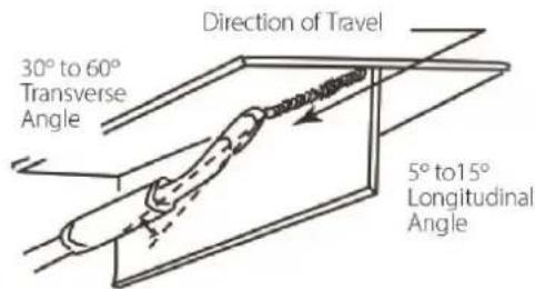
Figure 38
11.8 Establishing the Arc and Making Weld Beads
Before attempting to weld on a finished piece of work, it is recommended that practice welds be made on a sample metal of the same material as that of the finished piece. The easiest welding procedure for the beginner to experiment with MIG welding is the flat position. The equipment is capable of flat, vertical and overhead positions. For practicing MIG welding, secure some pieces of 1.6mm or 2.0mm mild steel plate (150 x 155Mm). Use 0.9mm flux cored gasless wire or a solid wire with shielding gas.
11.9 MIG Output Settings
Manual MIG welding setting requires some practice by the operator, as the machine has two control settings that have to balance. These are the Wire Speed control and the welding Voltage control.
Voltage is essentially the power in the welding arc that sets the heat. The wire speed feed simply controls the rate at which the welding wire is fed into the weld pool. For any voltage position setting, there will be a specific corresponding 'sweet spot' in the wire feeding speed that will give the smoothest and most stable welding arc. The correct wire feeding speed for a given voltage setting is affected by welding wire type and size, shielding gas, welding material and joint type.
Synergic function makes the setup of MIG welding much simpler as follows:
- Select output setting (the machine calculates the optimal voltage and wire speed ratio)
- Adjust inductance setting to refine arc characteristics
- Obviously other variables such as welding joint type, position and thickness, air temperature can affect the optimal voltage and wire feed setting, so voltage can be adjusted to fine-tune for optimal performance.
11.9.1 Changing to a different welding wire
When changing to a different welding wire diameter, different control settings are required. A thinner welding wire needs more Current (Wire Speed) to achieve the same current level. A satisfactory weld cannot be obtained if the Current (Wire Speed) and Voltage settings are not adjusted to suit the welding wire diameter and the dimensions of the work piece.
11.10 Welding wire Size Selection
The choice of Welding wire size and shielding gas used depends on the following:
- Thickness of the metal to be welded
- Type of joint
- Capacity of the wire feed unit and power source
- The amount of penetration required
- The deposition rate required
- The bead profile desired
- The position of welding
- Cost of the wire
- Environment (can shielding gas be used or not?)
11.11 MIG Welding Troubleshooting
The general approach to fix MIG welding problems is to start at the wire spool then work through to the MIG torch. There are two main areas where problems occur with MIG: Porosity and Inconsistent wire feed.
11.11.1 Porosity Problems
When there is a gas problem the result is usually porosity within the weld metal. Porosity always porosity within the weld metal. Porosity always stems from some contaminant within the molten weld pool which is in the process of escaping during solidification of the molten metal.
Figure 39
Contaminants range from no gas around the welding arc to dirt on the workpiece surface. Porosity can be reduced by checking the following points.
Fault
Shielding gas cylinder contents and gas regulator Gas leaks
Internal gas hose in the Power Source
Welding in a windy environment
Welding dirty, oily, painted, oxidized or greasy plate Distance between the MIG torch nozzle and the work piece Maintain the MIG torch in good working order.
Cause
Ensure that the shielding gas cylinder is not empty and the gas regulator is correctly adjusted to at least 15 litres per minute. Check for gas leaks between the regulator/cylinder connection and in the gas hose to the Power Source.
Ensure the hose from the solenoid valve to the torch adaptor has not fractured and that it is connected to the torch adaptor. This should only be done by qualified technician.
Shield the weld area from the wind or increase the gas flow or use gasless welding wire
Clean contaminates off the work piece.
Keep the distance between the MIG torch nozzle and the work piece to a minimum.
Ensure that the gas holes are not blocked in the tip holder and gas is exiting out of the torch nozzle.
Do not restrict gas flow by allowing spatter to build up inside the torch nozzle.
Check that the MIG torch O-rings are not damaged on the Euro connector.
Table 12
WARNING! Disengage the feed roll when testing for gas flow by ear
11.11.2 Wire Feed Problems
TOP TIPS - Wire Jam Troubleshooting
- If wire jam occurs when the torch becomes hot, this is often because the heat causes the wire and the top to expand (which shrinks the hole in the tip). Using a slightly oversize tip can prevent this – e.g.: for 0.9mm wire, use a 1.0mm tip.
- Do NOT over-tighten the drive roll tension – this will accelerate wear if the drive system, distort the wire & will cause further wire feed problems.
Table 13
Wire feeding problems can be reduced by checking the following points.
The most common faults are marked with * :
| Troubleshooting – Wire Feed | |
| Fault | Cause |
| Feed roller driven by motor in the cabinet slipping | Wire spool brake is too tight. |
| Wire spool unwound and tangled. | Wire spool brake is too loose. |
| Worn or incorrect feed roller size | Use a feed roller matched to the size you are welding. |
| Replace feed roller if worn. | |
| Wire rubbed against the misaligned guides affecting the wire feed. | Misalignment of inlet/outlet guides. |
| * Liner blocked with swarf (Replace liner) | Increased amounts of swarf are produced by the wire passing through the feed roller when excessive pressure is applied to the pressure roller adjuster. |
| Swarf can also be produced by the wire passing through an incorrect feed roller groove shape or size. | |
| Swarf is fed into the conduit liner where it accumulates thus reducing wire feed. | |
| * Incorrect or worn contact tip | The contact tip transfers the weld current to the electrode wire. If the hole in the contact tip is too large then arcing may occur inside the contact tip resulting in the wire jamming in the contact tip. |
| When using soft wire such as aluminum it may become jammed in the contact tip due to expansion of the wire when heated. A contact tip designed for soft wires should be used. | |
| Poor work lead contact to work piece. | If the work lead has a poor electrical contact to the work piece then the connection point will heat up and results in reduction of power at the arc. |
| Bent liner (Replace liner) | This will cause friction between the wire and the liner this reducing wire feed. |
Table 14
11.11.3 Weld Quality Problems
Other weld problems can be reduced by checking the following points.
| Troubleshooting - MIG Weld Quality | ||
| Fault | Cause | Remedy |
Undercut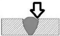 Figure 40 Figure 40 | Welding arc voltage too high | Decrease voltage or increase the wire feed speed. |
| Incorrect torch angle | Adjust angle. | |
| Excessive heat input | Increase the torch travel speed and/or decrease welding current by decreasing the voltage or decreasing the wire feed speed. | |
Lack of penetration Figure 41 Figure 41 | Welding current too low. | Increase welding current by increasing wire feed speed and increasing voltage. |
| Joint preparation too narrow or gap too tight. | Increase joint angle or gap. | |
| Shielding gas incorrect. | Change to a gas which gives higher penetration. | |
Lack of fusion Figure 42 Figure 42 | Voltage too low | Increase voltage |
Excessive spatter Figure 43 Figure 43 | Voltage too high | Decrease voltage or increase the Current (Wire Speed) control/ |
| Voltage too low. | Increase the voltage or decrease Current (Wire Speed) | |
| Irregular weld shape | Incorrect voltage and current settings.Convex, voltage too low.Concave, voltage too high. | Adjust voltage and current by adjusting the voltage control and the Current (Wire Speed) control |
| Wire is wandering. | Replace contact tip. | |
| Incorrect shielding gas. | Check shielding gas. | |
| Insufficient or excessive heat input. | Adjust the Current (Wire Speed) control or the voltage control. | |
Weld cracking Figure 44 Figure 44 | Weld bead is too small. | Decrease travel speed. |
| Weld penetration narrow and deep. | Reduce current and voltage and increase MIG torch travel speed or select a lower penetration shielding gas. | |
| Excessive weld stresses. | Increase weld metal strength or revise design. | |
| Excessive voltage. | Decrease voltage. | |
| Cooling rate too fast. | Slow the cooling rate by preheating part to be welded or cool slowly. | |
| Troubleshooting – MIG Weld Quality | ||
| Fault | Cause | Remedy |
| Cold weld puddle | Loose welding cable connection. | Check all welding cable connections |
| Low power supply voltage. | Contact supply authority | |
| Arc does not have a crisp sound that short arc exhibits when the wire feed speed and voltage are adjusted correctly | The MIG torch has been connected to the wrong voltage polarity on the front panel. | Connect the MIG torch to the positive (+) welding terminal for solid wires and negative (-) welding terminal for gasless wires.Refer to the wire manufacturer for the correct polarity. |
Table 15
12 STICK (MMA) BASIC WELDING GUIDE
12.1 Size of Electrodes
The electrode size is determined by the thickness of metals being joined and can also be governed by the type of welding machine available. Small welding machines will only provide current (amperage) to run smaller sized electrodes. For thin sections, it is necessary to use smaller electrodes otherwise the arc may burn holes through the job. A little practice will soon establish the most suitable electrode for a given application.
12.2 Storage of Electrodes
Always store electrodes in a dry place and in their original containers. If electrodes have been exposed to moisture or moist air then they will need to be dried out using an electrode drying oven.
12.3 Electrode Polarity
Electrodes are generally connected to the electrode holder with the electrode holder connected positive polarity.
The work lead is connected to the negative polarity and is connected to the work piece. If in doubt consult the electrode data sheet.
12.4 Effects of Stick (MMA) Welding on Various Materials
12.4.1 High Tensile and Alloy Steels
The two most prominent effects of welding these steels are the formation of a hardened zone in the weld area, and, if suitable precautions are not taken, the occurrence in this zone of under-bead cracks. Hardened zone and under-bead cracks in the weld area may be reduced by using the correct electrodes, preheating, using higher current settings, using larger electrodes sizes, short runs for larger electrode deposits or tempering in a furnace.
12.4.2 Manganese Steels
The effect on manganese steel of slow cooling from high temperatures causes embrittlement. For this reason it is absolutely essential to keep manganese steel cool during welding by quenching after each weld or skip welding to distribute the heat.
12.4.3 Cast Iron
Most types of cast iron, except white iron, are weldable. White iron, because of its extreme brittleness, generally cracks when attempts are made to weld it. Trouble may also be experienced when welding white-heart malleable, due to the porosity caused by gas held in this type of iron.
12.5 Types of Electrodes
Arc Welding electrodes are classified into a number of groups depending on their applications. There are a great number of electrodes used for specialised industrial purposes which are not of particular interest for everyday general work. These include some low hydrogen types for high tensile steel, cellulose types for welding large diameter pipes, etc. The range of electrodes dealt with in this publication will cover the vast majority of applications likely to be encountered; are all easy to use.
12.5.1 MILD STEEL:
- General Purpose "GP" E6013 (Weldclass 12V): This all-position electrode is used for maintenance and fabrication. Works well on mild steel, galvanized steel, sheet metal, steel tube and RHS. Its soft arc has minimal spatter, moderate penetration and an easy-to-clean slag. Tolerant to dirty / rusty steel & poor fit up. This is the most common type of electrode used for Stick welding.
- Hydrogen Controlled E7016 (Weldclass 16XT): A "low-hydrogen" electrode commonly used for mild or high strength steel, where the joint requires higher strength than regular "GP" electrodes, such as highly restrained joints or components subject to higher load stress. Also used as a buffer layer prior to hard facing. All-Positional (except for vertical down), easy striking & smooth running, with low spatter & easy slag removal..
12.5.2 CAST IRON:
- Cast Iron Ni-Cl (NCI): Suitable for joining all cast irons (Suitable for mehanite, alloy and malleable cast iron) except white cast iron. Weld positions: flat, horizontal.
12.5.3 STAINLESS STEEL:
- Stainless Steel 316L: Used for welding common 300 series stainless steels such as 301, 302, 304, 304L and 316L. All welding positions, excluding vertical down. Very Smooth Running and Easy to use.
- Universal 312: Weld-all style electrodes for welding almost any steel or stainless-steel, including dissimilar metals. Weld metal is very crack resistant. Commonly used for repair and maintenance welding of unknown steels. All welding positions excluding vertical down.
12.6 Suggested Settings for Typical Stick (MMA) Applications
| Material | Electrode Type | Electrode Size | Amperage Range |
| Mild Steel | General PurposeWeldclass E12V (E6013) | 2.6mm | 60 – 100 |
| 3.2mm | 100 – 140 | ||
| 4.0mm | 140 – 190 | ||
| Mild Steel | Hydrogen Controlled (High Strength)Weldclass 16XT (E7016) | 2.5mm | 60 – 110 |
| 3.2mm | 90 – 140 | ||
| 4.0mm | 130 – 190 | ||
| Stainless Steel | Stainless Steel316L | 2.6mm | 40 – 70 |
| 3.2mm | 100 – 150 | ||
| 4.0mm | 135 – 180 |
Table 16
These settings are a guide only. Actual settings required will depend on plate thickness, operator technique, environment, etc.
12.7 MMA Welding Techniques
12.7.1 A Word for Beginners
For those who have not yet done any welding, the simplest way to commence is to run beads on a piece of scrap plate. Use mild steel plate about 6.0mm thick and a 3.2mm electrode.
Clean any paint, loose scale or grease off the plate and set it firmly on the work bench so that welding can be carried out in the down hand position. Make sure that the Work Lead/Clamp is making good electrical contact with the work, either directly or through the work table. For light gauge material, always clamp the work lead directly to the job, otherwise a poor circuit will probably result.
12.7.2 The Welder
Place yourself in a comfortable position before beginning to weld. Get a seat of suitable height and do as much work as possible sitting down. Don't hold your body tense. A taut attitude of mind and a tensed body will soon make you feel tired. Relax and you will find that the job becomes much easier. You can add much to your peace of mind by wearing a leather apron and gauntlets. You won't be worrying then about being burnt or sparks setting alight to your clothes.
Place the work so that the direction of welding is across, rather than to or from, your body. The electrode holder lead should be clear of any obstruction so that you can move your arm freely along as the electrode burns down. If the lead is slung over your shoulder, it allows greater freedom of movement and takes a lot of weight off your hand. Be sure the insulation on your cable and electrode holder is not faulty; otherwise you are risking an electric shock.
12.7.3 Striking the Arc
Practice this on a piece of scrap plate before going on to more exacting work.
You may at first experience difficulty due to the tip of the electrode “sticking” to the work piece. This is caused by making too heavy a contact with the work and failing to withdraw the electrode quickly enough. A low amperage will accentuate it. This freezing on of the tip may be overcome by scratching the electrode along the plate surface in the same way as a match is struck.
Another difficulty you may meet is the tendency, after the arc is struck, to withdraw the electrode so far that the arc is broken again. A little practice will soon remedy both of these faults.
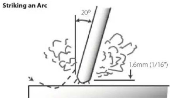
Figure 45
12.7.4 Arc Length
As soon as the arc is established, maintain a 1.6mm to 3.2mm gap between the burning electrode end and the parent metal. Draw the electrode slowly along as it melts down. The securing of an arc length necessary to produce a neat weld soon becomes almost automatic. You will find that a long arc produces more heat.
A very long arc produces a crackling or spluttering noise and the weld metal comes across in large, irregular blobs. The weld bead is flattened and spatter increases. A short arc is essential if a high quality weld is to be obtained although if it is too short there is the danger of it being blanketed by slag and the electrode tip being solidified in. If this should happen, give the electrode a quick twist back over the weld to detach it.
12.7.5 Rate of Travel
After the arc is struck, your next concern is to maintain it, and this requires moving the electrode tip towards the molten pool at the same rate as it is melting away. At the same time, the electrode has to move along the plate to form a bead.
The electrode is directed at the weld pool at about 20^ from the vertical. The rate of travel has to be adjusted so that a well-formed bead is produced.
If the travel is too fast, the bead will be narrow and strung out and may even be broken up into individual globules. If the travel is too slow, the weld metal piles up and the bead will be too large.
12.8 Making Welded Joints
Having attained some skill in the handling of an electrode, you will be ready to go on to make up welded joints.
12.8.1 Butt Welds
Set up two plates with their edges parallel, as shown in Figure 46, allowing 1.6mm to 2.4mm gap between them and tack weld at both ends. This is to prevent contraction stresses from the cooling weld metal pulling the plates out of alignment.
Plates thicker than 6.0mm should have their mating edges beveled to form a 70° to 90° included angle. This allows full penetration of the weld metal to the root. Using a 3.2mm Weldclass 12V Stick electrode at 100 amps, deposit a run of weld metal on the bottom of the joint.
Do not weave the electrode, but maintain a steady rate of travel along the joint sufficient to produce a well-formed bead. At first you may notice a tendency for undercut to form, but keeping the arc length short, the angle of the electrode at about 20^ from vertical, and the rate of travel not too fast, will help eliminate this.
The electrode needs to be moved along fast enough to prevent the slag pool from getting ahead of the arc. To complete the joint in thin plate, turn the job over, clean the slag out of the back and deposit a similar weld.
Heavy plate will require several runs to complete the joint. After completing the first run, chip the slag out and clean the weld with a wire brush. It is important to do this to prevent slag being trapped by the second run. Subsequent runs are then deposited using either a weave technique or single beads laid down in the sequence shown in Figure 47. The width of weave should not be more than three times the core wire diameter of the electrode.
When the joint is completely filled, the back is either machined, ground or gouged out to remove slag which may be trapped in the root, and to prepare a suitable joint for depositing the backing run. If a backing bar is used, it is not usually necessary to remove this, since it serves a similar purpose to the backing run in securing proper fusion at the root of the weld.

Figure 46

flowchart
graph TD
    A["1"] --> B["2"]
    B --> C["3"]
    C --> D["4"]
    D --> E["5"]
    E --> F["6"]
    F --> G["7"]
    G --> H["8"]
    H --> I["9"]
    I --> J["10"]
    J --> K["11"]
    K --> L["12"]
    L --> M["13"]
    M --> N["14"]
    N --> O["15"]
    O --> P["16"]
    P --> Q["17"]
Figure 47
12.8.2 Fillet Welds
These are welds of approximately triangular cross-section made by depositing metal in the corner of two faces meeting at right angles. Refer Figure 48 and Figure 49.
A piece of angle iron is a suitable specimen with which to begin, or two lengths of strip steel may be tacked together at right angles. Using a 3.2mm Weldclass 12V Stick electrode at 100 amps, position angle iron with one leg horizontal and the other vertical. This is known as a horizontal-vertical (HV) fillet. Strike the arc and immediately bring the electrode to a position perpendicular to the line of the fillet and about 45° from the vertical. Some electrodes require being sloped about 20° away from the perpendicular position to prevent slag from running ahead of the weld. Refer to Figure 48.
Do not attempt to build up much larger than 6.4mm width with a 3.2mm electrode, otherwise the weld metal tends to sag towards the base, and undercut forms on the vertical leg. Multi-runs can be made as shown in Figure below. Weaving in HV fillet welds is undesirable.

Figure 48
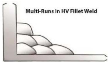
Figure 49
12.8.3 Vertical Welds
12.8.3.1 Vertical Up
Tack weld a three feet length of angle iron to your work bench in an upright position. Use a 3.2mm Weldclass 12V Stick electrode and set the current at 100 amps. Make yourself comfortable on a seat in front of the job and strike the arc in the corner of the fillet. The electrode needs to be about 10^ from the horizontal to enable a good bead to be deposited.
Refer Figure 50.
Single Run Vertical Fillet Weld

natural_image
Simple line drawing of a ruler measuring a cylindrical object inside a rectangular frame (no text or symbols)Figure 50
Use a short arc, and do not attempt to weave on the first run. When the first run has been completed deslag the weld deposit and begin the second run at the bottom. This time a slight weaving motion is necessary to cover the first run and obtain good fusion at the edges.
At the completion of each side motion, pause for a moment to allow weld metal to build up at the edges, otherwise undercut will form and too much metal will accumulate in the centre of the weld. Figure 51 illustrates multi-run technique and Figure 52 shows the effects of pausing at the edge of weave and of weaving too rapidly.

Figure 51
Examples of Vertical Fillet Welds
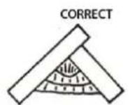
Pause at edge of weave allows weld metal to build up and eliminates undercut

Note: Weld contour when insufficient pause at edge of weave
Figure 52
12.8.3.2 Vertical Down
The Weldclass 12V Stick electrode makes welding in this position particularly easy. Use a 3.2mm electrode at 100 amps. The tip of the electrode is held in light contact with the work and the speed of downward travel is regulated so that the tip of the electrode just keeps ahead of the slag. The electrode should point upwards at an angle of about 45°.
12.8.4 Overhead Welds
Apart from the rather awkward position necessary, overhead welding is not much more difficult that down hand welding. Set up a specimen for overhead welding by first tacking a length of angle iron at right angles to another piece of waste pipe. Then tack this to the work bench or hold in a vice so that the specimen is positioned in the overhead position as shown in the sketch.
The electrode is held at 45° to the horizontal and tilted 10° in the line of travel (Figure 53). The tip of the electrode may be touched lightly on the metal, which helps to give a steady run. A weave technique is not advisable for overhead fillet welds.
Use a 3.2mm Weldclass 12V Stick electrode at 100 amps, and deposit the first run by simply drawing the electrode along at a steady rate. You will notice that the weld deposit is rather convex, due to the effect of gravity before the metal freezes.

Figure 53
12.9 MMA (Stick) Troubleshooting
| Fault | Cause | Remedy |
A gap is left by failure of the weld metal to fill the root of the weld. Figure 54 Figure 54 | Welding current too low. | Increase welding current. |
| Electrode too large for joint. | Use smaller diameter electrode. | |
| Insufficient gap. | Allow wider gap. | |
Non-metallic particles are trapped in the weld metal. Figure 55 Figure 55 | Non-metallic particles may be trapped in undercut from previous run. | If a bad undercut is present clean slag bout and cover with a run from a smaller gauge electrode. |
| Joint preparation too restricted. | Allow for adequate penetration and room for cleaning out the slag. | |
| Irregular deposits allow slag to be trapped. | If very bad, chip or grind out irregularities. | |
| Lack of penetrations with slag trapped beneath weld bead. | Use smaller electrode with sufficient current to give adequate penetrations. Use suitable tools to remove all slag from comers. | |
| Rust or mill scale or preventing full fusion. | Clean joint before welding. | |
| Wrong electrode for position in which welding is done. | Use electrodes designed for position in which welding is done, otherwise proper control of slag is difficult. | |
A groove has been formed in the base metal adjacent to the top of a weld and has not been filled by the weld metal (undercut). Figure 56 Figure 56 | Welding current is too high. | Reduce welding current. |
| Welding arc is too long. | Reduce the length of the welding arc. | |
| Angle of the electrode is incorrect. | Electrode should not be inclined less than 45^ to the vertical face. | |
| Joint preparation does not allow correct electrode angle. | Allow more room for joint for manipulation of the electrode. | |
| Electrode too large for joint. | Use smaller gauge electrode. | |
| Insufficient deposit time at edge of weave. | Pause for a moment at edge of weave to allow weld metal build-up. | |
| Power source is set for MIG (GMAW) welding. | Set power source to STICK (MMA) mode. | |
| Portions of the weld run do | Small electrodes used on heavy | Use larger electrodes and |
not fuse to the surface of the metal or edge of the joint. Figure 57 Figure 57 | cold plate. | preheat the plate. |
| Welding current is too low. | Increase welding current. | |
| Wrong electrode angle. | Adjust angle so the welding arc is directed more into the base metal. | |
| Travel speed of electrode is too high. | Reduce travel speed of electrode. | |
| Scale or dirt on joint surface. | Clean surface before welding. | |
Gas pockets or voids in weld metal (porosity) Figure 58 Figure 58 | High levels of Sulphur in steel. | Use an electrode that is designed for high Sulphur steels. |
| Electrodes are damp. | Dry electrodes before use. | |
| Welding current is too high. | Reduce welding current. | |
| Surface impurities such as oil, grease, paint, etc. | Clean joint before welding. | |
| Welding in a windy environment. | Shield the weld area from the wind. | |
| Electrode damaged i.e. flux coating incomplete. | Discard damaged electrodes and only use electrodes with a complete flux coating. | |
Crack occurring in weld metal soon after solidification commences Figure 59 Figure 59 | Rigidity of joint. | Redesign to relieve weld joint of severe or use crack resistance electrodes. |
| Insufficient throat thickness. | Travel slightly slower to allow greater build up in throat. | |
| Weld current is too high. | Decrease welding current. |
Table 17
13 TIG BASIC WELDING GUIDE
TIG Welding is a fusion procedure that uses an electric ARC created between an infusible tungsten electrode and base material to be welded. For TIG welding an inert gas must be used (Argon) which protects the welding bead. If filling material is used, it is made up of rods suitable to the material to be welded (steel, stainless steel, copper etc.).

Figure 60
In TIG mode, welding is possible in all positions: flat, angle, on the edge, vertical and overhead. Furthermore, with respect to other types of welding, the welding joint has greater mechanical resistance, greater corrosion resistance and limited heating in the welded area which limits distortion. Welding can be done even without weld material, guaranteeing a smooth, shiny weld with no impurities or slag.
13.1 TIG Electrode Selection and Preparation
13.1.1 Electrode Polarity
Connect the TIG torch to the negative (-) torch terminal and the work lead to the positive (+) work terminal for direct current straight polarity. Direct current straight polarity is the most widely used polarity for DC TIG welding. It allows limited wear of the electrode since 70% of the heat is concentrated at the work piece.
| Tungsten Electrode Types | |||
| Electrode Type | Application | Features | Colour Code |
| Rare-Earth (Weldclass RE4) | All metals* | High-Performance, suitable for both DC (Steel, Stainless steel etc) and AC (Aluminium)* TIG welding. Maintains tip shape, reliable arc striking, low burn off rate, long service life and smooth/stable arc. | Purple |
Table 18
* Note that the Weldforce 175MST machine is only capable of DC TIG welding. It cannot perform AC TIG welding required to weld Aluminium.
| Tungsten Electrode Current Ranges | |
| Electrode Diameter | DC Current (Amps) |
| 1.6mm (1/16") | 60 – 115 |
| 2.4mm (3/32") | 100 – 165 |
| 3.2mm (1/8") | 135 – 200 |
Table 19
| Guide For Selecting Filler Wire Diameter | |
| Filler Electrode Diameter | DC Current (Amps) |
| 1.6mm (1/16") | 20 – 90 |
| 2.4mm (3/32") | 65 – 115 |
| 3.2mm (1/8") | 100 – 165 |
Table 20
13.1.2 Preparing Tungsten for DC Electrode Negative (DCEN) Welding
The electrode should be pointed (tapered) according to the welding current.
Grind end of tungsten on fine grit, hard abrasive wheel before welding. Do not use wheel for other jobs or tungsten can become contaminated causing lower weld quality.
Rule of thumb is that the taper section should be 2.5 times the Electrode Diameter.

Figure 61
Ideal Tungsten Preparation = Stable ARC
Diameter of the flat left on the end of the Electrode determines amperage capacity.
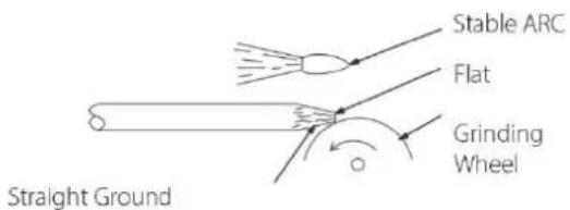
Figure 62
Wrong Tungsten Preparation = Wandering ARC

Figure 63
Pointing the Tungsten Electrode
The electrode should be pointed according to the welding current.
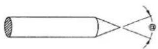
Figure 64
| Electrode Angles | |
| Angle @ | Range of Current (Amps) |
| 30° | 0 – 30 |
| 60-90° | 30 -120 |
| 90-120° | 120 - 250 |
| 120° | ≥250 |
Table 21
13.1.3 Shielding Gas for TIG Welding
| Shielding Gas Selection | |
| Alloy | Shielding Gas |
| Carbon Steel | Welding Argon |
| Stainless Steel | |
| Nickel Alloy | |
| Copper | |
| Titanium | |
Table 22
13.1.4 Typical TIG Welding Settings
| TIG Welding Settings For Steel | ||||||
| Metal Thickness | DC Current (Amps) | Tungsten Electrode Diameter | Filler Rod Diameter (if required) | Argon Gas Flow Rate L/min | Joint Type | |
| Mild Steel | Stainless Steel | |||||
| 1.2mm (0.045") | 45-55 | 30-45 | 1.0mm (0.040") | 1.6mm (1/16") | 5 – 7 | Butt/ Corner |
| 50-60 | 35-50 | Lap / Fillet | ||||
| 1.6mm (1/16") | 60-70 | 40-60 | 1.6mm (1/16") | 1.6mm (1/16") | 7 | Butt/ Corner |
| 70-90 | 50-70 | Lap / Fillet | ||||
| 3.2mm (1/8") | 80-100 | 65-85 | 1.6mm (1/16") | 2.4mm (3/32") | 7 | Butt/ Corner |
| 90-115 | 90-110 | Lap / Fillet | ||||
Table 23
13.2 TIG Welding Troubleshooting
| Troubleshooting - TIG Weld quality | ||
| Fault | Cause | Remedy |
| Excessive bead build up or poor penetration or poor fusion at edges of weld | Welding current is too low. | Increase weld current and/or faulty joint preparation |
| Weld bead too wide and flat or undercut at edges of weld or excessive burn through | Welding current is too high. | Decrease weld current. |
| Weld bead too small or insufficient penetration or ripples in bead are widely spaced apart. | Travel speed too fast. | Decrease weld current. |
| Weld bead too wide or excessive bead build up or excessive penetration in butt joint. | Travel speed too fast. | Increase travel speed. |
| Uneven leg length in fillet joint | Wrong placement of filler rod. | Re-position rod. |
| Electrode melts or oxidises when an arc in struck | Torch lead connected to positive welding terminal. | Connect torch lead to negative welding terminal. |
| No gas flowing to welding region. | Check the gas lines for kinks or breaks and gas cylinder contents. | |
| Torch is clogged with dust or dirt. | Clean torch. | |
| Gas hose is cut. | Replace gas hose. | |
| Gas passage contains impurities. | Disconnect gas hose from the rear of Power Source then raise gas pressure and blow out impurities. | |
| Gas regulator turned off. | Turn on. | |
| Torch electrode is too small for the welding current. | Increase electrode diameter or reduce the welding current. | |
| Dirty weld pool | Electrode contaminated by contact with work piece or filler rod material. | Clean the electrode by grinding off any contaminates. |
| Work piece surface has foreign material on it. | Clean surface. | |
| Gas contaminated with air. | Check gas lines for cuts and loose fitting or change gas cylinder. | |
| Poor weld pool | Inadequate shielding gas. | Increase gas flow or check gas line for gas flow problems. |
| Arc start is not smooth. | Tungsten electrode is too large for the welding current. | Select the right size electrode. |
| The wrong electrode is being used for the welding job. | Select the right electrode type. | |
| Gas flow rate is too high. | Select the right rate for the welding job. | |
| Incorrect shielding gas is being used. | Select the right shielding gas. | |
| Poor Work Lead/Clamp connection to work piece. | Improve connection to work piece. | |
| Arc flutters during TIG welding. | Tungsten electrode is too large for the welding current. | Select the right size electrode. |
Table 24
14 KNOWLEDGE & RESOURCES
Please refer to Weldclass website www.weldclass.com.au for more information.
15 SAFETY
15.1 Store and Retain this Manual
Retain this manual for the safety warnings and precautions, assembly, operating, inspection, maintenance and cleaning procedures. Write the product's serial number into the NOTES section at the rear, and keep this manual and the receipt in a safe and dry place for future reference.
15.2 Important Safety Information
Failure to follow the warnings and instructions may result in electric shock, fire, serious injury and/or death. Save all warnings and instructions for future reference.
This is the safety alert symbol to alert you to potential personal injury hazards:

Obey all safety messages that follow this symbol to avoid possible injury or death.

DANGER! indicates a hazardous situation which, if not avoided, will result in death or serious injury.

WARNING! indicates a hazardous situation which, if not avoided, could result in death or serious

CAUTION, used with the safety alert symbol, indicates a hazardous situation which, if not avoided, result in minor or moderate injury.
NOTE, used to address practices not related to personal injury.
CAUTION, without the safety alert symbol, is used to address practices not related to personal injury.
15.3 Welding Operation
- Maintain labels and nameplates on the welder. These carry important information. If unreadable or missing, contact Weldclass for a replacement.
- Avoid unintentional starting. Make sure the welder is setup correctly and you are prepared to begin work before turning on the welder.
-
Unplug before performing maintenance. Always unplug the welder from its electrical outlet before performing any inspection, maintenance, or cleaning procedures.
-
Never leave the welder unattended while energised. Turn power off before leaving the welder unattended.
- Do not touch live electrical parts. Wear dry, insulating gloves. Do not touch the electrode or the conductor tong with bare hands. Do not wear wet or damaged gloves.
- Protect yourself from electric shock. Do not use the welder outdoors. Insulate yourself from the work piece and the ground. Use non-flammable, dry insulating material if possible, or use dry rubber mats, dry wood or plywood, or other dry insulating material large enough to cover the area of contact with the work or the ground.
- Avoid inhaling fume. Some fume created by welding contain chemicals known to cause cancer, birth defects or other harm. Your risk from these exposures varies, depending on how often you do this type of work. To reduce your exposure to these chemicals, work in a well-ventilated area, and work with approved safety equipment, such as dust masks that are specially designed to filter out microscopic particles.
- People with pacemakers should consult their physician(s) before using this machine.

WARNING! Electromagnetic fields in close proximity to a heart pacemaker cause interference, or failure of the pacemaker. The use of a Welder is NOT RECOMMENDED for pacemaker wearers. Consult your doctor.
- Ensure that the unit is placed on a stable location before use.

WARNING! If this unit falls while plugged in, severe injury, electric shock, or fire may result.
- Transportation Methods. Lift unit with the handles provided, or use a handcart or similar device of adequate capacity. If using a fork lift vehicle, secure the unit to a skid before transporting.

CAUTION! Disconnect input power conductors from de-energized supply line before moving the welding power source.
- Exercise good work practices. The warnings, precautions, and instructions discussed in this instruction manual cannot cover all possible conditions and situations that may occur. It must be understood by the operator that common sense and caution are factors which cannot be built into this product, but must be considered by the operator.
- Do not use this machine for pipe thawing. This machine was not designed for pipe thawing and will be a significant electrical & heat hazard if attempt is made to use for thawing pipe.
15.4 Welding Safety Instructions & Warnings

WARNING! Protect yourself and others from possible serious injury or death.
Keep children away. Read the operating/Instruction manual before installing, operating or servicing this equipment. Have all installation, operation, maintenance, and repair work performed by qualified people.
If an operator does not strictly observe all safety rules and take precautionary actions, welding products and welding processes can cause serious injury or death, or damage to other equipment or property.
Safe practices have developed from past experience in the use of welding and cutting. These practices must be learned through study and training before using this equipment. Some of these practices apply to equipment connected to power lines; other practices apply to engine driven equipment. Anyone not having extensive training in welding and cutting practices should not attempt to weld.
Safe practices are outlined in the Australian Standard AS 1674.2 entitled: Safety in Welding and European Standard EN60974-1 entitled: Safety in welding and allied processes.

WARNING! Only use safety equipment that has been approved by an
appropriate standards agency. Unapproved safety equipment may not provide adequate protection. Eye and breathing protection must be AS/NZS compliant for the specific hazards in the work area.

DANGER! Always wear AS/NZS compliant safety glasses and full face shielded with appropriate filter shade number. (Refer Filter Table on page 17.)

CAUTION! Heavy-duty work gloves, non-skid safety shoes and hearing section used for appropriate conditions will reduce personal injuries.

CAUTION! Have the equipment serviced by a qualified repair person using cal replacement parts. This will ensure that the safety of the power tool is maintained.
15.4.1 Personal Safety

CAUTION! Keep the work area well lit. Make sure there is adequate space lying the work area. Always keep the work area free of obstructions, grease, and other debris. Do not use equipment in areas near flammable chemicals, dust, and vapours. Do not use this product in a damp or wet location.
- Stay alert, watch what you are doing and use common sense when operating equipment. Do not use a tool while you are tired or under the influence of drugs, alcohol or medication. A moment of distraction when operating equipment may result in serious personal injury.
- Do not overreach. Keep proper footing and balance at all times. This enables better control of the power tool in unexpected situations.
15.4.2 Arc Rays can Burn Eyes and Skin

CAUTION! Arc rays from the welding process produce intense heat and strong ultraviolet rays that can burn eyes and skin.
- Use a Welding Helmet or Welding Face Shield fitted with a proper shade filter (refer AS 60974-1, AS/NZS 1337.1 and AS/NZS 1338.1 Safety Standards) to protect your face and eyes when welding or watching. (See Filter Table on Page17).
- Wear approved safety glasses. Side shields are recommended.
- Use protective screens or barriers to protect others from flash and glare; warn others not to watch the arc.
- Wear protective clothing made from durable, flame-resistant material (wool and leather) and foot safety protection.
- Never wear contact lenses while welding.
15.4.3 Noise Can Damage Hearing

CAUTION! Noise from some processes can damage hearing. Use AS/NZS compliant ear plugs or ear muffs if the noise level is high.
15.4.4 Work Environment Safety

DANGER! Remove any combustible material from the work area.
- When possible, move the work to a location well away from combustible materials. If relocation is not possible, protect the combustibles with a cover made of fire resistant material.
- Remove or make safe all combustible materials for a radius of 10 metres around the work area. Use a fire resistant material to cover or block all doorways, windows, cracks, and other openings.
- Enclose the work area with portable fire resistant screens. Protect combustible walls, ceilings, floors, etc., from sparks and heat with fire resistant covers.
- If working on a metal wall, ceiling, etc., prevent ignition of combustibles on the other side by moving the combustibles to a safe location. If relocation of combustibles is not possible, designate someone to serve as a fire watch, equipped with a fire extinguisher, during the welding process and well after the welding is completed.
- Do not weld or cut on materials having a combustible coating or combustible internal structure, as in walls or ceilings, without an approved method for eliminating the hazard.
- After welding, make a thorough examination for evidence of fire. Be aware that visible smoke or flame may not be present for some time after the fire has started. Do not weld or cut in atmospheres containing dangerously reactive or flammable gases, vapours, liquids, and dust. Provide adequate ventilation in work areas to prevent accumulation of flammable gases, vapours, and dust.
- Do not apply heat to a container that has held an unknown substance or a combustible material whose contents, when heated, can produce flammable or explosive vapours. Clean and purge containers before applying heat. Vent closed containers, including castings, before preheating, welding, or cutting.
15.4.5 Electricity Can Kill

DANGER! Touching live electrical parts can cause fatal shocks or severe burns.
The electrode and work circuit is electrically live whenever the output is on.
The input power circuit and machine internal circuits are also live when power is on. In semiautomatic or automatic wire welding, the wire, wire reel, drive roll housing, and all metal parts touching the welding wire are electrically live. Incorrectly installed or improperly grounded equipment is a hazard.
- Do not touch live electrical parts.
- Wear dry, hole-free insulating gloves and body protection.
- Insulate yourself from the work and the ground using dry insulating mats or covers.
-
Disconnect input power before installing or servicing this equipment. Lock input power, disconnect switch open, or remove line fuses so power cannot be turned on accidentally.
-
Properly install and ground this equipment according to national, state, and local codes.
- Turn off all equipment when not in use. Disconnect power to equipment if it will be left unattended or out of service.
- Use fully insulated electrode holders. Never dip the holder in water to cool it or lay it down on the ground or the work surface. Do not touch holders connected to two welding machines at the same time or touch other people with the holder or electrode.
- Do not use worn, damaged, undersized, or poorly spliced cables.
- Do not wrap cables around your body.
- Connect work piece to a good electrical ground.
- Do not touch the electrode while in contact with the work (ground) circuit.
- Use only well-maintained equipment. Repair or replace damaged parts as soon as practical.
- In confined spaces or damp locations, do not use a welder with AC output unless equipped with a voltage reducer.
Arc rays from the welding process produce intense heat and strong ultraviolet rays that can burn eyes and skin. Use the following table to select the appropriate shade number for a Welding Helmet or Welding Face Shield.
| Recommended Protection Fillers For Electric Welding | ||
| Welding Process / Application | Approximate Range of Welding Current in Amps | Minimum Shade Number of Filter Lens |
| Stick (MMA) | Up to 100 | 8 |
| 100 to 200 | 10 | |
| MIG(other than Aluminum and Stainless Steel) | Up to 150 | 10 |
| 150 to 250 | 11 | |
| MIGof Aluminum and Stainless Steel | Up to 250 | 12 |
| MIGFlux-Cored Arc Welding (FCAW) – with or without Shielding Gas | Up to 300 | 10 |
| TIG | Up to 100 | 10 |
| 100 to 200 | 11 | |
Table 25
15.4.6 Fumes And Gases

WARNING! Welding produces fumes and gases. Breathing these fumes and gases can be hazardous to your health.
- Keep your head out of the fumes. Do not breathe the fumes.
- If inside, ventilate the area and/or use an exhaust at the arc to remove welding fumes and gases.
- If ventilation is poor, use an approved supplied-air respirator (PAPR).
- Read the Safety Data Sheets (SDS) and the manufacturer's instruction for the metals, consumables, coatings, and cleaners.
-
Work in a confined space only if it is well ventilated, or while wearing an air-supplied respirator. Shielding gases used for welding can displace air causing injury or death. Be sure the breathing air is safe.
-
Do not weld in locations near degreasing, cleaning, or spraying operations. The heat and rays of the arc can react with vapours to form highly toxic and irritating gases.
- Do not weld on coated metals, such as galvanized, lead, or cadmium plated steel, unless the coating is removed from the weld area, the area is well ventilated, and if necessary, while wearing an air-supplied respirator. The coatings and any metals containing these elements can give off toxic fumes if welded.
15.4.7 Fire & Explosive Risks

WARNING! Sparks and spatter fly off from the welding arc. The flying sparks hot metal, weld spatter, work piece, and hot equipment can cause fires and burns.
Accidental contact of electrode or welding wire to metal objects can cause sparks, overheating, or fire.
- Protect yourself and others from flying sparks and hot metal.
- Do not weld where flying sparks can strike flammable material.
- Remove all flammables within 10m of the welding site.
- Be alert that welding sparks and hot materials from welding can easily go through small cracks and openings to adjacent areas.
- Watch for fire, and keep a fire extinguisher nearby.
- Be aware that welding on a ceiling, floor, bulkhead, or partition can cause fire on the hidden side.
- Do not weld on closed containers such as tanks or drums.
- Connect the work lead/clamp to the job as close to the welding area as practical to prevent welding current from traveling long, possibly unknown paths and causing electric shock and fire hazards.
- Do not use a welder to thaw frozen pipes.
- Remove the stick electrode from the holder or cut off the welding wire at the contact tip when not in use.
15.4.8 Sparks & Hot Metal

WARNING! Chipping and grinding causes flying metal, and as welds cool they can throw off slag.
- Wear an AS/NZS approved face shield or safety goggles. Side shields are recommended.
- Wear appropriate safety equipment to protect the skin and body.
15.4.9 Gas Cylinders

WARNING! Gas cylinders contain gas under high pressure. If damaged, a an explode. Since gas cylinders are normally part of the welding process, be sure to treat them carefully.
- Protect compressed gas cylinders from excessive heat, mechanical shocks, and arcs.
- Install and secure cylinders in an upright position by chaining them to a stationary support or equipment cylinder rack to prevent falling or tipping.
- Keep cylinders away from any welding or other electrical circuits.
- Never allow a welding electrode to touch any cylinder.
- Use appropriate shielding gas, regulators, hoses, and fittings designed for the specific application; maintain them and their associated parts in good condition.
- Turn your face away from the valve outlet when opening the cylinder valve.
16 WARRANTY
16.1 Warranty Information
For full details on warranty period and terms and conditions, go to www.weldclass.com.au/WarrantyInfo

natural_image
Abstract geometric pattern with radial lines and a central star (no text or symbols)Weldclass
Be Outstanding
www.Weldclass.com.au
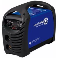


- Weldclass
- Be Outstanding
- Weldforce 155M Weldforce 175MST
- OPERATING INSTRUCTIONS
- IMPORTANT!
- Congratulations & thank you for choosing Weldclass!
- Register Your Warranty Now
- Satisfaction Guarantee
- Using Gasless MIG Wire?
- CONTENTS
- KNOW YOUR MACHINE
- Machine Front
- Machine Rear
- Control Panel
- Symbols chart
- CONTROLS EXPLAINED
- Weld Process Selection (Weldforce 175MST only)
- MIG/MAG Process:
- MMA (Stick) Process:
- TIG Process:
- Welding Power Output Control
- Inductance Control (MIG/MAG only)
- Arc Force Adjustment (MMA/Stick only) (Weldforce 175MST only)
- Error/Over Temperature Indicator Light
- POWER SUPPLY
- Electrical Connection
- Extension Leads
- Generator Use
- Generator Size
- Generator Quality & Warranty Limitations
- 3 Golden Rules of Generator use
- OPERATING ENVIRONMENT
- Location
- Ventilation
- BASIC OPERATION
- MIG Welding
- Fitting Wire Spool
- Loading Wire Feeder
- Gasless Welding Setup
- Weldforce 155M
- Weldforce 175MST
- Gas MIG Welding Setup
- Additional Setup for MIG welding with Aluminium (Weldforce 175MST only)
- Settings for MIG Welding
- Drive Rollers & Torch Liners for different Wires
- Stick (MMA) Welding Operation (Weldforce 175MST only)
- Lift TIG Operation (Weldforce 175MST only)
- ACCESSORIES, SPARE PARTS & CIRCUIT DIAGRAMS
- MIG Torch and Spares for Weldforce 155M:
- MIG Torch and Spares for Weldforce 175M:
- TIG Torch and Spares (Optional Extra for Weldforce 175MST only):
- Optional Accessories
- Drive Rollers
- Machine Spare Parts:
- Keep your Welding Machine in Top Condition
- Storing the Welder
- GENERAL GUIDE TO WELDING
- Duty Cycle Rating
- Choosing a Welding Process – MIG, Stick or TIG?
- The Stick (MMA) Process
- Description
- Process
- Advantages
- Limitations
- Materials
- The TIG Process
- Description
- Process
- Advantages
- Limitations
- Materials
- The MIG Process
- Description
- Process
- Advantages
- Limitations
- Materials
- Joint Preparations
- MIG BASIC WELDING GUIDE
- MIG Basic Welding Techniques
- Gas Metal Arc Welding (GMAW)
- Flux Cored Arc Welding (FCAW)
- Position of MIG Torch
- Distance from the MIG Torch Nozzle to the Work Piece
- Travel Speed
- MIG Welding (GMAW) Variables
- Preselected Variables
- Primary Adjustable Variables
- Secondary Adjustable Variables
- Establishing the Arc and Making Weld Beads
- MIG Output Settings
- Changing to a different welding wire
- Welding wire Size Selection
- MIG Welding Troubleshooting
- Porosity Problems
- Figure 39
- Fault
- Cause
- Wire Feed Problems
- TOP TIPS - Wire Jam Troubleshooting
- Weld Quality Problems
- STICK (MMA) BASIC WELDING GUIDE
- Size of Electrodes
- Storage of Electrodes
- Electrode Polarity
- Effects of Stick (MMA) Welding on Various Materials
- High Tensile and Alloy Steels
- Manganese Steels
- Cast Iron
- Types of Electrodes
- MILD STEEL:
- CAST IRON:
- STAINLESS STEEL:
- Suggested Settings for Typical Stick (MMA) Applications
- MMA Welding Techniques
- A Word for Beginners
- The Welder
- Striking the Arc
- Arc Length
- Rate of Travel
- Making Welded Joints
- Butt Welds
- Fillet Welds
- Vertical Welds
- Vertical Up
- Vertical Down
- Overhead Welds
- MMA (Stick) Troubleshooting
- TIG BASIC WELDING GUIDE
- TIG Electrode Selection and Preparation
- Electrode Polarity
- Preparing Tungsten for DC Electrode Negative (DCEN) Welding
- Ideal Tungsten Preparation = Stable ARC
- Wrong Tungsten Preparation = Wandering ARC
- Pointing the Tungsten Electrode
- Shielding Gas for TIG Welding
- Typical TIG Welding Settings
- KNOWLEDGE & RESOURCES
- SAFETY
- Store and Retain this Manual
- Important Safety Information
- Welding Operation
- Welding Safety Instructions & Warnings
- Personal Safety
- Arc Rays can Burn Eyes and Skin
- Noise Can Damage Hearing
- Work Environment Safety
- Electricity Can Kill
- Fumes And Gases
- Fire & Explosive Risks
- Sparks & Hot Metal
- Gas Cylinders
- WARRANTY
- Warranty Information
Brand : Weldclass
Model : Weldforce 155M
Category : Soldering iron