
KCV2404-W - Heating KING - Free user manual and instructions
Find the device manual for free KCV2404-W KING in PDF.


| Product Type | Electric Fan Heater |
| Brand | King |
| Model | KCV2404-W |
| Dimensions (HxWxD) | 250 x 180 x 120 mm |
| Weight | 1.8 kg |
| Power Supply | 220-240 V ~ 50/60 Hz |
| Rated Power | 2000 W |
| Heating Type | Ceramic PTC |
| Temperature Control | Adjustable Thermostat |
| Fan Speed | 2 Levels (Low/High) |
| Oscillation | Yes, 70° Wide Angle |
| Safety Features | Overheat Protection, Tip-over Switch |
| Housing Material | ABS Plastic |
| Noise Level | < 45 dB |
| Room Coverage | Up to 25 m² |
| Cleaning | Wipe with a soft, dry cloth. Do not immerse in water. |
| Spare Parts Availability | Contact King customer service |
| Included Accessories | User Manual |
| Energy Efficiency Class | Class A |
Frequently Asked Questions - KCV2404-W KING
User questions about KCV2404-W KING
0 question about this device. Answer the ones you know or ask your own.
Ask a new question about this device
Download the instructions for your Heating in PDF format for free! Find your manual KCV2404-W - KING and take your electronic device back in hand. On this page are published all the documents necessary for the use of your device. KCV2404-W by KING.
USER MANUAL KCV2404-W KING
INSTALLATION INSTRUCTIONS

king
KCV SERIES Cove Heater

DANGER

ELECTRIC SHOCK OR FIRE HAZARD
READ ALL WIRE SIZING, VOLTAGE REQUIREMENTS AND SAFETY DATA TO AVOID PROPERTY DAMAGE AND PERSONAL INJURY


WARNING

It is extremely important to verify the electrical power supply is the same voltage as the heater being installed. 240 and 120 Volt heaters are not interchangeable. Powering a 240 Volt unit with 120 Volt supply wires will reduce heater output by approximately 75%. Powering a 120 Volt unit with 240 Volt supply wires will destroy the heater and voids all guarantee and warranties.
CAUTION: Turn off power source supplying heater before attempting any installation, maintenance or repairs. Lock or tag circuit breaker/fuse panel door. Failure to do so could result in serious electrical shock, burns or possible death.
WARNINGS: To insure proper operation of this heater it should be a minimum of 6 feet above the floor and no closer than 2½" below drywall ceiling (6" vinyl or drop ceilings). Draperies should clear the front and the top of this heater by 6". Draperies hung below the heater should have a 2½" clearance. Do not block the heater in any manner. Never paint the heater.

MAINTENANCE & WARRANTY
Following the guidelines herein listed will result in a maintenance-free heater. There are no moving parts or motors to maintain. Periodic dusting of the front panel is all that is suggested.
The KCV Cove Heater carries a (2) warranty form date of installation. Please refer to the manufacturer's warranty statement for further information.
GENERAL INFORMATION
Cove heaters are completely assembled and pre-wired. To prepare the heater for installation, carefully check the voltage to be used is the same as stated on the rating nameplate. Operating voltage can not exceed 5% of nameplate voltage. Operating heater above listed voltage ratings voids all gaurantees and warranties.


SAVE THESE INSTRUCTIONS
INSTALLATION INSTRUCTIONS
Following are some general guidelines:
- Do not recess this cove heater.
- Disconnect power at main panel.
-
Make certain all wiring is in accordance with all local codes and units are properly grounded.
-
Voltage rating of heater should be the same as supply load.
-
Do not install the heater on vinyl wall coverings.
-
Remove heater from carton. Disassemble the aluminum heating panel from the back support frame. Remove knock out in junction box for electrical supply connection. See Figure A & B.
- To install the back support frame on the wall, locate the studs in the wall and use existing mounting holes or pre-drill 3/16" holes as needed. Use appropriate fasteners to securely mount to wall. See Figure B.
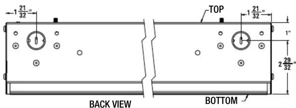

Fig. B

natural_image
Technical line drawing of two mechanical components with mounting holes and a labeled top view (no text or symbols on the diagram itself)Fig. A
-
Temporarily hang the aluminum heating panel from the top lip of both junction boxes. This will support the heater while the electrical connections are made and allow one person to wire the heater without having to hold the panel at the same time. See Figure C.
-
Connect the supply cable grounding wire to the green wire pigtail in wiring compartment.
-
Follow the desired wiring diagram, to connect the power supply to the heater using approved wire nuts.

Fig. C
Instructions for left or right side wiring
- Heater can be wired from either side - wire one side only.
Caution: Power wires should be connected on one side only.
In the opposite junction box, connect the white and black element wires together using an approved wire nut. See Figures D and E.
SAVE THESE INSTRUCTIONS

- After wiring is complete, carefully press the electrical wires into the junction box, making sure not to pinch any wires between the junction box and the heating panel.
- Install the end caps: Push the bottom edge of the aluminum heating panel towards the back panel, while installing the end caps and lightly tighten the 2 screws to secure it. Do Not Overtighten, as the aluminum heating panel will expand and contract during heating, requiring it to move freely. See Figure F.


CAUTION

File #E41422
The heater should not be covered or blocked in any manner.
SAVE THESE INSTRUCTIONS

Smart Heating Solutions
Brand : KING
Model : KCV2404-W
Category : Heating