
Pro Convert HDMI 4K Plus - Audio/video converter Magewell - Free user manual and instructions
Find the device manual for free Pro Convert HDMI 4K Plus Magewell in PDF.


| Product Type | Audio/Video Converter (Decoder) |
| Brand | Magewell |
| Model | Pro Convert HDMI 4K Plus |
| Input Stream Formats | NDI, RTSP, HTTP, HLS, RTMP Pull/Push, MPEG-TS over UDP/SRT/RTP (H.264/H.265) |
| Output Interface | HDMI 4K |
| Maximum Output Resolution | 4096x2160p at 60 fps (4K) |
| Audio Support | Embedded audio decoding, up to 8 channels |
| Power Supply | 5V DC via USB (2.1A) or PoE (Power over Ethernet) |
| Network Connection | Gigabit Ethernet |
| Control Methods | Web-based UI, on-device buttons, OSD menu, optional keyboard/mouse |
| Low Latency | Minimum ~50 ms (1080p60, buffer 20 ms) |
| Video Processing | Hardware up/down/cross-conversion, deinterlacing, aspect ratio conversion |
| Additional Features | OSD overlay, audio metering, PTZ control (NDI sources), Ethernet over USB |
| Maintenance | Keep device free from dust; avoid high-temperature environments |
| Safety Warnings | Use correct power adapter; avoid short circuits; do not expose to moisture |
| Spare Parts / Repairability | Contact Magewell support for replacement accessories (power adapter, USB cable) |
| Warranty | 2 years for device, 1 year for accessories |
| Dimensions | Approx. 100 x 100 x 25 mm (estimated) |
| Weight | Approx. 200 g (estimated) |
Frequently Asked Questions - Pro Convert HDMI 4K Plus Magewell
User questions about Pro Convert HDMI 4K Plus Magewell
0 question about this device. Answer the ones you know or ask your own.
Ask a new question about this device
Download the instructions for your Audio/video converter in PDF format for free! Find your manual Pro Convert HDMI 4K Plus - Magewell and take your electronic device back in hand. On this page are published all the documents necessary for the use of your device. Pro Convert HDMI 4K Plus by Magewell.
USER MANUAL Pro Convert HDMI 4K Plus Magewell
Pro Convert Decoder Family
User Manual, Reference and FAQ
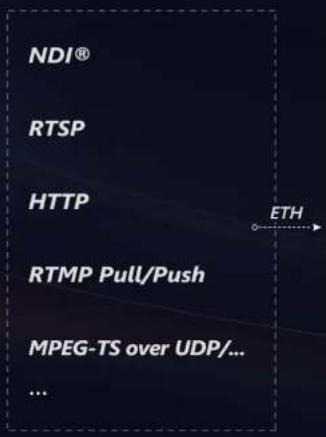
TABLE OF CONTENTS
| Getting Started | 03 |
| 03 | |
| 03 | |
| 04 | |
| Installation | 05 |
| 05 | |
| 06 | |
| 13 | |
| Web UI Configuration | 16 |
| 16 | |
| 20 | |
| 21 | |
| 26 | |
| 28 | |
| 34 | |
| 37 | |
| 38 |
| OSD Menu Configuration | 58 |
| 59 | |
| 60 | |
| 62 | |
| 63 | |
| 69 | |
| 70 | |
| 72 | |
| 73 | |
| FAQ | 74 |
| Support | 85 |
| Warranty | 86 |
Getting Started
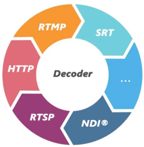
flowchart
graph TD
    A["Decoder"] --> B["RTMP"]
    A --> C["SRT"]
    A --> D["HTTP"]
    A --> E["RTSP"]
    A --> F["NDI®"]
Overview
Pro Convert ^™ family decoders convert live NDI, H.264 and H.265 streams into high-quality outputs for connection to baseband devices such as monitors and projectors. The low-latency decoder simplifies the use of NewTek's popular media-over-IP technology in applications such as digital signage and video walls.
The ultra-compact Pro Convert devices are ideal for both in-studio and portable field use. The decoder features DHCP-based automatic network configuration, while a browser-based interface provides access to status monitoring and advanced features such as hardware-based up/down/cross-conversion. On-device buttons also enable users to select source content and match the output format to their target display without requiring a computer.
Key Features
• Support for decoding streams of NDI, RTSP, HTTP, HLS, RTMP Pull/Push and MPEG-TS over UDP/SRT/RTP in H.264 or H.265 format.
• Support for decoding embedded audio.
• Support for PoE (Power over Ethernet).
- Support for plug-and-play.
• Support for Ethernet over USB.
- Support for web-based UI remote control and on-device control buttons.
System Requirements
Network
- Gigabit Ethernet
Supported Web Browser for the Web UI
• Google Chrome version 49 and above
• Microsoft Internet Explorer 11
- Microsoft Edge
- Mozilla Firefox version 61 and above
• Apple Safari 11.1 and above
• Opera 55.0.2994.44 and above
Pro Convert Decoder
This User Guide is intended to provide guidance to use the Pro Convert decoders, including:
• Pro Convert for NDI® to HDMI 4K
• Pro Convert for NDI® to HDMI
• Pro Convert for NDI® to AIO
• Pro Convert for NDI® to SDI
• Pro Convert H.26x to HDMI 4K
• Pro Convert H.26x to HDMI
• Pro Convert H.26x to SDI
Magewell keeps releasing best decoders for you. The latest product information refers to Pro Convert Decoder Family.
Installation
Safety Information
Electrical Safety
- Seek professional assistance before using an adapter or extension cord. These devices could interrupt the grounding circuit.
• Make sure that you are using the correct power adapter for the local voltage. If you are not sure about the voltage of the electrical outlet you are using, contact your local power company.
• If the power adapter is broken, do not try to fix it by yourself. Contact a qualified service technician or your retailer for help.
Operation Safety
- Before using the product, make sure all cables are correctly connected and the power cables are not damaged. If you notice any damage, contact your dealer immediately.
• To avoid short circuits, keep paper clips, screws, and staples away from connectors, slots, sockets and circuitry. - Avoid dust, humidity, and temperature extremes. Do not place the product in any area where it may become wet.
- Place the product on a stable surface.
• If you encounter technical problems with the product, contact your dealer or the Magewell Support Team via support@magewell.net.
Interfaces & Indicators
Pro Convert for NDI® to HDMI
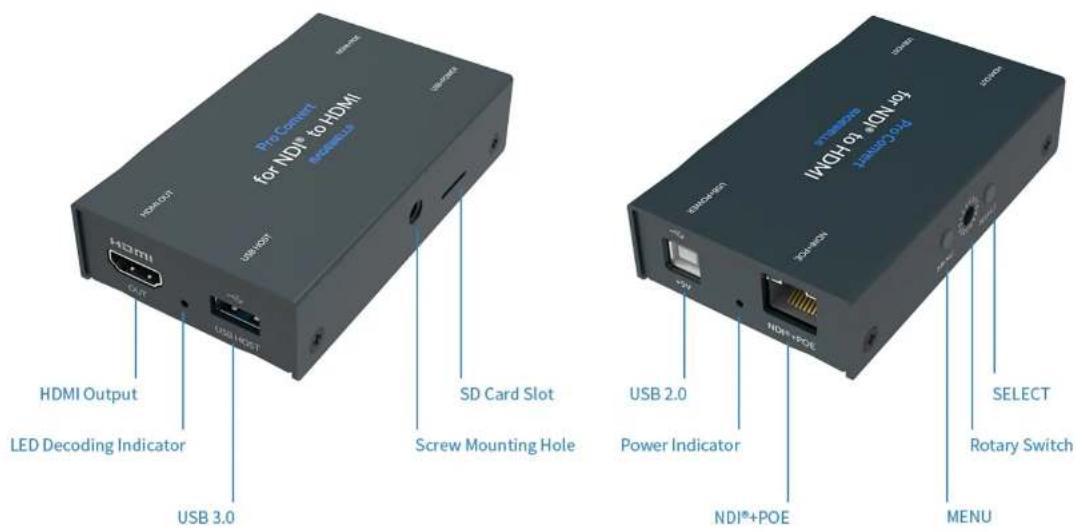
Note: The SD card function is not available currently.
Pro Convert for NDI® to HDMI 4K
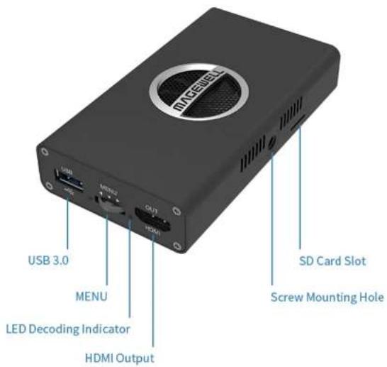
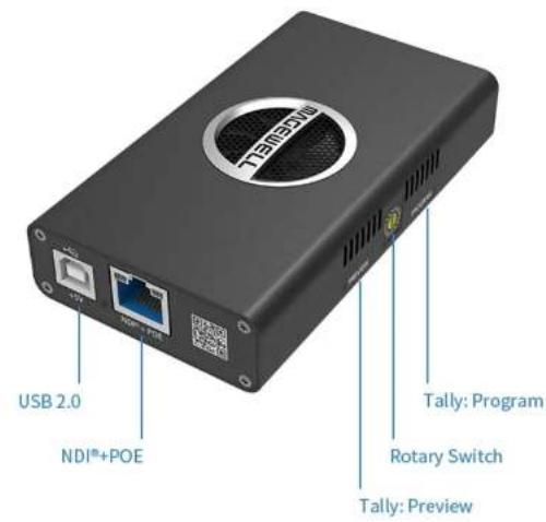
Note: The SD card function is not available currently.
Pro Convert H.26x to HDMI
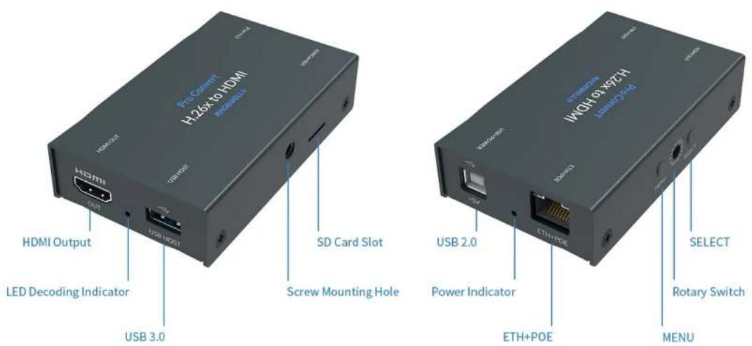
Note: The SD card function is not available currently.
Pro Convert H.26x to HDMI 4K
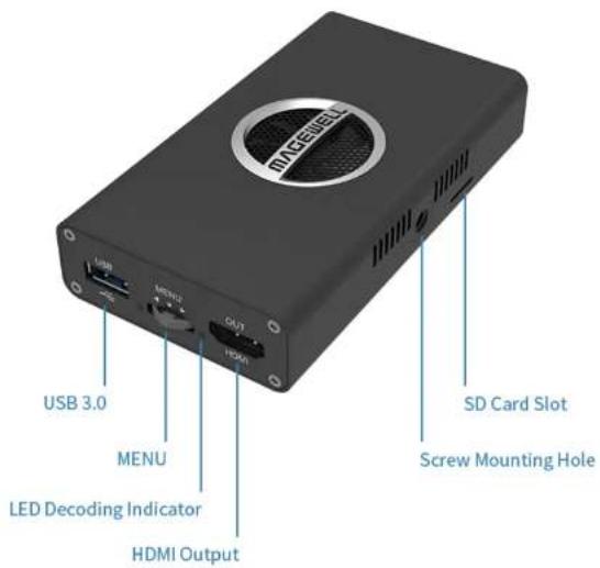
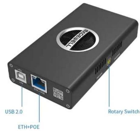
Note: The SD card function is not available currently.
Pro Convert for NDI® to SDI
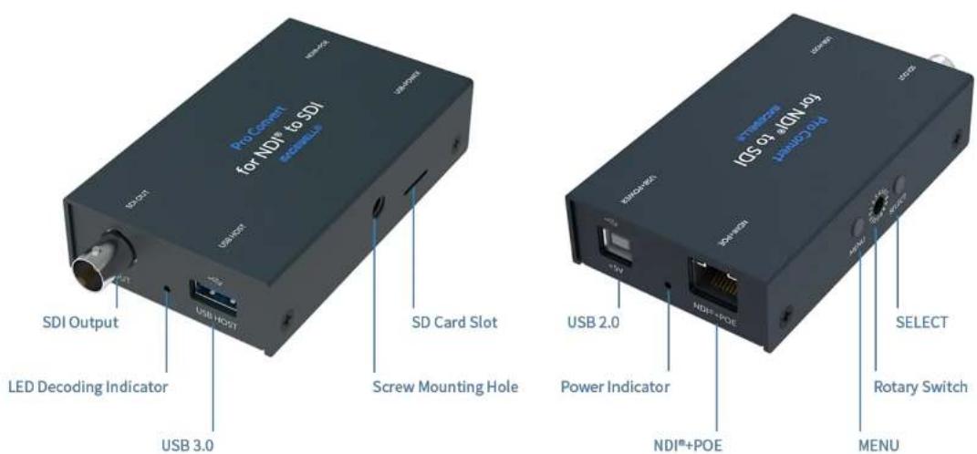
Note: The SD card function is not available currently.
Pro Convert H.26x to SDI
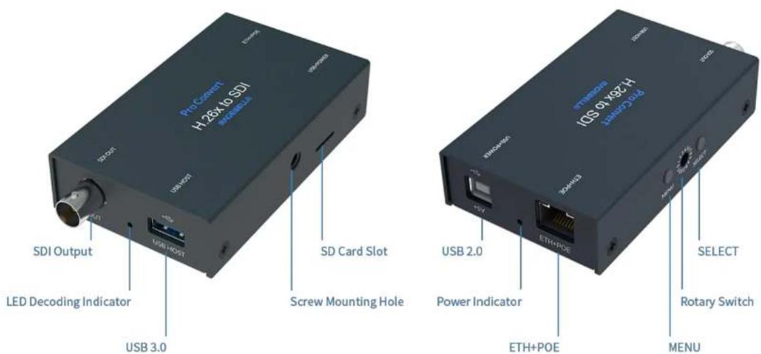
Note: The SD card function is not available currently.
Pro Convert for NDI® to AIO
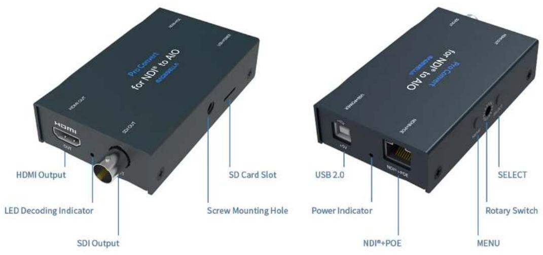
Note: The SD card function is not available currently.
Connections
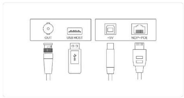
Interfaces and cables varies according to signal supported by Pro Convert.
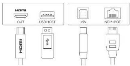
Figure 1. Pro Convert for NDT to HDMI
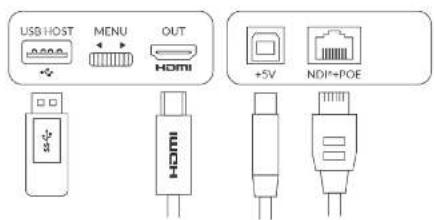
Figure 2. Pro Convert for NDT to HDMI 4K
Cable your device for power, network connectivity, output and device control.
- Plug in the USB cable to the power interface.
- For power supply: connect the other end of the USB cable to the power adapter.
- For Ethernet over USB (RNDIS/ECM): connect the other end of the USB cable to your computer.
- Plug in the Ethernet cable to the network interface.
- For PoE: connect the other end of the Ethernet cable to a PoE switch or a PoE adapter for power and Ethernet connection.
-
For Ethernet connection: to ensure high speed transmission, it is recommended to connect the Pro Convert unit to a gigabit network.
-
Plug in the HDMI or/and SDI cable by the interface type to connect the AV equipment(s), such as a monitor, a video switcher, a video capture card, or a projector.
- AV facility loaded with a smart OS is not recommended if low latency matters.
- Connect a wired or wireless keyboard or mouse to the USB HOST interface to make it more convenient to control advanced settings without requiring a computer.
- AIO product does not have the USB interface for peripherals connection.
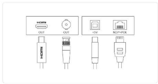
Figure 3 Pro Convert for NDI to AIO Figure 4 Pro Convert for NDI to SDI
粒
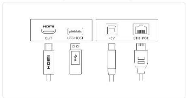
Figure 5. Pro Convert H.26x to HDMI Figure 6. Pro Convert H.26x to HDMI 4K
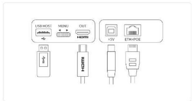
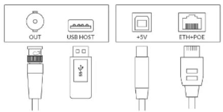
Figure 7. Pro Convert H.26x to SDI
Web UI Configuration
Pro Convert allows you to control your device via a web-based user interface. With the Web UI, you can monitor the device's working status, input signal status, and custom parameters for your sessions. We take the Web UI of Pro Convert for NDI® to HDMI as an example to describe its functionalities.
Accessing the Web UI
If you know your device's IP address, type it into your web browser to display the Web UI. Alternatively, you can access the Web UI in one of the following ways.
Solution 1: For Windows7/8/8.1/10 users, you can find and access your Pro Convert device as a Network device in a File Explorer window.
Solution 2: Using the Ethernet over USB function.
Solution 3: Using the on-screen menu Options.
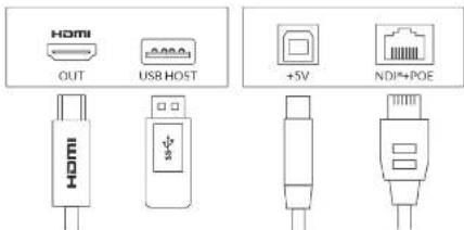
Figure 1 Connections
Solution 1: using Windows File Explorer
This method is available for Windows7/8/8.1/10 users.
Step 1 Connect your decoder via Ethernet and power it up as shown on the left figure.
Open a File Explorer window in one of the following ways.Step 2
- Click on the Start Button and find File Explorer in the Start menu.
- Press the Windows logo key E.
- Select the folder icon on the taskbar.
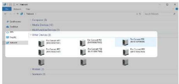
Figure 2 Find your Pro Convert device in the Network > Other Devices section
Step 3 Select the Network at the bottom of the list of items on the left side of the File Explorer.
Turn on the network discovery function if prompted. Step 4
Step 5 Find your Pro Convert device in the Other Devices section, where it will be shown as "Pro Convert + #board index + (serial number)".
- The serial number (marked on your device) will be in a form like 'A410180706006'.
- The board index (the rotary switch number on your device) is shown like "06" or "#06".
Step 6 Double click the decoder icon to open the Web UI of the device in your web browser.
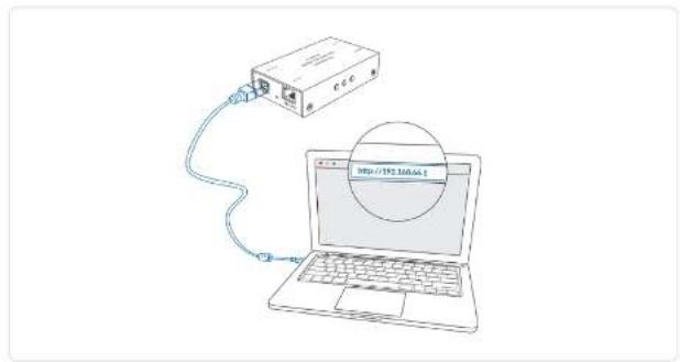
Solution 2: using Ethernet over USB
RNDIS (For Microsoft)/ECM (For Mac/Linux) provides a virtual Ethernet link to the computer's operating system.
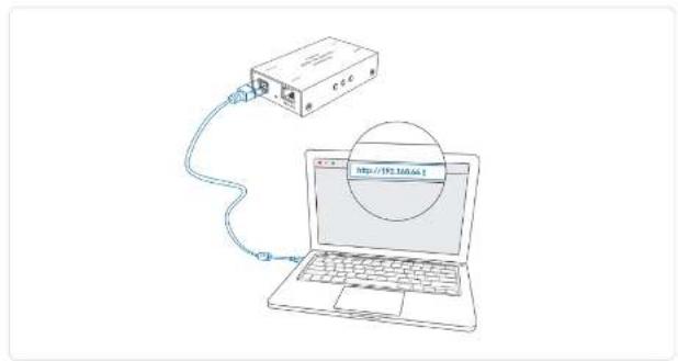
Step 1 Connect the device and your computer using a USB cable as shown on the left.
Step 2 Type the Ethernet over USB IP address in your web browser. The default address is 192.168.66.1.
The pop-up web UI of the connected device will be shown in your browser.
Please do not change it unless there is a conflict in your network.
⚠ Do not connect more than one Pro Convert device simultaneously to the same system via Ethernet over USB.
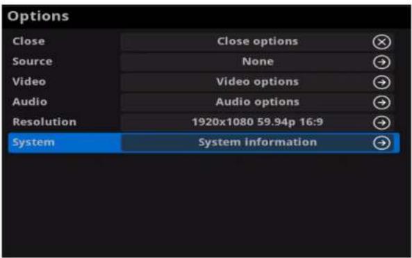
Figure 1 Select System In Options menu
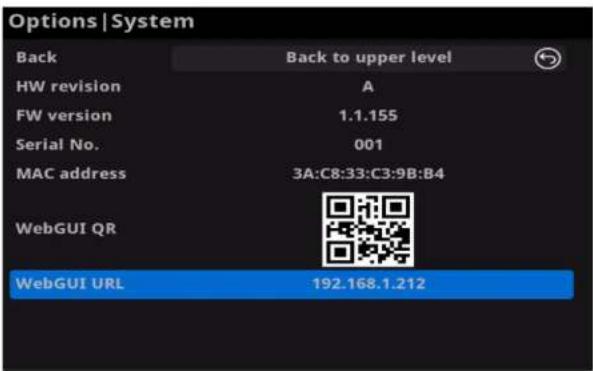
Figure 2 Check the WebGUI
Solution 3: using the on-screen menu Options
Step 1 Connect your decoder via Ethernet, power it up and connect a presentation device as shown in the Figure1. Connections.
Step 2 Press the on-device MENU button, click the mouse or the keyboard(if connected), to display the Options overlaid on the output.
Step 3 Go to the System option and check for the device WebGUI URL or scan the WebGUI QR to open the web UI in your web browser within the same LAN with your decoder.
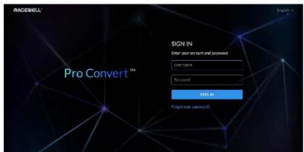
Signing In/Out
The Web UI allows multi-users to have read/write access to make configuration settings at the same time after logging-in. However, to avoid configuration conflicts, we do not recommend you to operate one device simultaneously.
- The default administrator account name and password are as follows:
Username: Admin
Password: Admin
- It is recommended to change the admin password after login (see modify the admin password). Unlike the password, the administrator username cannot be modified.
- Your account will sign out automatically if there is no operation performed within ten minutes.
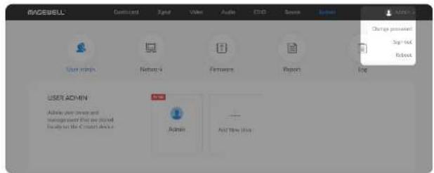
Step 2 Signing Out: click the drop-list icon behind your username at the top-right of the Web UI, and select Sign out.
Dashboard
The Dashboard tab in the web UI can show the real-time status and parameters of the Pro Convert device. Click and enter the Dashboard tab to check current device status.
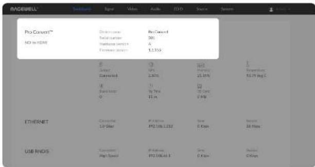
Checking Basic Information
• Device name shows the name of your Pro Convert unit.
Only the Administrator can modify the device name in the System > Network tab. For detailed information, refer to Setting Device Name.
- Serial number shows the serial number of your unit, which is also marked on your device.
• Hardware version shows the hardware version of your unit.
- Firmware version shows the current firmware version that's installed in your unit. Only the Administrator can update the firmware, via the System > Firmware tab. For detailed information, refer to Updating the Firmware.
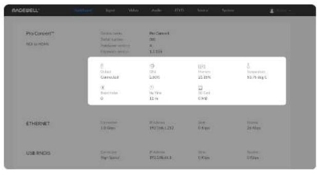
Checking the Current Working Status
- Output shows whether an output device is connected to the Pro Convert device. This parameter would be displayed for device which has an HDMI interface. For AIO unit, it is HDMI Output.
- CPU shows the current CPU usage (the load on the processor, shown as a percentage) of the Pro Convert device. CPU usage increases when the device is handling more complex video processing tasks (e.g. decoding at higher resolutions and frame rates).
- Memory shows current memory usage. You can find out the free memory in System > Report tab, subject to administrative rights.
- Temperature shows the current temperature of the unit's processor. Keeping the device free from dust and avoiding a high-temperature work environment may help to avoid overheating of the device. If the core temperature is approaching 100°C, please try to lower the temperature by ensuring a supply of cooler air.
- Board Index shows the rotary switch number. You can change the number on the rotary switch to set a different Board Index.
- Up Time shows the elapsed time since your device's last boot-up.
- SD Card shows the capacity of current inserted SD card. This function is not available now.
- Fan Speed shows the current speed of fan, which automatically changes according to temperature. NOTE: This parameter is ONLY available for 4K products.
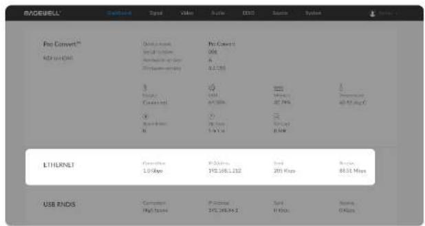
Checking Ethernet Status
• Connection shows Ethernet network connection status.
- IP Address shows Ethernet IP Address. You can manually change it in the System > Network tab with administrative rights.
- Send shows the current Ethernet transmission speed.
• Receive shows the current Ethernet receive speed.
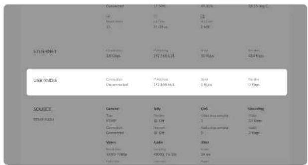
Checking Ethernet over USB Status
• Connection shows Ethernet over USB connection status.
- IP Address shows Ethernet over USB IP Address.
By default, it is 192.168.66.1. You can manually change it in the System > Network tab, with administrative rights.
- Send shows current Ethernet over USB send speed.
- Receive shows current Ethernet over USB receive speed.
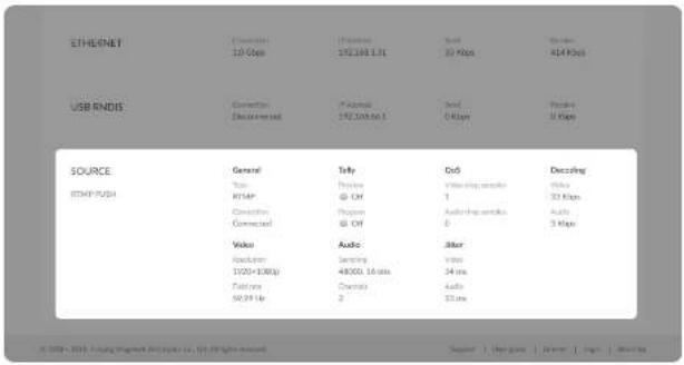 |
Checking Source Status
Settings of decoded video stream refers to the Source tab.
- General shows video source information.
- Type shows the decoding stream type which is specified in the Source tab.
• Connection shows whether a stream data is received by your decoder.
• Tally shows the decoded stream 'on-air' status.
NOTE: This group of parameters is ONLY available for NDI decoders.
- Preview shows whether the decoded source stream is being previewed. If yes, it shows On and is green, otherwise, it is Off and grey.
- Program shows whether the decoded source stream is being programmed. If yes, it shows On and is red, otherwise, it is Off and grey.
- QoS shows the number of frames dropped in the previous second.
• Video drop samples shows dropped video samples in the previous second.
• Audio drop samples shows dropped audio samples in the previous second.
• Decoding shows the decoding speed in the previous second.
• Video shows the video bitrate for the previous second.
• Audio shows the audio bitrate for the previous second.
• Video shows the decoded video information.
• Resolution shows the decoded video resolution.
• Field rate shows the decoded video field rate.
• Audio Shows audio information.
• Sampling shows the sampling rate and bit depth of the audio source.
• Channels shows the total number of source audio channels.
- Jitter Shows the time difference between the estimated and actual arrival time of a frame of source image.
• Video shows the video time difference.
• Audio shows the audio time difference.
Signal
Click and enter the Signal tab to check the signal information which is being decoded by the device.
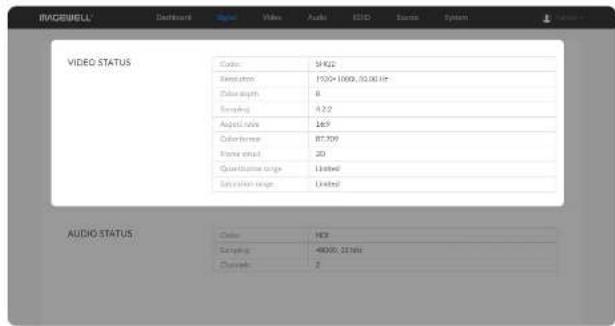
Checking VIDEO STATUS
- Codec shows the video encoding format.
• Resolution shows the chosen stream pixel resolution & frame rate.
• Color depth shows the chosen stream color depth, in bits.
• Sampling shows the chosen stream color sampling format. - Aspect ratio shows the chosen stream aspect ratio.
• Color format shows the chosen stream color encoding format.
• Frame struct shows the chosen stream frame type, it is always 2D.
• Quantization range shows the quantization range, e.g. Full or Limited.
• Saturation range shows the saturation range, e.g. Full or Limited.
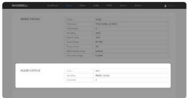
Checking AUDIO STATUS
• Codec shows the audio encoding format.
- Sampling shows the audio sampling rate and bit depth of the chosen stream.
• Channels shows the number of audio channels of the chosen stream.
Video
Click and enter Video tab to modify the video format according to your needs. By clicking Reset to Default in the bottom right corner of the page, you can cancel your modified settings.
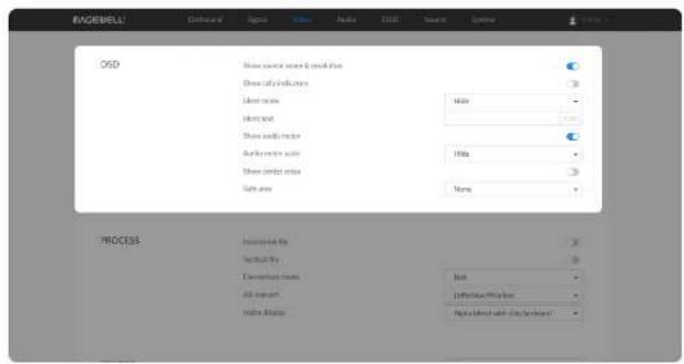
Setting OSD
Choose the overlay layers on the output gear.
• Show source name & resolution
Turn on the switch to show current decoded stream name at the top of the output display. By default, it is off.
• Show tally indicators
NOTE: This function is ONLY available for NDI decoders.
Turn on the switch to show the "on-air" status of selected stream at the top field of the output. If being previewed, it is PREVIEW/REVIEW/non-air, it is PROGRAM/PROGRAMators locate beside the source name & resolution; otherwise, there is nothing displayed. By default, it is off.
- Ident mode
Choose to show/hide the device name or ident text that overlays the output. It is used to separate multiple decoders from each other when they are working together. By default, it is Hide.
The device name can be modified in the System tab with administrative rights. The steps refer to Setting Device Name.
Ident text can be edited in the Ident text option.
- Ident text
Custom digital label overlaid on the output. By default, it is null. The text will be overlaid on the output when the Ident mode is set to Show ident text.
The label text ranges from 1 to 32 characters which contains A to Z, a to z, 0 to 9, and special characters including spaces, dash(), minus(-) and plus(+) sign.
• Show audio meter
Check the box to show the volume bar on the left side of presentation screen. By default, it is overlaid on the output.
- Audio meter scale
Choose the scale for the measurement of the volume.
- If CONVERT MODE in the Audio tab is EBU, options are Hide, Show dBu scale, Show post gain dBu scale, and Show post gain dBFS scale. If audio gain is set, the Show post gain dBu scale, and Show post gain dBFS scale will show the gain effect. By default, it is Hide.
- If CONVERT MODE in the Audio tab is SMPTE, options are Hide, Show dBVU scale, Show post gain dBVU scale, and Show post gain dBFS scale. If audio gain is set, the Show post gain dBVU scale, and Show post gain dBFS scale will show the gain effect. By default, it is Hide.
• Show center cross
Turn on the switch to overlay the center cross on the output screen which determines the center position of the entire image, helps with interlaced scans check and static convergence.
- Safe area
It ensures that the most important parts of the picture are seen by the majority presentation device. Choose from None. Show 80% center view area, Show 4:3 aspect ratio area, and Show square aspect ratio area. By
default, it is None.
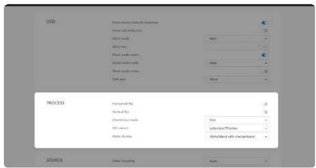
Setting PROCESS Format
By clicking Reset to Default in the bottom right corner of the page, you can cancel all settings.
- Horizontal flip
Turn on the switch to set a mirror effect of the video, making sure the viewer see the image in the right direction. By default, it is off.
- Vertical flip
Turn on the switch to reverse the active image vertically, making sure the viewer see the image in the right direction. By default, it is off.
- Deinterlace mode
Convert interlaced source video into a progressive one using Weave or Bob method.
- Weave takes pairs of fields and puts them together (every other line) to one frame. The result is the same as no deinterlacing. This mode is used when users want to capture the original video.
- Bob blends the top and bottom & field together. By default, this is used.
- AR convert
Set the method to convert the aspect ratio of the decoded video.
- Letterbox/Pillarbox indicates to adapt the display size of the presentation screen by filling with black borders to keep the aspect ratio of the source image. Letterbox features to fill in black bars at the top and bottom while pillarbox filling in left and right. By default, this is used.
• Full Screen indicates to stretch the video image to fill the presentation screen. - Zoom/Crop indicates to use the screen aspect ratio as the decoded video aspect ratio by stretch or compression.
- Alpha display
Note: This feature is ONLY supported by NDI to HDMI 4K decoder. Specify the effect of the alpha channel. By default, a gray checkerboard will be displayed in images where an alpha channel is present. Options are:
Original image
MAGEWELL®
• Alpha only:
MAGEWELL®
• Alpha blend with white:
MAGEWELL®
• Alpha blend with black:
• Alpha blend with checkerboard:
Setting SOURCE Format
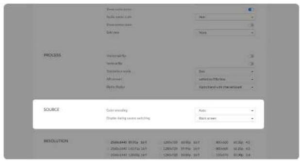
- Color encoding Set the color space to BT.601 or BT.709. When it is set to Auto, the color space will be BT.601 for SD and BT.709 for HD according to the source.
- Display during source switching Set the image to either Black screen or Keep last picture of the previous video when the source is changed.
Setting RESOLUTION
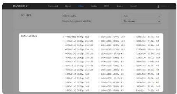
HDMI decoder lists all selections of resolution, frame rate and aspect ratio according to the capability of the connected presentation gear in the RESOLUTION section. Options varies according to the presentation devices. SDI decoder lists all supported output formats. NDI to SDI/AIO decoder supported formats are as follows.
1920x1080p60/59.94/50/30/29.97/25/24/23.98
1920x1080i60/59.94/50
• 1280x720p60/59.94/50/30/29.97/25/24/23.98
720x576i50
720x48059.94
For AIO decoder,
- If only SDI output is connected, RESOLUTION section shows all supported output formats.
- If only HDMI output is connected, RESOLUTION section shows the capability of the connected presentation gear.
- If HDMI and SDI output are connected simultaneously, RESOLUTION section shows the capability of the HDMI interface connected presentation gear. Choose the appropriate resolution in the above SDI list to ensure that both interfaces have smooth data flow.
Specify the resolution to meet your needs, or else the default mode is recommended.
Audio
Click and enter the Audio tab to set the output.
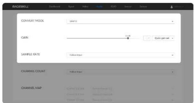
- CONVERT MODE
Two ways are provided for audio values conversion between source and output signal: EBU, SMPTE. By default, it is SMPTE.
GAIN
Adjust the gain from -100.00dB to 20.00dB as needed. Or you can select +20 dB, +10 dB, +0 dB, -20 dB, -40 dB or Mute (-inf dB) from the Quick gain set. By default, it is 0.
- SAMPLE RATE
Choose the proper sample rate for your work, including Follow input, 32000Hz, 44100Hz, 48000Hz, 88200Hz, 96000Hz. By default, it is Follow input.
⚠ For decoder with SDI output, sample rate can only be set to 48000Hz.
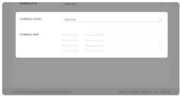
- CHANNEL COUNT
Choose the proper audio channels for your work, including Follow input, 2 Channels, 4 Channels, 8 Channels. Then you can set the mapping relationship between the output and source channels. By default, it is Follow input.
- CHANNEL MAP
Map the audio channels between the output and source channels when the CHANNEL COUNT is not Follow input.
- If the CHANNEL COUNT is set to 2 Channels, you can select audio channels mapping for Channel 1/2.
- If the CHANNEL COUNT is set to 4 Channels, you can select audio channels mapping for Channel 1/2 & 3/4.
- If the CHANNEL COUNT is set to 8 Channels, you can select audio channels mapping for Channel 1/2, 3/4, 5/6, 7/8.
EDID
EDID shows the EDID of the presentation device connected via HDMI output port. Decoders equipped with HDMI interface support this function.
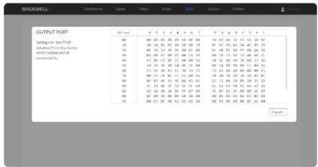
- Export: Click and set the file name to export the current EDID as a .bin file.
Source
Click and enter the Source tab to do the settings.
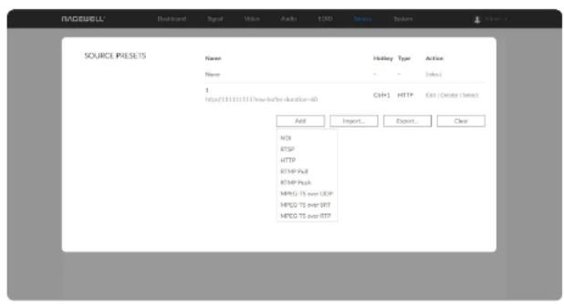
Setting SOURCE PRESETS
SOURCE PRESETS shows saved stream sources adding manually. For NDI® decoders, you can also choose the sources from the NDI® SOURCES. By default, it is None, which means not to decode.
- Click Edit to modify the parameters of the stream.
- Click Delete to remove the source from the list.
- Click Select to decode current source stream.
- Click Add to select streams of NDI (only supported by NDI @decoders), RTSP, HTTP (including HTTP and HLS, HTTP Live Streaming), RTMP Pull/Push and MPEG-TS over UDP/SRT/RTP to join to the list.
- Click Import... to choose the JSON file listing all converted data sources.
- Click Export... to save current preset list as a JSON file.
- Click Clear to delete all presets. Please be cautious that it will delete all listed presets.
Notes
- The source name of each stream in the presets list should be unique.
- Either name or URL is required when adding a new ND[ Source to an ND] decoder.
- NDI®sources that can not be auto-detected but can be pinged by the NDI® decoder, can be added to the preset list.
- When adding RTMP Push stream to the decoder, the port number specified by the sender should be 1935 or be omitted, and the stream key of the sender and receiver should be identical.
- If the source MPEG-TS over SRT stream has a password. Encrypted and Passphrase is required when being added to decoding list. The decoder can be either a caller or a listener.
- For NDI®source, the buffer duration ranges from 1 to 120 ms, while the non-NDI type of source ranges from 1 to 800 ms.
NDI
• To add an NDI source discovered by the decoder automatically
- The auto-detected NDI sources are listed in the NDI ^® SOURCES section below. Select the target stream and click Save as preset to add it to the preset list after specifying an Alias name for it.
• To add an NDI source manually
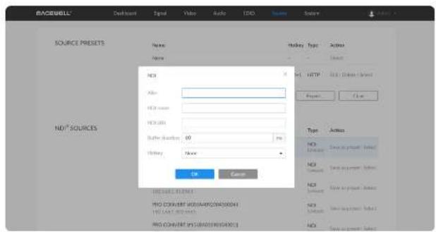
- Alias: Specify an alias name for current preset task for your convenience of the presets management, which will be displayed in the presets.
- NDI name: Enter the steam name of ndi source, which is case insensitive.
- NDI URL: Enter the steam address of ndi source formed like ip-address:port. For example, if you want to add a source named PRO CONVERT (#00 (A409200420003)) 192.168.1.1:5961 to the presets list, fill in the parameter with 192.168.1.1:5961.
- Either a name or a URL is required when adding a new NDI source. Ensure that the two properties are those of the same unit when you are
filling in them both.
- Buffer duration: Enter a number between 1 and 120, and the default value is 60. The buffer duration is suggested to be greater than the Jitter value shown in the Dashboard tab for a smoothy video. Shorten it when low latency matters, otherwise the default value is recommended.
- Hotkey: By default it is none. It allows you to switch decoding stream by pressing the specified Hotkey on the keyboard connected to the decoder. AIO decoder dose not have the function as the peripheral connected USB interface is replaced by SDI socket.
RTSP
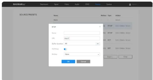
- Name: Specify a name for current preset task for your convenience of the presets management, which will be displayed in the presets.
- URL: Enter the RTSP URL. The URL syntax is rtsp://username:password@IP-address:port, username and password are from RTSP digest authentication.
- Buffer duration: Enter a number between 1 and 800, and the default value is 60. The buffer duration is suggested to be greater than the Jitter value shown in the Dashboard tab for a smoothy video. Shorten it when low latency matters, otherwise the default value is recommended.
- TCP First: By default it is on. As is, the decoder connects to the RTSP server over a TCP connection. When the switch is off or the TCP connection is timeout, a UDP connection is used instead. Set the switch by your network quality and layout.
• Hotkey: By default it is none. It allows you to switch decoding stream by
pressing the specified Hotkey on the keyboard connected to the decoder. AIO decoder dose not have the function as the peripheral connected USB interface is replaced by SDI socket.
HTTP
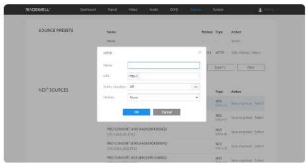
- Name: Specify an alias name for current preset task for your convenience of the presets management, which will be displayed in the presets.
- URL: Enter the URL of the decoded HTTP (or HLS) stream.
- Buffer duration: Enter a number between 1 and 800, and the default value is 60. The buffer duration is suggested to be greater than the Jitter value shown in the Dashboard tab for a smoothy video. Shorten it when low latency matters, otherwise the default value is recommended.
- Hotkey: By default it is none. It allows you to switch decoding stream by pressing the specified Hotkey on the keyboard connected to the decoder. AIO decoder dose not have the function as the peripheral connected USB interface is replaced by SDI socket.
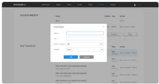
RTMP Pull
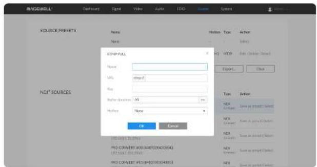
- Name: Specify an alias name for current preset task for your convenience of the presets management, which will be displayed in the presets.
- URL: Enter the RTMP URL address, or an RTMP address you obtained from the live stream platform.
• Key: Enter the stream key. - Buffer duration: Enter a number between 1 and 800, and the default value is 60. The buffer duration is suggested to be greater than the Jitter value shown in the Dashboard tab for a smoothy video. Shorten it when low latency matters, otherwise the default value is recommended.
- Hotkey: By default it is none. It allows you to switch decoding stream by pressing the specified Hotkey on the keyboard connected to the decoder. AIO decoder dose not have the function as the peripheral connected USB interface is replaced by SDI socket.
RTMP Push
As is to send RTMP streams to the decoder, the URL of the decoder is the destination.
- Name: Specify an alias name for current preset task for your convenience of the presets management, which will be displayed in the presets.
• Key: Enter the stream key. - Buffer duration: Enter a number between 1 and 800, and the default value is 60. The buffer duration is suggested to be greater than the Jitter value shown in the Dashboard tab for a smoothy video. Shorten it when low latency matters, otherwise the default value is recommended.
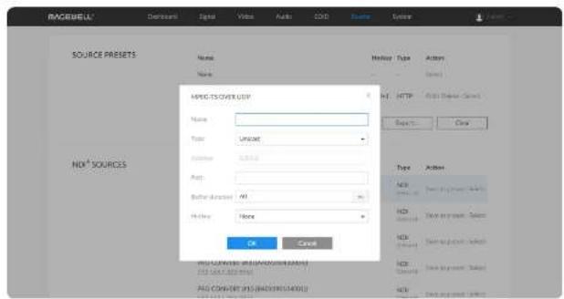
- The destination address of the sender must be consistent with the automatically generated address at the bottom of the pop-up configuration window.
- Hotkey: By default it is none. It allows you to switch decoding stream by pressing the specified Hotkey on the keyboard connected to the decoder. AIO decoder dose not have the function as the peripheral connected USB interface is replaced by SDI socket.
MPEG-TS over UDP
- Name: Specify an alias name for current preset task for your convenience of the presets management, which will be displayed in the presets.
- Type: Select the Unicast or Multicast. When unicast is selected, the data source streams to the decoder. When selecting multicast, you need to specify the multicast address to get the decoded stream.
- Address: Enter the address when the Type is Multicast.
- Port: Enter the port number specified by the streamer.
- Buffer duration: Enter a number between 1 and 800, and the default value is 60. The buffer duration is suggested to be greater than the Jitter value shown in the Dashboard tab for a smoothy video. Shorten it when low latency matters to your session, otherwise the default value is recommended.
- Hotkey: By default it is none. It allows you to switch decoding stream by pressing the specified Hotkey on the keyboard connected to the decoder. AIO decoder dose not have the function as the peripheral connected USB interface is replaced by SDI socket.
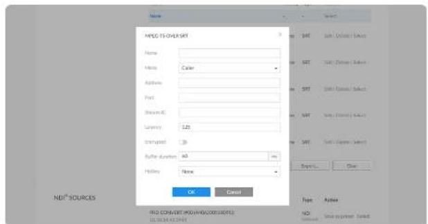
MPEG-TS over SRT
- Name: Specify an alias name for current preset task for your convenience of the presets management, which will be displayed in the presets.
- Mode: Select the Caller or Listener. The decoder can be worked as either a SRT Caller to call a listener, or a SRT Listener to be called.
- Address: Enter the Listener address when the Mode is set to Caller. If the SRT listener and caller are on the same LAN, enter the private IP address of the SRT listener on the LAN. If the SRT listener and caller are in different network environments, enter the public IP address of the SRT listener.
• Port: Enter the port number specified by the streamer. - Stream ID: Specify Stream ID for a SRT Caller. It should be consistent with the Stream ID of the sender, ranging from 0 to 512 characters. You can leave it empty if sender has no stream ID.
- Latency: Enter a number between 20 to 8000. The default value is 125. We recommend that the latency of the decoder is configured the same as that of the streamer.
- Encrypted: Turn on the switch when decoding an encrypted stream.
• Passphrase: Enter the password phrase for the encrypted stream. - Buffer duration: Enter a number between 1 and 800, and the default value is 60. The buffer duration is suggested to be greater than the Jitter value shown in the Dashboard tab for a smoothy video. Shorten it when low latency matters, otherwise the default value is recommended.
• Hotkey: By default it is none. It allows you to switch decoding stream by
pressing the specified Hotkey on the keyboard connected to the decoder. AIO decoder dose not have the function as the peripheral connected USB interface is replaced by SDI socket.
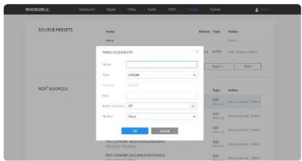
MPEG-TS over RTP
- Name: Specify an alias name for current preset task for your convenience of the presets management, which will be displayed in the presets.
- Type: Select the Unicast or Multicast. When unicast is selected, the data source streams to the decoder. When selecting multicast, you need to specify the multicast address to get the decoded stream.
- Address: Enter the address when the Type is Multicast.
- Port: Enter the service port specified by the streamer.
- Buffer duration: Enter a number between 1 and 800, and the default value is 60. The buffer duration is suggested to be greater than the Jitter value shown in the Dashboard tab for a smoothy video. Shorten it when low latency matters, otherwise the default value is recommended.
- Hotkey: By default it is none. It allows you to switch decoding stream by pressing the specified Hotkey on the keyboard connected to the decoder. AIO decoder does not have the function as the peripheral connected USB interface is replaced by SDI socket.
Setting NDI®SOURCES
NOTE: This section of parameters is ONLY available for NDI®decoders.
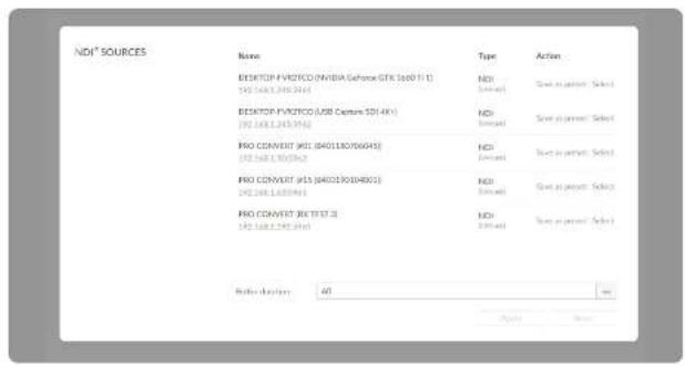
- NDI®sources auto-detected by the decoder are list here. The sources, which are in the specified group and be able to pinged, are included, if Discovery Server is enabled in the NDI®OPTIONS section.
- Click Save as preset to add current stream to SOURCE PRESETS list.
- Click Select to start decoding current stream.
- Buffer duration ranges from 1 to 120ms. We recommend that you set the value greater than the Jitter in the Dashboard tab.
- If low latency matters, you can shorten the Buffer duration. Otherwise, the default value 60 ms is recommended.
- Click Apply after modification.
- You can click Reset to reset the buffer to default value.
Setting NDI®OPTIONS
NOTE: This section of parameters is ONLY available for NDI®decoders.
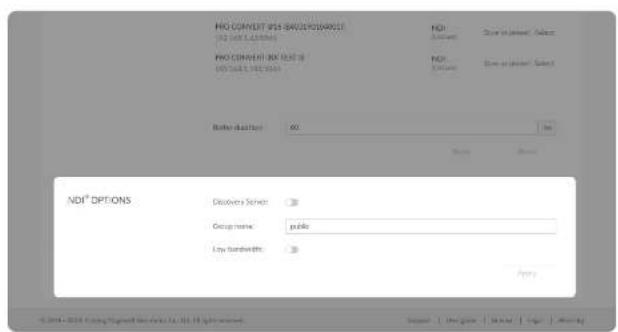
- Discovery Server
Turn on the switch for the decoder to auto-detect a source sender in different network segment but be able to pinged. And the Server IP should be the IP address of the server running discovery server software. By default, it is off.
Pro Convert family product can be used as a discovery server due to the build-in Discovery Service. This feature starts automatically when your device is power on, and requires zero configuration.
- Group name
Specify the Group name which the source belongs to. It is non case-sensitive, and should contain A to Z, a to z, 0 to 9 and special characters like _. The group name entry can contain comma-separated values, allowing your decoder to receive all the groups listed here.
By default, it is public.
- Low bandwidth
Turn on the switch for decoding NDI®stream when the network bandwidth is too low to have a smooth video. Generally, if the resolution is higher than 2048 x 1080, the height and width will be reduced to a quarter of the original, that is one-sixteenth of the original resolution; otherwise the height and width will be reduced to half of the original value, that is one-quarter of the original resolution. Meanwhile, the frame rate will drop to about 15 FPS. By default, it is off.
Note that you need to click Apply at the bottom-right corner of the NDI®
OPTIONS to save changes.
System
With administrative rights, you can access the System tab to control more functions, such as:
- Creating or removing general user accounts for accessing the decoder
- Changing passwords for all users of the decoder
- Changing the decoder's name
• Network settings for joining a specific LAN - Updating firmware for the latest features and improvements
- Exporting reports and logs to get technical support
- Rebooting or resetting the decoder to fix problems
Otherwise, the System tab is invisible when you log in as a general user.
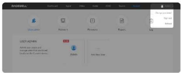
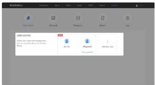
Creating/Removing General Users
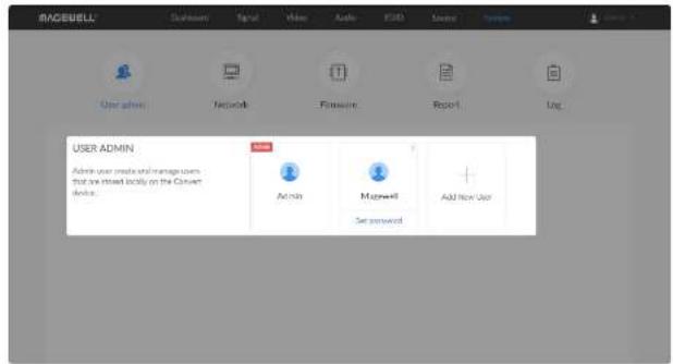
After signing in with default admin account, you may need to add general users to give them permissions to do basic operations, like monitoring the device, or setting some of the parameters.
Access the Web UI, and sign in as administrator.Step 1
Click and enter the System > User admin tab.Step 2
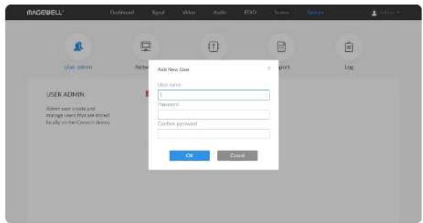
Click Add New User.Step 3
Type in the user name, password, and confirm your password.Step 4
- The username is a string of 3 to 12 characters, which contains the letters A-Z, a-z, numbers 0-9 and underscore.
- The password is a string of 1 to 32 characters, which contains the letters A-Z, a-z, numbers 0-9 and special characters _\~!@#\$%^&*-1=.
Click OK.Step 5
Repeat Step 3 to 5 to add multiple users.Step 6
Decoders support the addition of up to 15 general users.
Step 7 To delete a user, move the cursor to the user name you want to delete, then click the delete button X appeared at the top-right corner.
Confirm the deletion when prompted. Step 8
Setting Password
After login, You can either set up a password in the user account drop-list, or in the System tab (with administrative rights).
Solution 1: Setting via the user account drop-list
Access the Web UI, and sign in with your username and password. Ste
Step 2 Click the drop-list icon beside the logged-in username, and click Change password.
Step 3 In the prompt window, type in your old password, the new password, and confirm your new password.
The password is a string of 1 to 32 characters, which contains letters A-7, a-z, numbers 0-9 and special characters _\~!@#\$%^&*+=. Click OK.Step 4
Solution 2: Setting in the System tab
Step 1 Access the Web UI and sign in from the administrator account, then you can change any user's password. Click and enter the System tab.Step 2
Step 3 Move the cursor to the specific user name, then click Set password. In the prompt window, type in and confirm your password.Step 4 The password is a string of 1 to 32 characters, which contains letters A-Z, a-z, numbers 0-9 and special characters _\~!@#\$%^&*-=, Click OK.Step 5
Setting Device Name
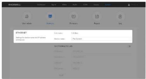
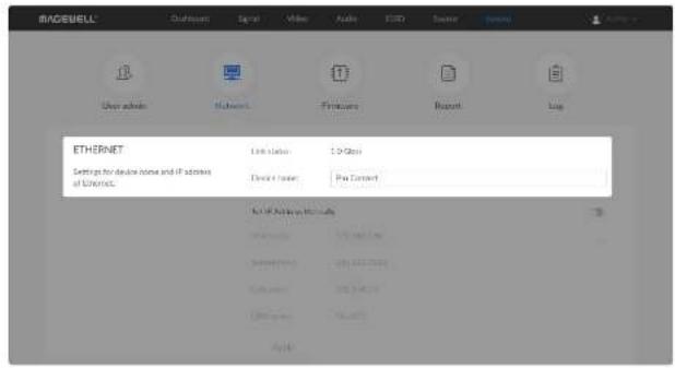
To change device name in the System tab requires administrative rights. By default, the device name is the same as the product model name.
Access the Web UI, and sign in as administrator.Step 1
Step 2 Click and enter the System tab, then select Network.
Enter a new Device name Step 3
The device name is a string of 1 to 30 non-case sensitive characters, containing letters a to z, A to Z, 0-9, spaces and special characters like _-1.
Step 4 Click Apply to save changes, and confirm with Yes when prompted.
Network Settings
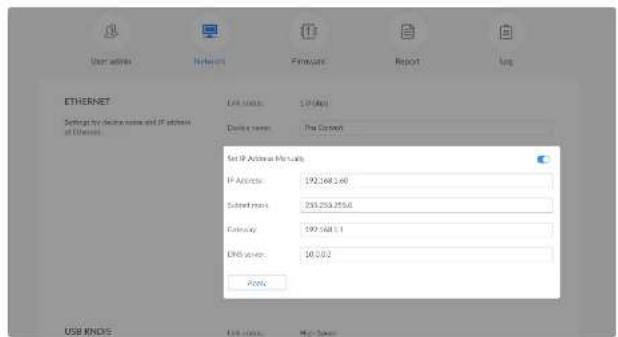
To change network connections in the System tab requires administrative rights. You can change the device name while setting network parameters. By default, the Pro Convert unit automatically detects any connected network. You can set a static IP Address if the device failed to auto-configure using DHCP. If multiple devices are connected using Ethernet over USB, change the RNDIS IP address according to your own arrangement.
Setting Ethernet IP Address
Access the Web UI, and sign in as administrator.Step 1
Step 2 Click and enter the System tab, then select Network.
Step 3 Turn on Set IP Address Manually, then enter a new IP address, Subnet mask, Gateway, and DNS server.
Click Apply to save changes.Step 4
When the prompt appears, click Yes.Step 5
Step 6 Type the manually assigned IP address in your web browser to access the Web UI, verifying if the network settings work.
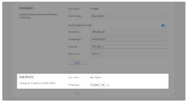
Setting Ethernet over USB IP Address
RNDIS (Microsoft's widely used Ethernet over USB protocol)/ECM (Ethernet Control Model) provides a virtual Ethernet link for the decoder to connect to a computer operating system.
Note:
- It is not recommended that you modify this IP address unless there is a conflict on your LAN.
- Do not connect more than one decoder simultaneously to one system when using Ethernet over USB.
Access the Web UI and sign in as administrator.Step 1
Step 2 Click and enter the System tab, then select Network.
Enter a new IP address for Ethernet over USB.Step 3
Step 4 Click Apply to save changes, then click Yes when prompted.
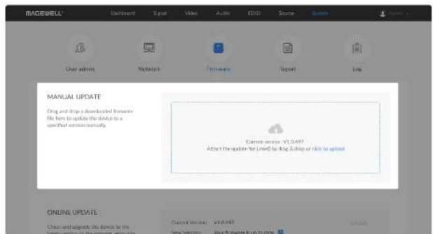
Figure1. Click to update
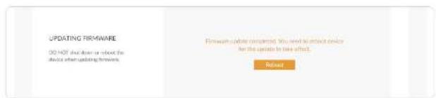
Figure2. Click Reboot
Updating the Firmware
To update the firmware via the System tab requires administrative rights.
Note: Currently online update is not supported.
Access the Web UI, and sign in as administrator.Step 1
Step 2 Click and enter the System tab, then select Firmware
Step 3 Click on click to update to select the .mwf firmware update file from your local storage, or just drag and drop the file from your computer into the upload zone.
You can download the Pro Convert firmware package from the Downloads section of the Magewell website: www.magewell.com/downloads/pro-convert.
Click Open to upload the updates package.Step 4
The device will automatically verify the update file. The unit will upload the file after the file verification is passed.
Step 5 In the Manual Update window, click Update.
DO NOT shut down or reboot the device when updating firmware. Click Reboot to complete the update.Step 6
The changes take effect after you reboot the device.
Step 7 Log in to your unit's Web UI and check the current Firmware version in the Dashboard tab.
The Firmware version should have changed to show the number of the new update.
Exporting Reports and Logs
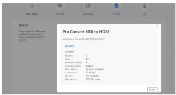
You can export reports and logs from your decoder when you want to get help from the Magewell Support team. These files will help our support engineers get a better understanding of your device status and other related equipment like the source device. These operations require administrative rights.
Exporting Reports
Access the Web UI and sign in as administrator.Step 1
Step 2 Click and enter the System tab, then select Report.
Click Export... to generate a .html file.Step 3
When the prompt appears, click Export.Step 4
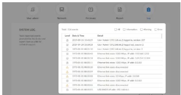
Clearing/Exporting All Logs
Access the Web UI and sign in as administrator.Step 1
Step 2 Click and enter the System tab, then select Log.
(Optional) Filter current logs.Step 3
By default, all logs are displayed in the table. Log entries can be categorized as "error", "warning", and "information".
• Total shows the total number of filtered events.
- All: Check to show all logs.
The device can store up to 1000 local log entries. After 1000 entries have been recorded, the oldest entry will be deleted before a new one can be added.
• Information: Check to show information logs - which record user actions or significant system events, e.g. login and signal locked.
- Warning: Check to show warning logs - which mean something has not worked as it should. e.g. Ethernet is disconnected or signal is unlocked.
- Error: Check to show error logs - which mean some serious error has happened.
Step 4 (Optional) Click Export... to get a .html file of all logs.
When prompted in the window, click Export.
(Optional) Click Clear to delete all logs.Step 5
When prompted in the window, click Yes.
Rebooting/Resetting Pro Convert
Rebooting/resetting your Pro Convert when problems are encountered.
Rebooting Pro Convert
⚠ Rebooting your device will not lose any of your configuration settings.
Access the Web UI and sign in as administrator.Step 1
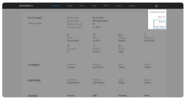
Step 2 Click the drop-list icon behind your username at the top-right of the Web UI and select Reboot or Auto reboot.
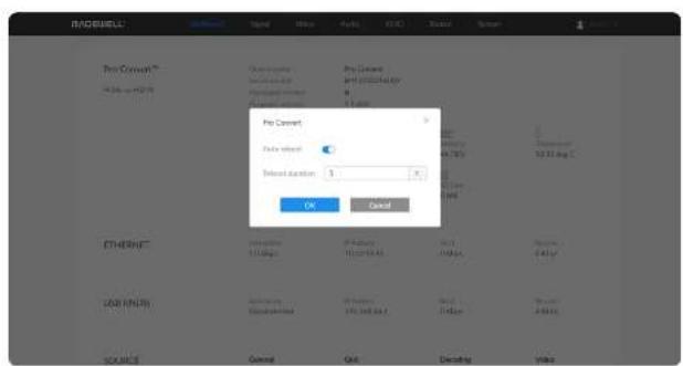
Step 3 When prompted in the window, click Reboot to restart decoder immediately; or turn on Auto reboot to schedule device restart and set Reboot duration between 1 to 576h.
For example, if Reboot duration is set to 24, it means your decoder will automatically restart every 24 hours.
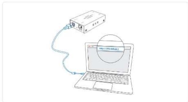
Figure1 Connections
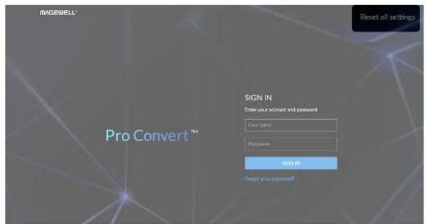
Figure2. Reset all settings
Resetting All Settings
⚠ Warning: Resetting your device will lose all your configuration data.
Connect the device and your computer with the USB cable.Step 1
Step 2 Launch your web browser and type in the Ethernet over USB address to access the Web UI SIGN IN page.
The default address is 192.168.66.1. Please do not change it unless there is a conflict in your network.
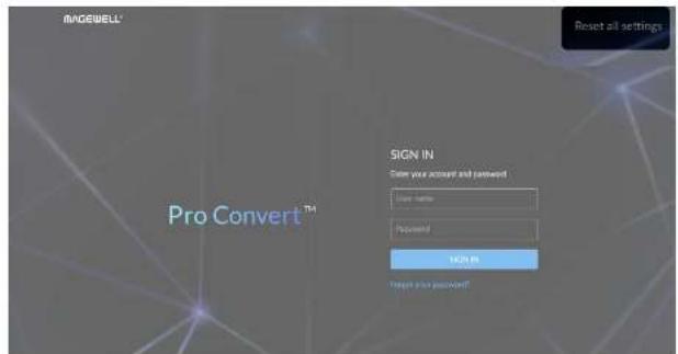
Step 3 Click Reset all settings at the top right corner of the SIGN IN page. The reset process may take a few minutes.
OSD Menu Configuration
Pro Convert provides quick settings for your device via a on-screen Options menu, allowing you to quickly set up new sessions. In the following sections, we take Pro Convert for NDI® to HDMI 4K as an example to describe the functions which can be configured by the OSD Options menu. Configurations and operations of other decoders are alike.
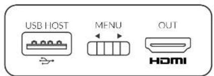
Figure 1 MENU button on 4K device
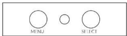
Figure 2 MENU&SELECT buttons on 2× device
Table 1. Functions of the on-board button(s)
| Product name Button Functions | ||
| for NDI®to HDMI 4KH.26x to HDMI 4K | MENU Press to display the menu or select current parameter, or toggle the switch left and right to cycle through the options. | |
| for NDI®to SDIfor NDI®to HDMIfor NDI®to AIOH.26x to SDIH.26x to HDMI | MENU Press to display the menu, orcycle through the options. | |
| for NDI®to SDIfor NDI®to HDMIfor NDI®to AIOH.26x to SDIH.26x to HDMI | SELECT Press to display the menu, enter current option, or confirm the selection of specific function. | |
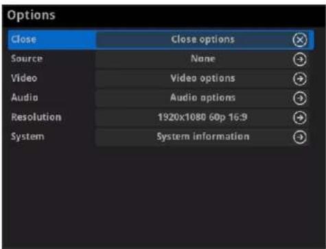
Accessing the Options Menu
Follow the operations below to turn on/off the Options menu.
- Press the MENU or SELECT (only on 2K device) button on the device to activate the Options menu.
- Click the mouse or space/enter key of the key board connected to the decoder to activate the Options menu.
- Select the Close > Close options to exit from the Options menu.
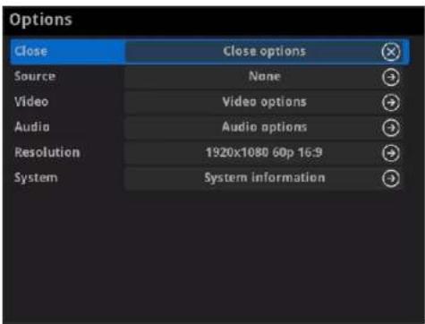
Options
- Close
Choose to exit from the Options menu.
- Source
Choose the specific video source to decode. Press hotkey to quickly switch the decoding source. To check hotkey of presets refer to SOURCE PRESETS in the Web UI.
you can use Web UI to add source manually. For detailed information, refer to Web UI > Source tab.
- Video
Choose to specify video parameters for your session. For detailed information, refer to Options > Video.
- Audio
Choose to specify audio parameters for your session. For detailed information, refer to Options > Audio.
PTZ
Choose to specify PTZ parameters for source connected IP camera. For detailed information, refer to Options > PTZ.
- Resolution
Choose to specify resolution for presentation.
The decoder will list supported selections of resolution, frame rate and aspect ratio in the RESOLUTION section. Options varies according to the presentation appliances.
Specify the resolution to meet your needs, or else the default value is recommended. For detailed information, refer to Options > Resolution.
- System
Choose to check the device information, including IP address etc., For detailed information, refer to Options > System.
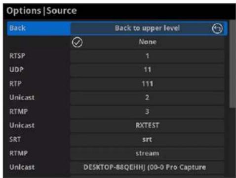
Source
- Back
Choose to go back to Options interface.
- Select streams of RTSP, Unicast (only supported by NDI®decoders), Multicast (only supported by NDI®decoders), RTMP (Pull/Push), UDP, RTP, HTTP (including HTTP and HLS, HTTP Live Streaming) or SRT stream to decode.
You can use Web UI to add source manually. For detailed information, refer to Web UI > Source.
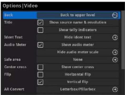
Video
- Back
Choose to go back to Options interface.
• Title
Set the overlay layers on the output appliance.
• Show source name & resolution
Check the box to show current decoded stream name at the top of the output display. By default, it is off.
• Show tally indicators
NOTE: This function is ONLY available for NDI decoders. Check the box to show the "on-air" status of selected stream at the top field of the output. If being previewed, it is PREVIEW PREVIEW is PROGRAM PROGRAMators locate beside the source name & resolution; otherwise, there is nothing displayed. By default, it is off.
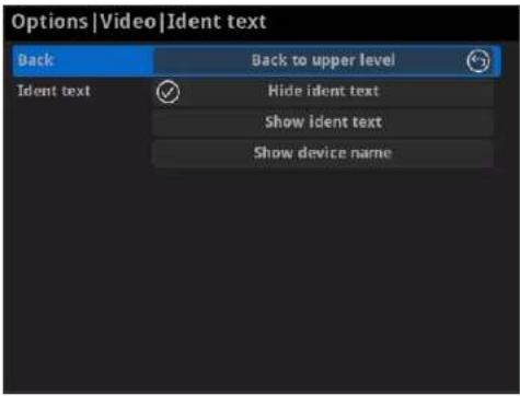
- Ident text
Choose to show/hide the ident text that overlays the output. It is used to separate multiple decoders from each other when they are working together. By default, it is Hide.
The device name can be modified in the Web UI > System tab with administrative rights. The steps refer to setting device name. The steps to editing ident text refer to setting ident text.
- Audio Meter
• Show audio meter
Check the box to show the volume bar on the presentation screen. By default, it is overlaid on the output.
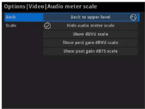
- Audio meter scale
Choose/hide the scale for the measurement of the volume.
If MODE in the Audio tab is EBU, options are Hide audio meter scale, Show dBu scale. Show post gain dBu scale, and Show post gain dBFS scale. If audio gain is set, the Show post gain dBu scale, and Show post gain dBFS scale will show the gain effect. By default, it is Hide audio meter scale.
If MODE in the Audio tab is SMPTE, options are Hide audio meter scale. Show dBVU scale. Show post gain dBVU scale, and Show post gain dBFS scale. If audio gain is set, the Show post gain dBVU scale,
and Show post gain dBFS scale will show the gain effect. By default, it is Hide audio meter scale.
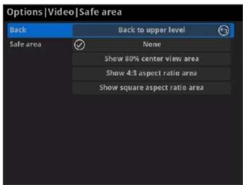
- Safe area
It ensures that the most important parts of the picture are seen by the majority presentation device. Choose from None, Show 80% center view area, Show 4:3 aspect ratio area, and Show square aspect ratio area. By default, it is None.
- Center cross
Choose Show center cross to overlay the center cross on the output screen which determines the center position of the entire image, helps with interlaced scans check and static convergence.
- Flip
- Horizontal flip Check the box to set a mirror effect of the video, making sure the viewer see the image in the right direction. By default, it is off:
- Vertical flip Check the box to reverse the active image vertically, making sure the viewer see the image in the right direction. By default, it is off.
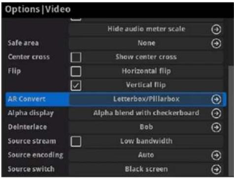
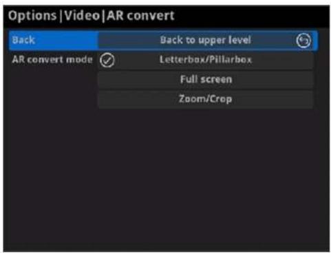
- AR Convert
- Letterbox/Pillarbox indicates to adapt the display size of the presentation screen by filling with black borders to keep the aspect ratio of the source image. Letterbox features to fill in black bars at the top and bottom while pillarbox filling in left and right. By default, this is used.
• Full Screen indicates to stretch the video image to fill the presentation screen. - Zoom/Crop indicates to use the screen aspect ratio as the decoded video aspect ratio by stretch or compression.
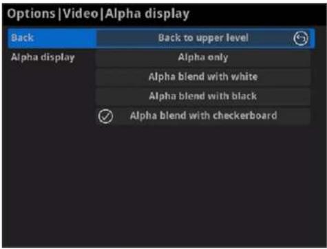
- Alpha display
Note: This feature is ONLY supported by the NDI to HDMI 4K decoder. Set the background displayed in images where an alpha channel is present. Options are Alpha only, Alpha blend with white, Alpha blend with black and Alpha blend with checkerboard.
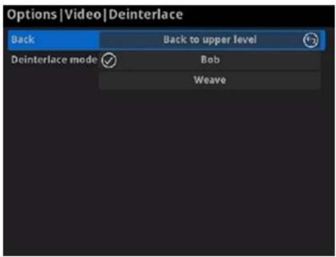
- Deinterlace
Convert an interlaced source video into a progressive one using Weave or Bob method.
• Weave takes pairs of fields and puts them together (every other line) to one frame. The result is the same as no deinterlacing. This mode is used when users want to capture the original video.
- Bob blends the top and bottom & field together. By default, this is used.
- Source stream
Check the box to decode streams when the network bandwidth is too low to have a smooth video. Generally, if the resolution is higher than 2018 x 1080, the height and width will be reduced to a quarter of the original, that is one-sixteenth of the original resolution; otherwise the height and width will be reduced to half of the original value, that is one-quarter of the original resolution. Meanwhile, the frame rate will drop to about 15 FPS. By default, it is off.
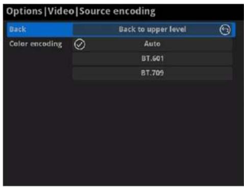
- Source encoding
Set the color space to BT.601 or BT.709. When it is set to Auto, the color space will be BT.601 for SD and BT.709 for HD according to the source.
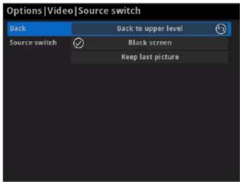
- Source switch
Set the image to either Black screen or Keep last picture of the previous video when the source is changed.
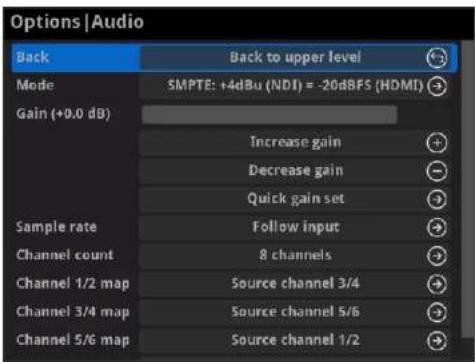
Audio
- Back Choose to go back to Options interface.
- Mode Two ways are provided for audio values conversion between source and output signal: EBU, SMPTE. By default, it is SMPTE.
- Gain Adjust the gain from -100.00dB to 20.00dB as needed. Or you can select +20 dB, +10 dB, +0 dB, -20 dB, -40 dB or Mute (-inf dB) from the Quick gain set. By default, it is 0.
- Sample rate Choose the proper sample rate for your work, including Follow input, 32000Hz, 44100Hz, 48000Hz, 88200Hz, 96000Hz. By default, it is Follow input.
- Channel count Choose the proper audio channels for your work, including Follow input, 2 Channels, 4 Channels, 8 Channels. Then you can set the mapping relationship between the output and source channels. By default, it is Follow input.
- When the CHANNEL COUNT is set to 2 Channels, select audio channels mapping for Channel 1/2. When the CHANNEL COUNT is set to 4 Channels, select audio channels mapping for Channel 1/2 & 3/4. When the CHANNEL COUNT is set to 8 Channels, select audio channels mapping for Channel 1/2, 3/4, 5/6, 7/8.
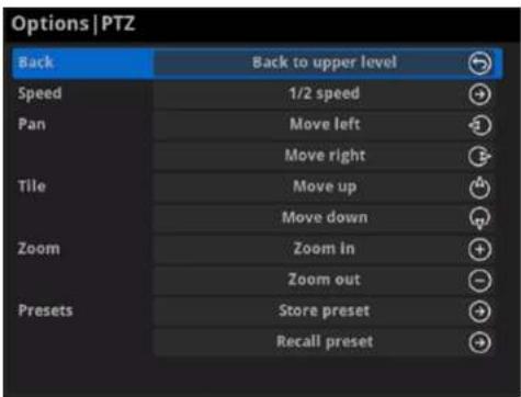
PTZ
Note: This function is ONLY supported by the NDI®decoder. The PTZ control function should be supported by the decoded source which connecting the PTZ camera.
- Back
Choose to go back to Options interface.
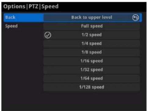
- Speed
Choose the camera moving speed from options including Full speed, 1/2 speed, 1/4 speed, 1/8 speed, 1/16 speed, 1/32 speed, 1/64 speed, 1/128 speed.
- Pan
Choose to move the camera left or right until your desired position.
- Tile
Choose to move the camera up or down until your desired position.
- Zoom
Choose to zoom in/out the camera to see your desired view.
- Preset
A preset is a predefined image position which contains information of pan, till, etc. After the preset is configured, you can call the preset. The camera will move to the programmed image position. Note: The function should be supported by the PTZ camera.
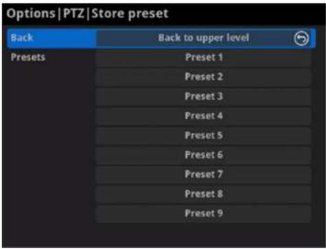
- Store preset
After moving the camera to your desired position, tap Store preset and choose the number up or down in the panel to save current position configurations. 9 presets can be saved.
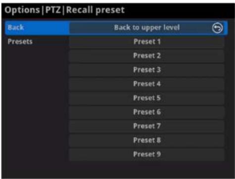
- Recall preset
If there are presets stored in camera, you can choose your desired preset number to quickly set up your camera.
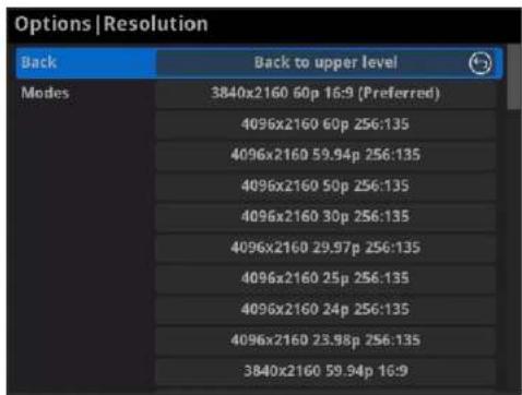
Resolution
The decoder will list all supported selections of resolution, frame rate and aspect ratio in the RESOLUTION section. Options varies according to the presentation appliances.
Specify the resolution to meet your needs, or else the default mode is recommended.
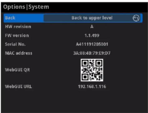
System
- Back Choose to go back to Options interface.
- HW revision Shows hardware revision of your device.
- FW version Shows firmware version of your device.
- Serial No.
Shows the serial number of your unit, which is also marked on your device.
• MAC address Shows the MAC address of your device. - WebGUI QR Scan the QR code to go to the Web UI.
- WebGUI URL Shows Ethernet IP Address. Type the URL into your web browser to display the Web UI. Then you can control the converter remotely.
FAQ
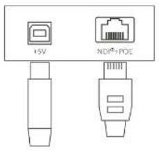
How to supply power to the Pro Convert
Power your decoder as shown in the left figure in 2 ways.
- Via USB: Plug in the supplied 5V power adapter via the USB cable to supply power.
- Via PoE: Plug in an Ethernet cable connected to a PoE switch or a PoE adapter for power and Ethernet connection.
Note:
• Pro Convert devices require a 5V DC source with a current rating of no less than 2.1A.
• We recommend that you use only the included Magewell accessories.
- If any included accessory is lost or broken, please contact your Magewell authorized local resellers for help.
Which version of NDI ^® SDK is compatible with Pro Convert?
Pro Convert is compatible with NewTek NDI®SDK 4.1 and above.
How long it takes for one frame to be received until it is displayed?
After testing, in a Gigabit Ethernet network, if using Philips 328M monitor as the presentation device, the minimum delay of converting 1080P60 signal is about 50 ms when the buffer duration is 20 ms.
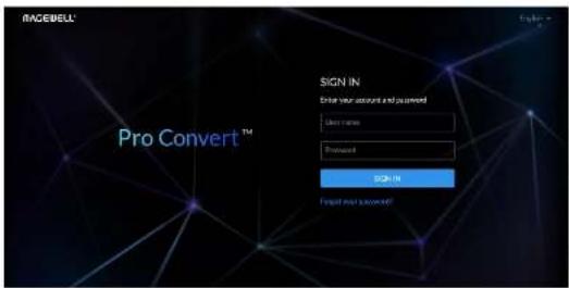
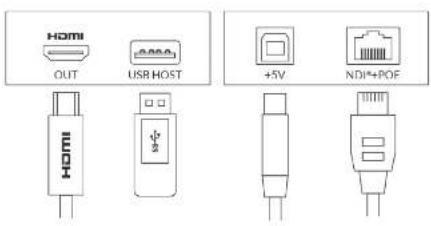
Figure1 Connections
How to configure Pro Convert via Web UI
Pro Convert allows you to set up and control via a web-based user interface as either an administrator or a general user.
You can get access to the Web UI using Windows File Explorer, through your web browser over a USB connection, or with menu Options.
Make sure that at least one of the following web browsers is installed in your system.
• Google Chrome version 49 and above
• Microsoft Internet Explorer 11
- Microsoft Edge
• Mozilla Firefox version 61 and above
• Apple Safari 11.1 and above
• Opera 55.0.2994.44 and above
1. Using Windows File Explorer
This method is available for Windows7/8/8.1/10 users.
Step 1 Connect your decoder via Ethernet and power it up. Connect a presentation device.
Open a File Explorer window in one of the following ways.Step 2
- Click on the Start Button and find File Explorer in the Start menu.
- Press the Windows logo key E.
- Select the folder icon on the taskbar.
Step 3 Select the Network view at the bottom of the list of items on the left
side of the File Explorer.
Turn on the network discovery function if prompted. Step 4
Step 5 Find your Pro Convert device in the Other Devices section, where it will be shown as "Pro Convert + #board index + (serial number)".
- The serial number (marked on your device) will be in a form like 'B410180706006'.
- The board index (the rotary switch number on your device) is shown like "04" or "#04".
Step 6 Double click the decoder icon to open the Web UI of the device in your web browser.
2. Using Ethernet over USB
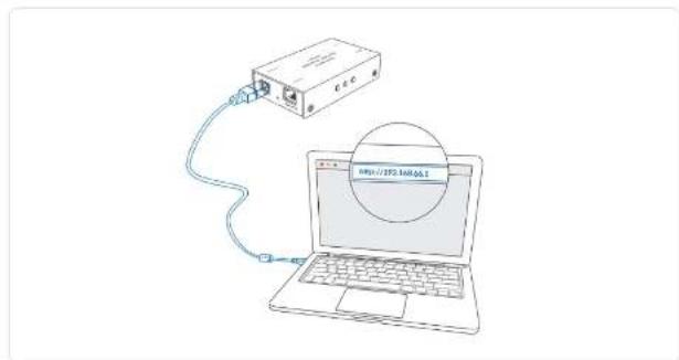
Step 1 Connect the Pro Convert device to your computer using the USB cable.
Step 2 Launch your web browser, and type in USB RNDIS address to access the Web UI. The default address is 192.168.66.1.
Step 3 Enter your account and password in the SIGN IN page, and configure the device after you login successfully.
The default admin account (case-sensitive) is Admin, Admin. It is recommended to change the admin password after log-in.
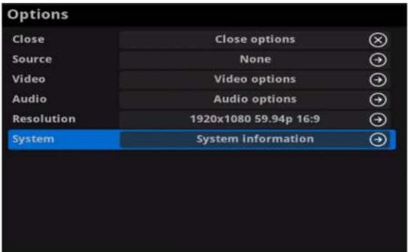
Figure1. Select System in Options menu
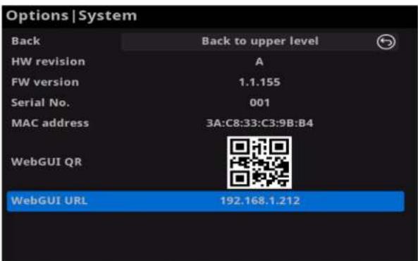
Figure2. Check the WebGUI
Solution 3: using the on-screen menu Options
Step 1 Connect your decoder via Ethernet, power it up and connect a presentation device as shown in the Figure1. Connections.
Step 2 Press the on-device MENU button, click the mouse or the keyboard(if connected), to display the Options overlaid on the output.
Step 3 Go to the System option and check for the device WebGUI URL or scan the WebGUI QR to open the web UI in your web browser within the same LAN with your decoder.
How to change device name
Pro Convert allows you to set up and control via a web-based user interface as either an administrator or a general user. Changing the device name requires administrator rights.
Access the Web UI, and sign in as administrator.Step 1
Click and enter the System > Network tab.Step 2
Change the Device name Step 3
The device name is a string of 1 to 30 non-case sensitive characters, containing letters a to z, A to Z, 0-9, spaces and special characters like _++.
Step 4 Click Apply to save your changes, and then click Yes when prompted.
It may take a few minutes for your settings to take effect.
Step 5 Click and enter the Dashboard tab in the Web UI to check the Device name. The values should be the same as your settings.
How to reset a Pro Convert device
⚠ Warning: Resetting your device will lose all your configuration data.
Connect your decoder to your computer.Step 1
Step 2 Launch your web browser, and type in the USB RNDIS address to access the Web UI SIGN IN page.
The default address is 192.168.66.1. Please do not change it unless there is a conflict on your network.
Step 3 Click Reset all settings at the top right corner of the SIGN IN page. The reset process may take a few minutes.
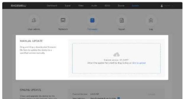
Figure1. Click to update
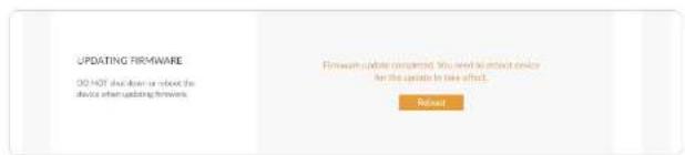
Figure2. Click Reboot
How to manually update the firmware for Pro Convert
You can update firmware via the Web UI with administrative rights.
Access the Web UI and sign in as administrator.Step 1
Step 2 Click and enter the System tab, then select Firmware.
Click on click to update.Step 3
Select the .mwf firmware update file from your local storage Step 4
You can download the Pro Convert firmware package from the
Downloads section of the Magewell website:
www.magewell.com/downloads/pro-convert.
Click Open to upload the updates package.Step 5
The device will automatically verify the update file.
The unit will upload the file after the file verification is passed.
Step 6 In the Manual Update window, click Update.
The device will verify the update file and automatically upload it if the verification is successful.
After loading successfully, click Reboot to complete the update.Step 7
The reboot process may take a few minutes.
Step 8 Login to the Web UI again and check the current Firmware version number in the Dashboard tab.
The Firmware version should now show the number of the new update.
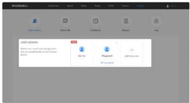
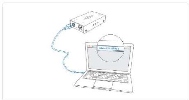
Figure 1. Connections
What to do if you forgot the password
If you are a general user, ask your administrator to set a new password for you. If you are the administrator, you need to reset all settings back to default values, then set a new admin password.
1. To reset a general user's password.
Access the Web UI, and sign in as administrator.Step 1 Click and enter the System tab.Step 2
Step 3 Click the Set password link which appears when your mouse hovers over the user name.
Step 4 Type in new password and confirm the new password as prompted in the window.
The password is a string of 1 to 32 case-sensitive characters, which contains A-Z, a-z, 0-9 and special characters _\~!@#\$%^&*-+=. Click OK.Step 5
2. To set a new admin password.
Connect the device to a computer with the USB cable.Step 1
Type in the USB RNDIS address to your web browser.Step 2
The default IP address of USB RNDIS is 192.168.66.1. Please do not modify it unless there is a conflict on your network.
Step 3 Click Reset all settings at the top-right corner of the SIGN IN page. The reset process may take a few minutes, and all configuration data will be lost - not just the passwords.
Step 4 Sign in to the Web UI via the default admin account (case sensitive): Admin, Admin.
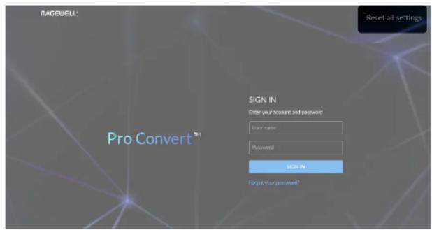
Figure2. Reset all settings
Click and enter the System tab.Step 5
Step 6 Click the Set password link which appears when your mouse hovers over the user name.
Step 7 Type in new password, and confirm the new password as prompted in the window.
The password is a string of 1 to 32 case-sensitive characters, which contains letters A-Z, a-z, numbers 0-9 and special characters _ - !@#\$%^&*-=.
Click OK.Step 8
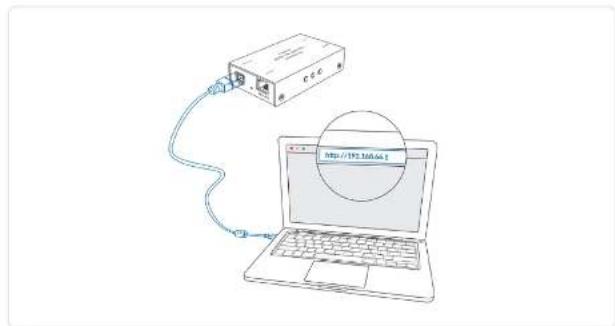
Figure1 Connections
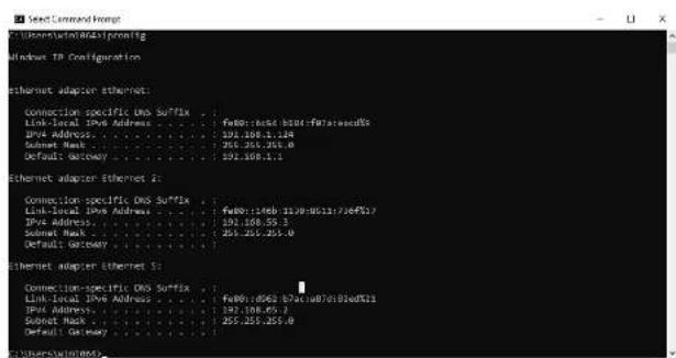
Figure2. Windows Command Line Interpreter
How to retrieve your USB RNDIS IP Address
Step 1 Connect the device and your computer with a USB cable as shown in Figure1. Connections.
Take the following steps according to your operating system.Step 2
- For Windows users
-
Type cmd in the search bar to start the command interpreter.
-
Type in ipconfig, and find an IPv4 address of the form 192.168.xxx.2, as shown in Figure2. Windows Command Line Interpreter.
- For Linux users
-
Launch the terminal.
-
Type in ifconfig -a, and find an IPv4 address of the form 192.168.xxx.2, as shown in Figure3. Linux Terminal.
• For Mac users
-
Click the System Preferences icon in the Dock or choose Apple menu > System Preferences.
-
Choose Network > Pro Convert, and check the IP Address, as shown in Figure4. Mac Network.
If 192.168.xxx.2 is taken, the IP address would automatically change to another value within the ranges of 192.168.xxx.2 to 192.168.xxx.254.
Type in 192.168.xxx.1 in your web browser to access the Web UI.Step
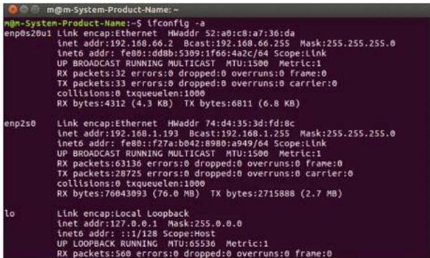
Figure3. Linux Terminal
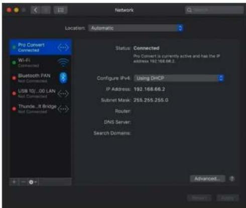
Figure4 Mac Network
Support
Get the Latest Information
If you have any problems using Magewell products or need more technical information, please visit the following channels.
- Tutorial video: www.magewell.com/tv
• YouTube channel: Magewell Video Capture Device
• Knowledge base: www.magewell.com/kb/pro-convert
• Official website: www.magewell.com/pro-convert - LinkedIn: Magewell
• Facebook: Magewellcn - Twitter: Magewellcn
Technical Support
- Submit your questions in the online Ticket System: tickets.magewell.com
• Contact the Magewell Technical Support Team at support@magewell.net
Warranty
Limited Warranty
Except otherwise set between you and Magwell in advance in a written form, the free limited warranty service starts from the date on your proof of purchase. The proof can be: sales contract, formal sales receipt, invoice or delivery note. The earliest date of these proofs is the starting date of the free limited warranty.
The period of free limited warranty goes as below:
• Pro Convert Family: two (2) years;
• The USB cable and power adapter provided as accessories: one (1) year.
How to get the limited warranty
- Please contact the Magewell support team by email (support@magewell.net) first, to determine whether your problem can only be solved by returning it to Magewell for repair. Magewell might ask you to take photos of the front and back of the defective products.
- Magewell will issue an RMA letter to you if it is confirmed that you need to return the faulty product for further examination or repair. Please fill in the RMA with necessary information as required. If it is regular repair, you will be responsible for the shipping cost, duties and insurance cost (if applicable); if the product is DOA, Magewell will be responsible for the shipping cost.
- If some components need to be replaced, Magewell will decide to repair, renovate or replace the components by itself. Magewell may use new or repaired component to repair the product. The repaired product can be expected to work normally and the performance to remain the same. Repaired products can work in a good working condition and at least function the same as the original unit. The original replaced component will become the property of Magewell and components which are replaced for the client will become his/her property.
- If the product is within warranty, Magewell will repair or replace the faulty units at its own discretion. In circumstances where the faulty unit is replaced by another one, Magewell may use new, repaired or renovated units. The faulty unit will then become the property of Magewell while the replacement unit will become the property of the purchaser.
- If the warranty expires, Magewell will inform the purchaser whether the products can be repaired and the maintenance costs they need to pay. If purchasers
decide to repair, Magewell will repair, renovate, or replace the components after receiving the maintenance costs. If purchasers give up repairing, Magewell will dispose of the faulty unit if the purchaser chooses that option.
- The repaired or replaced product assumes 1) the remaining term of the Warranty of the replaced unit or faulty unit; 2) ninety (90) days from the date of replacement or repair, whichever provides longer coverage for you. The extended warranty is only valid for repaired/replaced components.
- The period of service depends on the client's location (country and area) and the product.
To view the complete warranty policy, please visit www.magewell.com/quality-assurance.
Notice
Copyright © 2021 Nanjing Magewell Electronics Co., Ltd.
All rights reserved. No part of this publication may be reproduced, distributed, or transmitted in any form or by any means, including photocopying, recording, or other electronic or mechanical methods, without the prior written permission of the publisher, except in the case of brief quotations embodied in critical reviews and certain other noncommercial uses permitted by copyright law.
Trademarks
HDMI, the HDMI logo and High-Definition Multimedia interface are trademarks or registered trademarks of HDMI Licensing LLC. Windows, DirectShow and DirectSound are trademarks or registered trademarks of Microsoft Corporation. OS X and macOS are trademarks or registered trademarks of Apple Inc. NDI is trademark or registered trademark of NewTek Inc. Other trademarks and company names mentioned are the properties of their respective owners.
About this Document
- This document is for reference only. Please refer to the actual product for more details.
• The user shall undertake any losses resulting from violation of guidance in the document. - In case that PDF document cannot be opened, please upgrade the reading tool to the latest version or use other mainstream reading tools.
- This company reserves rights to revise any information in the document anytime; and the revised contents will be added to the new version without prior announcement. Some functions of the products may be slightly different before and after revision.
- The document may include technically inaccurate contents, inconsistencies with product functions and operations, or misprint. Final explanations of the company shall prevail.
- The only warranties for Magewell products and services are set forth in the express warranty statements accompanying such products and services. Nothing herein should be construed as constituting an additional warranty. Magewell shall not be liable for technical or editorial errors or omissions contained herein.
Glossary and Abbreviations
Board Index
Board Index indicates the rotary switch number located in the Pro Convert. It helps users to mark and identify multiple devices
ECM
Ethernet Control Model (ECM) provides a virtual Ethernet link for mac users used on top of USB.
EDID
Extended Display Identification Data (EDID) is a metadata format for display devices to describe their capabilities to a video source.
NDI®
NDI (Network Device Interface) is a standard developed by NewTek to transport video, audio & metadata over a local Ethernet network. Visit https://www.newtek.com/ndi/ for more information.
PoE
Power over Ethernet (PoE) is a networking feature defined by the IEEE 802.3af and 802.3at standards. PoE allows a single cable to provide both data connection and electric power to attached devices.
QoS
Quality of service (QoS) is the description or measurement of the overall performance of a service. To quantitatively measure quality of service, several related aspects of the network service are often considered, such as packet loss, etc.
RNDIS
Remote Network Driver Interface Specification (RNDIS) is a Microsoft proprietary protocol used on top of USB. It provides a virtual Ethernet link to operating systems.
Tally
Tally lights comprise one or more signal-lamps on a professional video camera or monitor, to show when the device is on-air. A preview tally signal is typically green, while a program one is usually shown using the colour red.

- Pro Convert Decoder Family
- Getting Started
- Overview
- Key Features
- System Requirements
- Network
- Supported Web Browser for the Web UI
- Pro Convert Decoder
- Installation
- Safety Information
- Electrical Safety
- Operation Safety
- Connections
- Web UI Configuration
- Accessing the Web UI
- Solution 1: using Windows File Explorer
- Solution 2: using Ethernet over USB
- Solution 3: using the on-screen menu Options
- Signing In/Out
- Dashboard
- Checking Basic Information
- Checking the Current Working Status
- Checking Ethernet Status
- Checking Ethernet over USB Status
- Checking Source Status
- Signal
- Checking VIDEO STATUS
- Checking AUDIO STATUS
- Video
- Setting OSD
- • Show audio meter
- - Audio meter scale
- • Show center cross
- - Safe area
- Setting PROCESS Format
- - Horizontal flip
- - Vertical flip
- - Deinterlace mode
- - AR convert
- - Alpha display
- Setting SOURCE Format
- Setting RESOLUTION
- Audio
- - CONVERT MODE
- GAIN
- - SAMPLE RATE
- - CHANNEL COUNT
- - CHANNEL MAP
- EDID
- Source
- Setting SOURCE PRESETS
- Notes
- NDI
- RTSP
- HTTP
- RTMP Pull
- RTMP Push
- MPEG-TS over UDP
- MPEG-TS over SRT
- MPEG-TS over RTP
- Setting NDI®SOURCES
- Setting NDI®OPTIONS
- - Discovery Server
- - Group name
- - Low bandwidth
- System
- Creating/Removing General Users
- Setting Password
- Solution 1: Setting via the user account drop-list
- Solution 2: Setting in the System tab
- Setting Device Name
- Network Settings
- Setting Ethernet IP Address
- Setting Ethernet over USB IP Address
- Updating the Firmware
- Exporting Reports and Logs
- Exporting Reports
- Clearing/Exporting All Logs
- Step 2 Click and enter the System tab, then select Log.
- Step 4 (Optional) Click Export... to get a .html file of all logs.
- Rebooting/Resetting Pro Convert
- Rebooting Pro Convert
- Resetting All Settings
- OSD Menu Configuration
- Accessing the Options Menu
- Options
- - Close
- - Source
- - Video
- - Audio
- PTZ
- - Resolution
- - System
- - Back
- • Title
- - Ident text
- - Audio Meter
- - Center cross
- - Flip
- - Deinterlace
- - Source stream
- - Source encoding
- - Source switch
- - Preset
- - Store preset
- - Recall preset
- Resolution
- FAQ
- How to supply power to the Pro Convert
- Note:
- Which version of NDI ® SDK is compatible with Pro Convert?
- How long it takes for one frame to be received until it is displayed?
- How to configure Pro Convert via Web UI
- Using Windows File Explorer
- Using Ethernet over USB
- How to change device name
- How to reset a Pro Convert device
- How to manually update the firmware for Pro Convert
- What to do if you forgot the password
- To reset a general user's password.
- To set a new admin password.
- How to retrieve your USB RNDIS IP Address
- Support
- Get the Latest Information
- Technical Support
- Warranty
- Limited Warranty
- How to get the limited warranty
- Notice
- Trademarks
- About this Document
- Glossary and Abbreviations
- Board Index
- ECM
- NDI®
- PoE
- QoS
- RNDIS
- Tally
Brand : Magewell
Model : Pro Convert HDMI 4K Plus
Category : Audio/video converter