
RLC-1050 - Module d'extension ROTEL - Free user manual and instructions
Find the device manual for free RLC-1050 ROTEL in PDF.


| Product Type | Power Distributor / AC Line Conditioner |
| Brand | Rotel |
| Model | RLC-1050 |
| Power Consumption | 40W |
| Number of Switched Outlets | 12 |
| Number of Unswitched Outlets | 1 |
| Total Switched Power Capacity | 1500W (max) |
| Unswitched Outlet Power Capacity | 400W (max) |
| Turn-On/Off Delay Range | 1 to 30 seconds (adjustable per outlet) |
| Trigger Input | 12V Trigger In (3-30V AC/DC) and AC Line Control Cord |
| Power Line Filtering | Heavy filtering to reduce spikes, RFI, EMI |
| Voltage Compatibility | 115V/60Hz or 230V/50Hz (factory set, not user-switchable) |
| Circuit Breaker | 16A, resettable |
| Dimensions (Approx.) | 430 mm width x 300 mm depth x 90 mm height |
| Weight (Approx.) | 5.5 kg |
| Power Indicator | Front panel LED for switched outlets activation |
| Outlet Type | Universal (accepts most plug types) |
| Cleaning Instructions | Use dry cloth or vacuum cleaner; do not use liquids |
| Safety Certifications | CE, UL (inferred from market) |
| Repairability | No user-serviceable parts; refer to qualified service personnel |
Frequently Asked Questions - RLC-1050 ROTEL
User questions about RLC-1050 ROTEL
0 question about this device. Answer the ones you know or ask your own.
Ask a new question about this device
Download the instructions for your Module d'extension in PDF format for free! Find your manual RLC-1050 - ROTEL and take your electronic device back in hand. On this page are published all the documents necessary for the use of your device. RLC-1050 by ROTEL.
USER MANUAL RLC-1050 ROTEL
natural_image
Close-up of a printed circuit board with various electronic components and traces (no readable text or symbols)
Owner's Manual
RLC-1050
Power Distributor
This symbol is to alert the user to the presence of uninsulated dangerous voltages inside the product's enclosure that may constitute a risk of electric shock.
This symbol is to alert the user to important operating and maintenance (service) instructions in this manual and literature accompanying the product.
WARNING: There are no user serviceable parts inside. Refer all servicing to qualified service personnel.
WARNING: To reduce the risk of fire or electric shock, do not expose the unit to moisture or water. Do not allow foreign objects to get into the enclosure. If the unit is exposed to moisture, or a foreign object gets into the enclosure, immediately disconnect the power cord from the wall. Take the unit to a qualified service person for inspection and necessary repairs.
Read all the instructions before connecting or operating the component. Keep this manual so you can refer to these safety instructions.
Heed all warnings and safety information in these instructions and on the product itself. Follow all operating instructions.
Clean the enclosure only with a dry cloth or a vacuum cleaner.
You must allow 10 cm or 4 inches of unobstructed clearance around the unit. Do not place the unit on a bed, sofa, rug, or similar surface that could block the ventilation slots. If the component is placed in a bookcase or cabinet, there must be ventilation of the cabinet to allow proper cooling.
Keep the component away from radiators, heat registers, stoves, or any other appliance that produces heat.
The unit must be connected to a power supply only of the type and voltage specified on the rear panel of the unit.
Connect the component to the power outlet only with the supplied power supply cable or an exact equivalent. Do not modify the supplied cable in any way. Do not attempt to defeat grounding and/or polarization provisions. Do not use extension cords.
Do not route the power cord where it will be crushed, pinched, bent at severe angles, exposed to heat, or damaged in any way. Pay particular attention to the power cord at the plug and where it exits the back of the unit.
The power cord should be unplugged from the wall outlet if the unit is to be left unused for a long period of time.
Immediately stop using the component and have it inspected and/or serviced by a qualified service agency if:
- The power supply cord or plug has been damaged.
- Objects have fallen or liquid has been spilled into the unit.
• The unit has been exposed to rain. - The unit shows signs of improper operation
- The unit has been dropped or damaged in any way
Place the unit on a fixed, level surface strong enough to support its weight. Do not place it on a moveable cart that could tip over.

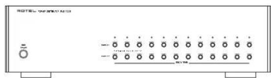
Figure 1: Controls and Connections
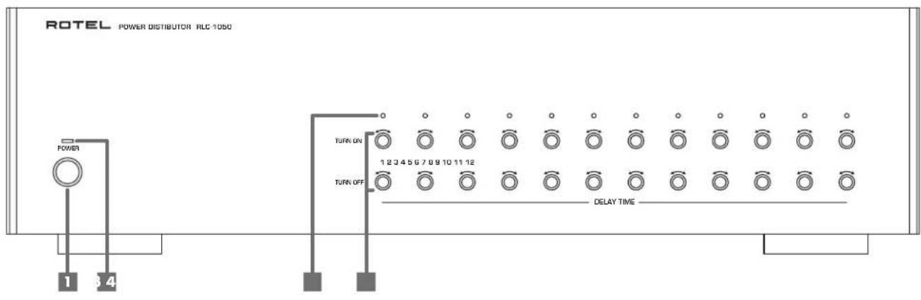
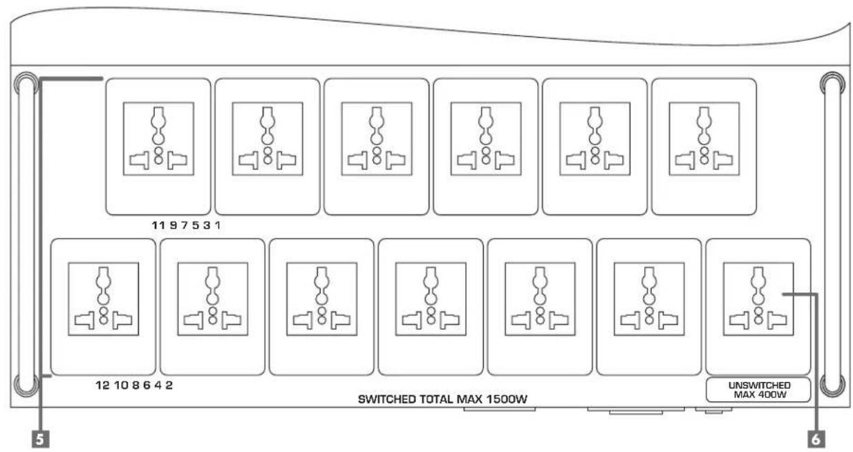
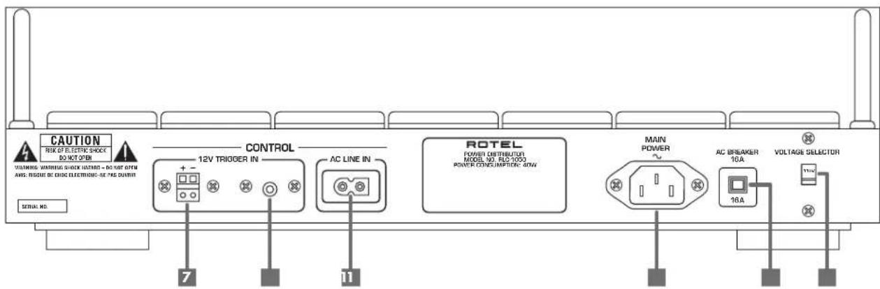
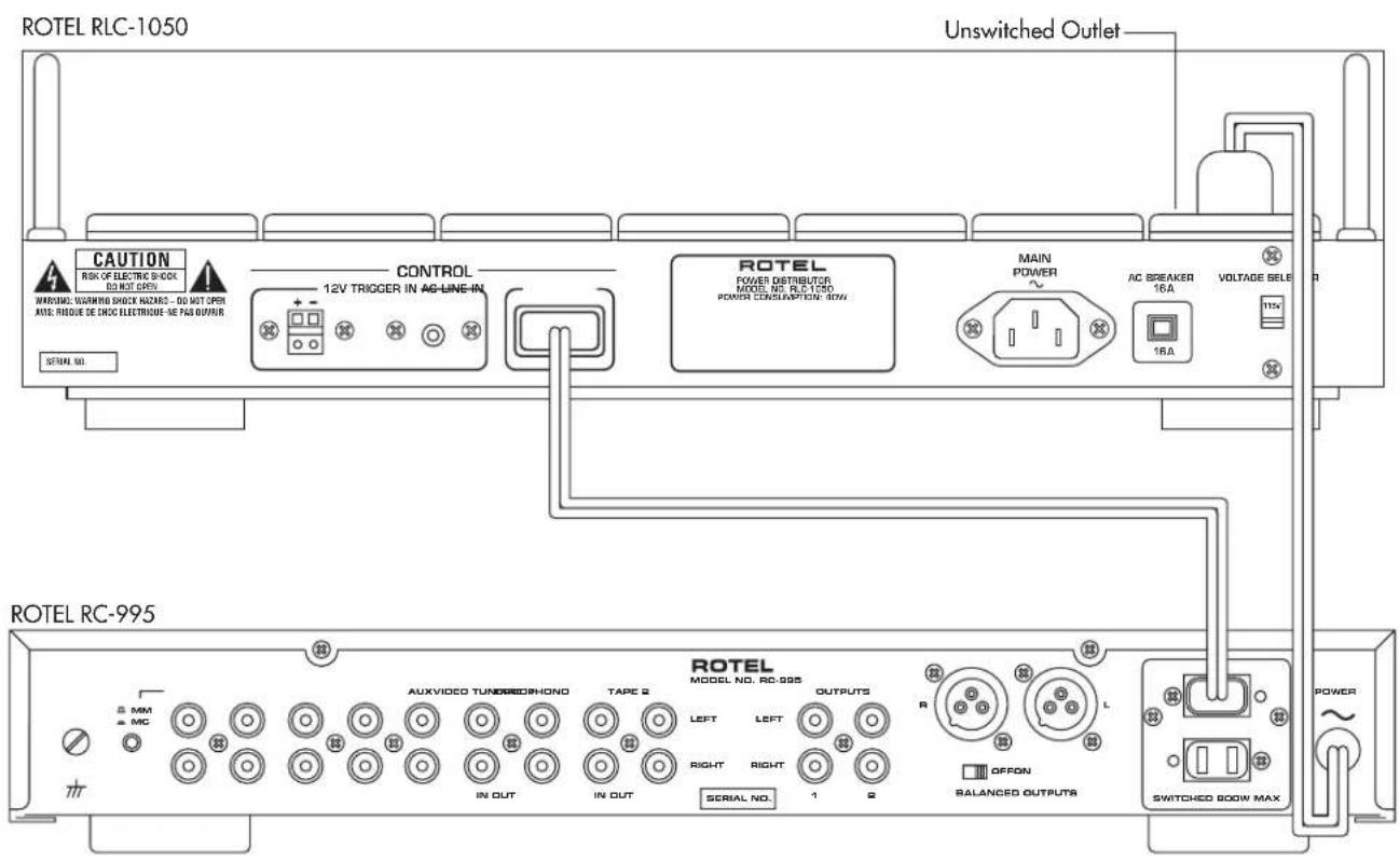
Figure 2: Control Cord Connection
5 English
Contents
Figure 1: Controls and Connections ..... 3
Figure 2: Control Cord Connection...... 4
About Rotel 5
Getting Started 5
A Few Precautions 6
Placement 6
Cables 6
Power Input and Control.... 6
Power Mains Voltage Switch 62
Main Power Input 80
Power Switch and Power Indicator 6 2
AC Line In Control Cord 69
12V Trigger In and 6 8
Switched Power Outlets 5......7
Turn-On Delay Controls and
Turn-Off Delay Controls 4 7
Power Indicators 3 7
Unswitched Outlet 6 7
Circuit Breaker 11....7
Troubleshooting 7
About Rotel
A family whose passionate interest in music led them to manufacture high fidelity components of uncompromising quality founded Rotel over 30 years ago. Through the years that passion has remained undiminished and the family goal of providing exceptional value for audiophiles and music lovers, regardless of their budget, is shared by all Rotel employees.
The engineers work as a close team, listening to, and fine tuning each new product until it reaches their exacting musical standards. They are free to choose components from around the world in order to make that product the best they can. You are likely to find capacitors from the United Kingdom and Germany, semi conductors from Japan or the United States, while toroidal power transformers are manufactured in Rotel's own factory.
Rotel's reputation for excellence has been earned through hundreds of good reviews and awards from the most respected reviewers in the industry, who listen to music every day. Their comments keep the company true to its goal – the pursuit of equipment that is musical, reliable and affordable.
All of us at Rotel thank you for buying this product and hope it will bring you many hours of enjoyment.
Getting Started
Thank you for purchasing the Rotel RLC-1050 Power Distributor. We are confident that the RLC-1050 will enhance the performance of your audio system for years to come.
The RLC-1050 solves several problems that are common in multi-components systems. The power control features of the RLC-1050 make it easy to turn on and off all the components in the system. Furthermore each outlet has separate turn-on delay and turn-off delay controls. The delay for each control can be adjusted from 1 to 30 seconds. By setting the controls so that the system components turn on and off in the proper sequence, turn-on and turn-off thumps noises can be prevented.
The RLC-1050 can be set to work with either 115V/60Hz or 230/50Hz AC power systems. It has universal power outlets that can accept virtually any kind of power plug.
The power outlets are also heavily filtered to minimize the potentially damaging effects of power line spikes.
The RLC-1050 also ensures efficient component operation by isolating them from performance-robbing lower level surges, RFI, and EMI. The RLC-1050 is proof that Rotel's Balanced Design approach extends to your whole system.
A Few Precautions
Please read this manual carefully. It provides complete information on how to incorporate the RLC-1050 into your system as well as general information that will help you get the greatest benefit from it. Keep this manual for future reference. Please contact your authorized Rotel dealer for answers to any questions you might have. In addition, all of us at Rotel welcome your questions and comments.
The RLC-1050 can be set to work with either 115V/60Hz or 230/50Hz AC power systems. See the "Power Mains Voltage Switch" section of this manual for more information.
Do not use an extension cord or power strip to provide power to the RLC-1050. Plug it directly into a wall outlet.
When unplugging the RLC-1050, or any other electrical device, do not pull on the power cord. Grasp the power cord plug and pull it straight out of the wall.
Do not plug an extension cord into the RLC-1050 to provide extra outlets. Under no circumstances should the total power requirements of the components plugged into the RLC-1050 exceed 1500 watts. If you have questions, consult your authorized Rotel dealer.
Be certain to make all power and audio connections in the system before turning the RLC-1050 on for the first time.
Save the RLC-1050 shipping carton and all enclosed packing material for future use. Shipping or moving the RLC-1050 in anything other than the original packing material may result in severe damage.
Fill out and send in the owner's registration card packed with the RLC-1050. Also be sure to keep the original sales receipt. It is your best record of the date of purchase, which you will need in the event warranty service is ever required.
Placement
Like all electrical components, the RLC-1050 can be affected by its environment and can affect other components. Do not place the RLC-1050 on top of other components, and do not place other components on top of it. This will minimize chance that the other components will pick up hum or interference.
Do not place the RLC-1050 where it will be exposed to direct sunlight, excessive dust, humidity or moisture, heat or cold.
We recommend installing the RLC-1050 in furniture designed to house audio components. Such furniture is designed to reduce or suppress vibration, which can adversely affect sound quality. Ask your authorized Rotel dealer for advice about component furniture and proper installation of audio components.
Cables
Be sure to keep the power cords, digital signal cables and regular audio signal cables in your installation away from each other. This will minimize the chance of the regular audio signal cables picking up noise or interference from the power cords or digital cables. Using only high quality, shielded cables will also help to prevent noise or interference from degrading the sound quality of your system. If you have any questions see your authorized Rotel dealer for advice about the best cable to use with your system
Power Input and Control
Power Mains Voltage Switch 12
NOTE: Do not change the setting of the Power Mains Voltage Switch.
The RLC-1050 is set at the factory for the power mains voltage for the country in which it is sold. There are components inside the RLC-1050 that are designed to work with specific mains voltage. So you cannot switch the RLC-1050 to work with a different power mains voltage.
Main Power Input 10
Connect the supplied power cord to the Main Power Input. Plug the power cord directly into a wall power outlet. Do not use extension cords or power strips. The outlet must be capable of providing 15 amps of current.
Power Switch 1nd Power Indicator 2
Push in the power switch 1 to turn on the RLC-1050. Power is not applied to the Switched Power Outlets until they are activated by either the AC Line In Control Cord or the 12V Trigger In. See the following sections. When the Switched Power Outlets are activated the Power Indicator 2 is lit.
AC Line In Control Cord 9
One way to activate the Switched Power Outlets is to apply power to the AC Line In Control Cord on the rear panel. This feature allows you to use a switched outlet on another component, typically a preamplifier, to turn on the power to the rest of the system. See Figure 2. If you do not use this feature, or the 12V Trigger Input, to activate the Switched Outlets of the RLC-1050, the Control Cord must be plugged into the Unswitched Outlet on the RLC-1050 rear panel.
12V Trigger In 7nd 8
Another way to activate the Switched Outlets of the RLC-1050 is to apply a turn on voltage signal to one of the 12V Trigger In connectors. When a turn on voltage signal is applied to one of the 12V Trigger In connectors the Switched Outlets of the RLC-1050 are activated, even if the front panel power button has not been pressed.
The turn on voltage signal may be AC or DC and can range from 3 volts to 30 volts. Many components can provide a turn on voltage trigger signal when they are turned on. Both a bare wire connector 7 and a mini-plug type connector 8 are provided.
When using the bare wire connector with a DC trigger signal be sure to maintain proper polarity. Connect positive to positive and negative to negative.
7 English
Switched Power Outlets 5
There are 12 switched AC outlets on the rear panel that are controlled by the RLC-1050. In addition there is one unswitched outlet. Each of the switched outlets has separate turn-on delay and turn-off delay controls. The outlets on the RLC-1050 are a "universal" type which will accept virtually any type of power plugs.
NOTE: The RLC-1050 can provide up to 1500 watts of power. All electrical devices list the amount of power they will draw on the back panel. Add up the wattage of all the components that will be connected to the RLC-1050 to be sure it does not exceed 1500 watts.
Turn-On Delay Controls and Turn-Off Delay Controls 4
Each switched outlet of the RLC-1050 has separate turn-on delay and turn-off delay controls. The delay for each control can be adjusted from 1 to 30 seconds. When the controls are turned all the way counterclockwise the delay is only 1 second. When the controls are turned all the way clockwise the delay is 30 seconds.
By setting the controls so that the system components turn on and off in the proper sequence, turn-on and turn-off thumps noises can be prevented.
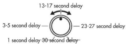
Signal sources such as CD players should be turned on first. Set the Turn-On Delay Controls for these components for 1 second delay. Components such as signal processors should be turned on next. Set the Turn-On Delay Control for these components to provide a somewhat greater turn on delay. Amplifiers should be turned on last, and so should have the greatest amount of turn on delay. That does not mean that the Turn-On Delay Control for the amplifier must be at the maximum setting. A delay of 10-15 seconds may be enough to prevent turn on noises.
NOTE: Amplifiers can draw large amounts of power. A high power amplifier can draw more power than the RLC-1050 can handle. Do not connect components to the RLC-1050 that will require more than 1500 watts total.
Generally the components should be turned off in the reverse order they are turned on. Amplifiers should be turned off first and signal sources last. Components that have short turn-on delays should have long turn-off delays. Components that have long turn-on delays should have short turn-off delays.
Power Indicators 3
The Power Indicators for each switched outlet light when power is applied to the outlet. These indicators provide a visual indication of the sequence in which the various power outlets are turned on and off.
Unswitched Outlet 6
The unswitched outlet may be used in one of two ways. If the Switched Outlets of the RLC-1050 are not activated with either the AC Line In Control Cord or the 12V Trigger In, it must be connected to the Unswitched outlet. Otherwise the RLC-1050 Switched Outlets will not be activated. If one of the two control systems is used to activate the RLC-1050 switched outlets, the Unswitched Outlet may be used to supply power to a component that should always be powered.
NOTE: Do not connect a component that requires more than 400 watts to the Unswitched outlet.
Circuit Breaker 11
If the components connected to the RLC-1050 draw more power than it can safely deliver, or if there is a short circuit in one of the power lines of one of the components, the Circuit Breaker will be tripped. If this occurs, turn off the RLC-1050 and check to be sure the total power requirements of the components connected to the RLC-1050 does not exceed 1500 watts.
If the power requirements of the connected components is not greater than 1500 watts the circuit breaker being tripped might indicate a problem in one of the components. Try the following test to isolate a potentially defective component. First, turn off all the connected components with their built-in power switches. Turn on the RLC-1050 and activate the Switched Power Outlets. Then turn on the components connected to the RLC-1050 one by one. Turn them on in the same order they would be turned on by the RLC-1050 – signal sources first, amplifier last. If the Circuit Breaker is tripped as soon as a component is turned on it indicates a problem with that component.
Troubleshooting
Most difficulties are the result of incorrect connections, or improper control settings. The Main Power Indicator should be lit whenever the RLC-1050 is plugged into the wall power outlet, and the Main Power Switch is pushed. If it does not light, test the power outlet that the Main Power cord of the RLC-1050 is plugged into with another electrical device, such as a lamp. Be sure the power outlet being used is not controlled by a switch that has been turned off.
natural_image
Close-up of a printed circuit board with various electronic components and traces (no readable text or symbols)
The Rotel Co. Ltd.
10-10 Shinsen-Cho
Shibuya-Ku
Tokyo 150-0045
Japan
Phone: +81 3-5458-5325
Fax: +81 3-5458-5310
Rotel of America
54 Concord Street
North Reading, MA 01864-2699
USA
Phone: +1 978-664-3820
Fax: +1 978-664-4109
Rotel Europe
Meadow Road
Worthing, West Sussex BN11 2RX
England
Phone: +44 (0)1903 524 813
Fax: +44 (0)1903 524 831
Rotel Deutschland
Kleine Heide 12
- Owner's Manual
- RLC-1050
- Power Distributor
- English
- Contents
- About Rotel
- Getting Started
- A Few Precautions
- Placement
- Cables
- Power Input and Control
- Power Mains Voltage Switch 12
- Main Power Input 10
- Power Switch 1nd Power Indicator 2
- AC Line In Control Cord 9
- 12V Trigger In 7nd 8
- English
- Switched Power Outlets 5
- Turn-On Delay Controls and Turn-Off Delay Controls 4
- Power Indicators 3
- Unswitched Outlet 6
- Circuit Breaker 11
- Troubleshooting
Brand : ROTEL
Model : RLC-1050
Category : Module d'extension