
F14 - Thermometer AGM - Free user manual and instructions
Find the device manual for free F14 AGM in PDF.


| Type of Product | Thermometer |
| Brand | AGM |
| Model | F14 |
| Product Category | Medical / Industrial Thermometer |
| Dimensions (Approx.) | 150 x 30 x 20 mm |
| Weight (Approx.) | 50 g |
| Power Source | 2 x AAA batteries |
| Display Type | LCD digital display |
| Measurement Range | -50°C to 300°C (-58°F to 572°F) |
| Accuracy | ±1°C (±1.8°F) within 0-100°C |
| Response Time | < 1 second |
| Units of Measurement | Celsius / Fahrenheit selectable |
| Key Features | Instant reading, auto-off, hold function, low battery indicator |
| Intended Use | Body temperature (clinical) or surface temperature |
| Cleaning and Maintenance | Wipe probe with alcohol swab after each use; store in dry place |
| Safety Precautions | Keep away from water immersion; do not use if damaged. |
| Battery Replacement | Replace when low battery icon appears; use alkaline batteries. |
| Spare Parts Availability | Batteries and probe covers available separately |
| Repairability | No user-serviceable parts; contact AGM support for repairs. |
| Certifications | CE, RoHS compliant |
Frequently Asked Questions - F14 AGM
User questions about F14 AGM
0 question about this device. Answer the ones you know or ask your own.
Ask a new question about this device
Download the instructions for your Thermometer in PDF format for free! Find your manual F14 - AGM and take your electronic device back in hand. On this page are published all the documents necessary for the use of your device. F14 by AGM.
USER MANUAL F14 AGM
F14
FUSION NIGHT VISION
TACTICAL MONOCULAR
© 2021 AGM Global Vision, LLC. All rights reserved.
This documentation is subject to change without notice.
No parts of this manual, in whole or in part, may be copied, photocopied, translated, or transmitted by any electronic medium or in machine-readable form without the prior written permission of AGM Global Vision, LLC.
If you have questions that are not covered in this manual, or need service, contact AGM Global Vision customer support for additional information prior to returning a product.
AGM Global Vision, LLC
173 West Main Street
PO Box 962
Springerville, AZ 85938
Tel. 928.333.4300
support@agmglobalvision.com
www.agmglobalvision.com
EXPORT INFORMATION
Buyer acknowledges that all products supplied by AGM Global Vision, LLC are subject to U.S. export control laws, including, but not limited to, the Export Administration Regulations, the International Economic Emergency Powers Act, and various U.S. embargoes and sanctions. AGM Global Vision products may not be exported, re-exported, or transferred contrary to U.S. export control laws. In particular, AGM Global Vision products may not be exported, re-exported, or transferred to prohibited countries, individuals, organizations, or entities, including but not limited to those individuals and entities listed on the List of Specially Designated Nationals and Blocked Persons administered or maintained by the U.S. Office of Foreign Assets Control ("OFAC"), the various lists maintained by the Bureau of Industry and Security of the Department of Commerce, and the U.S. State Department and Buyer represents and warrants that neither Buyer nor any of its officers, directors, or employees are on such lists. Distribution or resale by Buyer to such countries, individuals, organizations, or entities is expressly prohibited. Buyer has and will maintain a positive process to ensure compliance with this Section.
FCC INFORMATION
Please take attention that changes or modification not expressly approved by the party responsible for compliance could void the user's authority to operate the equipment.

This equipment complies with FCC/IC RSS-102 radiation exposure limits set forth for an uncontrolled environment.
FCC compliance: This product has been tested and found to comply with the limits for a Class B digital device, pursuant to Part 15 of
the FCC Rules. These limits are designed to provide reasonable protection against harmful interference in a residential installation. This product generates, uses, and can radiate radio frequency energy and, if not installed and used in accordance with the instructions, may cause harmful interference to radio communications. However, there is no guarantee that interference will not occur in a particular installation. If this product does cause harmful interference to radio or television reception, which can be determined by turning the equipment off and on, the user is encouraged to try to correct the interference by one or more of the following measures:
- Reorient or relocate the receiving antenna.
— Increase the separation between the equipment and receiver. - Connect the equipment into an outlet on a circuit different from that to which the receiver is connected.
— Consult the dealer or an experienced radio/TV technician for help.
FCC Conditions
This device complies with part 15 of the FCC Rules. Operation is subject to the following two conditions:
- This device may not cause harmful interference.
- This device must accept any interference received, including interference that may cause undesired operation.
EU CONFORMITY STATEMENT
This product and - if applicable - the supplied accessories too are marked with "CE" and comply therefore with the applicable harmonized European standards listed under the EMC Directive 2014/30/EU, the RoHS Directive 2011/65/EU
2012/19/EU (WEEE directive): Products marked with this symbol cannot be disposed of as unsorted municipal waste in the European Union. For proper recycling, return this product to your local supplier upon the purchase of equivalent new equipment, or dispose of it at designated collection points. For more information see: www.recyclethis.info
2006/66/EC (battery directive): This product contains a battery that cannot be disposed of as unsorted municipal waste in the European Union. See the product documentation for specific battery information. The battery is marked with this symbol, which may include lettering to indicate cadmium (Cd), lead (Pb), or mercury (Hg). For proper recycling, return the battery to your supplier or to a designated collection point. For more information see: www.recyclethis.info
INDUSTRY CANADA ICES-003 COMPLIANCE
This device meets the CAN ICES-3 (A)/NMB-3(A) standards requirements.
LIST OF CONTENTS
TITLE
Safety Summary 5
1. GENERAL INFORMATION 6
1.1 System Description 6
1.2 Standard Components 7
1.3 Key Features 8
2. OPERATING INSTRUCTIONS 9
2.1. Basic Operations 9
2.2 Main Function 12
2.3 Client Software Introduction 17
3. MAINTENANCE 19
3.1 Maintenance 19
3.2 Troubleshooting 20
4. WARRANTY INFORMATION 21
4.1 Warranty Information and Registration 21
5. SPECIFICATIONS 23
5.1 Specifications 23
SAFETY SUMMARY
- Read and follow all instructions
- Read all warnings
- Only use the attachments/accessories specified by the manufacturer
- All service must be provided by the manufacturer
WARNING:
This product contains natural rubber latex, which may cause potentially fatal allergic reactions! If you are allergic to latex, it is important that you strictly avoid exposure to products that contain it.
WARNINGS AND CAUTIONS:
- All electronic operation should be in strict compliance with the electrical safety regulations, fire prevention regulations and other related regulations in your local region.
- Please use the power adapter, which is provided by a proven manufacturer. The power consumption cannot be less than the required value.
- Do not connect several devices to one power adapter as adapter overload may cause over-heat or fire hazard.
- Do not drop the device or subject it to physical shock, and do not expose it to high electromagnetism radiation. Avoid the device installation on vibrations surface or places subject to shock (ignorance can cause equipment damage).
- Do not place the device in extremely hot (refer to the specification of the device for the detailed operating temperature), cold, dusty or damp locations, and do not expose it to high electromagnetic radiation.
- The device cover for indoor use should be kept from rain and moisture.
- Exposing the device to direct sun light, low ventilation or heat source such as heater or radiator is forbidden (ignorance can cause fire danger).
- Do not aim the device at the sun or extra bright places. A blooming or smear may occur otherwise (which is not a malfunction however), and affecting the endurance of sensor at the same time.
- For long-term storage of the battery, make sure you fully charge it every 6 months, to ensure the battery quality. Otherwise, you may damage the battery.
NOTES:
The detector spectral band provides better visibility through smoke, dust, rain, smog, etc.
Infrared radiation does not travel through glass. As a result, the monocular does not detect objects if they are behind glass windows or other barriers.
1 GENERAL INFORMATION
1.1 SYSTEM DESCRIPTION
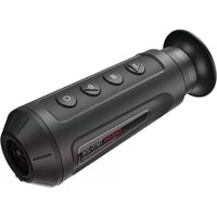
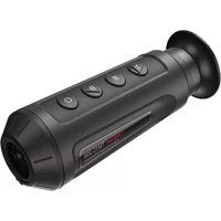
The AGM F14 Fusion Night Vision Tactical Monocular combines I2 and thermal imaging technologies. The F14 bi-spectrum monocular is a device that can observe and search targets at night, in darkness, under extreme environments such as smoke, fog, rain, snow, etc. It can be widely applied to scenarios including patrol, search and rescue, drug interdiction, and suspect apprehension. Due to its waterproof capability the device performs well even in severe weather conditions and challenging environments.
The AGM F14 can be outfitted with either a Gen 2+ or Gen 3 high-performance image intensifier tube (IIT) and 12μm high sensitivity thermal detector with 640x512 resolution. The F14 can be used as handheld device or mounted on a helmet. The user-friendly interface, comfortable and ergonomic operating controls makes adoption and application of the device incredibly simple. The device offers different variants of image view: thermal, I² night vision, and enhanced fusion image that can be easily adapted depending on different environmental conditions. The F14 is also equipped with manual gain control, which adjusts the image brightness, providing the highest possible image quality even in changing light conditions. The monocular uses two 18650 rechargeable Lithium battery in the external holder for up to 8-hours of operating time in fusion image mode. In I² night vision mode device can run more than 60 hours.
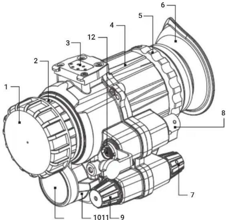
FIGURE 1-1. MAIN PARTS
TABLE 1-1. MAIN PARTS
| ITEM DESCRIPTION ITEM DESCRIPTION | |||
| 1 Objective lens hood 7 I | 2 switch/Adjusting knob | ||
| 2 | I2 objective lens 8 Fill-in light switch | ||
| 3 Quick removal interface 9 | Infrared switch/Adjusting knob | ||
| 4 Device body 10 Infrared objective lens | |||
| 5 | Ocular lens | 11 | Infrared lens hood |
| 6 Eye cup 12 Aviation plug | |||
1.2 STANDARD COMPONENTS
The standard components are shown in Figure 1-2 and listed in Table 1-2. The ITEM NO. column indicates the number used to identify items in Figure 1-2.

FIGURE 1-2. STANDARD COMPONENTS
TABLE 1-2. STANDARD COMPONENTS
| ITEM | DESCRIPTION QUANTITY | |
| 1 | Monocular | 1 |
| 2 | Battery holder | 1 |
| 3 | Helmet support | 1 |
| 4 | Battery holder interface with hook-loop support | 1 |
| 5 | 18650 rechargeable Lithium battery | 2 |
| 6 | Eye cup | 1 |
| 7 | Video cable | 1 |
| 8 | Operation manual | 1 |
| 9 | Packing case | 1 |
1.3 KEY FEATURES
- Bi-spectrum image fusion and object highlight
• Detail enhancement and target recognition - Selection of thermal view channel, I 2 night vision channel, or both them combined with multiple fusion modes switchable
• 12μm, 640x512 high sensitivity thermal detector
• Digital zoom in thermal channel - Azimuth and pitch/inclination indication
- Brightness and contrast image adjustment
• Extra large exit pupil diameter (15mm) - Low cower consumption
- Up to 8 hours continuous running in fusion mode and more then 60 hours operation in I 2 night vision mode
• Aviation plug for external power supply and video output - Waterproof
- Limited 3-year warranty
2 OPERATING INSTRUCTIONS
2.1. BASIC OPERATIONS
2.1.1 UNPACKING
The following steps must be completed prior to each mission.
- Open the carrying case, remove the monocular, and verify that all components are included.
- Inspect the monocular for any obvious evidence of damage to the optical surfaces, body, eyecup, operation buttons, etc. Ensure that all optical surfaces are clean and ready for use. Clean all optical surfaces with a lens tissue.
2.1.2 BATTERY HOLDER COMPONENTS AND THEIR FUNCTIONS

FIGURE 2-1. BATTERY HOLDER COMPONENTS
TABLE 2-1. BATTERY HOLDER COMPONENTS
| ITEM COMPONENT FUNCTION DESCRIPTION | ||
| 1 Battery Two 18650 rechargeable Lithium batteries. | ||
| 2 | Battery compartment cover | Enables battery assembly and disassembly, and seals the compartment. |
| 3 Quick removal interface | Connects to the interfaces for installing the hook-loop support. | |
| 4 Disassembly pull | Pull it out when disassembling the battery holder. | |
| 5 Master power switch Powers on/off the equipment. | ||
| 6 | Image transmission power switch | Powers on/off the image transmission module. |
| 7 | Aviation plug Video and signaling transmission. | |
| 8 | Aviation plug cover Prevents water or dust. | |
| 9 | Body | Provides sealing and prevents water or dust. |
2.1.3 COMPONENTS OF THE HELMET SUPPORT AND THEIR FUNCTIONS

FIGURE 2-3. COMPONENTS OF THE HELMET SUPPORT
TABLE 2-2. COMPONENTS OF THE HELMET SUPPORT
| ITEM COMPONENT FUNCTION DESCRIPTION | ||
| 1 | Hook-loop support of the battery holder | Fixes the battery holder on the helmet. |
| 2 | Battery holder interface Connects to the battery holder. | |
| 3 | Goggle interface Connects to the main body of the goggle. | |
| 4 | Power cable Provides power supply. | |
| 5 | Helmet installation interface | Fixes the helmet support on the shroud. |
| 6 | Horizontal fine-tuning buckle | Adjusts the horizontal position of the goggle. |
| 7 | Pitch fine-tuning knob | Adjusts the pitch angle of the goggle. |
| 8 | Front-back tuning buckle | Adjusts the front and back position of the goggle. |
| 9 | Fixing screw for switching between eyes | Fixes the goggle either at the right or left eye. |
| 10 | Vertical tuning screw | Adjusts the vertical position of the goggle. |
2.1.4 ASSEMBLY/DISASSEMBLY
You can use F14 in two modes: handheld or mounted on a helmet. Assemble the equipment as instructed after you decide how to use it.
Before use, install the batteries. F14 uses two 18650 lithium-ion batteries. The installation procedure is as follows:
Unscrew the two covers of the battery compartments.
Check the polarity of the batteries and place the batteries into the designated position with the correct polarity.
Tighten the covers of the battery compartments.

FIGURE 2-4. INSTALLING THE BATTERIES FOR F14
In handheld use, no helmet support is required. What you need are the main body of the goggle and the battery holder. The procedure for installing F14 for handheld use is as follows:
Take out the main body of the goggle and the battery holder.
Install the ocular lens hood if needed.
Align the broad side of the battery holder with that of the goggle in the correct direction.
Press the battery holder until it clicks and the assembly is completed.
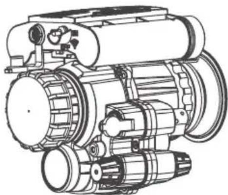
FIGURE 2-5. F14 FOR HANDHELD USE
The procedure for disassembling handheld F14 is as follows:
Turn off the infrared I2 switch of the goggle and the main power of the battery holder.
Pull out the disassembly pull of the battery holder and lift it upward.
Separated the battery compartment and the main body of the goggle.

FIGURE 2-6. DISASSEMBLING HANDHELD F14
When using this equipment on a helmet, you need to fix the helmet support on the helmet. F14 is compatible with various multi-functional shrouds and hook-loop helmets. The procedure for installing a helmet-based F14 is as follows: Install the helmet support on the shroud.

FIGURE 2-7. F14 USED ON A HELMET
Attach the hook-loop support of the battery holder to the hook-loop fastener in the middle of the rear part of the helmet.
Align the broad side of the battery holder with that of the hook-loop support. Press the battery holder until it clicks.
Connect the power cable of the hook-loop support and the helmet support, with the female and male white points aligned.
Install the ocular lens hood on the main body of the goggle if needed.
Align the broad side of the quick removal interface with that of the goggle interface on the helmet support. Then lift the main body of the goggle upward until it clicks.
The procedure for disassembling helmet-mounted F14 is as follows:
Turn off the power: Turn off the infrared I2 switch of the goggle and the main power of the battery holder.
Remove the main body of the goggle: Turn the quick-removal knob on the helmet support and pull out the main body of the goggle downward.
Remove the battery compartment: Pull out the disassembly pull of the battery holder and lift it upward. The battery holder is removed from the hook-loop support.
Disconnect the power cable: Fix the female connector of the hook-loop support and pull out the male connector of the power cable of the helmet support.
Disassemble the hook-loop support.
Disassemble the helmet support: Press the snap ring of the holder and pull out the helmet support.
2.1.5 POWER-UP AND USE
Before powering up the equipment, turn on the main power of the battery holder.
Then enable I2 night vision, turn on the infrared switch, and enable infrared thermal image night vision. You will see fused images in the ocular lens.
2.2 I² NIGHT VISION
2.2.1 ENABLING I 2 NIGHT VISION
After turning on the main power of the battery holder, turn the I 2 knob from OFF to MAX until you hear clicking. Then this function is enabled and you can observe I2 images in the ocular lens. Continue turning the I 2 knob towards MAX to adjust the image brightness as required.
CAUTION:
After enabling I2 night vision, avoid exposing the equipment under direct high light. If you use it in scenarios with sufficient light, cover the I2 objective lens with a hood so as to protect its components from damage.
2.2.1 PROTECTION AGAINST HIGH LIGHT
I2 components are vulnerable under high light. Therefore, F14 has added highlight protection. When detecting that I2 components are exposed to high light for a long time, the equipment will automatically disable the I2 night vision function.
When excessively strong ambient light is detected, you will see a red indicator blinking (interval: 1s) in the right corner of the screen through the ocular lens. If the high light persists, I 2 power will be turned off after 1 minute so that the components are not damaged.
To observe targets under high light or through the small hole of the I 2 objective lens cap, long press the fill-in light switch to disable high-light protection. The indicator then turns steady blue. To enable high-light protection, long press the fill-in light switch. Then the blue indicator turns off.
NOTE:
Each time you enable I2 , high-light protection is enabled by default.
2.2.1 POWER-OFF BY UPTURNING THE SUPPORT
When using F14 by mounting it on a helmet support, you can power off the equipment by upturning the support. This reduces power consumption and possible damage to I2 components due to direct exposure to sunlight or other light sources.
Turn on the main power of the battery compartment and turn the infrared knob from OFF towards MAX until you hear clicking. Then infrared night vision is enabled. You can see the start-up logo "F14" and observe infrared thermal images after 3-5 seconds in the ocular lens. Continue turning the infrared knob towards MAX to adjust the brightness of the infrared thermal image as required.
In infrared night vision mode, you can short press the l2 knob to zoom in on the infrared image.
NOTE:
When the external video is connected, "PIP of external video" and "Full screen of external video" are available.
NOTE:
You cannot switch to enhanced mode if only infrared night vision is enabled.
2.4 SHUTTER CORRECTION
If infrared images experience noise, deterioration, or bright spots after you enable infrared night vision, you need to correct the shutter manually. Long press the I2 knob for 2s to manually correct the shutter. You can hear the shutter click during the correction. The correction time is less than 1s.
When I2 night vision and infrared night vision are enabled at the same time, you can observe enhanced night vision images from the ocular lens. You can switch among a variety of enhanced display modes as needed.
2.5.1 SWITCHING ENHANCED NIGHT VISION MODES
In the enhanced night vision mode, short press the I 2 knob to switch the enhanced modes. F14 has four enhanced display modes: Outline, Target highlight, Thermal image, and Breathing alert. Short press the I 2 knob to switch between the four display modes cyclically.
CAUTION:
When the external video is connected, "PIP of external video" and "Full screen of external video" are available.
NOTE:
The Outline mode is the default mode after the enhanced night vision is enabled.
2.5.2 SWITCHING THERMAL POLARITY IN ENHANCED NIGHT VISION MODE
In the enhanced night vision mode, short press the infrared adjusting knob to switch the infrared thermal polarity. That is, it switches among White-hot, Black-hot, and Orange-hot.
NOTE:
There are only White-hot and Orange-hot polarities in Outline and Target highlight modes.
In the totally dark scenario, the I 2 night vision should be used with the fill-in light turned on. You can turn the switch from OFF to ON to turn on the fill-in light. Then, the red indicator is steady on, which can be seen in the ocular lens, reminding you that the infrared fill-in light has been turned on.
2.6 INTERFACE INFORMATION
When infrared night vision or enhanced night vision mode is enabled, the interface of F14 is shown in Figure 2.8 and the icon descriptions are shown in Table 2.3.
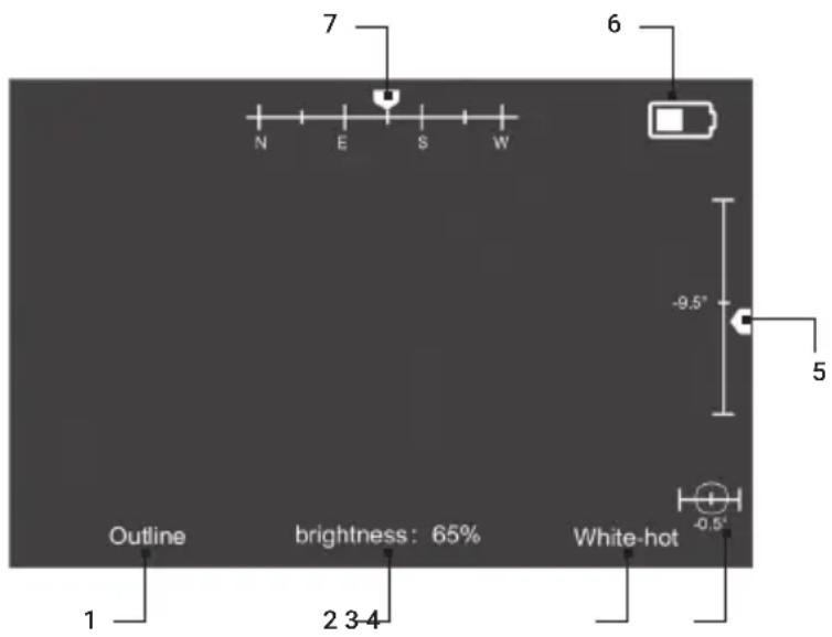
FIGURE 2-8. F14 SCREEN INTERFACE
TABLE 2-3. ICON DESCRIPTION
| ITEM ICON DESCRIPTION | ||
| 1 Enhanced display mode | Outline, Target highlight, Thermal image, and Breathing alert modes (When external videos are connected, “PIP of external video” and “Full screen of external video” modes are also available.) | |
| 2 | Brightness of the infrared thermal image | Infrared brightness 0% to 100%. |
| 3 Infrared polarity White-hot, black-hot, and orange-hot. | ||
| 4 Inclination angle -90° to +90° | ||
| 5 Pitch angle -90° to +90° | ||
| 6 Battery level | 0-4 levels: When the battery power reaches Level 0, it indicates that the power is below 10%, so you should recharge or replace the battery as soon as possible. | |
| 7 Azimuth | The scale arrow moves to indicate the direction the ocular lens is facing. | |
2.7 MENU AND SETTINGS
2.7.1 DISPLAYING THE MENU
Long press the infrared adjusting knob for 2s. The menu is displayed. You can turn on or off the analog video output, compass calibration, azimuth angle, pitch angle, and inclination angle.

FIGURE 2-9. MENU
After the menu is displayed, short press the infrared adjusting knob to switch among menu options and long press the knob to enable/disable an option (in the mode shown in Figure 2.9, you can short press and the arrow switch to the "Compass calibration" option, and long press it to turn on/off analog video).
When switching to the "Exit" option, long press the infrared adjusting knob to exit the menu.
2.7.3 OUTLINE THRESHOLD
The outline threshold specifies how much detail is displayed in the outline mode, and the range of threshold is 1-5. The higher the threshold, the more outline details are displayed. You can set it as required.
When the cursor points to the "Outline threshold" option, long press the infrared adjusting knob to set this option. At this time, the threshold in brackets is in an inverted color and can be adjusted among 1 to 5 (ascending). You can short press the infrared adjusting knob to select the required threshold. After selecting the required threshold, long press the infrared adjusting knob to exit the "Outline threshold" option.
NOTE:
It is recommended to adjust the outline threshold in the outline mode, and observe the change of outline details corresponding to different thresholds in real time.
2.7.4 PAL VIDEO
You can turn on/off the analog video (PAL) output of the goggle through this option. The analog video output needs to use the designated cable, and the infrared video can be displayed on the monitor connected by this cable. When switching to the "PAL video" option, long press the infrared adjusting knob to turn on/off the PAL video.
But it is recommended to turn it off if you don't need to output the analog video, thereby saving power and prolonging the service time.
2.7.5 COMPASS CALIBRATION
The digital magnetic compass can indicate the azimuth angle, pitch angle, and inclination angle of the equipment. In view of the differences in different regions and altitudes, you need to calibrate the compass after you move to another place to ensure the indication accuracy of the compass.
Steps:
When the menu is displayed, switch to compass calibration.
Long press the infrared adjusting knob to enter the calibration state and the screen displays "Please keep the equipment level and rotate at a constant speed. Press again to start."
Horizontal calibration: Put the equipment horizontally and short press the infrared adjusting knob. Rotate around the equipment for 360° and short press the knob to end horizontal calibration.

FIGURE 2-10. HORIZONTAL ROTATION
After that, the screen displays "Please keep the equipment stable and erect downward at a constant speed. Press again to start."
![graph LR A["Camera"] --> B["Assembly"] B --> C["Motor"] C --> D["Assembly"]](/content/2026/05/835232/images/266ee9deac205323cf937acfb603d1b0d4fb3834d05b5a447f00260db77518f7.jpg)
FIGURE 2-11. VERTICAL ROTATION
Vertical calibration: Put the equipment horizontally on a table and short press the infrared adjusting knob. Erect the equipment at a constant speed (objective lens facing downward and ocular lens upward) and short press the knob again to end the calibration.
The screen displays "Calibration completed. Press again to exit." Short press the infrared adjusting knob and exit compass calibration.
NOTE:
To ensure the accuracy of compass calibration, please perform the calibration in a stable environment in one time.
2.7.6 INTERFACE INFORMATION
You can enable/disable the display of azimuth, pitch, inclination, and battery level on the screen by long pressing the infrared adjusting knob.
2.7.7 LANGUAGE
You can change the language of the interface by long pressing the infrared adjusting knob. See Figure 2.9 for the English menu.
3 MAINTENANCE
3.1 MAINTENANCE
3.1.1 CLEANING PROCEDURES
- Gently brush off any dirt from the body of the device using a clean, soft cloth.
- Moisten the cloth with fresh water and gently wipe down the external surfaces (except lenses).
- Dry any wet surfaces (except lenses) using another dry, clean, soft cloth.
- Using a lens brush, carefully remove all loose dirt from the lenses.
- Dampen a cotton swab with ethanol and slowly, gently wipe down the lenses. Clean the glass surfaces using circular movements, starting from the center of the lens and moving out towards the edge, without touching the lens holder. Change the cotton swab after each circular stroke. Repeat this step until the glass surfaces are clean.
- Clean the accessories with a soft brush (or cloth) dampened with soap and water.
3.1.2 PREPARING FOR EXTENDED STORAGE
CAUTION:
Thoroughly dry each item before placing them into the storage case.
To prepare the monocular for extended storage:
-
Clean the monocular and accessories.
-
Place all items into the storage case.
3.2 TROUBLESHOOTING
Table 3-1 lists the most common malfunctions that may occur with your equipment. Perform the tests, inspections, and corrective actions in the order they appear in the table.
This table does not list all the malfunctions that may occur with your device, or all of the tests, inspections, and corrective actions that may be necessary to fix them. If the equipment malfunction is not corrected by the suggested actions, or a problem occurs that is not listed in this table, please contact AGM Global Vision's Customer Support center or your retailer.
TABLE 3-1. TROUBLESHOOTING
| FAULT TEST OR CHECK TROUBLESHOOTING | ||
| The cover of battery holder cannot be screwed or keeps locked. | Check whether the battery is installed in the correct direction.Check whether there are sundries or chips around the knob of battery cover.Check whether the battery holder is damaged, worn or deformed.Check whether the battery holder is damaged or deformed. | Reinstall the 18650 battery.Clean the threads of battery cover and battery holder.Perform the high level maintenance.Perform the higher level maintenance. |
| Unable to power on | (a)Check whether the battery is installed, its direction is correct, and its power is sufficient.(b)Check whether the power supply switch of the battery holder is enabled. | (a)Replace a new battery and install it correctly according to the instructions in Chapter 2.(b)Switch on the main power of battery holder. |
| The I2 image fails to be displayed | (a)Check whether the I2 image is used in the completely dark conditions.(b)Check whether the I2 objective lens hood is opened.(c)Check whether the main power of battery holder is switched on.(d)Try to adjust the brightness of I2 image. | (a)Turn on the fill-in light when using the I2 image in the completely dark conditions.(b)Open or cover the objective lens hood as required.(c)Switch on the main power of battery holder.(d)Adjust the brightness of I2 image. |
| The infrared image fails to be displayed | (a)Check whether the infrared objective lens hood is opened.(b)Check whether the main power of battery holder is switched on.(c)Try to adjust the brightness of infrared image.(d)View whether the infrared lens is blocked by objects. | (a)Open or cover the objective lens hood.(b)Switch on the main power of battery holder.(c)Adjust the brightness of infrared image.(d)Remove the barriers. |
4 WARRANTY INFORMATION
4.1 WARRANTY INFORMATION AND REGISTRATION
4.1.1 WARRANTY INFORMATION
This product is guaranteed to be free from manufacturing defects in material and workmanship under normal use for a period of three (3) years from the date of purchase. In the event that a defect covered by the warranty below occurs during the applicable period stated above, AGM Global Vision, at its discretion, will either repair or replace the product; such action on the part of AGM Global Vision shall be the full extent of AGM Global Vision's liability, and the Customer's sole and exclusive reparation. This warranty does not cover a product if it has been (a) used in ways other than its normal and customary manner; (b) subjected to misuse; (c) subjected to alterations, modifications or repairs by the Customer or by any party other than AGM Global Vision without prior written consent of AGM Global Vision; (d) is the result of a special order or categorized as "close-out" merchandise or merchandise sold "as-is" by either AGM Global Vision or the AGM Global Vision dealer; or (e) merchandise that has been discontinued by the manufacturer and either parts or replacement units are not available due to reasons beyond the control of AGM Global Vision. AGM Global Vision shall not be responsible for any defects or damage that in AGM Global Vision's view are a result from the mishandling, abuse, misuse, improper storage or improper operation of the device, including use in conjunction with equipment that is electrically or mechanically incompatible with, or of inferior quality to, the product, as well as failure to maintain the environmental conditions specified by the manufacturer. This warranty is extended only to the original purchaser. Any breach of this warranty shall be enforced unless the customer notifies AGM Global Vision at the address noted below within the applicable warranty period.
The customer understands and agrees that except for the foregoing warranty, no other warranties written or oral, statutory, expressed or implied, including any implied warranty of merchantability or fitness for a particular purpose, shall apply to the product. All such implied warranties are hereby and expressly disclaimed.
4.1.2 LIMITATION OF LIABILITY
AGM Global Vision will not be liable for any claims, actions, suits, proceedings, costs, expenses, damages, or liabilities arising out of the use of this product. Operation and use of the product are the sole responsibility of the Customer. AGM Global Vision's sole undertaking is limited to providing the products and services outlined herein in accordance with the terms and conditions of this Agreement. The provision of products sold and services performed by AGM Global Vision to the Customer shall not be interpreted, construed, or regarded, either expressly or implied, as being for the benefit of or creating any obligation toward any third party of legal entity outside AGM Global Vision and
the Customer; AGM Global Vision's obligations under this Agreement extend solely to the Customer. AGM Global Vision's liability hereunder for damages, regardless of the form or action, shall not exceed the fees or other charges paid to AGM Global Vision by the customer or customer's dealer. AGM Global Vision shall not, in any event, be liable for special, indirect, incidental, or consequential damages, including, but not limited to, lost income, lost revenue, or lost profit, whether such damages were foreseeable or not at the time of purchase, and whether or not such damages arise out of a breach of warranty, a breach of agreement, negligence, strict liability, or any other theory of liability.
4.1.3 PRODUCT REGISTRATION
In order to validate the warranty on your product, the customer must complete and submit AGM Global Vision PRODUCT REGISTRATION FORM on our website (www.agmglobalvision.com/customer-support).
4.1.4 OBTAINING WARRANTY SERVICE
To obtain warranty service on your unit, the End-user (Customer) must notify the AGM Global Vision service department via e-mail. Send any requests to support@agmglobalvision.com to receive a Return Merchandise Authorization number (RMA). When returning any device, please take the product to your retailer, or send the product, postage paid and with a copy of your sales receipt, to AGM Global Vision's service center at the address listed above. All merchandise must be fully insured with the correct postage; AGM Global Vision will not be responsible for improper postage or merchandise that becomes lost or damaged during shipment. When sending product back, please clearly write the RMA# on the outside of the shipping box. Please include a letter that indicates your RMA#, the Customer's Name, a Return Address, reason for the return, contact information (valid telephone numbers and/or an e-mail address), and proof of purchase that will help us to establish the valid start date of the warranty. Product merchandise returns that do not have an RMA# listed may be refused, or a significant delay in processing may occur. Estimated Warranty service time is 10-20 business days. The End-user/Customer is responsible for postage to AGM Global Vision for warranty service. AGM Global Vision will cover return postage/shipping after warranty repair to the End-user/Customer only if the product is covered by the aforementioned warranty. AGM Global Vision will return the product after warranty service by domestic UPS Ground service and/or domestic mail. Should any other requested, required, or international shipping methods be necessary, the postage/shipping fee will be the responsibility of the End-user/Customer.
For service, repair or replacement, please contact:
AGM Global Vision, LLC
173 West Main Street
PO Box 962
Springerville, AZ 85938
Tel. 928.333.4300
support@agmglobalvision.com
www.agmglobalvision.com
5 SPECIFICATIONS
5.1 SPECIFICATIONS
| ITEM DATA | |
| Detector Type 12 μm VOx Uncooled Focal Plane Arrays | |
| Resolution 640×512 | |
| Refresh Rate 50 Hz | |
| Response Waveband 8 μm to 14 μm | |
| Thermal Lens Focal Length 16 mm | |
| Thermal Field of View (HxV) 25.8° × 19.1° | |
| Digital Zoom 1x, 2x, 4x, 8x | |
| Observation Distance 1,500 m (human detection) | |
| Flat Field Correction (FFC) Manual | |
| Palettes | White Hot/Black Hot/Orange Hot, Outline, Highlighting, Thermal Image, Breath |
| Video Output Yes (via aviation plug) | |
| I2 Night Vision Sensor | Gen 2+ or Gen 3 Image Intensifier Tube |
| I2 Night Vision Module Manual Gain Control | Yes |
| I2 Night Vision Module Lens Focal Length | 25 mm |
| I2 Night Vision Module Field of View | 40° |
| Optical Magnification | 1x |
| Diopter Adjustment | - 3.5 ... + 2.5 |
| Exit Pupil Diameter | 15 mm |
| Eye Relief | 25 mm |
| Bright Light Cut-Off | Yes |
| Infrared Illuminator | Yes |
| Battery Type | Two 18650 rechargeable Lithium battery |
| Battery Operating Time | - More then 8 hours continuous running (fusion image mode)- More then 60 hours continuous running (I2 night vision only) |
| Battery Capacity Display | Yes |
| External Power | 5 VDC/2 A (via aviation plug) |
| Working Temperature | -40°C to 60°C (-40°F to 140°F) |
| Protection Level | IP67 (Waterproof) |
| Dimensions | 100 × 71 × 86 mm (3.9 × 2.8 × 3.4 in) |
| Weight (w/o batteries) | 380 g (0.84 lb) |
*All data subject to change without notice.
AGM Global Vision, LLC
MAIN OFFICE
173 West Main Street
PO Box 962
Springerville, AZ 85938
USA
Tel. +1.928.333.4300
info@agmglobalvision.com
www.agmglobalvision.com
EUROPEAN OFFICE
6 Andrey Lyapchev Blvd
Sofia, P.C. 1756
Bulgaria
Tel. +35.988.412.5573
info@agmglobalvision.eu
www.agmglobalvision.eu



- F14
- EXPORT INFORMATION
- FCC INFORMATION
- FCC CONDITIONS
- EU CONFORMITY STATEMENT
- INDUSTRY CANADA ICES-003 COMPLIANCE
- LIST OF CONTENTS
- TITLE
- GENERAL INFORMATION 6
- OPERATING INSTRUCTIONS 9
- MAINTENANCE 19
- WARRANTY INFORMATION 21
- SPECIFICATIONS 23
- SAFETY SUMMARY
- WARNING
- WARNINGS AND CAUTIONS
- NOTES
- 1 GENERAL INFORMATION
- 1.1 SYSTEM DESCRIPTION
- 1.2 STANDARD COMPONENTS
- 1.3 KEY FEATURES
- 2 OPERATING INSTRUCTIONS
- BASIC OPERATIONS
- 2.1.1 UNPACKING
- 2.1.2 BATTERY HOLDER COMPONENTS AND THEIR FUNCTIONS
- 2.1.3 COMPONENTS OF THE HELMET SUPPORT AND THEIR FUNCTIONS
- 2.1.4 ASSEMBLY/DISASSEMBLY
- 2.1.5 POWER-UP AND USE
- 2.2 I² NIGHT VISION
- 2.2.1 ENABLING I 2 NIGHT VISION
- CAUTION
- 2.2.1 PROTECTION AGAINST HIGH LIGHT
- NOTE
- 2.2.1 POWER-OFF BY UPTURNING THE SUPPORT
- 2.4 SHUTTER CORRECTION
- 2.5.1 SWITCHING ENHANCED NIGHT VISION MODES
- 2.5.2 SWITCHING THERMAL POLARITY IN ENHANCED NIGHT VISION MODE
- 2.6 INTERFACE INFORMATION
- 2.7 MENU AND SETTINGS
- 2.7.1 DISPLAYING THE MENU
- 2.7.3 OUTLINE THRESHOLD
- 2.7.4 PAL VIDEO
- 2.7.5 COMPASS CALIBRATION
- STEPS
- 2.7.6 INTERFACE INFORMATION
- 2.7.7 LANGUAGE
- 3 MAINTENANCE
- 3.1 MAINTENANCE
- 3.1.1 CLEANING PROCEDURES
- 3.1.2 PREPARING FOR EXTENDED STORAGE
- 3.2 TROUBLESHOOTING
- 4 WARRANTY INFORMATION
- 4.1 WARRANTY INFORMATION AND REGISTRATION
- 4.1.1 WARRANTY INFORMATION
- 4.1.2 LIMITATION OF LIABILITY
- 4.1.3 PRODUCT REGISTRATION
- 4.1.4 OBTAINING WARRANTY SERVICE
- 5 SPECIFICATIONS
- AGM GLOBAL VISION, LLC
- 6 ANDREY LYAPCHEV BLVD
Brand : AGM
Model : F14
Category : Thermometer