
SunMAX SM-SP-40 - Phone Charger Ubiquiti Networks - Free user manual and instructions
Find the device manual for free SunMAX SM-SP-40 Ubiquiti Networks in PDF.


| Product Type | Solar MPPT Charger with PoE |
| Brand | Ubiquiti Networks |
| Model | SunMAX SM-SP-40 |
| Dimensions | 202 x 186 x 50 mm (7.95 x 7.32 x 1.97 in) |
| Weight | 650 g (1.43 lb) |
| Enclosure Material | UV-Resistant Polycarbonate |
| IP Rating | IPx4 |
| Power Source | Solar Panel (H4 Connectors) |
| PV Input Voltage Range | 10 - 60V DC |
| PV Maximum Current | 10A |
| Power Control | MPPT |
| Output Interfaces | 4x 10/100 Fast Ethernet (24V PoE), 1x 24V Terminal Block |
| Maximum PoE Output | 17W per port (24V) |
| Maximum DC Output | 24W (24V) |
| Total Maximum Output | 40W |
| Battery Type | 24V SLA, AGM, Gel Lead Battery |
| Boost Voltage Steps | 27.4V, 28.2V, 29.1V, 30V |
| Float Charge Voltage | 95% of Boost Voltage |
| Max Charge Current | 7A |
| Under Voltage Protection | 22-23.6V (software), 22V (hardware) |
| Operating Temperature | -20 to 50°C (-4 to 122°F) |
| Networking | (4) 10/100 Ethernet, Wi-Fi (2.4 GHz) |
| Management Interface | Web Interface, Ubiquiti Device Discovery Tool |
| Certifications | FCC, IC, CE |
| Mounting Options | Pole or Wall Mount |
Frequently Asked Questions - SunMAX SM-SP-40 Ubiquiti Networks
User questions about SunMAX SM-SP-40 Ubiquiti Networks
0 question about this device. Answer the ones you know or ask your own.
Ask a new question about this device
Download the instructions for your Phone Charger in PDF format for free! Find your manual SunMAX SM-SP-40 - Ubiquiti Networks and take your electronic device back in hand. On this page are published all the documents necessary for the use of your device. SunMAX SM-SP-40 by Ubiquiti Networks.
USER MANUAL SunMAX SM-SP-40 Ubiquiti Networks
Introduction
Thank you for purchasing the Ubiquiti® SolarPoint™ MPPT Charger. This Quick Start Guide is designed to guide you through installation and includes the warranty terms.
Package Contents
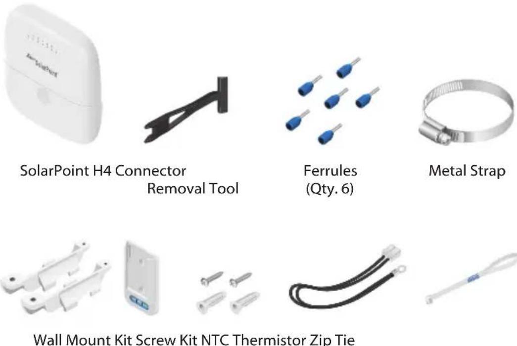
Installation Requirements
- Flathead screwdriver
- 7 mm socket wrench
• Ferrule crimper or pliers
• 18 - 14 AWG wires for battery connection
• 24V or 2x 12V SLA, AGM, or Gel Lead battery
• Solar panel with H4 connectors (10 - 60V open circuit voltage) - Shielded Category 5 (or above) cabling should be used for all wired Ethernet connections
• We recommend that you protect your networks from harmful outdoor environments and destructive ESD events with industrial-grade, shielded Ethernet cable from Ubiquiti. For more details, visit: ui.com/toughcable
Hardware Overview

| Interface | Description |
| System LED | Steady on when system is powered on; Red when battery polarity is reversed. |
| Reset Button | Press and hold the Reset button for 10 seconds to restore factory default settings. Press and hold the Reset button for 16 seconds if: The device does not respond to a factory reset. The web interface is unreachable. There doesn't appear to be any other noticeable activity |
| Battery Terminal | Four-pin terminal block for NTC and battery |
| Power Terminal | Two-pin terminal block for power (24VDC out) |
| PV Panel Terminals | H4 connectors for solar panel |
| Ethernet Ports | Supports 10/100 Ethernet connections and passive 24V, 2-pair PoE output. |
| Output LED | Steady on when output power is enabled. |
Hardware Installation

Note: Prior to use, it is recommended to write down the factory default password for this device. The password can be found on the sticker located under the SolarPoint cover.
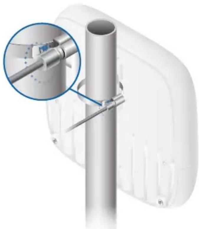
Pole Mounting
- Open the Metal Strap and feed it through the mounting slots on the back of the SolarPoint.

- Wrap the Metal Strap around the pole. Use a 7 mm socket wrench to turn the screw clockwise and securely fasten the strap to the pole.
Wall Mounting
- Attach the two wall mount brackets to the back of the SolarPoint.

- Install the wall mount level securely to the wall.

- Align the wall mount brackets over the wall mount level and slide it down until it is secure.

Opening the Port Cover
- Press down and slide the port cover forward.
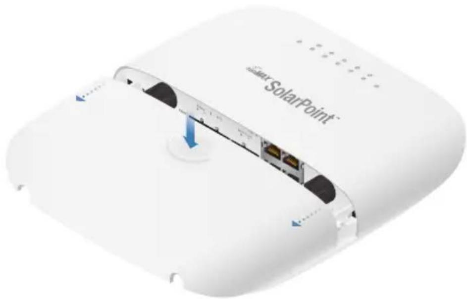
- Lift the port cover up.
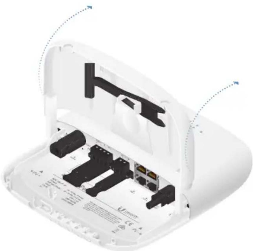
- Remove the four-pin connector from the battery terminal block.
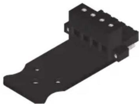
- Crimp a ferrule on one end of the wire.

- Insert the crimped wire into the appropriate slot on the four-pin connector. Using a flathead screwdriver, secure the wire to the connector by tightening the screw until it stops.

- Repeat steps four and five until the connector is fully occupied with all four wires.
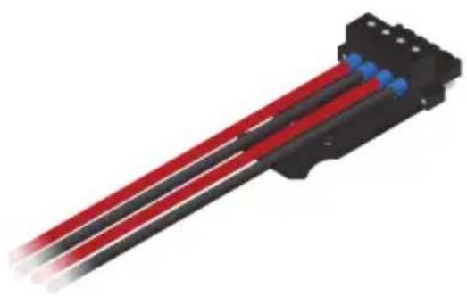
- Attach the NTC and battery cable using the four-pin connector.

- Attach the PV panel cables.
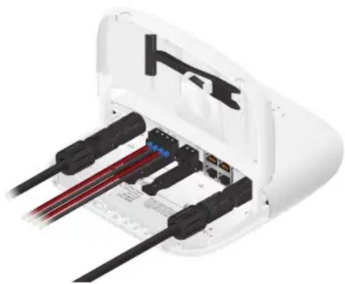
Connecting Ethernet
- Connect Ethernet cable(s) to the Ethernet port(s).

Note: PoE is disabled by default and can be enabled using the configuration interface.
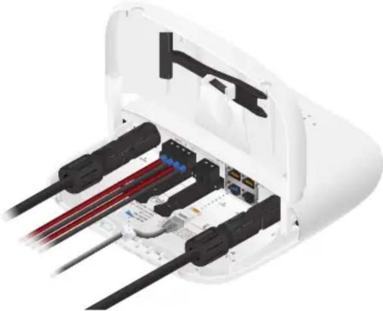
- When you are finished, close the port cover.

Configuration
Connect to your LAN via Ethernet or Wi-Fi.
Ethernet
If connected to the LAN via Ethernet, the SolarPoint will attempt to obtain an IP address automatically from a DHCP server. Use the Ubiquiti Device Discovery Tool to determine its IP address.
If there is no DHCP server on the LAN, the SolarPoint will fall back to the following IP address: 192.168.1.20
Wi-Fi
Connect your notebook, tablet, or smartphone to the SolarPoint SSID named SolarPoint-XYZ, where XYZ represents the last three characters in the MAC address of the SolarPoint.
Once connected to your wireless network, the SolarPoint will use the following IP address: 192.168.153.1
User Interface
- Launch a web browser and enter the IP address of the SolarPoint. Press Enter (PC) or Return (Mac).
- Enter ubnt in the Username field.
- Enter the password in the Password field (the password can be found on the sticker located under the port cover.)
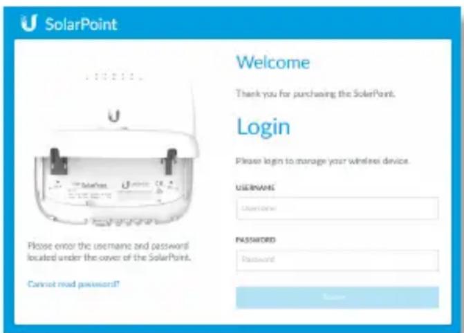
- Click Set Device Location to set the location for your solar system installation.

- Click Power on the Settings screen and fill out the battery and solar panel information.

Enabling PoE
To enable PoE on the SolarPoint:
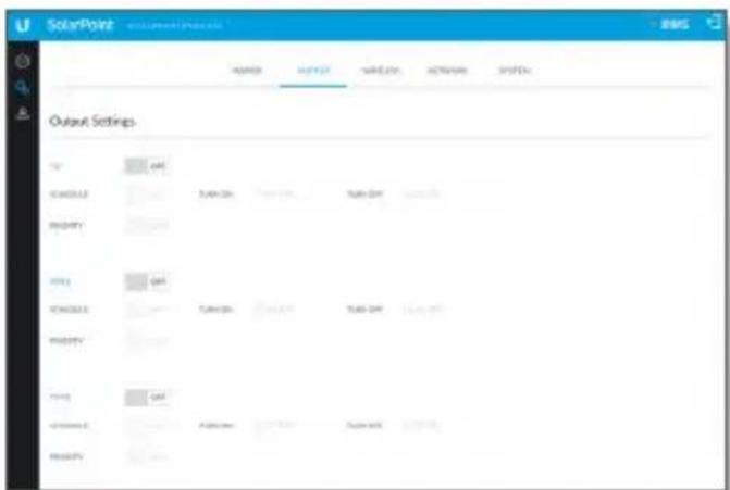
- Click Output on the Settings screen.
- Click the toggle button from OFF to ON, for each port you want to enable.
Specifications
| SM-SP-40 | |
| Dimensions 202 x 186 x 50 | mm (7.95 x 7.32 x 1.97") |
| Weight 650 g (1.43 lb) | |
| Enclosure Characteristics UV-Resistant Polycarbonate, Outdoor Use | |
| Max. Power Consumption 2W | |
| Networking Interface (4) 10/100 Fast Ethernet Ports | |
| Management Interface Ethernet | Wi-Fi (2.4 GHz) |
| Button Reset | |
| LEDs System, Output | |
| Power Source PV Panel (H4 Connectors) | |
| PV Input Voltage Range 10 - 60V(Reverse Protection, Surge Protection) | |
| PV Maximum Current 10A | |
| PV Power Control MPPT | |
| Output Interfaces 24VDC Passive PoE (Pins 4, 5+; 7, 8-)24VDC Terminal Block | |
| Output Voltage Battery Voltage Limited to 24V(Surge Protection) | |
| Maximum Power Output | PoE: 17WDC Out: 24WTotal: 40W Max. |
| Battery Type | 24V SLA, AGM, Gel lead battery |
| Boost Voltage Steps | 27.4V, 28.2V, 29.1V, 30V |
| Float Charge Voltage | 95% of Boost Voltage |
| Max. Charge Current | 7A |
| Under Voltage Protection | 22 – 23.6V Software Configurable22V Hardware ProtectionTwo Priority Levels for Output Disable |
| Operating Temperature | -20 to 50°C (-4 to 122°F) |
| Operating Humidity | IPx4 |
| Certifications | FCC, IC, CE |
Safety Notices
- Read, follow, and keep these instructions.
- Heed all warnings.
- Only use attachments/accessories specified by the manufacturer.

WARNING: Do not use this product in location that can be submerged by water.

WARNING: Avoid using this product during an electrical storm. There may be a remote risk of electric shock from lightning.
Electrical Safety Information
- Compliance is required with respect to voltage, frequency, and current requirements indicated on the manufacturer's label. Connection to a different power source than those specified may result in improper operation, damage to the equipment or pose a fire hazard if the limitations are not followed.
- There are no operator serviceable parts inside this equipment. Service should be provided only by a qualified service technician.
- The equipment requires the use of the ground wire as a part of the safety certification, modification or misuse can provide a shock hazard that can result in serious injury or death.
Limited Warranty
ui.com/support/warranty
The limited warranty requires the use of arbitration to resolve disputes on an individual basis, and, where applicable, specify arbitration instead of jury trials or class actions.
Compliance FCC
Changes or modifications not expressly approved by the party responsible for compliance could void the user's authority to operate the equipment.
This device complies with Part 15 of the FCC Rules. Operation is subject to the following two conditions:
- This device may not cause harmful interference, and
- This device must accept any interference received, including interference that may cause undesired operation.
This equipment has been tested and complies with the limits for a Class A digital device, pursuant to Part 15 of the FCC Rules. These limits are designed to provide reasonable protection against harmful interference when the equipment is operated in a commercial environment. This equipment generates, uses, and can radiate radio frequency energy and, if not installed and used in accordance with the instruction manual, may cause harmful interference to radio communications. Operations of this equipment in a residential area is likely to cause harmful interference in which case the user will be required to correct the interference at his own expense.
This radio transmitter (FCC ID: SWX-SMSPW) has been approved by FCC.
ISED Canada
CAN ICES-3(A)/NMB-3(A)
This device complies with ISED Canada licence-exempt RSS standard(s). Operation is subject to the following two conditions:
- This device may not cause interference, and
- This device must accept any interference, including interference that may cause undesired operation of the device.
This radio transmitter (IC: 6545A-SMSPW) has been approved by ISED Canada.
CAN ICES-3(A)/NMB-3(A)
Radiation Exposure Statement:
- This equipment complies with radiation exposure limits set forth for an uncontrolled environment.
- This equipment should be installed and operated with minimum distance 20 cm between the radiator and your body.
- This transmitter must not be co-located or operating in conjunction with any other antenna or transmitter.
AVIS IMPORTANT :
Australia and New Zealand

Warning: This equipment is compliant with Class A of CISPR 32. In a residential environment this equipment may cause radio interference.
CE Marking
CE marking on this product represents the product is in compliance with all directives that are applicable to it.

RoHS/WEEE Compliance Statement

English
European Directive 2012/19/EU requires that the equipment bearing this symbol on the product and/or its packaging must not be disposed of with unsorted municipal waste. The symbol indicates that this product should be disposed of separately from regular household waste streams. It is your responsibility to dispose of this and other electric and electronic equipment via designated collection facilities appointed by the government or local authorities. Correct disposal and recycling will help prevent potential negative consequences to the environment and human health. For more detailed information about the disposal of your old equipment, please contact your local authorities, waste disposal service, or the shop where you purchased the product.
Deutsch
Declaration of Conformity
English Hereby, UBIQUITI, declares that this SM-SP-40 device, is in compliance with the essential requirements and other relevant provisions of Directives 2014/53/EU, 2014/30/EU, 2014/35/EU. The full text of the EU declaration of conformity is available at the following internet address: ui.com/compliance
685 Third Avenue, 27th Floor
New York, NY 10017
USA
Support help.ui.com
Community community.ui.com
Downloads downloads.ui.com
- INTRODUCTION
- PACKAGE CONTENTS
- INSTALLATION REQUIREMENTS
- HARDWARE OVERVIEW
- HARDWARE INSTALLATION
- POLE MOUNTING
- WALL MOUNTING
- OPENING THE PORT COVER
- CONNECTING ETHERNET
- CONFIGURATION
- ETHERNET
- WI-FI
- USER INTERFACE
- ENABLING POE
- SAFETY NOTICES
- ELECTRICAL SAFETY INFORMATION
- LIMITED WARRANTY
- COMPLIANCE FCC
- ISED CANADA
- CAN ICES-3(A)/NMB-3(A)
- RADIATION EXPOSURE STATEMENT
- AVIS IMPORTANT
- AUSTRALIA AND NEW ZEALAND
- CE MARKING
- ROHS/WEEE COMPLIANCE STATEMENT
- ENGLISH
- DEUTSCH
- DECLARATION OF CONFORMITY
Brand : Ubiquiti Networks
Model : SunMAX SM-SP-40
Category : Phone Charger