
PT-JOY-G4 - Regulator PTZ Optics - Free user manual and instructions
Find the device manual for free PT-JOY-G4 PTZ Optics in PDF.


| Product Type | Joystick Camera Controller |
| Model | PT-JOY-G4 |
| Brand | PTZ Optics |
| Control Interfaces | Network (RJ-45, PoE), RS-232, RS-485, RS-422 |
| Supported Protocols | PTZOptics VISCA, VISCA over IP, PELCO-D, PELCO-P, limited Sony VISCA |
| Maximum Cameras | 255 via network, 7 via serial VISCA |
| Power Supply | 12V DC, 6W, or PoE 802.3af |
| Dimensions (W x D x H) | 11.938 x 9.25 x 2.188 in (303.23 x 234.95 x 55.58 mm); 4.25 in (107.95 mm) incl. joystick |
| Weight | 4.45 lbs (2.02 kg) |
| Operating Temperature | 14°F to 122°F (-10°C to 50°C) |
| Operating Humidity | 10% to 90% (non-condensing) |
| Variable Baud Rate | 1200 to 19200 bps |
| Warranty | 2 Year Manufacturer Warranty |
| Included Accessories | 12V 2A power supply, RS-232C cable (DB9 female to 8-pin mini-din), Quick Start Guide, Grounding Pin |
| Key Features | Variable speed pan/tilt/zoom, exposure & white balance control, preset management (0-255), OSD menu, web interface, matrix mode, basic mode, backlight compensation, focus lock |
Frequently Asked Questions - PT-JOY-G4 PTZ Optics
User questions about PT-JOY-G4 PTZ Optics
0 question about this device. Answer the ones you know or ask your own.
Ask a new question about this device
Download the instructions for your Regulator in PDF format for free! Find your manual PT-JOY-G4 - PTZ Optics and take your electronic device back in hand. On this page are published all the documents necessary for the use of your device. PT-JOY-G4 by PTZ Optics.
USER MANUAL PT-JOY-G4 PTZ Optics
A 4th-Generation Network or Serial Camera Controller
PT-JOY-G4

User Guide
V1.1
Please check ptzoptics.com for the most up to date version of this document
Thank You!
Thank you for selecting our joystick camera controller built to support either IP or serial communication. As you read through this manual it will help identify the options you have for setting up the device, connecting equipment as well as recommended configurations; as a result we recommend reading over this guide prior to beginning any setup to have the best possible experience.
-The PTZOptics team
Using this guide to Get Started
We recommend that you read the entire user guide prior to any setup and please refer to the Table of Contents when attempting to locate specific product information or setup instructions.
Copyright Notice
The entire contents of this manual / guide, whose copyright belongs to PTZOptics, may not be cloned, copied, or translated in any way without the explicit permission of the company. The product specifications referred to in this document are for reference only and as such are subject to updating at any time without prior notice.
What's in the Box?
• PT-JOY-G4 joystick controller
• 12V 2A international power supply
- 8' (2.4m) RS-232C / DB9 female to 8-pin mini-din male cable
- PTZOptics PT-JOY-G4 Quick Start Guide
- Grounding Pin
Introducing the PT-JOY-G4
The PT-JOY-G4 is designed to provide in depth control of the PTZOptics and HuddleCamHD line of cameras for use in production environments and more. With the ability to support either IP or Serial control from a single controller, the PT-JOY-G4 presents itself as a flexible control solution.
When used via a Local Area Network (LAN), you can connect to cameras using TCP or UDP communications to send PTZOptics VISCA over IP commands, with limited support for Sony VISCA over IP capable cameras. If using the serial connections via RS-232, RS-485 or RS-422 you have PTZOptics VISCA commands, Pelco-D, Pelco-P and limited Sony VISCA support.
Note using this with non PTZOptics or HuddleCamHD products may offer limited or no control capabilities.

You can view the PTZOptics VISCA and VISCA over IP command libraries at ptzoptics.com/downloads/
How to care for your PT-JOY-G4
Please read the recommendations below to ensure you do not damage the product or possibly void your warranty.
- Keep the joystick away from rain and out of moist environments
- Do not remove any portions of the case, cover or interfaces
- Removal may result in the risk of an electrical shock
- Removal will void the manufacturer's warranty.
- Only use the product within the recommended temperature and humidity ranges
○ Operating temperature range: 14irc 122ircF ( -10irc +50ircC )
○ Operating humidity range: 10 \~ 90% *Non-condensing
- Do not use any other power supply than the one originally supplied with the joystick.
- Keep the joystick and signal cables away from strong electromagnetic sources or abnormal and unreliable control may be experienced
- If you need to clean the surface of the product please use a soft dry cloth.
- If the joystick becomes extremely dirty, use a diluted neutral detergent to clean the surface.
- Do not use any type of solvents, which may damage the surface of the product.

In case of abnormal operation, please contact PTZOptics support at support@ptzoptics.com
Table of Contents
| Preface | 2 |
| Copyright Notice | 2 |
| What's in the Box | 3 |
| Introducing the PT-JOY-G4 | 3 |
| How to care for your PT-JOY-G4 | 3 |
| Table of Contents | 4 |
| PT-JOY-G4 Overview | 5 |
| Top Down View & Layout | 5 |
| Button & Dial Descriptions | 6 |
| Rear Panel View & Layout | 8 |
| Technical Specifications | 9 |
| Preparing to use the Joystick | 10 |
| Installation and Setup | 10 |
| Power | 10 |
| Grounding Pin | 10 |
| Physically Connecting a Camera to the Controller | 10 |
| Network Setup | 11 |
| Serial Control Setup & Options | 11 |
| Adding a Camera | 13 |
| From the Joystick | 13 |
| From the Web Interface | 14 |
| Joystick OSD Menu Control | 15 |
| Operating the Camera | 16 |
| Pan, Tilt, & Zoom Operations | 16 |
| Setting and Calling Presets | 16 |
| Adjusting the Camera's Image | 17 |
| Camera OSD Menu Control | 18 |
| Basic Mode | 18 |
| Matrix Mode | 18 |
| Joystick Web Interface | 19 |
| Device Management | 19 |
| Control | 19 |
| Matrix Mode | 19 |
| Settings | 20 |
| Troubleshooting and Extras | 21 |
| Troubleshooting | 21 |
| Additional Information | 22 |
| Warranty | 22 |
| Certifications | 22 |
| Changelog | 22 |
PT-JOY-G4 Overview
Top Down View & Layout
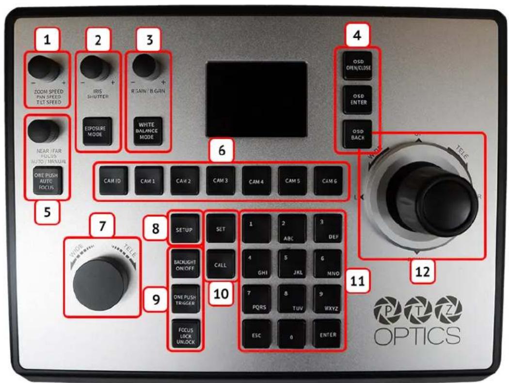
- Speed Control
- Exposure Control
- White Balance Control
- Camera OSD Control
- Focus Control
-
Camera Select
-
Zoom Control
- Controller OSD Setup button
- Fine Tune Video Control
- Preset Control Buttons
- Alpha-Numeric Keypad
- Joystick Controller
Button & Dial Descriptions
The below descriptions will describe the buttons and dials available on the controller.
1. Speed Control
The Speed Control section allows you to adjust the speed at which you pan, tilt, and zoom the camera.
a. [SPEED] Knob
Twist the Speed Control knob to increase or decrease the set control speed.
Press the Speed Control knob in to cycle through zoom, pan, and tilt speeds options.
Zoom Speed Range: 1 - 7
Pan Speed Range: 1 - 24
Tilt Speed Range: 1 - 20
2. Exposure Control
The Exposure Control section allows you to adjust the exposure settings of the camera.
a. [IRIS / SHUTTER] Knob
Twist the [IRIS / SHUTTER] knob to adjust the Iris / Shutter value.
Press the [IRIS / SHUTTER] knob to toggle between Iris and Shutter adjustments.
b. [EXPOSURE MODE] Button
Press the [EXPOSURE MODE] button to cycle through Exposure modes.
Options include: Auto, Manual, Shutter Priority, Iris Priority, & Brightness Priority.
3. White Balance Control
The White Balance Control section allows you to adjust the white balance settings of the camera.
a. [R GAIN / B GAIN] Dial
Twist the [R GAIN / B GAIN] knob to adjust the Red Gain / Blue Gain value.
Press the [R GAIN / B GAIN] knob to toggle red gain and blue gain adjustment control.
b. [WHITE BALANCE MODE] Button
Press the [WHITE BALANCE MODE] button to cycle through the White Balance Modes.
Options include: Auto, Indoor, Outdoor, One Push, & Manual.
4. Camera OSD Control
The Camera OSD Control section allows you to open and adjust the camera's on screen display menu.
a. [OSD OPEN / CLOSE] Button
Press the [OSD OPEN / CLOSE] button to open and close the on screen display menu.
Move the joystick up, down, left, and right to traverse the camera's OSD menu.
b. [OSD ENTER] Button
Press the [OSD ENTER] button to select an OSD menu option.
c. [OSD BACK] Button
Press the [OSD BACK] button to go back an OSD menu option.
Refer to the Camera OSD Menu Control section of this guide for more information.
5. Focus Control
The Focus Control section allows you to adjust the focus value of the camera.
a. [NEAR / FAR FOCUS] Dial
Twist the [NEAR / FAR FOCUS] dial to focus the camera's image on your scene.
Press the [NEAR / FAR FOCUS] dial in to toggle Auto Focus and Manual focus modes.
b. [ONE PUSH AUTO FOCUS] Button
Press the [ONE PUSH AUTO FOCUS] button to automatically focus the image on the scene while staying in Manual Focus mode.
6. Camera Select
The Camera Select section allows you to select a camera to control.
a. [CAM ID] Button
The [CAM ID] button allows you to select any camera on the controller using the alpha-numeric keypad.
b. [CAM #] Button
The [CAM #] button allows you to quickly select a camera to control.
Options include: 1 - 6
7. Zoom Control
The Zoom Control sections allow you to zoom the camera in and out of the scene.
a. [FINE TUNE ZOOM] Knob
The [FINE TUNE ZOOM] knob allows you to finely zoom the camera in and out at the lowest speed (1) setting.
8. Controller OSD Setup
The Controller OSD Setup allows you to adjust the settings of the controller.
a. [SETUP] Button
Press the [SETUP] button to open the joystick's OSD menu.
Refer to the Joystick OSD Menu Control section of this guide for more information.
9. Fine Tune Video
The Fine Tune Video section allows you to quickly change the camera's video settings.
a. [BACKLIGHT ON / OFF] Button
Press the [BACKLIGHT ON / OFF] button to toggle the camera's backlight compensation mode.
b. [ONE PUSH TRIGGER] Button
Press the [ONE PUSH TRIGGER] button to trigger the camera to calculate the scene's white balance value.
c. [FOCUS LOCK / UNLOCK] Button
Press the [FOCUS LOCK / UNLOCK] button to lock or unlock the camera's focus value from the current position.
10. Preset Control
The Preset Control section allows you to set and call presets of the cameras.
a. [SET] Button
Press the [SET] button to set a camera preset. Use the alpha-numeric keypad to set a preset number.
b. [Call] Button
Press the [CALL] button to call a camera preset. Use the alpha-numeric keypad to call a preset number.
c. Quick set preset shortcut
Press and hold a number on the alpha-numeric keypad for 3+ seconds to set a camera preset in the current location for that preset number.
d. Quick call preset shortcut

Quickly press a number on the alpha-numeric keypad to call a camera preset.
Refer to the Setting and Recalling Presets section of this guide for more information.
11. Alpha-numeric Keypad
The alpha-numeric keypad allows you to use many of the controller features that require numbers and letters, such as adding a camera from the controller OSD.
12. Joystick Controller
The joystick controller allows you to pan, tilt, and zoom (twist) the camera. The control speed is affected by the Speed Control dial settings.
Rear Panel View & Layout
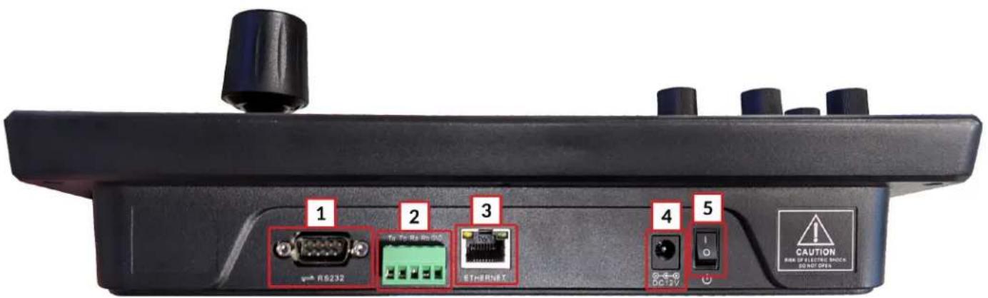
- RS-232 Control Connection
- RS-422 / RS-485 Control Connection

Refer to the Physically Connecting a Camera to the Controller section of this guide for more information.
- Ethernet / RJ-45 (PoE) Network Connection Supports 802.3af PoE power
- 12VDC Power Connection
- Power Switch (Only for 12V DC connections)
Technical Specifications
| Control Interfaces | Network: NIC (TCP and UDP) Serial: RS-232 Full Duplex, RS-485 Semi Duplex, RS-422 Full Duplex |
| Protocols | PTZOptics VISCA and VISCA over IP PELCO-D and PELCO-P via Serial Ports Limited Sony VISCA and VISCA over IP support |
| Variable Baud Rate | 1200 to 19200 bps |
| Recommended Maximum Cable Distance* | Ethernet: 328 feet | 100 Meters RS-232: 50 feet | 15 Meters RS-485: 3,937 feet | 1200 Meters RS-422: 50 feet | 15 Meters |
| Maximum Cameras | 255 cameras via network | 7 cameras via serial VISCA |
| Power Voltage | 12V DC |
| Power Consumption | 6W |
| Power over Ethernet | 802.3af |
| Working Temperature | 14°F ~ 122°F (-10°C ~ +50°C) |
| Working Humidity | 10% ~ 90% (non condensation) |
| Weight | 4.45 lbs | 2.02 kg |
| Dimensions | 11.938 W x 9.25 D x 2.188 H (4.25 H incl. joystick) in 303.23 W x 234.95 D x 55.58 H (107.95 H incl. joystick) mm |
| Shipping Weight | 5.80 lbs | 2.63 kg |
| Box Dimensions | 14 W x 8.75 D x 5.5 H in 355.6 W x 222.25 D x 139.7 H mm |
| Warranty | 2 Year Manufacturer Warranty |
*Using high quality certified cabling
Preparing to use the Joystick
Installation & Setup
Power
You can power your joystick using the included power supply or Power over Ethernet (802.3af). After applying power make sure that the I/O switch is flipped to "I" for "On".

Do not power the joystick controller using PoE and the power supply at the same time.
Grounding Pin
Before installing the grounding pin, you should first locate a grounded source such as a wall outlet. Once located, connect one end of the grounding pin to the SuperJoy's chassis, and to the other end to the grounded source.
Physically Connecting a Camera to the Controller
To connect to a camera, you first need to decide which supported control method you need
Network Control: To control your camera(s) over a network, connect an ethernet cable from your Local Area Network (LAN) to the controller and another one to the camera. Afterwards, add the camera's IP address to the joystick's list of cameras and designate a control address.
Serial RS-232 Control: To control your camera(s) over a serial connection, use the included RS-232C cable to connect the joystick and the camera. Then, designate a control address for the camera.

Serial RS-485 Control: To control your camera(s) over an RS-485 connection, see below.
- Joystick Ta - Pin 1 - Camera (+)
- Joystick Tb - Pin 2 - Camera (-)
- Joystick GND - Pin 5 - Camera (G) (Some cameras won't require ground)
Serial RS-422 Control: To control your camera(s) over an RS-422 connection, see below.
- Joystick Ta - Pin 1 - Camera (Rx-)
- Joystick Tb - Pin 2 - Camera (Rx+)
- Joystick Ra - Pin 3 - Camera (Tx-)
- Joystick Rb - Pin 4 - Camera (Tx+)
- Joystick GND - Pin 5 - Camera (G) (Some cameras won't require ground)

For a more in-depth guide to adding cameras to the joystick, check out the Adding a Camera section
Network Setup
The PT-JOY-G4 will dynamically obtain an IP address upon connection to your LAN. If your network is not able to supply DHCP addresses you must assign a static IP address to the controller.
To set a static IP address, follow the steps below.
- Obtain the IP address scheme of your network.
- Connect your joystick to power and to your network.
- Turn on your joystick controller.
- Press the [SETUP] button, and move down to option 4. Network Connection.
- Move the joystick left or right to "Static", and press the [ENTER] key to set the static IP address.
- Enter an available IP address similar to the IP address scheme of your network using the alpha-numeric keypad.
- Enter the Gateway and Subnet Mask of your network.
- When all the fields are filled, press the [ENTER] key to restart the joystick with the assigned static IP address.

For more information on methods to obtain your network information such as the IP address, Default Gateway, and Subnet Mask refer to the following PTZOptics Knowledge Base Article.

Note that If any aspect of your network scheme only requires 1 or 2 digits (e.g. 192.168.1.150), you can move the joystick right to advance to the next field.
Serial Control Setup & Options
To control cameras using serial communications, first review the above section marked "Physically Connecting a Camera" to select the appropriate option for your setup.
Once you have selected a serial communications method, connect the appropriate cable to the joysticks selected control port, and then to the camera's matching control input (RS-485 or RS-232).
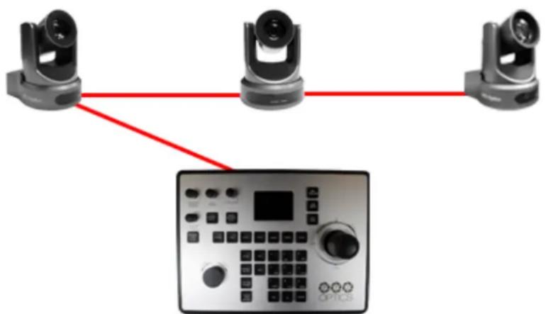
When controlling multiple cameras, you have two (2) methods of connection. The two (2) methods consist of "Daisy Chaining" and a "Home-Run" setup.
Daisy-Chain
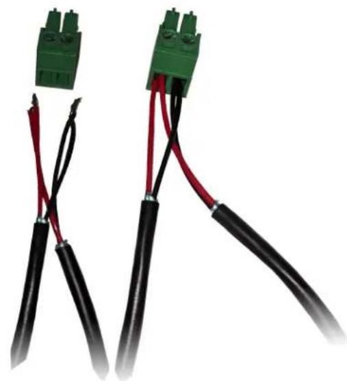
To utilize a Daisy-Chaining setup, you will first connect the joystick to camera 1, then connect camera 1 to camera 2, etc. Daisy-Chaining can be used with both RS-232 & RS-485. Please use the figures below for reference.
natural_image
Three connected devices: three with camera heads and one with a control panel labeled OPTICS (no text or symbols on devices)Daisy-Chain Connection Guide

RS-232 Daisy-Chain connection
natural_image
Two black and red electrical connector wires with green connectors (no text or symbols visible)RS-485 Daisy-Chain connection
Home-Run
To utilize a Home-Run setup, you will need to connect all the cameras to the controllers' 5 port phoenix connector. Home-Run setups can be used with both RS-485 & RS-422. Please use the figures below for reference.

natural_image
Three identical camera modules connected to a central control panel labeled 'OPTICS', with red lines radiating from each component (no text or symbols on the devices themselves)Home-Run Connection Guide

natural_image
Two green electrical connectors with black and red wires, shown from different angles (no text or symbols visible)RS-485 Home-Run connection

When you first boot up the joystick it will be in the IP mode.
To toggle between IP and Serial control, press and hold the joystick button for 3+ seconds.
Adding a Camera
From the Joystick
To add a camera to the joystick from the OSD setup menu, follow the steps below.
- Adding an IP camera
a. Press the [SETUP] button, and select option one (1) "Add Network Device" for IP
b. Fill out the Network Device fields to connect your camera.
Camera: Joystick Camera Address [CAM ID]. Options include 1 - 255.
Protocol: Options include VISCA (UDP), VISCA (TCP), and Sony VISCA (UDP).
IP Add.: IP Address of Camera to Control
Port: Camera control port.
c. Once the above fields are filled, press the [ENTER] button to save the camera to the controller.

For PTZOptics and HuddleCamHD cameras, by default, the port assignments are 1259 for UDP control and port 5678 for TCP control.
- Adding a Serial camera
a. Press the [SETUP] button, and select option two (2) "Add Serial Device" for serial.
b. Fill out the Serial Device fields to connect your camera.
Camera: Joystick Camera Address. Options include: 1 - 7.
Protocol: Control protocol. Options include: VISCA, PELCO-D, & PELCO-P
Address: Camera control address. For best results, set Joystick & Camera control address to the same value.
Baud Rate: Baud rate. Options include: 1200, 2400, 4800, 9600, 19200, 38400, & 115200. For best results, use 9600.
c. Once the above fields are filled, press the [ENTER] button to save the camera to the controller.
From the Web Interface
To add a camera to the controller from the web interface, follow the steps below.
- Type the IP address displayed on the controllers OSD into a web browser to access the web interface.
- Type in the login credentials to access the joysticks WebUI configuration page.
a. Default username: "admin"
b. Default password: (there is no password by default)
- Click the pencil icon under the "Operate" column of the camera address you wish to configure a camera for.

- From here, fill out the information based on the deployed connection to the camera, with your options detailed below.
- Network:
- Protocol: Options include: VISCA (UDP), VISCA (TCP), & SONY VISCA (UDP)
- IP: Enter the IP address of your camera
- Port: Enter the control port of your camera
- Serial:
- Protocol: Options include: VISCA, PELCO-D, & PELCO-P
○ Baud Rate: Options include: 1200, 2400, 4800, 9600, 19200, 38400, & 115200 -
Address: (Unchangeable) This address matches the camera address at the top of the window.
-
Once the above fields are filled, click the Save button to finish adding the camera to the controller.

Joystick OSD Menu Control
1. Add Network Device

Refer to the Adding a Camera section of this guide for more information.
2. Add Serial Device

Refer to the Adding a Camera section of this guide for more information.
3. Device List
- Move the joystick left or right to select Inquire or Delete.
From here, you can view current configurations or delete any camera from the Device List. - Move the joystick up or down to traverse the menu by increments of 1.
Move the joystick left or right to traverse the menu by increments of 5.
4. Network Connection

Refer to the Network Setup section of this guide for more information.
5. Language
- Move the joystick left or right to adjust the language.
Options include: English
6. Button Tone
- Move the joystick left or right to select On or Off.
- After making a selection, press the [ENTER] button to apply.
7. Restore Factory
- Press the [ENTER] button to restore the joystick to factory default settings.
- You will be prompted to confirm, press the [ENTER] key again to restore to factory default, or press the [ESC] button to cancel.

Restoring the joystick to factory default settings will remove all cameras, set all control speeds back to default, and reset network information.
8. System Info
- Press the [ENTER] button to view the controller's system information. Includes: Software Version, Hardware Version, Web Version, IP Address, Gateway, & Subnet Mask.
Operating the Camera
To begin remotely operating a camera, you will first need to use the Camera Select buttons to begin using the controller. Once selected, you will have full remote operation of the selected camera from the controller.
Pan, Tilt, and Zoom Operation
The controller supports variable speed pan / tilt / zoom control, which allows you to set the control speeds prior to use.
You can adjust the control speed using the Speed Knob located on the top left corner of the joystick. Once the control speeds are set to a comfortable value, you can use the joystick controller to move the camera.
In addition to the joystick itself, you can use the Fine Tune Zoom Dial to zoom in and out at the slowest possible speed.
Setting and Recalling Presets
Using the Quick Presets you can set and call presets 0 - 9 using the Alpha-Numeric keypad by following the steps below.
Quick Presets:
- Move the camera to the P/T/Z location you wish to set the preset.
- Press and hold one of the Alpha-Numeric buttons for 3+ seconds to set the corresponding preset.

The controller OSD will notify you upon successfully storing a quick preset.
- To call a Quick Preset, press one of the Alpha-Numeric buttons.
Alternatively, you can use the Set and Call buttons to set or call presets 0 - 255.
Set and Call:
- Move the camera to the P/T/Z location you wish to set the preset.
- Press the [SET] button.
- Using the Alpha-Numeric keypad, type in a preset number to associate with the preset. Press [ENTER] to save the preset.
- To call a preset, press the [CALL] button, and type in a preset number. Press the [ENTER] key to call the preset.

When using a PTZOptics camera, you can call a preset at a specific focus value by setting the preset while in manual focus mode.
Adjusting the Camera's Image
There are many options for adjusting the camera's image which we will detail below
You can adjust Exposure & White Balance settings, Iris, Shutter, Red & Blue Gain, Focus, & Backlight Compensation to achieve the desired image style and quality.
- Exposure Control: Use the [EXPOSURE MODE] button to cycle through the camera's Exposure modes. Options include: Manual Exposure, Shutter Priority, Iris Priority, Brightness Priority, & Auto Exposure respectively.
You can use the [IRIS / SHUTTER] Knob to adjust the Iris and Shutter values. Press in the dial to toggle between Iris and Shutter.

The camera will automatically change to Manual Exposure upon twisting the Iris / Shutter Knob.
- White Balance Control: Use the [WHITE BALANCE MODE] button to cycle through the camera's White Balance modes. Options include: Indoor White Balance, Outdoor White Balance, One Push White Balance, Manual White Balance, & Auto White Balance respectively.
You can use the [R GAIN / B GAIN] Knob to adjust the Red & Blue Gain values.
Press the knob to toggle between Red Gain and Blue Gain. For adjustment when in supporting White Balance Modes.

The camera will automatically change to Manual White Balance upon twisting the R Gain / B Gain Knob.
When the camera is in One Push White Balance, you can press the [ONE PUSH TRIGGER] button from the Fine Tune Video control section of the joystick to calibrate the white balance.
- Focus Control: Twist the [FOCUS] Knob towards Near or Far to focus the camera on a subject. You can press down on the [FOCUS] Knob to toggle between AutoFocus and Manual Focus Modes.
The [ONE PUSH AUTO FOCUS] button allows you to automatically focus the image on the scene, without exiting the Manual Focus mode, but will not override the Focus Lock.

PTZOptics cameras will return to Auto Focus mode upon zooming in or out. You can lock the camera's focus from returning to Auto Focus mode by pressing the [FOCUS LOCK / UNLOCK] button. While the focus is locked, you have full manual focus control from the [FOCUS] Knob. Press the [FOCUS LOCK / UNLOCK] button again to return to normal focus control.
- Backlight Compensation: Press the [BACKLIGHT ON/OFF] button to enable or disable Backlight Compensation.
Camera OSD Menu Control
To access the camera's On Screen Display, OSD, menu and fine tune the camera, follow the steps provided below.
- Press the [OSD OPEN/CLOSE] button.
- Move the joystick up or down to traverse the camera's OSD menu.
- Press the [OSD ENTER] button to select a specific option.
- Move the joystick left and right to adjust the settings.
- Press the [OSD BACK] button to return to the previous window.
- Press the [OSD OPEN/CLOSE] button again to close the camera's OSD menu.

PTZOptics cameras will automatically close their OSD Menu after 2 minutes 30 seconds of inactivity by default, unless adjusted on the camera's OSD Menu.
Matrix Mode
Matrix Mode allows you to disable most of the capabilities of the PT-JOY-G4 and limit the controls to calling presets 1 - 3 of cameras 1 - 3.
You can change modes by holding the "ESC" button for 3+ seconds. You will cycle from Normal Mode > Matrix Mode > Basic Mode > Normal Mode etc.
- Press 1 - 3 on the alpha-numeric keypad to call camera 1 presets 1 - 3 respectively.
- Press 4 - 6 on the alpha-numeric keypad to call camera 2 presets 1 - 3 respectively.
- Press 7 - 9 on the alpha-numeric keypad to call camera 3 presets 1 - 3 respectively.
Basic Mode
Basic Mode allows you to disable most of the capabilities of the PT-JOY-G4 and limit the control to the joystick and/or calling presets.
You can change modes by holding the "ESC" button for 3+ seconds. You will cycle from Normal Mode > Matrix Mode > Basic Mode > Normal Mode etc.
- Press the [BASIC MODE] button to enable Basic Mode with Joystick.
- Press the [BASIC MODE] button again to enable Basic Mode without Joystick.
- Press the [BASIC MODE] button again to disable Basic Mode.
Joystick Web Interface
Device Management
The Device Management page, available from the controllers web interface, allows you to define new cameras and adjust already configured cameras.
| Camera | IP | Port | Protocol(network) | Baudrate | Address | Protocol(analog) | Operate | |
| 1 | 192.168.108.46 | 1259 | VISCA(UDP) | 9600 | 1 | VISCA | ||
| 2 | 192.168.100.88 | 1259 | VISCA(UDP) | 9600 | 2 | VISCA | ||
| 3 | 192.168.100.88 | 1259 | VISCA(UDP) | 9600 | 3 | VISCA | ||
| 4 | 192.168.100.88 | 1259 | VISCA(UDP) | 9600 | 4 | VISCA | ||
| 5 | 192.168.100.88 | 1259 | VISCA(UDP) | 9600 | 5 | VISCA | ||
| 6 | 192.168.100.88 | 1259 | VISCA(UDP) | 9600 | 6 | VISCA | ||
| 7 | 192.168.100.88 | 1259 | VISCA(UDP) | 9600 | 7 | VISCA |
Camera: Joystick control address.
Base options include: 1 - 7 (IP & Serial)
Expanded options include 1 - 255 (IP only)
IP: The IP address of the saved network camera.
Port: The network control port of the saved network camera.
Protocol (Network): The control protocol of the saved network camera.
Baud Rate: The baud rate of the saved serial camera.
Address: The camera control address of the saved serial camera.
Protocol (Serial): The control protocol of the saved serial camera.
Operate: Click this pencil to edit the settings of the saved camera.

For more information on editing already configured cameras from the Device Management interface, check out the Adding a Camera > From the Web Interface section.
Control
The Control page, available from the controllers web interface, allows you to call presets of the connected cameras. This page acts similarly to Basic Mode without Joystick.
Matrix Mode
The Matrix Mode page, available from the controllers web interface, allows you to call presets 1-3 of cameras 1-3. This page acts similarly to Matrix Mode.
Settings
The Settings interface allows you to adjust the configuration of the joystick.
Upgrade: Browse your PC and upgrade the joystick's firmware to the latest version.
Factory Restore: Restores the joystick to factory default settings.
Restart: Restart the joystick.
Import: Browse your PC and import joystick settings.
Export: Export joystick settings to PC.
System Settings: Invert Pan and/or Tilt.
Version: Displays the Hardware, Software, and Web firmware versions on the joystick.
Network: Allows configuration of the joystick's network configuration (DHCP / Static IP).
Options include: DHCP or Static (IP Address, Subnet Mask, Gateway, DNS1, & DNS2.)

For more information on how to obtain an IP address, Default Gateway, & Subnet Mask, see the following PTZOptics Knowledgebase Article: Discovering your Network IP Information
Troubleshooting and Additional Information
Troubleshooting
LCD Display shows "Control Failure"
This can occur when the controller doesn't receive a response from the camera.
- Please check that the network jacks you are using are active.
- Please check that the network cable you are using is not failing.
- Please check that the camera is supplying an Acknowledgement and Completion response.
The joystick isn't controlling any cameras at all
This can occur when the camera(s) and/or joystick aren't properly set up.
- Check that the network jacks you are using are active.
- Check that the network or serial cables you are using are not failing.
- Check that the camera control address matches the joystick control address.
- Check that you are in the correct control mode. Hold the Joystick Controller button for 3+ seconds to toggle between serial and Network control.
Multiple cameras are being controlled at once
This can occur when multiple cameras are set to the same joystick control address.
- Check the camera's control addresses and ensure that each camera has a unique address.
a. Open the joystick OSD menu and select option 3. Device List: Inquire. Check that none of the connected cameras have the same control address.
b. Log into the WebUI and select Devices. Check that none of the connected cameras have the same control address.
Camera doesn't stop moving when the joystick controller is upright
This can occur when the joystick is in OSD Menu control mode or when the network is congested.
- Move the joystick left and check that the LCD display says "Left". LCD display will say "CAM Menu Left" while in OSD Menu control mode.
a. Power cycle the joystick.
b. Press [OSD OPEN/CLOSE], then [OSD ENTER], then press [OSD OPEN/CLOSE] twice. - Move the joystick to an isolated network and test again. If the issue ceases, the original network is congested and/or overloaded.
- The joystick controller may have a power issue from your environment. To resolve this issue, install the grounding pin / wire to the base of the controller, and the other end to a grounded source.
Certain functions don't work with my camera
This can occur when you are not using a PTZOptics camera, or your camera's firmware isn't up to date.
-
Some functions do not work with non-PTZOptics cameras as each camera manufacturer has some of their own unique commands that may not be fully compatible with the design of this controller.
-
For PTZOptics cameras use the PTZOptics Firmware Finder to update your camera's firmware.

Check out the PTZOptics Firmware Finder to always have the latest features.
Check out the PTZOptics Knowledge Base and Forums for troubleshooting.
Contact the PTZOptics Support Team, Submit a Ticket if you need some extra assistance.
Additional Information
Warranty
The PT-JOY-G4 includes a 2 Year Limited Warranty. This warranty covers all manufacturers defects, and any damage that is done to the joystick during shipping. This warranty does not cover physical damage to the joystick that is due to lack of proper care. If you have trouble with your joystick and wish to see if it is covered under the manufacturer's warranty, please contact our support team by submitting a ticket at http://help.ptzoptics.com.
Certifications
This joystick has been tested and certified for the standards shown below
- FCC Class B - Tested under FCC 47 CFR Part 15 Subpart B, Class B(sDoC), ANSI C63.4 -2014
- CE - Tested under EMC Directive 2014/30/EU
- EN 55032: 2015+A11:2020
- EN 55035:2017+A11:2020
- EN IEC 61000-3-2:2019
- EN 61000-3-3:2013/A1:2019
- RoHS - Tested under RoHS Directive 2011/65/EU
Changelog
Sept/2021 - Rev 1.1 -
Sept/2020 - Rev 1.0 - Initial document.
- A 4th-Generation Network or Serial Camera Controller
- PT-JOY-G4
- Thank You!
- Using this guide to Get Started
- Copyright Notice
- What's in the Box?
- Introducing the PT-JOY-G4
- How to care for your PT-JOY-G4
- PT-JOY-G4 Overview
- Top Down View & Layout
- Button & Dial Descriptions
- Speed Control
- Exposure Control
- White Balance Control
- Camera OSD Control
- Focus Control
- Camera Select
- Zoom Control
- Controller OSD Setup
- Fine Tune Video
- Preset Control
- Alpha-numeric Keypad
- Joystick Controller
- Rear Panel View & Layout
- Preparing to use the Joystick
- Installation & Setup
- Power
- Grounding Pin
- Physically Connecting a Camera to the Controller
- Network Setup
- Serial Control Setup & Options
- Daisy-Chain
- Home-Run
- Adding a Camera
- From the Joystick
- From the Web Interface
- Joystick OSD Menu Control
- Add Network Device
- Add Serial Device
- Device List
- Network Connection
- Language
- Button Tone
- Restore Factory
- System Info
- Operating the Camera
- Pan, Tilt, and Zoom Operation
- Setting and Recalling Presets
- Quick Presets:
- Set and Call:
- Adjusting the Camera's Image
- Camera OSD Menu Control
- Matrix Mode
- Basic Mode
- Joystick Web Interface
- Device Management
- Control
- Settings
- Troubleshooting and Additional Information
- Troubleshooting
- LCD Display shows "Control Failure"
- The joystick isn't controlling any cameras at all
- Multiple cameras are being controlled at once
- Camera doesn't stop moving when the joystick controller is upright
- Certain functions don't work with my camera
- Additional Information
- Warranty
- Certifications
- Changelog
Brand : PTZ Optics
Model : PT-JOY-G4
Category : Regulator