
Photron - Telescope iOptron - Free user manual and instructions
Find the device manual for free Photron iOptron in PDF.


| Product Type | Ritchey-Chrétien Telescope (Optical Tube Assembly) |
| Optical Design | Ritchey-Chrétien with hyperbolic primary and secondary mirrors |
| Aperture | 150 mm (RC6), 200 mm (RC8), 250 mm (RC10) |
| Focal Length | 1370 mm (RC6), 1624 mm (RC8), 2000 mm (RC10) |
| Focal Ratio | f/9 (RC6), f/8 (RC8), f/8 (RC10) |
| Resolving Power | 0.76 arcsec (RC6), 0.58 arcsec (RC8), 0.46 arcsec (RC10) |
| Limiting Stellar Magnitude | 13.6 (RC6), 14.2 (RC8), 14.7 (RC10) |
| Lowest Useful Magnification | 22x (RC6), 29x (RC8), 36x (RC10) |
| Highest Useful Magnification | 180x (RC6), 236x (RC8), 295x (RC10) |
| Focuser | Dual-speed linear-bearing Crayford focuser; 2" drawtube (RC6/RC8), 3.3" drawtube (RC10) |
| Tube Material | Steel with 10 knife-edge baffles |
| Tube Length | 19.1 in (RC6), 22.0 in (RC8), 28.4 in (RC10) |
| Weight | 12 lbs (RC6), 18 lbs (RC8), 35 lbs (RC10) |
| Dovetail Bar (Bottom) | Vixen-style (RC6), Losmandy-style (RC8, RC10) |
| Mounting Bar (Top) | None (RC6), Vixen-style (RC8), Losmandy-style (RC10) |
| Finderscope Base | Yes (finderscope not included) |
| Cooling Fan | No (RC6, RC8); Yes, three built-in fans (RC10) with battery holder |
| Included Accessories | 1.25" compression ring adapter, 1" extension tube (2x), 2" extension tube (1x) |
| Warranty | One year |
| Safety Warning | Never use telescope to look at the Sun; child supervision required |
Frequently Asked Questions - Photron iOptron
User questions about Photron iOptron
0 question about this device. Answer the ones you know or ask your own.
Ask a new question about this device
Download the instructions for your Telescope in PDF format for free! Find your manual Photron - iOptron and take your electronic device back in hand. On this page are published all the documents necessary for the use of your device. Photron by iOptron.
USER MANUAL Photron iOptron
natural_image
Red cylindrical device with black frame and 'iGptron' logo, no visible text or symbols on bodyPhotron Ritchey-Chrétien Optical Tube Assembly
INSTRUCTION MANUAL

NEVER USE A TELESCOPE TO LOOK AT THE SUN! Looking at or near the Sun will cause instant and irreversible damage to your eye. Children should always have adult supervision while observing
Welcome to a new world of adventure! The iOptron® Photron Ritchey-Chrétien design telescopes feature low thermal expansion quartz primary and secondary mirrors with ninety-nine percent reflective dietetic coatings. The RC optical design delivers coma, spherical and chromatic aberration free results, perfect for color or monochrome imaging. A fixed position primary mirror eliminates image shift that occurs from focusing with other telescope designs. The telescope comes with a dual-speed linear-bearing Crayford focuser. Three focuser extension rings are provided for a “flex-free” solid extension as a means to take up any unneeded back focus. Its steel tube is equipped with 10 knife edge baffles to diminish contrast reducing stray light, improving the instrument in both visual and imaging uses.
These instructions will help you set up and properly use and care for your telescope. Please read them over thoroughly before getting started.
Parts List
1 Optical tube assembly with dual-speed focuser
1 2" to 1.25" Compression ring adapter (installed)
1 2" extension ring
2 1" extension rings
1 Battery holder (RC10 only)
Getting Started
Your telescope comes fully assembled from the factory. The optics have been installed and collimated, so you should not have to make any adjustments to them. Keep the dust covers on the telescope when it is not in use.
Mounting the Telescope
The iOptron RC has a preinstalled dovetail rail for mounting the scope quickly and directly onto an altazimuth or equatorial mount. The RC6 has a Vixen-style dovetail bar, while RC8 or RC10 has a Losmandy-style one.
Selecting an Eyepiece
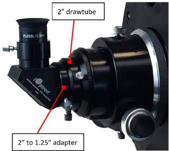
All RC scopes can accept 2" or 1.25" eyepieces, via a 2" to 1.25" adapter.
Always begin viewing with the lowest power eyepiece. (Note: a 20 mm focal length eyepiece is lower power than a 10 mm one.) A formula can be used to determine the power of each eyepiece: Telescope focal length divided by eyepiece focal length equals magnification. For example, a RC8 has 1600mm in focal length, the magnification with a 20mm lens is:
$$ 1 6 0 0 \mathrm{mm} \div 2 0 \mathrm{mm} = 8 0 \mathrm{X} $$
Focusing Telescope
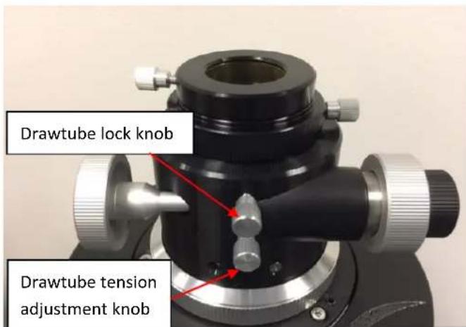
All iOptron RC telescopes come with a dual-speed Crayford focuser. Each focuser is also equipped with both a tension adjustment knob for the drawtube and a drawtube locking knob. We recommend keeping the tension adjustment knob fairly tight at all times as this will minimize drawtube flexure and slippage.
The 6" RC features a 2" Crayford focuser equipped with a removable 1.25" adapter. The tension adjustment knob and the drawtube locking knob are on the underside of the focuser,
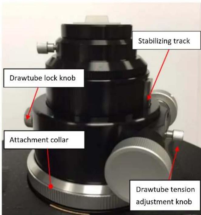
The 8" RC has a 2" linear-bearing Crayford focuser, which has a stabilizing track on the underside of the drawtube that provides extra rigidity for carrying heavy payloads. The tension adjustment knob is on the underside of the focuser while the larger locking knob is on top.
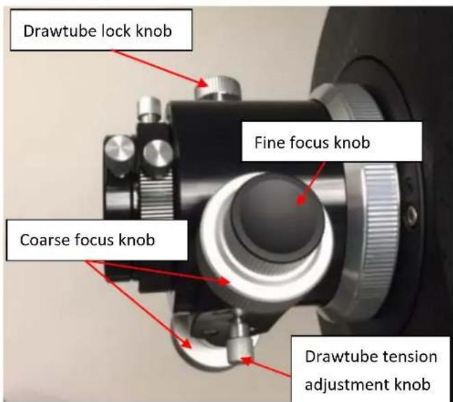
The 10" RC also boasts a linear bearing focuser, but with an oversized housing and a larger 3.3" drawtube that terminates in a 2" accessory collar. It has a stabilizing track, too. The tension adjustment knob is on the underside of the focuser while the larger locking knob is on top.
Point the telescope so the front end is aimed in the general direction of an object you wish to view. Release drawtube lock knob so the drawtube can be moved while turning the focus knobs. Select a proper diagonal and eyepiece if you are doing visual observation. Adjust the drawtube tension adjustment knob for a proper tension during adjust the focus knob. Look through the eyepiece while turn the coarse focus knob to move the drawtube outward until you see the image. Turn the fine focus knob until the image becomes sharp. Go a little bit beyond sharp focus until the image just starts to blur again. Then reverse the rotation of the knob just to make sure you've hit the exact focus point. You will have to readjust the focus when aiming at subjects of varying distances, or after changing eyepieces.
If the focuser drawtube is fully extended and you are still unable to achieve focus, you will need to install one or more extension rings (see next section).
Practice this during daytime by aiming the main telescope tube at a land-based target at least 12 miles away.
The focuser can be rotated to a desired angle prior to
final focusing for astrophotographic framing by slightly loosening the focuser attachment collar (turning it counterclockwise), then rotating the focuser to the desired position, then retightening the collar.
Use of Optional Accessories
Your telescope does not come with eyepieces and diagonal so as to offer the greatest flexibility in configuring it to your needs.
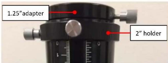
The 2" compression ring accessory holder accepts 2" eyepieces, star diagonals, camera adapters, etc. There are several accessories that come with the RC OTA. One is a 1.25" compression ring adapter that slips into the 2" holder. This lets you use optional 1.25" accessories (eyepiece, star diagonal, camera adapter, terrestrial image erecting diagonal, CCD/CMOS camera, etc.)
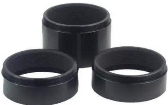
Also included with the telescope are three threaded-on extension rings: one 2" long and two 1" long.
natural_image
Three black plastic cylindrical components arranged in a triangular formation (no text or symbols visible)These extension rings are provided to allow multiple visual or photographic accessories to reach focus, depending on their backfocus requirements. They are designed for installation individually or in combination between the optical tube and the focuser to take up unneeded backfocus.
If the focuser drawtube is fully extended and you are still unable to achieve focus you will need to install one or more extension rings.
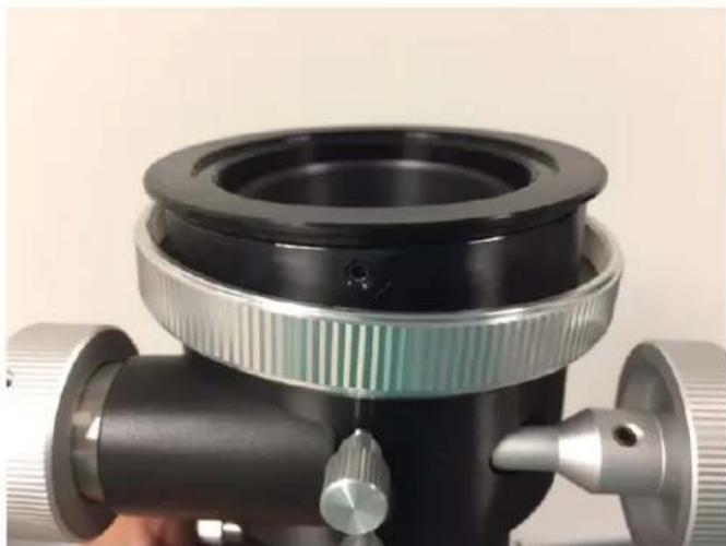
(1) First remove the focuser from the optical tube by rotating the focuser attachment collar counterclockwise (a RC8 is shown).
natural_image
Close-up of a black optical instrument with measurement scale and pointer, no visible text or symbols on the device itself.The focuser was removed from the scope.
natural_image
Close-up of a mechanical optical device with metallic and black components, no visible text or symbols(2) Install one extension ring, here is a 2" long one. Thread it onto the telescope firmly. You may add
more than one rings depends on your equipment.
natural_image
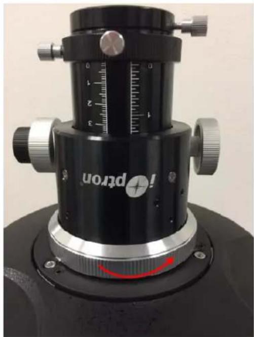
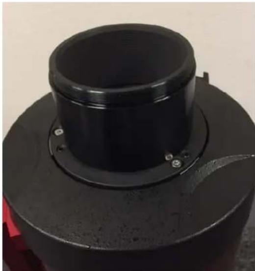
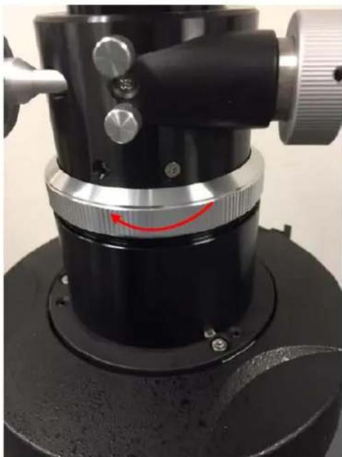
Close-up of a black cylindrical mechanical component with a flanged top and bolted base (no visible text or symbols)(3) Once you have threaded on the desired number of extension rings onto the male threads on the telescope tube, re-attach the focuser by aligning the silver attachment collar over the exposed extension ring threads and tighten by carefully turning clockwise.
natural_image
Close-up of a black mechanical optical instrument with a red curved arrow indicating rotation (no text or symbols visible)Be careful not to cross-thread any of the focuser components when and if changing them in the dark.
It may be useful to experiment with different combinations during the day before heading out into the field. Choose a target over half a mile away to ensure you are simulating infinity focus. The goal is to reach focus with as little extension of the focuser drawtube as possible, to avoid drawtube flexure. Depending on what equipment you use to observe or image with, such as focal reducer or flattener, filter wheel, or off-axis guider, you may need to add one or more of the included extension rings.
Cooling the Telescope
Before observing or photographing with your RC, you should let it equilibrate to the outdoor temperature for an hour or more. This will reduce thermal air currents inside the telescope that could soften or blur your images, whether you're doing visual observing or astrophotography. Due to the size of its optics, the 10" RC is equipped with three small DC cooling fans on its rear cell to help accelerate the cool-down time.
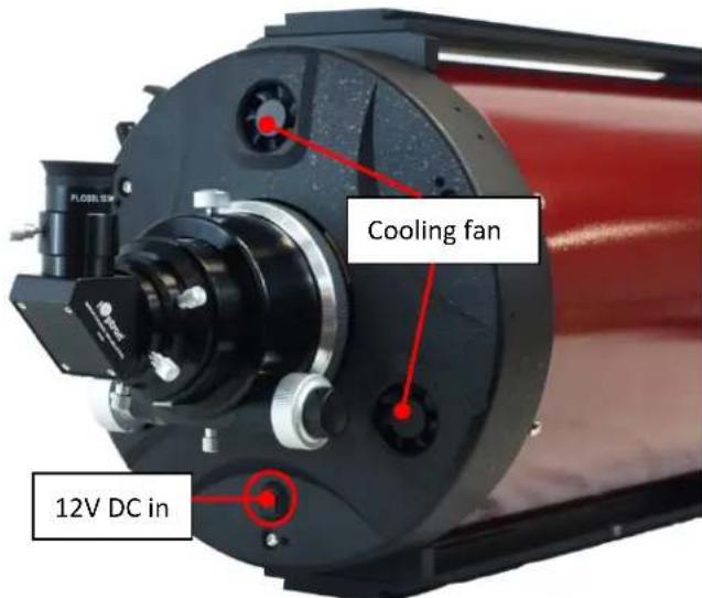
The fans pull outside air in through the rear cell and blow it onto the back of the primary mirror and out the front of the telescope. It's best to point the telescope upward when the fans are on to allow the heat to more efficiently escape. The fans require a 12V power supply; a battery holder using 8 AA batteries is
included with the 10" RC. The cable from the battery holder plugs into the DC power jack on the rear cell. The fans can also be powered by other 12V DC power supply, such as a iOptron PowerWeight (#8128) or other portable battery. The DC plug is 5mm/2.1mm, center positive. We recommend turning them off while actively observing or imaging to avoid any effect on the view from vibration or blowing air.
Aligning Finderscope
The Photron system comes with a straight-through finderscope, which has a quick-release bracket. The finderscope mounting ring has three collimating screws for precise alignment with the main scope optics. The quick-release bracket slips into a dovetail mounting base (mounting shoe) at the rear of the scope during use.
First, look through main telescope tube and establish a well-defined target (see focusing telescope section). Tighten all lock knobs of your mount (declination, right ascension, latitude and azimuth axes) so that telescope's aim is not disturbed. Then look through the finderscope and adjust the three collimation screws to center the object in the finderscope. Now, objects located first with the finderscope will be centered in the field of view of the main telescope.
Collimating the Ritchey-Chrétien
The optics in your new Ritchey-Chrétien optical tube have been aligned and collimated at the factory. However, rough handling during transit may cause them to be knocked out of collimation and periodic re-adjustments are required. A Cheshire eyepiece is needed to check and adjust collimation. The rough adjustments of primary and secondary mirrors can be done indoors while a more rigorous start test needs to be performed in the field.
Collimation Check
Get the telescope ready for collimation check in three steps.
- Remove any extension rings and attach the focuser directly to the optical tube.
- Set up the telescope in a well-lit room with the telescope oriented horizontally, and point it at a white or light colored wall.
- Insert the Cheshire eyepiece into the focuser via the included adapter and tighten the thumbscrew. Make sure a bright source of light such as a ceiling light or flashlight is aimed at the 45° reflecting surface of the Cheshire.
Look through the Cheshire eyepiece, as shown in the schematic below, a small black dot and a dark ring within a larger bright circle can be seen. The dot is the hole of the Cheshire eyepiece. The dark ring is the center mark on the secondary mirror. And the bright circle is the reflective 45-degree surface of the Cheshire. The larger black circle outside that are the secondary mirror and its holder.
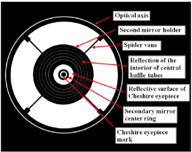
If the scope is in good collimation, the black dot will be dead center in the dark ring, which will in turn be centered in the bright circle. If that's the case, no further adjustments to the secondary mirror will be necessary. The optical axis is denoted by a thin white circle on the outer edge. If this outline is a perfect circle of uniform thickness, no further adjustments to the primary mirror is needed.
Secondary Mirror Adjustment
If the view looks something like the following figure with the dot of the collimation eyepiece NOT centered in the secondary center ring, the secondary mirror needs be adjusted.

natural_image
Abstract black-and-white circular pattern with concentric rings and a central swirl (no text or symbols)There are three collimation set-screws at the front of the secondary mirror holder. This will adjust the tilt of the secondary, changing the relative position of the secondary center ring when peering through the collimation eyepiece.
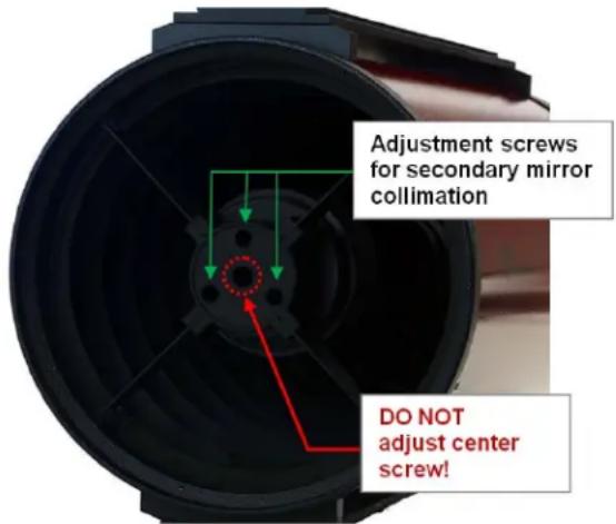
NOTE: DO NOT adjust the center screw! Only adjust the three screws around the perimeter of the holder! Adjusting the center screw can cause the secondary mirror to fall off and will not be covered under warranty.
A 4mm hex key is needed to perform collimation on the secondary mirror. When one of these screws is adjusted counter-adjustments need to be made to the other two. In other words, if one screw is loosened the other two need to be tightened, and vice versa. At the end of the process all three collimation screws should be reasonably tight so the secondary mirror won't shift while the scope is in use.
Always start by loosening one screw. Adjust the screws only very slightly—by no more than 1/8 turn at a time, and one screw at a time before checking the view through the Cheshire again to see how things changed. Only tiny adjustments should be required to achieve collimation. This will also aid in the prevention of accidentally putting the telescope grossly out of collimation. With each tiny tweak of a screw, make a mental note of which way and how far the center dot moved, as that will inform which screw to turn next and by how much. Experiment with different combinations of loosening / tightening the three screws one by one until the collimation eyepiece's black dot is centered in the dark ring of the secondary mirror. The correct alignment of the secondary mirror is critical in determining if the optical axis requires alignment. Be sure the secondary mirror is properly aligned before proceeding to the next step.
Optical Axis (Primary Mirror) Adjustment
After done secondary mirror adjustment, if the optical axis, which is denoted by a thin outline of light (white) around the perimeter of the view through the collimating eyepiece, is not a perfect circle of uniform thickness, that means the optical axis (primary mirror) needs adjustment. A 3mm and a 2.5mm hex key are required for the 6" and 8" telescopes, and a 4mm and a 2.5mm hex key are required for the 10" telescope.

natural_image
Abstract black-and-white concentric circle pattern with radial lines and a central spiral (no text or symbols)There are total three pairs of screws on the rear cell of the optical tube where the focuser attaches. Each pair consists of a small black screw and a larger chrome screw.
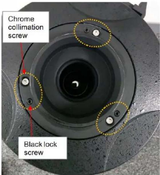
The small black screws are merely locking screws, which should be loosened before adjusting the mirror's tilt. The larger chrome screws are spring-loaded collimation screws that actually adjust the tilt of the primary mirror. Turn these collimation screws only a fraction of a turn at a time, for example, 1/8 turn. Turn one and check the view through the Cheshire to see if it improved the white optical axis ring. Keep tweaking the collimation screws, each time checking the optical axis ring, until it is concentric and uniform in width. Then tighten the three lock setscrews to fix the mirror in that position.
After adjusting the optical axis, re-check the collimation of the secondary mirror and make any necessary adjustments, then recheck the optical axis collimation. Generally, optical axis collimation will not need to be performed very often.
Star Testing
A star test can be used to further improve and confirm the collimation accuracy of the telescope. It needs to be performed in the night sky using a real star. Get the telescope ready for the star test.
- Remove the Cheshire eyepiece.
-
Install all extension rings between the telescope's rear cell and the focuser.
-
Insert an eyepiece directly into the focuser drawtube by using the 1.25" ring adapter. The eyepiece should provide moderate to high magnification.
• DO NOT use a star diagonal.
An ideal target is a star close to the zenith (straight overhead) rather than at the horizon to minimize atmospheric distortions. Using Polaris as your target star can be helpful as minimal drift adjustments will be required. Center the star in the field of view. Slowly de-focus the image with the focusing knob until you can see a series of concentric diffraction rings form around the dark disk in the center. That dark disk is the shadow of the secondary mirror.

natural_image
Concentric circular wave pattern with a central dark spot (no text or symbols)
natural_image
Concentric circles diagram with a central dot, no text or symbols presentIn a well collimated telescope, the diffraction rings should appear round and concentric, with the dark disk exactly in the center. If the dark central disk is off center, the scope is out of collimation. Adjust the collimation of the secondary mirror and, only if necessary, the primary mirror while monitoring the defocused star until the dark central disk is exactly centered in the diffraction rings. The adjustment procedure on the telescope mirrors is the same as described in Part 'Secondary Mirror Adjustment' and 'Optical Axis (Primary Mirror) Adjustment'.
NOTE: It is important when checking or adjusting the collimation using a star, that the star be positioned in the center of the eyepiece's field of view. If it isn't, the optics will always appear out of collimation, even though they may be perfectly aligned! It is critical to keep the star centered, so over time you may need to make slight corrections to the telescope's position.
Specifications:
| Photron RC6 RC8 RC10 | |||
| Optical design Ritchey-Chretien | Ritchey-Chretien Ritchey-Chretien | Chretien | |
| optical type Hyperbolic Hyperbolic Hyperbolic | |||
| Optical diameter 150mm | 200mm 250mm | ||
| Focal length 1370mm 1624mm 2000mm | |||
| Focal ratio | f/9 | f/8 | f/8 |
| Resolving power | 0.76 arcsec | 0.58 arcsec 0.46 arcsec | |
| Limiting stellar magnitude | 13.6 | 14.2 14.7 | |
| Lowest useful magnification | 22X | 29X | 36X |
| Highest useful magnification | 180X | 236X | 295X |
| Secondary mirror size | 67mm | 95mm | 110mm Dia |
| Eyepieces | None | None | None |
| Focuser | 10:1 Crayford dual speed | 10:1 Crayford dual speed | 10:1 Crayford dual speed |
| Focuser size | 2" | 2" | 3.3" |
| Dovetail bar Vixen-style | Losmandy-style | Losmandy-style | |
| Mounting bar (Top) | None | Vixen-style | Losmandy-style |
| Finderscope base | Yes | Yes | Yes |
| Finderscope None | None | None | |
| Tube material | Steel | Steel | Steel |
| Tube length | 19.1 in | 22.0 in | 28.4 in |
| Weight 12 lbs | 18 lbs | 35 lbs | |
| OTA cooling fan | No | No | Yes (three built-in fan, with battery holder) |
| Other accessories | 1.25" compression ring adapter1" extension tube X22" extension tube X1 | 1.25" compression ring adapter1" extension tube X22" extension tube X1 | 1.25" compression ring adapter1" extension tube X22" extension tube X1 |
| Warranty | One year | One year | One year |
Revised Sept 2017
- Photron Ritchey-Chrétien Optical Tube Assembly
- INSTRUCTION MANUAL
- Parts List
- Getting Started
- Mounting the Telescope
- Selecting an Eyepiece
- Focusing Telescope
- Use of Optional Accessories
- Cooling the Telescope
- Aligning Finderscope
- Collimating the Ritchey-Chrétien
- Collimation Check
- Secondary Mirror Adjustment
- Optical Axis (Primary Mirror) Adjustment
- Star Testing
Brand : iOptron
Model : Photron
Category : Telescope