
Inground 200 Single Color - Outdoor Lighting MARTIN - Free user manual and instructions
Find the device manual for free Inground 200 Single Color MARTIN in PDF.


| Product Type | 150W outdoor/indoor uplight for burial installation |
| Lamp Type | Philips CDM-SA/T 150W/942 (lifetime 9,000 hours) |
| Power Supply Options | 277 V 60Hz, 230 V 50Hz, 210 V 60Hz (factory-set, rewirable) |
| Ingress Protection | IP65/67 (immersion up to 30 minutes, low-pressure water jets) |
| Dimensions | Height 496 mm (19.53 in); Trim ring outer Ø 340 mm (13.39 in); Top flange outer Ø 310 mm (12.2 in) |
| Weight-Bearing Capacity | 5000 kg (11,000 lb) from pneumatic tire (direct or sleeve installation) |
| Beam Adjustment | Continuous tilt 0–15°; manual 360° pan rotation |
| Cooling | Passive via surrounding fill material; thermal cutout shuts lamp on overheating |
| Ambient Temperature Range | Up to 35°C (95°F) for direct burial; up to 25°C (77°F) for sleeve installation; above 35°C requires Martin consultation |
| Drainage Requirement | Installation well must drain water faster than it enters; base must not be submerged long-term |
| Anti-Humidity Sachet | Must be replaced with fresh sachet each time fixture is opened; close within 20 minutes of opening sealed aluminum bag |
| Cable Connections | 3 m (9.8 ft) hard-wired power cable tail; 3 m data cable tail (for CMY models only) |
| Installation Options | Direct burial or using Martin installation sleeve (recommended for hardscape/vehicular loads) |
| Sleeve Fill Material | Oven-dried fine sand, density 1500–1600 kg/m³, grain size 0.18–0.5 mm |
| Spare Parts Available | Front glass, seals, trim rings, screws, anti-humidity sachets, rock guards, etc. |
| Compliance | Installation by qualified professionals only; observe local safety regulations |
Frequently Asked Questions - Inground 200 Single Color MARTIN
User questions about Inground 200 Single Color MARTIN
0 question about this device. Answer the ones you know or ask your own.
Ask a new question about this device
Download the instructions for your Outdoor Lighting in PDF format for free! Find your manual Inground 200 Single Color - MARTIN and take your electronic device back in hand. On this page are published all the documents necessary for the use of your device. Inground 200 Single Color by MARTIN.
USER MANUAL Inground 200 Single Color MARTIN
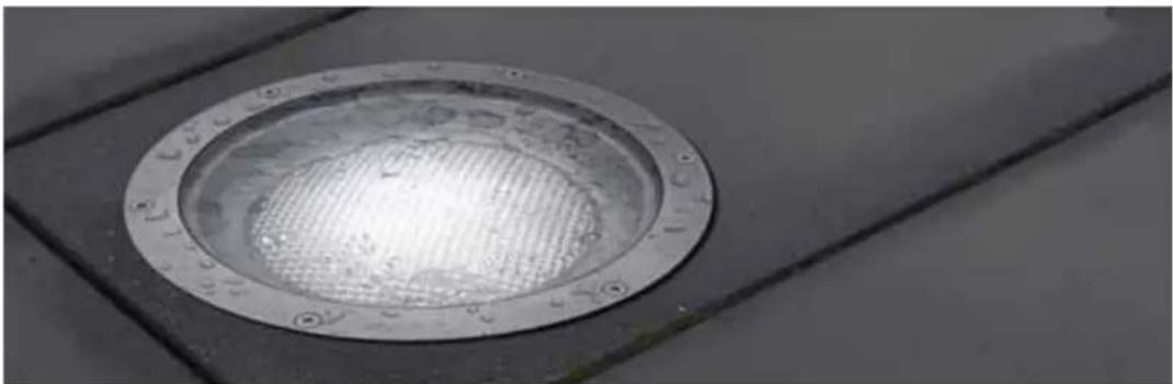
Inground 200 ^TM
natural_image
Close-up of a metallic circular drain cover with a grid pattern, mounted on a tiled floor (no text or symbols visible)Installation Guide
IMPORTANT!
Read this guide carefully before installing the Inground 200. If the Inground 200 is not installed exactly as described in this guide, heat and/or humidity build-up may cause unsatisfactory performance or even damage that is not covered by the product warranty. If you are in any doubt about the suitability of an installation site or method, please contact Martin for advice.
Dimensions
Measurements are in millimeters

natural_image
Technical drawing of a circular mechanical component with a 80-degree angular dimension label (no text or symbols beyond the dimension)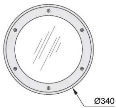
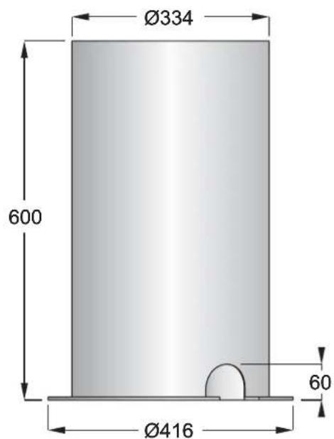

Installation sleeve Inground 200
Contents
1. Introduction ....5
Included items 5
Overview of installation procedure 5
Exploded view 6
2. Safety precautions ...... 6
Eliminating fire risk 7
Protecting the public. 7
3. Installation precautions....8
Avoiding corrosion....8
Cooling 8
Water resistance and drainage 8
Avoiding condensation and humidity 9
Stability and weight-bearing capacity....10
Disturbance by roots ....10
Service access....10
4. Physical installation....11
Safety 11
Installation options....11
Outdoor/indoor installation ....13
5. Cable Installation....14
Power cables and connections....14
Connecting power cables....15
Control data cables and connections (Inground 200 CMY only) .....15
Connecting control data cables (Inground 200 CMY only).17
6. Powering on and commissioning ..... 18
Commissioning procedure....18
7. Installation troubleshooting....22
8. Installation specifications....23
Inground 200 ^TM installation sleeve instruction note....24
Installing the sleeve 24
Installing the Inground 200 in the sleeve .....25
Installation sleeve specifications .....27
1. Introduction
Thank you for selecting the Martin ^™ Inground 200 ^™ , a 150 watt uplight designed for exterior burial installation.
This Installation Guide describes how to:
- prepare groundwork (installation well, etc.) before installation
- connect cables
- adjust the beam angle and have the Inground 200 ready for operation
For details of operating and servicing the Inground 200, please refer to the User Manual shipped with the product. The most recent versions of the User Manual and this Installation Guide are also available in the Support area of the Martin website at http://www.martin.com
Included items
The Inground 200 is supplied with the following items:
• Philips CDM-SA/T 150W/942 lamp (lifetime: 9 000 hours)
- Silica gel sachet inside fixture for shipping (must be removed and disposed of)
- Silica gel sachet packed separately in sealed aluminum bag (must be fastened inside fixture and fixture closed within 20 minutes of opening aluminum bag)
• DMX termination resistor
- 3 m (9.8 ft.) hard-wired power cable tail
- 3 m (9.8 ft.) hard-wired control data in/out cable tail
- Installation guide
- User manual
Overview of installation procedure
The suggested procedure for installing the Inground 200 involves two phases:
1. Pre-installation
- Read this Installation Guide carefully to familiarize yourself with all aspects of installation before planning or starting work.
- Ensure that a plan is available with details of site layout, beam aiming, power and control circuits, etc.
- Prepare installation wells and/or installation sleeves.
– see "Physical installation" on page 11
- see also "Inground 200^TM installation sleeve instruction note" on page 24
- Lay cables
– see "Cable Installation" on page 14
2. Installation
- Connect cables.
- see "Connecting power cables" on page 15 and "Connecting control data cables (Inground 200 CMY only)" on page 17.
- Install the fixture in the installation well or sleeve
- Open the fixture and replace the anti-humidity sachet, then apply power. – see "Powering on and commissioning" on page 18
- Adjust beam and close the fixture.
- see "Beam adjustment" on page 18
Exploded view

2. Safety precautions
Warning! This product is not for household use. Installation of the Inground 200 may only be carried out by qualified professionals.
This product presents risks of lethal or severe injury due to fire and heat, electric shock and lamp explosion.
Read this guide before installing the fixture. Follow all safety precautions listed in this guide. Observe all warnings in this guide and on the fixture.
Before attempting to operate the Inground 200, refer to the User Manual supplied with the product. The User Manual is also available in the Support area of the Martin website at http://www.martin.com
If you have any questions about how to install the fixture safely, please contact your Martin supplier or call the Martin 24-hour service hotline on +45 8740 0000, or in the USA on 1-888-tech-180.
Eliminating fire risk
The Inground 200 must be installed:
- Outdoors or in a well-ventilated area.
- At least 0.5 meters (20 inches) away from the surface to be illuminated.
- At least 1 meter (40 inches) away from any combustible materials.
Ensure that:
- Litter, dry leaves or other combustible materials cannot accumulate on or near the fixture.
- Vehicles or other fire risks cannot be left unattended over or near the fixture. This is particularly important in situations where a vehicle may be left unattended over or near an unlit fixture which is later switched on.
Protecting the public
To avoid injury to members of the public, install the Inground 200:
- In an area where accidental contact with the front glass is unlikely, since the Inground 200 becomes hot during normal operation.
- Flush with the surrounding surface, so as to eliminate any obstacle to pedestrians that might result in falls or injuries.
- With an anti-skid front glass (available from Martin dealers, circular etched P/N 91611238, design etched P/N 91611198) in pedestrian traffic areas.
Ensure all local safety regulations and legal requirements are observed, and take appropriate measures to warn or restrict access. To avoid accidents during installation or service, restrict access to the site and place both warning notices and barriers around all work areas until work is completed and all covers, etc. are correctly in place.
3. Installation precautions
Important! If the Inground 200 is not installed exactly as described in this Installation Guide, product performance may be unsatisfactory and the product warranty may be invalidated. In particular, the precautions listed below must be observed. Martin will gladly provide assistance in planning and carrying out installation. In some cases, Martin must be consulted and approval obtained in order to validate the product warranty. Such cases are listed below.
The Inground 200 installation location and method must be carefully chosen in order to avoid heat and moisture build-up and to ensure satisfactory performance over the product's lifetime.
Avoiding corrosion
Do not scratch or damage the outer surface of the Inground 200. The housing is carefully coated at the factory to protect it against corrosion, but if coatings are damaged this protection will be lost, invalidating the product warranty if corrosion should occur.
Cooling
The Inground 200 generates heat that must be both absorbed by and conducted through the surrounding fill material as effectively as possible. If the fixture is not installed exactly as described in this guide, cooling may be insufficient and the fixture may tend to overheat.
The following precautions apply:
- Do not install the Inground 200 above ground level in the open air or in any type of container.
- Do not use fill material with a low density or insulating properties.
- Eliminate as much air as possible from the material surrounding the fixture or installation sleeve by compacting it during installation.
- If an installation sleeve is required, use only the sleeve available from Martin.
- In locations where the ambient temperature exceeds 35^ (95° F), careful heat management is necessary and you must obtain assistance from Martin to ensure satisfactory operation. In such locations, the Inground 200 product warranty is only valid after consultation with and by agreement with Martin.
Overheating will reduce the lifetimes of critical components. A thermal cutout on the PCB shuts down power to the lamp if the fixture's internal temperature exceeds safe limits. Intermittent lamp cutouts are a sign of critical overheating. Martin cannot be held responsible for intermittent lamp shutdowns or heat damage caused by an unsuitable installation method and/or location.
Water resistance and drainage
The Inground 200 has an ingress protection rating of IP 65/67. This means that the fixture can withstand immersion for 30 minutes and low-pressure water jets. However, it is not designed to withstand constant immersion.
Immersion will encourage condensation inside the fixture: a GoreTex valve in the base of the fixture equalizes pressure as the fixture heats up and cools down. The valve allows air into the fixture but prevents the entry of water. If this valve is under water while the fixture cools down, it will not be able to equalize the pressure in the fixture and humidity may be drawn past seals and into the fixture by suction.
The following precautions apply:
- The base of the Inground 200 must not be submerged in water other than for very short periods. If in doubt about a particular site, consult a geotechnical engineer.
- Effective drainage that can prevent any buildup of water in the installation well in all situations is absolutely essential and must be provided and tested before the Inground 200 is installed. It must be possible for water from rain, melting snow, flooding or other sources to drain out of the installation well or sleeve at least as fast as it can enter it. If water is present in the installation well for extended periods, the product warranty will be invalidated.
- To minimize the risk of flooding or waterlogging, install the fixture in a location which is above the level of the surrounding area and make sure drainage conditions are adequate.

natural_image
Diagram of a water source with raindrops and a smiley face icon, no text or symbols present
natural_image
Diagram of a water spray device with raindrops falling through it, showing airflow and a sad face emoji (no text or symbols)Avoiding condensation and humidity
Each time the Inground 200 is opened, the silica gel anti-humidity sachet fastened to the lamp module must be removed and a new item fastened in its place (see "Commissioning procedure" on page 18).
Excess humidity inside the fixture can be experienced in the following situations:
• The installation well is waterlogged
- The trim ring and front glass are not sealed correctly on the top of the housing.
- The anti-humidity sachet fastened to the lamp module is saturated or missing.
Clearing excess humidity
Warning! If you clear excess humidity as described below:
- The exposed lamp and internals present a risk of electric shock, burns and ultra-violet radiation. A hot discharge lamp is under pressure and there is a risk of lamp explosion. Block public access, wear safety glasses and heat-resistant gloves, handle the lamp module with care, and do not look into the light beam.
- Choose dry weather.
- Ensure that no dust or objects enter the fixture while it is open.
If there is excess humidity in the Inground 200, condensation will appear under the front glass. To eliminate excess humidity:
- Check that the installation has adequate drainage and that the top glass and trim ring are sealed correctly. Rectify any problems.
- Install a new anti-humidity sachet and reinstall the front glass (see "Commissioning procedure" on page 18). New anti-humidity sachets are available from Martin suppliers (see "Ordering information" on page 23).
Stability and weight-bearing capacity
If the Inground 200 will only be subjected to light loads on the front glass, install it directly in the ground in a direct burial installation (see "1. Direct burial" on page 11)
If the Inground 200 is to be installed in a location where vehicles are likely to put weight on the fixture, use an installation sleeve (see "2. Installation sleeve" on page 12).
Disturbance by roots
The further the fixture is located from vegetation such as trees, hedges or bushes, the less chance there is that the growth of roots will disturb the fixture or even cause damage to the fixture and its cables. If the fixture is to be located close to vegetation, consult a landscape architect about the possibility of disturbance by root systems.
Service access
All internal components in the Inground 200 can be accessed through the top of the fixture without having to remove the housing from its installation site.
4. Physical installation
Safety
The Inground 200 must be installed in a location that meets the safety standards listed under "Safety precautions" on page 6. It is the installer's responsibility to ensure that all local safety regulations and legal requirements are observed.
Installation options
There are two methods of installing the Inground 200:
-
Direct burial
-
Installation sleeve
1. Direct burial
Burying the Inground 200 directly in the ground is recommended:
• in landscape installations
- in locations where the top of the fixture will not have to support heavy loads (from vehicles, for example)
- in locations where the ambient temperature exceeds 25^ (77°F).
While the Inground 200 itself will bear up to 5000 kg (11,000 lb.), the ground underneath the fixture in direct burial installations may allow the fixture to sink if heavy loads are applied to the top of the fixture. In hardscape locations and in landscape locations where heavy loads may be placed on the fixture, an installation sleeve is an easy solution to ensure stability. However, if the ambient temperature exceeds 25^ C ( 77^ F), direct burial will ensure better cooling.
Direct burial: examples
The example installations below show how an Inground 200 can be buried directly, but the installer must make allowance for local conditions:

It is vital to ensure that the base of the housing rests firmly on a strong foundation, so that pressure on the top of the fixture will not press the fixture into the ground. One possible way of achieving this is to pack crushed stone or hardcore firmly in the bottom of the installation well.
Important! When creating a strong foundation for the Inground 200, remember to allow for drainage.
The level of the fill material immediately around the top of the housing must be kept just below the level of the top of the housing, otherwise it will create an obstruction for the trim ring. This will make it impossible to fasten the trim ring correctly onto the top of the housing to seal the product correctly, and will cause excess humidity inside the fixture.
The fill material that is in direct contact with the fixture's housing must conduct heat away from the fixture. Do not use lightweight aggregates or other insulating materials for filling, since these will encourage overheating.
If possible, install the Inground 200 in a poured concrete encasement after all connections have been made and double-checked.
Ensure that cables are not stressed or crushed during installation, and ensure that the housing rests on its base, and not on the cables.
2. Installation sleeve
A steel installation sleeve for the Inground 200 is available as an accessory. Installation instructions are supplied with each sleeve, available on the Martin website and included at the end of this guide (see "Inground 200^TM installation sleeve instruction note" on page 24).
The Inground 200 in a correctly installed drive-over installation sleeve will support a weight of 5000 kg (11,000 lb.) from a vehicle tire.
Important! The installation sleeve is not recommended in locations where the ambient temperature exceeds 25^ C ( 77^ F).
Use of an installation sleeve is recommended for hardscape locations (tarmac, stone paving, etc.) and in landscape locations where the Inground 200 groundwork may be subjected to loads from pedestrians or vehicles (including grasscutting or gardening equipment, motorcycles, emergency services, etc.). Use of an installation sleeve will also allow work to be carried out in two stages:
- Pre-installation (excavation, conduit-laying and groundwork preparation). This can be carried out by construction personnel.
- Installation (cable pulling and connection, fixture installation and adjustment). This must be carried out by qualified electrical personnel only.
Sleeve installation: example
The example installation below shows how adequate support and drainage can be achieved, but the installer must make allowance for local conditions. Note that the empty space around the fixture in the illustration below must be filled with sand to complete the installation.

natural_image
Diagram of a cylindrical tank with a hose inserted into a granular material, placed on a textured surface (no text or symbols)Temporary installation sleeve cover
To avoid rainwater and dirt gathering in empty installation sleeves while waiting for the Inground 200 to be installed in them, a temporary cover is supplied with each sleeve.
Important! The temporary installation sleeve cover is not designed to support weight, so ensure that pedestrians and vehicles are kept away from the sleeve by using warning notices and barriers.
Outdoor/ indoor installation
The Inground 200 was developed with outdoor installation in mind but can be installed indoors provided that all the guidelines in this installation guide are followed. This applies particularly to ambient temperature considerations.
5. Cable Installation
Warning! All electrical system installation must be performed by qualified professionals.
It is the installer's responsibility to ensure that all local safety regulations and legal requirements are followed when installing the Inground 200.
This section describes how to connect the Inground 200 to AC power. For Inground 200 CMY models, it also describes how to connect control data cables.
All Inground 200 models are supplied with a power cable tail installed ready for connection to mains power. Inground 200 CMY models are supplied with a data cable tail installed that contains both DMX data in and out conductors ready for connection to a control data link.
All external connections must be protected inside suitable waterproof junction boxes or as required by local laws, regulations or codes. The ends of Inground 200 cables must not be allowed to come into contact with water or moisture, as the vacuum created in the product during cooldowns can suck moisture up cable and into the fixture.
Cable slack.
Allow at least 80cm (2ft 8in) of free cable in the installation well or sleeve so that the fixture can be lifted clear for service without disconnecting cables.

Power cables and connections
Warning! For protection from potentially lethal electric shock:
• The Inground 200 must be grounded (earthed).
- The AC power supply must be fitted with a fuse or circuit breaker, ground-fault (earth-fault) protection, and a means to isolate the fixture from power during service or when not in use.
- Cables and fixtures must be isolated from power, and steps taken to prevent reconnection, before carrying out any work on them.
- Before applying power, check the product serial label to ensure that the product can accept the local mains power voltage and frequency.
Important! Do not connect the Inground 200 to an electrical dimmer system: doing so can damage the electronics.
Power settings
The Inground 200 is factory-configured for one of the power settings listed in Table 1 below. The factory power supply settings are printed on the product serial number labels outside and inside the housing. If your local AC voltage or frequency differ from the settings for your model, the fixture's power supply must be rewired by an authorized Martin service dealer.
| Voltage | Frequency |
| 277 V 60 Hz | |
| 230 V 50 Hz | |
| 210 V 60 Hz |
Table 1: Default Power Settings
Connecting power cables
Connect the conductors in the power cable tail to a source of mains power as follows:
EU models (230 V, 50 Hz models) mains power connections
- Connect the yellow/green wire to ground (earth)
- Connect the blue wire to neutral
- Connect the brown wire to live
US models (210 V, 60 Hz and 277 V, 60 Hz models) mains power connections
- Connect the yellow/green wire to ground (earth)
- Connect the black wire marked 1 - ONE
- Connect the black wire marked 2 - TWO
Table 2 below shows the standard wire identification schemes in the EU and USA; consult an electrician if you have any doubts about proper installation.
| Wire (EU) Wire (US) Function Marking Screw (US) | ||||
| brown black live “L” yellow or brass | ||||
| blue white neutral “N” silver | ||||
| yellow/green | green | ground | ⊥ or ⊕ | green |
Table 2: Mains Connections
Control data cables and connections (Inground 200 CMY only)
Inground 200 CMY models require a control data link for DMX controller operation and for synchronized stand-alone operation of multiple fixtures.
Control cable type and connector pinout
Use only RS-485 (now known as EIA-485) data cable designed for burial for the data link. RS-485 cable has low capacitance and a characteristic impedance of 85 to 150 ohms. It is electrically shielded and has at least 1 twisted-pair of conductors. The minimum wire size is 0.2mm^2 (24 AWG) for runs up to 300 meters (1000 ft.) and 0.322mm^2 (22 AWG) for runs up 500 meters (1640 ft).
XLR connection
A male 3-pin XLR connector can be fitted at the controller end of the data link to allow a standard connection to Martin DMX controller and uploader devices. The XLR connector should be wired as follows:
- Pin 1: shield
• Pin 2: DMX data cold (-)
• Pin 3: DMX data hot (+)
Note: to avoid ground/earth loop interference, make sure the DMX cable shield does not come into contact with the shell or body of the XLR connector.
RJ-45 connection
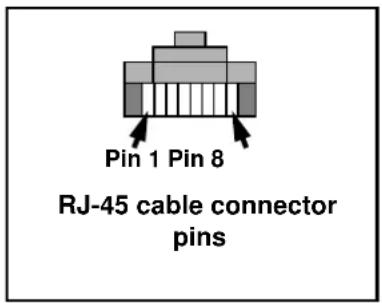
If an RJ-45 connector is used to connect the data link to DMX controller and upload devices, it must be wired according to the 568-B system using the standard RJ-45 pin-out for DMX applications:
• Pin 1: DMX data hot (+)
• Pin 2: DMX data cold (-)
- Pins 7 and 8: shield
RJ-45 cable connector pins are numbered from the left looking at the face of the connector with the locking clip on top.
Control cable layout
The following considerations must be taken into account when planning the layout of DMX control cables:
- The maximum permitted control data cable length is 500 meters (1640 ft). If more than 500 meters of control data cable will be necessary, contact your Martin dealer for advice.
- Long parallel runs of AC power and control data cables should be avoided. Even if not required by law, separate conduits are recommended for power and data cables.
- Fixtures must be 'daisy-chained', i.e. DMX must be connected in one single chain containing a maximum of 32 fixtures.


- An optically isolated amplifier-splitter such as the Martin RS-485 Opto-Splitter (P/N 90758060) must be used to:
- extend a control data link beyond 500 meters (1640 ft.), or
- branch the daisy-chained link into further single chains, each containing a maximum of 32 devices. The Martin Opto-Splitter allows a link to be branched into four new chains, or
- extend the link if the maximum of 32 devices is reached.
- The last fixture on the data link (or on each chain if you have branched the link) must be terminated with a 120 Ohm DMX termination resistor (supplied with CMY fixtures and also available from Martin, P/N 04150308) connected across the data out hot (+) and data out cold (-) wires. Note that this only applies to the last fixture in the chain. No resistor should be used on the other fixtures.
Connecting control data cables (Inground 200 CMY only)
Connect the conductors in the Inground 200 CMY's data cable tail to the control data link as follows:
- Connect one white wire to data in hot (+)
- Connect the red wire to data in cold (-)
- Connect the bare copper wire to shield
- Connect the other white wire to data out hot (+)
- Connect the blue wire to data out cold (-)
It does not matter which of the white wires is used for used for data hot (+) input and which is used for data hot (+) output. Similarly, it does not matter which of the red and blue wires is used for data cold (-) input and which for data cold (-) output. However, we recommend that red and blue wires are connected as indicated above for reasons of consistency.
On the last fixture on the data link (or on each chain if you have branched the link), connect a DMX termination resistor across the data out hot (+) and data out cold (-) wires in the cable tail.
6. Powering on and commissioning
After all connections and cables are installed and after the site has been made safe, the Inground 200 must be opened, the anti-humidity sachet fastened to the lamp module must be replaced, then the fixture must be powered on for testing and beam adjustment, and finally the fixture must be closed.
When fixtures are powered on, lamps strike after a short delay.
Inground 200 CMY test sequence
When Full Spectrum CMY models are powered on for the first time, they will run through a factory-set light show for test purposes. They will continue to run this test sequence until they are programmed.
Test sequence scenes
The CMY fixture is pre-programmed with 5 scenes to verify that all CMY flags and the dimmer are working correctly:
- White 100% intensity.
- Cyan 100% intensity.
- Magenta 100% intensity.
- Yellow 100% intensity.
- White 0% intensity (no light).
Beam adjustment
Correct adjustment of the beam of the Inground 200 is critical for correct illumination of the target.
Adjustment must be carried out with the lamp powered on and is best carried out after dark.
Anti-humidity sachets
During the commissioning procedure (and each time the fixture is opened for service), the silica gel anti-humidity sachet inside the fixture must be removed and replaced with a fresh one before closing the fixture. New sachets can be obtained from Martin dealers:
- 1 sachet in sealed aluminum packet – P/N 37220000
- 10 sachets in one sealed aluminum packet (Service Kit) – P/N 37220001
The Inground 200 is supplied with one silica gel sachet fastened inside the fixture to protect from humidity during shipping and one sachet supplied separately in an aluminum foil bag.
Commissioning procedure
Warning! Danger of burns, electric shock and lamp explosion!
- This procedure must be carried out by authorized electrical personnel and in clean, dry conditions only.
- Wear heat-resistant safety gloves and safety glasses throughout this procedure.
- Do not look directly into the lamp.
- Make sure that nothing falls into the fixture while the front glass and lens are removed.
Important! Any damaged seals or screws must be replaced with new items. Two spare countersunk Torx screws for the trim ring are supplied with the fixture.
The front glass seal, its seating surface in the housing, the front glass and the trim ring must all be perfectly clean and dry during re-installation to maintain a waterproof seal.
Do not use liquid silicone gasket or any other kind of sealant on the front glass seal, front glass, housing or trim ring. Doing so will invalidate the product warranty.
Each time the Inground 200 is opened for service, or to clear excess humidity at any time, the silica gel anti-humidity sachet fastened to the lamp module inside the fixture must be removed and a new item fastened in its place. The fixture must then be closed within 20 minutes.
Besides safety gloves and safety glasses, you will need a torque driver with a range that includes 9 Nm (6.6 ft.-lbs.) as well as 4mm and 2.5mm Allen and Torx bits for these procedures.
To commission the Inground 200, leaving it ready for use by lighting operators:
-
Ensure that the fixture is isolated from power and that power cannot be applied, even accidentally.
-
Brush or if possible vacuum sand, dirt, etc. away and clean the top of the fixture and the surrounding area to ensure that dirt does not fall into the fixture.
-
Remove the six countersunk Torx 30 screws and lift the trim ring off the fixture

-
Taking care to avoid damaging the seal, lift off the front glass and its seal.
-
The lens is under the front glass, resting on the beam adjustment ring top sleeve on top of the lamp module. Lift the lens out of the fixture.
-
If a light spill limiter ring (shading plate) and/or a louvered anti-glare plate are installed under the lens, lift them out of the fixture.
-
Holding the lamp module by the beam adjustment ring top sleeve, gently lift the whole module upwards until it is clear of the housing.
-
See illustration below. Cut the cable tie holding the silica gel anti-humidity sachet to the side of the lamp module above the cooling fan and remove the sachet.

- Remove the new anti-humidity sachet supplied with the Inground 200 from its sealed aluminum packet and fasten it with a cable tie in the place of the sachet you have removed. You must now carry out the rest of the commissioning procedure and close the fixture within 20 minutes.
Earlier Inground 200 fixtures had a screw in the top of the housing and corresponding notches in the lens and beam adjustment ring top sleeve to make pan realignment easier after removal and reinstallation of the lamp module. This screw is now no longer fitted, making it impossible to place the beam adjustment ring top sleeve and lens on top of the screw by mistake and leave the Inground 200 difficult to seal correctly. If desired, small pieces of tape or blobs of paint can be used to mark the alignment of the lens, beam adjustment ring top sleeve and housing.
- Lower the lamp module into the housing, power the fixture on and check that it runs its test sequence correctly.
- Wait for a few minutes with the front glass off and the lamp powered on to allow the lamp temperature to stabilize and the fixture to reach optimum temperature for beam adjustment.
- See illustration below. For clarity, the lamp module is shown without the beam adjustment ring top sleeve and lens (see "Exploded view" on page 6 for an illustration of the complete assembly) but you do not need to remove the top sleeve. Rotate the lamp module in the top of the housing until it can be tilted towards the target.

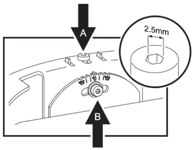
- Check that the beam adjustment ring screws (A) are pushed out towards the edges of the ring so that the retaining clips are engaged in the beam adjustment ring top sleeve, and check that the screws are tight so that the beam adjustment ring is clamped to its top sleeve.
- Loosen the tilt adjustment Allen screw (B) on the side of the beam adjustment ring. Adjust the tilt angle from 0 - 15° by pushing down gently on the side of the lamp module top plate. Retighten the tilt adjustment screw (B). If the entire module has been rotated to the correct pan alignment position in the top of the housing, and if the tilt has been correctly set, the lamp should now be aimed correctly.
- Refit the shading plate and anti-glare plate (if fitted) and lens by lowering them into the housing on top of the adjustment ring top sleeve.
- Check that the target is illuminated as intended. If not, repeat the readjustment procedure. When the desired illumination is obtained, the tilt angle can be read from the guide next to the tilt adjustment screw and noted for future reference.
- Power the fixture off.
- The front glass seal must be in perfect condition and show no signs of damage when you reinstall it, so check the seal carefully. Replacement front glasses and seals are available from Martin dealers (standard front glass: p/n 41700007, front glass seal: p/n 20600441).
-
Any dirt between the front glass seal and housing or front glass seal and trim ring will prevent a proper seal and encourage moisture build-up inside the fixture, so clean the mating surfaces carefully. The trim ring overlaps the top of the fixture and any hard obstruction immediately beside the fixture will prevent the trim ring from sealing properly, so ensure that a space the diameter of the trim ring around the top of the fixture is clear down to slightly below the level of the top of the housing.
-
Place the front glass complete with its seal in the top of the housing and place the trim ring over the front glass.
- Inspect the six countersunk Torx 30 screws from the trim ring. Threads must be clean and undamaged. Two spare screws are supplied with the fixture. Replacement screws are available from Martin dealers (P/N 08110803). To make future service easier, apply a small amount of copper-based or silicone grease to the threads of the trim ring screws.
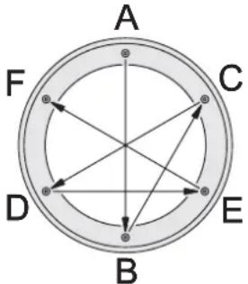
- See illustration below. Cross-tighten the trim ring screws as described here:
Important!
Tighten all the trim ring screws partially in the sequence illustrated below, then tighten all the screws partially again, then tighten the screws to the final torque. The torque of each screw falls when other screws are tightened, so when you seem to have reached the final torque, continue cross-tightening in the sequence shown below a further three times until all the six screws are tight to a torque of 9 Nm (6.6 ft.-lbs.). Do not exceed a final torque of 9 Nm (6.6 ft.-lbs.), or you may distort the trim ring and damage the seal. This will impair the Inground 200's waterproof properties and invalidate the product warranty.
7. Installation troubleshooting
| Problem Probable cause(s) | Remedy | |
| Excess moisture build-up in fixture (condensation under front glass). | Inadequate front glass sealing. | Ensure that front glass and trim ring make a correct seal in top of fixture housing. Check that there are no obstructions under the trim ring that may have prevented it from fastening down correctly onto the top of the housing.Ensure that trim ring screw torque is 9 Nm (6.6 ft.-lbs.).Replace front glass seal if damaged. |
| Silica gel anti-humidity sachet fastened to lamp module is saturated or missing. | Install a new sachet and close fixture within 20 minutes of opening new sachet's aluminum bag | |
| Flooded installation well. Improve drainage. | ||
| Fixtures cut out after 1 - 3 hours. Problem is relieved if water is poured into fill material around fixture. | Temperature too high: thermal cutout shutting down power to avoid overheating. | Modify fill material in sleeve to improve heat conduction away from fixture. |
| No response from fixture when power is applied. | No power to fixture. Check power cables. | |
| Mains fuse blown. Replace fuse. | ||
| No light, lamp cuts out intermittently, or burns out too quickly. | Lamp blown. Disconnect fixture and replace lamp. | |
| Fixture or lamp is too hot. | Allow fixture to cool. If problem persists, contact service technician. | |
| Fixture resets but does not respond correctly to DMX controller (CMY models only). | Controller not connected. Connect controller. | |
| Incorrect addressing of the fixtures. | Check address setting on fixture and controller. | |
| Bad data link connection. | Inspect connections and test cables. Repair or replace as necessary. | |
| Conflict between tracking and vector control. | Eliminate scene cross-fade on controller or set channel 6 to 0%. | |
| Data link not terminated. | Insert 120 Ohm resistor across DMX output conductors of data cable of last fixture on link. | |
| Defective fixture or 2 devices transmitting on link. | Check that only one fixture is set to operate as master.Bypass fixtures one at a time until normal operation is regained. | |
| Fixture does not reset correctly (CMY models only). | Electronic or mechanical failure. | Contact service technician. |
8. Installation specifications
Dimensions
Height 496mm (19.53in.)
Trim ring outer ∅ 340mm (13.39 in.)
Trim ring thickness 7mm (0.28 in.)
Top flange outer ∅ ....310mm (12.2 in.)
Included Items
User manual, Inground 200 P/N 35000153
Installation guide....P/N 35000151
Philips CDM-SA/T 150W 942 lamp.... P/N 97010111
Silica gel anti-humidity sachet (inside product, must be removed during installation)
Silica gel anti-humidity sachet (separate, must be fastened in fixture during installation)
Two spare trim ring screws (Torx, countersunk)
Weight-bearing capacity
Front glass (load from pneumatic tire) 5000 kg (11,000 lb.)
Inground 200 in installation sleeve with suitable groundwork ....5000 kg (11,000 lb.)
Connections
AC power in 3 m (9 ft. 10 in.) cable tail
Control data in/out ....3 m (9 ft. 10 in.) cable tail, 5-conductor data in/out
Related items
MUM (Multi Utility Manager) incl. DABS interface & cables P/N90758090
Ordering information
Anti-humidity sachet in sealed aluminum bag P/N 37220000
Ten anti-humidity sachets in sealed aluminum bag (Service Kit) P/N 37220001
Front glass P/N 41700007
Front glass seal P/N 20600441
Connections compartment/power compartment seal P/N 20600450
Installation sleeve, bevelled mount P/N 91611194
Installation sleeve, flush mount P/N 91611215
Trim ring kit, bevelled, aluminum P/N 91611210
Trim ring kit, bevelled, brass P/N 91611211
Trim ring kit, flush mount, aluminum P/N 91611213
Trim ring kit, flush mount, brass P/N 91611214
Trim ring screw (Torx, countersunk) P/N 08110803
Tamperproof hex screws (6 pcs.) and key P/N 91611200
Anti-skid front glass, design etched.... P/N 91611198
Anti-skid front glass, circular etched....P/N 91611238
Eyelid P/N 91611201
Ring louver P/N 91611202
Rock guard kit, steel P/N 91611199
Rock guard kit, brass P/N 91611208
Rock guard kit, aluminum P/N 91611209
For current product specifications and ordering information, please refer to the Inground 200
Product Support pages on the Martin website at http://www.martin.com
Inground 200 ^TM installation sleeve instruction note
The Inground 200 installation sleeve is recommended for hardscape locations and all locations with vehicle traffic. It is not recommended for locations where the ambient temperature exceeds 25^ C ( 77^ F). Sleeves are supplied in either flush or bevelled mount models. The flush mount model is recommended for areas with traffic.
Warning! Ensure that supply cables cannot be connected to AC power during installation.
The sleeve is supplied with this instruction note, 3 clamps and a steel cover/guide plate for use while filling the sleeve.
Installing the sleeve
To install the Inground 200 installation sleeve:
A

natural_image
Isometric illustration of a pipe passing through a circular opening with brick walls, no text or symbols presentPrepare the groundwork. Test to ensure adequate drainage. Ensure that the foundation will withstand loads on the fixture (from vehicles, for example).
B

natural_image
Isometric technical diagram of a mechanical or electrical component inserted into a channel, with no visible text or symbols.Put the sleeve in position. Cutouts are provided for cable conduit. Place a straightedge across the top of the sleeve and adjust height so that the sleeve will be flush with the finished surrounding surface.
C

natural_image
Isometric diagram of a pipe installation inside a tiled wall, showing a cylindrical component and support structure (no text or symbols)Fill around the sleeve. Earth or poured concrete are suitable. If filling with earth, compress it in layers during filling so that the earth is as compact as possible.
D
natural_image
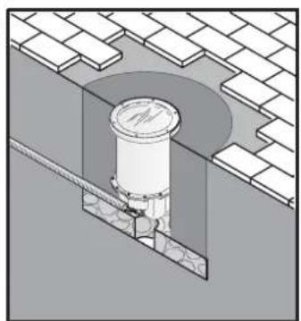
Isometric technical diagram of a mechanical component inserted into a channel, showing internal structure without any text or symbols.Install the fixture in the sleeve (see instructions on next page).
E

natural_image
Technical diagram of a pipe fitting mounted on a wall, with no visible text or symbolsFinish the surface around the fixture (flush mount model illustrated).
F

natural_image
Simple line drawing of a circular object on a woven background (no text or symbols)The finished installation.
This procedure must be carried out by an authorized electrician.
Ensure that cables cannot be connected to AC power during installation.
Use of a vacuum cleaner is recommended for some parts of this procedure.
Approximately 40 kg (88 lb.) of oven-dried fine sand that conforms to the following specifications is required as fill material in each installation sleeve:
Density.....1500-1600 kg/m3 (94-100 lb./cu.ft.)
Grain size ....0.18-0.5 mm (0.007-0.020 in.)
Suitable sand can be obtained locally or ordered from Martin in 25 kg (55 lb.) bags (P/N 91611237).
To install the Inground 200 in an installation sleeve:
-
Remove the Inground 200's front glass, lens and lamp module as described in the Installation Guide.
-
Place the fixture next to the installation sleeve. Connect all cables, tighten cable glands and tighten any blanking plugs used as described in the Installation Guide.

The installation sleeve is supplied complete with 3 clamps to hold the fixture in the sleeve (see illustration above). Clamp the Inground 200 into the sleeve as described below:

- Pass a 5mm Allen cap clamp bolt (A) through one of the three recessed holes in the top of the housing (B) and screw the bolt through a clamp block (C).

- Screw a self-locking retaining nut (D) onto the end of the clamp bolt until the nut is flush with the end of the bolt.

- Do not screw the nut any further up the bolt.

- Unscrew the bolt back up through the clamp block until the retaining nut touches the clamp block.

natural_image
Simple line drawing of a cylindrical container with a downward arrow indicating a drop or direction (no text or symbols)- Holding the Inground 200 by the inside rim of the housing, begin lowering it into its sleeve.

- As you lower the Inground 200, ensure that the clamp blocks (C) pass between the fins in the sleeve so that the outer rim (B) sits on the fins (E). Then rotate the Inground 200 so that the clamp blocks locate under the fins.

-
Tighten the three clamp bolts (A) finger tight only.
-
Screw on the trim ring to center the fixture in the sleeve, then remove the trim ring again and fully tighten the clamp bolts (A)
Ensure that the Inground 200 is correctly centered in the sleeve and that the front glass seal seats correctly before adding fill material.
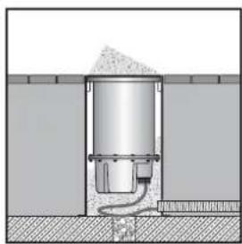
- With the fixture installed and clamped in place, fill the remaining space in the installation sleeve with oven-dried fine sand as described below. The sand must have a density of 1500-1600 kg/m3 (94-100 lb./cu.ft.) and grain size 0.18-0.5 mm (0.007-0.020 in.). One installation sleeve will accept approximately 40 kg (88 lb.) of sand.

natural_image
Diagram of a mechanical or fluidic device with a bulb and pipe, no visible text or symbols- Put the plate supplied with the installation sleeve on the Inground 200. Rotate the plate so that sand can run through the three cutouts into the bottom of the sleeve.

natural_image
Cross-sectional diagram of a cylindrical device with granular top and internal components, no text or symbols present- Tip sand onto the plate and guide it down between the cutouts in the plate and into the sleeve.
natural_image
Cross-sectional diagram of a mechanical or hydraulic system with no visible text or symbols- Fill as much sand as possible into the sleeve, packing it as tightly as possible. When the sleeve appears full, pour water into it to help the sand settle. Add sand as necessary.

natural_image
Cross-sectional diagram of a mechanical or electrical component with no visible text or symbols- Remove remaining sand from the plate with a vacuum cleaner and remove the plate. Remove any sand from inside the fixture and from the top glass sealing surface, and ensure there is clearance for the trim ring around the top of the fixture.
Use only sand of the specified type as fill material, or the fixture may tend to overheat.
The Inground 200 is now ready for internal components to be installed as described in the Installation Guide and product manuals.
Dimensions
Height 600mm (23.6 in.)
External diameter of tube 330mm (13 in.)
Base flange diameter 410mm (16.2 in.)
Construction
Acid-resistant stainless steel
Weight-bearing capacity
Installation sleeve with suitable groundwork 5000 kg (11,000 lb.)
Thermal
Max. recommended ambient temperature (Ta) 25°C (77°F)
Included items
Instruction note P/N 35000566
Clamp set (3 x 5mm M6 Allen hex cap clamp bolts, 3 x clamp blocks, 3 x 10mm M6 self-locking nuts)
Sleeve fill guide/cover plate
Accessories
Oven-dried fine beach sand, 25 kg (55 lb.) bag P/N 91611237
Ordering information
Installation sleeve, bevelled mount P/N 91611194
Installation sleeve, flush mount P/N 91611215
- Inground 200 TM
- Installation Guide
- IMPORTANT!
- Dimensions
- Contents
- Introduction ....5
- Safety precautions ...... 6
- Installation precautions....8
- Physical installation....11
- Cable Installation....14
- Powering on and commissioning ..... 18
- Installation troubleshooting....22
- Installation specifications....23
- Inground 200 TM installation sleeve instruction note....24
- Introduction
- Included items
- Overview of installation procedure
- Pre-installation
- Installation
- Exploded view
- Safety precautions
- Eliminating fire risk
- Protecting the public
- Installation precautions
- Avoiding corrosion
- Cooling
- Water resistance and drainage
- Avoiding condensation and humidity
- Clearing excess humidity
- Stability and weight-bearing capacity
- Disturbance by roots
- Service access
- Physical installation
- Safety
- Installation options
- Direct burial
- Direct burial: examples
- Installation sleeve
- Important! The installation sleeve is not recommended in locations where the ambient temperature exceeds 25° C ( 77° F).
- Sleeve installation: example
- Temporary installation sleeve cover
- Outdoor/ indoor installation
- Cable Installation
- Cable slack.
- Power cables and connections
- Power settings
- Connecting power cables
- EU models (230 V, 50 Hz models) mains power connections
- US models (210 V, 60 Hz and 277 V, 60 Hz models) mains power connections
- Control data cables and connections (Inground 200 CMY only)
- Control cable type and connector pinout
- XLR connection
- RJ-45 connection
- Control cable layout
- Connecting control data cables (Inground 200 CMY only)
- Powering on and commissioning
- Inground 200 CMY test sequence
- Test sequence scenes
- Beam adjustment
- Anti-humidity sachets
- Commissioning procedure
- Installation troubleshooting
- Installation specifications
- Weight-bearing capacity
- Connections
- Related items
- Ordering information
- Inground 200 TM installation sleeve instruction note
- Installing the sleeve
- Construction
- Thermal
- Accessories
Brand : MARTIN
Model : Inground 200 Single Color
Category : Outdoor Lighting