
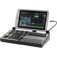
MaxModule Programmer - Audio mixer MARTIN - Free user manual and instructions
Find the device manual for free MaxModule Programmer MARTIN in PDF.


| Product Type | Lighting Control Module (Programmer) |
| Brand | Martin Professional |
| Model | MaxModule Programmer (P/N 90732150) |
| Dimensions (Length x Width x Height) | 275 mm x 483 mm x 128 mm |
| Weight | 5.0 kg (11.3 lbs) |
| Power Supply | 100-240 V nominal, 50/60 Hz, full range switch-mode |
| Main Fuses | 2 AT (slow blow) x2 |
| AC Power Throughput | Unswitched, unfused, max. 6 A |
| DMX Outputs | 2 x DMX (RDM-ready) via 5-pin locking XLR |
| Network Connections | WING IN (USB/RJ-45), WING OUT (Neutrik RJ-45 EtherCon), USB device socket, ADDR rotary dipswitch |
| Lamp Output | 12 V PWM via 2.5 mm DC bayonet socket |
| Controls | 4 x digital fader belts for fixture parameter control, trackball with pan/tilt control switch, blind/preview button, customizable highlight/lowlight function, next/last fixtures/groups, left/right mouse button, customizable LCD function keys |
| Compatibility | Requires Maxxyz controller running software version 2.6 or higher |
| Maximum Daisy-Chain Depth | 4 modules deep |
| Maximum Modules per Controller | 16 modules (8 fully populated frames) |
| ID Configuration | Rotary DIP switch (0 to F) |
| Included Items | MaxModule Programmer, two 2 AT fuses installed, IEC power cable (P/N 11501012), EtherCon network cable (P/N 11840144), USB cable (P/N 11840066), user manual |
| Safety | Professional use only; ground connection required; avoid rain/moisture; max ambient temp 40°C; do not block airflow |
| Cleaning | Periodic cleaning with lint-free cloth; do not spray cleaner directly on module |
| Service | Any service not described in manual must be carried out by qualified Martin technician |
Frequently Asked Questions - MaxModule Programmer MARTIN
User questions about MaxModule Programmer MARTIN
0 question about this device. Answer the ones you know or ask your own.
Ask a new question about this device
Download the instructions for your Audio mixer in PDF format for free! Find your manual MaxModule Programmer - MARTIN and take your electronic device back in hand. On this page are published all the documents necessary for the use of your device. MaxModule Programmer by MARTIN.
USER MANUAL MaxModule Programmer MARTIN
natural_image
Product display of multiple audio equipment modules including Plaptoch, Cerebrum, Bottom, Programmer, Schmaster, and a control panel with no visible text or symbols.MAXXYZ™ MODULES USER MANUAL
Martin
Dimensions
All dimensions are in millimeters
Maxxyz Cerebrum Module

natural_image
Technical illustration of a device with labeled dimensions (430 units), no readable text or symbols beyond the dimension label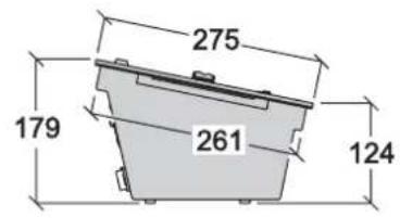

©2009 Martin Professional A/S. Information subject to change without notice. Martin Professional A/S and all affiliated companies disclaim liability for any injury, damage, direct or indirect loss, consequential or economic loss or any other loss occasioned by the use of, inability to use or reliance on the information contained in this manual. The Martin logo, the Martin name and all other trademarks in this document pertaining to services or products by Martin Professional A/S or its affiliates and subsidiaries are trademarks owned or licensed by Martin Professional A/S or its affiliates or subsidiaries.
P/N 35000223, Rev. B
Maxxyz Button, Playback, Programmer, Submaster Modules

Maxxyz Frame
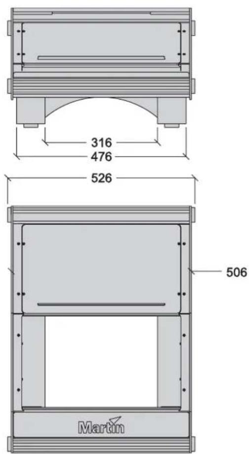

Table of Contents
1. Introduction......5
1.1 Technical support .... 5
1.2 Safety information....5
1.3 Connecting to power....6
1.4 Included items 6
2. Setup and Assembly 7
2.1 Single 'stand-alone' Maxxyz Module 7
2.2 Mounting in a Maxxyz Module Frame....7
Installing a module in the lower opening of the Frame 7
Installing a module in the upper opening of the Frame....9
2.3 Notes 12
3. Daisy-chaining modules 13
4. Connections and configuration....14
4.1 Cerebrum Module connections panel....14
4.2 Programmer, Submaster, Playback, Button connections panel 15
4.3 Connections....16
4.4 Configuration 16
4.5 Software 16
4.6 Controls 16
5. Service 17
5.1 Cleaning 17
6. Specifications....18
1. Introduction
Thank you for selecting a product from the Martin Professional™ Maxxyz™ Modules range.
The Maxxyz Modules are an extension to the Maxxyz ^TM controller, the Maxxyz Compact ^TM controller or the Maxxyz PC ^TM family.
The Maxxyz Modules concept consists of either one or two modules installed in one Module Frame.
This manual matches the functionality in Version 2.6 of the Maxxyz software. For the latest firmware and software updates, documentation and other information about this controller, see www.maxxyz.com
1.1 Technical support
For a complete list of Technical Support phone numbers, see the Martin website at http://www.martin.com/service/hotline.asp
1.2 Safety information
This product is for professional use only. It is not for household use. It presents risks of lethal or severe injury due to electric shock. Read this user manual before powering or installing the Modules, follow the safety precautions listed below and observe all warnings in this manual and printed on the product
If you have questions about how to operate the product safely, please contact your Martin supplier or call the Martin 24-hour service hotline on +45 8740 0000, or in the USA on 1-888-tech-180.
- Connect the product electrically to ground (earth).
- Use only a source of AC power that complies with local building and electrical codes and has both overload and ground-fault protection.
- Replace fuses with ones of the same type and rating only. Never attempt to bypass a fuse.
- Disconnect the product from power immediately if the power cable or any cover or component is wet or not in perfect condition. Do not reconnect to power until the damaged item has been repaired or replaced.
- Do not expose the product to rain or moisture.
- Allow free unobstructed airflow to the front and the back of the product.
- Do not use the product if the ambient temperature exceeds 40^ (104° F)
• Refer any service operation not described in this manual to a qualified technician. - Do not modify the product or install other than genuine Martin parts.
- Before transportation, secure modules in place in a frame with the supplied screws.
1.3 Connecting to power
Maxxyz Modules automatically adapt to AC mains power at 100-240 V nominal, 50/60 Hz. Do not connect them to power outside this range.
You may need to install a cord cap that fits your supply on the power cable. A 3-prong grounding-type plug must be installed following the plug manufacturer's instructions. The table below shows some possible pin identification schemes; if the pins are not clearly identified, or if you have any doubts about proper installation, consult a qualified electrician.
| Wire color (standard EU code) Pin Symbol | ||
| brown | live | |
| blue | neutral | |
| yellow/green | ground | |
L N
1.4 Included items
Each Maxxyz Module, part numbers 90732140 (Cerebrum), 90732150 (Programmer), 90732160 (Button), 90732170 (Submaster) and 90732180 (Playback), contains the following items:
- Maxxyz Module
- Two 2 AT fuses, installed
• IEC Power cable (part number 11501012) - Ethercon Network cable (part number 11840144)
• USB cable (part number 11840066) - User manual (part number 35000223)
Each Module Frame, part number 90732120 (shipped in flightcase) and 90732130 (shipped in cardboard box) contains the following items:
- Module Frame with attached Ethercon Power interconnect cables and desklight cable
- Desk lamp (built in)
- Blind cover plate (installed)
- Dust cover
2. Setup and Assembly
There are two different methods of setting up the Maxxyz Modules: one for "stand-alone" use and one for mounting in a Maxxyz Module Frame.
2.1 Single 'stand-alone' Maxxyz Module
Each module is shipped with protective foam attached to each side. This foam supports the faceplate and prevents cosmetic damage to the module. Apart from connection to the controller, the module is “ready to use” as soon as it is removed from its packaging.
2.2 Mounting in a Maxxyz Module Frame
Installing a module in the lower opening of the Frame
-
Remove the module(s) and the module frame from their packing material.
-
Use a 3 mm Allen wrench to remove the two screws that attach the side strips to each side of the module opening in the frame.

natural_image
Technical line drawing of a mechanical assembly with no visible text or symbols- The module can now be placed in the lower opening. Put the side strips back on each side of the module and fasten them in place with their screws.

natural_image
Technical line drawing of a server rack with ventilation grilles and cooling fans (no text or symbols)
Important! The Cerebrum Module only fits in the upper opening of the Maxxyz Module Frame.

-
Connect the Power interconnect cable to the MAINS IN connector, or, if only one module is used, connect the IEC Power cable (part number 11501012) to the MAINS IN connector.
-
Connect the EtherCon interconnect cable to the WING IN connector, or, if only one module is used, connect the EtherCon Network cable (part number 11840144) to the WING IN connector.
- Connect the Lamp bayonet plug to the "LAMP" connector. This will connect the top illumination to the module.
Installing a module in the upper opening of the Frame
Cerebrum module
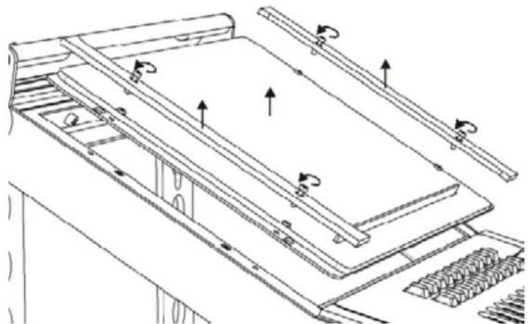
- Use a 3 mm Allen wrench to remove the four screws that attach the blind cover plate (if installed) to the frame.
natural_image
Technical line drawing of a mechanical assembly with rotating components (no text or symbols)- The Cerebrum Module can now be placed into the top opening. Put the side strips back on each side of the frame and fasten them in place with their screws.

natural_image
Technical line drawing of a mechanical assembly with no visible text or symbols
- Connect the Power interconnect cable to the MAINS OUT connector.
- Connect the EtherCon Network cable (part number 11840144) to the WING OUT connector.
- Connect the IEC Power cable (part number 11501012) to the MAINS IN connector.

Important! The Cerebrum Module is a controller module and must not be connected to a Maxxyz controller, a Maxxyz Compact controller, a Maxxyz PC or another Cerebrum using the WING OUT outputs. The WING OUT outputs must only used to connect non-controller modules (Programmer, Button, Submaster and Playback Modules) to the Cerebrum.
Non-controller modules (i.e. not Cerebrum module)
- Use a 3mm Allen wrench to remove the four screws that attach the blind cover plate (if installed) to the frame.

natural_image
Technical line drawing of a mechanical assembly with rotating components (no text or symbols)- The module can now be placed in the top opening. Put the side strips back on each side of the frame and fasten them in place with their screws.

natural_image
Technical line drawing of a mechanical assembly with multiple components and directional arrows (no text or symbols)
- Connect the Power interconnect cable to the MAINS OUT connector.
- Connect the EtherCon Network cable (part number 11840144) to the WING OUT connector.
- Connect the IEC Power cable (part number 11501012) to the MAINS IN connector.
- Connect the EtherCon Network cable (part number 11840144) to the WING IN connector.
2.3 Notes
If the top module is not powered, the bottom module will not be able to communicate with the controller it is connected to.
The power switch is hidden behind the leg (if you stand in front of the controller, the switch can be found on the left-hand side).
The modules (but NOT the Cerebrum module, part number 90732140) can also be connected directly to a laptop or PC using a USB cable.
A non-controller module means a Playback, Submaster, Programmer or Button module.
A controller module means a Cerebrum module or a Wing OUT connection of a non-controller module, but can also be a Maxxyz, Maxxyz Compact or Maxxyz PC.

Important! Do not use both WING IN connections, USB and XLR, at the same time.
The modules can also be used in combination with older playback modules. The older modules, however, do not fit in the new frame.
3. Daisy-chaining modules
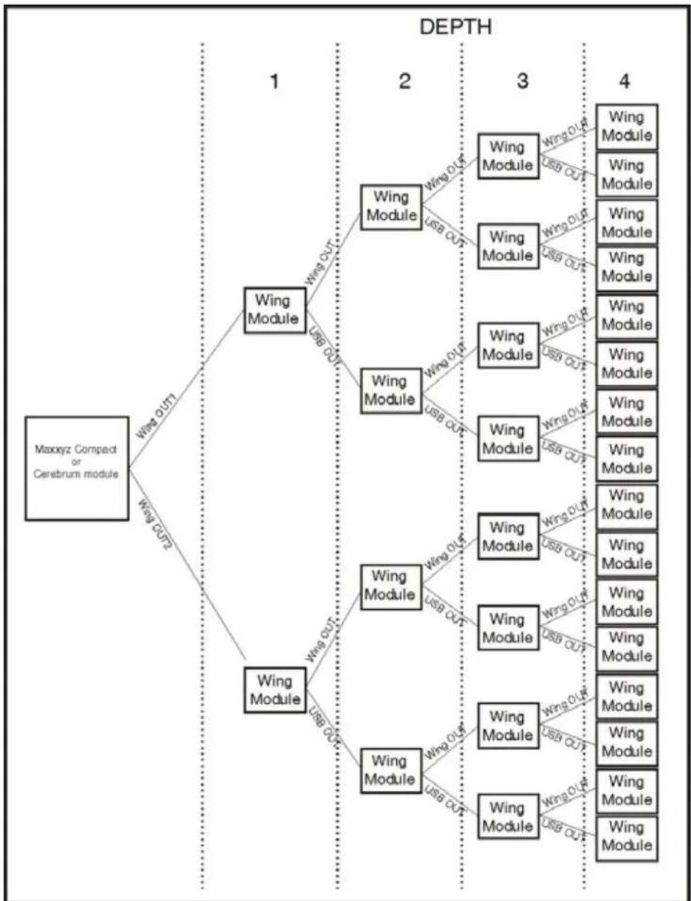
Modules can be daisy-chained to a maximum of 4 modules deep. Each module has 2 outputs to daisy-chain to the next module(s): the Wing out and USB connections. Each Maxxyz Wing module uses some USB bandwidth (the amount depends on the Wing type being used), therefore it is possible that some modules will not be recognized if too many Wing modules are connected to a controller module.
Do not daisy-chain more than 4 modules deep. If the setup is 5 modules deep, the fifth module will not be recognized.
flowchart
graph TD
    A["Maxxyz Compact or Cerebrum module"] -->|Wing OUT| B["Wing Module"]
    A -->|Wing OUT| C["Wing Module"]
    B -->|Wing OUT| D["Wing Module"]
    B -->|Wing OUT| E["Wing Module"]
    C -->|Wing OUT| F["Wing Module"]
    C -->|Wing OUT| G["Wing Module"]
    D -->|Wing OUT| H["Wing Module"]
    D -->|Wing OUT| I["Wing Module"]
    E -->|Wing OUT| J["Wing Module"]
    E -->|Wing OUT| K["Wing Module"]
    F -->|Wing OUT| L["Wing Module"]
    F -->|Wing OUT| M["Wing Module"]
    G -->|Wing OUT| N["Wing Module"]
    G -->|Wing OUT| O["Wing Module"]
    H -->|Wing OUT| P["Wing Module"]
    H -->|Wing OUT| Q["Wing Module"]
    I -->|Wing OUT| R["Wing Module"]
    I -->|Wing OUT| S["Wing Module"]
    J -->|Wing OUT| T["Wing Module"]
    J -->|Wing OUT| U["Wing Module"]
    K -->|Wing OUT| V["Wing Module"]
    K -->|Wing OUT| W["Wing Module"]
    L -->|Wing OUT| X["Wing Module"]
    L -->|Wing OUT| Y["Wing Module"]
    M -->|Wing OUT| Z["Wing Module"]
    M -->|Wing OUT| AA["Wing Module"]
    N -->|Wing OUT| AB["Wing Module"]
    N -->|Wing OUT| AC["Wing Module"]
    O -->|Wing OUT| AD["Wing Module"]
    O -->|Wing OUT| AE["Wing Module"]
    P -->|Wing OUT| AF["Wing Module"]
    P -->|Wing OUT| AG["Wing Module"]
    Q -->|Wing OUT| AH["Wing Module"]
    Q -->|Wing OUT| AI["Wing Module"]
    R -->|Wing OUT| AJ["Wing Module"]
    R -->|Wing OUT| AK["Wing Module"]
    S -->|Wing OUT| AL["Wing Module"]
    S -->|Wing OUT| AM["Wing Module"]
    T -->|Wing OUT| AN["Wing Module"]
    T -->|Wing OUT| AO["Wing Module"]
    U -->|Wing OUT| AP["Wing Module"]
    U -->|Wing OUT| AQ["Wing Module"]
    V -->|Wing OUT| AR["Wing Module"]
    V -->|Wing OUT| AS["Wing Module"]
    W -->|Wing OUT| AT["Wing Module"]
    W -->|Wing OUT| AU["Wing Module"]
    X -->|Wing OUT| AV["Wing Module"]
    X -->|Wing OUT| AW["Wing Module"]
    Y -->|Wing OUT| AX["Wing Module"]
    Y -->|Wing OUT| AY["Wing Module"]
4. Connections and configuration
4.1 Cerebrum Module connections panel

RESET Use a ballpoint pen or pencil to press this switch. Activating the switch causes a hardware reset.
POWER ON Use a ballpoint pen or pencil to press this switch. Activating the switch is needed if the module refuses to start when power is applied to the module and the Power Switch is set to ON
EtherDMX Artnet-compatible network XLR
USB USB device socket
External VGA External monitor connector
DMX A, DMX B DMX outputs (RDM-ready)
WING OUT 1, Wing output RJ45 in XLR-type housing. Important! Connect only other non-controller modules (Programmer, Submaster, Playback or Button Modules) to these outputs. Never use this output to connect to a Maxxyz, Maxxyz Compact, Maxxyz PC or another Cerebrum module.
MIC Audio microphone input
Line input Stereo line-level audio inputs, left and right
Line output Stereo line-level audio outputs, left and right
REMOTE MaxNet controller network RJ45 in XLR-type housing
NETWORK
IEC OUT AC output, unswitched, unfused. Warning! Do not draw a current of more than 6 A total from this output
IEC IN AC mains power input, accepts 100-240 V nominal, 50/60 Hz
FUSE Fuse holder, two 2 AT (slow blow) fuses
Power Switch Power on/off
4.2 Programmer, Submaster, Playback, Button connections panel

WING OUT Wing output RJ45 in XLR-type housing. Important! Connect only other non-controller modules (Programmer, Submaster, Playback or Button Modules) to this output. Never use this output to connect to a Maxxyz, Maxxyz Compact, Maxxyz PC or Cerebrum module.
USB USB device socket
LAMP 12 V PWM controlled lamp output
ADDR Rotary dipswitch, 0 to F selectable
WING IN Wing input (USB and RJ45 in XLR-type housing). Use only one of these sockets at any one time to connect the module to a Maxxyz controller, Maxxyz Compact controller, Cerebrum module or Maxxyz PC. Important! Never use the USB and RJ45 sockets at the same time.
DMX A, DMX B DMX outputs (RD-ready)
IEC OUT AC output, unswitched, unfused. Warning! Do not draw a current of more than 6 A total from this output
IEC IN AC mains power input, accepts 100-240 V nominal, 50/60 Hz
FUSE Fuse holder, two 2 AT (slow blow) fuses
Power Switch Power on/off
4.3 Connections
Connections to a Maxxyz controller, a Maxxyz Compact controller or a Maxxyz PC for either an individual Maxxyz Module or a frame with modules are similar.
- Connect an EtherCon Network cable (part number 11840144) to the "WING IN" connector on the back of the module. If you are using the frame, use the "WING IN" connector on the top module.

Important! Never use a WING OUT connection to connect a module to a Maxxyz controller, a Maxxyz Compact controller, a Maxxyz PC or a Cerebrum module.
- Connect the other end of the EtherCon Network cable (part number 11840144) to either "WING 1", "WING 2", "WING 3" or "WING 4" connector on the back of the Maxxyz controller or the Maxxyz Compact controller. It doesn't matter which connector you use.
- Connect the IEC Power cable (part number 11501012) to the “MAINS IN” connector on the back of the module and plug the other end of the IEC Power cable (part number 11501012) to your mains power supply. If you are using the frame, use the “MAINS IN” on the top module (if installed).
While it is possible to use the frame standing separately from the Maxxyz controller, Maxxyz Compact controller or the Maxxyz PC controller, it is also possible to connect the frame directly to any of these devices.
4.4 Configuration
It is possible to connect up to sixteen (16) modules (or eight fully populated Maxxyz Module Frames) to a Maxxyz controller, a Maxxyz Compact controller or a Maxxyz PC controller. No more than four modules may be connected to any given "WING" connector found on the back of the controller and every module must have a unique ID (0, 1, 2, 3, 4, 5, 6, 7, 8, 9, A, B, C, D, E, F). These IDs are set using the rotary DIP switch found on the back of the module.
4.5 Software
The modules require connection to a Maxxyz controller running Version 2.6 or higher.
4.6 Controls
Most of the functionality of the Maxxyz Modules is covered in the Martin Maxxyz User Manual.
5. Service
The Maxxyz Modules are designed as rugged, roadworthy devices. Occasional cleaning is the only service required of the user. For any other service-related concerns, please contact your Martin dealer or visit www.martin.com.
Any service not described in this User Manual must be carried out by a qualified Martin technician.
5.1 Cleaning
The Maxxyz Modules require periodic cleaning, as does any computer. The schedule depends heavily on the operating environment; please consult a Martin service technician for recommendations if needed.
As with any computer, never spray the cleaner directly onto the module, always spray onto a lint-free cloth and wipe clean.

Important! Excessive dust and smoke fluid build-up can degrade performance and cause overheating and damage to the module that is not covered by the warranty.
6. Specifications
Physical
Cerebrum Module
Length 275 mm (10.9 in.)
Width 483 mm (19 in.)
Height....182 mm (7.2 in.)
Weight 7.3 kg (16.1 lbs.)
Playback Module
Length 275 mm (10.9 in.)
Width 483 mm (19 in.)
Height....128 mm (5 in.)
Weight 5.7 kg (12.6 lbs.)
Submaster Module
Length 275 mm (10.9 in.)
Width 483 mm (19 in.)
Height....128 mm (5 in.)
Weight 4.6 kg (10.2 lbs.)
Button Module
Length 275 mm (10.9 in.)
Width 483 mm (19 in.)
Height 128 mm (5 in.)
Weight 5.2 kg (11.5 lbs.)
Programmer Module
Length 275 mm (10.9 in.)
Width 483 mm (19 in.)
Height....128 mm (5 in.)
Weight 5.0 kg (11.3 lbs.)
Frame without modules
Length 695 mm (27.3 in.)
Width 526 mm (20.7 in.)
Height....336 mm (13.21 in.)
Weight 10.3 kg (22.7 lbs.)
Connections
Cerebrum Module
AC Power input ....3-pin IEC male socket
AC Power output ....3-pin IEC female socket
LINK USB data outputs .... Neutrik RJ-45 socket (accepts Neutrik ...EtherCon connectors in housing)
Network data.... Neutrik RJ-45 socket (accepts Neutrik ...EtherCon connectors in housing)
EtherDMX data .... Neutrik RJ-45 socket (accepts Neutrik ...EtherCon connectors in housing)
DMX data....5-pin locking XLR
USB devices ....USB host socket
Microphone 6.3 mm mono socket
Audio in/out....RCA phono
VGA 15-pin D-sub female
Other modules (not Cerebrum)
AC Power input.....I.E.C. male socket
AC Power output....I.E.C. female socket
LINK USB data output...... Neutrik RJ-45 socket (accepts Neutrik ...EtherCon connectors in housing)
LINK USB data input....Neutrik RJ-45 socket (accepts Neutrik ...EtherCon connectors in housing)
DMX data....5-pin locking XLR
USB devices ....USB host socket
USB input....USB device socket
Lamp output....2.5 mm DC bayonet socket ....(also accepts 2.5 mm DC plugs without bayonet)
Electrical (all modules)
AC power 100-240 V nominal, 50/60 Hz
Power supply unit.... Full range switch-mode
Main fuses.... 2 AT (x2)
AC power throughput.... unswitched, unfused, Max. 6 A
Lamp output (not on Cerebrum).... 12 V PWM
Functional
Cerebrum Module
- Grand master fader and button
- Flash master fader and button
- 16 x view buttons, 2 x view scroll buttons
• Digital encoder wheels for window scrolling and screen/desk lamp intensity - Protocol: DMX512, Artnet (ACN and RDM pending)
• 2 DMX universes, expandable to 32
• 1024 channels, expandable to 16384 - No limit to number of DMX channels per fixture
- Extensive fixture library for all known manufacturers
- 65000 presets for each group of functions (P/T, color, gobo, etc.)
• Effect generator for automated programming of complex effects - Customizable highlight and lowlight function to identify individual fixtures
• Relative or absolute programming
• Fan function for all channels (including timing parameters) -
On-the-fly global timing changes
-
Virtual cuelists
- Macros
- Wait, follow and link cues
- HTP, LTP, chase, timecode, submaster and group master playback functionality
- Individual parameter timings
- Intuitive patch feature
- Fixture type cloning
• Full 16-bit fading for high-resolution fixtures - Individual fade in/fade out times for all playbacks
- Manual override available at all times
• Live 0-1000% override of global cue timings
• Live programmer timing ("Sneak") - Go-function (supports multiple cues simultaneously)
- Cuelists can be executed in tracking or non-tracking mode
Playback Module
- 10 x motorized playback faders, each with one dynamically labeled LCD button (to identify/activate playback) and two function-assignable buttons
- 10 x pause/back buttons
- 10 x go buttons
- 10 x flash buttons
- 5 x LCD navigation buttons with scroll wheel
- Master GO section
Submaster Module
- 24 x non-motorized faders with single function button (every supported cue list type is supported)
• 40-character display for labeling - 5 x LCD navigation buttons with scroll wheel
Button Module
- 3 rows of 10 × LCD and function button combination
- 5 x LCD navigation buttons with scroll wheel
• Digital fader belt for intensity, speed and timing controls - Mode buttons for selecting desired operation per row. Supported modes are:
- Fixture Selection
- Group Selection
- Preset Selection
- Playback Buttons
Programmer Module
• 4 x digital fader belts for fixture parameter control
- Trackball with pan/tilt control switch
- Blind/preview button
- Customizable highlight/lowlight function
- Next/last fixtures/groups
- Left/right mouse button
- Customizable LCD function keys for function shortcuts
Frame without modules
- Blind cover plate with paper holder
- Accepts two Maxxyz Modules (Cerebrum can be installed in upper position only)
- Dimmable LED strip (requires Module to be installed)
Accessories
Blind cover plate for Maxxyz Frame Module.... P/N 62406159
Maxxyz Modules dust cover P/N 33302009
Maxxyz Compact monitor bracket, left.... P/N 55732076
Maxxyz Compact monitor bracket, right.... P/N 55732074
Four 3-pin female to 5-pin male XLR adapters.... P/N 91613024
1.5 m power cable, 3-pin IEC.... P/N 11501012
EtherCon patch cable, 2 m, RJ-45 in XLR-type housing..... P/N 11840144
Flightcase for Maxxyz Modules Frame P/N 91535007
Wheel set for Maxxyz Modules flight case.... Contact Martin for details
Ordering Information
MaxModule Cerebrum P/N 90732140
MaxModule Button.... P/N 90732160
MaxModule Playback.... P/N 90732180
MaxModule Programmer P/N 90732150
MaxModule Submaster.... P/N 90732170
MaxModule Frame (empty) in Flightcase.... P/N 90732120
MaxModule Frame (empty) in Cardboard Box.... P/N 90732130
Specifications subject to change without notice.
See www.martin.com for current user documentation, technical support and full current product specifications.


- MAXXYZ™ MODULES USER MANUAL
- Martin
- Dimensions
- Table of Contents
- Introduction......5
- Setup and Assembly 7
- Daisy-chaining modules 13
- Connections and configuration....14
- Service 17
- Specifications....18
- Introduction
- Technical support
- Safety information
- Connecting to power
- Included items
- Setup and Assembly
- Single 'stand-alone' Maxxyz Module
- Mounting in a Maxxyz Module Frame
- Installing a module in the lower opening of the Frame
- Installing a module in the upper opening of the Frame
- Cerebrum module
- Non-controller modules (i.e. not Cerebrum module)
- Notes
- Daisy-chaining modules
- Connections and configuration
- Cerebrum Module connections panel
- Programmer, Submaster, Playback, Button connections panel
- Connections
- Configuration
- Software
- Controls
- Service
- Cleaning
- Specifications
- Physical
- Playback Module
- Submaster Module
- Button Module
- Programmer Module
- Frame without modules
- Connections
- Other modules (not Cerebrum)
- Electrical (all modules)
- Functional
- Accessories
- Ordering Information
Brand : MARTIN
Model : MaxModule Programmer
Category : Audio mixer