
R21509 - Home Automation Vimar - Free user manual and instructions
Find the device manual for free R21509 Vimar in PDF.


| Product Type | Home Automation Module |
| Brand | Vimar |
| Model | R21509 |
| Dimensions | 75 x 50 x 30 mm |
| Weight | 100 g |
| Power Supply | 24 V DC |
| Operating Temperature | 0°C to 40°C |
| Installation | DIN rail mount |
| Connectivity | Vimar by-me BUS system |
| Main Functions | Control lighting, blinds, heating; supports scenes and timers |
| Compatibility | Works with Vimar home automation systems |
| LED Indicators | Status LED for power and communication |
| Protection Rating | IP20 |
| Materials | Flame-retardant plastic |
| Maintenance | Clean with dry cloth; avoid solvents |
| Safety Certifications | CE, RoHS |
| Spare Parts | Not available separately; replace unit |
| Repairability | Non-repairable; replace if defective |
Frequently Asked Questions - R21509 Vimar
User questions about R21509 Vimar
0 question about this device. Answer the ones you know or ask your own.
Ask a new question about this device
Download the instructions for your Home Automation in PDF format for free! Find your manual R21509 - Vimar and take your electronic device back in hand. On this page are published all the documents necessary for the use of your device. R21509 by Vimar.
USER MANUAL R21509 Vimar
Section Automation 3
Section Home automation control equipment 77
Section Speaker system 93
Section Light Control 155
Section Power management 173
Section Tactil Devices....195
Section Temperature control 201
Section Plug&Play 267
Section
Automation
Table of Contents
General information....6
- Main functions 7
- Basic concepts.... 8
- Installation topology.... 14
3.1 Installation of bus systems.... 15
3.2 Description of terminals 18
3.3 Putting the system into service 19
- Main configurations 20
4.1 Navigating the control unit menus 20
4.2 Initial switch-on 21
4.3 Main screens of the control unit 23
4.4 Settings menu.... 24
4.5 Configuration menu.... 29
- Scenarios 58
5.1 Creating a scenario 58
5.2 Activating a scenario 60
5.3 Renaming a scenario....60
5.4 Cancelling a button associated with the scenario.... 61
5.5 Modifying groups associated with a scenario 61
5.6 Saving a scenario 61
5.7 Remote activation of a scenario.... 61
5.8 Deleting a scenario 61
- Programming events 62
6.1 Programming.... 62
6.2 Operation 68
6.3 Example applications.... 69
- Integration of the presence detectors.... 73
- Diagnostics and maintenance 74
8.1 Diagnostics and replacement of devices 74
8.2 Remote communications management 75
8.3 Control unit software release 75
-
Installation rules 76
-
Compliance with regulations 76
- Supplementary declarations made by the manufacturer 76
General information
The By-me automated system via the control unit 21509 provides integrated control of comfort, security, energy saving, HVAC and remote control in the residential and commercial sectors.
This manual is arranged in a sequence of sections that provide a complete understanding of the By-me system and allow the user to take full advantage of the available features:
- Chapter 1 "Main functions": describes what can be controlled with the By-me system (see page 7);
- Chapter 2 "Basic concepts": explains some basic concepts necessary for gaining an understanding the By-me system (see page 8);
- Chapter 3 “Installation topology”: describes the structure of the By-me system and gives the general rules and information necessary for setting the system structure and the information necessary for putting into operation (see page 14);
- Chapter 4 "Main configurations": describes the configuration procedures and main settings of the By-me system (see page 20);
- Chapter 5 "Scenarios": describes the procedures for creating scenarios where a number of functions are actuated at the same time (see page 58);
- Chapter 6 "Programming events": describes the procedures for advanced management of the By-me system, in order to be able to initiate functions that perform special operations when certain events occur (see page 62);
- Chapter 7 "Integration of the passive infrared presence detector": describes the procedures for managing the detectors when used as presence sensors for lighting control (see page 73).
- Chapter 8 “Diagnostics and maintenance”: describes the procedures for monitoring the operation of devices and managing their replacement where necessary (see page 74).
Main functions:
1. Main functions.
The By-me system makes it possible to manage the installation using the following controls:
- Ambient temperature management, dividing the installation into up to 40 areas controlled by 40 separate programs;
• Lighting management, with on/off control and light adjustment;
• Control for roller shutters and blinds; - Function centralization and automation (up to 32 scenarios and 16 programs);
- Remote control and monitoring of functions;
• Power consumption and load control. - Speaker system management.
Using the Web Server (art. 01945-01946), you can interface the By-me system with the By-alarm intrusion detection system for a fully integrated home automation system.

flowchart
graph TD
    A["Main menu"] --> B["Scenarios"]
    A --> C["Events Programme"]
    A --> D["Climate"]
    A --> E["Temperature Probe"]
    A --> F["Logout Setup"]
    G["SAVINGS"] --> H["Power management"]
    G --> I["Load programming"]
    G --> J["Temperature control"]
    K["REMOTE CONTROL"] --> L["Temperature status"]
    K --> M["Aircon programming"]
    K --> N["Alarm signals"]
    K --> O["Device actuation"]
    K --> P["Scenario activation"]
    K --> Q["Intrusion detection alarm system"]
    K --> R["ON/OFF"]
    K --> S["Diagnostics"]
    T["COMFORT SECURITY"] --> U["Scenarios"]
    T --> V["Light automation"]
    T --> W["Shutter automation"]
    T --> X["Temperature control"]
    T --> Y["Programmed actions"]
    T --> Z["Load control"]
    T --> AA["Speaker system"]
    AB["Technical alarms"] --> AC["Access control"]
    AB --> AD["emergency lighting"]
Control unit 21509
Basic concepts
2. Basic concepts.
This chapter explains some fundamentally important concepts that are necessary for correctly making full use of the system.
- Functional unit: part of a device that can be considered as if it were a separate device. Some examples:
- Appliance with one functional unit: the functional unit is equivalent to the device itself, for example actuator with change-over relay output 16 A 250 V\~ (Eikon 20535; Arké 19535, Idea 16975; Plana 14535 series).
- Appliance with two functional units: in the interface for conventional controls (Eikon 20515; Arké 19515, Idea 16955; Plana 14515) each of the two inputs is a functional unit.
- Appliance with three functional units: in the control equipment with two rocker switches and actuator there are three functional units: left rocker switch, right rocker switch and actuator that, from the point of view of the configuration and operation, are to all intents and purposes 3 different devices.
- Appliance with four functional units: in the control equipment with three rocker switches and actuator there are four functional units: left rocker switch, central rocker switch, right rocker switch and actuator that, from the point of view of the configuration and operation, are to all intents and purposes 4 different devices. Another example is the device with 4 changeover relays (art. 01851.2 for installation on DIN (60715 TH35) rails) where each output is a functional unit.
During the design phase, each functional unit of any device must be considered as though it were a separate device. It is therefore necessary, during the design phase, to plan the functions to be performed and only then make a list of the devices needed to perform these functions.
The next diagram opposite shows the ten functional units of a control device with six push buttons and the actuator art. 01486.

Basic concepts
For example, during installation, the actuator could be used to control load A through the push-button of another device, the left push-button to control load B through an actuator, the middle button to control load C through a second actuator and the right button to control load D through a third actuator.
Control appliance with six push buttons and actuator
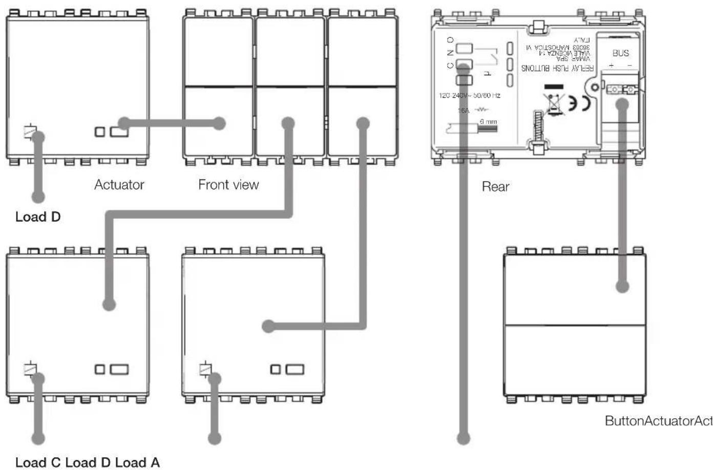
There are no limits on the use of the functional units of a physical device. When a load is to be controlled, it is necessary to provide one control device and one actuator connected to the load.
Basic concepts
- Connection: logic link between two functional units, which allows a function to be shared (for example: actuator relay and push button).
- Configuration: operation that can be used to create the logic connection between various functional units (of various appliances).
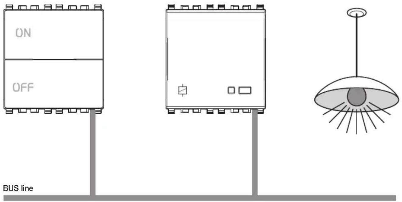
- Functional group (or Group): set of functional units connected logically with each other that provide a function in the system (for example: three different buttons that control a single actuator and, as a result, the same load). The devices that make up a functional group are connected to each other logically, not by conventional wiring.
Control equipment with four button. Actuator with relay output.
IMPORTANT:
Groups must comprise only functional units that are harmonious with each other: any one group cannot contain an actuator for roller shutters and an actuator to control the lighting of a lamp.
Basic concepts
To control the switching on of a load from different points, it is sufficient to add more functional units; it is not necessary to modify the wiring.

- Group depth: number of groups to which one functional unit can belong. Each functional unit can belong to a maximum of 4 different groups keeping the same function (for example “dimmer control”).

Group 1 = device 1: left button functional unit + device 1 actuator
Group 2 = device 2: left button functional unit + device 2 actuator
Group 3 = device 3: button functional unit + device 1 and 2 actuator functional unit
Actuators are of group depth 2 since they both belong to two groups.
Basic concepts
- Scenario: a scenario is an exact positioning of the actuators in one or more functional groups that can be called up as preferred from a menu on the control unit or with a button configured for this purpose or with the infrared remote control 01849. For example, the rolling shutters could be lowered and a lamp lit in the room at the same time. A scenario can also be activated with the programs that can be configured via the Events menu or remotely with the GSM communicator or Web Server.
- Parameters: these can be set at the control unit, and are used to modify and customize the operation of each functional unit. For example, the relay actuator (Eikon 20535, Arké 19535, Idea 16757; Plana 14535), during configuration, behaves as a two-position stable relay. It is, however, possible to configure it as one-position stable; in this case it is necessary to define the deactivation time too.
• Line: any set of devices. - Scenario depth: number of scenarios to which a group can belong. Each functional group can belong to a maximum of 4 different scenarios.
- Bus line: equipment used to carry the electrical or electromagnetic signals associated with the messages between the system devices.
- Bus system: set of devices and their interconnections creating applications by using a common communications framework.
- Command: functional unit that sends commands and/or statuses over the bus line.
- Actuator: functional unit that receives commands and/or statuses from the bus line in order to carry out a predetermined action.
The system in general is made up of three main families of functional unit:
- Controls (for example, push-buttons, sensors and infrared remote controls)
- Actuators (for example, relays and dimmers)
- Controllers (for example, the control unit)
Each line can be composed of at most 128 devices and needs one or two power supplies depending on the number of devices and the length of the bus.
Using line couplers, a number of lines can be connected to each other, up to a maximum of 15 areas by 15 lines; the line couplers allow only authorized messages to pass between one line and another.
On each By-me control unit it is possible to configure up to 254 devices.
System configuration starts with the creation of functional groups (it is better to think in terms of functional groups rather than individual devices), which is the only operation strictly necessary for the system to function. During the installation phase, the first operation is therefore to assume the functions that are to be made available.
Subsequent operations, such as placing a number of units together in one scenario or setting a number of automated functions, should be treated as a system customization or as the use of advanced functions.
Basic concepts
From the moment the groups are created, the control unit has no role in their operation; the devices and related functional groups are “connected” to each other and do not require any intervention by the control unit (the control unit is still needed, however, for managing editing functions, HVAC automation and automation programmes).
In the event of a power failure, when the mains power returns, the actuators will keep their status prior to the event. Following a Reset applied to an actuator, instead, the actuator will go back to opening the contact (applies both to relay actuators and roller shutter actuators).
Installation topology
3. Installation topology.
The main characteristic of the By-me system is that all devices are connected to each other by a bus system cable (pair) that supplies the devices with the power and the signals carrying the digital control and monitoring data.
WARNING:
On a line where a control unit 21509 has already been configured it is not possible to configure a second control unit.
The system is configured through the control unit and the configuration buttons located on the devices.
CONNECTION DIAGRAM with separation coupler from another automation line.

flowchart
graph TD
    A["Power supply Line 1"] -->|230 V~| B["Control Unit 21509"]
    B --> C["IR detector"]
    C --> D["Line coupler"]
    D --> E["Controls with relay actuator"]
    E --> F["Relay actuator"]
    E --> G["Controls with roller shade actuator"]
    E --> H["Controls with relay actuator"]
    B --> I["bus"]
    I --> J["Power supply Line 2"]
    J --> K["230 V~"]
    style A fill:#f9f,stroke:#333
    style B fill:#ccf,stroke:#333
    style C fill:#cfc,stroke:#333
    style D fill:#fcc,stroke:#333
    style E fill:#ffc,stroke:#333
    style F fill:#cff,stroke:#333
    style G fill:#ffc,stroke:#333
    style H fill:#ffc,stroke:#333
    style I fill:#cfc,stroke:#333
    style J fill:#fcc,stroke:#333
Installation topology
The power consumption of the control unit is:
-45 mA of maximum instantaneous consumption with backlit display;
-25 mA with display without backlighting (Stand By);
3.1 Bus system installation.
3.1.1 General rules and system topology.
- For the connections use the twisted pair and sheathed cable VIMAR 01840.E (2x0.5 mm², rated voltage to earth 400 V, suited for installation with Category I power cables). The wire pair distributes both the power supply voltage (29 V d.c.) and the device control signals, and can be placed inside the same corrugated pipe that carries the electrical mains cables.
- A bus line must be supplied by 1 or 2 power supplies 01401.
Each line can be controlled by a single control unit and can be composed of at most 128 devices and at most two power supplies, depending on the number of devices and the length of the connecting cable (pair).
- If a system is being installed with only one power supply and the number of devices is close to the maximum number allowed, it is advisable to plan for a second power supply to allow for future extensions of the system.
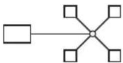
- The devices do not have to be connected in any particular order, maintaining the polarities indicated on the terminals. Linear type connections (figure 3.1.1.1), star type connections (figure 3.1.1.2) or mixed connections (figure 3.1.1.3) are possible (the rectangle in the figures represents the power supply). The ideal configuration is the linear type with only one power supply in the middle of the system, or two power supplies at the ends of the bus cable.
- The total current used by the various devices must not exceed the nominal current of the power supply (or supplies) installed.
- The voltage at all points on the bus, with all devices at rest, must never go below 23 V d.c. Check particularly the points furthest away from the power supply and the sections of cable where the load is highest.
- The voltage at all points on the bus, when the most numerous group of shutter actuators is in operation, must never go below 22 V d.c. (check the points furthest away from the power supply). The delayed actuation function can be useful for reducing the number of shutter actuators in operation at the same time.
- The By-me control unit can manage up to 20 different users (including the administrator), each one with their own privileges and password.
- The By-me control unit can manage up to at most 480 groups (automation, intrusion detection alarm system, loads, etc.).
Installation topology
3.1.1.1

flowchart
graph TD
    A[" "] --> B[" "]
    B --> C[" "]
    C --> D[" "]
    D --> E[" "]
    E --> F[" "]
3.1.1.3

flowchart
graph TD
    A["Parent"] --> B["Child 1"]
    A --> C["Child 2"]
    A --> D["Child 3"]
    A --> E["Child 4"]
    B --> F["Sub-Child 1"]
    C --> G["Sub-Child 2"]
    D --> H["Sub-Child 3"]
    E --> I["Sub-Child 4"]
    F --> J["Leaf 1"]
    G --> K["Leaf 2"]
    H --> L["Leaf 3"]
    I --> M["Leaf 4"]
3.1.1.2
- The By-me control unit is able to configure up to at most 254 devices divided over a number of lines (including the couplers 01845.1); each device can have from 1 to 4 functional units. Lastly, bear in mind that one line can be installed with up to at most 2 power supplies 01401 (which can sustain up to a maximum consumption of 1.6 A on the bus line).
- It is essential to protect the system from the effects of lighting using surge protection devices (SPD). As a general rule, the power supply side must be protected using a Class 1 SPD downstream of the power meter, a Class 2 SPD after the magneto-thermal protection device, and a Class 3 SPD at the power supply input. If a telephone communicator is present, it is advisable also to install an SPD on the telephone line.
3.1.2 System setup.
During the design phase, it is essential to arrange for a consumer unit with sufficient capacity to hold:
• conventional devices, magneto-thermal protections, circuit-breakers, etc;
- 1 or 2 power supplies with capacity for 9 modules on DIN (60715 TH35) rails;
• DIN (60715 TH35) rail devices such as the load control module, GSM communicator, interfaces, web server.
• surge protection devices to protect the installation.
As regards the corrugated pipes for laying the Vimar cable 01840.E of the BUS line, it is advisable to plan for a dedicated raceway; it is however possible to use those where the cables of the electric mains pass.
3.1.3 Bus length: general rules.
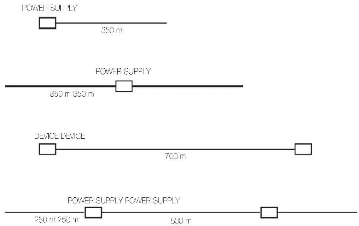
• Maximum distance between power supply and device: 350 m.
• Maximum distance between devices: 700 m.
• Maximum length of the bus cable: 1000 m.
- Minimum distance between 2 power supplies: 40 m. It is important for the load to be well distributed between the two power supplies.
Installation topology
• Essential requirements:
- the distance between two power supplies must never be less than 40m ;
- the load must be well distributed between the two power supplies;
- the two power supplies should be placed at the ends of the one of the circuits of the system that has the largest number of devices or branches.
In any case the optimal configuration has the power supplies set as far apart as possible; this has a positive effect also on the minimum voltage on the bus.
3.1.4 Length of the BUS line.
The following is a list of the maximum lengths of the BUS line installed in systems with the linear configuration (the rectangle in the figure represents the power supply).
Installation topology
3.1.5 Bus installation: summary table.
• Installation and system topology:
- Cable of the BUS line laid in dedicated raceways; it can also be laid in the corrugated pipes that contain the electric line.
-
Configurations allowed:
-
Linear configuration
- Star configuration
- Mixed configuration
• We recommend using junction boxes
- For the connections use the twisted pair and sheathed cable VIMAR 01840.E (2x0.5 mm², rated voltage to earth 400 V, suited for installation with Category I power cables)
• Devices and distances per line
- Logic capacity (number of addresses): 128
• Maximum distance between power supply and last device: 350 m
• Maximum total length of the bus line: 1,000 m
• Maximum distance between two devices: 700 m - Minimum distance between two power supplies: 40 m (loads must be balanced between the two power supplies)
- Optimal position for each single power supply: in the centre of the BUS line
- Optimal position for two power supplies: at the ends of the BUS line
• Minimum voltage on the furthest device: 23 V d.c. (at rest)
3.2 Terminals of the control unit.
The back of the control unit 21509 has (fig. 3.3.1):
- TP bus terminals;
- temperature sensor terminals;
- PIN-STRIP 8-pin connector for the cable that enables connecting the programming interface 01998.
- Terminals BUS + and BUS - must be connected to the BUS + - output of the power supply 01401.
• Maximum length of the connecting cable of the external probe: 60 m.
Use a twisted cable with a minimum cross-section of 0.5 mm^2 (art. 01840.E).
Installation topology

3.3.1
3.3 Putting the system into service.
To install the devices correctly, carry out the following operations:
- Lay out the bus cable and connecting terminals, maintaining the correct polarities (figure 3.4.1).

3.4.1
- Lay out the cable for the electrical connections of the actuators.
- Wire the control unit, components and power supply.
- Power up the system.
Main configurations
4. Main configurations.
This section describes the configuration procedures and main settings of the system.
All these procedures can be carried out directly from the control unit menu, except the creation of units, which also requires an operation to be carried out on the individual devices.
The more advanced system functions are discussed in later sections of this manual.
4.1 Navigating through the control unit menus.
To navigate through the control unit menus simply touch the words or the icons displayed till you reach the desired screen. The control unit moreover also displays step by step indications of the operations to perform to reach the relevant menu or function.
Depending on the type of option to select, the touch can be made in four different ways:
| MODE MEANING ASSOCIATED SYMBOL | ||
| Tap Brief and single touch |  | |
| Press Prolonged pressure |  | |
| Flick | Quick tap, movement in which the point of release is not significant; it is equivalent to the action of pushing a virtual object with a finger to move it quickly in a specific direction. |  |
| Drag | Dragging, movement in which, on the contrary to the flick, the finger is released only after establishing the final position for a certain fraction of time; it is equivalent to the action of dragging a virtual object with a finger.If you want to make a single movement it is advised to release the finger only after seeing the movement.If instead you want to make repeated movements you need to maintain the pressure on the display. |  |
The symbols shown in the table above are the ones used in this manual to indicate the method of selecting the various menus of the control unit.
In general:
- To select an option in a list, it is necessary to highlight the desired item with a flick or vertical drag and then tap in the central zone (it is not necessary for it to be above the element under focus, the important thing is that it is not over a button or an icon).
Main configurations
- It is possible to quickly scroll through the elements of a list with a flick. The initial scrolling speed is slow enough so as to allow reading the words; if you want to increase the speed it is necessary to subsequently flick while scrolling. Further flicks keep the scrolling active recommencing at top speed.
- During navigation, arrows pointing left or right identify the possibility of making a flick or horizontal drag.
- The sensitive area for flicking and dragging is equivalent to all the display of the control unit and acts on the element that has the active focus on the page.
- Being a touch screen display, it is advised to use a fingertip with a light pressure that however is more than just skimming over it; performance increases if you press with a fingertip.
- It is permissible to use a specific stylus for a touchscreen; whereas it is recommended not to use any sharp object such as a pen, screwdriver, electric cable, etc., to avoid damaging the display.
Each action carried out on the display is associated with a different acoustic signal that is only played if the action is permissible.
4.2 Initial switch-on.
- When switched on for the first time, or after a reset, the control unit asks for the current language to be selected, then the area no. (00-15) and line no. (00-15); this information is essential for identification and group offset, which is a necessary parameter only when configuring a number of control units in the same system.
The order in which systems are created depends on how the control panel is used:
- if the system performs the function of an SAI control panel (discontinued Vimar intrusion detection system), set the area number to 0 and to line 0:
- if the system is used as an home automation control panel, then the area number varies between 1 and the possible line number values (1 to 15), passing subsequently to area 2, 3 and so forth.
For the "Group Offset parameter" confirm the suggested value. unless it is necessary to configure a system with a number of control units; In this case in on the 1st control unit "Group Offset" 0xB00 will be set, while for the others the following Offset values will be set:
- 2nd control unit: 0x2000
- 3rd control unit: 0x4000
- 4th control unit: 0x6000
- 5th control unit: 0x8000
- 6th control unit: 0xA000
- 7th control unit: 0xC000
- 8th control unit: 0xE000
• The control unit will then ask for the date and time to be entered.
- In addition the first time it requires setting the security code (PIN) for the administrator (5-8 characters) and afterwards a second time for confirmation. The numbers are entered with the numerical keys (from 0 to 9) shown on the display.
- You now enter the main menu.
- Create the groups.
• The system is now ready to use.
Main configurations
If the preconfigured behaviour of the devices is not considered suitable, or to access the advanced functions of the system, the system can be customized by carrying out one or more of the following operations:
- modify device behaviour[see paragraph 4.5.4 "Modifying the device parameters];
- create scenarios [see Section 5 "Scenarios"];
- events [see chapter 6 "Programming events"].
IMPORTANT:
Before proceeding with system configuration (and therefore of the various functional groups) ALWAYS reset each single device (see chap. 4.5.8 on page 35).
Main configurations
4.3 Control unit main screen.
The control unit's main screen displays the list relating to the main menus:
• HVAC
- Temperature probe
- Scenarios
- Events
- Intrusion detection (menu can only be used with discontinued Vimar detection systems)
- Load control
- Audio

The main menu is selected by touching the name of the one you want; the selection is highlighted by the black band and by the name that becomes white in colour.
The Loads Control, Intrusion Detection Alarm System and Audio menus are displayed in the second part of the screen which is accessed by simply touching the white cursor on the right and moving it downwards

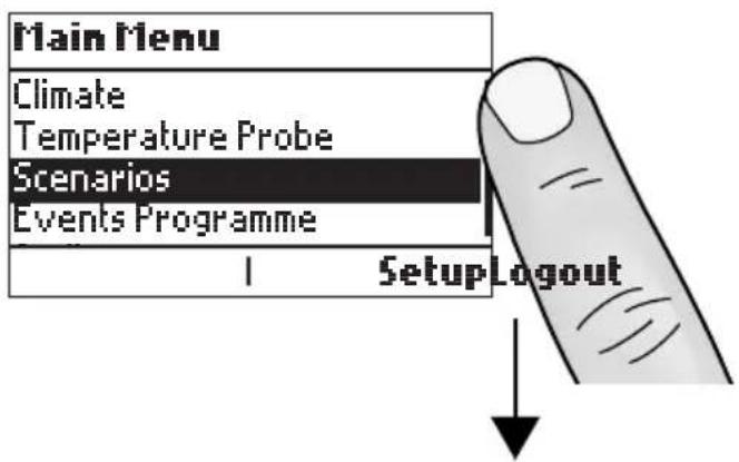
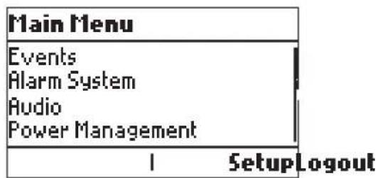
If, after a time-out of approximately 90 s, no operation is carried out, the control unit display switches off, activating a stand-by screen that displays the time, day and date.
If personal security codes have been set (installer PIN, different users, etc.), access to the menus is only possible after entering the code permitting use, by the user, only of the menus for which the user has been enabled (see paragraph 4.5.4).
Main configurations
4.4 Settings menu.
Used to adjust the control unit clock, language used, settings for the display and keypad tones, different profiles for accessing the control unit menus, the favourite applications to display on the start screen, to set the time-out to activate the screen saver and to manage the temperature probe.
4.4.1 Setting the clock.
Used to set the date and time.
Main Menu → Setup → Settings → Date and Time → Select Master or Slave
- Select Master → Solar or Daylight Saving or Automatic EU to manually set the date and time by to display and select the values; then confirm with Save.

- If you select Slave the date and time cannot be entered with the control panel (the display will show the popup) but will be set automatically by the web server (where applicable).
In both cases, the control panel will confirm the operation has been completed.
4.4.2 Language settings.
Used to set the national language in which the menus are displayed. The available languages are Italian, English, German, Spanish, French and Greek.
Note: If the user does not have the necessary privileges you will be asked to change user.
Main Menu → Setup → Settings → Language
The active language is signalled by the symbol ■; perform 📋 to scroll through the list of available languages and touch 🤒 the one you want. Confirm with Save; the control unit will display the confirmation of the operation.
4.4.3 Display and Tones.
Used to set the parameters of contrast and backlighting of the display, the tones of the icons for using and programming the control unit and performing the touch screen calibration function.
Main Menu → Setup → Settings → Display and Tones
It is then possible, by touching the desired one, to set the following parameters:
- Contrast of the Display → Use to select the desired value → Save
- Backlighting → Use to select the desired value → Save
- Keyboard tones → Use to select the desired value → Save
- Touch calibration (a pop-up will be displayed to illustrate the procedure to follow) → Next WARNING: It is not possible to stop the touch calibration function. Once started it must be completed.
To exit the menu touch Exit.
Main configurations
4.4.4 User Management.
The control unit enables setting different profiles to access the menus and in this way to configure the privileges (that is to say the methods of use according to the user); a total of 17 users can be set (one of which is the administrator).
At the time of first switching on, there are three types of user available on the control unit:
- Administrator, who has the right to perform every kind of operation and must always enter his or her password;
- Events Prog. User, whose partitions are called up when the intrusion detection alarm system is turned on/off using an automated program created with the Events menu.
- Guest, who has limited privileges that can however be changed at any time (guests do not enter passwords); It is therefore possible to customize access to system functions by creating different user profiles.
Warning: If there is also the intrusion detection alarm system and more than one user has been set, each one with a different partition for turning on the system, the Guest management privileges over the intrusion detection alarm system must be disabled.
Main Menu → Setup → Settings → User Management
N.B. Only the Administrator user can intervene on all the user settings, including the Guest user and the Events Prog. user, or add a new user.
4.4.4.1 Creating a new User
This menu enables creating new users assigning each one with the profile to access the control unit menus. The operation of creation can be carried out only by the Administrator user.
Main Menu → Setup → Settings → User Management → Select the Administrator user → Add
- Scroll with the 'through the list of characters left form the name of the new_user.
displayed and again with the 'to the right and
- Lastly confirm by touching Save.
The control unit will now ask for the user PIN.
- Enter the new PIN → OK.
- Confirm the entered PIN by touching OK. The control unit confirms the operation has been completed.
4.4.4.2 Administrator
The only activity that the Administrator user can perform is to change the PIN. This operation can be carried out only by the Administrator user.
Main Menu → Setup → Settings → User Management → Select the Administrator user → Administrator
The only activity that the Administrator user can perform is to change the PIN.
Touch Change PIN
- Enter the new PIN → OK.
- Confirm the entered PIN by touching OK. The control unit confirms the operation has been completed.
Main configurations
4.4.4.3 Events Prog. User
The only activity that the Events Prog. User can perform is to change the PIN. This operation can be carried out only by the Administrator user.
Main Menu → Setup → Settings → User Management → Select the Administrator user → Events Prog. User
The only activity that the Events Prog. User user can perform is to change the PIN.
Touch Change PIN
- Enter the new PIN → OK.
- Confirm the entered PIN by touching OK. The control unit confirms the operation has been completed.
4.4.4.4 Guest
The only activity that can be performed on the Guest user is to change the user privileges. This operation can be carried out only by the Administrator user.
Main Menu → Setup → Settings → User Management → Select the Administrator user → Guest
The only activity that the Administrator can perform on the Guest user is to change the User privileges.
Touch User privileges
- Scroll with 🤨 upwards or downwards through the list of values and touch 👍 the one you want.
4.4.4.5 Generic user
The activities that can be performed on a generic user are:
- Change user name: this operation can be carried out only by the Administrator user.
- Change PIN: this operation can be carried out by the Administrator' user and by the selfsame user.
- Change user privileges: this operation can be carried out only by the Administrator user.
- Remove user: this operation can be carried out only by the Administrator user.
Main Menu → Setup → Settings → User Management → Select the type of user (Administrator or user) → Guest
- Selecting User Name assigns a name to the user.
- Scroll, with through the list of characters and form the name by touching one by one, the desired letters; with a to the right you pass on to the next one while with a to the left you delete the selected one. - Lastly confirm by touching Save.
- Selecting Change PIN assigns or can change the password of the generic user.
- Selecting User Privileges assigns the profile for accessing the control unit menus such as Central Administration, Scenario Configuration, Thermostat Configuration, etc.
Main configurations
- Touch all the options that you want to assign to the user; the selected ones will be marked by the symbol ■.
- Lastly, touch Options → Save
The control unit will display the confirmation of the operation.
- Selecting User Name Remove User the current user will be deleted and the display will show the deletion has been made.
4.4.5 Favourite Application.
Used to set the start-up screen you want to be displayed.
Main Menu → Setup → Settings → Favourite Application
Scroll with upwards or downwards through the menu items and select the desired application; confirm lastly by touching Save.
The control unit confirms the operation has been completed.
4.4.6 Screen saver.
Used to set the time of inactivity at the end of which the control unit activates the screen saver and cuts off the display backlighting.
Main Menu → Setup → Settings → Screensaver
-Touching Off disables the screen saver.
-Touching 📋 Delay enables setting the inactivity time at the end of which the control unit activates the screen saver.
With 🎨 upwards or downwards select the desired value then touch 🎨 Set; the control unit confirms the operation carried out.
The activation time of the screen saver set by default is equal to 1 and a half minutes.
NB: If the screen saver is disabled, after 1 and a half minutes only the display backlighting is cut off.
4.4.7 Temperature Probe
Used to enable operation of the external probe that may be connected to the control unit to view the temperature measurement.
Main Menu → Setup → Settings → Temperature Probe
The available options are Status and Calibration.
- Status.
Select Enable to enable using the temperature probe or Disable to disable it.
Confirm by touching Save.
Main configurations
- Calibration.
Selecting this option starts the measuring system calibration procedure; this procedure can be carried out only with the sensor not connected.
As prescribed in the information pop-up shown on the display, make sure the probe is not connected and touch Next to start the auto-calibration mechanism.
The result of the calibration process is shown on the display with one of the following messages:
- Calibration performed successfully.
- Calibration failed. Repeat the operation.
Calibration completed successfully, it is possible to reconnect the probe to be able to view the value of the temperature measurement.
4.4.7.1 Use
Once the probe has been correctly configured and connected, it is possible to view the measured temperature.
Main Menu → Temperature Probe
If the external sensor is enabled, the display will show a screen that shows and periodically updates the current temperature measured by the sensor. The temperature value is given in the unit of measurement configured on the device (see the following paragraph 4.4.8).

Failure to enable the sensor is signalled by the message No temperature probe enabled.
Touching Menu takes you back to view the main menu of the control unit.
N.B.: If unexpected values are shown, it is necessary to check the connection of the probe to the control unit and if necessary carry out the calibration process again.
4.4.8 Temperature Unit
Used to select the temperature unit from degrees Celsius or degrees Fahrenheit.
Main Menu → Setup → Settings → Temperature Unit
Scroll upwards or downwards with 53 and select the desired unit of measurement; lastly touch Save.

The control unit confirms the operation has been completed.
Main configurations
4.5 Configuration menu.
CAUTION: For all the operations relative to the configuration of new devices 01480, 01481, 01482, 01485, 01486 and 01487, please refer to the sections "Home automation control equipment" on page 77.
Paragraph 4.5.1 and sub-paragraphs describe the procedures for configuration of pre-existing control equipment with codes matching the respective residential series.
4.5.1 Creating a new functional group.
As already described in chapter 2, the functional groups (set of functional units that operate together) are basic elements of the system, so the first operation is to create them.
The procedure to be carried out for each new group is as follows:
- Enter the Configuration menu and set the type of group (Automations, Load Control, etc.), the index and the name;
- Again from the Configuration menu, configure the desired functional unit;
- At the end of point 2. exit the Configuration menu of the created group.
4.5.1.1 Creating a new group.
Setup → Configuration → Groups
- Automation groups: generic group of the comfort system; this is the item to select in almost every case (lights, roller shutters....)
- Load control groups: group dedicated to load control
• HVAC group: group dedicated to HVAC management
• Audio groups: group dedicated to speaker system management - Intrusion detection alarm system groups: group dedicated to the configuration of discontinued Vimar intrusion detection alarm systems
Automations group → Add
Create the selected group:
- Index of new group (00-480) that identifies the number of the group in the list of all the configured ones; touch Next to confirm.
- New group name selecting, from among the names offered by a pre-set list, both the name of the group and the zone of application (necessary to distinguish between rooms and functions with the same name).
Lastly, proceed to save the name of the group by touching Save.
If the operation has been carried out correctly the control unit will show Operation completed successfully
By selecting the desired group it is possible to view the information related to the group such as the address and number of devices, the devices that may already be linked and to delete the group (Remove Group menu).
Main configurations
4.5.1.2 Functional unit selection and configuration.
WARNING:
For each device, how to select a functional unit is explained in the special instructions sheets that accompany the product.
To configure the various functional units within a group, carry out the following:
- Touch Setup → Configuration → Groups → Automation Groups (or Load Control, etc.).
- Select the name of the group to which you want to add the functional unit to configure.
- Select the group by scrolling through the list and Touch Add; the procedure is started on the control unit;
- Press the configuration button and, where necessary, the control button of the device to be included in the group;
- The device indicates that configuration is in progress by means of a red LED, which goes off when configuration is complete;
- The control unit indicates the functional unit that has just been configured;
- Proceed with the configuration of other functional units by repeating points 3, 4, 5 and 6 or press Back to exit.
Example 1.
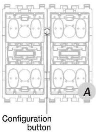
Functional units that can be selected by the control with 2 rocker switches with relay (Eikon 20526, Arké 19526, Idea 16966, Plana 14526).
Functional unit selection.
- To select the relay functional unit, press the configuration button (figure A);
- To select the left button functional unit, press the configuration button then the left button (figure B);
- To select the right button functional unit, press the configuration button then the right button (figure C).


Main configurations
Example 2.
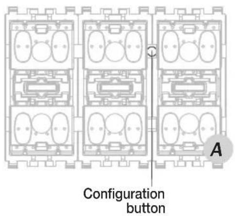
Functional units that can be selected by the control with 3 rocker switches with relay (Eikon 20546, Arké 19546, Idea 16986, Plana 14546).
Functional unit selection.
- To select the relay functional unit, press the configuration button (figure A);
- To select the left button functional unit, press the configuration button then the left button (figure B);
- To select the middle button functional unit, press the configuration button then the middle button (figure C).
- To select the right button functional unit, press the configuration button then the right button (figure D).
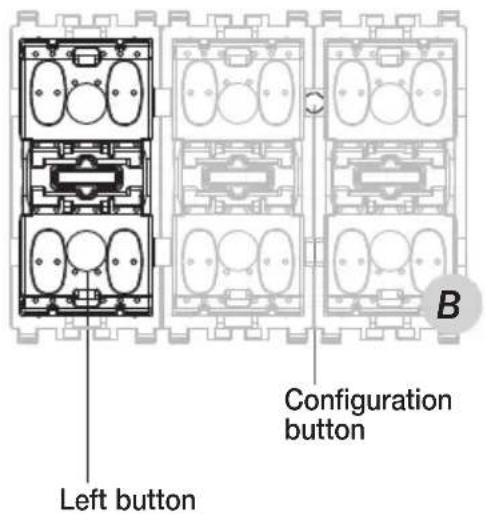

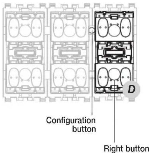
Main configurations
4.5.1.3 Rules for creating groups.
- Groups must comprise only functional units that are harmonious with each other: any one group cannot contain an actuator for roller shutters and an actuator to control the lighting of a lamp.
- In the phase of creating a group, first enlist the actuators and then the control devices (push buttons); in this way the control unit is able to recognize the type of group being created and to set the correct parameters on the buttons.
4.5.1.4 Note on built-in controls.
- The built-in controls must be installed with the bus terminal turned upwards (general rule for all built-in devices - figure 4.4.1.4.1).
- For the Idea and Plana series the "simple button" type of controls are distinguished by the grey of the button contact surface (figure 4.4.1.4.2); the "rocker switch" controls by green (figure 4.4.1.4.3).
- The buttons for devices such as "rocker switches" are distinguished by there being symbols or a plate both at the top and at the bottom (figure 4.4.1.4.4); apart from the blank button, the buttons for simple switches have symbols or a plate only at the bottom (figure 4.4.1.4.5).
- The buttons for simple switches have a direction of installation; when mounting the button, align the two slots inside the button with the slots on the lower side of the contact surface of the control (figure 4.4.1.4.2).
- The built-in control devices must be installed without buttons (these have to be attached only when the configuration of the system is complete). This is necessary in order to allow access to the configuration button (for the position of the configuration button, please refer to the instruction sheet for the device).
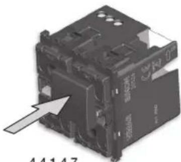
- Removing the button: using a small screwdriver, apply slight pressure and lever up the top part of the button (this has a small tab) from the body of the device (figure 4.4.1.4.6), then take out the button.
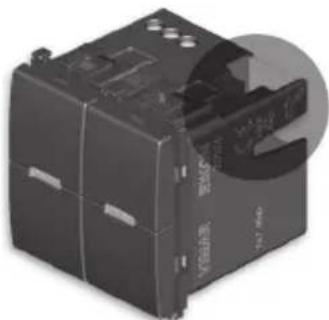
natural_image
Close-up of a black electronic component with visible ports and mounting holes (no readable text or symbols)4.4.1.4.1

natural_image
Pure electrical circuit lines without any symbols4.4.1.4.2 4.4.1.4.3
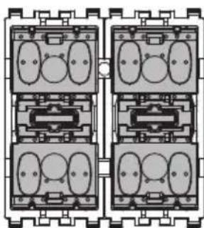
natural_image
Pure electrical circuit lines without any symbols
natural_image
Two identical rectangular panels with internal resistors and a separate gray rectangle, no text or symbols present.
natural_image
Pure electrical circuit lines without any symbols4.4.1.4.4 4.4.1.4.5
Main configurations
- Mounting the button: position the button in the button-holder and press lightly (figure 4.4.1.4.7).

natural_image
Close-up of a black industrial electrical contactor component with a white arrow pointing to its top section (no visible text or symbols)4.4.1.4.6
natural_image
3D rendering of an electronic component with a white arrow pointing to it, no visible text or symbols on the main body.4.4.1.4.7
IMPORTANT: Obviously, all the considerations made in par. 4.4.1.4 apply both for the appliances with 2 buttons and for the 3-button devices.
4.5.2 Add devices to a functional group.
Used to add additional devices to an existing functional group.
Setup → Configuration → Groups → Automation groups → Select the group scrolling through the list → Add
Configure the functional units as described in paragraph 4.4.
N.B.
If a user is to be controlled using infrared remote control 01849, it is necessary to configure the infrared receiver (Eikon 20516, Arké 19516, Idea 16956, Plana 14516) inside the group that contains the relay actuator (or regulator) connected to the load to be controlled (or regulated).
For example, by creating a group made up of a relay actuator (Eikon 20535, Arké 19535, Idea 16795, Plana 14535, for DIN (60715 TH35) rail 01850.2) and infrared receiver (Eikon 20516, Arké 19516, Idea 16956, Plana 14516) connected to a lamp, the lamp can be controlled using infrared remote control 01849.
The procedure for configuring the infrared receiver is described in the instruction sheet that accompanies the product.
Main configurations
4.5.3 Remove a functional unit from a functional group.
Used to remove functional units from a functional group.
Setup → Configuration → Groups → Automation groups → Select the group scrolling through the list → Associated devices → Select the functional unit to remove → Remove device
Proceed to remove the device Yes
If the operation has been carried out correctly the control unit will show Operation completed successfully
4.5.4 Modifying device parameters.
Device parameters can be modified in order to personalize operation to adapt the system to the various installation requirements.
Setup → Configuration → Groups → Automation groups → Select the group scrolling through the list → Associated devices → Select the functional unit scrolling through the list → Device parameters
The modifiable parameters for each functional unit depend on the characteristics of the unit and vary by type depending on the device considered (see the instructions sheets provided with each article).
4.5.5 Changing the name of a group.
Used to rename an existing group.
Setup → Configuration → Groups → Automation groups → Select the group scrolling through the list → Edit group name
Choose the name of the group and the location from the names given in a pre-set list; lastly, save the name by touching Save.
It is now possible with the same procedure to rename another group.
4.5.6 Removing a group.
Used to remove an existing functional group.
Setup → Configuration → Groups → Automation groups → Select the group scrolling through the list → Remove group
Delete all information associated with the selected Group → Yes
The control unit confirms removal and goes back to displaying the list of groups.
Main configurations
4.5.7 Device identification.
It is possible to display information on a device that has already been configured such as its physical address and the group to which it belongs.
Setup → Configuration → Device identification
On pressing the configuration button of a device, the control unit displays the physical address and the type of device (Dimmer, RF interface, etc.).
Then press the configuration button for the device you want to identify; at the end of this process, touch End and the control unit will show the list of all the device's functional units.
On selecting the functional unit from the list and touching it, the following will be displayed:
- Information: to view the information on the device itself;
- Own Scenarios: to view its own scenarios (number and name);
- Own Groups: 📋 to view its own groups (number and name).
4.5.8 Device reset.
Used to delete the configuration and settings saved by one or more devices.
Setup → Configuration → Reset management → Device reset
Press and hold down the configuration button for the device you want to reset; the red LED will come on (in some cases after a few seconds).
When the LED goes out, release the device button, then touch End on the control unit.
As regards the thermostats (Eikon 20513-20514, Arké 19513-19514, Idea 16953-16954, Plana 14513-14514) the procedure is similar; the button to press is the first one on the left (on the device instructions sheet it is called A) and you need to wait for the display to stop showing the CNF icon.
N.B.
When resetting control devices with two simple push-buttons and actuator (Eikon 20525, Arké 19525, Idea 16965, Plana 14525) and control devices with two toggle switches and actuator (Eikon 20526, Arké 19526, Idea 16966, Plana 14526), the relay actuator in the device is always associated with the left button on the device concerned.
4.5.9 Control unit reset.
Used to restore the factory conditions on the control unit; all the saved data are therefore deleted.
Setup → Configuration → Reset management → Control unit reset
The control unit requests confirmation of the operation, go ahead with Yes.
Main configurations
4.5.10 Device parameters.
- Functional unit – Left push button
Operation: toggle, only ON, only OFF, push-button (it sends ON on pressing the button and OFF on releasing it). LED management: off, normal, reverse, always on, normal central LED, reverse central LED, central LED always on. Default parameters: Op. - Toggle, LED control - normal
- Functional unit - Middle button (only for single buttons with 3 modules)
Operation: toggle, only ON, only OFF, push-button (it sends ON on pressing the button and OFF on releasing it). LED management: off, normal, reverse, always on, normal central LED, reverse central LED, central LED always on. Default parameters: Op. - Toggle, LED control - normal
- Functional unit – Right push button
Operation: toggle, only ON, only OFF, push-button (it sends ON on pressing the button and OFF on releasing it). LED management: off, normal, reverse, always on, normal central LED, reverse central LED, central LED always on. Default parameters: Op. - Toggle, LED control - normal
- Functional unit – Left rocker switch
Operation ON/OFF, dimmer switch, roll-up blind switch LED management: off, normal, reverse, always on, normal central LED, reverse central LED, central LED always on. Default parameters: Op. - on/off, LED control - normal
- Functional unit - Middle rocker switch (only for rocker switches with 3 modules)
Operation ON/OFF, dimmer switch, roll-up blind switch LED management: off, normal, reverse, always on, normal central LED, reverse central LED, central LED always on. Default parameters: Op. - on/off, LED control - normal
- Functional unit – Right rocker switch
Operation ON/OFF, dimmer switch, roll-up blind switch LED management: off, normal, reverse, always on. Default parameters: Op. - Toggle, LED control - normal
• Functional unit - Relay
Operation: one- or two-position stable On time-delay: from 0 to 200 s; then at intervals of one minute from 1 to 50 min. Off time-delay: from 0 to 200 s; then at intervals of one minute from 1 to 50 min. Default parameters: Op. - Two-Position Stable, On Delay - 0, Off Delay - 0.
• Functional unit - dimmer
Adjustment speed: low, medium or high. Default parameters: Speed setting - medium
- Command 10 V -
Adjustment speed: low, medium or high. Default parameters: Speed setting - medium
- Contact interface with 2 inputs
Input operation: normal, reverse, toggle (on opening or on closing), only ON, only OFF, scenario Default parameters: Normal op
Main configurations
• Interface for traditional controls
Rocker operation: normal, reverse
Button operation: toggle on up, toggle on down
LED management: off, on (it is enough for one of the two inputs to be active for the LED to come on)
Default parameters: Op. - Normal, Mgt. LED - On
N.B.: For art. 20518, 16958 and 14518 there are also the parameters Only ON and Only OFF.
- Roller shutter actuator
Deactivation delay: adjustable from 0 to 250 s.
Scenario activation delay: adjustable from 0 to 250 s.
Control activation delay: adjustable from 0 to 250 s.
Default parameters: Op. - Toggle, LED control - normal
- Actuator for roller shutters and blinds (01852.2):
Operation: set the actuator operating mode, namely 0 -> "Normal" and 1 -> "Blinds".
- With the 0 (Normal) setting the device controls only the roller shutters and the typical parameter of blinds operation will not be displayed (Step duration).
- With the 1 (Blinds) setting the device controls not only the roller shutters but also the Venetian blinds and it will be necessary to set the "Step Duration" parameter that identifies the length of the pulse with which the actuator will drive the motor to rotate the laths (that is it is used to determine how far you want to turn the blinds around their axis on briefly pressing the rocker switch).
Step duration: adjustable from 70 ms to 3 s in steps of 10 ms.
The movement of the blinds is affected by briefly pressing or holding down the control button that governs them according to the following modes:
a. Briefly pressing the control button: the laths move by one click.
b. Pressing and holding down the control button: the laths turn completely and raise or lower, depending on the button being pressed.
c. Briefly pressing the control button while the laths are moving: the laths stop without completing the closing or opening movement.
Deactivation delay: adjustable from 0 to 250 s.
Scenario activation delay: adjustable from 0 to 250 s.
Control activation delay: adjustable from 0 to 250 s.
Default parameters: Operation - 0, Op. - Toggle, LED control - normal.
• Infrared remote control receiver
Button operation: toggle, push-button (it sends ON on pressing the button and OFF on releasing it).
Rocker operation: on/off, dimmer switch, roller shutter switch
LED management: off, on in reception, always on
Default parameters: Op. for Push-button - Toggle, Op. for Push-button - on/off, LED control - normal
- IR detector, with dual technology and wall-mounting, mini)
Brightness threshold: settable from 0 to 100 (when the setting is equal to 100, the detector operates in a situation of total darkness).
Default parameters: Brightness threshold - 250
Main configurations
• Control device with three rocker switches and regulator actuator MASTER 20548, 16988, 14548
- The regulators also control inductive response electronic transformers 40-200 VA 230 V\~50 Hz (200 VA maxfor 2 transformers); do not connect any more than 2 transformers.
- Not suitable for controlling motors (e.g. fans, ventilators).
- If installing 2 regulators in a single box, the loads that can be controlled by each regulator must be reduced so that their total does not exceed the values indicated in the following table:
| Controllable loads | Characteristics of controllable transformer | 205481698814548MASTER |
 | - | 40 - 300 W |
 | - | 40 - 300 VA |
 |  | 40 - 200 VA |
- The rated power level should never be exceeded.
- Overloading, power surges and short-circuits may permanently damage dimmers. Before installation check the circuit carefully and eliminate any of the above causes.
- Do not connect several dimmers in series between each other.
- The dimmer does not have a mechanical circuit breaker in the main circuit and so is not galvanically separated.
The circuit load should be considered always powered.
4.5.11 Configuration of Actuator with 4 relay outputs 01471
The functional blocks that the device makes available comprise: 4 relays or 2 relays + 1 roller shutter or 2 roller shutters or 1 fan coil.
The Fancoil functional block has a group depth of 1 (that is, it can belong to one group only).
Description of the functional blocks
ACTUATOR
- Actuator: to manage a lights actuator.
This functional block receives the following command requests: load on/off, timed load switch on, saving and recalling scenes.
- Timer controlled actuator: for control and also timer control of a lighting actuator.
Receives the following command requests: timer controlled load on/off, load on/off, scenario save and recall.
ROLLER SHUTTER ACTUATOR
- Roller shutter actuator: to manage the roller shutter.
- Blinds: to manage the roller shutter + slat
These functional blocks receive the following command requests: opening/closing roller shutters, rotating slats, setting the roller shutter height and slat rotation values, saving and recalling scenes, forcing via logic module.
Main configurations
FANCOIL
- 2 or 4 pipe fancoils or integrations with third parties (controlled by devices that send a proportional value (for example art.02951).
Functional blocks
- For each single relay, you can select the functional block:
- actuator
- timer controlled actuator
- For the pairs of relays (relay 1+ relay 2 or relay 3 + relay 4) you can select one of the following functional blocks:
- roller shutter actuator
- blinds actuator
Caution: After installation you need to open and close each roller shutter completely to carry out the calibration process.
- For the 4 relays used in a single block, you can select one of the following functional blocks:
- 2/4-pipe fancoil: the control unit automatically selects the functional block according to the configuration of the thermostat already present in the group.
- integrating third-party fancoil
Selecting the functional block to be configured:
Press the configuration button to select the first functional block; keeping it pressed cycles through the list of functional blocks.
The LEDs on the OUT 1, 2, 3 and 4 buttons indicate the selected functional block:
• OUT1 on for functional block relay 1
• OUT2 on for functional block relay 2
• OUT3 on for functional block relay 3
• OUT4 on for functional block relay 4
• OUT1 and OUT2 on for functional block roller shutter 1
• OUT3 and OUT4 on for functional block roller shutter 2
• OUT1, OUT2, OUT3, OUT4 on for functional block fancoil
After a pause of 3 s the device enters configuration mode for the selected functional block and the start of configuration is signalled by the red LED. At the end of this operation the red LED will go out.
Scenes.
The actuator can belong to multiple scenes and, for each one of them, save the status (ON or OFF) to retrieve when activating the scene itself.
The roller shutter actuator can save and recall the height of the roller shutter.
The blinds actuator can save and recall the height of the roller shutter and the angle of the slats.
Description of the parameters
ACTUATOR AND TIMER CONTROLLED ACTUATOR
- On and off delay (they are delay times that can be set for actuating the On and Off request): from 0 s to 12 h with default value 0 s.
- ON time duration for one-position stable operation (this is the activation time for one-position stable operation): from 1 s to 12 h with default value 30 s.
Main configurations
- Warning time (this is a time that is added to the activation time of the one-position stable actuator. At the end of the activation time the relay switches off for 0.5 s and then switches back on for the warning time): from 0 s to 12 h with default value 0 s.
- Output status at power on and output status at power down (this enables setting the actuator when switching off and upon restoring power respectively): ON/OFF/Unchanged with default value "Unchanged".
- Operation (this enables setting the operation of the actuator): one-position stable/two-position stable with default value "two-position stable" (this parameter is not present for the timer controlled actuator functional block).
- Feedback group (this enables setting the group on which to send the actuator status to align the LEDs of the commands): for details see par. 3.4 of the Plug&Play Home Automation System section.
ROLLER SHUTTER AND BLINDS ACTUATOR
- Up and down time (these are the roller shutter up and down times): 10 s to 1 h with default value 180 s.
- Full slat rotation time: from 500 ms to 5 s with default value 2 s.
- Behaviour at power on (this enables setting whether when power is restored the roller shutter opens, closes, remains in the current position or you can choose the height of the roller shutter and the tilt of the slats): all down, all up, no action, default position. Default value no "action".
- Position of the roller shutter at power on (enables setting the position of the roller shutter when power is restored): from 0 to 100% with default value 50% .
- Scene recall execution delay (this enables delaying execution of the command so as not to actuate all the roller shutters at once): from 0 s to 250 s with default value 0 s.
- Command execution delay: from 0 s to 250 s with default value 0 s.
- Tilt of the slats at power on (enables setting the position of the slat when power is restored): from 0 to 100% with default value 50% .
- Position on forcing (this enables setting the behaviour of the roller shutter upon the forcing request): all down, all up, fixed, preset position with default value "fixed." It is necessary to observe the value set by the "roller shutter position on forcing" and "slat tilt on forcing" parameters.
- Position on end of forcing (this enables setting the behaviour of the roller shutter at the end of forcing): all down, all up, fixed, preset position with default value "fixed." It is necessary to observe the value set by the "roller shutter position on forcing" and "slat tilt on forcing" parameters; it returns to the previous value with the request for forcing.
- Roller shutter position on forcing (can be used in the "position on forcing" and "position on end of forcing" parameters): from 0 to 100% with default value 50% .
- Slat tilt on forcing (can be used in the "position on forcing" and "position on end of forcing" parameters): from 0 to 100% with default value 50% .
FANCOIL
- Valve control (enables selecting whether to control the hot or cold valve). Default value "heating valve".
Chap. 4 of the Plug&Play Home Automation System section contains some time charts describing the operation of the roller shutter and relay actuators depending on the settings made during configuration and on the parameters.
Main configurations
4.5.12 Installing and configuring the touch screens
The colour touch screens (art. 21553.2, 21554, 21511.1, 21512.1) enable controlling lights, roller shutters, HVAC, scenarios, etc., by touching the icons associated with them.
The configuration of the touchscreen is done with the EasyTool Professional software connecting the interface 01998 to the special connector on the device..
On concluding this operation, it is necessary to configure the touch screen in the By-me system so that it is recognized by the control unit and can interact with the system.
The device can be connected to any of the lines of the automation system (take care not to connect it to the line reserved for the intrusion detection alarm system).
Having done this, the touch screen must be configured in a group of the automation system via the menu:
Setup → Configuration → Groups → Automation groups → Select the group scrolling through the list → Associated devices → Add
To configure the touch screen, starting from the main screen, touch these icons in the following order:
switch off on concluding the configuration.
WARNING: Once you have downloaded the touch screen screen shots with EasyTool Professional and have configured it on the By-me control unit, you will then need to synchronise the touch screen router by touching the icon in the icon. On touching the icon it will light up and it will
switch off on concluding the configuration.
- Resetting the touchscreen
To reset the touchscreen, carry out the following operations:
- on the control unit select the menu called Setup → Configuration → Reset management → Device reset;
-touch and keep the 'toon pressed' until the touchscreen switches off.
The touchscreen is now reset and it is necessary to once more download the screens set with EasyTool Professional.
Main configurations
4.5.13 Installation and configuration of the By-me module 01965.
The By-me module 01965 is a device which must be integrated into the video door entry unit 19558 and allows managing not only the video door entry system, but also all the functions of the By-me automation system such as the lights control, roller shutters, HVAC, sound system, scenarios, events, and load control. The configuration of the module 01965 is done with the EasyTool Professional software connecting the interface 01998 to the special connector on the device.
On concluding this operation, it is necessary to configure the module in the By-me system so that it is recognized by the control unit and can interact with the system.
The device can be connected to any of the lines of the automation system (take care not to connect it to the line reserved for the intrusion detection alarm system).
Having done this, the module must be configured in a group of the automation system via the control panel menu:
Setup → Configuration → Groups → Automation groups → Select the group scrolling through the list → Associated devices → Add
To configure the module 01965, starting from the main menu, tap the softkeys in sequence corresponding to the following icons:


The display of the video door entry unit will show the following screen:

Main configurations
Tap the softkey corresponding to the icon ④ bottom right to start the configuration.
Once the operation has concluded, it is necessary to synchronize the router; using and se

and tap the softkey corresponding to the icon

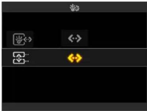
Once the operation has concluded, the display will show whether synchronization has taken place correctly.
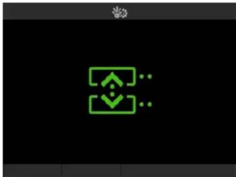
Synchronization good

Error
Main configurations
4.5.14 Router Control
The Router Control menu enables configuring the Line Coupler art. 01845.1, called "Router" in the control unit, creating a new line, as per bus system architecture.
NOTE: the configured router identifies a new line/area that will lead to the terminals indicated with BUS 2, while the backbone will lead to the BUS 1 terminals. The devices connected on the BUS 2 side will be addressed with the Area and Line number of the Router.
- Configuration of the router.
Setup → Configuration → Router → Router management → Add
Set the Area and Line number to assign to the Router and touch (My) Next.
Press the configuration button on Line Coupler 01845.1 until the red Led lights up on the device. Completion of this operation is confirmed by a message on the control unit display and by the red LED going out on the device.
- Router synchronization.
Setup → Configuration → Router → Router synchronization
Confirm the operation by touching

After configuring the devices, this operation enables the Routers controlled by the control unit, allowing the group messages to get past the line coupler.
In the phase of group management it is allowed to configure devices belonging to different lines in the same group.
At the end, the synchronization of the Routers prevents filtering the group messages.
NOTE: It is permissible to create actuator control groups on different lines.
- Manual enabling of the messages filtered by the router.
This procedure enables manually passing or blocking the messages from one or more groups in the system (automation groups, temperature zones) via a Router selected from the ones installed in the system.
Setup → Configuration → Router → Router management
Select the Router on which you want to manually enable/disable the flow of messages from a group; the router will be identified with the wording Area no./Line no.
The control unit will display the following four options:
- Add group that enables adding a single group of the By-me system; select the desired group scrolling through the list and, after making the selection, confirm by touching Save.
- Remove group that enables removing a single group of the By-me system; select the desired group scrolling through the list and, after making the selection, confirm by touching Save.
Finally a pop-up is displayed; touch

Main configurations
- Add the address that enables adding a single group address for KNX networks; form the hexadecimal number with the right to enter and on the left to delete the numbers forming the hexadecimal address and, after making the selection, confirm the choice by touching Next.
- Remove the address that enables removing a single group address for KNX networks; form the hexadecimal number with the right to enter and on the left to delete the numbers forming the hexadecimal address and, after making the selection, confirm the choice by touching Yes.
At the end of each operation, exit the menus and the new groups selected will be filtered by the Router according to the set choices.
- Removing a router
Setup → Configuration → Router → Router management → Select the router to remove by scrolling through the list → Remove router
Proceed to remove → Yes
The control unit confirms removal and goes back to displaying the list of routers.
Main configurations
4.5.15 Communicator interface management.
The following menus are used to configure the Internal communication interface between the BUS system and the phone communicators 01941 and 01942.
Setup → Configuration → Communicator interface → Configuration
Select the interface to configure (identified with Area no./Line no.) and touch Next.
Press the configuration button of the internal communications interface between the BUS system and the telephone communicators. The red LED lights up on the device.
The end of the operation is confirmed by a message on the control unit and the device's red LED going out; now switch the communicator off and back on again.
• Phone Communicator Configuration.
This menu is used to activate the configuration procedure:
Setup → Configuration → Communicator interface → Authentication
The communicator is thus automatically configured and the control unit confirms completion of the operation.
- Add group to interface.
When a group is added, the messages sent to that group are no longer blocked by the internal communication interface between the bus system and the phone communicator so as to be able to thus be managed by the communicator.
Setup → Configuration → Communicator interface → Add group
Select the desired group by scrolling through the list of groups and confirm by touching ( ^1 ) Save.
The control unit confirms the operation and returns to the list of menus for the Communicator interface.
An example of the usefulness of this menu is the management of the technical alarms of a By-me system via the phone communicator: if, following a technical alarm detected in the control unit, you want the communicator to send an alarm message (SMS or voice message), it is necessary to add the group for the contacts interface generating the technical alarm to the communicator interface.
- Remove group from interface.
Setup → Configuration → Communicator interface → Remove group
Select the group to remove by scrolling through the list of displayed groups.
Proceed to remove the Group? → Yes
- Groups Monitored from a remote location.
This menu is used to enable the selected groups (that contain at least one actuator device) for remote control via a communicator; it is then possible to turn reading the state of the groups on and off.
Up to 8 groups can be selected for monitoring.
Setup → Configuration → Communicator interface → Monitor groups
Main configurations
Select the desired groups by scrolling through the list of all the configured ones and confirm by touching Save.
Go on to configure the telephone communicator (01941 or 01942) by following the procedures described in the communicator instructions manual.
- Removing interface.
Setup → Configuration → Communicator interface → Remove interface
Proceed to remove the communicator interface? → Yes
The communicator interface will be removed from the system.
The GSM communicator moreover enables carrying out diagnostics operations from a remote location; for all the details please see chap. 8 "Diagnostics and maintenance" on page 74.
4.5.16 USB Interface Management 01847
The menus illustrated in this paragraph allow configuring the interface 01847 for connecting the bus of the By-me system with the PC on which the EasyTool Professional program is installed. The interface 01847 is supplied with art. 01994; see the relevant instructions sheet for the details about connecting the device.
- Configuring the USB interface.
Connect, via the dedicated RJ11 socket, the interface to the bus to which the By-me control panel is connected.
From the menu:
Setup → Configuration → USB interface → Configuration → Select the interface (Area/Line)
Press the USB 0 interface configuration button for approximately two seconds; the control unit display will, for approximately two seconds, show a message confirming the configuration.
At the end of this message the control unit will again display the USB Interface menu.
• Authentication of interface 01847.
For the USB interface to enable managing the By-me system via EasyTool Professional it is necessary not only to configure it but also authenticate it; the procedure is as follows:
Setup → Configuration → USB interface → Authentication
The control unit display will, for approximately two seconds, show a message confirming the configuration.
At the end of this message the control unit will again display the USB Interface menu.
Main configurations
- Removing interface 01847.
Setup → Configuration → USB interface → Remove USB interface
Proceed to remove the USB interface? → Yes
The USB interface will be removed from the system.
4.5.17 Configuration of logic unit 01468
The device must be configured in an automation group, Setup → Configuration → Groups → Automation Groups by pressing the CONF button; you are advised to configure a group dedicated exclusively to the logic unit.
More generally, when configuring a logic unit, keep in mind the following:
- the device is configured in an automation group and only on an automation line
- you can configure multiple "logic unit" automation groups per control unit
- more than one logic unit can be configured per automation group without any constraints, but it can only coexist with similar devices.
In particular, it may be useful to group the logic modules in different groups (if the installer considers it appropriate) to identify different group nomenclature.
The configuration of the device logics is done using the EasyTool Professional software.
Before transferring the programmes to the logic unit, you are advised to check them in the EasyTool Professional editor using the "SIMULATION" function; this is used to enter the possible values received from the bus manually and check the correct behaviour of the logic networks.
Updating the logic unit firmware.
To update the device firmware, proceed as follows:
- Switch off the connection to the By-me bus.
- Run the firmware update tool on EasyTool Professional, which will wait for the device.
- When requested by the software, press the device configuration button, then connect the logic unit to the computer via a cable and USB port, while holding down the configuration button; once the cable has been fitted in the USB port, wait one more second and then release the button.
Main configurations
4.5.18 Web Server management
The menus illustrated in this paragraph are used to configure the Web Server 01945-01946 so that the By-me system can be managed remotely via a PC or Apple mobile devices or locally by means of the multimedia video touch screen 21553.2.
For all the details on the connection of the Web Server please see the relevant instructions sheet.
- Configuration of the Web Server.
If the system includes an intrusion detection alarm system, connect the Web Server paying the utmost attention to check that the device is connected to the line reserved for the intrusion detection alarm system (Area 00, line 00).
If, on the contrary, the system has no intrusion detection alarm system it suffices to connect the Web Server to the line of the bus on which the control unit is connected.
From the menu:
Setup → Configuration → Web Server → Configuration
The control unit display will, for approximately two seconds, show a message confirming the configuration.
At the end of this message the control unit will again display the Web Server menu.
• Authentication of the Web Server.
For the Web Server to enable managing the By-me system it is necessary not only to configure it but also authenticate it; the procedure is as follows:
Setup → Configuration → Web Server → Authentication
The control unit display will, for approximately two seconds, show a message confirming the configuration.
At the end of this message the control unit will again display the Web Server menu.
- Removing the Web Server.
Setup → Configuration → Web Server → Remove Web Server
Proceed to remove the Web Server? → Yes
The Web Server will be removed from the system.
Main configurations
4.5.19 Managing BUS interface with EnOcean module
The BUS with EnOcean module radio interface allows using the devices of the radiofrequency system to extend coverage in places or accesses where it is not possible to add any cables and devices via BUS.
It is supplied in the following versions:
20508 : 2 Eikon modules
19508 : 2 Arké modules
14508 : 2 Plana modules
The radio interface is combined with the following radio-frequency devices with the EnOcean module:
20505-03955: control with 2 toggle buttons
01796.1: relay actuator with relay output
- Operation
The device communicates on the one hand via radio wave signals with the radio-frequency devices with the EnOcean module and, on the other hand, with the devices in the system communication bus.
The functions involve the automation operations such as controlling lights, roller shade control and scenario management.
Devices with the Enocean module integrate completely with the By-me devices: for example, it is possible in an Automation group to have a By-me button that commands an EnOcean actuator or an EnOcean button that commands a By-me actuator; devices with an EnOcean module moreover also take part in creating scenarios. In a system it is possible to add up to 15 BUS interfaces with the EnOcean module and each one of them can control at most 16 devices with the EnOcean module.
The maximum number of RF devices with the EnOcean module and SAI that can be saved in the database of the control unit is 350.
Important:
- an interface cannot be added to more than one Automation Group;
- an EnOcean button control device can be added to at most four Automation groups per interface;
- a relay actuator device with the EnOcean module can be added to at most 30 groups;
- actuators join scenarios when the group to which they belong is associated with a scenario.
The BUS interface with the EnOcean module features two main modes of operation:
- Normal operation: receives information from the radio-frequency devices and sends it through the communication bus, and vice versa.
- Configuration: in the phase of adding radio frequency devices it saves the characteristics of the component that has responded and communicates some information to the control unit.
Main configurations

flowchart
graph TD
    A["Controls"] --> B["Relay actuator"]
    B --> C["Controls with relay actuator"]
    C --> D["Controls with roller shade actuator"]
    D --> E["RF actuator 01796.1"]
    E --> F["RF command buttons"]
    G["Control unit 21509"] --> H["SETUP"]
    H --> I["INFORMATION"]
    I --> J["CONTROL"]
    J --> K["INFORMATION"]
    K --> L["INFORMATION"]
    L --> M["INFORMATION"]
    M --> N["INFORMATION"]
    N --> O["INFORMATION"]
    O --> P["RF BUS interface 20508-19508-14508"]
    P --> Q["RF command buttons"]
Example of connecting devices with EnOcean module integrated in the By-me automation system.
- Interface configuration.
An interface must always be associated with an automation group.
The first operation to be carried out therefore consists in creating the group:
Setup → Configuration → Groups → Automation groups → Add
The new group is saved in the database.
The second operation consists in associating the interface with the group:
Setup → Configuration → Groups → Automation groups → Select the name of the group just created → Add
Then press the configuration button in the interface to add it to the created group.
WARNING: The 20508-19508-14508 interface can be added to one group only.
Note: For practical purposes it is not important in which group the interface 20508-19508-14508 is configured; but it is advisable to include it in one of the first automation groups for faster access to the menus.
Main configurations
- Removing the interface.
Setup → Configuration → Groups → Automation groups → Select the name of the group to which the interface belongs → Associated devices
Select the functional unit related to the interface to remove by scrolling through the list of units and touch Remove Device; the control unit displays:
Proceed to remove the device? → Yes
The control unit signals deletion; together with the interface, all the devices with the EnOcean module associated with it are removed from the database, and that is the button controls in the Automation groups, the button controls associated with the scenarios and the relay actuators.
WARNING: To complete the procedure it is necessary to reset the radio relay actuators associated with the interface. If any of these actuators have been configured in other interfaces too, the relay will stop working; it is then necessary to remove them and reconfigure them in the relevant groups.
• Interface diagnostics.
This option permits checking the operation of the interfaces with the EnOcean module and managing their replacement.
Setup → Diagnostics → Device diagnostics
The control unit initiates a scan procedure to check that all the configured devices are functioning correctly. In case of error and subsequent replacement of the interface 20508-19508-14508, besides the configuration information, also the related devices with the EnOcean module previously associated with it are restored.
• Device configuration
This procedure allows associating the interface with the EnOcean module with the radio rocker switches (20505-03955 + 20506 or 20505-03955 +14506) and the radio relay actuator 01796.1.
Select the group where the BUS interface with the EnOcean module has been inserted.
Scroll through the list of devices to the desired interface, select it and enter Device parameters; scroll through the list of parameters to the item RF devices and select View.
Select the desired group from the existing ones; add the device selecting the desired type of control choosing between button control and relay control.
Setup → Configuration → Groups → Automation groups → Select the name of the group to which the interface belongs → Select the interface → Device parameters → RF devices → Add → Add Button/Relay → Select the name of the group
The configuration procedure now depends on the type of control selected.
Add Button: Press the desired button (left or right) of the device with the EnOcean module.
Add Relay: Press the LRN button of the relay actuator 01796.1; lastly press the configuration button on the interface to complete the procedure correctly.
The radio interface sends a message to the control unit that shows the information related to the device code and its description on the display.
Then repeat the operation for each device that you want to add.
Main configurations
Touching 🖱️ End takes you back to the previous menu that shows all the devices added on the interface, displaying the code, description and index of the associated automation group.
In addition, it is possible to add the same device with the EnOcean module on more than one interface, each one in a different group, in order to increase the system's radio coverage; likewise it is possible to add a device on a single interface associating it to more than one group. In both cases the group depth is equal to 4.
Note: If adding a button on different interfaces belonging to the same group, it must continue to have the same type in relation to the type of actuator (on/off, dimmer, roller shutters).
For further details, please refer to the manual of interface 20508-19508-14508.
- Removing devices
This option enables removing a single device with the EnOcean module from an interface; it can be removed in two ways:
Setup → Configuration → Groups → Automation groups → Select the name of the group to which the interface belongs → Select the interface → Device parameters → RF device → View
Scrolling through the list, select the device you want to remove and touch Remove Device.
Likewise, removal can be performed as follows:
Setup → Configuration → Groups → Automation groups
In the desired group, select the functional unit to be removed by scrolling through the list; the removal procedure depends on the type of device that has to be removed:
- RF button: Touch Remove device on the control unit menu.
- RF relay: Press the LRN button of the radio actuator to remove and subsequently touch Remove device on the control unit menu.
Warning: It is not possible to remove a group containing buttons and actuators with the EnOcean module without having first removed them from this group.
- Changing interface parameters
The interface with the EnOcean module features some operating parameters that can be set by the user.
Setup → Configuration → Groups → Automation groups → Select the name of the group to which the interface belongs → Select the interface → Device parameters
The available interface parameters are:
• Interface LED blink mode:
- Off = the green LED never lights up;
- Normal = the green LED is off whereas it blinks when it receives an RF message;
- Inverted = the green LED is on whereas it blinks when it receives an RF message;
- RF devices:
- View = access to the menu for displaying all the RF devices associated with the interface and for Add Device.
Main configurations
- Interface number:
- Progressive interface number, from 1 to 15, assigned automatically by the control unit and that cannot be modified.
- Changing the parameters of the device with the EnOcean module
This option allows changing the parameters related to the radio devices with the EnOcean module.
The device with the EnOcean module is displayed in the menu of the Automations group with which it is associated.
Setup → Configuration → Groups → Automation groups → Select the group
Scroll through the list of units, select the functional unit for which you want to change the parameters and finally touch Device parameters.
On the rocker switch device with the EnOcean module it is possible to change the type of associated command; the available types are the following:
- On/Off;
- Dimmer control;
- Roller shutter control.
Select the desired type of control and touch Set; lastly press Save.
The relay actuator with the EnOcean module has no parameters.
As regards the address taken by the devices with the EnOcean module, it will have Area equal to 0, Line equal to the number of the interface with which it is associated, and device number ranging from 1 to 50.
For example
- 0x0101 corresponds to device no. 1 of interface no. 1;
- 0x0F32 corresponds to device no. 50 of interface no. 15.
- Scenario management with rocker switch control with EnOcean module
In the range of devices with the EnOcean module, the button control (20505-03955 + 20506 or 20505-03955 + 14506) can be used in scenario management as an external button.
The procedure for associating the button with the desired scenario is as follows:
Scenarios → Setup → Select the scenario to associate → Associated buttons → Add
It is now necessary first of all to identify the interface that is located at a suitable distance for receiving the radio signal; having done this, press its configuration button.
Again on the control unit menu select the top or bottom side of the button on which to activate the command, touch Next finally press the EnOcean button to associate with the chosen side.
If you attempt to configure a device with the EnOcean module already in a group the control unit will display this message:
Error Impossible to proceed Control already used to call up a scenario!
Main configurations
- Scenario management with relay actuator with EnOcean module
In the range of devices with the EnOcean module, the relay actuator 01796 can be used for scenario management.
The procedure for doing this consists in associating or removing a group in the desired scenario.
Association:
Activate the desired scenario to set all the devices in the desired position.
Scenarios → Setup → Select the scenario → Associated groups → Add → Select the group containing the actuator 01796.1 → Options → Next → Save Scenario (set all the actuators in the scenario as preferred) → Next
Removal:
Scenarios → Setup → Select the scenario → Associated groups → Select the group containing the actuator 01796.1 → Remove group
Proceed to remove the group → Yes
• Device identification and strength of reception
This option allows displaying the information related to a device with the EnOcean module already configured in the system, namely:
- physical address,
- group or scenario to which it belongs.
- strength of reception of the radio signal (RSSI)
The procedure is as follows:
Setup → Configuration → Device identification
To identify the button control device with the EnOcean module it suffices to press the button.
Selecting the identified device on the control unit displays all the functional units, corresponding to the pressed button, that have been configured in the interfaces with the EnOcean module that have detected the button being pressed.
By pressing Info RF it is possible to display more information such as the type of device, serial code, interface with which it is associated and the strength of reception of the signal (RSSI) of the button.
For the device to work properly, it is sufficient to have a reception strength greater than 30%.
Note: This procedure has different characteristics to the one performed for the devices on the bus as it is necessary to manage the radio communications too. For this reason it is recommended to wait approximately 30 seconds after pressing the Device Identification button before starting to identify the devices with the EnOcean module.
In addition, pressing the Info button displays a number of messages according to the number of times it is pressed and the number of interfaces in which the identified device is configured.
Device identification cannot be performed on 01796.1 actuators.
Main configurations
4.5.20 Interface for managing emergency lamps via By-me BUS 01846.
The device, suitably installed in the emergency lighting appliance 02660.1 and 02660.1.120., enables controlling the lamp via the control unit. For all the details on the connection of the interface to the light please see the instructions sheet supplied with art. 01846.
Technical characteristics
• Rated supply voltage. BUS 29 V.
- Absorption: 10 ~mA .
- Configuration button for programming the device.
- Terminals: TP BUS
- Operation:
- when mains voltage is present, the lamp is switched on/off with one or more push-button commands connected to the bus;
- creation of scenarios that also involve the emergency lighting system.
Configuration.
The configuration must be made only when the interface 01846 has been connected both to the By-me system and to the emergency lighting appliance that you want to control.
- Functional units: 1; the unit can belong to at most 4 different groups.
- Selecting the functional unit (configuration): during group creation, when the control unit requires pressing the device button.
- Addition of an emergency lamp to a functional group..
It enables adding an interface 01846 (previously connected to an emergency lamp 02660.1 or 02660.1.120) to a lights group.
Setup → Configuration → Groups → Automation groups → Select the group scrolling through the list → Add
Press the configuration button of the interface 01846; the lamp then comes on associated with the selected group.
- Removing a lamp from a functional group.
Used to remove the emergency lamp from a functional group.
Setup → Configuration → Groups → Automation groups
Select the group containing the light and, scrolling through the list of units, select:
Emergency lamp → Remove device → Proceed to remove the device? → Yes
The control unit indicates when removal is complete.
Main configurations
Parameters.
• Operation: Only Emergency (non-permanent SE mode) or Always On (permanent SA mode).
• Emergency Duration (time for which the lamp stays on following a mains power cut): 1 or 3 hours.
- Default parameters:
- Operation: Only Emergency.
- Emergency Duration 1 hour.
- Setting the lamp parameters
Setup → Configuration → Groups → Automation groups
Select the group containing the lamp and select the functional unit whose parameters are to be changed; lastly touch Device Parameters
The parameters that can be modified for each functional unit depend on the characteristics of the unit concerned
Select the Emergency Lamp unit and set the following parameters:
• Operation (selecting Always on SA or Emergency only SE)
• Duration of Emergency (selecting 1 h or 3 h).
Then, for instance, on configuring a key of a button control in the same group as the interface 01846 it will be possible to control the emergency lamp.
Scenarios.
The interface 01846 can belong to up to 4 different scenarios and, for each one of them, save the status to retrieve when activating the scenario.
Scenarios
5. Scenarios.
A scenario is made up of a set of actuations that can be called at any time by means of a single command (for example to switch on the lights in a living room and at the same time lower the roller shutters and switch on the heating).
5.1 Creating a scenario.
The procedures for creating a scenario are carried out using the special menus available on the control unit; they involve a number of functional groups (that should be specified during the operations) and their functional units.
The procedure for creating a new scenario is as follows:
- Select the functional groups involved (this is done at the control unit);
- Set the users (i.e. actuators) of the groups concerned in the desired state (load ON, load OFF, load dimmed, shutter up, shutter down, etc.). This operation must be carried out directly on the actuators and related controls;
- Store the scenario in memory (this is done at the control unit);
- Rename the scenario (this is done at the control unit).
Warning:
- The order in which the first operations 1 and 2 are performed is not important; it is necessary to remember that the scenario will call up the state of all the actuators in the groups involved.
- The control interface does not control and is not controlled by any of the scenarios. Scenarios only control the actuators in functional groups, and control interfaces are devices with inputs only.
Scenarios → Setup → Add → Normal scenario or Global scenario
Important:
- Select normal when the scenario is composed of functional groups belonging to a single control unit.
- Select global only when the scenario must be composed of functional groups belonging to a number of lines. In this case, the "Create Scenario" operation must be performed on all the systems and the same Global scenario must be selected on each of them.
Assign the name to the scenario setting:
- Index of new Scenario (1-32) that identifies the number of the scenario in the list of all the configured ones; touch Next to confirm.
- Scenario name scrolling through the list of characters displayed and moving; one by one, the desired letters to form the name; touch Next to confirm.
Scroll through the list of configured groups and select, touching them one by one, the ones involved in the scenario; the selection will be highlighted by the icon ■.
Touch Options → Next to confirm.
In the scenario it is possible to add or remove all the configured groups by touching Select All and Deselect All respectively.
Scenarios
The control unit asks you to set the state that the actuators will take on when the scenario is activated; using the buttons of the groups involved set the users positioning them in the desired state (ON or OFF, roller shutter raised or lowered, thermostat ON, etc.).
During this phase the green LED of the devices in the groups involved blink to make identification easier. Touch Next; the control unit will confirm the operation carried out and will return to display the list of configured scenarios.
Example.
We want to create a scenario that involves some functional groups of two different control units (for example: system 1 with Area = 1 and Line = 1, system 2 with Area = 1 and Line = 2). Follow the procedures described on the page alongside to create two separate scenarios for the two systems, taking account of the following constraints:
- the scenarios must have the same number/index of scenario;
• the two scenarios must be defined as Global
N.B.
When saving scenarios involving roll-up blind switches and/or relay actuators configured as one-position stable, it is necessary to carry out the following operations:
- Roller shutter controls: The state of the roller shutters of the saved scenario depends on the last command received from the roller shutter actuator regardless of the OFF time set in the Parameters menu. For instance, if the off delay is 5 s and the last command received is "roller shutter up," if the scenario is saved after 5 s the status of the command to be saved will be "roller shutter up."
- One-position stable relay actuators: The state with which the relay actuator set as one-position stable is saved in a scenario is tied to the status of the relay and not the last command received. For instance, if the relay is configured as one-position stable with an off delay of 5 s and if the scenario is saved after the relay has re-opened the contact, on activating this scenario the relay will remain open. It follows that if it is desired to save the closure of the relay in the scenario it is necessary to set it beforehand as two-position stable, having it closed later by a command of its group and then saving the scenario. Lastly the one-position stable operation must be restored with the Parameters menu of the relay actuator.
Scenarios
5.2 Activating a scenario.
Activating a scenario enables calling up the saved state of all the actuators of the functional groups in this scenario; activation can be carried out from the control unit or from a control device.
5.2.1 Activating with the control unit.
If the scenario is activated from the control unit, the procedure is as follows:
Scenarios → Select and touch the scenario to activate → Proceed? → Yes
5.2.2 Activation with button control.
As well as from the control unit, a scenario can be activated from an appropriately configured control device, which must never belong to any group and which must never be configured from the control unit. The control devices that can be used are:
- simple push button: only one scenario can be associated;
- rocker switch control: it is possible to associate two scenarios, one for when pressing at the top and one for when pressing at the bottom; in the case of only one scenario being associated, the push not used can only be activated to control a new scenario and not for other functions (for example on/off).
- infrared remote control 01849: the scenarios that can be associated depend on the number and on the configuration assigned to the infrared receivers (Eikon 20516, Arké 19516, Idea 16956, Plana 14516);
• 1 module control interface (Eikon 20518, Arké 19518, Idea 16958, Plana 14518).
Scenarios → Select the scenario → Setup → Touch the selected scenario → Associated Push-Buttons (a list of any existing buttons is displayed) → Select the button or the device with which to activate the scenario or, when not present, continue by touching Add → Select the Area and Line of the button to associate → Next
Now press the device configuration button and the button to be associated.
If a push-button control is being configured, the control unit confirms the operation.
If a rocker switch is being configured, it is necessary to indicate on which button the scenario must be associated; select upper or lower and touch Next.
The control unit confirms the association has been made.
Note.
It is not possible to associate a scenario activation button with an interface for conventional controls (Eikon 20515, Arké 19515, Idea 16955, Plana 14515).
5.2.3 Activation with touchscreen control.
- A scenario can be activated also with touch screens. For all the details please see the related instructions and the EasyTool Professional software manual.
5.3 Renaming a scenario.
It is possible to change the name of an existing scenario by assigning it a new one.
Scenarios → Select the scenario → Setup → Touch the selected scenario → Edit Name
Scenarios
Scrolling vertically through the list of characters displayed and move horizontally, one by one, the desired letters to form the name; touch save to confirm.
5.4 Cancelling a button associated with the scenario
The procedure is as follows:
Scenarios → Select the scenario → Setup → Touch the selected scenario → Associated Buttons → Select the button to delete → Remove Association → Yes The control unit confirms the operation carried out; touch close.
5.5 Modifying groups associated with a scenario.
To modify the groups involved in a scenario, carry out the following procedure:
Scenarios → Select the scenario → Setup → Touch the selected scenario → Associated Groups →
Add → Deselect the groups to delete and Select the ones to associate → Options → Next → Set the actuators in the desired state → Next (saving the scenario with the new settings of all the actuators).
Group selection and deselection are identified by the icons ■ and □ respectively.
The control unit confirms the operation carried out.
Note: Saving implies deleting the previous scenario.
5.6 Saving a scenario.
The menu enables saving the configured scenarios.
Scenarios → Select the scenario → Setup → Touch the selected scenario → Save → Yes → Set the actuators in the desired state → Next (saving the scenario with the new settings of all the actuators)
Note: Saving implies deleting the previous scenario.
5.7 Remote activation of a scenario.
This menu is used to enable remote activation of the desired scenarios via the communication interface and phone communicator.
Scenarios → Select the scenario to activate → Setup → Touch the selected scenario → Scenario Parameters → Activation → Yes → Set → Save
It is then necessary to configure telephone communicator 01941 or 01942 as described in the instructions manual for this device.
5.8 Deleting a scenario.
To delete a scenario, follow the procedure below:
Scenarios → Select the scenario to delete → Setup → Touch the selected scenario → Remove Scenario → Yes
The control unit confirms the deletion has been completed.
Programming events
6. Programming events
The By-me system enables creating advanced management functions that enable performing operations at certain times and/or when certain events occur, among which interaction with the intrusion detection alarm system. These functions can later be modified or even removed.
Up to 16 different programs can be set; days of the week can be selected for each program, and the program time and duration can be set for each day of the week.
Each program must have at least one active input or Timer function and one output. The maximum number of inputs and outputs that can be associated with a program is equal to 2.
The elements (Input IN 1 and Input IN 2, which can be selected during program creation/modification) that can be used to activate a function are:
• ON message from a group;
• OFF message from a group;
• ON or OFF message from a group;
- scenario activation message;
- timed program.
The commands that can be output (Output OUT 1 and Output OUT 2) are:
• ON message to a group;
• OFF message to a group;
- ON message when an event occurs, and OFF message when the event has ended;
- OFF message when an event occurs, and ON message when the event has ended;
- scenario activation message;
- message for Always OFF and resetting the condition for a load control group.
6.1 Programming.
6.1.1 Creating a program.
Events → Setup → Add
Assign the name to the program setting:
- New Program index. (1-16) that identifies the number of the program in the list of all the configured ones; touch Next to confirm.
- Program Name scrolling through the list of characters displayed, do a to the right to insert the desired letters until you form the name; touch Next to confirm.
You thus enter the Prog Settings menu. that is used to configure the inputs, outputs, logic elements, etc.
Programming events
6.1.1.1 Inputs.
Used to configure the program inputs.
Input IN1 → Select the type of input you want to use:
- Group GPR → Next → Select the desired group from the list of the ones configured → Set
- Scenario SCN → Next → Select the desired scenario from the list of the ones configured → Set
- SAI operation (menu can only be used with discontinued Vimar detection systems)
- Group Address IDG. This option enables setting the group of a KNX system that is not the By-me system as an input (therefore enabling them to "communicate" with each other).
Group Address IDG → Next → Set the hexadecimal value of the address → Set
- None --- → Next → Delete each Association at the Input IN1? → Yes
The input is thus deactivated.
At the end of the selection operations touch Save. The control unit will confirm the operation carried out.
The configuration of Input IN2 takes place in exactly the same way.
6.1.1.2 Logic elements.
Used to set the type of command to associate with the Inputs according to their type.
Program Settings → Logic IN1 → Select the type of desired command → Set
The configuration of Logic IN2 takes place in exactly the same way.
At the end of the selection operations touch Save. The control unit will confirm the operation carried out.
The following page shows a table illustrating all the commands that can be associated with the type of Input selected.
Programming events
| Inputs | Command Operation | |
| Group GPR and Group Address IDG | Group ON | Input valid if an ON message arrives from the group |
| Group OFF | Input valid if an OFF message arrives from the group | |
| Group On-Off | The input stays valid as long as the group is ON | |
| Group Off-On | The input stays valid as long as the group is OFF | |
| Status Change | Input valid if an ON or OFF message arrives from the group (each message makes the input valid). | |
| Scenario SCN | - | Input valid on activating the scenario. |
| None --- | None | The “Not defined” message will be displayed. |
6.1.1.3 Input Logic Elements.
If both Inputs IN1 and IN2 have been configured, it is possible to set whether the program activation signal is valid when both are true (AND) or at least one of them is true (OR).
Program Settings → Input Logic → Select OR or AND → Set
At the end of the operation touch Save. The control unit confirms the operation carried out.
If only one Input is configured the assigned logic can be any (in this case AND or OR produce the same result).
The Inputs can be routed to a timer and it is also possible to set one of the Clock options as a program input condition (see par. 6.1.1.6).
6.1.1.4 Outputs.
Used to configure the program outputs.
Output IN1 → Select the type of output you want to use:
- Group GPR Next Select the desired group from the list of the ones configured Set
- Scenario SCN → Next → Select the desired scenario from the list of the ones configured → Set
- SAI operation (menu can only be used with discontinued Vimar detection systems)
- Group Address IDG. This option enables setting the group of a KNX system that is not the By-me system as an output (therefore enabling them to “communicate” with each other).
Group Address IDG → Next → Set the hexadecimal value of the address → Set
- None --- → Next → Delete each Association at the Output OUT1? → Yes The output is deactivated.
Programming events
At the end of the operation touch Save. The control unit confirms the operation carried out. The configuration of Output OUT2 takes place in exactly the same way.
6.1.1.5 Logic elements.
Used to set the type of command to associate with the Outputs according to their type.
Program Settings → Logic OUT1 → Select the type of desired command → Set
At the end of the operation touch Save. The control unit confirms the operation carried out. The configuration of Logic OUT2 takes place in exactly the same way.
The following table illustrates all the commands that can be associated with the type of configured output.
| Outputs | Command | Operation |
| Group GPR and Group Address IDG | Switching ON | ON message to group if inputs and timer functions are valid. |
| Switching OFF | OFF message to group if inputs and timer functions are valid. | |
| Pulse ON | ON message to group if inputs and timer functions are valid, OFF message when they are not valid. | |
| Pulse OFF | OFF message to group if inputs and timer functions are valid, ON message when they are not valid. | |
| Scenario SCN | - | Scenario activation with valid program. |
| None --- | None | The “Not defined” message will be displayed. |
Programming events
6.1.1.6 Timing.
With this menu you can control switching the program on/off at programmed times and/or only on specific days of the week.
Program Settings → Timing → Select the desired timing:
- Weekly clock: weekly daily programming of events in steps of 10 minutes.
- Period clock: programming, with time for beginning and end, of at most 2 daily events during the week.
- Cyclic clock: turning programmed events on/off according to the set time intervals.
- Timer: sets the duration of the programmed event
- None: disables the timing function.
Touch Next.
- Weekly clock.
It is possible for each day to set ON periods with triggering every 10 minutes.
Select the desired day of the week.
Select ON or OFF with 🎨 or downwards ↙; do a to the right > or to the left < to move along the axis of 24h in steps of 10 minutes; the histogram will be updated.
The ON option activates the program for 10 minutes while OFF deactivates it; repeat the procedure for all the time slots to change, then confirm with Set.
Touching C expands the previously made selection ON or OFF forwards or backwards.
Select another day of the week and proceed as above; using Copy from....., it is possible to assign the selected day with the program of any other day of the week; then select the day to copy and touch

After programming, confirm the settings made with Set.
- Period clock
For each day of the week it is possible to have the program turn on and off twice by setting the timer in steps of one minute.
Select the desired day of the week.
Set the time for starting and ending each of the 2 events or one only, touching.

corresponding item then confirm with Set.
N.B.: To delete an event, set the end time so it coincides with or is prior to its starting time. Deleting event 1 also deletes event 2.
The Copy from..... button enables copying the program of a day that has already been set onto another one to set; the procedure is similar to the one used for the weekly clock.
After programming, confirm the settings made with Set.
Programming events
- Cyclic clock
Cyclically repeats an event (ON-OFF) according to the set duration and in an independent way to the day, date and time.
Touch Duration ON [h: min]
Set the duration of ON choosing the values of hours and minutes, then confirm with Set.
In a similar manner set Duration OFF [h: min]
After programming, confirm the settings made with Set.
- Timer.
Used to set the duration of the program in hours and minutes.
This function must always be linked to 1 or 2 inputs and 1 or 2 output groups through a Group ON or Group OFF type message.
The control unit sends the first command when the event occurs and the second when the set time has elapsed.
Touch Duration [h: min]
Set the duration choosing the values of hours and minutes, then confirm with Set.
After programming, confirm the settings made with Set.
- None.
Next → Set no Clock among the Inputs and Outputs ? → Yes
Lastly confirm all the settings made by touching Save.
6.1.2 Renaming a program.
Events → Setup → Select the program to rename → Change Name
Scrolling through the list of characters displayed, do a to the right to insert the desired letters until you form the name; touch Save to confirm.
6.1.3 Editing a program.
Events → Setup → Select the program to edit → Program Settings
Scroll through the list of parameters (Input IN1, Logic IN1, Output OUT1, Input Logic, etc.) to edit the ones you want according to the procedures illustrated from par. 6.1.1.1 to par. 6.1.1.6.
6.1.4 Deleting a program.
Events → Setup → Select the program to delete → Remove Program → Proceed to Remove the Program? → Yes
The selected program will be removed and the control unit will confirm the operation carried out.
Programming events
6.2 Operation.
The initial screen of the Events menu, which is accessed via the Main Menu, displays one of the created programs. For example
Touching i displays the information on the selected program (Inputs IN, Outputs OUT, Timing, Current Status, etc.).
Touching □/▶ displays the options for managing the selected program:
- Stop Program to stop the currently active selected program.
- Activate Program Outputs to activate all the outputs associated with the selected program.
- Deactivate Program Outputs to deactivate all the outputs associated with the selected program.
The control unit will always display a message confirming the operation carried out.
Programming events
6.3 Application Examples.
6.3.1 Switch on outside lights in the evening.
- Desired program:
- Switch on outside lights in the evening;
- Switch on the lights depending on light conditions, and in any case not before 18:00;
-
Switch off at 24:00.
-
Weekly clock timing: use a program with operations starting at 18:00 and ending at 24:00, which is the same for all days of the week.
- Inputs: dusk/dawn sensor input through a command interface (Eikon 20515, Arké 19515, Idea 16955; Plana 14515).
Create a group that contains the command interface to be used as input IN1 of the lighting program. The command interface will send an ON message if light intensity is low or an ON message if the light intensity is high.
- Outputs: relay actuator (Eikon 20535, Arké 19535, Idea 16975, Plana 14535, 01850.2) that must belong to the output group of the lighting program.
Set the relay in two-position stable mode. Select Pulse ON as output message.
Note.
A command interface is used as an input IN1 because an external dusk/dawn sensor is used, which is not available in the Vimar catalogue.
Warning!
The dusk/dawn sensor must be placed in an area where it is not directly exposed to other light sources (for example car headlights), so that the outside lights are not switched off each time another light source is detected.

flowchart
graph LR
    A["Contact interface Actuator"] -->|bus INPUT 1:| B["Events Programme"]
    B -->|bus OUTPUT 1: ON-OFF| C["Perimeter lights circuit"]
    D["POWER SUPPLY 12-24 V"] --> A
    E["LIGHT SENSOR FOR OUTDOOR USE"] --> A
    F["PROGRAMMING 18:00 - 24:00"] --> B
    G["Menu Setup"] --> B
Programming events
6.3.2 Daily watering.
- Desired program:
• water the garden in the evening;
- start the program at 20:00 hours, but only if the moisture level in the soil requires it;
• water two different areas of the garden at different times, for a period of 15 minutes in each area.
• Weekly clock timing: a timer program is used for the required days.
The timer program is then set with operations starting at 20:00 and ending at 20:40. The "start watering" command will be sent to the relay for area 1, and the "stop watering" command will be sent automatically after 15 minutes.
The “start watering” command will be sent to the relay for area 2 after the first 15 minutes of watering, and the “stop watering” command will be sent automatically after 15 minutes.
- Inputs:
- Input from moisture sensor through a command interface (Eikon 20515, Arké 19515, Idea 16955; Plana 14515).
Create a group that contains the command interface to be used as Input IN1 of the watering program. The command interface will send an ON message if watering is required or an OFF message if the level of moisture in the soil means that watering is not required.
Set the interface to "normal" or "inverted" operation, depending on the specifications of the moisture sensor (NO or NC).
- On/off override input from a push-button (for example art. 01480).
This device must be used only if you want to be able to manually force or inhibit watering; forcing is possible only if the time program is valid.
Add the device to a group and associate it with Input IN2 of the watering program; select the operating mode as an ON/OFF rocker switch.
Set the Input Logic selecting AND so that watering is done only if both inputs are ON (enable signal from the moisture sensor and from the button); or OR so that watering is done if at least one of the two inputs is ON (enable signal from the moisture sensor or from the button). With the condition of AND it is therefore possible with the button to inhibit the watering function; with the condition of OR it is instead possible with the button to force the watering function.
- Outputs:
- Create two output groups; in the first group set the relay as one-position stable with an off delay of 15 minutes; in the second group set the relay as one-position stable with an on delay of 15 minutes and an off delay of 15 minutes. Set ON as the output message.
Programming events
Note.
For the required functionality, the moisture sensor must be placed in an area not affected by the watering, so that the water itself does not cause the sensor to react.
Warning!
When first installed, the attachment interface must be made to react at least once, in order to indicate the status to the control unit. This operation can be carried out on the moisture sensor itself, or by closing and then re-opening the contacts on the interface using a jumper.
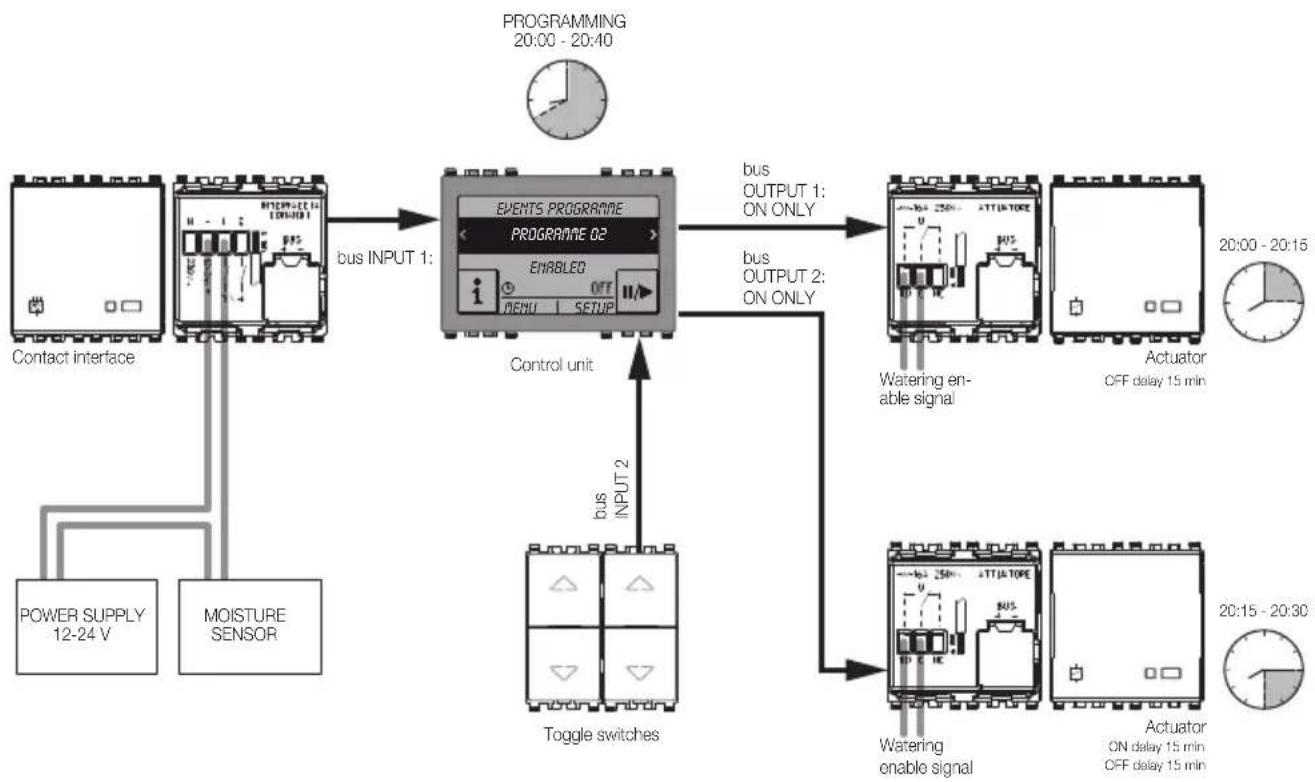
flowchart
graph TD
    A["MOISTURE SENSOR"] -->|POWER SUPPLY 12-24 V| B["Contact interface"]
    B --> C["bus INPUT 1: EVENTS PROGRAMME"]
    C --> D["EVENTS PROGRAMME O2"]
    D --> E[" Bus OUTPUT 1: ON ONLY"]
    D --> F[" Bus OUTPUT 2: ON ONLY"]
    E --> G["Actuator OFF delay 15 min"]
    F --> H["Actuator ON delay 15 min OFF delay 15 min"]
    I["Toggle switches"] --> J["bus INPUT 2"]
    K["Power Supply"] --> B
    L["PROGRAMMING 20:00 - 20:40"] --> C
    M["Watering enable signal"] --> N["Actuator OFF delay 15 min"]
    O["Watering enable signal"] --> P["Actuator ON delay 15 min OFF delay 15 min"]
Programming events
6.3.3 Roller shutter automation.
- Desired program: lower all the shutters after 21.00, or when it becomes windy.
Create a scenario that closes all the roller shutters; the scenario should be called up when one of the two required condition occurs.
Create two programs; the first will be a timer program that calls the scenario that closes the shutters at the desired time. The second one will be a program that calls a scenario when there is activation of a command interface connected to a wind sensor and that is configured in an automation group that will be an input for the program.
6.3.4 Load management by time slots.
- Desired program: from 8:00 hours to 12:00 hours and from 13:00 hours to 18:00 hours, two load control groups are to be disabled by load control module 01455
- Time program: a timer program is used to enable the groups in time slots: 00:00-8:00, 12:00-13:00 and 18:00-24:00 (select the "Weekly clock" timing).
- Inputs: none
- Outputs: select the two groups of the load control system that are to be controlled, then select Pulse ON as the output message.
Integration of the presence detectors
7. Integration of the presence detectors.
The passive infrared presence detectors (Eikon 20485-20486, Arké 19485-19486, Idea 16935 and Plana 14485 or wall-mounting 01828), the dual technology detectors (Eikon 20487, Arké 19487, Idea 16937 and Plana 14487) and the contacts interfaces (Eikon 20490.1-20491, Arké 19490.1-19491, Idea 16940.1-16941 and Plana 14490.1-14491) can be installed in the lighting control system and configured from the control panel.
The presence detectors have the Brightness threshold parameter that by default is set to 100 (maximum value); the value will be lowered depending on the brightness of the environment in which the detector is installed (for very bright environments the brightness threshold will be set to 0).
Duration of actuation (default value 30 s): used, with the system OFF, to repeat the command message for the associated actuator. In practice, after commanding the actuator, the detector checks whether there are any additional movements for a period of time equal to the duration of actuation and, if this has occurred, at the end of this time a new message will be sent to the actuator irrespective of the brightness setting.
When the sensors detect a presence and the brightness is suitable, or when the contacts of the contact interfaces are opened, the parameters of these devices are managed by the control unit in the group (zone) in which they are configured.
Diagnostics and maintenance
8. Diagnostics and maintenance.
8.1 Diagnostics and replacement of devices.
This sections describes the procedures for checking the device functions and how to replace them if necessary.
Setup → Diagnostics → Device diagnostics
The control unit starts a scanning procedure for monitoring the operation of all the configured devices; if they all work the No device failure message is displayed.
If any faulty devices are found, they will be shown on the control unit display; on touching the desired device the control unit will ask whether to replace or remove this device.
Select Renew device to go ahead and replace it or Remove device to delete it.
Confirm by touching Yes.
When making a replacement, if a new device without a configuration is used, the control unit displays an error message; in this case proceed as illustrated in par. 4.5.8
Press the configuration push-button for the New device, after a few seconds the control unit confirms the replacement.
IMPORTANT
Follow the control unit instructions for replacing the faulty part.
At the end of the operation the control unit signals the result; in case of error the display shows the cause that generated it and the solution to implement.
Warning:
When a device is replaced, all the parameters of the replaced device are restored to the new device, as these parameters are also stored on the control unit. The only exception to this is the values stored in the actuators, and the data related to scenarios.
To recreate the scenario as it was before replacement of the device, proceed as follows:
- call the scenario, so that all actuators involved go into the statuses stored in the scenario;
- place the device in the position desired for the scenario;
- save the scenario in the control unit again, as described in paragraph 6.5 "Saving a scenario", checking that the actuators are in the desired position.
N.B.
- It is not possible to renew the infrared receiver (Eikon 20516, Arké 19516, Idea 16956; Plana 14516) via the diagnostics menu; after identifying the faulty device it is then necessary to remove it and reconfigure the replacement receiver as if it were a new device and finally re-associating the buttons of the remote control.
- If replacing an actuator with relay output (Eikon 20535, Arké 19535, Idea 16975; Plana 14535) associated with the Load Control function, it is necessary from the control unit to force the new actuator ON and then bring it back to the desired operating condition.
- If replacing a thermostat via the Diagnostics menu, the control unit resets it in Local mode and in the OFF status.
Diagnostics and maintenance
8.2 Remote communications management.
8.2.1 Remote control.
To enable or disable remote control through the TP interface/telephone communicator 01848, follow the procedure below:
Setup → Diagnostics → Remote Diagnostics
Select Enabled or Disabled and confirm with Save.
To manage the communications, refer to the instruction sheet for the TP interface/telephone communicator 01848 or the instructions manual of the communicator 01942.
It is then possible to run system diagnostics with the GSM communicator that will inform the user about the number and type of faulty devices with the respective physical address.
The remote diagnostics can be run for a maximum number of 8 control units provided that the 8 systems belonging to them (one for each control unit) are connected to a BUS via the appropriate Routers and in at least one of these there is a GSM communicator.
To perform this operation, keep meticulously to the procedures described in the instructions manual of the GSM communicators 01941, 01942 and interface 01848 (that must be combined with 01941).
8.3 Information on the control unit and system.
The procedure is as follows:
Setup → Information
Then select the information that you want to view:
- System information: HW version, SW version, etc.
- System status: Clock ok, etc.
- Database occupation: Devices n/255, Groups n/480, etc.
Installation rules - Compliance with regulations
9. Installation rules.
Installation should be carried out by qualified personnel in compliance with the current regulations regarding the installation of electrical equipment in the country where the products are installed.
The article must be installed only in a SELV environment.
10. Regulatory compliance.
LV directive
EMC directive
Standard 50428
- Other devices in the system: see the relevant instructions sheet.

WEEE - Information for users
If the crossed-out bin symbol appears on the equipment or packaging, this means the product must not be included with other general waste at the end of its working life. The user must take the worn product to a sorted waste center, or return it to the retailer when purchasing a new one. Products for disposal can be consigned free of charge (without any new purchase obligation) to retailers with a sales area of at least 400 m², if they measure less than 25 cm. An efficient sorted waste collection for the environmentally friendly disposal of the used device, or its subsequent recycling, helps avoid the potential negative effects on the environment and people's health, and encourages the re-use and/or recycling of the construction materials.
11. Supplementary declarations made by the manufacturer.
- The By-me control unit meets the prescriptions of the EN 50130-4 and EN 50090-2-2 standards.
- Operating temperature: -5^ - +45^ (class 3K5).
Section
Home automation control equipment
Index
- General features.... 80
- Devices and functions 81
- Configuration on the controller 83
3.1 Functional unit selection and configuration.... 83
3.2 Devices and their functional units 84
3.2.1 Configuration of art 01480 and 01485 85
3.2.2 Configuration of art 01481 and 01486 86
3.2.3 Configuration of art 01482 and 01487 87
3.3 Setting/changing the parameters 89
3.3.1 Functional units and their parameters 89
Presentation of the system
1. General features
The new home automation control equipment represents the evolution of previous By-me control devices, offering new functions combined with an optimized range to guarantee flexibility and easy installation.
The devices can be used transversely in By-me systems (managed via the control panel or EasyTool Professional), or in Plug&Play systems or in integrated systems.
The new home automation control equipment is characterised by:
- restyled aesthetics and RGB backlighting (on Eikon and Arkè the symbols are backlit);
- more control functions available (double the functions of previous By-me units);
• management of short, long and timed button presses; - preprogrammed for use in Plug&Play mode, in combination with the articles compatible with this feature (command pre-configuration and actuator with set scenarios);
- single code for the three series, Eikon, Arkè and Plana (the half buttons of the chosen residential series are then mounted on the device);
- three types of device (with buttons, with buttons and relay actuator, with buttons and roller shutter actuator);
- two types of modularity (2 and 3 modules):
- 4 activations for 2-module devices (4 pushbuttons);
- 6 activations for 3-module devices (6 pushbuttons);
- RGB LED with adjustable brightness (location in the dark/night function), colour coordinated with the thermostats;
- reduced dimensions of flush mounting box.
Devices and functions
2. Devices and functions
The home automation commands are as follows:
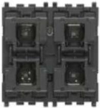 | 01480 - Home automation control module with four pushbuttons, RGB LED location in the dark with brightness control, to be completed with interchangeable half-buttons: 1 or 2 module Eikon, 2 module Arké or Plana. |
 | 01481 - Home automation control module with four push-buttons and actuator with change-over relay output 16 A 120-240 V~ 50/60 Hz, RGB LED location in the dark with brightness control, to be completed with interchangeable half-buttons: 1 or 2 module Eikon, 2 module Arké or Plana. |
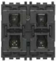 | 01482 - Home automation control module with four pushbuttons and actuator for 1 roller shutter with slat tilt function with change-over relay output for cos ø motor 0.6 2 A 120-240 V~ 50/60 Hz, RGB LED location in the dark with brightness control, to be completed with interchangeable half-buttons: 1 or 2 module Eikon, 2 module Arké or Plana. |
 | 01485 - Home automation control module with six push-buttons, RGB LED location in the dark with brightness control, to be completed with interchangeable half-buttons: 1 or 2 module Eikon, 3 module Arké or Plana. |
Devices and functions

natural_image
Close-up of a black industrial control panel with multiple square modules and mounting brackets (no visible text or symbols)
natural_image
Pure electrical circuit lines without any symbols01486 - Home automation control module with six push-buttons and actuator with change-over relay output 16 A 120-240 V\~ 50/60 Hz, RGB LED location in the dark with brightness control, to be completed with interchangeable half-buttons: 1 or 2 module Eikon, 3 module Arké or Plana.
01487 - Home automation control module with six push-buttons and actuator for 1 roller shutter with slat tilt function with change-over relay output for cos ø motor 0.6 2 A 120-240 V\~ 50/60 Hz, RGB LED location in the dark with brightness control, to be completed with interchangeable half-buttons: 1 or 2 module Eikon, 3 module Arké or Plana.
Configuration on the control unit
3. Configuration on the control unit
The main task to perform in order to configure the home automation control devices on the control panel is to create functional groups (sets of functional units that need to work together) to which they are assigned.
The procedure to be carried out for each new group is as follows:
Setup → Configuration → Groups
Home automation → Create group → Add
Create the selected group:
- Index of new group that identifies the number of the group in the list of all the configured ones; tap Next to confirm.
- New group name selecting, from among the names offered by a pre-set list, both the name of the group and the zone of application (necessary to distinguish between rooms and functions with the same name).
Lastly, proceed to save the name of the group by touching Save.
If the operation has been carried out correctly the control unit will show Operation completed successfully
By selecting the desired group it is possible to view the information related to the group such as the address and number of devices, the devices that may already be linked and to delete the group (Remove Group menu).
3.1 Functional unit selection and configuration.
To configure the various functional units within a group, proceed as follows:
- Tap Setup → Configuration → Groups
- Select the name of the group to which you want to add the functional unit to be configured.
- Once you have chosen the group, tap Associated devices → Add; the procedure is started on the control unit.
- Select the functional unit that you wish to include in the group (as subsequently indicated in the description of each device).
- The device indicates that configuration is in progress by means of a red LED, which goes off when configuration is complete.
- The control unit indicates the functional unit that has just been configured.
- Proceed with the configuration of other functional units by repeating point 4 or tap Backto exit.
IMPORTANT: The scenes have a group depth of 4; this means that the same functional unit can be enrolled in at most 4 scenes.
During the scenario saving procedure, the onboard LEDs of devices 01480, 01481, 01482, 01485, 01486 and 01487 will flash if they are involved in the scenario.
Configuration on the control unit
3.2 Devices and their functional units
Description of the functional units
PUSHBUTTON
- Button: to send ON and OFF messages over the bus as described in the "pushbutton behaviour" parameter.
- Dimmer control: to control dimmer actuators.
- Roller shutter control: to control the functional unit for roller shutters with no slats (as each command is the opposite of the previous one, at each long press of the button, the movement of the roller shutter changes between up and down).
- Timer controlled command only*: to activate timer control
- Timer controlled* and ON/OFF command: to activate a timer controlled command or send an ON/OFF command, depending how the button is pressed (for example, short press for timed control and long press for ON/OFF)
- scenario control: to call up and save a scenario.
- Send value: to send the value selected during configuration when the button is pressed.
- Sleep: to call up the sleep function in the speaker system.
- Audio monitoring: audio monitoring control (if associated with a microphone module).
ROCKER SWITCH
- Rocker switch: to send ON and OFF commands.
- Dimmer control: to control dimmer actuators.
- Roller shutter control: to control the roller shutter functional unit (normal or with slats).
- Timer controlled command only*: to activate timer control
- Timer controlled* and ON/OFF command: to activate a timer controlled command or send an ON/OFF command, depending how the button is pressed (for example, short press for timed control and long press for ON/OFF)
• Volume OnOff: on/off and volume control for the speaker system. - Sleep: to call up the sleep function in the speaker system.
- Ch+/Track+: ch+/track+ control for speaker system.
ACTUATOR
- Actuator: for control of a lighting actuator.
Receives the following command requests: load on/off, scenario save and recall. - Timer controlled actuator: for control and also timer control of a lighting actuator.
Receives the following command requests: timer controlled load on/off, load on/off, scenario save and recall.
ROLLER SHUTTER ACTUATOR
- Roller shutter actuator: to control the roller shutter.
- Blind: to control the roller shutter + slats
These functional units receive the following command requests: open/close roller shutters, rotate slats, set roller shutter height and slat rotation values, scenario save and recall, forcing by logic module.
* Configuration of the timer controlled command is only possible if there is at least one actuator in the group with the timer control function.
Configuration on the control unit
| Article | |||
| Functional unit | Home automation control unit with pushbuttons art. 01480-01485 | Home automation control unit with pushbuttons and relay actuator with switching output art. 01481-01486 | Home automation control unit with pushbuttons and actuator for 1 roller shutter with slat control art. 01482-01487 |
| Actuator | √ | ||
| Roller shutter actuator | √ | ||
| Blinds actuator | √ | ||
| Timer controlled actuator | √ | ||
| Pushbutton | √ √ √ | ||
| Timer controlled command only | √ | √ | |
| Timer controlled and ON/OFF command | √ | √ | |
| Scenario control | √ √ √ | ||
| Rocker switch | √ √ √ | ||
| Dimmer control pushbutton and rocker switch, volume On/Off | √ √ √ | ||
| Send value | √ √ √ | ||
| Roller shutter control pushbutton and rocker switch | √ √ √ | ||
| ch+/track+ | √ √ √ | ||
| Sleep pushbutton and rocker switch, audio monitoring pushbutton | √ √ √ | ||
IMPORTANT:
• Each key can be configured as a pushbutton and the keys of the same device can be grouped together to act as a rocker switch.
- The pushbutton and rocker switch functional units have a group depth of 1 (that is, they can belong to one group only).
3.2.1 Configuration of art 01480 and 01485
The functional units that the device makes available are as follows:
- 4 pushbuttons or 2 rocker switches for art. 01480
- 6 pushbuttons or 3 rocker switches for art. 01485
FUNCTIONAL UNITS
- For the pushbutton logic function, the following functional units can be selected:
- pushbutton
- dimmer control
- roller shutter control
- timer controlled command only*
- timer controlled* and ON/OFF command
Configuration on the control unit
- roller shutter control
- scenario control
- send value
- sleep (command for speaker system)
- audio monitoring (command for speaker system)
- For the rocker switch logic function, the following functional units can be selected:
- rocker switch
- dimmer control
- roller shutter control
- timer controlled command only*
- timer controlled* and ON/OFF command
- Volume On/Off (volume control for speaker system)
- sleep (command for speaker system)
- ch+/track+ (command for speaker system)
* Configuration of the timer controlled command is only possible if there is at least one actuator in the group with the timer control function.
Selecting the functional unit to be configured:
After pressing the configuration button, before the red LED lights up (4 s.), choose one of the following options:
- Short press the key you wish to configure as a pushbutton; the LED will light up white to confirm the selection made.
- Simultaneously short press the two keys you wish to configure as rocker switches; the LEDs will light up white to confirm the selection made.
The LED/s of the pushbutton or rocker switch light up white to highlight the functional unit you are selecting.
After a pause of a few seconds, the device enters configuration mode for the selected functional unit and the start of configuration is signalled by the red LED. At the end of this operation the red LED will go out.
SCENARIOS.
The pushbuttons and rocker switches can belong to multiple scenarios, and, for each scenario, save the status of the associated LEDs; during the scenario identification stage, the LEDs will flash if the group they belong to is involved in that particular scenario.
3.2.2 Configuration of art 01481 and 01486
The functional units that the device makes available are as follows:
- 4 pushbuttons or 2 rocker switches + relay actuator for art. 01481
- 6 pushbuttons or 3 rocker switches + relay actuator for art. 01486
FUNCTIONAL UNITS
- For the pushbutton logic function, the following functional units can be selected:
- pushbutton
- dimmer control
- roller shutter control
- timer controlled command only*
- timer controlled* and ON/OFF command
- scenario control
Configuration on the control unit
- send value
- sleep (command for speaker system)
- audio monitoring (command for speaker system)
- For the rocker switch logic function, the following functional units can be selected:
- rocker switch
- dimmer control
- roller shutter control
- timer controlled command only*
- timer controlled* and ON/OFF command
- Volume On/Off (volume control for speaker system)
- sleep (command for speaker system)
- ch+/track+ (command for speaker system)
- For the actuator output, the following functional units can be selected:
- actuator
- timer controlled actuator
* Configuration of the timer controlled command is only possible if there is at least one actuator in the group with the timer control function.
Selecting the functional unit to be configured:
After pressing the configuration button, before the red LED lights up (4 s.), choose one of the following options:
- Short press the key you wish to configure as a pushbutton; the LED will light up white to confirm the selection made.
- Simultaneously short press the two keys you wish to configure as rocker switches; the LEDs will light up white to confirm the selection made.
- Pressing just the configuration button of the device alone automatically selects the actuator function unit.
The LED/s of the pushbutton or rocker switch light up white to highlight the functional unit you are selecting.
After a pause of a few seconds, the device enters configuration mode for the selected functional unit and the start of configuration is signalled by the red LED. At the end of this operation the red LED will go out.
SCENARIOS.
The pushbuttons and rocker switches can belong to multiple scenarios, and, for each scenario, save the status of the associated LEDs; during the scenario identification stage, the LEDs will flash if the group they belong to is involved in that particular scenario. The actuator can belong to multiple scenarios and, for each one of them, save the status (ON or OFF) to retrieve when activating the scenario itself.
3.2.3 Configuration of art 01482 and 01487
The functional units that the device makes available are as follows:
- 4 pushbuttons or 2 rocker switches + roller shutter and slat actuator for art. 01482
- 6 pushbuttons or 3 rocker switches + roller shutter and slat actuator for art. 01487
- 4 pushbuttons or 2 rocker switches + roller shutter and slat actuator for art. 01482 - 6 pushbuttons or 3 rocker switches + roller shutter and slat actuator for art. 01487
FUNCTIONAL UNITS
- For the pushbutton logic function, the following functional units can be selected:
- pushbutton
- dimmer control
- roller shutter control
- timer controlled command only*
- pushbutton - dimmer control - roller shutter control - timer controlled command only*
Configuration on the control unit
- timer controlled* and ON/OFF command
- scenario control
- send value
- sleep (command for speaker system)
- audio monitoring (command for speaker system)
- For the rocker switch logic function, the following functional units can be selected:
- rocker switch
- dimmer control
- roller shutter control
- timer controlled command only*
- timer controlled* and ON/OFF command
- Volume On/Off (volume control for speaker system)
- sleep (command for speaker system)
- ch+/track+ (command for speaker system)
- For the roller shutter, one of the following functional units can be selected:
Caution: after configuration you need to open and close each roller shutter completely to carry out the calibration process.
* Configuration of the timer controlled command is only possible if there is at least one actuator in the group with the timer control function.
Selecting the functional unit to be configured:
After pressing the configuration button, before the red LED lights up (4 s.), choose one of the following options:
- Short press the key you wish to configure as a pushbutton; the LED will light up white to confirm the selection made.
- Simultaneously short press the two keys you wish to configure as rocker switches; the LEDs will light up white to confirm the selection made.
- Pressing just the configuration button of the device alone automatically selects the roller shutter actuator function unit.
The LED/s of the pushbutton or rocker switch light up white to highlight the functional unit you are selecting.
After a pause of a few seconds, the device enters configuration mode for the selected functional unit and the start of configuration is signalled by the red LED. At the end of this operation the red LED will go out.
SCENARIOS.
The pushbuttons and rocker switches can belong to multiple scenarios and, for each scenario, save the status of the associated LEDs.
During the scenario identification stage, the LEDs flash if the group to which they belong is involved in the scenario.
The roller shutter actuator can save and recall the height of the roller shutter.
The blinds actuator can save and recall the height of the roller shutter and the angle of the slats.
Configuration on the control unit
3.3 Setting/changing the parameters.
Device parameters can be set and/or modified in order to customize operation to adapt the system to the various installation requirements.
Setup → Configuration → Groups → Select the group by scrolling through the list → Associated devices → Select the functional unit by scrolling through the list → Device parameters
3.3.1 Functional units and their parameters
Description of the parameters
ACTUATOR
- On and off delay (they are delay times that can be set for actuating the On and Off request): from 0 s to 12 h with default value 0 s.
- ON time duration for one-position stable operation (this is the activation time for one-position stable operation): from 1 s to 12 h with default value 30 s.
- Warning time (this is a time that is added to the activation time of the one-position stable actuator. At the end of the activation time the relay switches off for 0.5 s and then switches back on for the warning time): from 0 s to 12 h with default value 0 s.
- Output status at power on and output status at power down (this enables setting the actuator when switching off and upon restoring power respectively): ON/OFF/Unchanged with default value "Unchanged".
Note: If the value "unchanged" is selected for the parameter "output status on power on", on power on, the actuator will return to its position immediately prior to the power down, independently of forcing (ON or OFF) required on power down.
- Operation (this enables setting the operation of the actuator): one-position stable/two-position stable with default value "two-position stable".
- Status at rest of relay contact: normally open (default value) or normally closed
- Feedback group: this allows you to select the group on which to send the actuator status, so as to align the LEDs of the commands.
ROLLER SHUTTER AND BLINDS ACTUATOR
- Up and down time (these are the roller shutter up and down times): 10 s to 1 h with default value 180 s.
- Full slat rotation time: from 500 ms to 5 s with default value 2 s.
- Behaviour at power on (this enables setting whether when power is restored the roller shutter opens, closes, remains in the current position or you can choose the height of the roller shutter and the tilt of the slats): all down, all up, no action, default position. Default value "no action".
- Position of the roller shutter at power on (enables setting the position of the roller shutter when power is restored): from 0 to 100% with default value 50% .
- Scenario recall execution delay (this enables delaying execution of the command so as not to actuate all the roller shutters at once): from 0 s to 250 s with default value 0 s.
- Command execution delay: from 0 s to 250 s with default value 0 s.
- Tilt of the slats at power on (enables setting the position of the slat when power is restored): from 0 to 100% with default value 50% .
- Position on forcing (this enables setting the behaviour of the roller shutter upon the forcing request): all down, all up, fixed, preset position with default value "fixed." It is necessary to observe the value set by the "roller shutter position on forcing" and "slat tilt on forcing" parameters.
Configuration on the control unit
- Position on end of forcing (this enables setting the behaviour of the roller shutter at the end of forcing): all down, all up, fixed, preset position with default value "fixed." It is necessary to observe the value set by the "roller shutter position on forcing" and "slat tilt on forcing" parameters; it returns to the previous value with the request for forcing.
- Roller shutter position on forcing (can be used in the "position on forcing" and "position on end of forcing" parameters): from 0 to 100% with default value 50% .
- Slat tilt on forcing (can be used in the "position on forcing" and "position on end of forcing" parameters): from 0 to 100% with default value 50% .
PUSHBUTTON AND ROCKER SWITCH
- Pushbutton behaviour: normal pushbutton ON on pressing the key, OFF on release, inverted pushbutton OFF on pressing, ON on release, toggle on the rising edge, toggle on the falling edge, toggle on both edges, ON only ON on pressing, only OFF OFF on pressing. Default value "Toggle on the rising edge".
- Enable scenario saving (this parameter is for the scenario recall button that allows you to choose whether, with a long press, the pushbutton sends a request to save the current scenario). Default value "Disabled".
- Long press time: from 0.5 s to 30 s with default value 0.5 s.
- Short/long press behaviour: normal or reversed with default value "normal." This parameter is useful also for actuators with the timer control function to invert the two ON/OFF and timer controlled commands.
- Up/Down orientation:
- (ON on pressing the upper button and OFF on pressing the lower button or vice versa).
- valid only for the dimmer control (ON and UP on pressing the upper button and OFF and DOWN when pressing the lower button or vice versa).
- valid only for the roller shutter pushbutton (roller shutter UP on long press of upper button and roller shutter DOWN on long press of lower button or vice versa).
-
ch+ on pressing the upper button and track+ on pressing the lower button or vice versa.
-
Output value (the value selected with this parameter is sent when the pushbutton is pressed): from 0 to 100% with default value 0%.
- Blind behaviour (valid for blind pushbutton and rocker switch): parameter allows you to choose whether or not on release from a long press the stop command is sent to the roller shutter.
- LED colour: allows you to select the colour of each individual LED from a predefined list or to set the desired RGB coordinate directly.
- LED brightness ON and OFF
- For the pushbutton, for the dimmer control pushbutton, for the sleep and audio monitoring pushbutton: possibility to set the brightness level of the LEDs when the associated load is activated or deactivated (high brightness, medium brightness, low brightness, off)
- For the roller shutter pushbutton, for the scenario control pushbutton and for send value pushbutton: on pressing the button the LED illuminates for 3 s at the brightness level set with the parameter "LED on brightness".
- Upper LED on brightness, upper LED off brightness, lower LED on brightness, lower LED off brightness,
- For the rocker switch, for the dimmer control rocker switch, for the sleep and ch+/track+ rocker switch: possibility to set the brightness levels of both LEDs when the associated load is activated or deactivated (high brightness, medium brightness, low brightness, off).
- For the blind rocker switch: on pressing the button, the LEDS of the functional unit illuminate for 3 s at the brightness level set with the parameter "upper LED on brightness" and "lower LED on brightness".
Configuration on the control unit
| Functional Units | |||||||||||
| Parameter Pushbutton | Dimmer control push-button | Roller shutter control push-button | Timer controlled-push-button | Scenario control | Send value | Sleep and audio monitoring push-button | Rocker switch, sleep and ch+/track+ rocker switch | Dimmer control rocker switch | Roller shutter control rocker switch | Timer controlled rocker switch | |
| Pushbutton behaviour | √ | ||||||||||
| Long/short press behaviour | √ | √ | |||||||||
| Enable scenario saving | √ | ||||||||||
| Roller shutter long press | √ | √ | |||||||||
| LED ON brightness | √ √ | √ √ | √ √ √ | ||||||||
| LED OFF brightness | √ √ | √ √ | √ √ √ | ||||||||
| Upper LED ON brightness | √ | √ √ | √ | ||||||||
| Upper LED OFF brightness | √ √ | √ √ | |||||||||
| Lower LED ON brightness | √ √ | √ √ | |||||||||
| Lower LED OFF brightness | √ √ | √ √ | |||||||||
| Long press time | √ √ | √ √ | √ √ | √ | |||||||
| Output value | √ | ||||||||||
| Rocker switch orientation | √ √ | √ √ | |||||||||
| LED colour | √ √ | √ √ | √ √ √ | √ √ | √ √ | ||||||
Configuration on the control unit
| Functional Units | ||||
| Parameter Actuator | Timer controlled actuator | Roller shutter actuator | Blinds actuator | |
| On and off delay | √ | √ | ||
| On duration for one-position stable operation | √ | √ | ||
| Warning period | √ | √ | ||
| Output status at power on and at power down | √ | √ | ||
| Operation | √ | |||
| Default status | √ | √ | ||
| Up and down time | √ | √ | ||
| Full slat rotation time | √ | |||
| Scenario command execution delay | √ | √ | ||
| Command execution delay | √ | √ | ||
| Behaviour at power ON | √ | √ | ||
| Roller shutter position at power on | √ | √ | ||
| Slat angle at power on | √ | |||
| Position on forcing | √ | √ | ||
| Position on end of forcing | √ | √ | ||
| Roller shutter position on forcing | √ | √ | ||
| Slat angle on forcing | √ | |||
Section
Speaker system
Table of Contents
1. General characteristics of the system.... 95
2. Devices and functions 96
2.1 Transmitter devices.... 96
2.2 Receiver devices....97
2.3 Acoustic speakers.... 97
2.4 Accessory modules 98
3. Topology and installation rules 99
3.1 Installation topology 99
3.2 Installation rules 101
4. System constraints.... 101
4.1 Distances 101
4.2 Absorption of the devices and sizing of the system 105
4.3 Number of devices 106
5. Functionality 107
5.1 Control buttons.... 108
5.2 Zone priority 108
5.3 Microphone call.... 108
5.4 Baby-Control function.... 109
5.5 Audio monitoring function.... 109
5.6 Alarm clock function 109
5.7 Timed shutdown function (Sleep) 109
5.8 Silencing function 109
5.9 Voice communications function.... 109
5.10. Scenarios 109
6. System components.... 110
6.1 Control unit 110
6.2 Audio input with 2 RCA connectors 111
6.3 FM radio tuner 113
6.4 Home automation control module with four pushbuttons 115
6.5 Stereo amplifier with 2 outputs 117
6.6 Docking Station for iPod/iPhone 119
6.7 Bluetooth® technology interface for home automation 121
6.8 Microphone module 123
6.9 IR control module 126
6.10 Line decoupler for Bus/speaker system for By-me power supply 131
6.11 Shunt for By-me control devices.... 131
6.12 Branch shunt for speaker system devices.... 131
7. Group/zone definition.... 132
7.1 Audio groups management.... 132
7.2 Audio zones management 132
7.3 Audio zone settings 132
7.4 Alarm clock function 134
7.5 Viewing audio zones 134
7.6 Docking station management 137
7.7 Details menu of the RCA source associated with the IR interface IR 20586-19586-14586.....140
7.8 Adding devices to a group 141
7.9 Removing devices from a group 141
7.10 Editing device parameters.... 141
8. Types of system 144
8.1 Audio zones with receiver modules.... 144
8.2 Audio zones with voice call function 145
8.3 Audio zones with Baby Control function 146
8.4 Audio zones with audio monitoring function 147
8.5 Audio zones with voice communication function.... 148
8.6 Audio zones with central switch-off.... 149
8.7 Amplifier with Bluetooth receiver not connected to the bus and speaker system 150
8.8 Bluetooth interface connected to the speaker system bus 151
8.9 Bluetooth interface connected to the speaker system bus and third-party amplifier ..... 152
9. Glossary.... 153
Presentation of the system
1. General characteristics of the system
The By-me speaker system enables creating systems able to transmit up to 4 audio sources in different rooms at the same time with high signal quality (CD quality).
Thanks to the various system devices, integration with all the existing By-me controls and the range of coordinated speakers, it is possible to create mono or multi-channel systems completely integrated in the By-me system.
In the various rooms there is total freedom of choice and control and it is possible, thanks to the multi-channels, to transmit different music in different rooms.
The possibility of free distribution of the transmitter and receiver nodes and of the commands keeps the wiring simple allowing perfect integration with the controls and actuators of the home automation system.
The range has been extended, both to manage more available audio sources (new Bluetooth® technology interface and the possibility to add an unlimited number of local sources) and to increase the power handling capacity (commands with preamplified outputs and new flush-mounting amplifier).
The performance, numerous functions, installation flexibility and above all the quality of the sound enable using the system both in the residential sector (from apartments to villas) and in the tertiary sector (health centres, shops, cafés, restaurants, supermarkets).
The main characteristics can be summed up in the following points:
-
2-wire system (uses the By-me BUS cable art.01840.E.B) with in-out linear wiring that enables perfect integration with the By-me automation devices (that can be connected to the "audio" branch through a special branch shunt for By-me devices 01903 or through the special terminal on all the devices of the speaker system).
-
Possibility of using the By-me controls (buttons, touchscreen and also the ones connected to the automation line) for system control (switching on/off, volume adjustment, source selection, song selection or radio station, etc.).
-
Distributed architecture (therefore with no central node that requires star wiring) that enables installing transmitters and receivers at any point in the system.
-
4 simultaneous stereo channels, with CD audio quality.
-
Up to 30 independent audio zones.
-
Possibility of using the BUS as an FM antenna (in this case the auxiliary external antenna is not necessary).
-
Possibility to connect higher power amplifiers thanks to the LINE OUT output (art. 20590-19590-14590 or third party amplifiers).
-
In addition to the RCA inputs, the FM tuner and docking station is now available with Bluetooth technology interface.
-
Possibility of programming the maximum audio levels for each zone.
-
Possibility of making microphone calls.
-
Audio monitoring function.
-
Baby control function.
-
Integration with the scenarios and events programmes of the By-me system (for instance radio alarm function).
Devices and functions
2. Devices and functions
The speaker system is composed of the following categories of devices:
• Transmitter devices
- Receiver devices
• Acoustic speakers
- Accessory modules
2.1 Transmitter devices
The transmitter devices enable transmitting the sound coming from a sound source (e.g. HiFi system, CD player, portable MP3 players, etc..) to the system receivers.
Each transmitter configured in the system occupies one of the 4 available channels and can be connected to any point of the system.
 | 20582-19582-14582: Input module with 2 RCA connectors.Galvanic decoupling of the audio inputs in relation to the By-me bus.Flush-mounting 2M mechanism. |
 | 01900: FM radio tuner with RDS on 2 DIN modules.Managed via By-me control units and touchscreen, displaying RDS info (tuning, station, song, etc..). 8 tuning memories available.Possibility of using internal antenna (BUS) or external antenna with coaxial connector (type F). |
 | 20585-19585-14585: Docking station for iPod/iPhone.Flush-mounting 2M mechanism with docking station for iPod/iPhone.Capable of controlling the iPod/iPhone (play/pause, skip +/-). Capable of charging the iPod/iPhone if connected to the auxiliary power supply 5V, 1A, 2M. |
 | |
 | 20589-19589-14589: Bluetooth® technology interface for home automation, stores up to 8 mobile devices.Flush mounting 2M mechanism. The device is aBluetooth technologyinterface that acts as a transmitter in the By-me speaker system to input the audio from a smartphone or tablet (Android, iOS and Windows Phone) on a BUS channel. In addition to transmitting the audio signal to the receiver devices, it can also be used to control the smartphone or tablet remotely by sending commands over the bus. |
Devices and functions
 | 20586-19586-14586: Microphone call moduleCall enabling calling different services available (2M flush mounting). Front buttons for activating the call, general or selective, built-in microphone. |
2.2 Receiver devices
The receiver devices enable listening to the audio transmitted through one of the channels in the system. These devices are also equipped with a high quality audio amplifier that enables direct connection to the acoustic speakers.
 | 01483: Home automation control module with four pushbuttons, 1 LINE OUT output, RGB LED location in the dark with brightness control, to be completed with interchangeable half-buttons: 1 or 2 module Eikon, 2 module Arké or Plana. |
 | 01484: Home automation control module with four push buttons with 1 + 1 Wrms stereo amplifier, 2x 8 ohm speaker outputs, RGB LED location in the dark with brightness control, to be completed with interchangeable half-buttons: 1 or 2 module Eikon, 2 module Arké or Plana. |
 | 01901: Output module with amplifier 10+10WMechanical /DIN 6M.Power supply 110-230V~, 50-60Hz |
 | 20590-19590-14590: Stereo amplifier 4 + 4 W rms, 2 outputs for 8 Ω speakers with built-in Bluetooth technology receiver, 1 LINE IN input, 12 V SELV power supply - 2 modules. |
2.3 Acoustic speakers
The system has a complete range of acoustic speakers, both flush-mounting and surface-mounting (including versions for ceilings, light walls, etc.).
 | 21588: Flush-mounting passive acoustic speaker 4+4M, 10W 8Ω |
 | 20587: Flush-mounting passive acoustic speaker 3M, 3W 8Ω |
Devices and functions
 | 01906: Passive IP55 acoustic speaker, 30W 8Ω01907: Surface ceiling-mounting passive acoustic speaker, 30W 8Ω |
 | 01908: Surface wall-mounting passive acoustic speaker, 30W 8Ω |
2.4 Accessory modules
The accessory modules are those devices that, while not having any direct use by the user, are needed by the system for its operation or for creating the various possibilities of wiring/construction (see chap. 3 and 4).
 | 01902: Decoupler for By-me power supplyDecoupling module to be used at the By-me power supply output (or at the output of a line coupler).Enclosure/DIN 2M |
 | 01903: Branch shunt module for By-me Automation devicesRetrofit enclosure |
 | 01904: Branch shunt module for speaker system devicesRetrofit enclosure. |
 | 20580-19580-14580: Auxiliary power supply 32VPower supply 110-230V~, 50-60HzOutput 32 Vdc, 3W.Flush-mounting 1M mechanism. |
 | 20584-19584-14584: Control of stereo sources with remote control (not supplied) via cable with IR transmitter (supplied).The device must be associated with an RCA input module. |
Topology and installation rules
3. Topologies and installation rules
The new type of transfer of musical information in digital form over the same BUS where the By-me data packets transit requires some constraints for the wiring and in the construction of the system, while maintaining perfect integration with the By-me home automation system.
To facilitate installation a coloured BUS cable art.01840.E.B (dark blue in colour) has been introduced to identify the part of the system or branches of the bus dedicated to the speaker system easily and with no error.
3.1. Installation topologies
The speaker system lends itself to various constructions according to the needs and dimensions of the system.
Example 1: speaker system on the same logical branch (Area/Line), but with separate wiring.
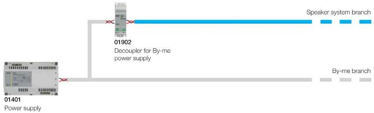
flowchart
graph LR
    A["01401 Power supply"] --> B["01902 Decoupler for By-me power supply"]
    B --> C["Speaker system branch"]
    B --> D["By-me branch"]
In this case the separation is purely with the wiring and not the logic: the speaker system devices and the By-me devices are configured on the same line.
Example 2: dedicated logic branch

flowchart
graph TD
    A["01401 Power supply"] --> B["01845.1 Line coupler"]
    B --> C["01902 01902 01401 Decoupler for By-me power supply"]
    C --> D["01401 Power supply"]
    D --> E["Power supply 01401 and decoupler for By-me power supply"]
    style A fill:#f9f,stroke:#333
    style B fill:#ccf,stroke:#333
    style C fill:#cfc,stroke:#333
    style D fill:#fcc,stroke:#333
    style E fill:#cff,stroke:#333
Topology and installation rules
In this case, the speaker system devices are configured in a different line to the other By-me devices. The second power supply and the dedicated decoupler are optional and must only be included when necessary for reasons of consumption.
Example 3: By-me automation and speaker system on the same branch

flowchart
graph TD
    A["01401 Power supply"] --> B["01902 Decoupler for By-me power supply"]
    B --> C["01483-01484"]
    C --> D["01903"]
    D --> E["01483-01484"]
    E --> F["20582"]
    E --> G["01483-01484"]
    G --> H["20589"]
    B --> I["By-me branch: free wiring"]
    I --> J["01901"]
    I --> K["01901"]
    I --> L["01483-01484"]
    L --> M["01904"]
    M --> N["01483-01484"]
    N --> O["20582"]
    N --> P["01483-01484"]
    P --> Q["01902"]
    Q --> R["01401 Power supply"]
| By-me branch. Free wiring | ||
| Speaker system branch. By-me devices cannot be connected; In-out wiring (linear, not star); Max length 300 m; Max number of speaker system devices: 64. | ||
 | The shunt for the By-me control devices enables creating By-me branches that contain max 10 automation devices. Max no. of shunts 01903=64 | |
 | The speaker system shunt 01904 enables shunting speaker system branches. | |
| [6AWY] | Decoupler for By-me power supply/speaker system. It must be inserted between the power supply and the audio line; none of the By-me devices between the decoupler and the power supply are “seen” by the speaker system. | |
This explains how it is possible to make a completely integrated system with the By-me automation and speaker system devices on the same branch.
System constraints
Warning: By-me devices are not connected directly to the branch of the speaker system (blue branch) but through special shunts or through the devices of the speaker system (that have a special terminal).
3.2 Installation rules
The following installation rules are compulsory in the sections of By-me Bus dedicated to the speaker system:
- Free wiring is not permitted in the sections dedicated to the speaker system, but only the in-out linear type. For shunting it is necessary to use the special branch shunt for the speaker system art.01904.
- No more than 2 branch shunts can be wired per speaker system (art.01904) between a transmitter and a receiver: this is because the branch shunt introduces strong signal attenuation.
- The section of BUS dedicated to the speaker system is separated from the power supply (or from the line coupler if used) by the special "By-me power supply/speaker system decoupler" art.01902.
- In the sections dedicated to the speaker system (dark blue sections) it is possible to connect only the devices of the speaker system: the By-me devices (where applicable) must be connected either through the specific branch shunt for By-me devices (art. 01903, max. 10 By-me devices) or through the dedicated terminal in each speaker system device (branch with max. 3 By-me devices).
- Finally, the devices at the ends of the speaker system branches (at the start and at the end of the blue lines) must be terminated via the special jumpers present in each device. This applies to any device, whether it be a By-me power supply/speaker system decoupler or a normal transmitter or receiver.
4. System constraints
In order to ensure correct system operation and complete functionality, it is necessary to respect constraints to be taken account of in the installation.
4.1 Distances
The following table illustrates the constraints of the system related to the distances between the transmitters and the receivers.
| Maximum distance between a receiver and a transmitter with no intermediate shunts | 300 m See fig. A | |
| Maximum distance between a receiver and a transmitter with 1 intermediate shunt | 200 m See fig. B | |
| Maximum distance between a receiver and a transmitter with 2 intermediate shunts | 100 m See fig. C |
System constraints
A
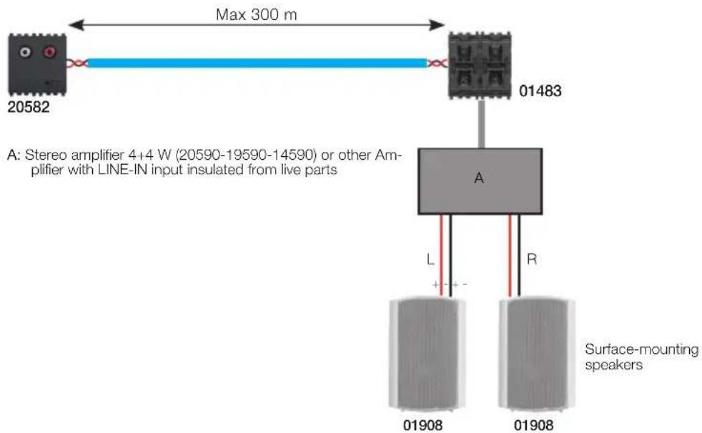
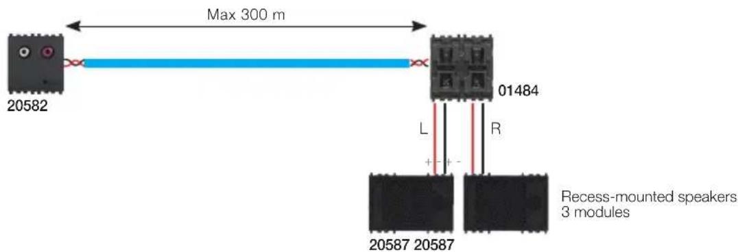
B
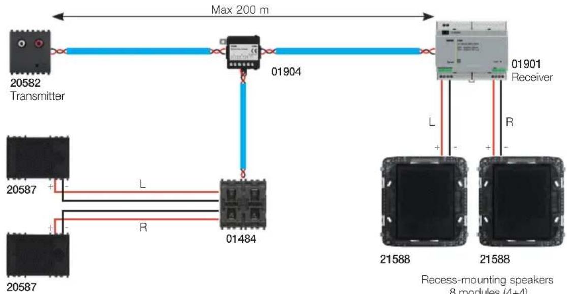
flowchart
graph TD
    A["20582 Transmitter"] --> B["01904"]
    B --> C["01901 Receiver"]
    D["20587"] --> E["01484"]
    F["20587"] --> G["01484"]
    H["L"] --> I["01484"]
    J["R"] --> K["01484"]
    L["L"] --> M["21588"]
    N["R"] --> O["21588"]
    P["Max 200 m"] --> B
    Q["Recess-mounting speakers 8 modules (4+4)"] --> M
    Q --> O
Recess-mounting speakers 3 modules
System constraints
C
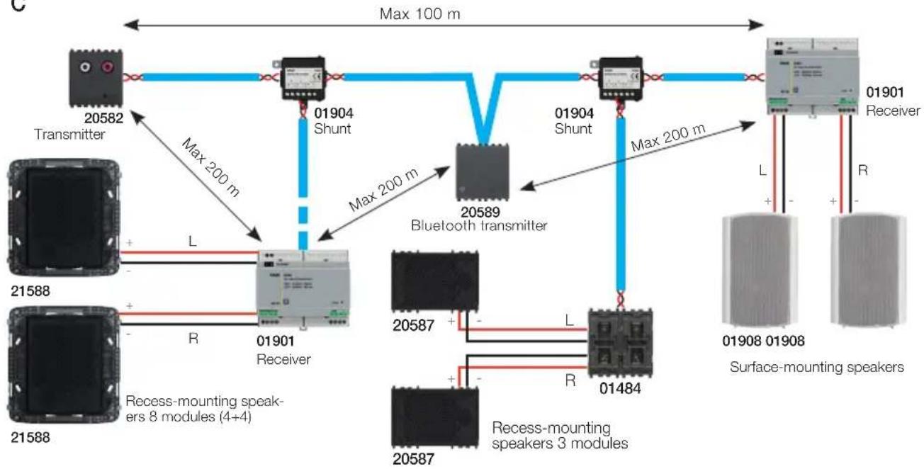
flowchart
graph TD
    A["20582 Transmitter"] -->|Max 200 m| B["01904 Shunt"]
    B -->|Max 200 m| C["20589 Bluetooth transmitter"]
    C -->|Max 200 m| D["01901 Receiver"]
    D -->|L| E["21588 Surface-mounting speakers"]
    D -->|R| F["21588 Recess-mounting speakers 8 modules (4+4)"]
    C --> G["20587 Recess-mounting speakers 3 modules"]
    C --> H["20587 L"]
    C --> I["20587 R"]
    style A fill:#f9f,stroke:#333
    style B fill:#ccf,stroke:#333
    style C fill:#cfc,stroke:#333
    style D fill:#fcc,stroke:#333
    style E fill:#cff,stroke:#333
    style F fill:#ffc,stroke:#333
    style G fill:#fcf,stroke:#333
    style H fill:#cff,stroke:#333
    style I fill:#ffc,stroke:#333
The following table illustrates the constraints of the system related to the distances between the receivers and the speakers.
| Distance between receiver LINE OUT (art. 01483) and power amplifier 10 m See fig. D | ||
| Distance between receiver 1+1W (art. 01484) and speakers 10 m See fig. E | ||
| Distance between receiver 10+10W (art. 01901) and speakers 30 m See fig. F |
D

System constraints
E

Recess-mounting speakers 3 modules
F

Surface wall-mounting speakers 10 W min.
System constraints
4.2 Absorption of the devices and sizing of the system
Since the system is completely integrable with By-me automation and uses the power supplies 01401, the limits of absorption to calculate for each line in the system apply generally: max. 2 By-me power supplies 01401 and therefore max. 2x1280 mA. The speaker system devices have different absorptions than the conventional By-me devices and this must therefore be taken into consideration when sizing the system. The following table, useful for correctly sizing the system, gives the absorptions of the devices.
| Device Absorption Notes | ||
| 20582-19582-14582 TX flush-mounting 2M 2-RCA 35 mA Equivalent to 3 By-me devices | ||
| 01900 TX /DIN with FM radio 35 mA Equivalent to 3 By-me devices | ||
| 20584-19584-14584 IR control for stereo 20 mA Equivalent to 2 By-me device | ||
| 20585-19585-14595 TX docking station for iPod/iPhone | 35 mA | Equivalent to 3 By-me devices |
| 20589-19589-14589 Bluetooth technology Interface | 35 mA | Equivalent to 3 By-me devices |
| 01483 RX with LINE OUT output 35 mA Equivalent to 3 By-me devices | ||
| 01484 RX with amplifier for flush mounting 1+1W (if powered via BUS) | 150 mA max Equivalent to 15 By-me devices | |
| 01484 RX with amplifier for flush mounting 1+1W (if powered via power supply 20580-19580-14580) | 10 mA Equivalent to 2 By-me devices | |
| 01901 RX with amplifier 10+10W /DIN, 230V ac 20 mA Equivalent to 2 By-me devices | ||
| 20586-19586-14586 Microphone call module 35 mA Equivalent to 3 By-me devices | ||
WARNING: The absorptions given in the table are to be considered only for the audio devices and do not take account of any other automation devices that may be connected to the By-me branch shunting terminal. The high absorption of the receiver 1+1W (if powered directly by the BUS and not through the auxiliary power supply) has limits also as regards its distance from the system power supply, especially if it is present in a number of points on the same branch.
| With 1 receiver 01484 powered by Bus 300 m | |
| With 2 receivers 01484 powered by Bus 150 m | |
| With 3 receivers 01484 powered by Bus 100 m | |
| With 4 receivers 01484 powered by Bus 75 m |
These data refer to the case in which there is a number of receivers 1+1W (art. 01484) on the same branch and on the same side in relation to the By-me power supply 01401 (see figure below).
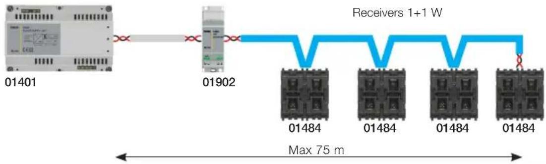
System constraints
Whereas, in the case in which the devices are always on opposite branches in relation to the By-me power supply, the distance must be calculated in relation to the power supply counting the devices on the branch.

flowchart
graph TD
    A["Device 01401"] --> B["Receivers 1+1 W"]
    A --> C["01484 0148401484 01484"]
    A --> D["01902"]
    B --> E["Max 150 m Max 150 m"]
    C --> E
    D --> E
    E --> F["Receivers 1+1 W"]
Therefore depending on the number of transmitters and receivers (and on their type) it is possible to calculate the absorption of the system and therefore the number of power supplies necessary, that in any case can be at most 2. If you want to install numerous receivers 1+1W (art. 01484) it is advisable to use the auxiliary power supplies 20580-19580-14580.
4.3 Number of devices
As regards the number of devices that can be used on the branches of the speaker system the following restrictions apply:
| Description Number Notes | ||
| Maximum No. of inputs (transmitters) 4 | 4 stereo channels | |
| Maximum No. of “Audio” devices (inputs, outputs, accessories) | 64 Limit fixed by the input impedance of the “audio” nodes. | |
| No. of receivers not powered by Bus | 64 - no. of inputs - no. of accessories (shunts, decouplers, etc). | Total: max 64 devices (transmitters, receivers, accessories). Each receiver can choose the audio channel from the 4 available ones |
| No. of receivers powered by BUS 01484 | A receiver powered via BUS consumes as much as 15 By-me devices: therefore max 4 devices per power supply | The limits of the By-me power supplies 01401 apply: 1280 mA |
| No. of branch shunts for the speaker system (art.01902) between a transmitter and a receiver | 2 Given the strong attenuation of the signal due to the shunts, it is necessary to make sure that the path between a transmitter and a receiver does not pass more than 2 of them. | |
| Max. No. of microphone modules 20586-19586-14586 | 8 Possibility of making up to 8 different selective calls | |
| No. of By-me “audio” shunts 01903 | 64 - no. of inputs - no. of other accessories | Each shunt enables shunting a By-me branch beginning from the “audio” branch. |
| No. of By-me devices that can be connected to the By-me “audio” shunt 01903 | 10 In each shunt created by the decoupler I can connect max 10 By-me devices | |
Functionality
From what has been illustrated so far in relation to the topology, installation criteria and system constraints, we can summarise that:
- Installation is linear (in-out) with the possibility of shunting via the special branch shunts for the speaker system 01904.
- By-me devices must not be connected directly to the branch of the speaker system but only through the shunt 01903 or through the devices of the speaker system (special terminal on each device in the speaker system).
- A decoupling device is necessary between the power supply or in any case between the By-me bus and the audio transmission line: Bus line/speaker system decoupler 01902.
- Between the power supply and the By-me power supply/speaker system decoupler the line maintains the By-me characteristics (free wiring, max 128 By-me devices).
-
The shunts for the By-me branch 01903 enable shunting a By-me line with max 10 devices and free wiring from the audio transmission line.
• The maximum distance between the transmitter and receiver is: -
300 m if there are no shunts 01904 in between
- 200 m if there is one shunt 01904 in between
-
100 m if there are 2 shunts 01904 in between.
-
The maximum number of speaker system devices is 64 (including the shunts, decouplers and miscellaneous accessories).
- From each speaker system device it is possible to shunt a mini By-me line with max. 3 devices.
- 2 power supplies can be used according to the absorption of the system; the second power supply can be connected at any point on the audio transmission line (not necessarily at the end as in the previous diagram), but the connection must always be made through the Bus line/speaker system decoupler 01902.
5. Functionality
As mentioned above, the main function of the speaker system is to transfer an audio signal from one point of the system to another; thanks to the system devices, moreover, it is possible to create a wide range of functions so as to satisfy every type of requirement:
- The transmitter module can be connected to any audio source (MP3, DVD players, Hi-Fi systems) through the RCA connectors.
- The Bluetooth technology interface acts as a transmitter in the speaker system, enabling you to play audio content from a smartphone or tablet over the system.
- The FM tuner transmitter module transmits the radio signal.
• The call microphone module enables making voice communications associated with different services. - The receiver modules enable transmitting the audio source with a different power output according to the context and the environment.
• The IR stereo control module enables controlling the Hi-Fi system connected to an RCA transmitter module.
Functionality
5.1 Control buttons
The buttons perform commands that affect the whole zone with which they are associated.
For instance it is possible to configure the By-me rocker switches to carry out actions such as switching the speaker system on and off, adjusting the volume, switching the audio source (channel) and skipping to the next/previous track.

Rocker switch for switching on and off (brief pressure) and adjusting the volume (long pressure)

Rocker switch for switching to the audio source (top button) and skipping to the next track (bottom button)
Caution: The button for skipping to the next track assumes a different function depending on the transmitter being controlled: in the case of the FM tuner, it will skip to the next station preset, while in the case of an iPod or a HiFi system it will skip to the next song.
5.2 Zone priority
If more than one zone is connected to the same channel, it is possible to associate a priority level to each one of these zones; parallel to this, the only actions performed will be by the command modules (buttons) associated with the zone that, at that moment, has the highest priority.
5.3 Microphone call
Besides playback it is possible to make voice calls by using the special microphone call module.
The call occupies one of the available channels and is transmitted by the receivers involved in the call; if the channel is already used, all of the receivers tuned onto that channel will stop, unless involved in the call, until the end of the call.
It is not possible to make two calls at the same time.
The following types of call are possible:
- General call that involves all the audio zones present in the system and controlled by the local button.
- Selective call that involves one or more audio zones chosen by the user in the phase of configuration and controlled by the local button.
- Baby Control call that involves one or more audio zones chosen by the user in the phase of configuration and controlled by the local button.
- Audio Monitoring call that involves one or more audio zones chosen by the user in the phase of configuration and controlled by the local button.
Functionality
5.3 Baby control function
The microphone module enables activating the selective call when the volume perceived by the microphone exceeds a set threshold. If installed in a child's room, the system puts the parents' room into audio contact (Baby Control) according to the loudness of the noise.
The call is automatically deactivated if it remains below the threshold for a certain timeframe or if it is locally silenced by pressing the microphone module button.
The service must be turned on/off with the local button; obviously, the zones involved in the call associated with it can be configured at the user's discretion.
5.4 Audio monitoring function
Remote activation of the microphone module is possible and as a result also the call associated with the audio monitoring service.
To do this it is necessary to configure a By-me push-button within the same group in which the microphone module is configured or to configure a specific button on the touchscreen.
Obviously, the zones involved in the call associated with it can be configured at the user's discretion.
5.6 Alarm clock function
This function, activating one of the scenarios created by the user, enables turning on an audio zone for a specific time period (configurable)
5.7 Timed shutdown function (Sleep)
On activating this function an audio zone is switched off after a specific (configurable) time interval. On receiving an OFF message the receiver switches off even if it is in the timed switch-off period.
5.8 Silencing function
At the time of a certain event, the volume of a zone is automatically limited to a value of low loudness (configurable). This function is used during a video door entry call.
5.9 Voice communications function
The system does not permit implementing intercommunicating communications but, by using the microphone module and the receivers, it is possible to make one-way voice communication between two zones.
5.10 Scenarios
The speaker system devices can be integrated in the By-me Automation scenarios enriching the application opportunities offered by the system.
System components
6. System components
The By-me automation system enables controlling a speaker system using the control unit for configuring the devices and for setting the operating parameters.
6.1 Control unit.
The control unit governs the operation of the entire system. It displays all the control information and is used for preliminary programming, configuration and, more generally, manage the system in its various states of operation.
Control unit main screen.
To access the screen that displays the speaker system control menus it is sufficient to touch Audio in the main menu of the control unit.

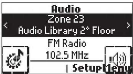
The control unit will now display the icons relating to the options most frequently used by the user:
- Touching Menu displays the control unit's main menu;
- Touching Setup displays the management menus of the audio zones;
- Touching 🖱️ displays another menu with which you can either switch off the zone or change the source of the audio signal to transmit in the audio zone
- Touching 🖱️ displays the control menu of the associated transmitter module.
System components
6.2 Audio input with 2 RCA connectors, automatic adjustment of the input sensitivity, integrated line terminator.
This device is used, via the 2 RCA connectors, to acquire, digitalize and transmit a generic analogical audio source (for instance a Hi-Fi system, CD player, portable MP3 player, etc.) over the By-me Bus.
The By-me Bus is galvanically decoupled from the audio inputs.
It is supplied in the following versions:
20582: 2 Eikon modules
19582: 2 Arké modules
14582: 2 Plana modules
Technical characteristics
- Rated supply voltage: BUS 29 V
- Protection class: IP30
- Galvanic decoupling of the audio inputs in relation to the By-me bus.
- Possibility of manual control of the input sensitivity.
- Operating temperature: -5 - +45 °C (for indoor use)
- Installation: flush or surface mounting (with surface mounting box 09975...)
- Consumption: 35 mA.
- Possibility of programming the relevant group via the control unit
- Push-button for configuration and manual setting of the input sensitivity.
- Two-colour LED for configuration and manual setting of the input sensitivity.
Indicators
- red LED: on steady during the configuration phase;
- green LED on steady: the device is lit;
- green LED blinking fast: control phase to increase the input sensitivity
- green LED blinking slow: control phase to decrease the input sensitivity
- orange LED (fixed or blinking): volume approaching the highest threshold
Operation
This device enables transmitting via bus the audio signal from an analogue sound source (all the audio sources marked with the "headphones" or "line out" symbol are suitable).
When the device is active the LED, if enabled via the control unit, is a steady green light; whereas the LED becomes orange if the level of the input signal is near the maximum threshold.
The optimal setting for the level is obtained when the LED is mainly lit green and the orange LED rarely comes on.
Note: An input signal volume that is too high can distort the audio signal.
System components
Settings which can be configured directly from the device
To adjust the sensitivity of the audio inputs on the device manually, proceed as follows:
- Activate the device (status LED on) by switching on a listening zone.
- Press and hold down the configuration button to increase the sensitivity.
The LED blinks quickly; if the maximum value is reached, or in any case on releasing the button, the LED will return to its normal operating status.
- Press and hold down the configuration button to decrease the sensitivity.
The LED blinks slowly; when the minimum value is reached, or in any case on releasing the button, the LED will return to its normal operating status.
- Whenever the configuration push-button is pressed, the sensitivity adjustment is inverted.
It is possible to run through the whole sensitivity adjustment scale, from the minimum to the maximum value and vice versa in approximately 60 sec.
As in normal operation, also while making the adjustment, the orange LED will light up to indicate that the intensity of the input audio is approaching the maximum threshold.
The optimum adjustment is reached when the orange LED is seen to light up with a certain frequency. A LED that is always green indicates too low an input signal; a LED that is always orange indicates too high an input signal.
Settings that can be configured via the control unit
• LED control: Normal/Off; default value Normal
If the device is active the green LED is lit.
• Mono/Stereo: default value Stereo.
Select the type of signal supplied on the RCA connectors; use the LEFT input for mono signals.
Device reset
On the control unit select Configuration → Reset management → Device reset and press the device configuration button; the red LED will light up. Hold down the button until the LED goes out (approximately 10 sec.).
Resetting:
- deletes the groups;
- resets the default parameters;
- deletes the physical address of the device.
System components
6.3 FM radio tuner with RDS, coaxial connector for external FM aerial, integrated line terminator, installation on DIN rail (60715 TH35), occupies 2 modules of 17.5 mm.
The FM tuner 01900 is able to send the digital audio signal and the RDS messages received by radio over the bus. The FM tuner receives the radio stations (with the related RDS information) in the 87.50 - 108.00 MHz band and in addition allows saving up to 8 different radio stations, to then be able to call them up with commands sent over the Bus by the By-me control devices or save in the scenarios.
N.B. If the radio function is included in the scenarios, together with the groups of the receivers also the radio module must be added so as to save the station to call up.
Technical characteristics
- Rated supply voltage: BUS 29 V
- Consumption: 35 mA
- Dissipated power: 1 W
- Installation: on DIN rail (60715 TH35), size 2 modules
- Operating temperature: -5 - +45 °C (for indoor use)
- Possibility of manual control of the input volume
- Push-button for configuration and manual setting of the input volume
- Two-colour LED for configuring and indicating ON/OFF status of operation
- F-type female connector for external antenna
- 2 jumpers to insert the line termination
- Jumper to select the type of antenna (1 = external antenna on connector F; 2 = use the Bus cable as an antenna)
Indicators
- red LED: on steady during the configuration phase;
- green LED on steady: the device is lit;
- green LED blinking fast: control phase to increase the input volume
- green LED blinking slow: control phase to decrease the input volume
- orange LED (fixed or blinking) : input signal approaching the highest threshold
Operation
The FM radio receiver with RDS 01900 is used as a digital audio signal transmitter within the speaker system. It therefore receives the FM radio signal of the station tuned to, digitalizes it and sends it to the various receiver devices of the system that requested it.
The main functions of the device are:
- Enabling or disabling the transmission of the audio content related to the FM radio (ON / OFF)
- Selecting a specific radio station
- Tuning onto the previous or next frequency in steps of 50 kHz
• Automatic frequency search with SNR above a given settable threshold
• Saving up to 8 different radio stations - Possibility of calling up a specific memory/station (also from a scenario)
- Scanning the memories in succession in both increasing and decreasing directions
- Scenario management, calling up a specific radio station on activating the scenario
- Compatibility with the call mechanism: the device frees the audio transmission channel if the call takes place on the same channel it uses (the "call" is a service provided by the microphone module).
- Sending information related to the tuned frequency
- Sending information related to the strength of the radio signal received (RSSI)
- Sending information related to the On/Off status
System components
- Sending information related to the value of the tuning memory (from 1 to 8).
- Sending, if available, RDS information received from the broadcasting radio station.
Settings which can be configured directly from the device
- To set the type of antenna, that is to say external on connector F or internal on the bus, you need to use the jumper situated next to the antenna connector, that is:
-
Antenna on connector F: Connect together pins 3 with 5 and 4 with 6
-
Antenna on bus: Connect together pins 3 with 1 and 4 with 2
To set the FM radio input volume manually, proceed as follows:
- Activate the device (status LED on) by switching on a listening zone.
- Press and hold the configuration push-button to increase the sensitivity.
The LED blinks rapidly; when the maximum value is reached or the push-button is released, the LED returns to its normal operating status.
- Press and hold the configuration push-button to decrease the sensitivity.
The LED blinks slowly; when the minimum value is reached or the push-button is released, the LED returns to its normal operating status.
- Whenever the configuration push-button is pressed, the sensitivity adjustment is inverted.
It is possible to run through the whole sensitivity adjustment scale, from the minimum to the maximum value and vice versa in approximately 90 sec.
Just as in normal operation, during adjustment the illumination of the orange LED indicates that the input audio intensity is approaching the maximum threshold.
The optimal setting is reached when the orange LED lights up rather frequently; the green LED on steady indicates too low an input signal while the orange LED on steady indicates too high an input signal.
Settings that can be configured via the control unit
- LED control: Normal/Off; default value Normal. If the device is active the green LED lights up to indicate information on the volume of the radio, otherwise it is off. If this parameter is set with the value 0, the green LED always remains off.
- Mono/Stereo: default value Stereo.
Selects the type of signal to transmit over the bus
• Percentage level of SNR: Default value 10%.
It is used during automatic frequency searching
- RDS On: default value On.
This value allows the device to send the RDS information over the bus (when available). If set to Off, the device sends no information.
- RSSI On: default value On.
This value allows the device to send the RSSI (received signal strength indication) information over the bus. If set to Off, the device sends no information.
Device reset
On the control unit select Configuration → Reset management → Device reset and press the device configuration button; the red LED will light up. Hold down the button until the LED goes out (approximately 10 sec.) Resetting:
- deletes the groups;
- resets the default parameters;
- deletes the physical address of the device;
- deletes the scenarios;
- deletes the saved stations.
System components
6.4 Home automation control module with four pushbuttons, RGB LED location in the dark with brightness control, to be completed with interchangeable half-buttons: 1 or 2 module Eikon, 2 module Arké or Plana.
01483: The device, connected to the speaker system bus, is equipped with a LINE OUT output used to take the non-amplified audio signal from the selected channel and send it, where required, to an amplifier. The device is also equipped with four independent push buttons that can also be configured as rocker switches, RGB LED with configurable colour, for setting and control functions in By-me home automation systems (control of lighting, roller shutters, audio functions, etc.).
01484: This device, equipped with 1 + 1 Wrms stereo amplifier, enables playing the audio data received on the Bus through the speakers connected to its outputs. The device is also equipped with four independent push buttons that can also be configured as rocker switches, RGB LED with configurable colour, for setting and control functions in By-me home automation systems (control of lighting, roller shutters, audio functions, etc.).
Common technical specifications
- Rated supply voltage: 29 V Bus
The device is also equipped with four independent pushbuttons that can also be configured as rocker switches, with RGB LEDs with configurable colour, for setting and control functions in By-me home automation systems (control of lighting, roller shutters, audio functions, etc.).
- Red LED and configuration button
- Jumpers to insert the audio line-end termination
- Operating temperature: -5 ÷ +45 °C (indoor use)
- Protection rating: IP20
- Installation: flush or surface mounting (with surface mounting box 09975..)
Characteristics art. 01483
- Terminals:
- 2 for the speaker system bus
- 2 for a By-me bus output for connecting up to 3 By-me devices
- 3 for connection to the external amplifier
- Absorption on the speaker system bus: 35 mA
- LINE OUT output for connection of external amplifiers
Characteristics art. 01484
- Auxiliary power supply (optional, used to avoid current consumption from the audio bus): 32 Vdc SELV
- Terminals:
- 2 for the speaker system bus
- 2 for a By-me bus output for connecting up to 3 By-me devices
- 2 for the auxiliary power supply at 32 Vdc. SELV
- 4 for the connection of the 2 audio speakers (8Ω, 1+1 W)
- Absorption on the speaker system bus:
- 150 mA max. if powered via BUS
- 10 mA if powered via 32 V auxiliary power supply
Depending on the dimensions of the audio system it is possible to install the auxiliary power supply 20580-19580-14580 so as not to have to use another power supply 01400 or 01401.
- 8Ω speaker output, 1+1 W rms
System components
Configuration
The pushbutton and rocker switch functional units have a group depth of 1 (that is, they can belong to one group only).
FUNCTIONAL UNITS
- For the pushbutton logic function you can select one of the following functional units:
- pushbutton
- dimmer control
- roller shutter control
- timer controlled command only*
timer controlled* and ON/OFF command - scenario control
- send value
- sleep (command for speaker system)
- audio monitoring (command for speaker system)
- For the pushbutton logic function you can select one of the following functional units:
- rocker switch
- dimmer control
- roller shutter control
- timer controlled command only*
- timer controlled* and ON/OFF command
- Volume On/Off ((volume control for speaker system)
- sleep (command for speaker system)
- ch+/track+ (command for speaker system)
- For the audio output only the audio output functional unit is available
* Configuration of the timer controlled command is only possible if there is at least one actuator in the group with the timer control function.
Selecting the functional unit to be configured:
After pressing the configuration button, before the red LED lights up (4 s), choose one of the following options:
- Short press the key you wish to configure as a pushbutton; the LED will light up white to confirm the selection made.
- Short press the key you wish to configure as a rocker switch; the white LED will light up to confirm the selection made.
- Pressing just the configuration button of the device alone automatically selects the roller shutter actuator function unit.
The LED/s of the pushbutton or rocker switch light up white to highlight the functional unit you are selecting.
After a pause of a few seconds the device enters configuration mode for the selected functional unit and the start of configuration is signalled by the red LED. At the end of this operation the red LED will go out.
System components
- Parameters of the audio zone to which the receiver belongs (audio output functional unit)
- priority
- sleep time (timer controlled switch-off)
- max volume of the zone
- max. switch-on volume
- call volume
- max. silencing volume
- behaviour of the zone switched off in the event of a general call
- behaviour of the zone switched off in the event of a selective call made to it
Scenarios
Each rocker switch can be dedicated to activation of one or two scenarios. The receiver can belong to up to 4 different scenarios and, for each scenario, save the status (volume and channel) to retrieve when activating the scenario
Device reset
On the control unit select Configuration→ Reset management → Device reset and press the device configuration button; the red LED will light up. Hold down the button until the LED goes out (approximately 10 sec.)
Resetting:
- deletes the groups;
- resets the default parameters;
- deletes the physical address of the device.
6.5 Stereo amplifier with 2 outputs for speakers 8 ohm 10 + 10 W, power supply 110-230 V 50-60 Hz, integrated line terminator, installation on DIN rail (60715 TH35), occupies 6 modules size 17.5 mm.
The stereo amplifier 01901 enables playing the audio signal received on the Bus through the speakers connected to its outputs.
Technical characteristics
- Rated supply voltage: 110-230V\~, 50-60Hz
- Terminals:
1) 2 for the speaker system bus
2) 2 for a bus output for connecting up to 3 By-me devices
3) 2 for the power supply at 110-230V\~
4) 4 for the connection to the 2 audio speakers
- Operating temperature: -5 - +45 °C (for indoor use)
System components
- Consumption on the bus: 20 mA
- Possibility of programming the receiver zone via the control unit
- Configuration button
- Installation: on DIN rail (60715 TH35), size 6 modules
- Red/green two-colour LED:
1) on red during configuration
2) blinking red following overheating of the amplifier
3) green to signal the state of the receiver, depending on the LED control parameter (which can be set at the time of configuration).
Configuration
During configuration, the audio receiver block saves the parameters and settings to work in its audio zone. This functional block can belong to only one group.
At the time of configuration, when the control unit asks you to press the device button, it is sufficient to press the device configuration button. The red LED emits a steady light that goes out at the end of configuration or after pressing the configuration button again.
Parameters
- LED control
- Power reduction
Besides these parameters there are the typical ones of the relevant zone:
- Priority;
- Sleep time (timed switch-off);
• Max volume of the zone
• Max. switch-on volume - Call volume
• Max. silencing volume - Behaviour of the zone switched off in the case of a general call
- Behaviour of the zone switched off in the case of a selective call
Scenarios
The receiver can belong to up to 4 different scenarios and, for each scenario, save the status (volume and channel) to retrieve when activating the scenario.
Device reset
On the control unit select Configuration → Reset management → Device reset and press the device configuration button; the red LED will light up. Hold down the button until the LED goes out (approximately 10 sec.)
Resetting:
- deletes the groups;
- resets the default parameters;
- deletes the physical address of the device.
System components
6.6 Docking station for iPod and iPhone devices, supplied with power supply - 2 modules. (The article is composed of 2 appliances of 2 modules each, can be installed also separately)
The docking station is a transmitter device that enables connecting audio sources such as iPod/iPhone (or other mp3 players, CD players, etc.) to the speaker system; the docking station acquires, digitalizes and sends over the By-me bus the signal of one of the analogue audio sources connected to it.
The device not only sends an audio signal to the receiver devices, but also remotely controls the iPod/iPhone (play/pause, skip+/- song, database navigation, playback property settings), by sending the appropriate commands over the bus.
The By-me bus is galvanically decoupled from the audio inputs (connector for iPod/iPhone or 3.5mm stereo jack).
It is supplied in the following versions:
20585: 2 Eikon modules
19585: 2 Arké modules
14585: 2 Plana modules
Technical characteristics
- Rated supply voltage: BUS 29 V
- Consumption: 35 mA
- Galvanic decoupling of the audio inputs in relation to the By-me bus.
- Protection class: IP30
- Possibility of manual control of the input sensitivity.
- Operating temperature: -5 - +45 °C (for indoor use)
- Installation: flush or surface mounting (with surface mounting box 09975...)
- 30-pin connector for Apple iPod/iPhone devices.
- Auxiliary 3.5 mm stereo jack for external audio sources (iPod/iPhone audio automatically excluded when the jack is in).
- Push-button for configuration and manual setting of the input sensitivity.
- Two-colour LED for configuration, manual setting of the input sensitivity and indication of the ON/OFF status of operation
Indicators
- red LED: on steady during the configuration phase;
- red LED flashing for about 60 s: indicates either no or incorrect voltage on the input terminal (5V -1A) for charging the iPod/iPhone;
- green LED on steady: the device is lit;
- green LED blinking fast: control phase to raise the device input sensitivity
- green LED blinking slow: control phase to lower the device input sensitivity
- orange LED (fixed or blinking) : input signal approaching the highest threshold
When the device is active the LED, if enabled via the control unit, is a steady green light whereas it becomes orange if the input audio signal approaches the value beyond which distortion is produced.
Operation
The docking station enables connecting an iPod/iPhone to the speaker system and controlling its main functions of navigation and playback; in addition, the device charges the batteries of the iPod/iPhone.
The remote controls are always available (both from the control unit and from the controls of the speaker system) and are the following:
- Play/Pause: starts/stops playback of the selected song.
- Skip Next/Previous: plays the next or previous song in the playlist.
If the device remote control mode is also enabled, via the control unit it is possible to navigate within the database of the connected iPod/iPhone and if necessary select the songs to play.
System components
The additional controls of the remote control mode are the following:
- Select the navigation category (choose from Playlists, Artists)
- Next/Previous Playlist: displaying the next or previous Playlist
- Next/Previous Artist: displaying the next or previous Artist
- Next/Previous Album: displaying the next or previous Album
- Next/Previous Song: displaying the next or previous Song
- Display information on the song currently being played: title of the song, name of the artist and title of the album.
- Select the song playback mode (Shuffle):
- Shuffle OFF
- Shuffle Songs
- Shuffle Albums
- Select the song playback mode (Repeat):
- Repeat OFF
- Repeat 1 Song
- Repeat all Songs
Warning: The changes to the Shuffle and Repeat settings that are made while the iPod/iPhone is connected to the docking station have effect only as long as the device remains connected and therefore do not change those previously set. These settings will be restored as soon as the Apple device is disconnected from the docking station.
IMPORTANT: The 30-pin connector can be used only for connecting and charging iPod/iPhone devices. The list of compatible Apple products is given on the label on the outside of the packing of the docking station 20585-19585-14585.
The 3.5mm auxiliary jack input enables connecting different sound sources to the iPod/iPhone (for example, MP3 players, CD players etc.); inserting such a jack automatically cuts off the audio coming from the iPod/iPhone.
Warning: It is not possible to control external players connected via the auxiliary jack and therefore not even receive information about them.
Settings which can be configured directly from the device
To manually adjust the sensitivity of the audio inputs on the device, proceed as follows:
- Activate the device (status LED on) by switching on a listening zone.
- Press and hold the configuration push-button to increase the sensitivity.
The LED blinks rapidly; when the maximum value is reached or the push-button is released, the LED returns to its normal operating status.
- Press and hold the configuration push-button to decrease the sensitivity.
The LED blinks slowly; when the minimum value is reached or the push-button is released, the LED returns to its normal operating status.
- Whenever the configuration push-button is pressed, the sensitivity adjustment is inverted.
It is possible to run through the whole sensitivity adjustment scale, from the minimum to the maximum value and vice versa in approximately 60 sec.
Just as in normal operation, during adjustment the illumination of the orange LED indicates that the input audio intensity is approaching the maximum threshold.
The optimal setting is reached when the green and orange LEDs alternate quite frequently; the green LED on steady indicates too low an input signal while the orange LED on steady indicates too high an input signal.
System components
Settings that can be configured via the control unit
• LED control: Normal/Off; default value Normal
If the device is active the green LED is lit, otherwise it is off; if this parameter is set with the value Off, the green LED always remains off.
- Mono/Stereo: default value Stereo.
Select how the input audio signal must be handled.
By setting Stereo, the right and left channels are treated as independent; with the Mono setting only the "left" channel audio line is used that is then duplicated on the "right" channel.
• Control: Remote/Local (default value Remote).
- Remote: it is possible (via the control unit or touchscreen) to control the connected Apple device completely, however this disables the interface for the local controls of the iPod/iPhone.
- Local: the local interface remains active for navigation on the iPod/iPhone, while remote control is reduced to only the Play / Pause and Skip Next / Previous controls
Device reset
On the control unit select Configuration → Reset management → Device reset and press the device configuration button; the red LED will light up. Hold down the button until the LED goes out (approximately 10 sec.)
Resetting:
- deletes the groups;
- resets the default parameters;
- deletes the physical address of the device.
6.7 Bluetooth® technology interface for home automation.
The device is a Bluetooth technology interface that acts as a transmitter in the speaker system to input the audio from a smartphone or tablet (Android, iOS and Windows Phone) on a BUS channel. In addition to transmitting the audio signal to the receiver devices, it is also used to control the smartphone or tablet remotely by sending commands over the bus.
The device not only sends an audio signal to the receiver devices, but also remotely controls the iPod/iPhone (play/pause, skip+/- song), by sending the appropriate commands over the bus.
It is supplied in the following versions:
20589: 2 Eikon modules
19589: 2 Arké modules
14589: 2 Plana modules
Technical characteristics
- Rated supply voltage: 29 V Bus
- Power consumption: 35 mA
- Terminals:
- 2 for the speaker system bus
- 2 for a By-me bus output for connection of up to 3 By-me devices
- RGB LED indicating the status of the internal radio module and the device configuration phase
- Configuration pushbutton
- Jumpers to insert the audio line-end termination
- Operating temperature: -5 ÷ +45 °C (indoor use)
- Protection rating: IP20
- Installation: flush or surface mounting (with surface mounting box 09975..)
System components
- Supports Bluetooth® technology version 4.2 and is compatible with Bluetooth® profiles A2DP 1.3 and AVRCP 1.6.
Operation
- Possibility to store up to 8 mobile devices (smartphone, tablet, etc.).
N.B.: Any ninth device stored overwrites the first one stored, and so on. - Pairing: the internal radio module searches for a mobile device to store.
- The Bluetooth technology interface allows you to play the audio content on mobile devices over the speaker system and to control the following functions:
- Play/Pause: starts/stops playback of the selected song.
- Track+/-: used to scroll through a playlist, moving to the next or previous track.
• Used to send information about the track, album and artist being played to the bus. - The volume can be controlled directly from the smartphone or tablet.
Configuration button
- If the configurator is waiting to configure a device, a short press will put the device in configuration.
- If the configurator is waiting to delete a device, a long press (10 s) will reset the device.
- In normal operation, press the internal radio module briefly to switch it on or off.
-.In normal operation, a long press (10 s) activates the Pairing function. If no remote device is found, this procedure is terminated after a timeout of 90 s.
Indicators
- LED steadily lit with the colour set in configuration: internal radio module on but interface off.
- LED flashing with the colour set in configuration: interface on and transmitting an audio signal over the bus.
- LED flashing red: input signal exceeds preset limit (lower the volume on the smartphone/tablet).
• LED flashing blue: Pairing function activated.
Settings that can be configured from the control unit
- LED ON brightness: allows you to select the brightness level of the LED when the module or device are on (high brightness, medium brightness, low brightness. off)
- LED OFF brightness: allows you to select the brightness level of the LED when the module or device are off (high brightness, medium brightness, low brightness. off)
- LED colour: allows you to select the colour of each individual LED from a predefined list or to set the desired RGB coordinate directly.
- Mono/Stereo: default value Stereo.
- Signal gain: allows you to set, in the range 0 to 100, the gain relative to the audio signal received via Bluetooth technology and sent over the bus.
Device reset
On the control unit select Configuration Reset management Device reset and press the device configuration button; the red LED will light up. Press and hold the button until the LED goes out (approximately 10 s).
Resetting:
- deletes the groups;
- resets the default parameters;
- deletes the physical address of the device;
- deletes mobile devices saved on the radio module.
System components
6.8 Microphone for selective or general call, voice activation function to control the children (Baby Control) and for audio monitoring - 2 modules
The microphone 20586-19586-14586 is a transmitter device capable of picking up the signal detected by the built-in audio source and transmitting it, via a call procedure, to specific zones in the system (selective calls) or to all the zones (general call). The zones involved in the call switch over the receivers onto the carrier channel signalled by the call, they play back the audio content picked up by the microphone and finally, after the end of call message, they recommence the operation immediately prior to the call.
It is supplied in the following versions:
20586: 2 Eikon modules
19586: 2 Arké modules
14586: 2 Plana modules
Technical characteristics
- Rated supply voltage: BUS 29 V
- Terminals:
1) 2 for the speaker system bus
2) 2 for a By-Me bus output for connecting up to 3 By-Me devices
- Operating temperature: -5 to +45 °C (for indoor use)
- Installation: flush or surface mounting (with surface mounting box 09975..)
- Consumption: 35 mA
- Configuration button
- Central red configuration LED
- Maximum number of microphones that can be installed in the system: 8
- Front right-hand rocker switch that can be configured with the following functions:
- If configured in an audio output group:
1) On/Off audio zone plus volume adjustment
2) Changing track and audio source
3) Sleep (timed switch-off of an audio zone)
- If configured in a Call group
1) Audio Monitoring command, if configured with a remote call module
2) General and Selective Call Command if configured with the local call module (primary function of the button associated with the interchangeable buttons provided in the package).
- If configured in an automation group:
1) ON/OFF switch
2) Dimmer control
3) Roller shutters control
4) Scenario control
- Front lower left-hand push-button associated with the module's Baby Control function
- Two green LEDs located in the middle of the 2 rocker switches with functions that can be configured via the control unit
- Jumpers to insert the audio line termination
System components
Configuration
- Functional Units: 2 (right-hand rocker switch and microphone transmitter).
The functional unit related to the button, when not associated with the transmitter on which it resides, can belong to at most 4 groups; the microphone transmitter functional unit can belong to one group only.
- Selection of the functional unit in the configuration phase:
a. Press the central button:
b. Within 3 s press the right rocker switch to select the "right rocker switch" functional unit or the lower left-hand button to select the "microphone transmitter" functional unit; the red LED lights up.
c. With the red LED on, the control unit will configure the functional unit; at the end of this operation the LED will go out.
Operation
In the standard configuration of the front buttons, the following functions can be used:
- "Push To Talk" general call.
Instantaneous call on pressing the top right-hand front button and directed to all the system's zones; they will transmit the voice signal picked up by the device's microphone as long as the button is kept pressed.
The call ends when the button is released.
By using the control unit or EasyTool Professional, it will be possible to set the behaviour of every zone following a General call (for example the behaviour of the zone if switched off, the call playback volume, etc.).
- "Push To Talk" selective call.
Instantaneous call on pressing the bottom right-hand front button and directed to a subset of system zones; by using the control unit or EasyTool Professional, it is possible to set the zones receiving the selective call by accessing the device parameters (on the control unit the parameter is "Call Zone").
Only the audio zones corresponding to the selected ones, indicated in the selective call start message, will switch onto the call channel and will transmit the user message as long as the button is kept pressed.
The call ends when the button is released.
By using the control unit or EasyTool Professional, it will be possible to set the behaviour of every zone following a Selective call (for example the behaviour of the zone if switched off, the call playback volume, etc.).
• "Baby Control" service.
To turn this function on/off simply press and then release the bottom front left-hand button that will be followed by the LED signal.
Once the function has been activated, if the volume of the voice signal picked up by the microphone exceeds the set threshold, a selective call is sent to a set of system zones; the threshold value can be set with the control unit ("Baby Control Threshold" parameter) or with EasyTool Professional.
The call remains active until a few seconds after the audio has returned under the threshold value to then reactivate automatically when later on the threshold gets exceeded.
By using the control unit ("Baby Control Zones" parameter) or EasyTool Professional, it is possible to set the zones intended for the Baby Control service
The typical application of this function is monitoring children during their rest.
System components
• Audio Monitoring.
This function enables remote activation of the call microphone with a By-me automation button provided that both devices are configured in the same group.
It is then possible to monitor the audio of a specific room; this audio monitoring function is accomplished with the By-me button that activates a selective call, initiated by the microphone module, for a set of system zones. By using the control unit ("Audio Monitoring Zones" parameter) or EasyTool Professional, it is possible to set the zones for Audio Monitoring.
IMPORTANT:
- As an alternative to the standard configuration, that is forgoing "Push To Talk Calls" and maintaining the "Baby Control" and "Audio Monitoring" function, the two right-hand buttons of the microphone 20586-19586-14586 can be used as By-Me automation commands (lights, roller shutters, audio).
To do this, simply configure the right-hand rocker switch of the microphone in a lights or audio group.
- If there are a number of microphones 20586-19586-14586 in an installation, only one active Call is permissible (general or selective) in the system irrespective of audio channel availability.
- During call playback, the central LED of the rocker switches of the microphones 20586-19586-14586 signal there is a call by blinking (obviously this happens if the rocker switch is configured for the call functions).
Device reset
On the control unit select Configuration → Reset management → Device reset and press the device configuration button; the red LED will light up. Hold down the button until the LED goes out (approximately 10 sec.)
Resetting:
- deletes the groups;
- resets the default parameters;
- deletes the physical address of the device.
System components
6.9 Interface for transmitting By-me commands to IR receiver, together with 3 m cable.
The IR interface enables controlling audio sources (stereo combo, CD/DVD players, etc) learning and emulating the commands of the original remote control of the equipment to control. Associated with an RCA transmitter (art. 20582-19582-14582) it then allows having sound sources controlled directly by the By-me system.
It is supplied in the following versions:
20584: 2 Eikon modules
19584: 2 Arké modules
14584: 2 Plana modules
Technical characteristics
- Rated supply voltage: BUS 29 V
- Terminals: 2 for the By-me bus
- 2.5mm jack connector
- Operating temperature: -5 - +45 °C (for indoor use)
- Installation: recess-mounting 1 module
- Consumption: 20 mA
- Configuration button
- 3 m cable with 2.5mm jack and IR transmitter (supplied)
- Possibility of programming the group via the control unit (it must be associated with an RCA input module)
- Possibility of recording and repeating max. 12 buttons of an infrared remote control
- Two-colour LED for configuring and indicating infrared transmission and reception
Indicators
- red LED: on steady during the configuration phase;
- green LED on steady: the device is lit;
- blinking green LED: reception of a By-me command that requires sending IR commands
- blinking red LED: error in managing/recording an IR control
- blinking orange LED: reception of the By-me command for starting the learning phase and waiting for the configuration button to be pressed
- orange LED on steady: starting recording phase and waiting for an IR remote control button to send an infrared code
Operation
The device is able to save the button of an infrared remote control and repeat its operation after a By-me command. When the interface is active the LED, if enabled on the control unit, is lit steady on green; it flashes briefly each time a By-me command is received that involves sending IR commands.
It is possible to acquire up to 12 actions (action = repetition of an infrared remote control button) that, in the control unit menu, are named as follows:
| Action 1 |
| Action 2 |
| Action 3 |
| Action 4 |
| Action 5 |
| Action 6 |
| Action 7 |
| Action 8 |
| Action 9 |
| Action 10 |
| Action 11 |
| Action 12 |
System components
Operation is ensured when, starting with the actions, the following commands thus named on the control unit are coded:
Command Meaning
| On | Powering up the device, selecting the source and starting playing |
| Off | The device goes onto stand-by |
| Skip next | Next track/memory |
| Skip previous | Select previous track/memory |
| Play | Start playing |
| Stop | Stop playing |
| Pause | Pause playing |
| Resume | Exit pause and start playing again |
| Sel. Source 1 | Select source 1 |
| Sel. Source 2 | Select source 2 |
| Sel. Source 3 | Select source 3 |
Each command can be coded as the sequence of 1, 2, 3 or 4 actions and this corresponds to consecutively pressing up to 4 buttons on the remote control of the controlled device.
Configuration
The IR interface 20584-19584-14584 is configured by the control unit in two phases:
- Record button of a remote control (action)
- Associate actions with the actual command.
Creation of an action and recording the key of a remote control
Setup → Configuration → Groups → Audio groups → Select the group where the IR interface was added → Associated devices → Select the IR interface → Device parameters → A Acquired actions → Add
Set the index of the action and select Next → Acquire action
Press the configuration button of the interface 20584-19584-14584; the orange LED will be lit steady.
Move the remote control near to the IR interface (to a distance of about 10 cm) and continuously press the button you want to record.
Select lastly Save.
If acquisition is successful, the interface LED will flash green; the action will then be displayed on the control unit in the list of configured actions (A1, A2, etc.).
If the acquisition is not successful carry out the following check:
- position the remote control towards the window of the IR interface at a distance of about 10 cm;
- if the orange LED does not become red or green (flashing) check the operation of the remote control button on the audio device;
System components
- check that the infrared frequency of the audio device is between 30kHz and 60kHz;
- if the LED is blinking red try the entire sequence again.
As regards the remote control, you should save the buttons that are generally used for the ON, OFF, SKIP, PLAY, STOP, PAUSE and source selection (in the case of a multi-source device) operations and in the table below note down the reference between the name of the memory used and the corresponding remote control button.
| Action Remote control button |
| Action 1 |
| Action 2 |
| Action 3 |
| Action 4 |
| Action 5 |
| Action 6 |
| Action 7 |
| Action 8 |
| Action 9 |
| Action 10 |
| Action 11 |
| Action 12 |
The following page gives an example of configuring the remote control buttons and filling in the above table.
Modifying an action
Setup → Configuration → Groups → Audio groups → Select the group where the IR interface was added → Associated devices → Select the IR interface → Device parameters → Acquired actions → Select the action to modify
The available options are the following:
- Acquire action
- Press the interface configuration button and then the remote control button to be associated.
- Remove action
- Proceed to remove the action? → Yes.
The selected action is deleted and the control unit confirms the operation has concluded.
System components
Associate actions with the actual command.
This menu is used to create the commands associating up to 4 already recorded actions.
Setup → Configuration → Groups → Audio groups → Select the group where the IR interface was added → Associated devices → Select the IR interface → Device parameters → Associate commands
Select the command to associate (switching on, off, etc.); 4 selection fields (Action 1, Action 2, Action 3 and Action 4) are then displayed, each one of which represents an action associated with the command.
The 4 fields will show dashes if there is no associated action.
It is now possible in each field to choose any of the recorded actions; the fields are indexed from 1 to 4 that is the order in which the actions will be performed by the command.
Lastly touch Set that causes the data to be transferred to the IR device.
Other parameters
On the screen for the parameters of the IR interface there are also:
- LED management: (default 1= enabled). If the device is active the green LED is lit.
- Half time [sec]: (default value 1 s). Time in seconds that must pass between one repetition of an IR button and another one, that is between consecutive actions mapped within the same command. If the consecutive actions refer to the same button, the inter-time is not applied.
Example.
| Action Remote control button |
| Action 1 POWER |
| Action 2 SKIP+ |
| Action 3 SKIP- |
| Action 4 PLAY |
| Action 5 STOP |
| Action 6 PAUSE |
| Action 7 CD |
| Action 8 RADIO |
| Action 9 AUX |
| Action 10 - |
| Action 11 - |
| Action 12 - |
System components
| Command Action 1 Action 2 Action 3 Action 4 |
| On Action 1 Action 7 Action 4 None |
| Off Action 5 Action 1 None None |
| Skip next Action 2 None None None |
| Skip previous Action 3 None None None |
| Play Action 4 None None None |
| Stop Action 5 None None None |
| Pause Action 6 None None None |
| Resume Action 4 None None None |
| Sel. Source 1 Action 7 None None None |
| Sel. Source 2 Action 8 None None None |
| Sel. Source 3 Action 9 None None None |
In the example above note that the On command is coded as the playback sequence of Actions 1, 7 and 4 that correspond to pressing the POWER, CD and PLAY buttons of the original remote control in sequence. The operation of switching on is then associated with the actions of the three buttons indicated alternated by the inter-time parameter that causes switching on the device, selecting the CD source and starting playback as required for the Power On command.
Device reset
On the control unit select Configuration → Reset management → Device reset and press the device configuration button; the red LED will light up. Hold down the button until the LED goes out (approximately 10 sec.) Resetting:
- deletes the groups;
- resets the default parameters;
- deletes the physical address of the device.
The Reset operation does not delete the memory of the infrared remote control buttons or the coding of any commands.
Summary of signals of IR interface 20584-19584-14584
| Problem | Cause | Solution |
| During the phase of adding a device the control unit display shows "Not a valid device". | There is no association with an RCA 2-input device. | First add an RCA 2-input device and then the IR interface to the group. |
| The green status LED does not come on or does not flash. | Check that the LED parameter is enabled. | |
| The green status LED does not come on or does not flash yet. | Before being able to receive other types of commands, the IR interface must be on | Send the on command (if enabled, the green LED must be on steady to receive other commands) |
System components
| Problem Cause Solution | ||
| The audio system is not controlled. | Check that, on sending the By-me command, the green LED blinks.Check the IR cable; it must be positioned about 1 cm from the receiver. If necessary, before positioning the transmitter with the adhesive, test the send sequence varying the position.Check you have recorded the button for the desired command with the corresponding By-me command. | |
| A command does not produce the desired function. | While having been correctly coded, it might not be sufficient to send the command by pressing the associated IR button just once. | Map the repetition of the same Button on the same Command in consecutive positions.For example, the Play command could be coded as Action 1 = Button 4, Action 2 = Button 4, Action 3 = None, Action 4 = None (this is presuming you have saved the Play button of the remote control on Button 4). This action causes repeated pressing of the play button associated with the Play command. |
6.10 Decoupler for Bus line / speaker system for By-me power supply, integrated line terminator, installation on DIN rail (60715 TH35), occupies 2 modules of 17.5 mm.
The line decoupler 01902 is the device that divides the By-me system into:
- automation part (free wiring, BUS cable art. 01840.E);
- speaker system part (in-out linear wiring, BUS cable art. 01840.E.B).
The speaker system is therefore delimited by this device that depending on the case can be directly connected at the output to the power supply 01401 or to the line coupler 01845.1 or directly to the Bus of the automation part.
Technical characteristics
- Rated supply voltage: BUS 29 V
- Operating temperature: -5 - +45 °C (for indoor use)
- Installation: on DIN rail (60715 TH35), size 2 modules
6.11 Tap-off for By-me command devices, flush mounting (retrofit).
The shunt 01903 is used for shunting from the speaker system line (in-out linear wiring, Bus cable art.01840.E.B) to make an automation branch (free wiring, Bus cable art.01840.E) to which can be connected up to 10 By-me devices.
6.12 Branch tap-off for speaker system devices, flush mounting (retrofit)
The shunt 01904 is used for shunting two new audio branches from a speaker system line thus making it possible to create a star. This solution is useful in all those cases where the linear wiring is difficult or not feasible.
Group/zone definition
7. Group/zone definition
To configure the system it is necessary, first of all, to create the groups/zones for the speaker system; the procedure to follow is similar to the one for creating home automation system groups (Automations, Load Control, HVAC control, etc.).
7.1 Managing audio groups
7.1.1 Creating a group
When creating groups it is necessary to follow some rules concerning the logical subdivision of the parts comprising the audio system.
The maximum number of groups relating to the transmitter modules is equal to 4 except for the microphone call module whose maximum number is 8.
First create the groups where there are transmitters adding, for each group, a single transmitter (for example Audio source 1, etc.); it is advised to choose names containing the name of the room.
Setup → Configuration → Groups → Audio groups
It is a good rule to configure the transmitter devices first; then create the groups related to the receiver modules and the control buttons (including those connected to the automation line).
7.1.2 Removing a group
Setup → Configuration → Groups → Audio groups → Select the group by scrolling through the list → Remove group → Delete all information associated with the selected group? → Yes
It is not possible to remove a group as long as it is associated with an Audio zone.
7.2 Managing audio zones
7.2.1 Creating an audio zone
Main menu→Audio → Setup → Zone management → Add
Set the index and the name of the zone and select the relevant audio group for the desired zone; confirm by touching Save.
The control unit confirms the operation and returns the screen to the list of registered zones.
7.2.2 Removing an audio zone
Main menu → Audio → Setup → Zone management → Select the zone to remove → Remove zone → Proceed to remove the zone? → Yes
The control unit confirms the operation and returns the screen to the list of registered zones.
7.3 Audio zone settings
For each configured audio zone, this enables setting the parameters associated with it (not frequent).
Main menu→Audio→Setup→Zone setting→Select the desired zone
Then proceed to set the parameters by touching (the ones listed below:
Group/zone definition
■ Priority
An audio channel can be transmitted from one or more zones simultaneously by tuning onto a specific transmitter module.
The control buttons for the various zones can perform actions involving the transmitter module (change radio station, play/stop a song); therefore the command generated by one zone could also affect the sound in another.
This parameter determines the right to execute these commands, that will be performed if one zone has a priority greater than or equal to another.
5= maximum priority
0= minimum priority
Select the desired value and confirm with Set.
■ Audio sources
One zone transmits the audio source selected by the user in the specific menu.
This parameter enables selecting which audio sources must be considered as active for this zone.
Scroll through the list of sources, select the one you want and confirm with Set.
This parameter sets the time in minutes after which the zone is switched off; the time is counted by the receivers from the moment the dedicated command is received.
0= minimum value
300= maximum value
Select the desired value and confirm with Set.
■ Max volume [%]
This parameter sets the maximum value of the volume used by the receivers in this zone as a percentage.
0= minimum value
100= maximum value
Select the desired value and confirm with Set.
Note: For uniformity it is advised to create audio zones with receivers that all have the same sound power.
■ Max switch-on volume [%]
This parameter sets the maximum value of the volume used by the receivers in this zone at the time of switching on as a percentage.
0= minimum value
100= maximum value
Select the desired value and confirm with Set.
Note: For uniformity it is advised to create audio zones with receivers that all have the same sound power.
■ Call volume [%]
This parameter sets the value used by the receivers in this zone at the time of the voice microphone call on as a percentage.
0= minimum value
100= maximum value
Select the desired value and confirm with Set.
Group/zone definition
■ Max silencing volume [%]
This parameter sets as a percentage the maximum value used by the receivers in this zone at the time of the request for operation in Silencing mode.
0= minimum value
100= maximum value
Select the desired value and confirm with Set.
■ General switch-on
This parameter determines if, when off, the zone must switch on when a general call arrives.
On= on, Off=off
Select the desired operation and confirm with Set.
■ Selective switch-on
This parameter determines if, when off, the zone must switch on when a selective call arrives.
On= on, Off=off
Select the desired operation and confirm with Set.
7.4 Alarm clock function
It is possible to create the alarm clock function by taking advantage of the capacity offered by the By-me control unit. It is basically a matter of activating one of the audio zones at a certain time, with a state of operation defined by the user; it is possible to associate these two characteristics respectively with an "event" and with a "scenario". For example, suppose you want to use an audio zone for waking up in the morning.
The first operation to carry out is to create a scenario that includes the audio groups related to the desired zone including the group of the transmitter:
Scenarios → Setup → Add → Create the scenario
To create a more complete setting, the scenario can also include the Automation groups (for more information please see the relevant section in the manual on Scenarios).
The second operation to carry out is to create an event
Events Programmer → Setup → Add → Create the event
After setting the name, enable the timed function of the event setting the Periodical Clock mode; it is possible to configure up to two On and Off events for each day of the week.
Afterwards, set the relevant parameter for the OUT outputs with the SCN Scenario type and select the audio scenario previously created (for more information see the section of the manual on Events).
7.5 Viewing the audio zones
After creating the groups and then the audio zones, the main menu shows the zones created, that can be scrolled through by moving to the left (<) or to the right (>).

Group/zone definition
For each zone the display shows the number and the description, the description of the group of the transmitter module associated with the channel (audio source), the description of the transmitter module and, where applicable, some supplementary information (in this case the frequency for the FM tuner).
With the 📄 icon a submenu is displayed in which touching
- Switch off zone (dynamics depending on the status) switches off the zone;
- Change sound source selects the sound source to play.
When the same icon corresponds to the speaker symbol with ON written above, it means that the zone is off; On touching it, it will switch on.

7.5.1 FM tuner control
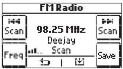
The above figure shows the control screen for the FM tuner transmitter module.
In the middle zone there is the frequency being used, the related signal strength (RSSI) and, only if enabled, the RDS text is displayed.
The word Scan indicates how it activates one of the three selectable setting modes, namely Mem, Scan and Freq.
The Scan and Scan icons perform the action of increasing and decreasing according to the selected mode.
In Mem mode the frequency being used corresponds to the value of one of the station memories.
■ Saving the radio stations
In the Scan or Freq mode it is possible, by touching the frequency in one of the 8 available station memories.


icon, to save the current

Set the desired station number, select Next and confirm with Yes.
Group/zone definition
■ Selecting stations in memory
Touching Mem activates the mode for calling up previously saved stations; with icons and you can call up one of the 8 saved FM stations.

The number alongside Mem is the selected station number.
■ Automatic search for radio stations
Touching Scan activates the automatic radio station search mode; with icons Scan and Scan you move in one of the two directions.
The parameters affecting the search can be changed via the menu for the device parameters.
■ Frequency selection
Touching Freq activates the mode for setting the current frequency; with icons [Freq] and [Freq] you move in one of the two directions. Keep the icons pressed for scrolling faster.
7.5.2 Bluetooth technology interface control
The Bluetooth technology interface control menu consists of a single screen on which the central part is used to display complete information about the tracks being played.

The buttons used to manage the Bluetooth technology interface are the following:
• and to play the previous or next track
- to pause playback of the track and restart it at the point where it was stopped
Group/zone definition
7.6 Managing the Docking Station
The Docking Station is controlled with two menus:
- the song playback menu (Playback) that is accessed from the Zone Menu;
- the database navigation menu in the Docking Station that is accessed from the Playback Menu.
If no iPod/iPhone is connected to the Docking Station or a jack connector is connected to the socket of the auxiliary source, the Zone Menu will show the notice Dockingstation? and it will not be possible to use the Playback Menu or play back songs (the button at bottom left is inhibited).
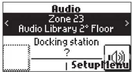
If an iPod/iPhone is connected, the Docking Station sends a message to the control unit and it is then possible to open the Playback Menu by touching the Details icon (the button at bottom left that is now enabled).
7.6.1 Playback Menu
The Playback menu of the Docking Station is composed of a main screen on which the middle part is used for a full display of the relevant information on the tracks being played.

Group/zone definition
The buttons used to manage the iPod/iPhone are the following:
• and to play the previous or next track.
• to access the Navigation Menu of the Docking Station.
• ■ to pause track playback and restart it at the point where it was stopped.
• | b | to return to the Zone Menu.
• to set repetition of a single track or of a group of tracks.
• to set random playback of a group of tracks.
Touching 📊 the two icons 🎋 and ✕ opens a new page for selecting playback mode; the 4 options shown below are displayed and by touching 📊 each one you can enable/disable the related playback mode.
The icons corresponding to the selection made will then be on the Playback menu selection button.
no repetition random group of tracks
single track ordered playback
group of tracks random group of albums
If the Docking Station is controlled Locally (that is to say directly from the iPod/iPhone) the Playback Menu will not display the song being played and the tracks will be managed with the three command and playback icons.

7.6.1.1 Operation
The main screen of the Playback Menu shows the relevant information on the Artist, Album, and Song being played.
This information will always be displayed when the iPod/iPhone is on Play or Pause while if it is on Stop the displayed fields will be empty.
In the case of Stop and Pause the [icon] and [icon] icons will not be displayed.
Pressing each of the icons , and of the main screen changes song playback as preferred.
Group/zone definition
The information on the song being played is continually updated: when the iPod/iPhone starts playing a track the control unit immediately displays the relevant information.
Song playback can also be changed by the events generated by By-me rocker switches configured in audio Groups or by the rocker switches of the receivers.
Touching within 3 s of the start of the song will play the previous song.
Touching □ after 3 s of the start of the song will play the current song from the start
Touching ▶ plays the next track.
7.6.2 Docking Station Database Navigation Menu
From the Playback menu, touching 📋 accesses the Navigation menu.
The Docking Station database navigation menu is composed of a main screen on which the middle part is used for a full display of the navigation information.
The icons and procedures with which the Database is navigated are the following:


- Move to the left < and to the right > to display the categories or elements.
• and to select a category or one of its specific elements.
• to return to the Playback Menu.
• to play the selected category.
Touching 📋 or ➤ when a specific category has been selected takes you back to the Playback menu.
The docking station navigation menu is composed of different screens depending on the categories and the selected elements; as a result the icons that can be displayed are the following:
• to return to the selection menu of the Artists/Playlists category.
• to select an artist and display his or her albums.
• to return to the selection menu of the Artists category.
• to select the album and display the songs it contains.
Group/zone definition
- return to the list of artists.
- return to the list of albums.
- to return to the Playlist.
• to return to the previous menu.
7.6.2.1 Operation
The database of the iPod/iPhone can be browsed by Playlist or Artist and navigation is permissible also while playing a song.
During navigation, the type of category currently selected is highlighted by the relevant identifying image. After selecting the desired type of category, it is possible to send it to playback with the ▶ icon thus returning automatically to the Playback screen.
Pressing | b | you go back to the Playback menu.
7.7 Details menu of the RCA source associated with the IR interface 20586-19586-14586
From the zone menu, it is possible to access the menu of commands associated with the IR interface.
Each command can be coded as a sequence of 1, 2, 3 or 4 actions and this corresponds to consecutively pressing up to 4 buttons on the remote control of the controlled device.
More precisely, the association of the commands with the 4 menu buttons is the following:

Important:
All the commands are cyclic; for example:
- Touching 1 time activates the Pause control; touching it again activates Resume; touching the icon yet again activates Pause and so on.
- Touching the button 1 time activates Sel. Source 1; touching the icon again activates Sel. Source 2; touching the icon yet again activates Sel. Source 3; touching the icon again activates Sel. Source 1 and so on.
Group/zone definition
7.8 Adding devices to a group
Used to add new devices to an existing group.
For all the details see the section of the manual on the methods of creating groups.
Setup → Configuration → Groups → Audio groups → Select the desired group → Associated devices → Add
During group creation it is necessary to keep the following rules in mind:
- Create the groups related to the transmitter modules first.
- It is not possible to add any other devices to a group that contains the FM Tuner module or the Docking Station.
- In a group that contains the RCA input it is possible to add only 1 call microphone 20586-19586-14586.
- Only the functional blocks related to the push-button or rocker switch controls can be added to a group that contains the call module.
- Only the functional blocks related to the rocker switch controls can be added to a group that contains one or more receiver modules.
- It is not possible to add any rocker switch controls and/or push-buttons to a group without any transmitter or receiver modules.
- A receiver can only be configured in an audio group.
- A rocker switch that has been configured in an audio group or in a call group cannot be configured also in an automation group and vice versa.
NOTE: Since the quantity of data exchanged is very high, the device configuration procedure can even take a few dozen seconds.
7.9 Removing devices from a group
Used to remove functional blocks from a group
Setup → Configuration → Groups → Audio groups → Select the group scrolling through the list → Associated devices → Select the functional unit to remove → Remove device → Proceed to remove the device → Yes
7.10 Modifying device parameters
Device parameters can be modified in order to personalize and adapt the characteristics of the system to different installation requirements.
Setup → Configuration → Groups → Audio groups → Select the group scrolling through the list → Associated devices → Select the functional unit scrolling through the list → Device parameters
The modifiable parameters for each functional unit depend on the characteristics of the unit and vary by type depending on the device considered (see the instructions sheets provided with each article).
7.10.1 Device parameters
■ Functional unit – Audio output /DIN
• LED management: Off, Normal, Reverse, Always On
• Output power reduction = Off, On
This parameter must be set On when the 3M, 3W 8Ω flush-mounting passive acoustic speaker is connected (art. 20587)
Group/zone definition
■ Functional unit – RCA Audio Input
• LED management: Off, Normal
• Audio type: Mono, Stereo
■ Functional unit - FM tuner
• LED management: Off, Normal
• Audio type: Mono, Stereo
• Search threshold: 0%, 100%
This is the threshold beyond which a station is considered as valid during an automatic search
- RDS text: Off, On
- RSSI : Off, On
■ Functional unit – Microphone/Call
• LED management: Off, Normal
- Baby Control threshold = from 0 to 15 (0 = maximum activation sensitivity)
This is the threshold of the audio signal captured by the microphone, beyond which the "Baby Control" function is activated
- Call zone: On, Off, zone by zone
This is used to select the audio zones to activate during a "Push to Talk" selective call
• Baby Control zones: On, Off, zone by zone
This is used to select the audio zones to activate during a selective call corresponding to the "Baby Control" service
• Audio Monitoring zones: On, Off, zone by zone
This is used to select the audio zones to activate during a selective call corresponding to the "Audio Monitoring" service
■ Functional unit – Rocker switch for Audio control
- LED management: Off, Normal, Reverse, Always On, Ctrl LED Normal, Ctrl LED.Reverse, Ctrl LED.On
• Operation: Default = On-Off/Volume
This functional block refers to a rocker switch control, configured automatically by the By-me control unit to perform the functions of zone switching on/off and adjusting the volume.
The Operation parameter can be changed later on according to the type of control: On-Off/Volume, Skip Channel/Track, Sleep Audio.
The LED control parameter can also have values for the double button with the central LED (except for the rocker switch of the call microphone 20586-19586-14586).
Note: When "Skip Channel/Track" operation is selected LED control is automatically disinhibited: the value of the "LED control" parameter becomes "Off".
| Skip Channel/Track operation | Rocker switch DX audio/By-me automation | Rocker switch CX By-me automation | Rocker switch SX audio/By-me automation |
| Parameter LED control | OFF Always ON | OFF Always ON CTRL Always ON | OFF Always ON CTRL Always ON |
Group/zone definition
■ Functional unit – Rocker switch for Audio Monitoring
- LED management: Off, Normal, Reverse, Always On, Ctrl LED Normal, Ctrl LED.Reverse, Ctrl LED.On
• Operation: Default = On Off
This functional block refers to a rocker switch control configured automatically by the control unit to perform the function of switching audio monitoring on/off; the Operation parameter must always remain set to Audio Monitoring.
The LED control parameter can also have values for the double button with the central LED (except for the rocker switch of the call microphone 20586-19586-14586).
■ Functional unit - IR stereo control
- LED management
■ Functional unit – Dock. iPod/iPhone Station
• LED management: Off, Normal
• Audio type: Mono, Stereo
• Control: Remote, Local
This enables controlling the iPod/iPhone from a remote position (that is from the By-me control unit and with the touch screens) or directly with the iPod/iPhone.
■ Functional unit - Bluetooth module
- RGB LED colour: red, green, blue, amber, white, cyan, magenta, custom
• LED ON brightness: OFF, Low, Medium, High
• LED OFF brightness: OFF, Low, Medium, High
• Audio type: Mono, Stereo
• Signal gain: 0%, 100% default=65%
Types of system
8. Types of system
This chapter, by way of example, illustrates some types of installation that can be made with the By-me speaker system.
8.1 Audio zones with receiver modules and By-me controls
This example illustrates a typical installation in which one or more zones can play the audio source coming from the transmitter modules.

flowchart
graph TD
    A["Zone audio con moduli ricevitori e comandi By-me"] --> B["20589"]
    A --> C["20585"]
    A --> D["20582"]
    A --> E["01900"]
    B --> F["20587"]
    C --> G["20587"]
    D --> H["20587"]
    E --> I["20587"]
    F --> J["01484 + 20751.4 + 20751.5"]
    G --> K["01484 + 20751.4 + 20751.5"]
    H --> L["01480 + (2) 20751.1"]
    I --> M["01484 + 20751.4 + 20751.5"]
    N["ZONA AUDIO 01"] --> O["20587 20587"]
    N --> P["ZONA AUDIO 02"]
    O --> Q["+L"]
    P --> R["+R"]
    Q --> S["+L"]
    R --> T["+R"]
    S --> U["+L"]
    T --> V["+R"]
    U --> W["+L"]
    V --> X["+R"]
    W --> Y["+L"]
    X --> Z["+R"]
Configured devices: No.2 audio inputs 20585 and 20582, No.1 FM tuner 01900 and No.1 Bluetooth technology interface 20589 (transmitter modules), No.4 audio amplifiers 01484 (receiver modules) with the relative control buttons 20751.4 and 20751.5.
Groups created: four groups for the transmitter modules and two groups for the receiver modules, with control buttons.
Zones created: two audio zones associated with the corresponding groups of receivers.
Operation: the two zones work independently to play the audio channels.
The control buttons perform their actions on the entire zone in which they are configured.
Types of system
8.2 Audio zones with voice call function
Configured devices: No.2 audio inputs 20582, No.1 FM tuner 01900 and No. Bluetooth technology interface 20589 (transmitter modules), No.4 audio amplifiers 01484 and 01901 (receiver modules) with the relevant control buttons 20751.4 and 20751.5, No.1 touchscreen 21512.1, No.2 By-me controls 20521, and No.1 call module 20586.
Groups created: three groups for the transmitter modules, one group for the call module, and two groups for the receiver modules with the control devices.
Zones created: two audio zones associated with two receiver groups.
Operation: the two zones work independently to play the audio channels. The selective call zone setting parameter must first be defined in the call module.
At the time of the call the voice message replaces the sound source being played at that moment.
On pressing the general call (global call) button this will be transmitted throughout all the present zones; on pressing the selective call button it will be transmitted only in the Audio 02 Zone.
Types of system
8.3 Audio zones with Baby Control function
This example illustrates a typical installation in which one or more zones can play the audio source coming from the transmitter modules.
Configured devices: No.2 audio inputs 20582, No.1 FM tuner 01900 and and No. Bluetooth technology interface 20589 (transmitter modules), No.4 audio amplifiers 01484 and 01901 (receiver modules) with the relevant controls 20751.4 and 20751.5, No.4 By-me controls 20521, No.1 touchscreen 21512.1 and No.1 call microphone module 20586 (transmitter).
Groups created: three groups for the transmitter modules, one group for the call module, and two groups for the receiver modules with the control buttons.
Zones created: two audio zones associated with two receiver groups
Operation: the two zones work independently to play the audio channels.
The "baby control" call zone setting parameter must first be defined in the call microphone module. To enable the "Baby Control" function in the call module it is sufficient to press the relevant button on the module. At the time of the "Baby Control" call the voice message stops and replaces the sound source being played at that moment in the Audio 02 Zone.
Types of system
8.4 Audio zones with audio monitoring function
Configured devices: No.2 audio inputs 20582, No.1 FM tuner 01900 and No. Bluetooth technology interface 20589 (transmitter modules), No.5 audio amplifiers 01484 and 01901 (receiver modules) with the relevant controls 20751.4 and 20751.5, No.3 By-me controls 20521, No.1 call microphone module 20586 (transmitter) and No.1 touchscreen 21512.1.
Groups created: three groups for the transmitter modules, one group for the call module with the audio monitoring control, and three groups for the receiver modules with the associated controls.
Zones created: three audio zones associated with the three receiver groups.
Operation: the three zones work independently to play the audio channels; zones 02 and 03 are also dedicated to audio monitoring. The audio monitoring call zone setting parameter must first be defined in the call module.
To enable the audio monitoring function it is necessary to have configured the relevant On / Off control button in the group containing the call module; on pressing the button the sound acquired by the microphone at that moment is played only in the Audio Zone 02 and 03.
Types of system
8.5 Audio zones with voice communication function

flowchart
graph TD
    A["Zone audio con funzione comunicazione vocale"] --> B["01480 + 20752.1"]
    B --> C["01484 + 20751.4 + 20751.5"]
    C --> D["20587"]
    C --> E["20587"]
    C --> F["20587"]
    C --> G["20587"]
    C --> H["21588"]
    C --> I["21588"]
    C --> J["21588"]
    C --> K["01901"]
    D --> L["20586"]
    E --> M["21588"]
    F --> N["21588"]
    G --> O["21588"]
    H --> P["21588"]
    I --> Q["21588"]
    J --> R["21588"]
    K --> S["20586"]
    L --> T["01480 + 20752.1"]
    M --> U["01480 + 20752.1"]
    N --> V["21588"]
    O --> W["ZONA AUDIO 02 CHIAMATA SELETTIVA 3"]
    P --> X["ZONA AUDIO 03 CHIAMATA SELETTIVA 2"]
    Q --> Y["ZONA AUDIO 03 CHIAMATA SELETTIVA 2"]
Configured devices: No.2 audio inputs 20582, No.1 FM tuner 01900 and No. Bluetooth technology interface 20589 (transmitter modules), No.5 audio amplifiers 01484 and 01901 (receiver modules) with the relevant controls 20751.4 and 20751.5, No.2 By-me controls 20521, No.1 touchscreen 21512.1 and No.2 call microphone modules 20586 (transmitters).
Groups created: three groups for the transmitter modules, two groups for the call modules, and three groups for the receiver modules with the associated controls.
Zones created: three audio zones associated with the three receiver groups.
Operation: the three zones can work independently to play the audio channels. The call modules no. 1 and no. 2 are located respectively in the same room where there are the speakers of the audio zones 02 and 03.
The selective call zone setting parameter must first be defined on the call modules; in this case audio zone 03 will be set on module no. 1 and audio zone 02 will be set on module no. 2.
At the time of the call the voice message replaces the sound source being played at that moment.
On pressing the selective call button of module 1, this will be transmitted only in Audio Zone 03; likewise on pressing the selective call button of module 2, this will be transmitted only in Audio Zone 02 (selective call zone setting parameter). This way, when necessary, it is possible to communicate in a unidirectional manner between two different rooms. This is half-duplex communication since the channel assigned to the call is univocal and therefore shared by the two configured modules; clearly, as long as the first call module is active it will not be possible to activate the second one, and vice versa.
Types of system
8.6 Audio zones with central switch-off

flowchart
graph TD
    A["Phone"] --> B["20589"]
    A --> C["01900"]
    B --> D["Zone audio con spegnimento centralizzato"]
    C --> D
    D --> E["01480 + 20532.20"]
    D --> F["01480 + 20531.20"]
    E --> G["20587"]
    E --> H["20587"]
    E --> I["20587"]
    E --> J["20587"]
    E --> K["20587"]
    E --> L["20587"]
    F --> M["21588"]
    F --> N["21588"]
    G --> O["01484 + 20751.4 + 20751.5"]
    H --> P["01484 + 20751.4 + 20751.5"]
    I --> Q["01484 + 20751.4 + 20751.5"]
    J --> R["01484 + 20751.4 + 20751.5"]
    K --> S["01484 + 20751.4 + 20751.5"]
    L --> T["20582"]
    L --> U["20584"]
    M --> V["01901"]
    N --> W["01901"]
    O --> X["ASCOLTO AMBIENTALE"]
Configured devices: No.2 audio inputs 20582, No.1 FM tuner 01900 and No. Bluetooth technology interface 20589 (transmitter modules), No.4 audio amplifiers 01484 and 01901 (receiver modules) with the relevant controls 20751.4 and 20751.5, No.3 By-me controls 20521 and No.1 IR interface 20584.
Groups created: three groups for the transmitter modules and two groups for the receiver modules with the associated controls. One By-me On/Off control is used as a scenario command.
Zones created: two audio zones associated with the two receiver groups.
Operation: the two zones can work independently to play the audio channels.
It is necessary to create a scenario associating the receiver groups related to the two audio zones and save it with all of the audio devices in the switch-off status; later on the By-me control button is associated as an external control. With the same criterion it is possible to create a scenario and save it with the audio devices in the desired switch-on status and associate the same button as an external control. In this way, by pressing on the top and bottom of the By-me On/Off control button it is possible to perform central switching on and off for the whole audio system. The scenario is the only way in which it is possible to control a number of audio zones at the same time; in this situation therefore, the receiver modules cannot be configured on more than one group (they therefore have the depth of group 1). When saving the scenario it is a good idea to choose the transmission devices involved too; while it is not necessary to define the On / Off status of the listening zones, it is in fact possible to save the desired frequency on the radio and activate it when the scenario is called up.
Types of system
8.7 Amplifier with Bluetooth technology receiver not connected to the bus and speaker system
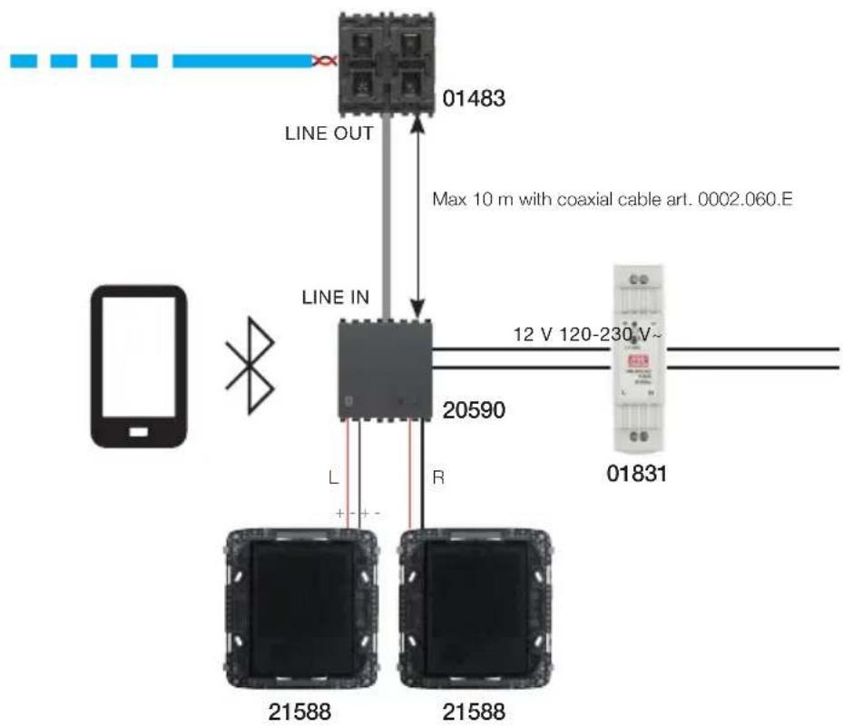
flowchart
graph TD
    A["Device"] -->|L| B["21588"]
    A -->|R| C["20590"]
    B --> D["Line IN"]
    C --> E["Line OUT"]
    D --> F["Max 10 m with coaxial cable art. 0002.060.E"]
    E --> G["12 V 120-230 V~"]
    H["Mobile Device"] --> I["Switch"]
    style A fill:#f9f,stroke:#333
    style B fill:#ccf,stroke:#333
    style C fill:#cfc,stroke:#333
    style D fill:#fcc,stroke:#333
    style E fill:#cff,stroke:#333
    style F fill:#ffc,stroke:#333
    style G fill:#cfc,stroke:#333
    style H fill:#fcc,stroke:#333
- The amplifier with integrated Bluetooth technology receiver 20590 is not connected to the speaker system bus, whereas control unit 01483 (connected to the amplifier 20590 via the LINE OUT) is connected to the bus.
- In this type of installation, the amplifier 20590 with Bluetooth technology receiver does not take up any of the 4 available channels of the speaker system.
- The amplifier 20590 with Bluetooth technology receiver is switched on and off using the pushbutton on the front of the device.
- By default, the audio signal on the Bluetooth technology receiver has priority over any input signal at the LINE IN.
Types of system
8.8 Bluetooth technology interface connected to the speaker system bus
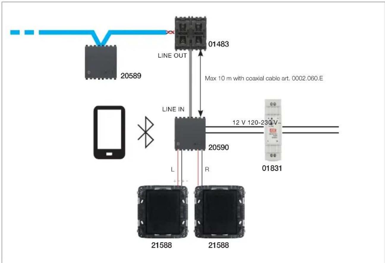
flowchart
graph TD
    A["Device 20589"] -->|Line OUT| B["Device 01483"]
    B -->|Line IN| C["Device 20590"]
    C -->|Max 10 m with coaxial cable art. 0002.060.E| D["Device 01831"]
    C -->|L| E["Device 21588"]
    C -->|R| F["Device 21588"]
    style A fill:#f9f,stroke:#333
    style B fill:#ccf,stroke:#333
    style C fill:#cfc,stroke:#333
    style D fill:#fcc,stroke:#333
    style E fill:#cff,stroke:#333
    style F fill:#ffc,stroke:#333
- The Bluetooth technology interface 20589 is connected to the speaker system bus and thus occupies one of the system's four channels.
- The Bluetooth technology interface 20589 can be switched on and off by the receivers on the bus according to the registration/deregistration logic, in the same way as other transmitters.
- The amplifier 20590 with Bluetooth technology receiver can if necessary be switched on and off using the pushbutton on the front of the device.
- By default, the audio signal on the Bluetooth technology receiver has priority over any input signal at the LINE IN. In practice, if an audio signal reaches the Bluetooth technology receiver of the amplifier 20590 while it is playing on LINE IN, the latter is muted, and the signal received via Bluetooth technology is played.
Types of system
8.9 Bluetooth technology interface connected to the speaker system bus and third-party amplifier

flowchart
graph TD
    A["Mobile Device 20589"] --> B["Line OUT"]
    B --> C["Line IN A"]
    C --> D["12 V 120-230 V"]
    D --> E["01831"]
    F["Max 10 m with coaxial cable art. 0002.060.E"] --> C
    G["A: Third party amplifiers with LINE IN input isolated from live parts"] --> H["L"]
    G --> I["R"]
- The Bluetooth technology interface 20589 is connected to the speaker system bus and thus occupies one of the system's four channels.
- The Bluetooth technology interface 20589 can be switched on and off by the receivers on the bus according to the registration/deregistration logic, in the same way as other transmitters.
- Third-party amplifiers play the audio signal that reaches the LINE IN input.
Glossary
9. Glossary
Source
Device playing an audio signal.
Transmission channel
Frequency band associated with a transmitter used to transmit the content of the source.
Transmitter (TX)
Device that sends the source content over the communication bus.
Receiver (RX)
Device that receives the source content from the bus and transmits it in the room via acoustic speakers.
Group
Set of functional block of the devices connected logically with each other.
Zone
One or more rooms in which the same sound source is played by one or more receivers.
Track
Saved song or radio station.
Section
Light Control
Table of contents
- General characteristics of the system.... 157
- Devices and functions 158
- Configuration on the controller 159
3.1 Functional unit selection and configuration 159
3.2 Setting/changing the parameters of the dimmers 160
3.2.1 WHITE dimmers.... 160
3.2.2 RGB dimmers 166
- Application examples 169
Presentation of the system
1. General characteristics of the system
The Light Control range, comprising universal dimmers and lamps, reconciles the need for comfort and a reduction in consumption, creating customized and "energy-frugal" environments, while ensuring full compatibility and total installation flexibility. The new range of universal dimmers allows you to manage every type of source, not just high energy efficiency sources, but also traditional incandescent sources. Control that is therefore also applicable to existing plants and provides the opportunity of fitting simply and effectively into any architecture.
Included in the By-me home automation system, the universal dimmers complete the light management range.
Using the touch screens will allow you to create and control the range of programmed lighting scenarios to make each room unique while paying attention to energy savings, by switching the lights on and off and adjusting their brightness. The new (patented) RGB functions, available via dedicated devices, enable making elegant, sophisticated colour changes and light effects, suitable for all needs, from residential to small businesses.
With the automation system you can then configure and afterwards call up scenarios involving various functions in the home automation system such as, for example, combinations of lights and colours matched with the audio functions to create customized environments featuring efficient and complete comfort.
All Vimar's solutions are part of a single universal technology that ensures "hassle-free" fittings and the ability to replace the old dimmers in existing systems, to ensure the utmost installation flexibility.
The universal dimmers are compatible with all light sources: incandescent bulbs, LEDs and dimmable compact fluorescent bulbs, halogen lights and LED strips. Dimming technology that is therefore ideal for any type of lighting system.
Total flexibility: this is the criterion with which the technology was chosen for all the new solutions for light management and control. In the case of both new plants and renovations, for fitting or replacement, it is possible at any time to choose more efficient and flexible sources, thanks to the devices that are technologically capable of dimming every kind of lamp.
Devices and functions
2. Devices and functions
The Light Control System consists of the following devices:
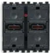 | 20529-19529-16969-14529: Two rocker switches and actuator for SLAVE dimmers 230 V~, for LED lamps, LED electronic transformers, RGB lamps, RGB electronic power supplies, to be completed with interchangeable buttons with 1 or 2 modules |
 | 20549-19549-16989-14549: Three rocker switches and MASTER dimmer actuator 230 V~ 50 Hz for incandescent lamps 40-300 W, electronic transformers 40-200 VA, CFL lamps 10-120 W, LED lamps 3-120 W, fuse, to be completed with interchangeable buttons with 1 or 2 modules - 3 mod-ules. |
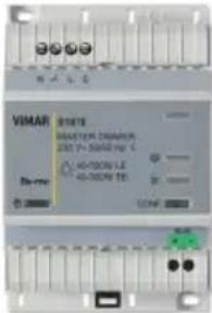 | 01870: MASTER dimmer 230 V~ 50/60 Hz for incandescent lamps 40-500 W, electronic transformers 40-300 VA, CFL lamps 10-200 W, LED lamps 3-200 W, for LED elec-tronic power supplies, protection fuse, installation on DIN rails (60715 TH35), occupies 4 modules size 17.5 mm. |
 | 01871: SLAVE dimmer 230 V~ 50/60 Hz for incandescent lamps 40-500 W, electronic transformers 40-300 VA, CFL lamps 10-200 W, LED lamps 3-200 W, control from universal MASTER dimmer with load adapter, fuse, installation on DIN rails (60715 TH35), occupies 4 modules size 17.5 mm. |
 | 01877: Electronic multi-voltage power supply 230 V~ 50 Hz for dimmable RGB LED lamps 12-24 V , adjustable with By-me devices. SELV output. |
Configuration on the controller
3. Configuration on the controller
The main task to perform in order to configure the dimmers of the Light Control system on the controller is to create functional groups (sets of functional units that need to work together) to which they are assigned.
CAUTION: ONLY ONE RGB ACTUATOR CAN BE CONFIGURED PER GROUP.
The procedure to be carried out for each new group is as follows:
Setup → Configuration → Groups
Automation groups → Add
Create the selected group:
- Index of new group (00-480) that identifies the number of the group in the list of all the configured ones; touch Next to confirm.
- New group name selecting, from among the names offered by a pre-set list, both the name of the group and the zone of application (necessary to distinguish between rooms and functions with the same name).
Lastly, proceed to save the name of the group by touching Save.
If the operation has been carried out correctly the control unit will show Operation completed successfully By selecting the desired group it is possible to view the information related to the group such as the address and number of devices, the devices that may already be linked and to delete the group (Remove Group menu).
3.1 Functional unit selection and configuration.
For each device, how to select a functional unit is explained in the instructions sheet that accompanies the product.
To configure the various functional units within a group, carry out the following:
- Tap Setup → Configuration → Groups → Automation Groups
- Select the name of the group to which you want to add the functional unit of the dimmer to configure.
- Select the group by scrolling through the list and tap Add; the procedure is started on the controller.
-
Select the type of dimmer (SLAVE dimmer or Other):
-
SLAVE dimmer → Next → (Phase Cutting) LE or TE → Next → (Flash start) Yes or No → End
-
Other Next WHITE or RGB Next
-
Press the configuration button and, where necessary, the rocker button of the dimmer to be included in the group.
If RGB and a rocker button has been selected in point 4, the controller will prompt you to set the function to be associated with the button too:
| RGB |
| Dimmer |
| Hue control |
| Saturation control |
| Fading Show Activation |
| Black Set |
Device parameters
Select the desired function by scrolling through the list and tap Set; the procedure is started on the controller.
-
The device indicates that configuration is in progress by means of a red LED, which goes off when configuration is complete.
-
The controller indicates the functional unit that has just been configured.
-
Proceed with the configuration of other functional units by repeating points 3, 4, 5 and 6 or tap Back to exit.

All the procedures relating to the management of the groups and functional units of the WHITE and RGB dimmers are similar to those of all the other By-me devices.
3.2 Setting/changing the parameters of the dimmers.
Device parameters can be set and/or modified in order to customize operation to adapt the system to the various installation requirements.
Setup → Configuration → Groups → Automation groups → Select the group by scrolling through the list → Associated devices → Select the functional unit by scrolling through the list → Device parameters

The modifiable parameters for each functional unit depend on the characteristics of the unit and vary by type depending on the dimmer considered.
3.2.1 WHITE dimmers
- Possible controls
- Switch on/off
- Adjust/change brightness
- Call up scenario
- Operating parameters
- Adjustment speed (minimum, normal, maximum)
- Minimum adjustment value
- Switch-on value
- Switch-on duration
- Switch-off duration
Device parameters
- Delay in switching off the dimmer with warning function
- Time for changing absolute brightness (Duration of absolute adj.)
- Phase cutting
- Flash start

flowchart
graph TD
    A["Device parameters\nSpeed Norm... Minumim Value 25% Switch on value > Switch on duration 00:02"] --> B["Switch on value\nLast value NO Initial value 25% Final value 100%"]
    A --> C["Device parameters\nSwitch off duration 00:02 Notice > Duration of absolute 00:02 Phase cutting LE"]
    C --> D["Notice\nNotice YES Notice delay 00:02 Notice value 50%"]
    A --> E["Black Save"]
    E --> F["Device parameters\nSwitch off duration 00:02 Notice > Duration of absolute 00:02 Phase cutting LE"]
    F --> G["Black Set"]
3.2.1.1 Speed of adjustment
This parameter allows you to set the speed (selectable from the Min, Norm and Max options) with which the adjustment is made via the associated device.
3.2.1.2 Minimum adjustment value
This parameter, to be used with CFLs, is used to set the minimum brightness value below which you cannot go.

line
| Position | Value | | -------- | ----- | | Start | 1 | | Mid | 0.5 | | End | 1 |Device parameters
3.2.1.3 Ramp Operation
This allows you to set the values of the brightness ramp both while switching on and off.

line
| Phase | Value | | ------------------ | ----- | | Start | Switch-on start value | | End | Switch-on end value || PARAMETER VALUES CAN BE SET | |
| Switch-on start value from 0% to 100% | |
| Switch-on end value from 0% to 100% | |
| Switch-on duration from 0 to 1 h | |
| Switch-off duration from 0 to 1 h | |
| Last value YES or NO |
If you select Last value → NO the Initial value and End value parameters will be displayed too.
Device parameters
3.2.1.4 Delayed switch-off with warning function
This parameter delays switching off while decreasing the brightness, if desired, for a set time (useful, for example, when you leave the house).

flowchart
graph TD
    A["Adjustment curve"] --> B["Warning adjustment"]
    B --> C["Delay switch-off"]
    B --> D["Duration switch-off"]
| PARAMETER VALUES CAN BE SET | |
| Switch Off Delay from 0 to 1 h | |
| Warning adjustment from 0% to 100% | |
Device parameters
3.2.1.5 Time for changing absolute brightness.
This parameter allows you to set the time it takes to change a value of absolute brightness (for example, due to the activation of a scenario).

flowchart
graph TD
    A["Current brightness value"] --> B["Desired brightness value"]
    B --> C["Duration adjustment"]
    C --> D["Adjustment curve"]
| PARAMETER VALUES CAN BE SET | |
| Duration of adjustment from 0 to 1 h |
3.2.1.6 Phase cutting
- Adjustment of leading edge (LE): used with incandescent lamps, compact fluorescent lamps and compatible LED lamps, as well as type electronic transformers.
- Adjustment of trailing edge (TE): used with compatible loads such as fluorescent lamps, LED lamps or type electronic transformers.
Dimmering with Leading Edge mode
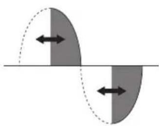
natural_image
Diagram showing two shaded regions with bidirectional arrows, separated by a horizontal line (no text or symbols)Dimmering with Trailing Edge mode

natural_image
Diagram showing two overlapping shaded regions with bidirectional arrows, separated by a horizontal line (no text or symbols)Device parameters
3.2.1.7 Flash Start
This parameter, used with CFLs, enables switching on at the maximum value for approximately 2 s and subsequent adjustment to the set value.

line
| Time (approx) | Adjustment Curve | | -------------- | ---------------- | | 0 | 1 | | ~1 | 1 | | ~2 | 1 | | ~3 | 1 | | ~4 | 1 | | ~5 | 1 | | ~6 | 1 | | ~7 | 1 | | ~8 | 1 | | ~9 | 1 | | ~10 | 1 | | ~11 | 1 | | ~12 | 1 | | ~13 | 1 | | ~14 | 1 | | ~15 | 1 | | ~16 | 1 | | ~17 | 1 | | ~18 | 1 | | ~19 | 1 | | ~20 | 1 | | ~21 | 1 | | ~22 | 1 | | ~23 | 1 | | ~24 | 1 | | ~25 | 1 | | ~26 | 1 | | ~27 | 1 | | ~28 | 1 | | ~29 | 1 | | ~30 | 1 | | ~31 | 1 | | ~32 | 1 | | ~33 | 1 | | ~34 | 1 | | ~35 | 1 | | ~36 | 1 | | ~37 | 1 | | ~38 | 1 | | ~39 | 1 | | ~40 | 1 | | ~41 | 1 | | ~42 | 1 | | ~43 | 1 | | ~44 | 1 | | ~45 | 1 | | ~46 | 1 | | ~47 | 1 | | ~48 | 1 | | ~49 | 1 | | ~50 | 1 | | ~51 | 1 | | ~52 | 1 | | ~53 | 1 | | ~54 | 1 | | ~55 | 1 | | ~56 | 1 | | ~57 | 1 | | ~58 | 1 | | ~59 | 1 | | ~60 | 1 | | ~61 | 1 | | ~62 | 1 | | ~63 | 1 | | ~64 | 1 | | ~65 | 1 | | ~66 | 1 | | ~67 | 1 | | ~68 | 1 | | ~69 | 1 | | ~70 | 1 | | ~71 | 1 | | ~72 | 1 | | ~73 | 1 | | ~74 | 1 | | ~75 | 1 | | ~76 | 1 | | ~77 | 1 | | ~78 | 1 | | ~79 | 1 | | ~80 | 1 | | ~81 | 1 | | ~82 | 1 | | ~83 | 1 | | ~84 | 1 | | ~85 | 1 | | ~86 | 1 | | ~87 | 1 | | ~88 | 1 | | ~89 | 1 | | ~90 | 1 | | ~91 | 1 | | ~92 | 1 | | ~93 | 1 | | ~94 | 1 | | ~95 | 1 | | ~96 | 1 | | ~97 | 1 | | ~98 | 1 | | ~99 | 1 | | >90 | <0 |Device parameters
3.2.2 RGB dimmers
- Possible controls
- Switch on/off
- Adjustment/change to hue (H)
- Adjustment/change to saturation (S)
- Adjustment/change to brightness (V)
- Call up scenario
- "FADING-SHOW"
- Operating parameters
- Adjustment speed (minimum, normal, maximum)
- Switch-on value
- Switch-on duration
- Switch-off duration
- Delay in switching off the dimmer with warning function
- Time for changing absolute brightness (Duration of absolute adj.)
- Setting "FADING-SHOW"

flowchart
graph TD
    A["Device parameters\nSpeed Norm\nSwitch on value >\nSwitch on duration 00:04\nSwitch off duration 00:02"] --> B["Switch on value\nLast value N0\nInitial value 25%\nFinal value 100%"]
    A --> C["Device parameters\nNotice N0\nDuration of absolute 00:02\nFadingshow >"]
    C --> D["Black Save"]
    B --> E["Black Set"]
The meaning of the parameters of Speed adjustment, Switch-on value, Switch-on duration, Switch-off duration, Delay in switching off the dimmer with warning function and Time for changing absolute brightness is similar to that for the WHITE dimmers.
Device parameters
3.2.2.1 Related adjustments
Using a previously configured rocker button you can adjust each of the following components:
Dimmer

natural_image
Gradient bar transitioning from dark gray to yellow-green with a small black triangle on the right (no text or symbols)Hue control

natural_image
Horizontal gradient bar transitioning from black triangle to rainbow (no text or symbols)Saturation control
natural_image
Simple graphic with a black triangle on a yellow gradient bar (no text or symbols)3.2.2.2 Fading-show
The Fading Show function allows you to actuate cyclical transitions in colour change and combinations thereof on the device.

flowchart
graph TD
    A["Device parameters\nNotice NO\nDuration of absolute 00:02\nFading Show"] --> B["Device parameters\nFading Show colors >\nTransition [min:s"] 00:12\nPersistence["min:s"] 00:33]
    B --> C["Device parameters\nFading Show colors >\nTransition [min:s"] 01:12\nPersistence["min:s"] 00:33]
    C --> D["Device parameters\nFading Show colors >\nTransition [min:s"] 01:12\nPersistence["min:s"] 00:33]
    D --> E["Back Save"]
Device parameters
Parameters:
- Duration of transition, that is the time elapsing between colour changes
- Duration of persistence, that is the time a single colour remains
- Colour list, that is the number of colours to be reproduced (up to a maximum of 6)
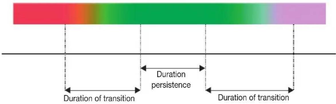
| PARAMETER VALUES CAN BE SET | |
| Duration of transition from 0 to 1 h | |
| Duration of persistence | from 0 to 1 h |
The fading-show mode is started with an on/off command.
| TYPE OF DEVICES FADING-SHOW FUNCTION | |
| By-me control devices YES | |
| Monochrome Touch Screens YES | |
| Colour Touch Screens | YES |
| Controllers NO | |
| Web Servers and applications YES | |
Application examples
4. Application examples
• Example 1
The following example shows the configuration of a control with two rocker buttons and an actuator for SLAVE dimmers 230 V\~ (20529-19529-14529) so you can control the brightness and fading-show in a room.

natural_image
Interior layout of a bedroom with a bed, wall-mounted unit, and an inset showing a close-up of the front panel (no text or symbols)The configuration will be made so that the left rocker button is associated with the brightness control and the right one with fading-show activation.
Creating functional groups.
Setup → Configuration → Groups → Automation groups → Add
Create the functional groups within which the various functional units are to be added.
Configuring the "actuator" functional unit.
-
Tap Setup → Configuration → Groups → Automation Groups
-
Select the name of the group to which you want to add the functional unit to configure.
-
Select the group by scrolling through the list and tap Add; the procedure is started on the controller.
-
Select Other → Next → RGB → Next
Press the device configuration button.
- The device indicates that configuration is in progress by means of a red LED, which goes off when configuration is complete. The controller will display the functional unit that has just been configured.
Configuring the "left button" functional unit.
-
Tap Setup → Configuration → Groups → Automation Groups
-
Select the name of the group to which you want to add the functional unit to configure.
Application examples
- Select the group by scrolling through the list and tap Add; the procedure is started on the controller.
- Select Other → Next → RGB → Next
Press the device configuration button and then the left rocker button.
- Select Dimmer → Set; the procedure is started on the controller.
- The device indicates that configuration is in progress by means of a red LED, which goes off when configuration is complete.
- The controller indicates the functional unit that has just been configured.
Configuring the "right button" functional unit.
- Tap Setup → Configuration → Groups → Automation Groups
- Select the name of the group to which you want to add the functional unit to configure.
- Select the group by scrolling through the list and tap Add; the procedure is started on the controller.
- Select Other → Next → RGB → Next
Press the device configuration button and then the right rocker button.
- Select Fading Show Activation → Set; the procedure is started on the controller.
- The device indicates that configuration is in progress by means of a red LED, which goes off when configuration is complete.
- The controller indicates the functional unit that has just been configured.
On pressing the right rocker button the fading show function will be activated as set in accordance with par. 3.2.2.2.
Application examples
- Example 2
The following example shows the configuration of a control with six pushbuttons 01485 which, combined with the power supply RGB 01877, is used to control the brightness, hue and saturation in a room.
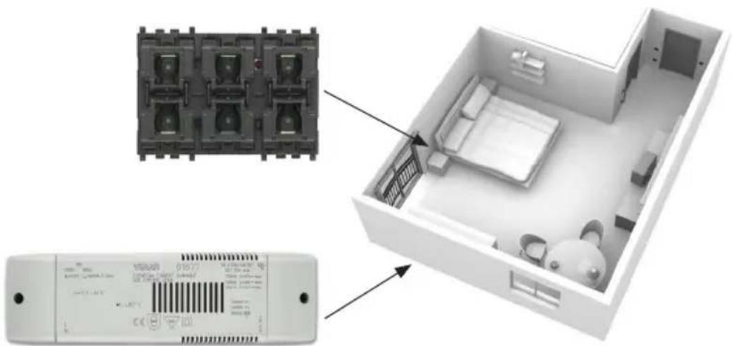
natural_image
Interior view of a home appliance showing internal components and a close-up of the interior layout (no text or symbols visible)The configuration will be made so that the left button is associated with the brightness control, the middle one with the hue and the right one with the saturation.
Creating functional groups.
Setup → Configuration → Groups → Automation groups → Add
Create the functional groups within which the various functional units are to be added.
Configuring the "power supply 01877" functional unit.
-
Tap Setup → Configuration → Groups → Automation Groups
-
Select the name of the group to which you want to add the functional unit to configure.
-
Select the group by scrolling through the list and tap Add; the procedure is started on the controller.
-
Select Other → Next → RGB → Next
Press the power supply CONF configuration button.
- The device indicates that configuration is in progress by means of a red LED, which goes off when configuration is complete. The controller will display the functional unit that has just been configured.
Application examples
Configuring the "left button" functional unit.
- Tap Setup → Configuration → Groups → Automation Groups
- Select the name of the group to which you want to add the functional unit to configure.
- Select the group by scrolling through the list and tap Add; the procedure is started on the controller.
- Select Other → Next → RGB → Next
Press the device configuration button and then the left rocker button.
- Select Dimmer → Set; the procedure is started on the controller.
- The device indicates that configuration is in progress by means of a red LED, which goes off when configuration is complete.
- The controller indicates the functional unit that has just been configured.
Configuring the "middle button" functional unit.
- Tap Setup → Configuration → Groups → Automation Groups
- Select the name of the group to which you want to add the functional unit to configure.
- Select the group by scrolling through the list and tap Add; the procedure is started on the controller.
- Select Other → Next → RGB → Next
Press the device configuration button and then the middle rocker button.
- Select Hue Control → Set; the procedure is started on the controller.
- The device indicates that configuration is in progress by means of a red LED, which goes off when configuration is complete.
- The controller indicates the functional unit that has just been configured.
Configuring the "right button" functional unit.
- Tap Setup → Configuration → Groups → Automation Groups
- Select the name of the group to which you want to add the functional unit to configure.
- Select the group by scrolling through the list and tap Add; the procedure is started on the controller.
- Select Other → Next → RGB → Next
Press the device configuration button and then the right rocker button.
- Select Saturation Control → Set; the procedure is started on the controller.
- The device indicates that configuration is in progress by means of a red LED, which goes off when configuration is complete.
- The controller indicates the functional unit that has just been configured.
Section
Power management
Table of Contents
- General features.... 175
- Devices and functions.... 176
- Load Control 178
3.1 Configuration of the load control module 01455 178
3.1.1 Installing the sensors 184
3.1.2 Setting the trigger thresholds 184
3.1.3 Creating control groups 187
3.1.4 Priority settings.... 187
3.1.5 Displaying the level of power consumed 188
3.1.6 Configuring a load cut-out signalling relay 188
3.1.7 Programming by time slots.... 188
3.1.8 Load operation control 188
3.2 Measurement control 189
3.3 Alarm control.... 190
3.4 Device parameters 190
Presentation of the system
1. General characteristics
The power management functions of the By-me system let you control the consumption of your system and see both instantaneous values and historical values of the electrical and other (water, gas) measurements.
The functions are grouped into three main menus:
-Load control: via the load control module 01455, it enables monitoring the amount of mains power being consumed in order to prevent the meter from being tripped due to overload and disconnecting the controlled loads according to priority, if necessary. Single-phase systems of up to 33 kW and three-phase systems of up to 100 kW can be managed with or without photovoltaic generation and with a maximum of 16 priority groups.
-Measurement control: allows you to use up to 20 By-me groups to configure power meters (art. 01450, 01451) or actuators (art. 01456, 20537-19537-14537) or pulse counting devices (art. 01452) in order to display the data on a By-me touch screen or web server.
-Alarm control: allows you to view the groups in which the actuators are configured with current measurement (art. 01456, 20537-19537-14537) and view/reset any alarms that may be signalled by the actuators themselves.
To check the power consumption, also in relation to any energy produced by a photovoltaic system, you need to install the load control module 01455 that is managed by the control panel on a par with the other appliance in the system.
The load control module 01455 can restore disconnected users automatically, as soon as the total consumption of the system returns to a level below the setting.
Devices and functions
2. Devices and functions
The devices that enable the Power Management functions are as follows:
 | 01450: Power meter, 3 inputs for toroidal current sensor, detectable power 25 W-100 kW, single-phase power supply 120-230 V 50/60 Hz three-phase 230/400 V 50/60 Hz, installation on DIN rail (60715 TH35), occupies 1 x 17.5 mm module. Supplied with a toroidal current sensor.The device measures the power on one or more mains lines.It can work on both single and three phase systems and can independently monitor up to 3 electrical lines.The current on the electrical line to be monitored is measured by a current sensor (art. 01457, 01458).Lastly, it saves the history of the energy values of each of the lines. |
 | 01451: Power meter with built-in current sensor, detectable power up to 3680 W, flush mounting (retrofit).The device measures the consumption of a load supplied by the electrical line. The consumption data such as power and energy dissipation are displayed on the touch screens (art. 21553.2, 21554, 21511.1, etc.) connected to the By-me bus. |
 | 01452: Pulse counter interface for detecting data from devices equipped with pulse output such as electricity, water, gas meters, with flush mounting (retrofit).The device enables counting the pulses transmitted by a fiscal meter or counter for gas, water, hot water, electricity, wind speed, etc. and puts the data collected onto the By-me bus.The pulse is reproduced on the output for other similar devices. |
Devices and functions
 | 01455: Load control module, 3 inputs for toroidal current sensor, detectable power 25 W-100 kW, single-phase power supply 120-230 V 50/60 Hz three-phase 230/400 V 50/60 Hz, installation on DIN rail (60715 TH35), occupies 1 17.5 mm module.The device prevents the switch in the electricity meter from tripping due to overload; it can operate on both single-phase and three-phase systems.The current on the electrical line to be monitored is measured with a current sensor (art. 01457, 01458) and it is capable of independently controlling up to 3 electrical lines.It is designed to control systems where there is also a generating plant (e.g. photovoltaic systems).If the line cable is not easily accessible, the measurement can be made remotely by means of the power meter (art. 01450) connected to the By-me bus.In addition, it saves the history of the energy values of each of the lines. |
 | 01456: Actuator with relay output 16 A 120-230 V~ 50/60 Hz with integrated current sensor, 1 input channel for toroidal residual current sensor, DIN rail installation (60715 TH35), occupies 1 17.5 mm module. Supplied without toroidal residual current sensor art. 01459.The device performs the function of an actuator and measures the power consumption; it also enables alarm signalling due to malfunctioning such as current leakage and load faults. The device can be used in automation, energy saving and HVAC management systems. It can also be used in systems where the old load control module 01855 is installed. |
 | 01457: Toroidal current sensor for load control and power metering, hole diameter 7.5 mm, cable length 40 cm. |
 | 01458: Toroidal current sensor for actuator 01456, hole diameter 19 mm, cable length 40 cm. |
 | 01459: Toroidal residual current sensor for power metering, hole diameter 9 mm, cable length 40 cm. |
 | 20537-19537-14537: Actuator with relay output 16 A 230 V ~ 50 Hz with integrated current sensor - 2 modules.The device performs the function of an actuator and measures the power consumption; it also enables alarm signalling due to malfunctioning such as current leakage and load faults. The device can be used in automation, energy saving and HVAC management systems. It can also be used in systems where the old load control module 01855 is installed. |
Load control
3. Load control
The load control module 01455 enables monitoring the amount of mains power being consumed in order to prevent the meter from being tripped due to overload and disconnecting the controlled loads, if necessary.
The following systems can be managed (with or without photovoltaic generation):
- single-phase systems up to 33 kW
- three-phase systems up to 100 kW
Up to 16 control groups can be controlled (equivalent to 16 priorities).
Each control group (which must necessarily include module 01455 and a By-me relay actuator) can be set in the following ways:
- Auto OFF/ON: automatic load connection and disconnection depending on the amount of power consumed and the group's priority
- Forced ON: load always on, irrespective of the input conditions.
- Forced OFF: load always off, irrespective of the input conditions.
For each group, you can from the control panel or touch screen select the Auto OFF/ONandForced ON mode setting; with the events programmes available on the control panel you can then set one or more groups in Forced OFF mode (typically used to time the activation/deactivation of specific loads).
Each group can be associated with a rocker switch, which can be used to force the setting to Forced ON (by pressing ON on the button); the override condition is indicated by the LED on the button, which remains lit continuously.
Pressing OFF on the group button takes you back to Auto OFF/ON mode.
3.1 Configuration of the load control module 01455
To configure this device carry out the following procedure:
Setup → Configuration → Groups → Power management → Load control → 374 Controller 01 → Associated devices → Add
Press the load control module configuration button.
Once the device has been recognised in the By-me control panel, you need to select the type of system. This is done by using a help menu that lets you configure the load control module in accordance with the wiring diagram and the required functions.
N.B. Configuration of the load control module 01455 can take up to a few minutes.
The following pages illustrate various types of system installation and the relevant configuration procedures.
Load control
■ Single-phase system with no generation
In this case you can simply use the load control module 01455 combined with a current sensor (see the figure on the next page).
In the help menu, select:
Type of system → Single-phase
Generation→ No
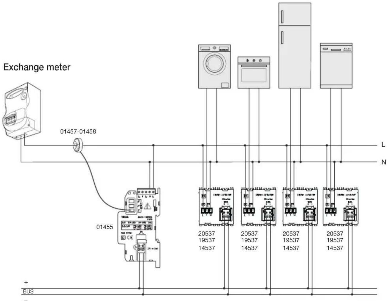
Load control
■ Single-phase system with "local" generation
In this type of system the cable leaving the generation meter goes to the same consumer unit where there is also the exchange meter cable.
In this case you can simply use just the load control module 01455 connecting the sensor 1 to the exchange meter and the sensor 2 to the generation meter as shown in the figure below.
In the help menu, select:
Type of system → Single-phase
Generation→Yes
Generation wiring→ Local wiring
Generation meter

flowchart
graph TD
    A["Solar Panel"] --> B["Inverter"]
    B --> C["L"]
    C --> D["N"]
    D --> E["01457-01458"]
    E --> F["01457-01458"]
    F --> G["Exchange meter"]
    G --> H["20537 19537 14537"]
    G --> I["20537 19537 14537"]
    G --> J["20537 19537 14537"]
    G --> K["20537 19537 14537"]
    H --> L["L"]
    I --> M["N"]
    J --> N["L"]
    K --> O["N"]
Load control
■ Single-phase system with “remote” generation
In this type of system the cable leaving the generation meter does not go to the same consumer unit where there is also the exchange meter cable.
Therefore, you cannot directly use the 2 current sensors on the load control module 01455 (the sensor cable is 40 cm long) but you need to install a power meter 01450 to measure the current generated (as shown in the figure below).
In the help menu, select:
Type of system → Single-phase
Generation→ Yes
Generation wiring→ Remote wiring
Exchange meter

flowchart
graph TD
    A["Power Source"] --> B["Generator 1"]
    A --> C["Generator 2"]
    A --> D["Generator 3"]
    E["Inverter"] --> F["Generation Meter"]
    G["Solar Panel"] --> F
    H["Bus"] --> I["Generator 4"]
    I --> J["Generator 5"]
    K["Bus"] --> L["Generator 6"]
    M["Bus"] --> N["Generator 7"]
    O["Bus"] --> P["Generator 8"]
    Q["Bus"] --> R["Generator 9"]
    S["Bus"] --> T["Generator 10"]
    U["Bus"] --> V["Generator 11"]
    W["Bus"] --> X["Generator 12"]
    Y["Bus"] --> Z["Generator 13"]
    AA["Bus"] --> AB["Generator 14"]
    AC["Bus"] --> AD["Generator 15"]
    AE["Bus"] --> AF["Generator 16"]
    AG["Bus"] --> AH["Generator 17"]
    AI["Bus"] --> AJ["Generator 18"]
    AK["Bus"] --> AL["Generator 19"]
    AM["Bus"] --> AN["Generator 20"]
    AO["Bus"] --> AP["Generator 21"]
    AQ["Bus"] --> AR["Generator 22"]
    AS["Bus"] --> AT["Generator 23"]
    AU["Bus"] --> AV["Generator 24"]
    AW["Bus"] --> AX["Generator 25"]
CAUTION: After configuring the load control module 01455, configure the functional unit no.1 of the power meter 01450 in the "375 Line 01" group by pressing the configuration button on the device once.
Load control
■ Three-phase system with no generation
In this case you can simply use the load control module 01455 combined with three current sensors (see the figure below).
In the help menu, select:
Type of system → Three-phase
Generation→ No
Exchange meter

Load control
■ Three-phase system with generation (from one to three phases)
In this case you need to use the load control module 01455 (paired with 3 current sensors) to measure the exchange current and the power meter 01450 to measure the generated current (with one current sensor for each phase of the generation meter).
In the help menu, select:
Type of system → Three-phase
Generation Yes
Select the lines to which the generation meter is connected; this selection will be highlighted with the icon √

flowchart
graph TD
    A["Solar Panel"] --> B["Generation Meter"]
    B --> C["Switch 01457-01458"]
    B --> D["Switch 01457-01458"]
    B --> E["Switch 01457-01458"]
    B --> F["Switch 01457-01458"]
    B --> G["Switch 01457-01458"]
    B --> H["Switch 01457-01458"]
    B --> I["Switch 01457-01458"]
    B --> J["Switch 01457-01458"]
    B --> K["Switch 01457-01458"]
    B --> L["Switch 01457-01458"]
    B --> M["Switch 01457-01458"]
    B --> N["Switch 01457-01458"]
    B --> O["Switch 01457-01458"]
    B --> P["Switch 01457-01458"]
    B --> Q["Switch 01457-01458"]
    B --> R["Switch 01457-01458"]
    B --> S["Switch 01457-01458"]
    B --> T["Switch 01457-01458"]
    B --> U["Switch 01457-01458"]
    B --> V["Switch 01457-01458"]
    B --> W["Switch 01457-01458"]
    B --> X["Switch 01457-01458"]
    B --> Y["Switch 01457-01458"]
    B --> Z["Switch 01457-01458"]
    B --> AA["Switch 01457-01458"]
    B --> AB["Switch 01457-01458"]
    B --> AC["Switch 01457-01458"]
    B --> AD["Switch 01457-01458"]
    B --> AE["Switch 01457-01458"]
    B --> AF["Switch 01457-01458"]
    B --> AG["Switch 01457-01458"]
    B --> AH["Switch 01457-01458"]
    B --> AI["Switch 01457-01458"]
    B --> AJ["Switch 01457-01458"]
    B --> AK["Switch 01457-01458"]
    B --> AL["Switch 01457-01458"]
    B --> AM["Switch 01457-01458"]
    B --> AN["Switch 01457-01458"]
    B --> AO["Switch 01457-01458"]
    B --> AP["Switch 01457-01458"]
    B --> AQ["Switch 01457-01458"]
    B --> AR["Switch 01457-01458"]
    B --> AS["Switch 01457-01458"]
    B --> AT["Switch 01457-01458"]
    B --> AU["Switch 01457-01458"]
    B --> AV["Switch 01457-01458"]
    B --> AW["Switch 01457-01458"]
    B --> AX["Switch 01457-01458"]
    B --> AY["Switch 01457-01458"]
    B --> AZ["Switch 01457-01458"]
    B --> BA["Switch 01457-01458"]
    B --> BB["Switch 01457-01458"]
    B --> BC["Switch 01457-01458"]
    B --> BD["Switch 01457-01458"]
    B --> BE["Switch 01457-01458"]
    B --> BF["Switch 01457-01458"]
    B --> BG["Switch 01457-01458"]
    B --> BH["Switch 01457-01458"]
    B --> BI["Switch 01457-01458"]
    B --> BJ["Switch 01457-01458"]
    B --> BK["Switch 01457-01458"]
    B --> BL["Switch 01457-01458"]
    B --> BM["Switch 01457-01458"]
    B --> BN["Switch 01457-01458"]
    B --> BO["Switch 01457-01458"]
    B --> BP["Switch 01457-01458"]
    B --> BQ["Switch 01457-01458"]
    B --> BR["Switch 01457-01458"]
    B --> BS["Switch 01457-01458"]
    B --> BT["Switch 01457-01458"]
    B --> BU["Switch 01457-01458"]
    B --> BV["Switch 01457-01458"]
    B --> BW["Switch 01457-01458"]
    B --> BX["Switch 01457-01458"]
    B --> BY["Switch 01457-01458"]
    B --> BZ["Switch 02637-26637"]
    B --> CA["Switch 26637-26637"]
    B --> CB["Switch 26637-26637"]
    B --> CC["Switch 26637-26637"]
    B --> CD["Switch 26637-26637"]
    B --> CE["Switch 26637-26637"]
    B --> CF["Switch 26637-26637"]
    B --> CG["Switch 26637-26637"]
    B --> CH["Switch 26637-26637"]
    B --> CI["Switch 26637-26637"]
    B --> CJ["Switch 26637-26637"]
    B --> CK["Switch 26637-26637"]
CAUTION: After configuring the load control module 01455, configure the power meter 01450 as follows:
- Insert functional unit no.1 of the power meter in the "Line 1" group pressing the configuration button once
- Insert functional unit no.2 of the power meter in the "Line 2" group pressing the configuration button twice *
- Insert functional unit no.3 of the power meter in the "Line 3" group pressing the configuration button three times **
N.B: * required if the generation meter is also connected to line 2 in the system.
** required if the generation meter is also connected to line 3 in the system.
3.1.1 Installing the sensors
There are two types of sensors that can be used and configured in the Power Management system:
- 01457: 7.5 mm Toroidal Sensor
- 01458: 19 mm Toroidal Sensor
3.1.1.1 Physical installation of the sensors
IMPORTANT: 01457 and 01458 type sensors must be installed by facing the side on which the distinctive label is glued towards the fiscal meter or the meter associated with generation.

natural_image
Line drawing of a cable and electrical connector assembly (no text or symbols)3.1.1.2 Setting the sensors on devices art. 01455 and 01450
IMPORTANT: When you install a sensor in art. 01455 and 01450 (new installation or replacement of an existing one), you must associate the device that is to use this sensor with the characteristic parameter shown on the label; the procedure is as follows.
• Physically connect the sensor to the input S1, S2 or S3 of the device (art. 01455 or 01450)
- Setup → Configuration → Groups → Power management → Load control* or Measurement control** → Select the desired metering functional unit → Device parameters → Sensor setting
- select the type of sensor (01457, 01458) → Set
- enter the "calibration" value (in the example shown in the figure, this value is 123) specified on the sensor label → Set
Lastly select Save and the control panel will return to the menu Device parameters
* If the functional unit belongs to a Load Control group
** If the functional unit belongs to a Measurement Control group
3.1.2 Setting the trigger thresholds
After configuring the load control module 01455 and, where applicable, the power meter 01450, you need to set the system's trigger thresholds and response times.
In the case of systems with an electronic meter with a domestic contract, set the parameters (referring to the values stated in the contract) as shown in the following example.
Load control
Assuming you have a supply with the following characteristics:
- single-phase system
- nominal contract power: 3 kW; a level of power 10% higher than the nominal contract power can be consumed for an unlimited period (3.3 kW in this case);
• maximum power usable for a limited period: 4.2 kW;
• maximum period for which maximum power can be used: 3 hours.
You can set the values in the By-me control panel:
- first threshold: 3.2 kW;
• second threshold at the maximum power value: 4.1 kW;
- validity period for the second threshold: 90 minutes.
IMPORTANT: If the meter is electronic, the contract thresholds must always be checked with the electricity supplier.
CAUTION: If in doubt, check the values by contacting the customer assistance service of your electricity provider.
To compensate for any potential measurement errors and synchronization between the load control logic and the fiscal meter, the value of each of the two thresholds must be less than the threshold required by the fiscal meter
■ Single-phase system
To set the thresholds for controlling the power consumed and the threshold time, follow the procedure below:
Power management → Load control → Setup → Setting thresholds
Select the threshold (Threshold 1 [kW], Threshold 2 [kW]) that you want to set and enter the desired value; confirm with Set and at the end of the operation touch Save.
The control panel confirms the operation has been completed.
In a similar manner the Threshold time is set too; enter the desired value and confirm with Set → Save
Note: After the Set step, entering the desired value can condition also the other power setup fields, automatically setting the minimum value.
If you want to zero out the operation time, set Threshold 1= Threshold 2.
■ Three-phase system
To set the thresholds for controlling the power consumed and the threshold time for the entire system, follow the procedure below:
Power management → Load control → Setup → Setting thresholds → Global threshold
Select the threshold (Threshold 1 [kW], Threshold 2 [kW]) that you want to set and enter the desired value; confirm with Set and at the end of the operation touch Save.
The control panel confirms the operation has been completed.
Load control
In a similar manner the Threshold time is set too; enter the desired value and confirm with Set → Save
Note: After the Set step, entering the desired value can condition also the other power setup fields, automatically setting the minimum value.
To set thresholds for the single lines of the three-phase system, first select the desired line:
Power management → Load control → Setup → Setting thresholds → Threshold line 1 or
Power management Load control Setup Setting thresholds Threshold line 2 or
Power management → Load control → Setup → Setting thresholds → Threshold line 3
Lastly set the desired threshold values and confirm with Set → Save
Important: If the values of "Threshold 1", "Threshold 2 and "Threshold Time" have been set, as soon as the consumed power exceeds "Threshold 1" (P > Threshold 1) the sensor is able to ensure absorption up to a value of "Threshold 2" for a time equal to the "Threshold Time" and disconnecting any loads (according to the set priorities) to bring the consumed power back to a lower value than "Threshold 2" (P < Threshold 2).
After the "Threshold Time" the maximum power that can be drawn is limited to the value of "Threshold 1" for the set time (P < Threshold 1) disconnecting any loads (according to the priorities); at the end of the "Threshold Time" the cycle starts again.
If you want to zero out the operation time, set Threshold 1= Threshold 2.
The diagram below illustrates an example of how the loads get disconnected according to the set thresholds and threshold times.

line
| Time (min) | Power (kW) | |---|---| | Ts2 | 1500 | | Ts2 | -1000 | | Ts2 | -1500 | | Ts2 | -1000 | | Ts2 | -1500 | | Ts2 | -1000 | | Ts2 | -1500 | | Ts2 | -1000 | | Ts2 | -1500 | | Ts2 | -1000 | | Ts2 | -1500 | | Ts2 | -1000 | | Ts2 | 1500 | | Ts2 | 1000 | | Ts2 | 1500 | | Ts2 | 1000 | | Ts2 | 1500 | | Ts2 | 1000 | | Ts2 | 1500 | | Ts2 | 1000 | | Ts2 | 1500 | | Ts2 | 1000 | | Ts2 | 1500 | | Ts2 | -1500 | | Ts2 | -1000 | | Ts2 | -1500 | | Ts2 | -1000 | | Ts2 | -1500 | | Ts2 | -1000 | | Ts2 | -1500 | | Ts2 | -1000 | | Ts2 | -1500 | | Ts2 | -1500 | | Ts2 | -1500 | | Ts2 | -1500 | | Ts2 | -1500 | | Ts2 | -1500 | | Ts2 | -1500 | | Ts2 | -1500 | | Ts2 | -1500 | | Ts2 | -1500 | | Ts2 | -1700 | | Ts2 | -1500 | | Ts2 | -1500 | | Ts2 | -1500 | | Ts2 | -1500 | | Ts2 | -1500 | | Ts2 | -1500 | | Ts2 | -1500 | | Ts2 | -1500 | | Ts2 | -1500 | | Ts2 | -1877 | | Ts2 | -1500 | | Ts2 | -1500 | | Ts2 | -1500 | | Ts2 | -1500 | | Ts2 | -1500 | | Ts2 | -1500 | | Ts2 | -1877 | | Ts2 | -1500 | | Ts2 | -1500 | | Ts2 | -1506 | | Ts2 | -1506 | | Ts2 | -1506 | | Ts2 | -1506 | | Ts2 | -1506 | | Ts2 | -1506 | | Ts2 | -1877 | | Ts2 | -1506 | | Ts2 | -1506 | | Ts2 | -1506 | | Ts2 | -1506 | | Ts2 | -1877 | | Ts2 | -1506 | | Ts2 | -1506 | | Ts2 | -1877 | | Ts2 | -1506 | | Ts2 | -1877 | | Ts2 | -1877 | | Ts2 | -1877 | | Ts2 | -1877 | | Ts2 | -3497 Tint<2 LOAD CONTROL TRIGGERS + P1: WASHING MACHINE (+ 1500 W) + P2: OVEN (+ 1500 W) LOAD CONTROL TRIGGERS + P1: WASHING MACHINE (+ 1500 W) LOAD CONTROL TRIGGERS + P1: WASHING MACHINE (+ 150W) LOAD CONTROL TRIGGERS + P1: WASHING MACHINE (+ 15W) LOAD CONTROL TRIGGERS + P1: WASHING MACHINE (+ 15W) LOAD CONTROL TRIGGERS + P1: WASHING MACHINE (+ 15W) LOAD CONTROL TRIGGERS + P1: WASHING MACHINE (+ 15W) LOAD CONTROL TRIGGERS + P1: WASHING MACHINE (+ 15W) LOAD CONTROL TRIGGERS + P1: WASHING MACHINE (+ 1877 W) LOAD CONTROL TRIGGERS + P1: WASHING MACHINE (+ 1877 W) LOAD CONTROL TRIGGERS + P1: WASHING MACHINE (+ 1877 W) LOAD CONTROL TRIGGERS + P1: WASHING MACHINE (+ 1877 W) LOAD CONTROL TRIGGERS + P1: WASHING MACHINE (+ 1877 W) LOAD CONTROL TRIGGERS + P1: VASHING MACHINE (+ 15W) + P2: OVEN (+ 15W) LOAD CONTROL TRIGGERS + P1: VASHING MACHINE (+ 15W) LOAD CONTROL TRIGGERS + P1: VASHING MACHINE (+ 15W) LOAD CONTROL TRIGGERS + P1: VASHING MACHINE (+ 18W) LOAD CONTROL TRIGGERS + P1: VASHING MACHINE (+ 18W) LOAD CONTROL TRIGGERS + P1: VASHING MACHINE (+ 18W) LOAD CONTROL TRIGGERS + P1: VASHING MACHINE (+ 18W) LOAD CONTROL TRIGGERS + P1: VASHING MACHINE (+ 18W) LOAD CONTROL TRIGGERS + P1: VASHING MACHINE (+ 15W) LOAD CONTROL TRIGGERS + P1: VASHING MACHINE (+ 18W) LOAD CONTROL TRIGGERS + P1: VASHING MACHINE (+ 18W) LOAD CONTROL TRIGGERS + P1: VASHING MACHINE (+ 18W) LOAD CONTROL TRIGGERS + P1: VASHING MACHINE (+ 15W) LOAD CONTROL TRIGGERS + P1: VASHING MACHINE (+ 15W) LOAD CONTROL TRIGGERS + P1: VASHING MACHINE (+ 18W) LOAD CONTROL TRIGGERS + P1: VASHING MACHINE (+ 18W) LOAD CONTROL TRIGGERS + P1: VASHING MACHINE (+ 15W) LOAD CONTROL TRIGGERS + P1: VASHING MACHINE (+ 18W) LOAD CONTROL TRIGGERS + P1: VASHING MACHINE (+ 15W) LOAD CONTROL TRIGGERS + P1: VASHING MACHINE (+ 877 W) LOAD CONTROL TRIGGERS + P1: VASHING MACHINE (+ 877 W) LOAD CONTROL TRIGGERS + P1: VASHING MACHINE (+ 877 W) LOAD CONTROL TRIGGERS + P1: VASHING MACHINE (+ 877 W) LOAD CONTROL TRIGGERS + P1: VASHING MACHINE (+ 877 W) LOAD CONTROL TRIGGERS + P1: VASHING MACHINE (- 877 W) LOAD CONTROL TRIGGERS + P1: VASHING MACHINE (- 877 W) LOAD CONTROL TRIGGERS + P1: VASHING MACHINE (- 877 W) LOAD CONTROL TRIGGERS + P1: VASHING MACHINE (- 877 W) LOAD CONTROL TRIGGERS + P1: VASHING MACHINE (- 877 W) LOAD CONTROL TRIGGERS + P1/VOEN (- 877 W) LOAD CONTROL TRIGGERS + P2: OVEN (- 877 W) LOAD CONTROL TRIGGERS + P2: OVEN (- 877 W) LOAD CONTROL TRIGGERS + P2: OVEN (- 877 W) LOAD CONTROL TRIGGERS + P2: OVEN (- 877 W) LOAD CONTROL TRIGGERS + P2: OVEN (- 877 W) LOAD CONTROL TRIGGERS + P2: OVEN (- 873 W) LOAD CONTROL TRIGGERS + P2: OVEN (- 873 W) LOAD CONTROL TRIGGERS + P2: OVEN (- 873 W) LOAD CONTROL TRIGGERS + P2: OVEN (- 873 W) LOAD CONTROL TRIGGERS + P2: OVEN (- 873 W) LOAD CONTROL TRIGGERS + P2: OVEN (- 873 W) LOAD CONTROLTRIGGERS + P2: OVEN (- 873 W) LOAD CONTROLTRIGGERS + P2: OVEN (- 873 W) LOAD CONTROLTRIGGERS + P2: OVEN (- 873 W) LOAD CONTROLTRIGGERS + P2: OVEN (- 873 W) LOAD CONTROLTRIGGERS + P2: OVEN (- 873 W) LOAD CONTROLTRIGGERS +P2: OVEN (- 873 W) LOAD CONTROLTRIGGERS +P2: OVEN (- 873 W) LOAD CONTROLTRIGGERS +P2: OVEN (- 873 W) LOAD CONTROLTRIGGERS +P2: OVEN (- 873 W) LOAD CONTROLTRIGGERS +P2: OVEN (- 873 W) LOAD CONTROLTRIGGERS +P2: OVEN(- 873 W) LOAD CONTROLTRIGGERS +P2: OVEN(- 873 W) LOAD CONTROLTRIGGERS +P2: OVEN(- 873 W) LOAD CONTROLTRIGGERS +P2: OVEN(- 873 W) LOAD CONTROLTRIGGERS +P2: OVEN(- 873 W) LOAD CONTROLTRIGGERS +P2: OVEN(- 873 G)4Load control
3.1.3 Creating control groups
The Load Control system command groups are the groups that contain the actuators that supply the various loads that you want to control.
Setup → Configuration → Groups → Power management → Load control → Select one of the groups from "Relay 01" to "Relay 16" → Associated devices → Add
Within a control group you need to configure a By-me relay actuator and a functional unit governing the load control module (to configure one, after the first configuration of the module, simply press the configuration button again to activate the usual procedure from the selected group).
Each group can also contain a rocker switch, which can be used to force the group relay(s) to ON, irrespective of the priority set in the load conditions.
N.B.
- In the Load Control group it is essential to configure module 01455 so it can be displayed on the control panel.
- The load must be connected on terminal C-NO of the relay actuator.
Appliances such as refrigerators or freezers, which need to be powered continuously, must be connected to uncontrolled power outlets.
For other devices, set a priority value of 1 (the highest) for the more important loads (these will be disconnected last), and higher priority number for the loads to be disconnected first.
Press the configuration buttons of the load control module 01455, of the relay actuator governing the oven and if necessary add a button for forcing.
3.1.4 Priority settings.
To set or modify the priority value of a group, follow the procedure below:
Power management Load control Setup Priority settings Scroll through of configured load groups and select the desired one

Select the priority from among the ones available (from P1 to P16) and then confirm with Set.
Note: In the case of a three-phase system with loads associated with more than one line, the logic of the device 01455 can trigger cutting off a higher-priority load than another load; the priority is unique for all the lines and the logic switches it off due to overload on a line always starting with the load with the lowest priority.
Lastly save the settings with Save; the control panel will confirm the operation.
CAUTION!
- When creating groups, the control panel assigns priority 1 (P1) to the first group, 2 (P2) to the second group and so on; it is however possible to change the values of the priorities at any time.
- The priorities of the groups must be different from each other. If two or more groups are incorrectly configured at the same priority level, the Load Control device will determine the priority according to the group number (the lowest value will have the highest priority).
Load control
3.1.5 Displaying the level of power consumed.
With the control panel you can at any time view the instantaneous power consumed by the system. Furthermore, if the system is also monitoring a production plant, the instantaneous power generated in the system will be displayed. The consumption value displayed in the middle corresponds to the actual consumption of the system, regardless of the actual values of any production.
Main menu → Power management → Load control
| Load control | 12:00 |
| Consumption: | 10.2 KW |
| Generation: | 10.2 KW |
| Back | Setup |
The control panel displays the power in kW; to display load status and modify operation, tap Operation

Setup →
3.1.6 Configuring a load cut-out signalling relay
The load control module can be associated with relays to signal whether one or more loads have been disconnected according to the set priorities.
The relay can be configured in the "Provider 01" group if you want to signal any load being cut off on any line (in the case of a three-phase system).
It is also possible to associate the relay with the "Line 1" or "Line 2" or "Line 3" groups to have the cut-off of one of the groups belonging to the single line signalled.
Setup → Configuration → Groups → Power management → Load control → Select the desired group → Associated devices → Add
3.1.7 Programming by time slots
The By-me system Load Control function can be used to manage loads during certain times of the day, i.e. to set the time slots during which one or more of the 16 groups dedicated to load control will be activated or switched off. To do this it is necessary to create a specific weekly time programme indicating at what times of the various days of the week the loads must be in Forced OFF mode and in which the control must be of the type Auto OFF/ON. The weekly time program must have no input group; one or two load control groups must be selected for the program output.
3.1.8 Load operation control.
The load control management mode can be decided for each group by selecting Automatic, Forced ON and Forced OFF.
- Automatic: The load is disconnected automatically depending on the priority assigned and reconnected automatically when the power consumption falls below the set threshold;
- Forced ON: The power outlet is always supplied.
- Forced OFF: The power outlet is never supplied;
Tapping Power management → Load control → Setup → Operation displays the state of the loads and allows you to change their operation.
Load control
By selecting the desired load, it is possible to set the type of management to carry out (Automatic, Forced ON and Forced OFF).
3.2 Measurement control
With the Measurement Control function you can use up to 20 By-me groups to configure 01450, 01451, 01452 power meters to monitor the consumption of lines, single loads and meters with pulse outputs; on By-me touch screens and web servers, in addition to the instantaneous values, you can then also view the historical consumption trend. For more details please refer to the relevant user manuals.
On each group you can configure a single functional unit for measuring or pulse counting.
New groups are created and devices added with the usual procedures described in the Configuration menu. In a single-phase system with no generation it is possible to use the current sensors 2 and 3 of the load control module 01455 or, in the a single-phase system with local generation, only the current sensor 3 (in this case the sensor 2 is used for the generation).
In a single-phase system with no local generation there is the advantage of being able to configure the Meter 3 of the load control module and where applicable Meter 2. This allows you to have one or two "auxiliary measurements" to see the power of any load to be monitored without being obliged to buy an additional measuring device.
The products that can be configured in the measurement control groups are the following:
• POWER METER art. 01450
To configure press:
-once on the device configuration button to configure the functional unit linked with line 1 (S1)
-twice on the device configuration button to configure the functional unit linked with line 2 (S2)
-three times on the device configuration button to configure the functional unit linked with line 3 (S3)
CAUTION: You cannot configure a functional unit if it is already used to control loads.
N.B. Configuration of the meter 01450 can take up to a minute.
• ACTUATOR WITH CURRENT SENSOR art. 01456, 20537-19537-14537
To configure the actuator measurement functional unit press the device configuration button twice.
- POWER METER WITH BUILT-IN CURRENT SENSOR art. 01451
To configure the actuator measurement functional unit press the device configuration button once.
• PULSE COUNTER INTERFACE art. 01452
To configure the actuator measurement functional unit press the device configuration button once.
When the above-listed devices have been configured via the menu:
Power management → Measurement control
On selecting the desired group you can see:
- the instantaneous power (in the case of meters on products 01450, 01451, 01456, 20537-19537-14537)
- the value of the measured variable (in the case of the pulse counter 01452).
Load control
3.3 Alarm control
With this menu you can view the alarms associated with each measuring group and if necessary reset the leakage alarm on those devices that support it.
Main Menu → Power management → Alarm control → Select the desired group → Select the device → Select the alarm → Reset

flowchart
graph TD
    A["Power management"] --> B["Alarm control"]
    B --> C["Back"]
    D["Associated relay"] --> E["Diagnostic smart relay"]
    E --> F["Back"]
    B --> G["--- No group\n80 Stair light\n380 Washing machine\n381 Oven"]
    E --> H["Back"]
    I["Load control\nMeasurement control\nAlarm control"] --> B
    J["Smart relay\n0x2202"] --> E
    K["Diagnostic smart rel\n0x2205"] --> E
    L["Load failure\nCurrent leakage"] --> M["OK"]
    N["Reset"] --> O["Back"]
3.4 Device parameters
For each of the devices, the settings that can be configured directly by the control panel are as follows:
• POWER METER art. 01450
■ Measurement refresh duration: time interval during which the power meter sends the power values to a display device (such as a touch screen) with a frequency equal to the set "Measurement refresh frequency". Values can be set from 20 to 120 s.
■ Measurement refresh frequency: frequency with which the power meter, during the "Measurement refresh duration" time interval, sends the power values of the display device (such as a touch screen). Values can be set from 1 to 10 s.
■ Reset value: allows you to set the initial value of the measured power which will then be updated as time passes.
■ Sensor setting: displays a screen that allows you to set:
- the Type of sensor → Select the article code number for the sensor (for instance, art. 01457)
- the Calibration → Enter the value shown on the sensor's label (for instance, 40E)
Confirm with Set and save with Save.
• SINGLE LOAD CONSUMPTION METER art. 01451
■ Measurement refresh duration: time interval during which the power meter sends the power values to a display device (such as a touch screen) with a frequency equal to the set "Measurement refresh frequency". Values can be set from 20 to 120 s.
Load control
■ Measurement refresh frequency: frequency with which the power meter, during the "Measurement refresh duration" time interval, sends the power values of the display device (such as a touch screen). Values can be set from 1 to 10 s.
■ Reset value: allows you to set the initial value of the measured power which will then be updated as time passes.
• PULSE COUNTER INTERFACE art. 01452
■ Divider: typical pulse generator parameter. Values can be set from 1 to 65535.
■ Multiplier: typical pulse generator parameter. Values can be set from 1 to 65535.
■ Minimum pulse duration: minimum detectable pulse duration. Values can be set from 2 to 250 ms.
■ Variable: used to select the physical variable to measure (water, gas, etc.).
■ Reset value: used to set the initial value to which the Pulse Counter Interface 01452 adds the number of the following pulses it has detected.
- LOAD CONTROL MODULE art. 01455
■ Load cut-off priority: enables setting the priority and therefore the order with which control groups are to be cut off. Values can be set from P1 to P16 (all different from each other).
■ Cut-off thresholds/Single line thresholds: two thresholds S1 and S2 (with S2 greater than or equal to S1) for the entire system and two thresholds for the single line. These are the reference levels for the power consumption that determine cutting off loads; they must be configured according to the characteristics of the supply contract. Values that can be set:
- S1: from 2.0 to 135.0 kW.
- S2: from 2.0 to 150.0 kW.
■ Highest threshold validity time (and on the single line): reference time for the validity of the highest threshold used for cutting off loads; it must be configured according to the characteristics of the supply contract. Values can be set from 20 to 200 min.
■ Measurement refresh duration: time interval during which the power meter sends the power values to a display device (such as a touch screen) with a frequency equal to the set "Measurement refresh frequency". Values can be set from 20 to 120 s.
■ Measurement refresh frequency: frequency with which the power meter, during the "Measurement refresh duration" time interval, sends the power values of the display device (such as a touch screen). Values can be set from 1 to 10 s.
■ Associated lines: line to which the load you want to control is connected.
■ Generation Threshold: minimum threshold of net power generated (that is in excess of the power consumed) above which it is possible to power the load. Values can be set from 0 (can always be activated) to 33.0 kW.
N.B. By properly configuring this parameter you can optimize power management from the perspective of auto-consumption.
It is advisable to use this feature by linking it to the value of the Minimum switch-on time parameter. In this way, the load control logic will allow switching on the load only with the set generated power and, even if it should then drop, it will keep the load in operation according to the set minimum time. Throughout this time, however, the overload shutdown control will remain active.
Load control
■ Minimum switch-on time: the load, once switched on, must remain ON for the Minimum switch-on time. Values can be set from 0 to 300 min.
■ Minimum switch-off time: the load, once switched off, must remain OFF for the Minimum switch-off time. Values can be set from 0 to 300 min.
• RELAY ACTUATOR art. 01456
■ Failure alarm mode: used to enable the failure alarm. Values that can be set: 0 = alarm disabled, 1 = alarm enabled.
Note: The failure alarm must only be enabled on actuators to which are connected loads that have a constant minimum consumption; otherwise, there would be the risk of false alarms due to a load that does not consume not because of failure but because its ON operation is not always constant.
■ Failure alarm threshold: minimum power value below which a failure alarm is signalled. Values can be set from 0 to 100 Watts.
■ Mode: actuator operating mode that can be selected from Monostable (return to OFF after ON duration seconds) or Bistable (state change with external command). Values that can be set: 0 = Bistable, 1 = Monostable.
■ Leakage alarm mode: leakage alarm operating mode. Settable values 0 = Alarm Disabled and reset, 1 = Alarm Enabled, i.e. the actuator status is constrained to the value of Auto OFF.
■ Leakage alarm threshold: minimum leaked current value above which there is a “current leakage” alarm signal. Values can be set from 0 to 50 mA.
■ ON delay: delay in activating the ON command. During the ON delay standby phases, a command that maintains this status resets the meters while an opposite command has no effect on meter initialization. Values can be set from 0 to 11h 59min 59s.
■ OFF delay: delay in activating the OFF command. During the OFF delay standby phases, a command that maintains this status resets the meters while an opposite command has no effect on meter initialization. Values can be set from 0 to 11h 59min 59s.
■ ON duration: time for which the device is on; at the end of the set time the device switches off and sends the information on its status. It should only be taken into account on actions concerning theTimedStart-Stop and DimmingInput commands that determine the MONOSTABLE behaviour of the actuator. Values can be set from 0 to 11h 59min 59s.
■ Auto off: Enables or disables the device's relay automatic switch-off feature in the event of a leakage alarm; it is constrained by Leakage alarm mode=1. Values that can be set: 0=Auto off disabled, 1=Auto off enabled.
■ Scenario delay: delay in actuating the scenario. Values can be set from 0 to 10 s.
Note: This parameter is used when in actuating a scenario there is to be the simultaneous activation of different actuators. To avoid a high inrush current due to switching on multiple devices simultaneously, the actuators are activated in rapid sequence, each with a default delay time (Scenario Delay) after receiving the command; the entire activation sequence can then take up to approximately 1 hour and 50 minutes. During the standby phase PAR_ScenarioDelay, receiving a group command, type SwitchOnOff, DimmingInput, TimedStartStop, resets the meter inhibiting activation of the scenario.
Load control
• ACTUATOR WITH RELAY OUTPUT art. 20537-19537-14537
■ Failure alarm mode: used to enable the failure alarm. Values that can be set: 0 = alarm disabled, 1 = alarm enabled.
Note: The failure alarm must only be enabled on actuators to which are connected loads that have a constant minimum consumption; otherwise, there would be the risk of false alarms due to a load that does not consume not because of failure but because its ON operation is not always constant.
■ Failure alarm threshold: minimum power value below which a failure alarm is signalled. Values can be set from 0 to 100 Watts.
■ Mode: actuator operating mode that can be selected from Monostable (return to OFF after ON duration seconds) or Bistable (state change with external command). Values that can be set: 0 = Bistable, 1 = Monostable.
■ ON delay: delay in activating the ON command. During the ON delay standby phases, a command that maintains this status resets the meters while an opposite command has no effect on meter initialization. Values can be set from 0 to 11h 59min 59s.
■ OFF delay: delay in activating the OFF command. During the OFF delay standby phases, a command that maintains this status resets the meters while an opposite command has no effect on meter initialization. Values can be set from 0 to 11h 59min 59s.
■ ON duration: time for which the device is on; at the end of the set time the device switches off and sends the information on its status. It should only be taken into account on actions concerning theTimedStart-Stop and DimmingInput commands that determine the MONOSTABLE behaviour of the actuator. Values can be set from 0 to 11h 59min 59s.
■ Scenario delay: delay in actuating the scenario. Values can be set from 0 to 10 s.
Note: This parameter is used when in actuating a scenario there is to be the simultaneous activation of different actuators. To avoid a high inrush current due to switching on multiple devices simultaneously, the actuators are activated in rapid sequence, each with a default delay time (Scenario Delay) after receiving the command; the entire activation sequence can then take up to approximately 1 hour and 50 minutes. During the standby phase PAR_ScenarioDelay, receiving a group command, type SwitchOnOff, DimmingInput, TimedStartStop, resets the meter inhibiting activation of the scenario.
Section
Tactil Devices
Table of Contents
- General characteristics of the system 197
- Devices and functions.... 197
- Configuration on the controller 197
3.1 Functional unit selection and configuration 198
3.2 Functional units of devices 198
3.2 Setting/changing the parameters 199
System Features - Devices and Functions
1. General system characteristics
The Tactil system is designed for the use of touch controls, completely made of glass, to perform the functions normally carried out by the buttons and rocker buttons of the By-me system. The device's RGB LEDs can also be rendered independent of the respective button and used as a signalling LED (actuator operation).
Marked by a high technological content, the devices should be completed with glass cover plates, which are available in four colour variants and distinguished by extreme sophistication teamed with extraordinary hard-wearing resistance.
To be activated, a gentle touch is sufficient, and the sophisticated technology transforms it into direct energy control; indeed, as soon as they are touched, a proximity sensor detects proximity to the device and activates the RGB LED backlighting integrated into the system. Moreover, once the push button is pressed, a dedicated acoustic signal confirms the button has been pressed.
Available in the 2- and 3-module versions, the devices are configured from the control unit or from EasyTool Professional to perform on/off control functions, roller shutter control, light control, calling up scenarios and sound system controls; they are also fitted with bus terminals integrated into the device which facilitate wiring considerably and avoid any possibility of error in the connections.
2. Devices and functions
The Tactil system consists of the following devices:
 | 21520.1: Home automation device, 4 independent push buttons or 2 rocker buttons, 4 independent RGB LEDs, to be completed with Eikon Tactil label and cover plate - 2 modules.The device consists of 10 independent functional units: upper left push button, lower left push button, upper right push button, lower right push button, left rocker button, right rocker button, upper left LED, lower left LED, upper right LED, lower right LED. |
 | 21540.1: Home automation device, 6 independent push buttons or 3 rocker buttons, 6 independent RGB LEDs, to be completed with Eikon Tactil label and cover plate - 3 modules. The device consists of 15 independent functional units: upper left push button, lower left push button, upper central push button, lower central push button, upper right push button, lower right push button, left rocker button, central rocker button, right rocker button, upper left LED, lower left LED, upper central LED, lower central LED, upper right LED, lower right LED. |
3. Configuration on the controller
The main task to perform in order to configure the Tactil devices on the controller is to create functional groups (sets of functional units that need to work together) to which they are assigned.
The procedure to be carried out for each new group is as follows:
Setup → Configuration → Groups Automation groups or Audio groups → Add
Configuration on the controller
Create the selected group:
- Index of new group that identifies the number of the group in the list of all the configured ones; tap Next to confirm.
- New group name selecting, from among the names offered by a pre-set list, both the name of the group and the zone of application (necessary to distinguish between rooms and functions with the same name).
Lastly, proceed to save the name of the group by tapping Save.
If the operation has been carried out correctly the control unit will show Operation completed successfully By selecting the desired group it is possible to view the information related to the group such as the address and number of devices, the devices that may already be linked and to delete the group (Remove Group menu).
3.1 Functional unit selection and configuration.
To configure the various functional units within a group, carry out the following:
- Tap Setup → Configuration → Groups → Automation Groups or Audio groups
- Select the name of the group to which you want to add the functional unit to configure.
- Once you have chosen the group, tap Add; the procedure is started on the controller.
- Choose the functional unit you wish to include in the group on the device (as shown below).
- The device indicates that configuration is in progress by means of a red LED, which goes off when configuration is complete.
- The controller indicates the functional unit that has just been configured.
- Proceed with the configuration of other functional units by repeating point 4 or tap (m) Back to exit.
3.2 Functional units of devices
For the PUSH BUTTON logic function, one of the following functional units can be selected:
- Push button
- Dimmer control
- Roller shutter control
- Timed only control*
- Timed* and ON/OFF control
- Roller shutter control
- Scenario control
- Send value
- Sleep (control for sound system)
• Audio monitoring (control for sound system)
For the ROCKER BUTTON logic function, one of the following functional units can be selected:
- Rocker button
- Dimmer control
- Roller shutter control
- Timed only control*
- Timed* and ON/OFF control
Configuration on the controller
• Volume On/Off (volume control for sound system)
- Sleep (control for sound system)
- ch+/track+ (control for sound system)
* Configuration of the timed control is only possible if there is already at least one actuator in the group with a timed function.
For the LED logic function, only the signalling functional unit can be selected
Functional unit selection for configuration.
After pressing the configuration push button, before the red LED is lights up (4 s), choose one of the following options:
- Briefly press the button to configure as a push button or as a LED; the LED lighting up white confirms the choice made. From the control unit, you can then set operation as a push button or as a signalling LED
- Briefly press the two buttons you want to configure as a rocker button simultaneously; the LED lighting up white confirms the choice made.
After a break of a few seconds, the device enters the configuration of the selected functional unit and the start of configuration is signalled by the red LED lighting up. At the end of the operation the red LED switches off.
SCENARIOS.
The push buttons, rocker buttons and signalling LEDs can belong to several different scenarios and, for each one of these, store the status of the associated LEDs. During the scenario identification phase, the LEDs flash if the relevant group is involved in the scenario.
3.3 Setting/changing the parameters.
Device parameters can be set and/or modified in order to customize operation to adapt the system to the various installation requirements.
Setup → Configuration → Groups → Automation groups or Audio groups → Select the group by scroll-
ing through the list → Associated devices → Select the functional unit by scrolling
through the list → Device parameters

Description of parameters.
PUSH BUTTON AND ROCKER BUTTON
- Push button behaviour: normal push button ON when the button is pressed, OFF when it is released, reversed push button OFF when pressed, ON when released, toggle on the rising edge, toggle on the falling edge, toggle on both edges, ON only ON when pressed, OFF only OFF when pressed.
Default value "Toggle on the rising edge".
- Enable scenario saving (this parameter is for the scenario recall push button that allows you to choose whether, with a long press, the push button sends a request to save the current scenario). Default value "Disabled".
Configuration on the controller
- Long press time: from 0.5 s to 30 s with default value 0.5 s.
- Short/long press behaviour: normal or reversed with default value "normal". This parameter is also useful in the case of actuators with a timed function to invert the two ON/OFF and timer controls.
- Up/Down Orientation:
- (ON when the upper button is pressed and OFF when the lower button is pressed or vice-versa).
- only valid for the dimmer control (ON and up adjustment when the upper button is pressed and OFF and down adjustment when the lower button is pressed or vice-versa).
- only valid for the roller shutter push button (roller shutter up on long pressing of the upper button and roller shutter down on long pressing of the lower button or vice-versa).
- ch+ when the upper button is pressed and track+ when the lower button is pressed or vice-versa.
- Output value (when the button is pressed the value chosen with this parameter is sent): from 0 to 100% with default value 0% .
- Roller shutter behaviour (valid for roller shutter push button and rocker button): parameter allowing you to choose whether or not on release from a long press the stop control is sent to the roller shutter.
- LED colour: the colour and brightness of LEDs can be selected as the status of the associated actuator and proximity sensor changes.
In particular, for the push button functional unit, the following can be set:
- colour with load ON with proximity sensor active;
- colour with load OFF with proximity sensor active;
- colour with load ON with proximity sensor inactive;
- colour with load OFF with proximity sensor inactive.
For the rocker button functional unit, each of the above-mentioned parameters can be set both for the lower LED and for the upper LED.
RGB LED
- LED behaviour: the operation can be configured as a one-position stable or a two-position stable. In the case of one-position stable operation the activation time can be set.
- LED flashing: configures the behaviour of the LED when it is active (flashing or fixed). The flashing speed can be set (where enabled).
- LED colour: the colour and brightness of LEDs can be selected as the status of the associated actuator and proximity sensor changes.
Specifically:
- colour with status ON with proximity sensor active;
- colour with status OFF with proximity sensor active;
- colour with status ON with proximity sensor inactive;
- colour with status OFF with proximity sensor inactive.
DEVICE PARAMETERS
- Touch Sensitivity: used to increase or decrease the device's touch sensitivity, that is the degree of pressure required to actuate a control.
- Enable Buzzer: the sound feedback can be enabled/disabled at the pressure of the buttons.
Section
Temperature control
Table of Contents
- General features....203
- Devices and functions.... 204
- Configuration on the controller 207
3.1 Functional unit selection and configuration.... 207
3.1.1 Configuration of the climate controller for heating systems 01465....208
3.1.2 Configuration of proportional analogue 4-output actuator 01466....213
3.1.3 Configuration of device with 3 analogue signal inputs 01467....214
3.1.4 Configuration of thermostat 02951 215
3.1.5 Configuration of temperature probe 20538-19538-14538 215
3.1.6 Configuration of IR interface 20584.1-19584.1-14584.1 216
3.2 Setting/changing the parameters.... 219
3.3 Test procedure for the climate controller 01465....230
- Air-conditioning control 231
4.1 Operating modes.... 231
4.2 Setting the speed of the fan coils 232
4.3 Forced switch-off 232
4.4 Programming 233
4.4.1 Setting the automatic program.... 233
4.4.2 Setting the temperature levels 233
- Examples of installation 234
RADIATORS....235
2 PIPE FLOOR HEATING 236
RADIATORS + AIR-CON 237
PROPORTIONAL RADIATORS + AIR-CON (VIA SPLIT IR) 239
PROPORTIONAL RADIATORS + AIR-CON 241
SYSTEM WITH 2 PIPE FANCOIL 243
SYSTEM WITH 2 PIPE FANCOIL + RADIATORS. 245
SYSTEM WITH 4 PIPE FANCOIL WITH NEUTRAL ZONE FUNCTION 247
SYSTEM WITH 4 PIPE FANCOIL + 4 FLOOR HEATING PIPES (HEATING + COOLING)....249
SYSTEM WITH 4 PIPE FANCOIL + FLOOR HEATING 251
AIRCON WITH HEAT PUMP (VIA THE SAME SPLIT IR DEVICE) 253
INTEGRATION METHODS 255
- Climate control using the thermostats Idea 16953-16954 258
6.1 Zone management.... 258
6.2 Zone settings 259
6.3 Operating modes 265
6.4 Programming 266
Presentation of the system
1. General characteristics
The By-me temperature control devices allow full control of the climate in every field of application (residential and tertiary) as they are used to manage even complex temperature control systems. The implementable solutions include heating and air conditioning of buildings with two or four pipes (with neutral zone management, where applicable), with underfloor heating and radiators, fan-coils and split/multi-split systems; the systems can be managed in On/Off mode or with proportional control.
In rooms with underfloor heating, with high thermal inertia which does not permit sudden variations in temperature, the innovative thermostat function termed “boost” or “auxiliary heating/air-conditioning” automatically starts any fan-coils or towel heaters to quickly reach the desired climate comfort.
Special sensors monitor ambient humidity, to start the air recirculation or dehumidifiers; with underfloor cooling systems, it is also possible to prevent the formation of condensation, by modifying the boiler flow temperature.
Devices and functions
2. Devices and functions
The devices that enable the temperature control functions are as follows:


01465: Climate control device for heating systems, power supply 120-230 V\~ 50/60 Hz, 3 inputs for PT100, PT1000 and NTC probes, 1 mixer valve control output, 1 output 0-10 V or (0)4-20 mA, 1 change-over relay output 8 A 230 V\~, installation on DIN rails (60715 TH35), occupies 6 modules size 17.5 mm
The climate control of heating systems manages the temperature control of the flow water in heating and cooling systems, if required also managing the outdoor ambient temperature. It has an On/Off output for circulation pump and a proportional output for the valve. It can also be used to prevent dew point (condensation) in floor cooling systems, combined with the humidity sensor (and analogue interface)
01466: Actuator with 4 proportional analogue outputs (0)4-20 mA or 0-10 V with re-scalable maximum output voltage or current, power supply 120-230 V\~ 50/60 Hz, By-me home automation, installation on DIN rails (60715 TH35), occupies 4 modules size 17.5 mm.
The device, with the function of a proportional actuator, enables controlling/adjusting the degree of opening of the proportional motorized valves that accept variable control signals for voltage (eg. 0-10 V) or current (eg. 4-20 mA). It can control up to 4 independent loads.
01467: Device with 3 analogue signal inputs, 1 input 0-10 V or 4-20 mA, 1 input for linear or recess mounting NTC temperature sensor, 1 input for brightness sensor 01530, for By-me home automation, installation on DIN rails (60715 TH35), occupies 2 modules size 17.5 mm
The device has 3 inputs, divided as follows: 1 input for voltage sensor 0-10 V or current sensor 0-20 mA, 1 input for flush-mounting or wired NTC temperature sensor and 1 input for brightness sensor (01530). The first input can be for voltage or current, and the selection is made only during the configuration phase. This lets you connect By-me devices with any probe with a standard voltage or current output. The inputs for the temperature or brightness sensor exclusively support only Vimar sensors. The brightness sensor provides energy savings because it lets you adjust the artificial light when there is sufficient natural light to reach the desired level, when fitted with a universal dimmer.
Devices and functions
 | 01468: Unit for implementing logic, mathematical, timing and messaging functions, installation on DIN rails (60715 TH35), for By-me home automation, configurable only with EasyTool Professional, occupies 1 module size 17.5 mmThe Logic Unit enables logic functions within a By-me system. These logic elements are defined with EasyTool Professional, with a graphic interface dedicated to the Logic Unit, and then transferred to the device via USB to become operational. For a detailed list of usable logic elements, function blocks of various kinds (delays, logic functions, mathematical functions, timing, etc.), and By-me blocks available for configuring the Logic Unit, see the EasyTool Professional manual. |
 | 02951: Thermostat for home automation touch screen with ON/OFF and PID temperature controls (heating and conditioning), 2 and 4 pipe system management, 3-speed and proportional fan-coil control, 1 input for wired or flush-mounted NTC temperature sensor, RGB LED backlighting, to be completed with Eikon Evo, Eikon, Arké or Plana - 2 module cover platesThe thermostat is integrated with the By-me home automation system for temperature control in 2 or 4 pipe systems (heating/condition-ing) and neutral zone (4 pipe systems only), with “boost” function to run a second source to reach the desired thermal comfort quicker. The thermostat has an RGB back-lit display with 4 capacitive keys to control the temperature set-point, fan coil speed and thermostat operation mode configuration; the display colour is adjusted from the controller (21509) or EasyTool Professional software. The thermostat is a universal device with 2 modules, available in white and anthracite finish, in the Eikon, Arké and Plana series. |
 | 20433-19433-14433: Electronic active humidity sensor, 1 output 0-10 V or 4-20 mA, power supply 12/24V - 2 modules. Can be integrated with the By-me home automation system via 01467.This device measures the relative humidity of the air in the room where it is installed and transmits the information via an analogue signal in voltage 0-10V or current 4-20 mA.Integration with the By-me system requires the combination with the analogue input of art. 01467 and a configuration on the display devices. |
Devices and functions

20538-19538-14538: Temperature probe for ON/OFF and PID temperature control (heating and conditioning), 2 and 4 pipe system management, 3-speed and proportional fan-coil control, 1 input for flush-mounting or wired NTC temperature sensor, for By-me home automation.
In addition to all the display functions, the device is similar to the thermostat 02951 and is used for temperature control in 2 or 4 pipe systems (heating/conditioning) and neutral zone (4 pipe systems only), with "boost" function to run a second source to reach the desired thermal comfort quicker.

20584.1-19584.1-14584.1: Interface for transmission of By-me commands to IR receiver, for By-me home automation system, complete with 3 m cable.
The IR interface enables audio sources (combo stereo, CD, DVD players, etc.) or split units to be controlled by learning and emulating the commands of the original remote control of the target appliances. Paired with an RCA transmitter (art. 20582-19582-14582) it then allows having sound sources controlled directly by the By-me system. Associated to the thermostats, touch screens, video door entry units and the web server, it controls splits manually or via scenarios and events. The extension lead for the IR control is supplied as standard.
Configuration on the controller
3. Configuration on the controller
The main task to perform in order to configure the temperature control devices on the controller is to create functional groups (sets of functional units that need to work together) to which they are assigned.
The procedure to be carried out for each new group is as follows:
Setup → Configuration → Groups
Climate → Create group → Add
Create the selected group:
- Index of new group (40-373) that identifies the number of the group in the list of all the configured ones; touch Next to confirm.
- New group name selecting, from among the names offered by a pre-set list, both the name of the group and the zone of application (necessary to distinguish between rooms and functions with the same name).
Lastly, proceed to save the name of the group by touching Save.
If the operation has been carried out correctly the control unit will show Operation completed successfully
By selecting the desired group it is possible to view the information related to the group such as the address and number of devices, the devices that may already be linked and to delete the group (Remove Group menu).
3.1 Functional unit selection and configuration.
To configure the various functional units within a group, carry out the following:
- Tap Setup → Configuration → Groups → Climate
- Select the name of the group to which you want to add the functional unit to configure.
- Once you have chosen the group, tap Add; the procedure is started on the controller.
- Press the configuration button of the functional unit to be included in the group.
- The device indicates that configuration is in progress by means of a red LED, which goes off when configuration is complete.
- The controller indicates the functional unit that has just been configured.
- Proceed with the configuration of other functional units by repeating point 4 or tap Backto exit.
IMPORTANT: The temperature control devices illustrated in this section have group 1 depth: they can therefore be configured only in one group.
The scenarios and relative datapoints on the other hand have 4-group depth.
N.B. All the devices described in this section are not present in the Zone Management menu; they will only view the thermostats Eikon 20513-20514, Arké 19513-19514, Idea 16953-16954 and Plana 14513-14514.
Configuration on the controller
3.1.1 Configuration of the climate controller for heating systems 01465
The climate controller is composed of:
- A Main functional unit (that must be configured first in a group dedicated to it).
- A Circulation pump functional unit (which must be configured in each group containing the Output functional blocks of the various thermostats).
- An External temperature functional unit.
- An Auxiliary temperature functional unit.
- A Humidity functional unit (employed to use the "anti-condensation" function).
Configuration of the Main functional unit
flowchart
graph TD
    A["FB_Controller"] --> B["Climate controller zone"]
Create a Climate control group (empty) and add the climate controller (which is not yet configured) by pressing the configuration button; the control unit displays the corresponding menu:
- Select the "Heating" or "Air-conditioning" mode and set the type selecting among the following options:
a) Off: switches off the mode
b) Fixed: the delivery temperature (T2), for both heating and conditioning is kept constant at the value set in the set-point. In this mode the external probe is not required.
c) Modulating (climatic): the delivery temperature (T2) is controlled according to the external temperature and the correction factor K according to the ratio:
$$ \text { Delivery } T = \text { Setpoint } + K x (\text { Setpoint } - \text { External } T) $$
The Setpoint and External T values are estimated during the installation and is essential to give a limit to the Delivery T. An example of approach is as follows:
- Assuming to have an underfloor heating system, it is necessary to ensure that the temperature of the water circulating inside the tubes is not too high.
- So the delivery temperature limit set is: 35^ C.
- Then an estimate on what could be the most unfavourable condition for the system is carried out (i.e. the condition in which it is necessary to warm the environment very much); then it is assumed that the Texternal rarely falls below 0°C and the set point set by the user does not exceed 20°C almost never.
- Using the above relation, the limit case estimated is 35^ = 20^ + K × (20^ - 0^) which produces that K = 0.75 (in the control unit it should be set rounded to the nearest value to one decimal place).
With the K just determined, if the External T is always greater than or equal to 0^ C and the setpoint is always less than or equal to 20^ C, the Delivery T will never exceed 35^ C.
For details on the correction factor K, see chap. 3.2 at sections Air-conditioning correction factor and Heating correction factor.
■ Select the type of valve "Open/close" or "Proportional.
If Proportional is selected it is necessary to set the type of output "Voltage" or "Current".
Touch Next to confirm.
Configuration on the controller
Configuration of the Circulation pump functional unit
The circulation pump unit can be configured:
- in groups where the output functional units of the thermostats 02951 are configured;
- in groups where the temperature probes 20538-19538-14538 are configured;
- in groups where the thermostats 20514-19514-16954-14514 are installed.
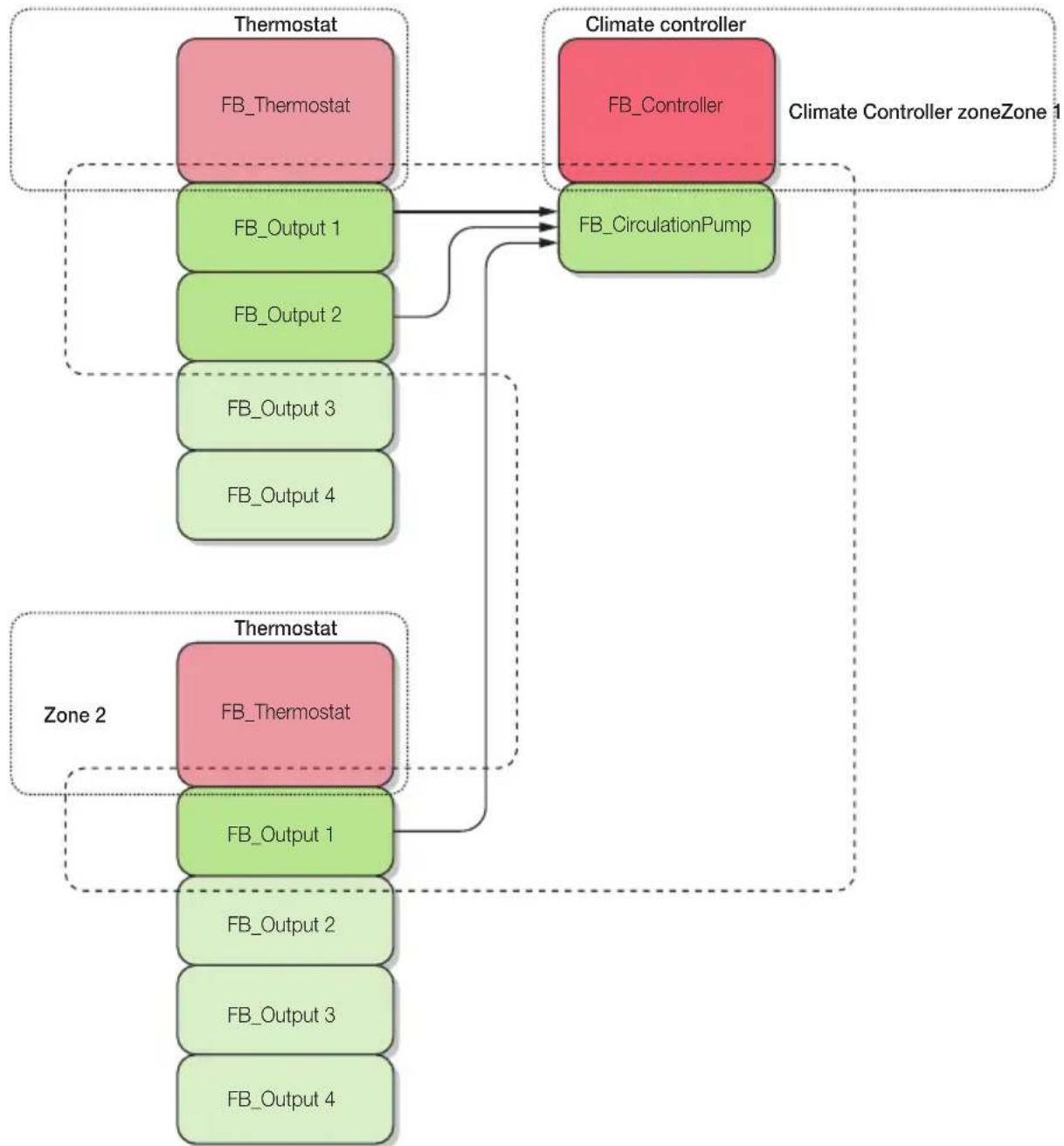
flowchart
graph TD
    subgraph Thermostat
        A["FB_Thermostat"] --> B["FB_Output 1"]
        B --> C["FB_Output 2"]
        C --> D["FB_Output 3"]
        D --> E["FB_Output 4"]
    end

    subgraph Climate Controller
        F["FB_Controller"] --> G["FB_CirculationPump"]
    end

    subgraph Zone 2
        H["FB_Thermostat"] --> I["FB_Output 1"]
        I --> J["FB_Output 2"]
        J --> K["FB_Output 3"]
        K --> L["FB_Output 4"]
    end

    A -.-> F
    B -.-> H
    C -.-> H
    D -.-> H
    E -.-> H
    G -.-> H
    I -.-> H
It will be therefore necessary to enter the desired group and add the climate controller pressing the configuration button once; then the control unit automatically enlists the Circulation pump functional unit.
N.B. This procedure is effective provided that at least the main functional unit has already been previously configured.
Configuration on the controller
Configuring the External Temperature functional unit
This functional unit can be used when one of the two modes, Heating or Air-conditioning, is set as Modulating. The unit can be configured:
- integrating it in a group where there is the NTC functional unit of a 3 input device 01467 (the climate controller will receive the temperature value from the By-me bus as shown in the following figure);
- in a group dedicated to it (the climate controller will send on the By-me bus the temperature read by T1);
- in the same group of the Main functional unit (in this case it will provide only the external temperature value to be displayed in a touch screen, etc.).

flowchart
graph TD
    A["Thermostat FB_Thermostat"] --> B["FB_Output 1"]
    A --> C["FB_Output 2"]
    A --> D["FB_Output 3"]
    A --> E["FB_Output 4"]
    F["Climate controller FB_Controller"] --> G["FB_CirculationPump"]
    F --> H["FB_ExternalTemp"]
    G --> I["3 inputs"]
    H --> J["FB_NTC"]
    K["Thermostat FB_Thermostat"] --> L["FB_Output 1"]
    K --> M["FB_Output 2"]
    K --> N["FB_Output 3"]
    K --> O["FB_Output 4"]
    I -.-> G
    J -.-> G
    K -.-> H
It will be therefore necessary to enter the desired group and add the climate controller pressing the configuration button once; the control unit automatically enlists the External Temperature functional unit.
Configuration on the controller
N.B.: When an External Temperature functional unit is configured in a dedicated group and this unit is the first to be configured (i.e., the group was empty), the controller (which has the probe physically connected at its terminals) is able to provide the external temperature to other regulators 01465; to do this, just set up later in the same group all the External Temperature units of the other regulators and they will use the measurement. The configuration in empty groups of a climate controller that has the Main functional unit configured but the External Temperature and Auxiliary Temperature functional units that are not, activates the request in the control unit whether to configure or not these units; if the operator chooses to continue, the configuration proceeds automatically without displaying additional requests.
Configuring the Auxiliary Temperature functional unit (T3)
The Auxiliary Temperature unit can be configured:
- in a dedicated group (empty group) to simply provide a temperature value to be displayed (for example in a touch screen);
- within the group where there is the main functional unit and therefore the T3 input is used as Shut-down alarm input (for notification of a shut-down alarm of the climate controller). See the following figure:

flowchart
graph TD
    A["Thermostat"] --> B["FB_Thermostat"]
    A --> C["FB_Output 1"]
    A --> D["FB_Output 2"]
    A --> E["FB_Output 3"]
    A --> F["FB_Output 4"]
    G["Climate controller"] --> H["FB_Controller"]
    G --> I["FB_CirculationPump"]
    G --> J["FB_ExternalTemp"]
    G --> K["FB_AuxiliaryTemp"]
    L["3 inputs"] --> M["FB_NTC"]
    L --> N["Thermostat"]
    L --> O["FB_Thermostat"]
    P["Thermostat"] --> Q["FB_Thermostat"]
    P --> R["FB_Output 1"]
    P --> S["FB_Output 2"]
    P --> T["FB_Output 3"]
    P --> U["FB_Output 4"]
    style A fill:#f9f,stroke:#333
    style G fill:#f9f,stroke:#333
    style L fill:#ccf,stroke:#333
Configuration on the controller
To add the Auxiliary Temperature functional unit of the climate controller to the desired group, simply press the configuration button once.
N.B.: The configuration in empty groups of a climate controller that has the Main functional unit configured but the External Temperature and Auxiliary Temperature functional units that are not, activates the request in the control unit whether to configure or not these units; if the operator chooses to continue, the configuration proceeds automatically without displaying additional requests.
Configuring the Humidity functional unit
This functional unit is used when it is required to use the anti-condensation function of the regulator in the case of air conditioning system. The unit must be configured in a group in which there is the general Analogue input function block of a 3 input device 01467 previously set as Humidity sensor xx433.
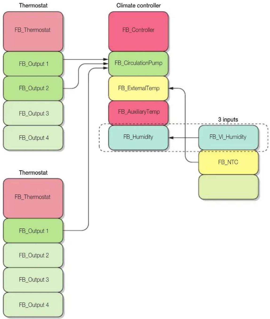
flowchart
graph TD
    A["Thermostat"] --> B["FB_Thermostat"]
    A --> C["FB_Output 1"]
    A --> D["FB_Output 2"]
    A --> E["FB_Output 3"]
    A --> F["FB_Output 4"]

    G["Climate controller"] --> H["FB_Controller"]
    G --> I["FB_CirculationPump"]
    G --> J["FB_ExternalTemp"]
    G --> K["FB_AuxiliaryTemp"]
    G --> L["FB_Humidity"]

    M["Thermostat"] --> N["FB_Thermostat"]
    M --> O["FB_Output 1"]
    M --> P["FB_Output 2"]
    M --> Q["FB_Output 3"]
    M --> R["FB_Output 4"]

    S["3 inputs"] --> T["FB_VI_Humidity"]
    S --> U["FB_NTC"]
Configuration on the controller
The anti-condensation function intervenes only in the air conditioning controller mode and it limits the value of the delivery temperature so that condensation does not develop in the environment; the calculation of the delivery temperature limit varies depending on the work mode:
- modulating work mode: the temperature limit is determined according to the desired temperature and the percentage of humidity detected.
- fixed work mode: the temperature limit is determined only as a function of the percentage of humidity detected as shown in the following table.
| Humidity [%] | < 30 35 40 45 | 50 55 60 65 70 | 75 80 85 90 95 | 99 >100 | ||||||||||
| Temperature [°C] | 10 (minimum programmable SetPoint) | 11,2 18,2 15,1 | 6,8 18,3 | 19,7 21,1 | 22,2 23,3 | 24,3 25, | 26,2 27, | 1 27,8 28,0 |
IMPORTANT: This function can not guarantee that no condensation forms in systems with underfloor or radiant panels cooling if they are subjected to sudden temperature changes (e.g. prolonged opening of a window, or starting the air conditioning in the presence of high ambient temperature and humidity); the high thermal inertia of such systems in fact, does not allow in any case to avoid condensation if not accompanied by an adequate dehumidification system.
Note on automatic programmes:
The temperature values that are assigned by default to the automatic programmes are: T1-heating = 15°C, T2-heating = 18°C, T3-heating = 20°C, T1-air conditioning = 26°C, T2-air conditioning = 28°C, T3-air conditioning = 30°C.
If in case of fixed work mode these values are obviously conservative and the installer will set them to the values appropriate to the delivery setpoint temperature.
3.1.2 Configuration of proportional analogue 4-output actuator 01466
Configuration of a temperature control application
After pressing the device configuration button, the controller views the options defining the type:
Select output type → Select "Voltage" or "Current" → Select characteristic → Select control polarity "Normal" or "Inverted" → Select range → Select range in V or in mA or "Custom" depending on the type → Select min or max
Confirm→ Yes
Configuration of an automation application
Important: First configure the proportional output device and then the actuator and the By-me control.
Select use "Button control" or "Extension" → Select "Voltage or Current" → Select characteristic → Select control polarity "Normal" or "Inverted" → Select range → Select range in V or mA or "Custom" depending on the type → Select min or max
Confirm Yes
- The Automation application "Button control" is used to control the proportional output from a By-me button.
- The Automation application "Extension" is used, with art.01466, to send information read by the analogue input (art.01467) to the bus and transduce it remotely via the proportional actuator, thus assuring the extension function.
Configuration on the controller
3.1.3 Configuration of device with 3 analogue signal inputs 01467
The device consists of 3 functional units, i.e.:
-
Generic analogue input -V -A .
-
NTC (thermometer for NTC probe) 🔊.
-
Brightness adjuster (must be configured in a group with a universal dimmer and relative buttons)
N.B.: The universal dimmers must be configured as White (item 20549-19549-14549 or 20137-19137-14137 + 20529-19529-14529).
After configuring the dimmer to set the control set point, proceed as follows:
- set the brightness controller;
- set the dimmer controller;
- make an adjustment and wait a minute; following the ambient light change the controller should change its output.
During configuration, to select the desired unit, press the configuration button several times until the corresponding LED comes on.
Important:
- If it is required to configure the system consisting of a 3 input device 01467 (using the functional unit 1 as an On/Off control), by any actuator device and by a rocker device it is necessary to first configure the 3 input device, then the actuator to associate to it and finally the rocker switch.
In case the actuator is configured first, then the 3 input device 01467 and then the rocker switch, the control unit will not properly create the relevant group.
- If it is required to configure the system consisting of a 3 input device 01467 (using the functional unit 3), by a universal dimmer device and by a rocker device it is necessary to first configure the 3 input device, then the universal dimmer and finally the rocker switch.
Also in this case, if the devices sequence of configuration is reversed, the control unit will not properly create the relevant group.
Example:
If the functional unit to configure is the Generic analogue input after pressing the device configuration button the controller views the options defining the type:
Select sensor → Select "Humidity xx433" or "Generic" → Select use → Select "Generic Use", "On/Off control" or "Extension" → Select input type → Select "Voltage" or "Current" → Select range → Select range in V or in mA depending on the type → Select variable → Select the variable from those proposed → Select range → Select min or max
Confirm Yes
N.B.:
- By selecting Humidity xx433 you can only connect the humidity sensor Vimar 20433-19433-14433.
- By selecting Generic you can connect any other voltage or current sensor.
- Select Generic Use only to read the input values.
Configuration on the controller
3.1.4 Configuration of thermostat 02951
The thermostat consists of 1 Main functional unit and 4 identical Output functional units that are configured in the groups in which we wish to include also the actuator to control the climate control source (radiators, fan-coils, etc.).
To enter the thermostat configuration mode you must:
- Press the areas at the top and at the bottom on the left-hand side of the display at the same time, as shown in the following figure:
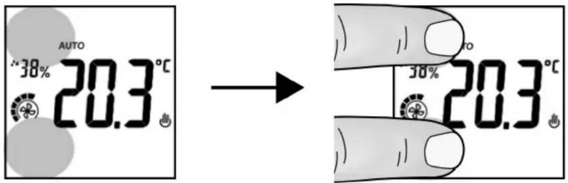
The backlighting turns red and the display shows CnF (configuration).
- When first pressing the areas illustrated above the Main functional unit is configured
- When pressed again (without resetting the device) the other Output functional units are configured, one for each press of the button.
WARNING: The Output functional can be removed individually while removing the Main functional unit also removes all the other currently configured Output functional units.
3.1.5 Configuration of temperature probe 20538-19538-14538
The temperature probe consists of 1 Main functional unit and 4 identical Output functional units that are configured in the groups in which we wish to include also the actuator to control the climate control source (radiators, fan-coils, etc.).
When the controller asks you to press the device button:
- When first pressing the probe configuration button the Main functional unit is configured.
- When pressed again (without resetting the device) the other Output functional units are configured, one for each press of the button.
WARNING: The Output functional can be removed individually while removing the Main functional unit also removes all the other currently configured Output functional units.
Configuration on the controller
3.1.6 Configuration of IR interface 20584.1-19584.1-14584.1
The device consists of 2 identical functional units.
During configuration, when pressing the device button, it is automatically associated to the functional unit that is still free. For example, the 2 units can be associated respectively to a heating output functional unit and a thermostat cooling output unit.
The device can be configured in the Climate menu only if in the group a thermostat Output functional unit has already been configured.
The IR interface can be controlled from a button or from the device with 3 analogue signal inputs (art. 01467). If there is a 3-input device 01467 and a button, the latter will be associated to the 3-input device 01467 (to enable or disable the exceeding threshold function).
The IR interface is able to save the button of an infrared remote control and repeat its operation after a By-me command. When the interface is active the LED, if enabled on the control unit, is lit steady on green; it flashes briefly each time a By-me command is received that involves sending IR commands.
It is possible to acquire up to 12 actions (action = repetition of an infrared remote control button) that, in the control unit menu, are named as follows:
Action 1 (A1)
Action 2 (A2)
Action 3 (A3)
Action 4 (A4)
Action 5 (A5)
Action 6 (A6)
Action 7 (A7)
Action 8 (A8)
Action 9 (A9)
Action 10 (A10)
Action 11 (A11)
Action 12 (A12)
Operation is ensured when, starting with the actions, the following commands thus named on the control unit are coded:
Command Meaning
| IR ON ON control |
| IR OFF OFF control |
| IR V1 Speed 1 control |
| IR V2 Speed 2 control |
| IR V3 Speed 3 control |
Each command can be coded as the sequence of 1, 2, 3 or 4 actions and this corresponds to consecutively pressing up to 4 buttons on the remote control of the controlled device.
Configuration
The IR interface 20584.1-19584.1-14584.1 is configured on the control unit in two phases:
- Record button of a remote control (action)
- Pair actions with the actual command.
Configuration on the controller
Creation of an action and recording the key of a remote control
Setup → Configuration → Groups → HVAC groups → Select the group in which the IR interface has been inserted → Paired devices → Select the IR interface → Device parameters → With Action Management → Add
Set the index of the action and select Next → Acquire action; the LED will blink.
Press the configuration button of the interface 20584.1-19584.1-14584.1; the LED will be lit steady.
Move the remote control near to the IR interface (to a distance of about 10 cm) and, within 10 s, as in normal use, press the button you want to record.
Lastly, select Add to continue or Back and tap Save.
If acquisition is successful, the interface LED will go out; the action will then be displayed on the control unit in the list of configured actions (A1, A2, etc.).
If the acquisition is not successful (blinking fast) carry out the following check:
- position the remote control towards the window of the IR interface at a distance of about 10 cm;
- check the condition of the batteries of the remote control and its operation;
- check that the infrared frequency of the audio device is between 30kHz and 60kHz.
As regards the remote control, you should save the buttons that are generally used for ON, OFF, V1, V2 and V3 operations and in the table below note down the reference between the name of the memory used and the corresponding remote control button.
Action Remote control button
| Action 1 |
| Action 2 |
| Action 3 |
| Action 4 |
| Action 5 |
| Action 6 |
| Action 7 |
| Action 8 |
| Action 9 |
| Action 10 |
| Action 11 |
| Action 12 |
Modifying an action
Setup → Configuration → Groups → HVAC groups → Select the group in which the IR interface has been inserted → Paired devices → Select the IR interface → Device parameters → Acquired actions → Select the action to modify
Configuration on the controller
The available options are the following:
• Acquire action
- Press the interface configuration button and then the remote control button to be paired.
- Remove action
- Proceed to remove the action? → Yes.
The selected action is deleted and the control unit confirms the operation has concluded.
Pair actions with the actual command.
This menu is used to create the commands pairing up to 4 already recorded actions.
Setup → Configuration → Groups → HVAC groups → Select the group in which the IR interface has been inserted → Paired devices → Select the IR interface → Device parameters → Pair commands
Select the command to pair (ON, OFF, etc.); 4 selection fields (Action 1, Action 2, Action 3 and Action 4) are then displayed, each one of which represents an action paired with the command.
The 4 fields will show dashes if there is no paired action.
It is now possible in each field to choose any of the recorded actions; the fields are indexed from 1 to 4 that is the order in which the actions will be performed by the command.
Lastly touch Set that causes the data to be transferred to the IR device.
Example.
| Action Remote control button |
| Action 1 On |
| Action 2 OFF |
| Action 3 - |
| Action 4 - |
| Action 5 - |
| Action 6 Speed 2 |
| Action 7 - |
| Action 8 - |
| Action 9 - |
| Action 10 - |
| Action 11 - |
| Action 12 - |
Configuration on the controller
| Command Action 1 Action 2 Action 3 Action 4 |
| ON Action 1 Action 6 None None |
| OFF Action 2 None None None |
| V1 None None None None |
| V2 None None None None |
| V3 None None None None |
In the example above note that the ON command is coded as the playback sequence of Actions 1 and 6 that correspond to pressing the On and Speed 2 buttons of a hypothetical original remote control in sequence. The ON operation is then paired with the actions of the 2 buttons indicated alternated by the Inter-time parameter that causes switching on the device and selecting the speed as required for the ON command.
3.2 Setting/changing the parameters.
Device parameters can be set and/or modified in order to customize operation to adapt the system to the various installation requirements.
Setup → Configuration → Groups → Climate → Select the group by scrolling through the list → Associated devices → Select the functional unit by scrolling through the list → Device parameters
• CLIMATE CONTROLLER FOR HEATING SYSTEMS 01465
Main functional unit and Circulation pump
■ Max. delivery temp.: Parameter for setting the maximum delivery temperature in heating.
It can also be used as a threshold for limiting the screed temperature when the delivery supplies an underfloor heating system; the screed temperature measured through the auxiliary probe is not used since, because of the thermal dispersion, it will be less than the delivery temperature.
■ Min. delivery temp.: Parameter for setting the maximum delivery temperature in air-conditioning.
■ Minimum voltage/current adjustment value on the proportional output:
- Minimum adjustment in current 0.0 mA.
- Minimum adjustment in voltage 0.0 V.
■ Maximum voltage/current adjustment value on the proportional output:
- Maximum adjustment in current 20.4 mA.
- Maximum adjustment in voltage 10.2 V.
■ Control polarity: Is the direction in which the proportional output control is made.
- Select "Normal" and, as the % value increases, the valve opening will increase.
For example: 0%=Closed, 100%=Open
- Select "Inverted" and, as the % value increases, the valve opening will decrease.
For example: 0%=Open, 100%=Closed"
■ Valve in OFF position: Parameter that, if the circulation pump will be turned off, is used to set whether the mixing valve has to be closed (0%) or placed in a desired position (1..100%); in any case, the control algorithm is interrupted.
Configuration on the controller
The climate controller, after an outputs inactivity time equal to 12h, starting from 2h later makes a switching sequence to prevent the seizure of the connected load (either pump or valve); more precisely uses the following three parameters:
- Pump anti-seize: Pump switching On/Off for a fixed time; this time value affects the PID algorithm whether the valve is ON/OFF or proportional.
- Open/Close valve anti-seize: Open/off switching for a fixed time.
- Proportional valve anti-seize: 0-100% switching for a fixed time.
■ Valve opening time: It is the time taken for the valve to perform a closing/opening cycle (On/Off). It is used for the calibration of the open/close valve.
■ Valve closing time: It is the time taken for the valve to perform an opening/closing cycle (On/Off). It is used for the calibration of the open/close valve.
■ Delivery probe type: It allows the operator to set the type of delivery probe installed in the system.
■ Value transmission: Indicates how to force the transmission of a temperature message.
■ Transmission interval: If the Transmission value is set on time-based the parameter indicates how often to send the measured value. If the Transmission value is set on time-based change the parameter indicates the minimum time to validated the change and activate the transmission.
■ Air-conditioning correction factor: K coefficient (fixed) for the calculation of the delivery temperature in Air-conditioning mode.
The coefficient is used to obtain the delivery temperature value through the relation:
T delivery = Setpoint + K x (Setpoint - T external)
Example of floor or fan-coil system
For an ambient temperature of 23^ C with external limit temperature of 35^ C; to obtain a delivery temperature of 14^ C, the air conditioning correction factor (K) must be equal to 0.8.
■ Heating correction factor: K coefficient (fixed) for the calculation of the delivery temperature in Heating mode.
The coefficient is used in the following formula to obtain the delivery temperature value:
T delivery = Setpoint + K x (Setpoint - T external)
Example of underfloor heating
For an ambient temperature of 20^ C with external limit temperature of 0^ C; to obtain a delivery temperature of 35^ C, the heating correction factor (K) must be equal to 0.8.
Example of a system with radiators or fan-coil
For an ambient temperature of 20^ C with external limit temperature of 0^ C; to obtain a delivery temperature of 60^ C, the heating correction factor (K) must be equal to 2.0.
■ Band (P): Parameter used by the PID algorithm to calculate the coeff. Kp = 100/Bp.
Corresponds to the breadth of proportional adjustment range: starting from the set temperature, this value the temperature range in which the system power goes from 0% to 100%.
For example: with the temperature, set to 50.0°C and Band (P) =4.0°C, the climate controller opens the valve at 100% when the delivery T. is <= 46.0 °C; as this temperature increases, the valve opening is consequently lowered down to 0% when the delivery temperature reaches 50°C. The value must be set consistently with the thermal capacity of the source to be controlled; in general, it is recommended to use small values for high thermal capacity (therefore longer reaction time) and vice versa.
■ Time (I): Parameter used by the PID algorithm to calculate the coeff. Ki = Kp/Ti.
Corresponds to the time passed which, when equal to the deviation from the setpoint (error), the additional
Configuration on the controller
component generates a contribution equal to that generated by the proportional component. The integral contribution is used to reduce the error on full operation if thermal energy is lost in the room controlled, as this contribution increases according to the time during which the setpoint is not reached. If this value is not set perfectly, it can cause transients with oscillations around the setpoint or it may take longer to reach the setpoint.
■ Time (D): Parameter used by the PID algorithm to calculate the coeff. Kd = Kp * Td.
Corresponds to the time only the proportional action would take to generate a command signal equal to that produced by the derivative action. The derivative contribution opposes the system variations and has no role in eliminating the error but is used to stabilise the control operations, particularly in systems that are characterized by sudden variations. The derivative contribution must be enabled with care, particularly in systems with long dead times, as this could make the control chain unstable; generally the most appropriate algorithm in these cases corresponds to type PI (proportional-integral).
N.B.:
1) The delivery temperature sending is automatic and takes place at every change of 0.1°C.
2) The execution time of the PID algorithm is derived from the minimum value of the two "Valve opening time" and "Valve closing time" parameters and is valid for both the open/close valve and the proportional valve.
External Temperature and Auxiliary Temperature
■ Probe type: It allows the operator to set the type of temperature probe installed in the system
■ Value transmission: Indicates how to force the transmission of a temperature message.
■ Transmission interval: If the Transmission value is set on time-based the parameter indicates how often to send the measured value. If the Transmission value is set on time-based change the parameter indicates the minimum time to validated the change and activate the transmission.
Humidity Functional unit
■ Probe calibration: It is the humidity measurement calibration value; this value is added to or subtracted from humidity measured by the sensor of the same group to obtain the desired value.
Types of alarm and climate controller actions
■ Delivery probe failure alarm: The controller shuts down (the pump is turned off and the mixing valve closed), the green status led flashes and the alarm is indicated by the bus.
■ External probe failure alarm: The climate controller forces the temperature measured at 30^ C in air conditioning and 0^ C in heating, the green status led flashes and the alarm is indicated by the bus.
■ Auxiliary probe failure alarm: In this case, the green device status led flashes and the alarm is indicated by the bus. The control does not shut down.
■ OUT3 proportional output overload alarm: In this case the proportional output is forced to 0 V/mA, the output (OUT3) green status led flashes and the alarm is indicated by the bus; there is no user adjustment lock. Once solved the cause that generated the alarm (for example an overcurrent), the output is automatically restored.
■ Shutdown alarm: The auxiliary contact input is opened or closed depending on the polarity set (NO or NC). If an alarm occurs the climate controller shutdown is started and therefore the pump turns off and the valve closes; once the alarm has been resolved, the controller resumes normal operation.
Configuration on the controller
• ACTUATOR WITH 4 PROPORTIONAL ANALOGUE OUTPUTS 01466
■ Control polarity: Represents the direction of the output analogue signal with which the valve is controlled (available only for temperature control applications).
Select "Normal" and, as the % value increases, the valve opening will increase.
For example: 0%=Closed, 100%=Open
Select "Inverted" and, as the % value increases, the valve opening will decrease.
For example: 0%=Open, 100%=Closed
■ Minimum value: Minimum value of voltage/current adjustment on the output channel:
- Minimum adjustment in current 0.0 mA.
- Minimum adjustment in voltage 0.0 V.
■ Maximum value: Maximum value of voltage/current adjustment on the output channel:
- Maximum adjustment in current 20.4 mA.
- Maximum adjustment in voltage 10.2 V.
■ Adjustment speed: Adjustment speed of the device analogue output.
Available only for Automation applications with "Button control", used to set the adjustment speed i.e. the variation speed of the analogue output signal.
■ OFF value: Output value in Off state.
Available only for Automation applications with "Button control", the parameter specifies the value in V-mA that the output channel must have when it receives an OFF command.
The following values can be set:
- if OFF, the output goes to the "minimum value".
- if OFF, the output goes to the zero value.
Example: If the control is used with a button with a dimmer function, it is possible to choose which value the proportional output assumes when the actuator receives an Off command.
• DEVICE WITH 3 ANALOGUE SIGNAL INPUTS 01467
The device consists of 3 functional units to which the respective parameters are associated.
Functional unit input 0-10 V or 4-20 mA
■ Control threshold: The parameter is used to modify the setpoint value.
■ Hysteresis: The parameter is used to modify the hysteresis value.
■ Minimum value: Minimum value of the input signal (example: in a 1-10 V sensor the associated value when the input read is equal to 1 V.
■ Maximum value: Maximum value of the input signal (example: in a 1-10 V sensor the associated value when the input read is equal to 10 V).
■ Enabling on start-up: Defines the behaviour of the control on start-up:
- command enabled;
- command disabled;
- analogue control at the last variation before switching off.
■ Control polarity: Used to invert the output control behaviour.
■ By selecting Value transmission you can set the following parameters:
→ Value transmission: Indicates how to force the transmission of a message.
▶ Transmission threshold: Indicates the difference between 2 values read to generate a message transmission.
Configuration on the controller
- Transmission interval: Indicates the time difference between 2 values read to generate the transmission of a message.
- Selecting Percentage transmission, which has operates only in case of a device configured as “Extension”, it is possible to set the following parameters:
→ Value transmission: Indicates how to force the transmission of a scalar message.
Transmission threshold: Indicates the difference between 2 values read to generate a scalar message transmission.
- Transmission interval: Indicates the time difference between 2 values read to generate the transmission of a scalar message.
N.B.
The Value Transmission and Percentage Transmission parameters both transmit the value measured by the sensor; the former is the actual measurement expressed with 2 bytes while the latter is the percentage measurement of the value between MIN and MAX expressed with 1 byte.
Example 1: If you set min = 0 and max = 10000mV with the sensor that measures 5V at the output you will have a transmission value of 5000mV or a transmission percentage of 50%.
Example 2: If you set min = 0 and max = 10000mV with the sensor that measures 10V at the output you will have a transmission value of 10000mV or a transmission percentage of 100%
Functional unit input for NTC temperature sensor
■ Value transmission: Indicates how to force the transmission of a temperature message.
■ Transmission threshold: Indicates the difference between 2 values read to generate a temperature message transmission.
■ Transmission interval: Indicates the time difference between 2 values read to generate a temperature message transmission.
Functional unit input for brightness adjustment sensor
■ Hysteresis: The parameter is used to modify the adjustment hysteresis value.
• THERMOSTAT 02951
The thermostat consists of 2 functional units to which the respective parameters are associated.
Functional unit thermostat
■ Screed threshold: Temperature value above which the screed limitation cuts in.
When this limitation is in effect, the thermostat will close its valve if the temperature measured by the Probe 2 (underfloor heating screed) exceeds the set threshold.
Caution: This is an extra action (and not for safety) that is added to the protection performed by the thermostatic valve prescribed by system regulations.
■ Probe 2: Sets the use of probe 2; the following values can be set:
- Not present = Probe 2 not present.
- Temp. Control. (exclusive) = for temperature control, in place of Probe 1.
- Temp. Control. (combined) = per la temperature control, used as a medium with Probe 1 (large rooms).
- Screen Limit. = for screed limitation.
- View = view only (e.g: temperature in another room).
Configuration on the controller
■ Neutral zone range: Sets the range of the Neutral Zone centred on the relative setpoint
In the Neutral Zone adjustment mode, the thermostat automatically switches between heating and cooling according to the set set-point, the temperature measured and considering any neutral zone around the set point defined by the Neutral Zone Range parameter (set from 1°C to 5°C in 1°C steps).
For example, if the set point is set to 20^ C and the neutral zone range is 2^ C, the thermostat will switch the heating on if the temperature falls below 19^ C (set point – neutral zone range/2) and will switch on the air conditioning if the temperature rises above 21^ C (set point + neutral zone range/2). In this way a band of 2^ C around which the thermostat neither heats or cools is defined (thus the name neutral zone).
Important:
-The "neutral zone" adjustment can of course be used only on 4-pipe systems (which can both heat and cool at the same time).
- In the neutral zone adjustment mode, the thermostat only allows Manual and OFF operating modes.
■ Operating limitations: Defines the operating mode limitation, the following values can be set:
Both setpoint operating or adjustment limitations are useful in applications such as guest rooms, offices, shops and tertiary applications generally.
■ Setpoint adj. limit.: Defines the setpoint adjustment range limitation, the following values can be set:
- No limitation = the setpoint can be adjusted across all the available range.
- Range 0 = the current setpoint can be modified by maximum +/- 0.5°C of the setpoint value saved in the memory.
- Range 1 = as above but +/- 1°C.
- Range 2 = as above but +/- 2°C.
- Range 3 = as above but +/- 3°C.
- Range 4 = as above but +/- 4°C.
- Range 5 = as above but +/- 5°C.
■ View: Defines what to view in the main screen; the following values can be set:
- Room temp. = room temperature (normal)
- Current setpoint = set point temperature
- Current setpoint delta.
By selecting "current setpoint delta":
- in the event of active setpoint adjustment limitations, the display shows the current setpoint delta compared to that locked in the limitation.
Example: Setpoint adj. limit.→ Range 2, the display will show the values from -2°C to +2°C
- if there are no setpoint adjustment limitations, the display shows the setpoint value.
The "current setpoint delta" displayed is therefore used mainly in combination with Setpoint adj. limit..
■ Humidity view: Defines the viewing of the humidity value in the thermostat display.
Important: To obtain this view, you must configure the functional unit input 0-10 V of device 01467 connected to the humidity probe in the same group as the thermostat.
■ Probe 1 calibration: Static calibration value of the internal probe (probe 1). In fact this is an offset to which the temperature value read by the probe must be summed.
Configuration on the controller
■ Probe 2 calibration: Static calibration value of the external probe (probe 2). In fact this is an offset to which the temperature value read by the probe must be summed.
■ By selecting Temperature trans. you can set the following parameters:
→ Value transmission: Indicates how to force the transmission of a temperature message.
Transmission interval: Indicates the time difference between 2 values read to generate a temperature message transmission.
Use Temperature trans. to set the period of updating the temperature value on the supervisor devices (touch screens, etc.).
■ By selecting Window you can set the following parameters:
Reaction time: Sets the reaction time if a window warning is received; in fact, it indicates after how much time the thermostat block should come on if a window is open.
Example:
When the window is closed the heating/conditioning is on; if the window is opened the heating/conditioning stays on for the time set in the Reaction time. If within that time interval the window is closed, the heating/conditioning remains on.
→ Reactivation time: Sets the reactivation time if a window warning is received; in fact, it indicates after how much time the thermostat block should be switched off due to a window being open.
Example:
When the window is closed the heating/conditioning is on; if the window is opened the heating/conditioning is switched off and stays on for the time set in the Reactivation time. At the end of the time interval the heating/conditioning comes back on whether or not the window has been closed.
Functional unit output
■ Control alg.: Select the algorithm to use for the temperature control of the relative output.
On/Off: This is the traditional "threshold" control so that, on exceeding the set temperature increased by the temperature differential (vice versa for air-conditioning), the heating is switched off to then be turned back on when the room temperature drops below the set temperature.
PID: This is an evolved algorithm that is able to keep the temperature in the environment more stable, increasing comfort; this algorithm switches the system on and off appropriately so there will be a gradual increase or decrease in the thermal (or refrigerating) power of the system itself. To fully exploit the performances, it must be appropriately calibrated according to the type of environment or heating system, by setting the relative parameters.
■ Temperature differential: Sets the hysteresis value to be used in the case of an on/off algorithm (can be set from 0.1°C to 1°C in 0.1°C steps)
■ PWM time: Sets the length of a PWM cycle in the case of a PID algorithm for controlling on/off valves.
It therefore corresponds to the time in which a cycle of regulation is completed; the shorter this time, the better the regulation but the temperature control system is under greater stress.
This parameter setting is thus the result of a compromise between the accuracy of the regulator and the load on the system; in general, the rule is that Tb can be that much higher (and therefore put fewer demands on the system), the slower the system or the larger the environment to regulate.
Important: The value must be much greater than the on and off times of the valves
■ Band (P): Parameter used by the PID algorithm to calculate the coeff. Kp = 100/Bp.
Corresponds to the breadth of proportional adjustment range: starting from the set temperature, this value the temperature range in which the system power goes from 0% to 100%.
Configuration on the controller
For example: with the (heating) temperature, set to 20.0°C and Band (P) =4.0°C, the thermostat runs the heating system at 100% when T.ambient is <= 16.0 °C; as this temperature increases, the system power is consequently lowered down to 0% when the ambient temperature reaches 20°C. The value of Tb must be set consistently with the thermal capacity of the room controlled; in general, it is recommended to use small values for rooms with a good level of thermal insulation and vice versa.
■ Time (I): Parameter used by the PID algorithm to calculate the coeff. Ki = Kp/Ti.
Corresponds to the time passed which, when equal to the deviation from the setpoint (error), the additional component generates a contribution equal to that generated by the proportional component. The integral contribution is used to reduce the error on full operation if thermal energy is lost in the room controlled, as this contribution increases according to the time during which the setpoint is not reached. If this value is not set perfectly, it can cause transients with oscillations around the setpoint or it may take longer to reach the setpoint.
■ Time (D): Parameter used by the PID algorithm to calculate the coeff. Kd = Kp * Td.
Corresponds to the time only the proportional action would take to generate a command signal equal to that produced by the derivative action. The derivative contribution opposes the system variations and has no role in eliminating the error but is used to stabilise the control operations, particularly in systems that are characterized by sudden variations. The derivative contribution must be enabled with care, particularly in systems with long dead times, as this could make the control chain unstable; generally the most appropriate algorithm in these cases corresponds to type PI (proportional-integral).
■ By selecting Fan-coil you can set the following parameters:
→ Speed control: It is possible to select two different control modes:
- Interlock: the thermostat sends a control message exclusively at a single speed: V1, V2 or V3
- Step-step: the thermostat sends a message cumulatively: V1, V1+V2, V1+V2+V3
→ Switch-on delay: It sets the delay time of the fan start.
This parameter is used only during the operating or adjustment mode change while it is not used during temperature control (for example if the thermostat switches off the output and then switches it back on)
→ Speed band: It defines the thermal delta to run the fancoil fan at maximum speed.
The speed scale (in the case of an on/off algorithm) is defined in correspondence to the difference between the ambient temperature and the current Setpoint.
In addition to those described above, using the menu:
Climate → Setup → Zone settings → Select the zone to associate the thermostat to
it is possible to set the following parameters:
■ Aux. heat threshold: Difference from the setpoint for starting the boost function in heating mode; the function is switched off when the required temperature (setpoint) is reached, increased by the temperature differential.
■ Aux. cond. threshold: Difference from the setpoint for starting the boost function in aircon mode; the function is switched off when the required temperature (setpoint) is reached, decreased the temperature differential.
■ Ecometer: Enables the ecometer function. If the ecometer is disabled, the backlighting is fixed and turns to the colour set in the Backlight Colour parameter; otherwise the backlighting varies according to the set setpoint
■ Backlight colour: Sets the backlighting RGB colour coordinates
■ Temperature unit: Sets the unit of measure used to view the temperature on the display
Configuration on the controller
■ Keypad lock: Enables the keypad lock (disables the keys).
■ Sound: Enabling of sounds associated to buttons when pressed.
• TEMPERATURE PROBE 20538-19538-14538
The temperature probe consists of 2 functional units to which the respective parameters are associated.
Functional unit thermostat
■ Screed threshold: Temperature value above which the screed limitation cuts in.
When this limitation is in effect, the thermostat will close its valve if the temperature measured by the Probe 2 (underfloor heating screed) exceeds the set threshold.
Caution: This is an extra action (and not for safety) that is added to the protection performed by the thermostatic valve prescribed by system regulations.
■ Probe 2: Sets the use of probe 2; the following values can be set:
- Not present = Probe 2 not present.
- Temp. Control. (exclusive) = for temperature control, in place of Probe 1.
- Temp. Control. (combined) = per la temperature control, used as a medium with Probe 1 (large rooms).
- Screen Limit. = for screed limitation.
- View = view only (e.g: temperature in another room).
■ Neutral zone range: Sets the range of the Neutral Zone centred on the relative setpoint
In the Neutral Zone adjustment mode, the thermostat automatically switches between heating and cooling according to the set set-point, the temperature measured and considering any neutral zone around the set point defined by the Neutral Zone Range parameter (set from 1°C to 5°C in 1°C steps).
For example, if the set point is set to 20^ C and the neutral zone range is 2^ C, the thermostat will switch the heating on if the temperature falls below 19^ C (set point – neutral zone range/2) and will switch on the air conditioning if the temperature rises above 21^ C (set point + neutral zone range/2). In this way a band of 2^ C around which the thermostat neither heats or cools is defined (thus the name neutral zone).
Important:
-The "neutral zone" adjustment can of course be used only on 4-pipe systems (which can both heat and cool at the same time).
- In the neutral zone adjustment mode, the thermostat only allows Manual and OFF operating modes.
■ Setpoint adj. limit.: Defines the setpoint adjustment range limitation, the following values can be set:
- No limitation = the setpoint can be adjusted across all the available range.
- Range 0 = the current setpoint can be modified by maximum +/- 0.5°C of the setpoint value saved in the memory.
- Range 1 = as above but +/- 1°C.
- Range 2 = as above but +/- 2°C.
- Range 3 = as above but +/- 3°C.
- Range 4 = as above but +/- 4°C.
- Range 5 = as above but +/- 5°C.
■ Probe 1 calibration: Static calibration value of the internal probe (probe 1). In fact this is an offset to which the temperature value read by the probe must be summed.
■ Probe 2 calibration: Static calibration value of the external probe (probe 2). In fact this is an offset to which the temperature value read by the probe must be summed.
Configuration on the controller
■ By selecting Temperature trans. you can set the following parameters:
→ Value transmission: Indicates how to force the transmission of a temperature message.
Transmission interval: Indicates the time difference between 2 values read to generate a temperature message transmission.
Use Temperature trans. to set the period of updating the temperature value on the supervisor devices (touch screens, etc.).
■ By selecting Window you can set the following parameters:
Reaction time: Sets the reaction time if a window warning is received; in fact, it indicates after how much time the thermostat block should come on if a window is open.
Example:
When the window is closed the heating/conditioning is on; if the window is opened the heating/conditioning stays on for the time set in the Reaction time. If within that time interval the window is closed, the heating/conditioning remains on.
→ Reactivation time: Sets the reactivation time if a window warning is received; in fact, it indicates after how much time the thermostat block should be switched off due to a window being open.
Example:
When the window is closed the heating/conditioning is on; if the window is opened the heating/conditioning is switched off and stays on for the time set in the Reactivation time. At the end of the time interval the heating/conditioning comes back on whether or not the window has been closed.
Functional unit output
■ Control alg.: Select the algorithm to use for the temperature control of the relative output.
On/Off: This is the traditional "threshold" control so that, on exceeding the set temperature increased by the temperature differential (vice versa for air-conditioning), the heating is switched off to then be turned back on when the room temperature drops below the set temperature.
PID: This is an evolved algorithm that is able to keep the temperature in the environment more stable, increasing comfort; this algorithm switches the system on and off appropriately so there will be a gradual increase or decrease in the thermal (or refrigerating) power of the system itself. To fully exploit the performances, it must be appropriately calibrated according to the type of environment or heating system, by setting the relative parameters.
■ Temperature differential: Sets the hysteresis value to be used in the case of an on/off algorithm (can be set from 0.1°C to 1°C in 0.1°C steps)
■ PWM time: Sets the length of a PWM cycle in the case of a PID algorithm for controlling on/off valves. It therefore corresponds to the time in which a cycle of regulation is completed; the shorter this time, the better the regulation but the temperature control system is under greater stress. This parameter setting is thus the result of a compromise between the accuracy of the regulator and the load on the system; in general, the rule is that Tb can be that much higher (and therefore put fewer demands on the system), the slower the system or the larger the environment to regulate.
Important: The value must be much greater than the on and off times of the valves
■ Band (P): Parameter used by the PID algorithm to calculate the coeff. Kp = 100/Bp.
Corresponds to the breadth of proportional adjustment range: starting from the set temperature, this value the temperature range in which the system power goes from 0% to 100%.
For example: with the (heating) temperature, set to 20.0°C and Band (P) =4.0°C, the thermostat runs the heating system at 100% when T.ambient is <= 16.0 °C; as this temperature increases, the system power
Configuration on the controller
is consequently lowered down to 0% when the ambient temperature reaches 20^ C. The value of Tb must be set consistently with the thermal capacity of the room controlled; in general, it is recommended to use small values for rooms with a good level of thermal insulation and vice versa.
■ Time (I): Parameter used by the PID algorithm to calculate the coeff. Ki = Kp/Ti.
Corresponds to the time passed which, when equal to the deviation from the setpoint (error), the additional component generates a contribution equal to that generated by the proportional component. The integral contribution is used to reduce the error on full operation if thermal energy is lost in the room controlled, as this contribution increases according to the time during which the setpoint is not reached. If this value is not set perfectly, it can cause transients with oscillations around the setpoint or it may take longer to reach the setpoint.
■ Time (D): Parameter used by the PID algorithm to calculate the coeff. Kd = Kp * Td.
Corresponds to the time only the proportional action would take to generate a command signal equal to that produced by the derivative action. The derivative contribution opposes the system variations and has no role in eliminating the error but is used to stabilise the control operations, particularly in systems that are characterized by sudden variations. The derivative contribution must be enabled with care, particularly in systems with long dead times, as this could make the control chain unstable; generally the most appropriate algorithm in these cases corresponds to type PI (proportional-integral).
■ By selecting Fan-coil you can set the following parameters:
→ Speed control: It is possible to select two different control modes:
- Interlock: the thermostat sends a control message exclusively at a single speed: V1, V2 or V3.
- Step-step: the thermostat sends a message cumulatively: V1, V1+V2, V1+V2+V3.
→ Switch-on delay: It sets the delay time of the fan start.
This parameter is used only during the operating or adjustment mode change while it is not used during temperature control (for example if the thermostat switches off the output and then switches it back on).
→ Speed band: It defines the thermal delta to run the fancoil fan at maximum speed.
The speed scale (in the case of an on/off algorithm) is defined in correspondence to the difference between the ambient temperature and the current Setpoint.
In addition to those described above, using the menu:
Climate → Setup → Zone settings → Select the zone to associate the thermostat to
it is possible to set the following parameters:
■ Aux. heat threshold: Difference from the setpoint for starting the boost function in heating mode; the function is switched off when the required temperature (setpoint) is reached, increased by the temperature differential.
■ Aux. cond. threshold: Difference from the setpoint for starting the boost function in aircon mode; the function is switched off when the required temperature (setpoint) is reached, decreased the temperature differential.
• IR INTERFACE 20584.1-19584.1-14584.1
On the control unit, on the screen for the parameters of the IR interface there are also:
■ LED control: (default 1= enabled). The LED signals IR transmission.
■ Inter-time [sec]: (default value 1 s). Time in seconds that must pass between one repetition of an IR button and another one, that is between consecutive actions mapped within the same command.
Configuration on the controller
3.3 Test procedure for the climate controller 01465
The test procedure, to be carried out with device not configured, is used to check the connections and earthing of the climate control device during installation.
- Press the configuration button for about 10 sec.
- When the led from steady red starts flashing in red/orange release the button.
- The test then start and throughout its duration, the configuration led flashes green; the sequence of the functions checked is the following:
- All outputs off and mixing valve output stopped.
- Mixing valve opening activation.
- Proportional output activation 100% (*).
- Waiting (1 minute for the installer test).
- Circulation pump activation.
- Mixing valve closing activation.
- Proportional output activation 0% (*).
- Circulation pump closing (after 30 sec).
- All outputs off and mixing valve output stopped.
(*) Proportional output with default voltage.
The following figure shows the sequence of tests in relation to the duration of each individual function tested.
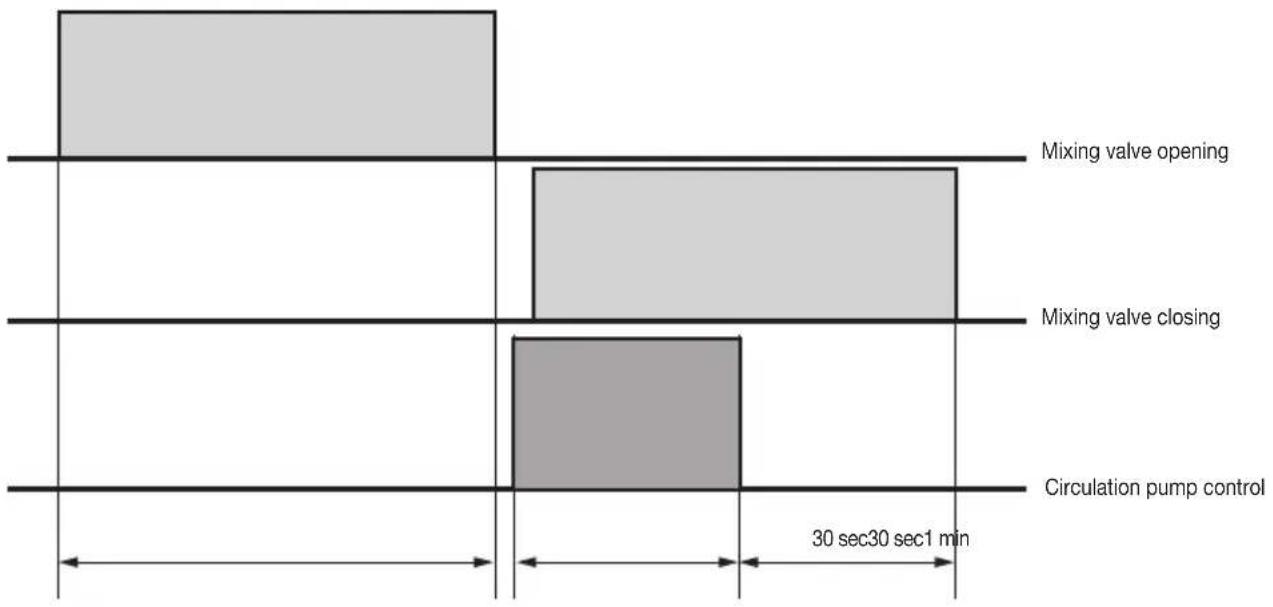
other
| Condition | Duration (sec) | | ----------------------- | -------------- | | Mixing valve opening | 30 sec | | Mixing valve closing | 30 sec | | Circulation pump control| 30 sec |Configuration on the controller
4. Air-conditioning control.
The air-conditioning is controlled in the system by means of the thermostats 02951, the temperature probes 20538-19538-14538 and the climate controller 01465; this chapter describes the operating modes which can be used and the procedures for setting the automatic programmes.
4.1 Operating modes.
The operating modes are selected using the menu:
HVAC → Select, moving 📋 to the left (<) or to the right (>) , the zone in which to set the mode
Touching 🖱️ 🖼️ displays the list with the operating modes; select the desired one by touching 🖼️ the corresponding word.
Depending on the device that controls the zone, the available modes will be as follows:
Touch screen thermostat 02951 and temperature probe 20538-19538-14538
- OFF = off.
- PROTECTION = Depending on whether in heating mode (winter) or cooling mode (summer), the thermostat activates the Antifreeze or Too hot safeguards respectively, which prevent the risk of damaging the system.
- REDUCTION = manual temperature typically used at night (e.g. 18^ in winter).
- MANUAL = is the classic operation of traditional thermostats (the desired temperature is set manually with no time limit).
- TIMED MANUAL = as above, for a selectable number of hours after which the thermostat returns to the previous operation.
- AWAY = lets the operator set the set-point in order to achieve significant energy savings during periods when the user is away.
• AUTOMATIC Activates weekly programming that has previously been configured on the control panel.
Note. If a Timed mode is selected, the control unit stores the previous mode and returns to this mode after the set time has elapsed.
Climate controller for heating systems (art. 01465)
- AUTOMATIC = activates a weekly programming that has previously been configured on the control panel.
- COMFORT = is the classic operation of traditional thermostats (the desired temperature is set manually with no time limit).
- ECONOMY = manual temperature typically used at night.
- OFF = off.
- Touching ⏻ the set point is manually forced; according to the type of operation mode set in the climate controller it may be:
- Fixed Mode: delivery temperature set point.
- ModulatingMode: desired ambient temperature set point.
IMPORTANT: The incorrect setting of this value may prevent the controller delivery valve from opening.
Configuration on the controller
4.2 Setting the speed of the fan coils
There are two methods of adjustment: manual and automatic.
- on selecting manual mode the user sets the desired speed;
- on selecting automatic mode the speed is adjusted by the thermostat according to the difference between the ambient temperature and the set point; the greater the difference the greater the speed.
HVAC → Select the desired zone → Fan coil speed → Select the desired speed:
- Minimum
- Medium
- Maximum
- Automatic
Touch lastly Save to confirm; after a time out the selected speed will be set.
4.3 Forced switch-off.
In certain situations, it may be necessary to force the air-conditioning system to switch off (for example, if the windows are opened).
To activate the function, the Plug&Play devices (art. 01470, 01475, 01476 and 01477) or the contacts interfaces (art. 20515-20518, 19515-19518 and 14515-14518) may be used, including them in the same group as the thermostat (or temperature sensor or climate control) and the relay.

flowchart
graph TD
    A["CONTROL UNIT"] -->|setpoint THERMOSTAT| B(( ))
    B -->|on/off| C["CONTACT INTERFACE"]
    B -->|on/off| D["RELAY"]
The control unit display shows an icon that indicates that the thermostat has been forced OFF.
Configuration on the controller
4.4 Programming.
This section describes the procedures for setting personalized air-conditioning programs for the 40 zones.
4.4.1 Setting the automatic program
The By-me system can be used to create personalized programs for automatic heating or air-conditioning control. The personalization consists of setting the value of a temperature level - that can be selected from between three different ones (T1, T2 and T3) - every 20 minutes; in the heating and air-conditioning programs the values T1, T2 and T3 are differentiable.
Select the zone to be programmed.
HVAC → Setup → Programming zones → Select the HVAC zone → Programs
Select the program to be created:
Heating prog.
Air-conditioning prog.
Select the day associated with the program to make then touch Edit program.

- With (or), set the time slot when to change the temperature level.
- With upwards or downwards, select the desired level of temperature from the three available ones (icons T1, T2 and T3); the histogram will be updated.
Touch 🤒 C, if you want to expand the set level T1,T2 o T3 forwards or backwards; if C is not selected/activated each movement will not alter the current setting.
- Repeat the procedure for all time slots to be changed, then confirm with Set.
Move onto another day of the week and proceed as above; using Copy from....., it is possible to assign the selected day with the program of any other day of the week; then select the day to copy and touch 📋 Set. Save the configuration with Save.
4.4.2 Setting temperature levels.
HVAC → Setup → Programming zones → Select the HVAC zone → Temperature levels
Select:
Heat. T1 [°C], Heat. T2 [°C], Heat. T3 [°C] or Air-con. T1 [°C], Air-con. T2 [°C], Air-con. T3 [°C]
Insert the desired value and confirm with Set; at the end of the operation touch Save.
The control unit confirms the operation carried out and returns to displaying the page with the settings of the programs relating to the previously selected temperature zone.
Example of installation
4. Example of installation
The following pages illustrate all the types of configurations using the thermostat (the examples are in any case valid for the temperature probe).
Legend

IMPORTANT: When configuring a circulation pump relay, the first time you must enter the menu Device parameters → Operation and:
- select "Hot circulation or circulation pump" if there is only one pump or it is effectively the hot one;
- select "Cold circulation or circulation pump" if the pump is the cold one;
N.B. In the following applications the relay actuators used are indicative only; indeed, when the control is "Valve on/off" type, any kind of actuator can be configured.
Example of installation
■ RADIATORS
In the winter the radiators are the main outputs of the system, while in the summer they are switched off.

flowchart
graph LR
    A["Functional Unit Output\nVALVE ON/OFF"] --> B["Device 1\n01693.2\n54710.1\nAUTOMATOR\n120-232V\nCOS"]
    B --> C["Color Grid"]
In the controller menu select: Configuration → Groups → Climate → Create group
- 1st Group - Thermostat
Add → Press the areas on the thermostat display that act as configuration buttons → Select:
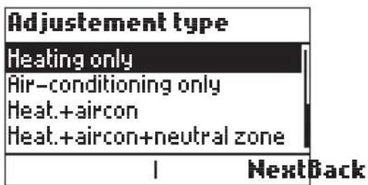
• 2nd Group - Radiator control
Add → Press the areas on the thermostat display that act as configuration buttons → Select:
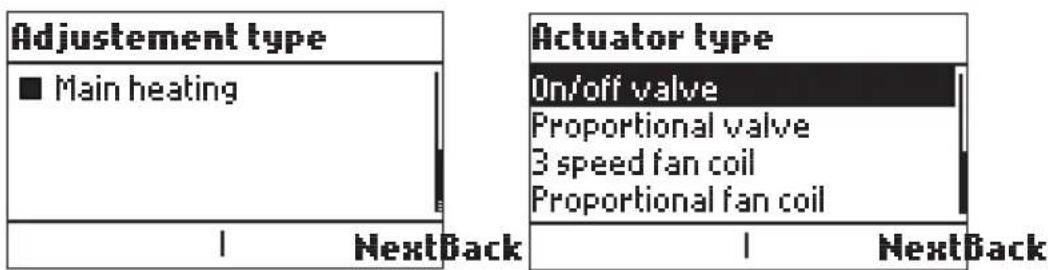
Add → Press the actuator configuration button 01850.2
If the actuator does not correspond to the selection made (in this case any By-me relay for controlling the On/Off Valve), the procedure ends by signalling an error.
Example of installation
■ 2 PIPE FLOOR HEATING
In the summer the floor heating works in cooling mode while in the winter in heating mode.
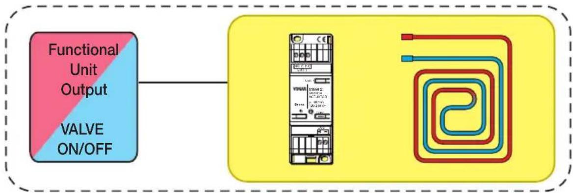
flowchart
graph LR
    A["Functional Unit Output\nVALVE ON/OFF"] --> B["Device with 150Hz IC, 2.5V AC, 3.5V DC, 4.5V E, 5.5V F"]
    B --> C["Output Circuit Diagram"]
In the controller menu select: Configuration → Groups → Climate → Create group
- 1st Group - Thermostat
Add → Press the areas on the thermostat display that act as configuration buttons → Select:
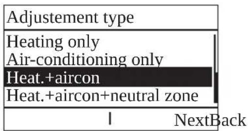
• 2nd Group - Floor heating circuit control
Add → Press the areas on the thermostat display that act as configuration buttons → Select:

flowchart
graph TD
    A["Adjustment type"] --> B["Main heating"]
    A --> C["Main air-conditioning"]
    D["NextBack"] --> E["1"]

Add → Press the actuator configuration button 01850.2
If the actuator does not correspond to the selection made, the procedure ends by signalling an error.
Example of installation
■ RADIATORS + AIRCON
In the summer the radiators are switched off and the aircon is switched on.
Vice versa, in the winter the radiators are the main outputs of the system while the aircon is switched off.
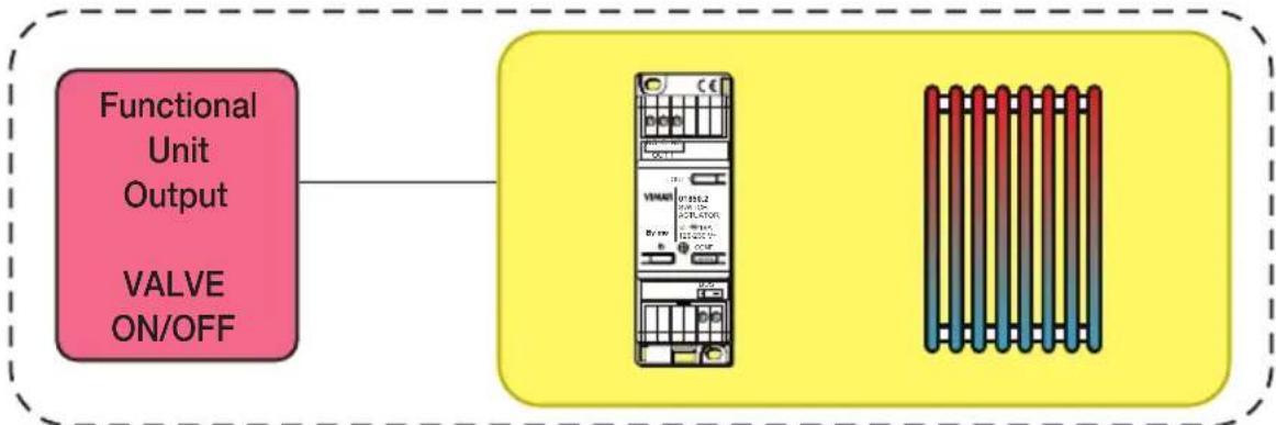
flowchart
graph LR
    A["Functional Unit Output\nVALVE ON/OFF"] --> B["Valve"]
    B --> C["Rack-mounted Server"]
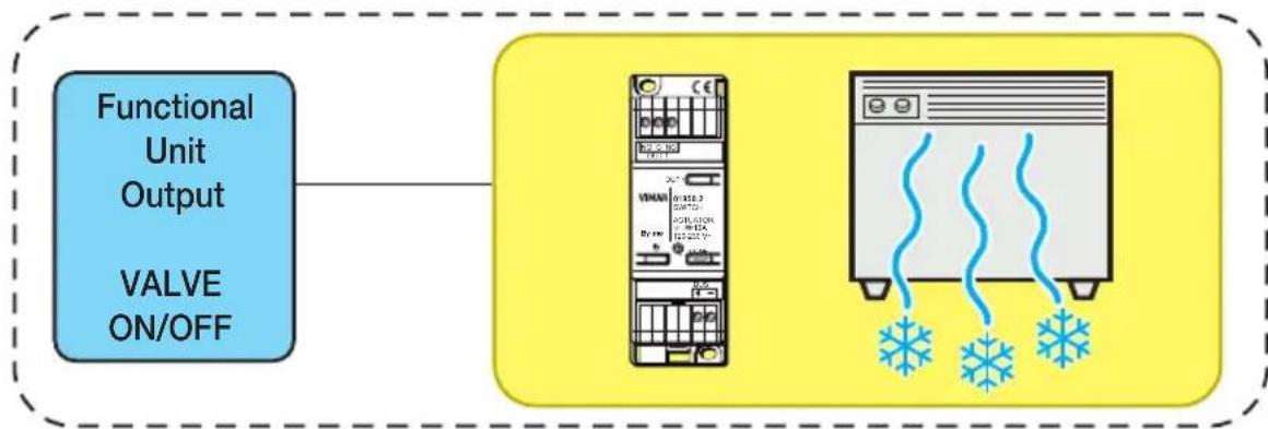
flowchart
graph LR
    A["Functional Unit Output\nVALVE ON/OFF"] --> B["Server with LED indicators"]
    B --> C["Server with snowflake graphics"]
In the controller menu select: Configuration → Groups → Climate → Create group
- 1st Group - Thermostat
Add → Press the areas on the thermostat display that act as configuration buttons → Select:

• 2nd Group - Radiator control
Add → Press the areas on the thermostat display that act as configuration buttons → Select:
Example of installation
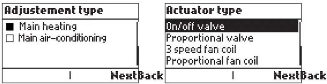
Add → Press the actuator configuration button 01850.2
If the actuator does not correspond to the selection made, the procedure ends by signalling an error.
• 3rd Group - Aircon control
Add → Press the areas on the thermostat display that act as configuration buttons → Select;

Add → Press the actuator configuration button 01850.2
If the actuator does not correspond to the selection made, the procedure ends by signalling an error.
Example of installation
■ PROPORTIONAL RADIATORS + AIR-CON (VIA SPLIT IR)
In the summer the radiators are switched off and the aircon is switched on. Vice versa, in the winter the radiators are the main outputs of the system while the aircon is switched off.

flowchart
graph LR
    A["Functional Unit Output\nPROP. VALVE"] --> B["Device 1: 01-488\n24-00C\n37-00V\n12-00V~500V/Hz\nP=0.5T\n3.72mA~3.90mA~2.0mA\nCE"]
    B --> C["Terminal Block 1"]
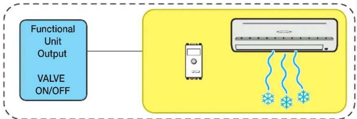
flowchart
graph LR
    A["Functional Unit Output"] --> B["Valve ON/OFF"]
    B --> C["Air Conditioner"]
    C --> D["Receiving Snow"]
In the controller menu select: Configuration → Groups → Climate → Create group
- 1st Group - Thermostat
Add → Press the areas on the thermostat display that act as configuration buttons → Select:

• 2nd Group - Radiator control
Add → Press the areas on the thermostat display that act as configuration buttons → Select:
Example of installation
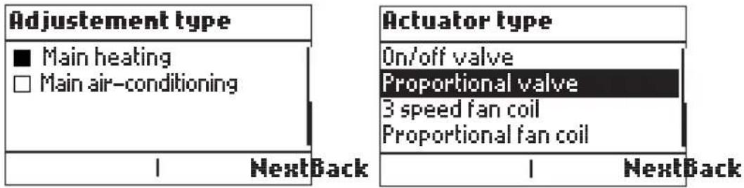
Add → Press the configuration button on the proportional actuator 01466
If the actuator does not correspond to the selection made, the procedure ends by signalling an error.
• 3rd Group Aircon control
Add → Press the areas on the thermostat display that act as configuration buttons → Select:

Add → Press the configuration button on the IR interface 20584.1-19584.1-14584.1
If the actuator does not correspond to the selection made, the procedure ends by signalling an error.
Example of installation
■ PROPORTIONAL RADIATORS + AIR-CON
In the summer the radiators are switched off and the aircon is switched on. Vice versa, in the winter the radiators are the main outputs of the system while the aircon is switched off.

flowchart
graph LR
    A["Functional Unit Output\nVALVE PROP."] --> B["Device with 01:466, 02:502, 03:508, 04:512, 05:516, 06:520, 07:524, 08:528, 09:532, 10:536, 11:539, 12:542, 13:546"]
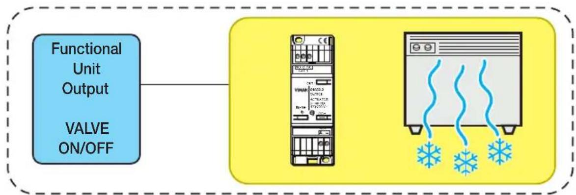
flowchart
graph LR
    A["Functional Unit Output\nVALVE ON/OFF"] --> B["Server"]
    B --> C["Refrigeration Device"]
In the controller menu select: Configuration → Groups → Climate → Create group
- 1st Group - Thermostat
Add → Press the areas on the thermostat display that act as configuration buttons → Select:
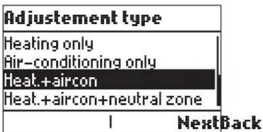
• 2nd Group - Radiator control
Add → Press the areas on the thermostat display that act as configuration buttons → Select:
Example of installation
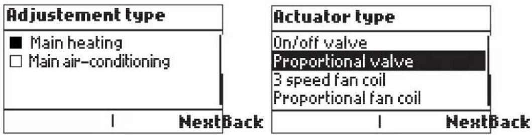
Add → Press the configuration button on the proportional actuator 01466
If the actuator does not correspond to the selection made, the procedure ends by signalling an error.
• 3rd Group Aircon control
Add → Press the areas on the thermostat display that act as configuration buttons → Select:

Add → Press the configuration button on the proportional actuator 01850.2
If the actuator does not correspond to the selection made, the procedure ends by signalling an error.
Example of installation
■ SYSTEM WITH 2 FANCOIL PIPES
As there is only one zone valve, used for heating or cooling according to the temperature of the water circulating in the pipes, we use relay actuator 01851.2.
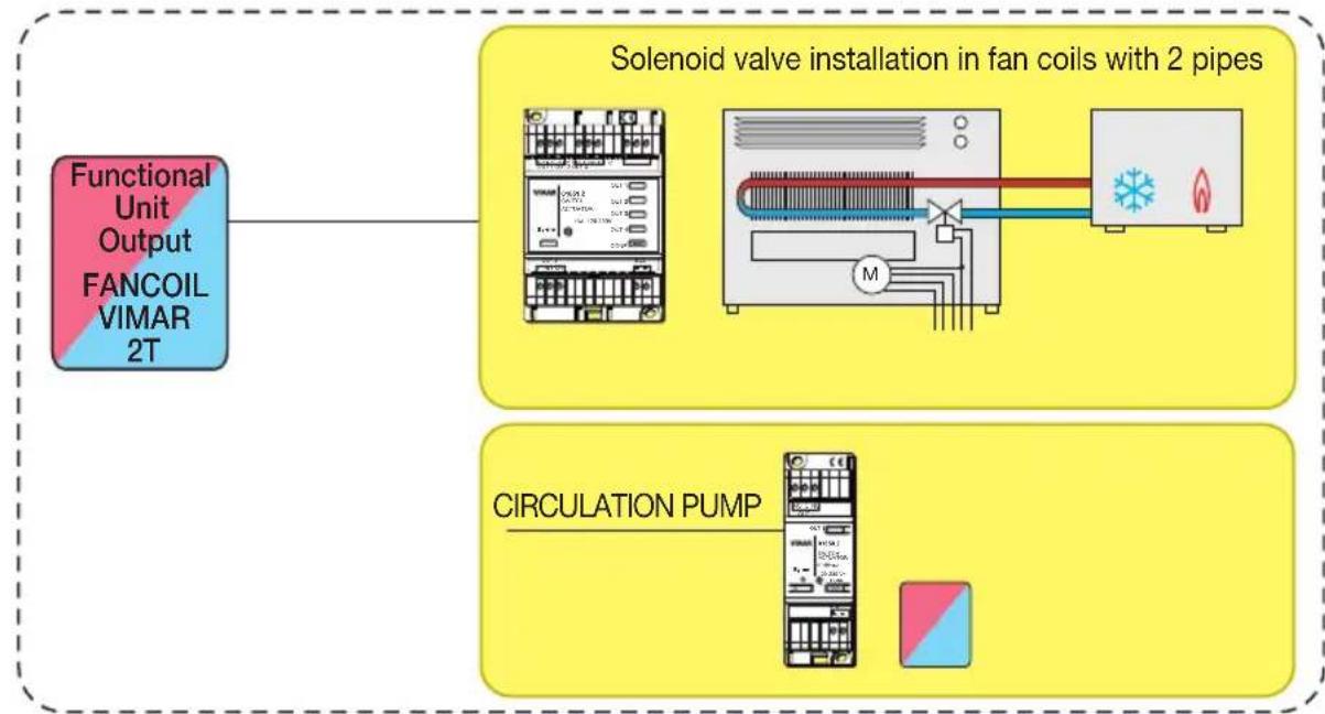
flowchart
graph TD
    A["Functional Unit Output FANCOIL VIMAR 2T"] --> B["Solenoid valve installation in fan coils with 2 pipes"]
    B --> C["CIRCULATION PUMP"]
In the controller menu select: Configuration → Groups → Climate → Create group
• 1st Group - Thermostat
Add → Press the areas on the thermostat display that act as configuration buttons → Select:

• 2nd Group - Faincoil control
Add → Press the areas on the thermostat display that act as configuration buttons → Select:
Example of installation
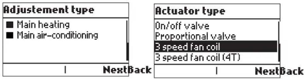
Add → Press the actuator configuration button 01851.2
The controller automatically configures all 4 functional units of the actuator 01851.2; no other configuration of this actuator is required.
The output connections of actuator 01851.2 are fixed and have the following meanings:
Out1 = V1
Out2 = V2
Out3 = V3
Out4 = valve
If the actuator does not correspond to the selection made, the procedure ends by signalling an error.
Add → Press the configuration button on actuator 01850.2 that acts as a circulation pump
If the actuator does not correspond to the selection made, the procedure ends by signalling an error.
Example of installation
■ SYSTEM WITH 2 PIPE FANCOIL + RADIATORS
In the summer the radiators are off while the fancoil is the main output for cooling.
In the winter the radiators are the main outputs for heating while the fancoil is the auxiliary output for the boost.

flowchart
graph LR
    A["Functional Unit Output FANCOIL VIMAR 2T"] --> B["Solenoid valve installation in fan coils with 2 pipes"]
    B --> C["Electrical module with AC/DC power lines and motor connection"]

flowchart
graph LR
    A["Functional Unit Output\nVALVE ON/OFF"] --> B["Device"]
    B --> C["Server Rack"]
In the controller menu select: Configuration → Groups → Climate → Create group
• 1st Group - Thermostat
Add → Press the areas on the thermostat display that act as configuration buttons → Select:

• 2nd Group - Faincoil control
Add → Press the areas on the thermostat display that act as configuration buttons → Select:
Example of installation

Add → Press the actuator configuration button 01851.2
If the actuator does not correspond to the selection made, the procedure ends by signalling an error.
• 3rd Group - Radiator control
Add → Press the areas on the thermostat display that act as configuration buttons → Select:

Add → Press the actuator configuration button 01850.2
If the actuator does not correspond to the selection made, the procedure ends by signalling an error.
Example of installation
■ SYSTEM WITH 4 PIPE FANCOIL
There are two valves so we use relay actuators 01851.2 and 01850.2.

flowchart
graph TD
    A["Functional Unit Output FANCOIL VIMAR 4T"] --> B["Solenoid valve installation in fan coils with 4 pipes"]
    B --> C["CIRCULATION PUMP"]
    B --> D["CIRCULATION PUMP"]
In the controller menu select: Configuration → Groups → Climate → Create group
• 1st Group - Thermostat
Add → Press the areas on the thermostat display that act as configuration buttons → Select:

Important: In the Neutral Zone adjustment mode, the thermostat automatically switches between heating and cooling according to the set set-point, the temperature measured and considering any neutral zone around the set point defined by the Neutral Zone Range parameter (set from 1°C to 5°C in 1°C steps).
For example, if the set point is set to 20^ C and the neutral zone range is 2^ C, the thermostat will switch the heating on if the temperature falls below 19^ C (set point – neutral zone range/2) and will switch on the air conditioning if the temperature rises above 21^ C (set point + neutral zone range/2). In this way a band of 2^ C around which the thermostat neither heats or cools is defined (thus the name neutral zone).
Example of installation
Important:
-The "neutral zone" adjustment can of course be used only on 4-pipe systems (which can both heat and cool at the same time).
- In the neutral zone adjustment mode, the thermostat only allows Manual and OFF operating modes.
• 2nd Group - Fain coil control
Add → Press the areas on the thermostat display that act as configuration buttons → Select:

flowchart
graph TD
    A["Adjustment type"] --> B["■ Main heating"]
    A --> C["■ Main air-conditioning"]
    D["1"] --> E["NextBack"]
Add → Press the actuator configuration button
In this case we must add an actuator 01851.2 and an actuator 01850.2 to the group
The controller automatically configures all 4 functional units of the actuator 01851.2 and the functional unit of actuator 01850.2; no other configuration of these actuator is required.
The output connections of actuator 01851.2 are fixed and have the following meanings:
Out1 = V1
Out2 = V2
Out3 = V3
Out4 = Hot Valve
While for actuator 01850.2 the output connection has the following meaning:
Out1 = Cold Valve
If the actuator does not correspond to the selection made, the procedure ends by signalling an error.
Add → Press the configuration button on actuator 01850.2 that acts as a hot circulation pump In the menu Device parameters set Hot circulation pump.
Add → Press the configuration button on actuator 01850.2 that acts as a cold circulation pump In the menu Device parameters set Cold circulation pump.
If the actuators do not correspond to the selection made, the procedure ends by signalling an error.
Example of installation
■ SYSTEM WITH 4-PIPE FANCOIL + 4 FLOOR HEATING PIPES (HEATING + COOLING)
The floor heating is always the main output both in winter and in summer (works in cooling mode). The fancoil is always the auxiliary output (boost) in both seasons.
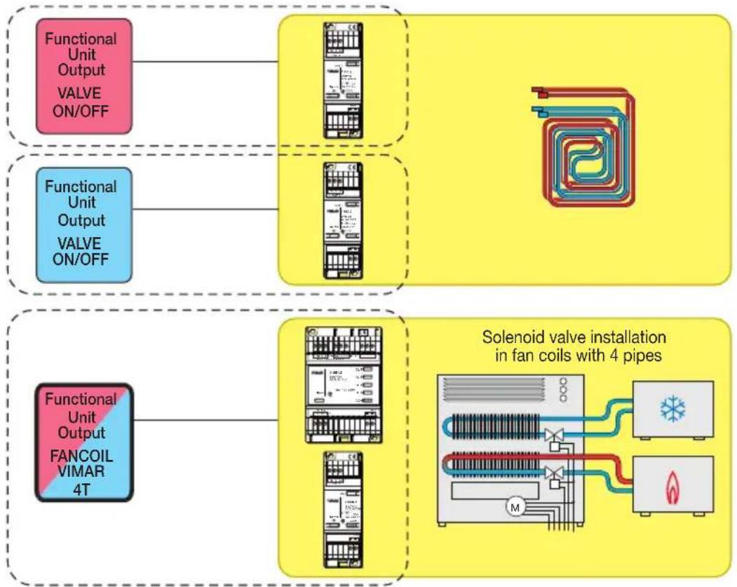
flowchart
graph TD
    A["Functional Unit Output\nVALVE ON/OFF"] --> B["Reactor"]
    C["Functional Unit Output\nVALVE ON/OFF"] --> D["Reactor"]
    E["Functional Unit Output\nFANCOIL VIMAR 4T"] --> F["Reactor"]
    G["Solenoid valve installation in fan coils with 4 pipes"] --> H["Reactor with M/Santernode"]
    H --> I["Reactor with Heat Exchanger"]
    H --> J["Reactor with Air Condition Sensor"]
In the controller menu select: Configuration → Groups → Climate → Create group
- 1st Group - Thermostat
Add → Press the areas on the thermostat display that act as configuration buttons → Select:

- 2nd Group
Add → Press the areas on the thermostat display that act as configuration buttons → Select:
Example of installation

Add → Press the actuator configuration button
If the actuator does not correspond to the selection made, the procedure ends by signalling an error.
- 3rd Group
Add → Press the areas on the thermostat display that act as configuration buttons → Select:
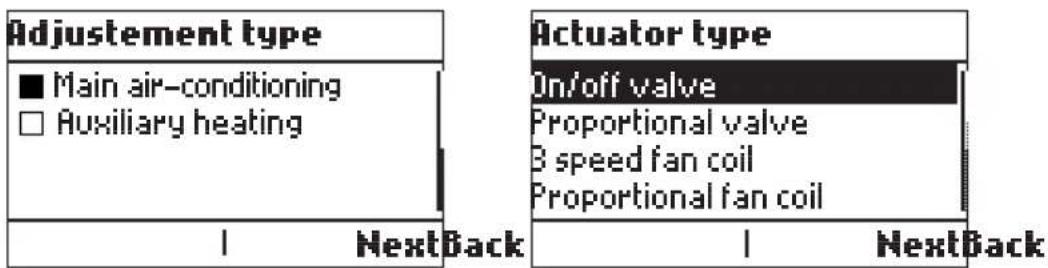
Add → Press the actuator configuration button
If the actuator does not correspond to the selection made, the procedure ends by signalling an error.
• 4th Group
Add → Press the areas on the thermostat display that act as configuration buttons → Select:

Add → Press the actuator configuration button
If the actuator does not correspond to the selection made, the procedure ends by signalling an error.
Example of installation
■ SYSTEM WITH 4 PIPE FANCOIL + FLOOR HEATING
In the summer the floor heating is switched off and the fancoil is the main output for cooling (using only the cold valve). In the winter the floor heating is the main output for heating while the fancoil is the auxiliary output for boost (using only the hot valve).
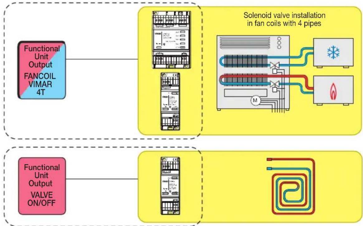
flowchart
graph TD
    A["Functional Unit Output FANCOIL VIMAR 4T"] --> B["Solenoid valve installation in fan coils with 4 pipes"]
    C["Functional Unit Output VALVE ON/OFF"] --> D["Valve Installation"]
In the controller menu select: Configuration → Groups → Climate → Create group
- 1st Group - Thermostat
Add → Press the areas on the thermostat display that act as configuration buttons → Select:

• 2nd Group - Heating/Cooling control
Add → Press the areas on the thermostat display that act as configuration buttons → Select:
Example of installation
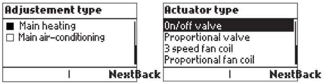
Add → Press the actuator configuration button 01850.2
If the actuator does not correspond to the selection made, the procedure ends by signalling an error.
• 3rd Group - Floor heating circuit control
Add → Press the areas on the thermostat display that act as configuration buttons → Select:

Add → Press the configuration button on actuator 01850.2 and actuator 01851.2
The controller automatically configures all 4 functional units of the actuator 01851.2 and the functional unit of actuator 01850.2; no other configuration of these actuator is required.
The output connections of actuator 01851.2 are fixed and have the following meanings:
$$ \text { Out1 } = \text { V1 } $$
$$ \text { Out2 } = \text { V2 } $$
$$ \text { Out3 } = \text { V3 } $$
$$ \text { Out4 } = \text { Hot Valve } $$
While for actuator 01850.2 the output connection has the following meaning:
$$ \text { Out1 } = \text { Cold Valve } $$
If the actuator does not correspond to the selection made, the procedure ends by signalling an error.
Example of installation
■ AIRCON WITH HEAT PUMP (VIA THE SAME SPLIT IR DEVICE)
In the summer we use the aircon while in the winter we use the same device but in heat pump mode.

flowchart
graph TD
    A["Functional Unit Output\nVALVE ON/OFF"] --> B["Functional Unit SPLIT IR"]
    C["Functional Unit Output\nVALVE ON/OFF"] --> D["Functional Unit SPLIT IR"]
    B --> E["Receiving Air Inlet"]
    D --> F["Receiving Air Inlet"]
BELONG TO THE
SAME DEVICE
In the controller menu select: Configuration → Groups → Climate → Create group
- 1st Group - Thermostat
Add → Press the areas on the thermostat display that act as configuration buttons → Select:

• 2nd Group - Aircon heat pump control
Add → Press the areas on the thermostat display that act as configuration buttons → Select:
Example of installation
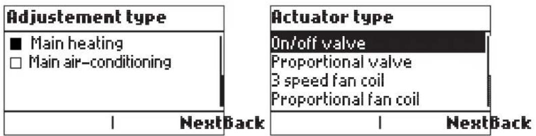
Add → Press the configuration button on the IR interface 20584.1-19584.1-14584.1
If the actuator does not correspond to the selection made, the procedure ends by signalling an error.
• 3r Group -Aircon control (cooling)
Add → Press the areas on the thermostat display that act as configuration buttons → Select:
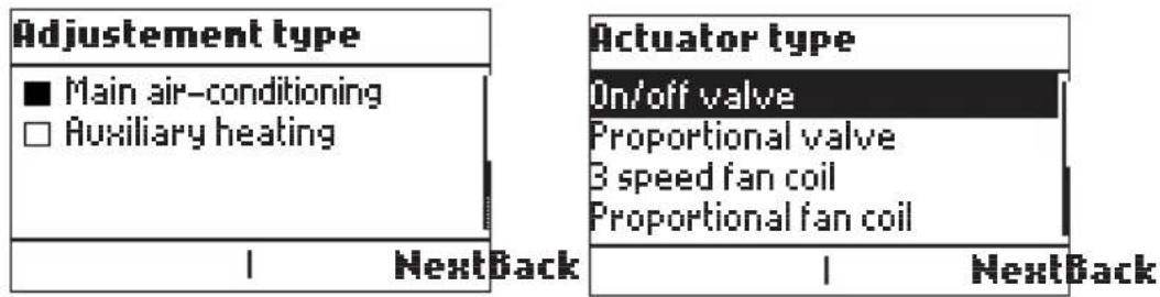
Add → Press the configuration button on the IR interface 20584.1-19584.1-14584.1
If the actuator does not correspond to the selection made, the procedure ends by signalling an error.
Example of installation
■ INTEGRATION METHODS
In this case the thermostat does not adjust the outputs, this is delegated to an external system via standard KNX messages.
Probes 1 and 2 are used to provide the external system with the ambient temperature and other information used to control the temperature in the temperature zone.
The thermostat user interface is used to control the external system and display the relative information.
In the controller menu select: Configuration → Groups → Climate → Create group
- 1st Group - Thermostat
Add → Press the areas on the thermostat display that act as configuration buttons → Select:
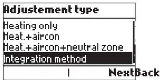

- If Heating only, Heating+aircon or Heating+aircon+neutral zone is selected, the following is displayed:

- If Aircon only, Heating+aircon or Heating+aircon+neutral zone is selected, the following is displayed:

Select the desired option → Next; the thermostat configuration will then start.
Example of installation
■ SYSTEM WITH CLIMATE CONTROLLER IN FIXED MODE
IMPORTANT: THE DIAGRAM SHOWN HERE IS PURELY INDICATIVE AND MUST BE APPROVED BY THE TECHNICAL THERMAL STUDY.

flowchart
graph TD
    subgraph_Zone1["Zone 02951 20538"]
        A1["Delivery probe"] --> B1["Circulation pump"]
        B1 --> C1["Mixer valve"]
        C1 --> D1["Boiler"]
    end
    subgraph_Zone2["Zone 02951 20538"]
        A2["Delivery probe"] --> B2["Circulation pump"]
        B2 --> C2["Mixer valve"]
        C2 --> D2["Boiler"]
    end
    subgraph_Zone3["Zone 02951 20538"]
        A3["Delivery probe"] --> B3["Circulation pump"]
        B3 --> C3["Mixer valve"]
        C3 --> D3["Boiler"]
    end
    subgraph_Output["Output signaling alarm"]
        D1 --> E1["OUT 1 OUT 2 OUT 3"]
        D2 --> E2["OUT 1 OUT 2 OUT 3"]
        D3 --> E3["OUT 1 OUT 2 OUT 3"]
    end
    style Zone1 fill:#f9f,stroke:#333
    style Zone2 fill:#f9f,stroke:#333
    style Zone3 fill:#f9f,stroke:#333
    style Output fill:#ccf,stroke:#333
    style T2 fill:#cfc,stroke:#333
    style T3 fill:#fcc,stroke:#333
Example of installation
■ SYSTEM WITH CLIMATE CONTROLLER IN MODULATING MODE
IMPORTANT: THE DIAGRAM SHOWN HERE IS PURELY INDICATIVE AND MUST BE APPROVED BY THE TECHNICAL THERMAL STUDY.

flowchart
graph TD
    A["Boiler"] --> B["Exterior"]
    B --> C["External probe"]
    C --> D["T1"]
    D --> E["01465 OUT 2"]
    E --> F["T2"]
    F --> G["Delivery probe"]
    G --> H["02951 BUS"]
    H --> I["18.2°C"]
    style A fill:#f9f,stroke:#333
    style B fill:#ccf,stroke:#333
    style C fill:#cfc,stroke:#333
    style D fill:#fcc,stroke:#333
    style E fill:#cff,stroke:#333
    style F fill:#ffc,stroke:#333
    style G fill:#cfc,stroke:#333
    style H fill:#fcc,stroke:#333
Climate control using the thermostats Idea 16953-16954
6. Climate control using the thermostats Idea 16953-16954.
The control unit can control up to 40 thermostats in timer-thermostat mode 16953 -16954 permitting programmed control of up to 40 different zones. Timer-thermostat functions:
- Automatic operation: 2 separate temperature programs (one for heating and one for air-conditioning on 3 temperature levels) for each of the 40 controlled zones.
- Manual operation: temperature setting between 5.0°C and 30.0°C (heating) and between 10°C and 35°C (air-conditioning).
- Timed manual operation (up to 99 hours).
- Reduction: temperature setting between 5.0^ and 30.0^ (heating) and between 10^ and 35^ (air-conditioning).
- Timed reduction (up to 99 hours).
- Antifreeze (temperature value adjustable from 0^ to 15.0^ ).
- Timed off (up to 99 hours).
- Off.
- Adjusting the speed of the fan-coils with the thermostats 20513, 16953 and 14513. and from the control unit
6.1 Zone management
This paragraph describes the procedures for creating and managing the HVAC zones of the By-me system.
6.1.1 Creating an HVAC group.
Used to define the 40 HVAC zones to be controlled, by selecting the related groups.
It is firstly necessary to define the HVAC zones to be controlled, by selecting the groups involved.
First of all it is necessary to create a new group:
Setup → Configuration → Groups → HVAC control groups
Within the group, configure a single thermostat device and at least one relay actuator; in addition, it is also possible to configure one or more control interfaces that, for instance, will detect a window opening (via magnetic contact) and will switch off the heating/air-conditioning system (see paragraph 5.2.1).
The configuration procedure is identical to that used in the Automation groups menu; to configure the thermostat press button A on the device (the first one on the left) thus displaying the CNF icon blinking.
N.B. It is recommended to assign short names for the rooms to control.
6.1.2 Creating an HVAC zone
From the main menu move into the HVAC menu
HVAC → Zone management → Add
- New zone index (00-40); set the number that unambiguously identifies the zone and touch 🤒 Next to confirm.
- Group association; select, from the list of HVAC groups, the group to associate with the zone just created. If there are no HVAC groups available to be able to be associated with the zone, a screen will be displayed with only the --- icon.
Climate control using the thermostats Idea 16953-16954
Therefore, to create a new zone, it is first necessary to create at least another HVAC group.
Touch Lastly Next to confirm; the control unit will confirm the operation.

6.1.3 Associating an HVAC group to a zone already configured
Used to change the association of the groups with zones previously configured.
HVAC → Setup → Zone management → Select the HVAC zone → Settings → Associated group → Select the HVAC group to associate with the zone → Set
In this case too, if there are no HVAC groups available to be able to be associated with the zone, a screen will be displayed with only the --- icon.
If the desired HVAC group is already associated with another zone, it is first necessary to cancel this association eliminating the corresponding zone.
Vice versa, if the group has not yet been created, it is first necessary to create the HVAC group.
The control unit confirms the operation and the display again shows the list of registered zones.
6.1.4 Zone activation.
Afterwards it is necessary to activate control of the zone with the control unit.
HVAC → Setup → Zone management → Select the HVAC zone → Settings → Central → management
Confirm with Set and save the setting by touching Save; the control unit shows the screen for HVAC zone management.
Selecting local deactivates control over the zone by the control unit; this zone can therefore be controlled only locally with the relevant thermostat.
6.1.5 Removing a zone
Used to remove the selected HVAC zone.
HVAC → Setup → Zone management → Select the HVAC zone to remove → Remove zone → Yes
The control unit confirms the deletion has been completed.
6.2 Zone Settings
This paragraph describes the procedures for setting the operating parameters of the various HVAC zones.
6.2.1 Heating or air-conditioning mode.
Used to set the operating mode of the system, making it possible to select the operating mode, for each zone, for either heating (winter period) or air-conditioning (summer period).
HVAC → Setup → Zone settings → Select the HVAC zone → Operation
Set the desired operation by selecting Heating or Air-conditioning and confirm with Set; after this operation touch Save.
The control unit confirms the operation performed and goes back to the settings for the HVAC zones.
N.B. When changing from Heating to Air-Conditioning mode and vice versa, the operating mode changes automatically to OFF.
Climate control using the thermostats Idea 16953-16954
6.2.2 Temperature differential.
Used to set the temperature differential of the system, and personalize it for each zone.
The temperature differential is the difference between the set temperature and the actual temperature of switching the system on or off. Adjusting the temperature differential to the type of system avoids continual switching on and off; high thermal inertia systems (for example systems with cast-iron radiators) need a low temperature differential, while low thermal inertia systems (for example fan heaters) need a high value.
HVAC → Setup → Zone settings → Select the HVAC zone → Temperature differential [°C]
Enter the desired value (from 0.1 to 1°C) and confirm with Set; at the end of the operation touch Save. The control unit confirms the operation performed and goes back to the settings for the HVAC zones.
Example.
If the ambient temperature is set to 20^ C and the temperature differential is set to 0.3^ C, the system will come on when the ambient temperature falls to 19.7^ C and will go off when it reaches 20.3^ C (in Heating mode).
6.2.3 Normal or protected operation.
The thermostats (Eikon 20513-20514, Arké 19513-19514, Idea 16953-16954, Plana 14153-14514) are used for local control (zone by zone) by the user. If the operating mode is set to “protected”, thermostat control is limited to switching off the system and setting the set-point within a pre-defined time, in order to prevent any unauthorized operations.
HVAC → Setup → Zone settings → Select the HVAC zone → Protection
Set the desired operation by selecting Off or On and confirm with Set; after this operation touch Save. The control unit confirms the operation performed and goes back to the settings for the HVAC zones.
The thermostat display will now show the padlock symbol.
N.B.
- When changing from "Normal" to "Protected" mode and vice versa, the operating mode changes automatically to OFF.
- The reference set-point must be set with the control unit.
As regards the normal or protected operation of the thermostat according to the selected mode, see the OPERATING MODE table on the instructions sheet of art. 20513, 16953, 14513.
6.2.4 Range of protection
If protected operation is set (see previous paragraph) it is necessary to define the range of protection (values from ±2 to ±5 ).
HVAC → Setup → Zone settings → Select the HVAC zone → Protection range [±°C]
Select the desired value and confirm with Set; at the end of the operation touch Save.
The control unit confirms the operation performed and goes back to the settings for the HVAC zones.
6.2.5 Type of system.
The thermostats for controlling the fan coils 16953 are used to manage the fan coils via the temperature control system.
These climate control devices need a control system to govern the speed of the fan and the opening of the valves for hot water (heating) or cold water (air-conditioning) circulation.
Climate control using the thermostats Idea 16953-16954
With just one type of climate control (heating or air-conditioning), the plumbing system is composed of two pipes, one for delivery and one for return.
With two types of climate control (heating and air-conditioning), the plumbing system is composed of four pipes, one for delivery and one for return for each function.
The main circulation pump/valve must be controlled with the actuator 01850.2 and this must be associated with all the temperature zones (that is it must be configured in all the climate control groups).
On creating the first group the operating mode must be set as circulation pump (it suffices to do this only on the first climate control group created).
The following figures illustrate the most commonly used types of system (2 pipes and 4 pipes) and the necessary steps for optimal operation.
SYSTEM WITH 2 PIPES - 1 ZONE
01851.2
OUT 1: FAN COIL SPEED V1
OUT 2: FAN COIL SPEED V2
OUT 3: FAN COIL SPEED V3
OUT 4 VALVE CONTROL
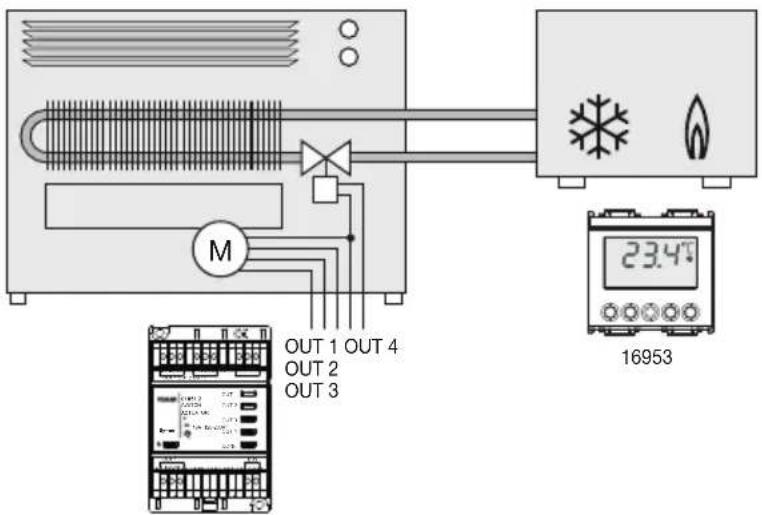
01851.2
Climate control using the thermostats Idea 16953-16954
SYSTEM WITH 2 PIPES - 4 ZONES

flowchart
graph TD
    A["01851.2"] --> B["OUT 1"]
    A --> C["OUT 2"]
    A --> D["OUT 3"]
    A --> E["OUT 4"]
    F["01850.2"] --> G["OUT"]
    H["M"] --> I["Zone 1"]
    H --> J["Zone 2"]
    H --> K["Zone 3"]
    H --> L["Zone 4"]
    I --> M["16953"]
    J --> N["16953"]
    K --> O["16953"]
    L --> P["16953"]
    M --> Q["N"]
    M --> R["L"]
    N --> S["16953"]
    O --> T["16953"]
    P --> U["16953"]
Climate control using the thermostats Idea 16953-16954
SYSTEM WITH 4 PIPES - 1 ZONE
01851.2
OUT 1: FAN COIL SPEED V1
OUT 2: FAN COIL SPEED V2
OUT 3: FAN COIL SPEED V3
OUT 4 VALVE CONTROL. "HOT"
01850.2
OUT: VALVE CONTROL "COLD"
SET PARAMETER "Cold Water Recirculation Pump"
N.B. OUT 4 OF 01851.2 SWITCHES OVER ONLY IF THE THERMOSTAT IS IN HEATING MODE (IT WILL CONTROL THE "HOT" VALVE OF THE FAN COIL) WHILE OUT OF 01850.2 SWITCHES OVER ONLY IF THE THERMOSTAT IS IN AIR-CONDITIONING MODE (IT WILL CONTROL THE "COLD" VALVE OF THE FAN COIL)

SYSTEM WITH 4 PIPES - 2 ZONES
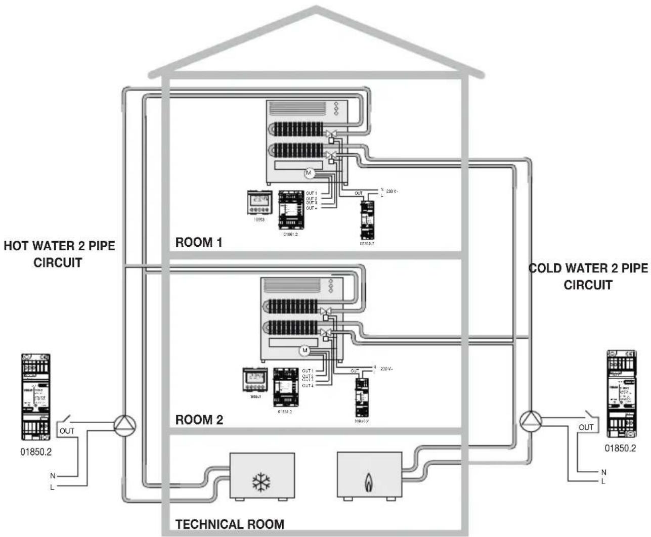
flowchart
graph TD
    subgraph Room 1
        A["Refrigerator 1"] --> B["Cinder"]
        B --> C["Pressure Gauge 2"]
        B --> D["Pressure Gauge 3"]
        B --> E["Pressure Gauge 4"]
        B --> F["Pressure Gauge 5"]
        B --> G["Main Circuit"]
        H["Main Circuit"] --> I["Cold Water 2 Pipe Circuit"]
    end

    subgraph Room 2
        J["Refrigerator 2"] --> K["Cinder"]
        K --> L["Pressure Gauge 1"]
        K --> M["Pressure Gauge 2"]
        K --> N["Pressure Gauge 3"]
        K --> O["Pressure Gauge 4"]
        K --> P["Pressure Gauge 5"]
        K --> Q["Main Circuit"]
        R["Main Circuit"] --> S["Cold Water 2 Pipe Circuit"]
    end

    subgraph Technical Room
        T["Technological Room"] --> U["Cathode"]
        U --> V["Light Bulb"]
        U --> W["Light Bulb"]
        U --> X["Light Bulb"]
        Y["Technical Room"] --> Z["Cathode"]
        Z --> AA["Light Bulb"]
        Z --> AB["Light Bulb"]
        AC["Technical Room"] --> AD["Cathode"]
        AD --> AE["Light Bulb"]
        AD --> AF["Light Bulb"]
        AG["Technical Room"] --> AH["Cathode"]
        AH --> AI["Light Bulb"]
        AH --> AJ["Light Bulb"]
        AK["Technical Room"] --> AL["Cathode"]
        AL --> AM["Light Bulb"]
        AL --> AN["Light Bulb"]
        AO["Technical Room"] --> AP["Cathode"]
        AP --> AQ["Light Bulb"]
        AP --> AR["Light Bulb"]
        AS["Technical Room"] --> AT["Cathode"]
        AT --> AU["Light Bulb"]
        AT --> AV["Light Bulb"]
        AW["Technical Room"] --> AX["Cathode"]
        AX --> AY["Light Bulb"]
        AX --> AZ["Light Bulb"]
        BA["Technical Room"] --> BB["Cathode"]
        BB --> BC["Light Bulb"]
        BB --> BD["Light Bulb"]
        BE["Technical Room"] --> BF["Cathode"]
        BF --> BG["Light Bulb"]
        BF --> BH["Light Bulb"]
        BI["Technical Room"] --> BJ["Cathode"]
        BJ --> BK["Light Bulb"]
        BJ --> BL["Light Bulb"]
        BM["Technical Room"] --> BN["Cathode"]
        BN --> BO["Light Bulb"]
        BN --> BP["Light Bulb"]
        BQ["HOT WATER 2 PIPE CIRCUIT"] --> R
    end

    style Room 1 fill:#f9f,stroke:#333
    style Room 2 fill:#f9f,stroke:#333
    style Technical Room fill:#ccf,stroke:#333
Climate control using the thermostats Idea 16953-16954
For the system with 4 pipes - 2 zones, the following applies:
ROOM 1 AND ROOM 2.
01851.2
OUT 1: FAN COIL SPEED V1
OUT 2: FAN COIL SPEED V2
OUT 3: FAN COIL SPEED V3
OUT 4 VALVE CONTROL. "HOT"
01850.2
OUT: VALVE CONTROL "COLD"
SET PARAMETER "Cold Water Recirculation Pump"
WARNING. OUT 4 OF 01851.2 SWITCHES OVER ONLY IF THE THERMOSTAT IS IN HEATING MODE (IT WILL CONTROL THE "HOT" VALVE OF THE FAN COIL) WHILE OUT OF 01850.2 SWITCHES OVER ONLY IF THE THERMOSTAT IS IN AIR-CONDITIONING MODE (IT WILL CONTROL THE "COLD" VALVE OF THE FAN COIL)
TECHNICAL ROOM.
THE ACTUATOR 01850.2 THAT CONTROLS THE HOT WATER 2 PIPE CIRCUIT MUST BE CONFIGURED IN ALL THE HVAC GROUPS; SET PARAMETER "Hot Water Recirculation Pump".
THE ACTUATOR 01850.2 THAT CONTROLS THE COLD WATER 2 PIPE CIRCUIT MUST BE CONFIGURED IN ALL THE HVAC
GROUPS; SET PARAMETER "Cold Water Recirculation Pump".
Relay actuator operating mode for a 2-pipe system.
- For each HVAC zone, install art. 01851.2 using outputs 1, 2 and 3 to control the fan coil, and output 4 for the valve.
- For the main circulation pump/valve, install art.01850.2 selecting mode "Hot Water Recirculation Pump".
Relay actuator operating mode for a 4-pipe system.
For each HVAC zone, install art. 01851.2 using outputs 1, 2 and 3 to control the fan coil, and output 4 for the "hot" valve; then install art. 01850.2 and use its outlet for the "cold" valve.
- For the "hot" delivery main circulation pump/valve, use art.01850.2 selecting mode "Hot Water Recirculation Pump".
- For the “cold” delivery main circulation pump/valve, use art.01850.2 selecting mode “Cold Water Recirculation Pump”.
If the HVAC zone is associated with a thermostat 20513,16953 or 14513, the control unit automatically suggests the parameter setting that permits selecting the type of system with two or four pipes.
HVAC → Setup → Zone settings → Select the HVAC zone → Type of system
Select the type of desired system (2 pipes or 4 pipes) and confirm with Set; at the end of this operation touch
Save. The control unit confirms the operation performed and goes back to the settings for the HVAC zones.

Climate control using the thermostats Idea 16953-16954
6.2.6 Select temperature zone to be displayed.
Used to set the zone to be displayed on the control unit when accessing the HVAC menu.
HVAC → Setup → Zone settings → Select the desired zone → Monitor zone → Select activated or deactivated
Confirm with Set and lastly touch 'Save.
The control unit confirms the operation performed and goes back to the settings for the HVAC zones.
After defining the temperature zone the HVAC menu will be displayed as illustrated in the following example:

- Touching Menu displays the control unit's main menu;
- Touching Setup displays the zone parameters;
- Touching 🖱️ 🎟 displays the thermostat operation mode (in this case Automatic);
- Touching manually forces the current temperature set point independently of the current operating mode
6.3 Operating modes.
This section describes the system operating modes that can be selected: Off, Timed Off, Antifreeze, Reduction, Timed Reduction, Manual, Timed Manual, Automatic.
Note.
If a Timed mode is selected, the control unit stores the previous mode and returns to this mode after the set time has elapsed.
HVAC → Select, moving 🖱️ to the left (<) or to the right (>) , the zone in which you want to set the mode Touching 🖱️ displays the list with the following operating modes:
• Automatic: used to set the temperature according to a pre-selected program in memory.
- Override: this option, which can be used when the timer-thermostat is operating on Automatic with daily or weekly programming, is used for temporarily changing a previously set temperature value within the program. This function is useful when, at a certain time, the desired temperature is different to the programmed one; in particular, it is possible to define a different temperature value to the one set in the program and for a time interval that can also be set.
- Manual: used to set the temperature according to the manually set point;
Climate control using the thermostats Idea 16953-16954
- Timed Manual: used to set manual mode for the desired period;
- Reduction: (night reduction/energy saving), used to set a lower temperature (heating) or higher temperature (air-conditioning) than the one in the automatic temperature control program, by selecting a value between 5°C and 30°C (heating) and between 10°C and 35°C (air-conditioning). The temperature is set according to the set point for temperature reduction.
- Timed reduction: used to set the reduced temperature for the desired period;
• Off: used to switch off the system; - Timed Off: used to switch off the system for the desired period;
- Antifreeze: used to set a minimum temperature level to avoid damage to pipework or prevent the temperature from falling below a safety level;
N.B.:
- It is not possible to pass from one type of operation to the timed equivalent.
- The Antifreeze function is not managed in Heating mode.
- Only the Off, Manual and Timed Manual functions are permitted in Protected mode.
6.3.1 Setting the speed of the fan coils
The fan coil speed setting is made using the thermostat 16953 and the procedures are similar to those described in par. 4.3.1 of this section.
6.3.2 Forced switch-off.
The procedures are similar to those described in par. 4.3.2 of this section.
6.4 Programming.
The procedures are similar to those described in par. 4.4 of this section.
Section
Plug&Play Home Automation System
Table of Contents
- General features 269
- Devices and functions 270
- Configuration in the control unit 271
3.1 Functional block selection and configuration 271
3.2 Devices and their functional blocks 272
3.2.1 Configuration of Module with 9 inputs and 8 outputs 01470....274
3.2.2 Configuration of Module with 3 digital inputs and 3 outputs to control LED 01475....275
3.2.3 Configuration of Module with 2 digital inputs, 1 roller shutter output and 2 outputs to control LED 01476 276
3.2.4 Configuration of Module with 2 digital inputs, 1 relay output and 2 outputs to control LED 01477 277
3.3 Setting/changing the parameters 279
3.3.1 Functional blocks and their parameters.... 279
3.4 Configuration of controls and actuators on multiple groups 283
- APPENDIX - Operation of actuators for art. 01470, 01471, 01476, 01477 ..... 285
Presentation of the system
1. General characteristics
The products in the Plug&Play home automation range offer a closed package of pre-configured solutions that enable converting a traditional system into a small home automation system dedicated to managing lights and roller shutters. These devices can be installed in "star point" or "distributed" systems, in existing buildings or ones under renovation, in residential and small commercial premises.
An installation with Plug&Play products can then be integrated in the By-me system allowing the addition of all the other functions available in the By-me range (supervision, comfort, security and energy efficiency); to achieve this integration, the Plug&Play products need to be configured via the control unit or the EasyTool Professional software, thus with no pre-configuration.
Devices and functions
2. Devices and functions
The devices that enable the Plug&Play home automation system functions are as follows:
 | 01470: Module with 9 inputs and 8 preprogrammed outputs, programmable digital inputs for potential-free contacts, N/O relay outputs 16 A 120-230 V~ 50/60 Hz programmable with control function for lights, roller shutters with slat orientation, push-buttons for local control, By-me home automation system, installation on DIN rails (60715 TH35), occupies 6 modules size 17.5 mm. |
 | 01475: Module with 3 programmable digital inputs for potential-free contacts, 3 outputs for LED control, By-me home automation system, flush mounting (retrofit). |
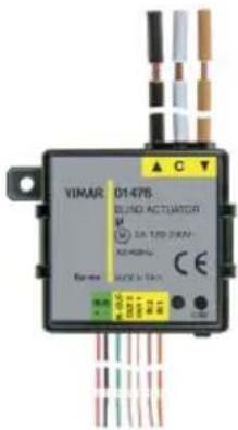 | 01476: Module with 2 programmable digital inputs for potential-free contacts, 1 output for a roller shutter with slat orientation with relay for motor cos φ 0.6 2 A 120-230 V~, 2 outputs for LED control, By-me home automation system, flush mounting (retrofit). |
 | 01477: Module with 2 programmable digital inputs for potential-free contacts, 1 lights control output with N/O relay 10 A 120-230 V~ 50/60 Hz, 2 outputs for LED control, By-me home automation system, flush mounting (retrofit). |
Configuration on the control unit
3. Configuration on the control unit
The main task to perform in order to configure the basic home automation system control devices on the control unit is to create functional groups (sets of functional blocks that need to work together) to which they are assigned.
The procedure to be carried out for each new group is as follows:
Setup → Configuration → Groups
Climate → Create group → Add
Create the selected group:
- Index of new group that identifies the number of the group in the list of all the configured ones; tap Next to confirm.
- New group name selecting, from among the names offered by a pre-set list, both the name of the group and the zone of application (necessary to distinguish between rooms and functions with the same name).
Lastly, proceed to save the name of the group by touching Save.
If the operation has been carried out correctly the control unit will show Operation completed successfully
By selecting the desired group it is possible to view the information related to the group such as the address and number of devices, the devices that may already be linked and to delete the group (Remove Group menu).
3.1 Functional block selection and configuration.
To configure the various functional blocks within a group, carry out the following:
- Tap Setup → Configuration → Groups
- Select the name of the group to which you want to add the functional block to configure.
- Once you have chosen the group, tap Associated devices Add; the procedure is started on the control unit.
- Select the functional block to be included in the group.
- The device indicates that configuration is in progress by means of a red LED, which goes off when configuration is complete.
- The control unit indicates the functional block that has just been configured.
- Proceed with the configuration of other functional blocks by repeating point 4 or tap 📋 Backto exit.
IMPORTANT: The scenes have a group depth of 4; this means that the same functional block can be enrolled in at most 4 scenes.
While saving scenes, the LEDs connected to the LED outputs of devices 01475, 01476, 01477 flash if they are involved in the scene.
Configuration on the control unit
3.2 Devices and their functional blocks
Description of the functional blocks
PUSH-BUTTON
- Button: to send ON and OFF messages over the bus as described in the "input behaviour" parameter. It is only with this functional block that traditional switches can be connected, in addition to buttons.
- Dimmer control: to control dimmer actuators.
- Roller shutter control: to control the functional block for roller shutters with no slats (as each command is the opposite of the previous one, each time you press and hold down the up/down movement of the roller shutters will change).
- Timer controlled command only*: to activate timer control
- Timer controlled* and ON/OFF command: to activate a timer controlled command or send an ON/OFF command, depending how the button is pressed (for example, short press for timed control and long press for ON/OFF)
- Scene control: to call up and save a scene.
- Send value: to send the value selected during configuration on the closure of the input.
- Sleep: to call up the sleep function in the speaker system.
- Audio monitoring: audio monitoring control (if associated with a microphone module device).
ROCKER BUTTON
- Rocker button: to send ON and OFF commands on the same group upon pressing input 1 or 2.
- Dimmer control: to control dimmer actuators.
- Roller shutter control: to control the roller shutter functional block (normal or with slats).
- Timer controlled command only*: to activate timer control
- Timer controlled* and ON/OFF command: to activate a timer controlled command or send an ON/OFF command, depending how the button is pressed (for example, short press for timed control and long press for ON/OFF)
• Volume OnOff: on/off and volume control for speaker system. - Sleep: to call up the sleep function in the speaker system.
- Ch+/Track+: ch+/track+ control for speaker system.
ACTUATOR
- Actuator: to manage a lights actuator.
This functional block receives the following command requests: load on/off, timed load switch on, saving and recalling scenes. - Timer controlled actuator: for control and also timer control of a lighting actuator.
Receives the following command requests: timer controlled load on/off, load on/off, scenario save and recall. - Circulation pump relay: for managing the circulation pump.
ROLLER SHUTTER ACTUATOR
- Roller shutter actuator: to manage the roller shutter.
- Blinds: to manage the roller shutter + slat
These functional blocks receive the following command requests: opening/closing roller shutters, rotating slats, setting the roller shutter height and slat rotation values, saving and recalling scenes, forcing via logic module.
* Configuration of the timer controlled command is only possible if there is at least one actuator in the group with the timer control function.
Configuration on the control unit
| Article | ||||
| Functional block | Module with 9 inputs and 8 outputs art. 01470 | Module with 3 digital inputs and 3 outputs to control LED art. 01475 | Module with 2 digital inputs, 1 roller shutter output and 2 outputs to control LED art. 01476 | Module with 2 digital inputs, 1 relay output and 2 outputs to control LED art. 01477 |
| Actuator | √ | √ | ||
| Roller shutter actuator | √ | √ | ||
| Blinds actuator | √ | √ | ||
| Push-button | √ √ √ | √ | ||
| Timer controlled command only | √ √ √ | √ | ||
| Timer controlled and ON/OFF command | √ √ √ | √ | ||
| Scene control | √ √ √ | √ | ||
| Rocker button | √ √ √ | √ | ||
| Push-button and Rocker button dimmer control, volume On/Off | √ √ √ | √ | ||
| Send value | √ √ √ | √ | ||
| Push-button and Rocker button roller shutter control | √ √ √ | √ | ||
| ch+/track+ | √ √ √ | √ | ||
| Circulation pump | √ | |||
| Sleep push-button and rocker button, audio monitoring push-button | √ √ √ | √ | ||
Configuration on the control unit
3.2.1 Configuration of Module with 9 inputs and 8 outputs 01470
Each input can be configured as a push-button and adjacent inputs (IN1+IN2, IN3+IN4, IN5+IN6, IN7+IN8) can be grouped for the rocker the function.
The relays can be used singularly or in pairs (OUT1+OUT2, OUT3+OUT4, OUT5+OUT6, OUT7+OUT8) to create the roller shutter outputs; relay 8 can be used for the circulation pump.
The rocker buttons and input functional blocks have a group depth of 1 (that is, they can belong to one group only).
FUNCTIONAL BLOCKS
- For each single relay, you can select the functional block:
- actuator
- timer controlled actuator
- For the pairs of relays (relay 1+ relay 2, relay 3 + relay 4, relay 5 + relay 6, relay 7 + relay 8) you can select one of the following functional blocks:
- roller shutter actuator
- blinds actuator
Caution: After installation you need to open and close each roller shutter completely to carry out the calibration process.
- For relay 8 you can choose the following functional block:
- circulation pump relay
- For the push-button logic function you can select one of the following functional blocks:
- push-button
- dimmer control
- roller shutter control
- timer controlled command only*
- timer controlled* and ON/OFF command
- scene control
- send value
- sleep (command for speaker system)
- audio monitoring (command for speaker system)
- For the rocker button logic function (input 1+2, input 3+4, input 5+6, input 7+8) you can select one of the following functional blocks (connect a double button such as art. 20066-19066-14066 and art. 20062-19062-14062):
- rocker button
- dimmer control
- roller shutter control
- timer controlled command only*
- timer controlled* and ON/OFF command
- Volume On/Off (volume control for speaker system)
- sleep (command for speaker system)
- ch+/track+ (command for speaker system)
* Configuration of the timer controlled command is only possible if there is at least one actuator in the group with the timer control function.
Configuration on the control unit
Selecting the functional block to be configured:
After pressing the configuration button, before the red LED lights up, choose one of the following options:
- Briefly press the OUT1 button to configure output 1, the OUT2 button to configure output 2, and so on; then the corresponding LED will switch on.
- Briefly press the OUT1 button + OUT2 button to configure the roller shutter output 1, the OUT3 button + OUT4 button to configure the roller shutter output 2 and so on; then the corresponding LEDs will switch on.
- Press and hold down the OUT1 button to configure input 1 as a push-button, press and hold the OUT2 button to configure input 2 as a push-button and so on until input and button OUT8; the corresponding LED will blink.
- Press and hold down the OUT1 button + OUT2 button to configure inputs 1 and 2 together as a rocker button, press and hold down the OUT3 button + OUT4 button to configure inputs 3 and 4 together as a rocker button and so on to the OUT7 button + OUT8 button to configure inputs 7 and 8 together as a rocker button; the corresponding LED will blink.
- Briefly press the button to configure relay 8 as a relay for the circulation pump; the corresponding LED will light up.
- Press and hold down button to configure input 9 as a push-button; the corresponding LED will blink.
After a pause of a few seconds the device enters configuration mode for the selected functional block and the start of configuration is signalled by the red LED. At the end of this operation the red LED will go out.
SCENES.
The actuator can belong to multiple scenes and, for each one of them, save the status (ON or OFF) to retrieve when activating the scene itself.
The roller shutter actuator can save and recall the height of the roller shutter.
The blinds actuator can save and recall the height of the roller shutter and the angle of the slats.
3.2.2 Configuration of Module with 3 digital inputs and 3 outputs to control LED 01475
The functional blocks that the device makes available comprise: 3 push-buttons or 1 rocker button + 1 push-button.
The push-button and rocker button functional blocks have a group depth of 1 (that is, they can belong to one group only).
FUNCTIONAL BLOCKS
- For the push-button logic function you can select one of the following functional blocks:
- push-button
- dimmer control
- roller shutter control
- timer controlled command only*
- timer controlled* and ON/OFF command
- scene control
- send value
- sleep (command for speaker system)
- audio monitoring (command for speaker system)
- For the rocker button logic function (composed of inputs 1 and 2) you can select one of the following functional blocks:
- rocker button
- dimmer control
Configuration on the control unit
- roller shutter control
- timer controlled command only*
- timer controlled* and ON/OFF command
- Volume On/Off (volume control for speaker system)
- sleep (command for speaker system)
- ch+/track+ (command for speaker system)
* Configuration of the timer controlled command is only possible if there is at least one actuator in the group with the timer control function.
Selecting the functional block to be configured:
Press the configuration button to select the first functional block; keeping it pressed cycles through the list of functional blocks.
The green LED indicates the current functional block:
• 1 flash for functional block button 1;
- 2 flashes for functional block button 2;
• 3 flashes for functional block button 3;
• LED on steady for the rocker button functional block.
After a pause of 3 s the device enters configuration mode for the selected functional block and the start of configuration is signalled by the red LED coming on and the green LED going out. At the end of this operation the red LED will go out.
SCENES.
The push-buttons and rocker buttons can belong to several different scenes and, for each of them, save the state of the associated LED.
During the scene identification phase the LEDs flash (only if actually connected to the output)
3.2.3 Configuration of Module with 2 digital inputs, 1 roller shutter output and 2 outputs to control LED 01476
The functional blocks that the device makes available comprise: 2 push-buttons or 1 rocker button, 1 roller shutter actuator.
The push-button and rocker button functional blocks have a group depth of 1 (that is, they can belong to one group only).
FUNCTIONAL BLOCKS
- For the push-button logic function you can select one of the following functional blocks:
- push-button
- dimmer control
- roller shutter control
- timer controlled command only*
- timer controlled* and ON/OFF command
- scene control
- send value
- sleep (command for speaker system)
- audio monitoring (command for speaker system)
Configuration on the control unit
- For the rocker button logic function (composed of inputs 1 and 2) you can select one of the following functional blocks:
- rocker button
- dimmer control
- roller shutter control
- Volume On/Off (volume control for speaker system)
- sleep (command for speaker system)
- ch+/track+ (command for speaker system)
- For the roller shutter you can select one of the following functional blocks:
- roller shutter actuator
- blinds actuator
Caution: After installation you need to open and close each roller shutter completely to carry out the calibration process.
* Configuration of the timer controlled command is only possible if there is at least one actuator in the group with the timer control function.
Selecting the functional block to be configured:
Press the configuration button to select the first functional block; keeping it pressed cycles through the list of functional blocks.
The green LED indicates the current functional block:
- 1 flash for functional block button 1;
- 2 flashes for functional block button 2;
- 3 flashes for the rocker button functional block;
- LED on steady for the roller shutter actuator functional block.
After a pause of a few seconds the device enters configuration mode for the selected functional block and the start of configuration is signalled by the red LED coming on and the green LED going out. At the end of this operation the red LED will go out.
SCENES.
The push-buttons and rocker buttons can belong to several different scenes and, for each of them, save the state of the associated LED.
During the scene identification phase the LEDs flash (only if actually connected to the output).
The roller shutter actuator can save and recall the height of the roller shutter.
The blinds actuator can save and recall the height of the roller shutter and the angle of the slats.
3.2.4 Configuration of Module with 2 digital inputs, 1 relay output and 2 outputs to control LED 01477
The functional blocks that the device makes available comprise: 2 push-buttons or 1 rocker button, 1 relay.
The push-button and rocker button functional blocks have a group depth of 1 (that is, they can belong to one group only).
FUNCTIONAL BLOCKS
- For the push-button logic function you can select one of the following functional blocks:
- push-button
- dimmer control
Configuration on the control unit
- roller shutter control
- timer controlled command only*
- timer controlled* and ON/OFF command
- scene control
- send value
- sleep (command for speaker system)
- audio monitoring
- For the rocker button logic function (composed of inputs 1 and 2) you can select one of the following functional blocks:
- rocker button
- dimmer control
- roller shutter control
- timer controlled command only*
- timer controlled* and ON/OFF command
- Volume On/Off (volume control for speaker system)
- sleep (command for speaker system)
- ch+/track+ (command for speaker system)
- For the relay, you can select the functional block: actuator, timer controlled actuator.
* Configuration of the timer controlled command is only possible if there is at least one actuator in the group with the timer control function.
Selecting the functional block to be configured:
Press the configuration button to select the first functional block; keeping it pressed cycles through the list of functional blocks.
The green LED indicates the current functional block:
• 1 flash for functional block button 1;
• 2 flashes for functional block button 2;
• 3 flashes for the rocker button functional block;
• LED on steady for the actuator functional block.
After a pause of 3 s the device enters configuration mode for the selected functional block and the start of configuration is signalled by the red LED coming on and the green LED going out. At the end of this operation the red LED will go out.
SCENES.
The push-buttons and rocker buttons can belong to several different scenes and, for each of them, save the state of the associated LED.
During the scene identification phase the LEDs flash (only if actually connected to the output).
The actuator can belong to multiple scenes and, for each one of them, save the status (ON or OFF) to retrieve when activating the scene itself.
Configuration on the control unit
3.3 Setting/changing the parameters.
Device parameters can be set and/or modified in order to customize operation to adapt the system to the various installation requirements.

3.3.1 Functional blocks and their parameters
Description of the parameters
ACTUATOR AND TIMER CONTROLLED ACTUATOR
- On and off delay (they are delay times that can be set for actuating the On and Off request): from 0 s to 12 h with default value 0 s.
- ON time duration for one-position stable operation (this is the activation time for one-position stable operation): from 1 s to 12 h with default value 30 s.
- Warning time (this is a time that is added to the activation time of the one-position stable actuator. At the end of the activation time the relay switches off for 0.5 s and then switches back on for the warning time): from 0 s to 12 h with default value 0 s.
- Output status at power on and output status at power down (this enables setting the actuator when switching off and upon restoring power respectively): ON/OFF/Unchanged with default value "Unchanged".
- Operation (this enables setting the operation of the actuator): one-position stable/two-position stable with default value "two-position stable".
- Feedback group (this enables setting the group on which to send the actuator status to align the LEDs of the commands): for details see par. 3.4
ROLLER SHUTTER AND BLINDS ACTUATOR
- Up and down time (these are the roller shutter up and down times): 10 s to 1 h with default value 180 s.
- Full slat rotation time: from 500 ms to 5 s with default value 2 s.
- Behaviour at power on (this enables setting whether when power is restored the roller shutter opens, closes, remains in the current position or you can choose the height of the roller shutter and the tilt of the slats): all down, all up, no action, default position. Default value no "action".
- Position of the roller shutter at power on (enables setting the position of the roller shutter when power is restored): from 0 to 100% with default value 50% .
- Scene recall execution delay (this enables delaying execution of the command so as not to actuate all the roller shutters at once): from 0 s to 250 s with default value 0 s.
- Command execution delay: from 0 s to 250 s with default value 0 s.
- Tilt of the slats at power on (enables setting the position of the slat when power is restored): from 0 to 100% with default value 50% .
- Position on forcing (this enables setting the behaviour of the roller shutter upon the forcing request): all down, all up, fixed, preset position with default value "fixed." It is necessary to observe the value set by the "roller shutter position on forcing" and "slat tilt on forcing" parameters.
- Position on end of forcing (this enables setting the behaviour of the roller shutter at the end of forcing): all down, all up, fixed, preset position with default value "fixed." It is necessary to observe the value set by the "roller shutter position on forcing" and "slat tilt on forcing" parameters; it returns to the previous value with the request for forcing.
Configuration on the control unit
- Roller shutter position on forcing (can be used in the “position on forcing” and “position on end of forcing” parameters): from 0 to 100% with default value 50%.
- Slat tilt on forcing (can be used in the "position on forcing" and "position on end of forcing" parameters): from 0 to 100% with default value 50% .
PUSH-BUTTON AND ROCKER BUTTON
- Command input report: normal push-button ON when closing, OFF when opening, reversed push-button OFF when closing, ON when opening, toggle on the rising edge, toggle on the falling edge, toggle on both edges (to be used when a conventional switch is connected to the input), only ON ON when closing, only OFF OFF when closing. Default value "Toggle on the rising edge".
- Enable scene saving (this parameter is for the scene recall button that enables choosing whether, for pressing and holding, the push-button sends a request for saving the current scene). Default value "Disabled".
- Long press time: from 0.5 s to 30 s with default value 0.5 s.
- Short/long press behaviour: normal or reversed with default value "normal." This parameter is useful also for actuators with the timer control function to invert the two ON/OFF and timer controlled commands.
-
Up/Down orientation:
-
(ON when closing input 1 and OFF when closing input 2 or vice versa).
- valid only for the dimmer control (ON and up when closing input 1 and OFF and down when closing input 2 or vice versa).
- valid only for the roller shutter push-button (roller shutter up when long closing input 1 and roller shutter down when long closing input 2 or vice versa).
- ch+ when closing input 1 and track+ when closing input 2 or vice versa.
- Output value (the value selected with this parameter is sent when the input closes): from 0 to 100% with default value 0% .
- LED control:
- For the push-button, for the dimmer control push-button, for the sleep and audio monitoring push-button: Normal = LED on if associated load active and off if load off; Reversed = LED off if associated load active and on if load off; always on; Disabled = always off.
- For the roller shutter push-button, for the scene control push-button and for the send value push-button: Normal = LED on for 3 s when closing the input; Reversed = LED off for 3 s when closing the input; always on: Disabled = always off.
- For the rocker button, for the dimmer control rocker button, for the sleep and ch+/track+ rocker button. Normal = output 1 LED on if associated load active and off if load off; Reversed = output 1 LED off if associated load active and on if load off; always on; Disabled = always off. In the Normal and Reversed cases, the LED of output 2 is inverted with respect to output 1.
- For the roller shutter rocker button: Normal = output 1 LED on for 3 s when closing the input 1; Reversed = output 1 LED off for 3 s when closing the input 1; always on; Disabled = always off.
N.B.: For the rocker button, if using a single LED, it is necessary to connect the latter to both outputs to get the closing feedback of both inputs.
CIRCULATION PUMP
- On delay: default 0 s.
- Off delay: default 0 s.
- Valve control (enables selecting whether to control the hot or cold valve). Default value "heating valve".
Configuration on the control unit
| Functional blocks | ||||||||||
| Parameter | Push-button | Dimmer control and roller shutter push-button | Timer controlled-pushbutton | Scene control | Send value | Push-button sleep and audio monitoring | Rocker button, sleep and ch+/track+ rocker button | Dimmer control, On/Off rocker button Volume and roller shutter | Timer controlled rocker switch | |
| Command input report | √ | |||||||||
| Enable scene saving | √ | |||||||||
| Comportamento pressione lunga/corta | √ | √ | ||||||||
| Time long press | √ √ | √ √ √ | ||||||||
| Output value | √ | |||||||||
| Orientation rocker button | √ | √ | ||||||||
| LED control | √ √ | √ √ | √ √ √ | √ √ | ||||||
| Operation* | √ | √ | ||||||||
* The "Operation" parameter can only be used when there is the speaker system (thus for the sleep, ch+/track+, volume On/Off functional blocks).
N.B.: For art. 01470 there is no LED Control parameter.
Configuration on the control unit
| Functional blocks | |||||
| Parameter Actuator | Timer controlled actuator | Roller shutter actuator | Blinds actuator | Pump for circulation | |
| On and off delay | √ √ | √ | |||
| On duration for one-position stable operation | √ | √ | |||
| Warning period | √ | √ | |||
| Output status at power on and at power down | √ | √ | |||
| Operation | √ | ||||
| Up and down time | √ | √ | |||
| Full slat rotation time | √ | ||||
| Scene control execution delay | √ | √ | |||
| Command execution delay | √ | √ | |||
| Behaviour at power ON | √ | √ | |||
| Roller shutter position at power on | √ | √ | |||
| Slat angle at power on | √ | ||||
| Position on forcing | √ | √ | |||
| Position on end of forcing | √ | √ | |||
| Roller shutter position on forcing | √ | √ | |||
| Slat angle on forcing | √ | ||||
| Valve check | √ | ||||
Configuration on the control unit
3.4 Configuration of controls and actuators on multiple groups
For articles 01470, 01471, 01475, 01476 and 01477, the command group depth is equal to 1 while for the actuators it is equal to 4; an actuator can then belong to 4 groups and 4 different scenes.
SIMPLE GROUP
A simple example of a command for a relay actuator is shown in Fig. 1 where a command sends a toggle request to a relay actuator and receives feedback on the latter's status.

flowchart
graph LR
    A["COMMAND"] -->|feedback On/Off On/Off feedback| B["RELAY ACTUATOR"]
    B --> C["..."]
Fig. 1
GROUP DEPTH ON THE ACTUATORS
Fig. 2 shows the interaction between two relay actuators configured in a group with its own command and a second group with a command that switches multiple loads on/off simultaneously
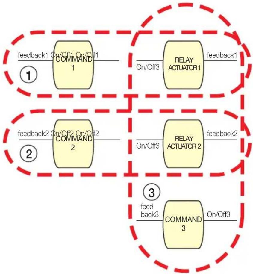
flowchart
graph TD
    subgraph_Block1["1"]
        A["COMMAND 1"] -->|feedback1 On/Off1 On/Off1| B["RELAY ACTUATOR 1"]
        B -->|feedback1 On/Off3| C["COMMAND 2"]
    end
    subgraph_Block2["2"]
        D["COMMAND 2"] -->|feedback2 On/Off2 On/Off2| E["RELAY ACTUATOR 2"]
        E -->|feedback2 On/Off3| F["COMMAND 3"]
    end
    subgraph_Block3["3"]
        G["COMMAND 3"] -->|feedback3| H["RELAY ACTUATOR 3"]
        H -->|feedback3 On/Off3| I["COMMAND 3"]
    end
Fig. 2
Configuration on the control unit
- On creating group 1:
- the relay actuator 1 is associated with the command 1
- the actuator output is given the address that indicates the status of the actuator (feedback 1)
- On creating group 2:
- the relay actuator 2 is associated with the command 2
- the actuator output is given the address that indicates the status of the actuator (feedback 2)
- On creating group 3:
- both relay actuators are associated with the command of group 3
At this stage, for each actuator, you can set the desired feedback group, ie towards which command the information on the state of the actuator is sent. In this case actuator 1 can send feedback to command 1 or to command 3, actuator 2 can send feedback to command 2 or to command 3.
Caution: If a group contains many relay actuators, it is not necessary to leave the feedback active on more than one actuator so as not to burden the bus by sending repeated messages (see Fig. 3).

flowchart
graph LR
    A["COMMAND"] -->|feedback On/Off On/Off feedback| B["RELAY ACTUATOR1"]
    B --> C["RELAY ACTUATOR 2"]
    C -->|On/Off feedback| D["RELAY ACTUATOR 1"]
    D -->|×| E["×"]
    C -->|×| F["×"]
Fig. 3
GROUP DEPTH ON THE COMMAND
Fig. 4 illustrates an example of a configuration that is not feasible because a command cannot activate/deactivate two different groups; that command cannot send a request for activation and deactivation on On/Off1 and On/Off2.
Appendix

flowchart
graph TD
    A["COMMAND"] -->|feedback1 On/Off1 feedback2 On/Off2| B["RELAY ACTUATOR 1"]
    B -->|feedback1 on/Off1| C["RELAY ACTUATOR 2"]
    C -->|feedback2 on/Off2| D["RELAB ACTUATOR 1"]
    D -->|feedback1 feedback1| E["RELAB ACTUATOR 2"]
    style A fill:#f9f,stroke:#333
    style B fill:#ccf,stroke:#333
    style C fill:#cfc,stroke:#333
    style D fill:#fcc,stroke:#333
    style E fill:#ffc,stroke:#333
Fig. 4
4. APPENDIX - Operation of actuators for art. 01470, 01471, 01476, 01477
This section graphically illustrates the operation of roller shutter and relay actuators depending on the settings made in the configuration phase and on their parameters.
RELAY ACTUATOR
• One-position stable with ON delay

flowchart
graph LR
    A["Command On"] --> B["On delay"]
    B --> C["ACTIVATION"]
    C --> D["DEACTIVATION"]
    style A fill:#f9f,stroke:#333
    style B fill:#ccf,stroke:#333
    style C fill:#cfc,stroke:#333
    style D fill:#fcc,stroke:#333
Appendix
• One-position stable with ON and OFF delay

flowchart
graph TD
    A["On duration"] --> B["ACTIVATION"]
    B --> C["DEACTIVATION"]
    D["Command On"] --> E["On delay"]
    F["Command Off"] --> G["Off delay"]
    style A fill:#f9f,stroke:#333
    style B fill:#ccf,stroke:#333
    style C fill:#cfc,stroke:#333
    style D fill:#fcc,stroke:#333
    style E fill:#cff,stroke:#333
    style F fill:#ffc,stroke:#333
    style G fill:#fcc,stroke:#333
- Two-position stable with ON and OFF delay
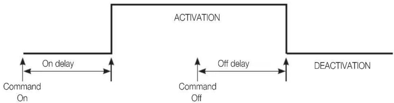
flowchart
graph LR
    A["Command On"] --> B["On delay"]
    B --> C["ACTIVATION"]
    C --> D["Command Off"]
    D --> E["DEACTIVATION"]
    style A fill:#f9f,stroke:#333
    style C fill:#ccf,stroke:#333
    style E fill:#cfc,stroke:#333
- Behaviour of one-position stable actuator for POWER DOWN/UP

flowchart
graph TD
    A["On delay=0"] --> B["ACTIVATION"]
    B --> C["Command On"]
    B --> D["Power down"]
    B --> E["DEACTIVATION"]
    E --> F["Power up"]
    style A fill:#f9f,stroke:#333
    style B fill:#ccf,stroke:#333
    style C fill:#cfc,stroke:#333
    style D fill:#fcc,stroke:#333
    style E fill:#cff,stroke:#333
    style F fill:#ffc,stroke:#333
Appendix
- Behaviour of two-position stable actuator for POWER DOWN/UP
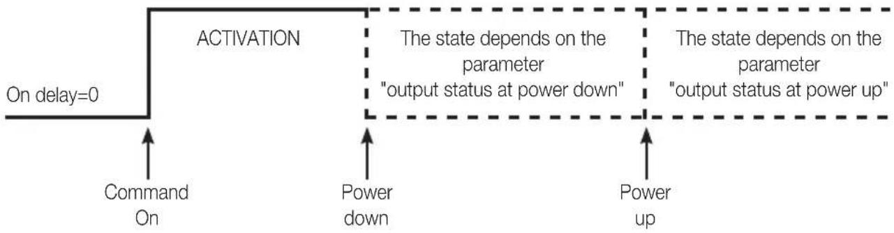
flowchart
graph TD
    A["On delay=0"] --> B["ACTIVATION"]
    B --> C["Command On"]
    B --> D["Power down"]
    B --> E["Power up"]
    C --> F["The state depends on the parameter "output status at power down""]
    D --> G["The state depends on the parameter "output status at power up""]
    E --> H["Power up"]
ROLLER SHUTTER ACTUATOR
- Request to raise the roller shutter and later on a request to lower it.

flowchart
graph LR
    A["UP request"] --> B["UP ROLLER SHUTTER"]
    B --> C["DOWN request"]
    D["Down time"] --> E["DOWN ROLLER SHUTTER"]
    E --> F["Down request"]
    style A fill:#f9f,stroke:#333
    style B fill:#ccf,stroke:#333
    style C fill:#cfc,stroke:#333
    style D fill:#fcc,stroke:#333
    style E fill:#cff,stroke:#333
- Request to raise the roller shutter and later on a request to lower it while it is raising. The "command execution delay" parameter is set to a value other than 0.

flowchart
graph LR
    A["UP ROLLER SHUTTER"] --> B["Up time"]
    B --> C["Interlock 500 ms"]
    C --> D["Down time"]
    D --> E["DOWN ROLLER SHUTTER"]
    F["Request UP"] --> G["Command execution delay >0"]
    H["Request DOWN"] --> I["Command execution delay >0"]
Appendix
- Request for positioning the roller shutter at a certain value (this case is similar also in the case of calling up a scene).

flowchart
graph LR
    A["Roller shutter height request"] --> B["ROLLER SHUTTER POSITIONING"]
    B --> C["Interlock 500 ms"]
    C --> D["RESET SLAT ANGLE"]
- Behaviour of the actuator in the event of close slat rotation requests (the "command execution delay" parameter is always null for the slats).

flowchart
graph TD
    A["SLAT"] --> B["ROTATION SLAT"]
    B --> C["Interlock 500 ms"]
    C --> D["ROTATION SLAT"]
    D --> E["SLAT rotation request"]
    D --> F["New slat rotation request"]
    style A fill:#f9f,stroke:#333
    style D fill:#f9f,stroke:#333
    note1["Rotation time/10"] --> A
    note2["Rotation time/10"] --> B
    note3["Interlock 500 ms"] --> C
- Request for forcing during the movement of the roller shutter

flowchart
graph TD
    A["Up time"] --> B["Roller Shutter UP"]
    B --> C["Interlock 500 ms"]
    C --> D["Request UP"]
    D --> E["Request for FORCING (managed at the end of the interlock)"]
    style A fill:#f9f,stroke:#333
    style B fill:#ccf,stroke:#333
    style C fill:#cfc,stroke:#333
    style D fill:#fcc,stroke:#333
    style E fill:#cff,stroke:#333
    note right of C: THE BEHAVIOUR OF THE ROLLER SHUTTER DEPENDS ON THE PARAMETER "POSITION ON FORCING"
    note right of C: THE BEHAVIOUR OF THE ROLLER SHUTTER DEPENDS ON THE PARAMETER "POSITION ON FORCING"
Appendix
- Request for scene saving during the movement of the roller shutter

flowchart
graph TD
    A["Request UP"] --> B["Roller Shutter UP"]
    C["Scene saving request"] --> B
    D["The scene is saved with roller shutter fully open"] --> B
- Request for forcing during the interlock period

flowchart
graph TD
    A["UP ROLLER SHUTTER"] --> B["Interlock 500 ms"]
    B --> C["Down ROLLER SHUTTER"]
    C --> D["Interlock 500 ms"]
    D --> E["The Behaviour of the ROLLER SHUTTER DEPENDS ON THE PARAMETER "POSITION ON FORCING""]
    F["Request UP"] --> A
    G["Request DOWN"] --> C
    H["Request for FORCING (managed at the end of the interlock)"] --> C
- Setting an absolute value for slat rotation during the movement of the roller shutters

flowchart
graph TD
    A["Request UP"] --> B["Roller Shutter UP"]
    B --> C["Slat rotation request at a certain value (the message is ignored)"]
    style A fill:#f9f,stroke:#333
    style B fill:#ccf,stroke:#333
    style C fill:#cfc,stroke:#333
WARNING.
To read the FAQs for the By-me system, please see our website www.vimar.com under the section Support --> FAQ.


- Section
- Automation
- Table of Contents
- General information....6
- General information
- Main functions:
- Main functions.
- Basic concepts
- Basic concepts.
- IMPORTANT:
- Installation topology
- Installation topology.
- WARNING:
- Bus system installation.
- General rules and system topology.
- System setup.
- Bus length: general rules.
- Length of the BUS line.
- Bus installation: summary table.
- • Installation and system topology:
- • Devices and distances per line
- Terminals of the control unit.
- Putting the system into service.
- Main configurations
- Main configurations.
- Navigating through the control unit menus.
- Initial switch-on.
- Control unit main screen.
- Settings menu.
- Setting the clock.
- Language settings.
- Display and Tones.
- User Management.
- Creating a new User
- Administrator
- Events Prog. User
- Guest
- Generic user
- Favourite Application.
- Screen saver.
- Temperature Probe
- - Calibration.
- Use
- Main Menu → Temperature Probe
- Temperature Unit
- Configuration menu.
- Creating a new functional group.
- Creating a new group.
- Functional unit selection and configuration.
- Example 1.
- Functional unit selection.
- Example 2.
- Rules for creating groups.
- Note on built-in controls.
- Add devices to a functional group.
- N.B.
- Remove a functional unit from a functional group.
- Modifying device parameters.
- Changing the name of a group.
- Removing a group.
- Device identification.
- Device reset.
- Control unit reset.
- Device parameters.
- - Functional unit – Left push button
- - Functional unit - Middle button (only for single buttons with 3 modules)
- - Functional unit – Right push button
- - Functional unit – Left rocker switch
- - Functional unit - Middle rocker switch (only for rocker switches with 3 modules)
- - Functional unit – Right rocker switch
- • Functional unit - Relay
- • Functional unit - dimmer
- - Command 10 V -
- - Contact interface with 2 inputs
- • Interface for traditional controls
- - Roller shutter actuator
- - Actuator for roller shutters and blinds (01852.2):
- • Infrared remote control receiver
- - IR detector, with dual technology and wall-mounting, mini)
- Configuration of Actuator with 4 relay outputs 01471
- ACTUATOR
- ROLLER SHUTTER ACTUATOR
- FANCOIL
- Functional blocks
- Selecting the functional block to be configured:
- Scenes.
- Description of the parameters
- ACTUATOR AND TIMER CONTROLLED ACTUATOR
- ROLLER SHUTTER AND BLINDS ACTUATOR
- Installing and configuring the touch screens
- - Resetting the touchscreen
- Installation and configuration of the By-me module 01965.
- Router Control
- Communicator interface management.
- USB Interface Management 01847
- Configuration of logic unit 01468
- Updating the logic unit firmware.
- Web Server management
- - Configuration of the Web Server.
- • Authentication of the Web Server.
- - Removing the Web Server.
- Managing BUS interface with EnOcean module
- - Operation
- - Interface configuration.
- - Removing devices
- - Changing interface parameters
- Interface for managing emergency lamps via By-me BUS 01846.
- Technical characteristics
- Configuration.
- Parameters.
- Scenarios.
- Scenarios
- Scenarios.
- Creating a scenario.
- Example.
- Activating a scenario.
- Activating with the control unit.
- Activation with button control.
- Note.
- Activation with touchscreen control.
- Renaming a scenario.
- Cancelling a button associated with the scenario
- Modifying groups associated with a scenario.
- Saving a scenario.
- Remote activation of a scenario.
- Deleting a scenario.
- Programming events
- Programming events
- Programming.
- Creating a program.
- Inputs.
- Logic elements.
- Input Logic Elements.
- Outputs.
- Logic elements.
- Timing.
- - Cyclic clock
- - Timer.
- - None.
- Renaming a program.
- Editing a program.
- Deleting a program.
- Operation.
- Application Examples.
- Switch on outside lights in the evening.
- - Desired program:
- Warning!
- Daily watering.
- • Weekly clock timing: a timer program is used for the required days.
- - Inputs:
- - Outputs:
- Roller shutter automation.
- Load management by time slots.
- Integration of the presence detectors
- Integration of the presence detectors.
- Diagnostics and maintenance
- Diagnostics and maintenance.
- Diagnostics and replacement of devices.
- Setup → Diagnostics → Device diagnostics
- IMPORTANT
- Remote communications management.
- Remote control.
- Information on the control unit and system.
- Installation rules - Compliance with regulations
- Installation rules.
- Regulatory compliance.
- WEEE - Information for users
- Supplementary declarations made by the manufacturer.
- Home automation control equipment
- Index
- Presentation of the system
- General features
- Devices and functions
- Devices and functions
- Configuration on the control unit
- Configuration on the control unit
- Functional unit selection and configuration.
- Devices and their functional units
- PUSHBUTTON
- ROCKER SWITCH
- Configuration of art 01480 and 01485
- FUNCTIONAL UNITS
- Selecting the functional unit to be configured:
- Configuration of art 01481 and 01486
- Configuration of art 01482 and 01487
- Setting/changing the parameters.
- Functional units and their parameters
- PUSHBUTTON AND ROCKER SWITCH
- Speaker system
- General characteristics of the system.... 95
- Devices and functions 96
- Topology and installation rules 99
- System constraints.... 101
- Functionality 107
- System components.... 110
- Group/zone definition.... 132
- Types of system 144
- Glossary.... 153
- General characteristics of the system
- Transmitter devices
- Receiver devices
- Acoustic speakers
- Accessory modules
- Topology and installation rules
- Topologies and installation rules
- Installation topologies
- System constraints
- Installation rules
- System constraints
- Distances
- Absorption of the devices and sizing of the system
- Number of devices
- Functionality
- Functionality
- Control buttons
- Zone priority
- Microphone call
- Baby control function
- Audio monitoring function
- Alarm clock function
- Timed shutdown function (Sleep)
- Silencing function
- Voice communications function
- Scenarios
- System components
- System components
- Control unit.
- Control unit main screen.
- Audio input with 2 RCA connectors, automatic adjustment of the input sensitivity, integrated line terminator.
- It is supplied in the following versions:
- Indicators
- Operation
- Settings which can be configured directly from the device
- Settings that can be configured via the control unit
- Device reset
- FM radio tuner with RDS, coaxial connector for external FM aerial, integrated line terminator, installation on DIN rail (60715 TH35), occupies 2 modules of 17.5 mm.
- N.B. If the radio function is included in the scenarios, together with the groups of the receivers also the radio module must be added so as to save the station to call up.
- Home automation control module with four pushbuttons, RGB LED location in the dark with brightness control, to be completed with interchangeable half-buttons: 1 or 2 module Eikon, 2 module Arké or Plana.
- Common technical specifications
- Characteristics art. 01483
- Characteristics art. 01484
- Configuration
- Parameters
- Docking station for iPod and iPhone devices, supplied with power supply - 2 modules. (The article is composed of 2 appliances of 2 modules each, can be installed also separately)
- Bluetooth® technology interface for home automation.
- Configuration button
- Settings that can be configured from the control unit
- Microphone for selective or general call, voice activation function to control the children (Baby Control) and for audio monitoring - 2 modules
- - "Push To Talk" general call.
- - "Push To Talk" selective call.
- • "Baby Control" service.
- • Audio Monitoring.
- Resetting:
- Interface for transmitting By-me commands to IR receiver, together with 3 m cable.
- Modifying an action
- Other parameters
- Decoupler for Bus line / speaker system for By-me power supply, integrated line terminator, installation on DIN rail (60715 TH35), occupies 2 modules of 17.5 mm.
- Tap-off for By-me command devices, flush mounting (retrofit).
- Branch tap-off for speaker system devices, flush mounting (retrofit)
- Group/zone definition
- Group/zone definition
- Managing audio groups
- Creating a group
- Removing a group
- Managing audio zones
- Creating an audio zone
- Removing an audio zone
- Audio zone settings
- ■ Priority
- ■ Audio sources
- ■ Max volume [%]
- ■ Max switch-on volume [%]
- ■ Call volume [%]
- ■ Max silencing volume [%]
- ■ General switch-on
- ■ Selective switch-on
- Alarm clock function
- Viewing the audio zones
- FM tuner control
- ■ Saving the radio stations
- Bluetooth technology interface control
- Managing the Docking Station
- Playback Menu
- Operation
- Docking Station Database Navigation Menu
- Operation
- Details menu of the RCA source associated with the IR interface 20586-19586-14586
- Adding devices to a group
- Removing devices from a group
- Modifying device parameters
- Device parameters
- ■ Functional unit – RCA Audio Input
- ■ Functional unit - FM tuner
- ■ Functional unit – Microphone/Call
- ■ Functional unit – Rocker switch for Audio control
- ■ Functional unit – Rocker switch for Audio Monitoring
- ■ Functional unit - IR stereo control
- ■ Functional unit – Dock. iPod/iPhone Station
- ■ Functional unit - Bluetooth module
- Types of system
- Types of system
- Audio zones with receiver modules and By-me controls
- Audio zones with voice call function
- Audio zones with Baby Control function
- Audio zones with audio monitoring function
- Audio zones with voice communication function
- Audio zones with central switch-off
- Bluetooth technology interface connected to the speaker system bus
- Bluetooth technology interface connected to the speaker system bus and third-party amplifier
- Glossary
- Glossary
- Source
- Transmission channel
- Transmitter (TX)
- Receiver (RX)
- Group
- Zone
- Track
- Light Control
- Configuration on the controller
- Configuration on the controller
- Device parameters
- Setting/changing the parameters of the dimmers.
- WHITE dimmers
- Speed of adjustment
- Minimum adjustment value
- Ramp Operation
- Delayed switch-off with warning function
- Time for changing absolute brightness.
- Phase cutting
- Flash Start
- RGB dimmers
- - Possible controls
- - Operating parameters
- Related adjustments
- Fading-show
- Parameters:
- Application examples
- Application examples
- • Example 1
- - Example 2
- Power management
- General characteristics
- Load control
- Load control
- Configuration of the load control module 01455
- ■ Single-phase system with no generation
- ■ Single-phase system with "local" generation
- ■ Single-phase system with “remote” generation
- ■ Three-phase system with no generation
- ■ Three-phase system with generation (from one to three phases)
- Installing the sensors
- Physical installation of the sensors
- Setting the sensors on devices art. 01455 and 01450
- Setting the trigger thresholds
- ■ Single-phase system
- ■ Three-phase system
- Creating control groups
- Priority settings.
- CAUTION!
- Displaying the level of power consumed.
- Configuring a load cut-out signalling relay
- Programming by time slots
- Load operation control.
- Measurement control
- • POWER METER art. 01450
- • ACTUATOR WITH CURRENT SENSOR art. 01456, 20537-19537-14537
- - POWER METER WITH BUILT-IN CURRENT SENSOR art. 01451
- • PULSE COUNTER INTERFACE art. 01452
- Power management → Measurement control
- Alarm control
- Device parameters
- Tactil Devices
- System Features - Devices and Functions
- General system characteristics
- Functional units of devices
- Functional unit selection for configuration.
- Description of parameters.
- PUSH BUTTON AND ROCKER BUTTON
- RGB LED
- Temperature control
- Functional unit selection and configuration.... 207
- Configuration of the climate controller for heating systems 01465
- Configuration of the Main functional unit
- Configuring the External Temperature functional unit
- Configuring the Auxiliary Temperature functional unit (T3)
- Configuring the Humidity functional unit
- Note on automatic programmes:
- Configuration of proportional analogue 4-output actuator 01466
- Configuration of device with 3 analogue signal inputs 01467
- Example:
- Confirm → Yes
- N.B.:
- Configuration of thermostat 02951
- Configuration of temperature probe 20538-19538-14538
- Configuration of IR interface 20584.1-19584.1-14584.1
- Pair actions with the actual command.
- Setting/changing the parameters.
- • CLIMATE CONTROLLER FOR HEATING SYSTEMS 01465
- Main functional unit and Circulation pump
- External Temperature and Auxiliary Temperature
- Humidity Functional unit
- Types of alarm and climate controller actions
- • ACTUATOR WITH 4 PROPORTIONAL ANALOGUE OUTPUTS 01466
- • DEVICE WITH 3 ANALOGUE SIGNAL INPUTS 01467
- Functional unit input 0-10 V or 4-20 mA
- Functional unit input for NTC temperature sensor
- Functional unit input for brightness adjustment sensor
- • THERMOSTAT 02951
- Functional unit thermostat
- Functional unit output
- • TEMPERATURE PROBE 20538-19538-14538
- Test procedure for the climate controller 01465
- Air-conditioning control.
- Operating modes.
- Touch screen thermostat 02951 and temperature probe 20538-19538-14538
- Climate controller for heating systems (art. 01465)
- Setting the speed of the fan coils
- Forced switch-off.
- Programming.
- Setting the automatic program
- Setting temperature levels.
- Example of installation
- Example of installation
- ■ RADIATORS
- ■ 2 PIPE FLOOR HEATING
- ■ RADIATORS + AIRCON
- ■ PROPORTIONAL RADIATORS + AIR-CON (VIA SPLIT IR)
- ■ PROPORTIONAL RADIATORS + AIR-CON
- ■ SYSTEM WITH 2 FANCOIL PIPES
- ■ SYSTEM WITH 2 PIPE FANCOIL + RADIATORS
- ■ SYSTEM WITH 4 PIPE FANCOIL
- ■ SYSTEM WITH 4-PIPE FANCOIL + 4 FLOOR HEATING PIPES (HEATING + COOLING)
- ■ SYSTEM WITH 4 PIPE FANCOIL + FLOOR HEATING
- ■ AIRCON WITH HEAT PUMP (VIA THE SAME SPLIT IR DEVICE)
- ■ INTEGRATION METHODS
- ■ SYSTEM WITH CLIMATE CONTROLLER IN FIXED MODE
- ■ SYSTEM WITH CLIMATE CONTROLLER IN MODULATING MODE
- Climate control using the thermostats Idea 16953-16954
- Climate control using the thermostats Idea 16953-16954.
- Zone management
- Creating an HVAC group.
- Creating an HVAC zone
- Associating an HVAC group to a zone already configured
- Zone activation.
- Removing a zone
- Zone Settings
- Heating or air-conditioning mode.
- Temperature differential.
- Normal or protected operation.
- Range of protection
- Type of system.
- SYSTEM WITH 2 PIPES - 1 ZONE
- TECHNICAL ROOM.
- Relay actuator operating mode for a 2-pipe system.
- Relay actuator operating mode for a 4-pipe system.
- Select temperature zone to be displayed.
- Operating modes.
- Setting the speed of the fan coils
- Forced switch-off.
- Programming.
- Plug&Play Home Automation System
- Functional block selection and configuration.
- Devices and their functional blocks
- PUSH-BUTTON
- ROCKER BUTTON
- Configuration of Module with 9 inputs and 8 outputs 01470
- Configuration of Module with 3 digital inputs and 3 outputs to control LED 01475
- Configuration of Module with 2 digital inputs, 1 roller shutter output and 2 outputs to control LED 01476
- Configuration of Module with 2 digital inputs, 1 relay output and 2 outputs to control LED 01477
- Functional blocks and their parameters
- PUSH-BUTTON AND ROCKER BUTTON
- CIRCULATION PUMP
- Configuration of controls and actuators on multiple groups
- SIMPLE GROUP
- GROUP DEPTH ON THE ACTUATORS
- GROUP DEPTH ON THE COMMAND
- Appendix
- APPENDIX - Operation of actuators for art. 01470, 01471, 01476, 01477
- RELAY ACTUATOR
- WARNING.
Brand : Vimar
Model : R21509
Category : Home Automation