
M20.04 - Loudspeaker MARTIN - Free user manual and instructions
Find the device manual for free M20.04 MARTIN in PDF.


| Product Type | Passive Loudspeaker |
| Brand | Martin |
| Model | M20.04 |
| Dimensions (H x W x D) | 300 mm x 200 mm x 250 mm |
| Weight | 5.2 kg |
| Impedance | 8 ohms |
| Power Handling (RMS) | 100 W |
| Peak Power Handling | 200 W |
| Frequency Response | 60 Hz - 20 kHz |
| Sensitivity | 89 dB |
| Driver Configuration | 1 x 4" woofer, 1 x 1" tweeter |
| Enclosure Type | Bass reflex |
| Input Connectors | 2 x Speakon NL4MP |
| Recommended Amplifier Power | 50 - 150 W RMS |
| Material | Birch plywood with black textured finish |
| Operating Temperature | 0°C to 40°C |
| Cleaning Instructions | Wipe with a dry, soft cloth. Do not use solvents. |
| Safety Precautions | Do not expose to rain or moisture. Ensure stable placement. |
| Spare Parts Availability | Contact Martin authorized service centers for replacement drivers. |
| Repairability | Repairable by qualified personnel. Use only original parts. |
Frequently Asked Questions - M20.04 MARTIN
User questions about M20.04 MARTIN
0 question about this device. Answer the ones you know or ask your own.
Ask a new question about this device
Download the instructions for your Loudspeaker in PDF format for free! Find your manual M20.04 - MARTIN and take your electronic device back in hand. On this page are published all the documents necessary for the use of your device. M20.04 by MARTIN.
USER MANUAL M20.04 MARTIN
IMPORTANT SAFETY INSTRUCTIONS

The lightning flash with an arrowhead symbol within an equilateral triangle, is intended to alert the user to the presence of uninsulated "dangerous voltage" within the product's enclosure that may be of sufficient magnitude to constitute a risk of electric shock to persons.

The exclamation point within an equilateral triangle is intended to alert the user to the presence of important operating and maintenance (servicing)
instructions in the literature accompanying the product.
1 Read these instructions.
2 Keep these instructions.
3 Heed all warnings.
4 Follow all instructions.
5 Do not use this apparatus near water.
6 Clean only with dry cloth.
7 Do not block any ventilation openings. Install in accordance with the manufacturer's instructions.
8 Do not install near any heat sources such as radiators, heat registers, stoves, or other apparatus (including amplifiers) that produce heat.
9 Do not defeat the safety purpose of the polarized or grounding-type plug. A polarized plug has two blades with one wider than the other. A grounding type plug has two blades and a third grounding prong. The wide blade or the third prong are provided for your safety. If the provided plug does not fit into your outlet, consult an electrician for replacement of the obsolete outlet.
10 Protect the power cord from being walked on or pinched particularly at plugs, convenience receptacles, and the point where they exit from the apparatus.
11 Only use attachments/accessories specified by the manufacturer.
12 Use only with the cart, stand, tripod, bracket, or table specified by the manufacturer, or sold with the apparatus. When a cart is used, use caution when moving the cart/apparatus combination to avoid injury from tip-over.
13 Unplug this apparatus during lightning storms or when unused for long periods of time.
14 Refer all servicing to qualified service personnel. Servicing is required when the apparatus has been damaged in any way, such as power-supply cord or plug is damaged, liquid has been spilled or objects have fallen into the apparatus, the apparatus has been exposed to rain or moisture, does not operate normally, or has been dropped.
Warning!
- To reduce the risk of fire or electrical shock, do not expose this equipment to dripping or splashing and ensure that no objects filled with liquids, such as vases, are placed on the equipment.
• This apparatus must be earthed. - Use a three wire grounding type line cord like the one supplied with the product.
- Be advised that different operating voltages require the use of different types of line cord and attachment plugs.
- Check the voltage in your area and use the correct type. See table below:
| Voltage Line plug according to standard |
| 110-125V UL817 and CSA C22.2 no 42. |
| 220-230V CEE 7 page VII, SR section107-2-D1/IEC 83 page C4. |
| 240V BS 1363 of 1984.Specification for 13A fused plugs and switched and unswitched socket outlets. |
- This equipment should be installed near the socket outlet and disconnection of the device should be easily accessible.
- To completely disconnect from AC mains, disconnect the power supply cord from the AC receptable.
- The mains plug of the power supply shall remain readily operable.
- Do not install in a confined space.
- Do not open the unit - risk of electric shock inside.
Caution:
You are cautioned that any change or modifications not expressly approved in this manual could void your authority to operate this equipment.
Service
- There are no user-serviceable parts inside.
- All service must be performed by qualified personnel.
IMPORTANT SAFETY INSTRUCTIONS
EMC / EMI.
This equipment has been tested and found to comply with the limits for a Class B Digital device, pursuant to part 15 of the FCC rules. These limits are designed to provide reasonable protection against harmful interference in residential installations. This equipment generates, uses and can radiate radio frequency energy and, if not installed and used in accordance with the instructions, may cause harmful interference to radio communications. However, there is no guarantee that interference will not occur in a particular installation. If this equipment does cause harmful interference to radio or television reception, which can be determined by turning the equipment off and on, the user is encouraged to try to correct the interference by one or more of the following measures:
- Reorient or relocate the receiving antenna.
- Increase the separation between the equipment and receiver.
- Connect the equipment into an outlet on a circuit different from that to which the receiver is connected.
- Consult the dealer or an experienced radio/TV technician for help.
For the customers in Canada:
This Class B digital apparatus complies with Canadian ICES-003.
Certificate Of Conformity
MACH SPEAKERS A/S, Perspektivvej 2, DK-9900 Frederikshavn, Denmark - hereby declares on own responsibility that following products:
Loudspeaker Management Controller
- that is covered by this certificate and marked with CE-label conforms with following standards:
EN 60065 Safety requirements for mains (IEC 60065) operated electronic and related apparatus for household and similar general use
EN 55103-1 Product family standard for audio, video, audio-visual and entertainment lighting control apparatus for professional use. Part 1: Emission.
EN 55103-2 Product family standard for audio, video, audio-visual and entertainment lighting control apparatus for professional use. Part 2: Immunity.
With reference to regulations in following directives:
73/23/EEC, 89/336/EEC
December 2004
Michael Holmbo
- Mach Speakers A/S
TABLE OF CONTENTS
INTRODUCTION
Important Safety Instructions &
Certificate of conformity .....a-b
Table of Contents 3
Introduction 4
Front Panel Overview 6
Rear Panel Overview 8
Signal Flow Diagram .....9
Typical Setups 10
OPERATION
Control Section .....15
Editing Parameters .....15
Recall 15
Store 15
The Setup Menu .....15
The Lock mode .....15
Front Panel Operation .....16
APPENDIX
Technical Specifications .....19
Thank you for purchasing the Mach M20.04 digital system controller from Mach Speakers A/S. Every effort has been made to ensure that our products meet your requirements and we sincerely hope that we will live up to your expectations.
The Mach M20.04 has been designed for superior audio quality and flexible system configuration and is intended to optimize the performance of Mach loudspeaker systems.
The Mach M20.04 is a compact and powerful DSP-based audio-processing unit capable of operating the speakers in the Mach product range that require or benefit from the use of a system controller. It is ideal for fixed installations and live applications as it combines the functions of multiple conventional products in a compact 1 U of rack space.
The Mach M20.04 has two balanced XLR analog Inputs, a digital Input at 44.1 or 48 kHz, and four balanced XLR analogue outputs. It is supplied pre-loaded with the most common configurations of our product range. Furthermore, 100 "user presets" are available for other loudspeaker combinations, which may be required for certain applications.
This manual contains technical specifications and describes how to configure the Mach M20.04 to suit your specific application and achieve the best possible performance from the unit.
The MACH M20.04 incorporates the following fully configurable features:
• Each Input has gain control and 4 bands of Parametric EQ. Bands 1 & 4 can be set for LF & HF shelving response.
- Routing section - The signals present on Inputs A & B can be routed to any of the four Output channels
- Crossovers on each Output channel - Variable high and low pass filters for each output can be set with a choice of classic filters. Independent control over high pass and low pass functions allow asymmetric crossover functions to be used.
- Four band parametric EQ on each Output
- Four independent Delay lines (up to 200ms)
- Four high performance Limiters, featuring a wide range of control over Attack, Release & Threshold parameters.
- Output Gain adjustment
FRONT PANEL OVERVIEW

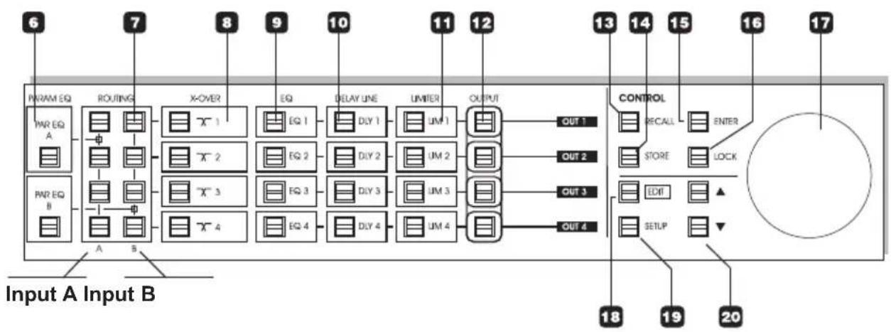
1 POWER On/Off
The MACH M20.04 uses a switchmode power-supply that accepts from 100-240V AC.
2 INPUT METERS
For optimal performance the Input level indication should be around -5dB and occasionally peak at 0dB. If the CLIP indicator is lit the Input signal is too hot. Input sensitivity can be set in the Level menus accessed via the INPUT A/B keys, or via the Setup menu.
3 DISPLAY
32 character LCD displaying various operating parameters.
4 DIGITAL IN select
Press the DIGITAL IN key and the MACH M20.04 will try to lock to the Digital Input. If a valid digital clock is present on the Input the unit will automatically use the digital signal as Input source. Press once more to release and switch to analog Inputs.
5 INPUT A/B
On/Off switches for the two channels. For the signal to pass further down the signal chain the key LEDs must be lit.
In Edit mode these switches give access to the Input Trim parameter for each channel.
6 PAR EQ A/B
On/Off switches for the Parametric EQ on channel A and B. In Edit mode these keys give access to edit EQ settings.
7 ROUTING matrix
The Output Routing Matrix allows you to freely distribute Input channels A/B to any of the four Output channels.
Use the four switches in column A to send the signal from Input channel A to any of the four Outputs.
Use the four switches in column B to send the signal from Input channel B to any of the four Outputs.
8 X-OVER keys
On/Off switches for the X-Overs.
In Edit mode these keys give access to edit X-Over settings.
9 EQ
On/Off switches for the EQ section on the four Output channels.
In Edit mode these keys give access to edit the EQ parameters.
10 DELAY LINE
On/Off keys for the Delay block on the four Output channels.
In Edit mode these keys give access to edit the Delay parameters.
11 LIMITER
On/Off keys for the Limiter block on the four Output channels.
In Edit mode these keys give access to edit the Limiter parameters.
FRONT PANEL OVERVIEW
flowchart
graph LR
    A["PARAM EQ"] --> B["ROUTING"]
    B --> C["X-OVER"]
    C --> D["EQ"]
    D --> E["DELAY LINE"]
    E --> F["UMITER"]
    F --> G["OUTPUT"]
    G --> H["CONTROL"]
    H --> I["RECALL"]
    I --> J["ENTER"]
    J --> K["STORE"]
    K --> L["LOCK"]
    L --> M["EDIT"]
    M --> N["SETUP"]
    N --> O["18"]
    N --> P["19"]
    N --> Q["20"]
    R["PWR EQ A"] --> S["A"]
    T["PWR EQ B"] --> U["B"]
    V["Input A Input B"] --> W["Control Block"]
    style A fill:#f9f,stroke:#333
    style B fill:#ccf,stroke:#333
    style C fill:#cfc,stroke:#333
    style D fill:#fcc,stroke:#333
    style E fill:#cff,stroke:#333
    style F fill:#ffc,stroke:#333
    style G fill:#fcf,stroke:#333
    style H fill:#cff,stroke:#333
    style I fill:#ffc,stroke:#333
    style J fill:#cfc,stroke:#333
    style K fill:#fcc,stroke:#333
    style L fill:#ffc,stroke:#333
    style M fill:#cfc,stroke:#333
    style N fill:#fcc,stroke:#333
    style O fill:#ffc,stroke:#333
    style P fill:#cfc,stroke:#333
    style Q fill:#fcc,stroke:#333
12 OUTPUT
On/Off keys on the Output for each of the four channels.
In Edit mode these keys give access to edit the Output level parameter.
13 RECALL
In Recall mode you select which preset to recall using the ADJUST encoder and press ENTER to confirm.
14 STORE
Press to STORE. Select a storing location using the ADJUST wheel and press ENTER to confirm.
15 ENTER
The ENTER key is used to confirm various operations such as Store and Recall.
16 LOCK
The LOCK key is used to lock/unlock the MACH M20.04 front panel keys. Default setting is "locked".
17 ADJUST encoder
The ADJUST Encoder is used to change values on various parameters - especially in the Edit mode.
18 EDIT
Press to enter Edit mode and select which parameter to edit by pressing the parameter keys.
19 SETUP
Press to enter the Setup menu. In the Setup menu you will find parameters such as Lock setup, various Level settings and Display Viewing.
20 CURSOR keys
Use the CURSOR keys to scroll between parameters in the various menus.
REAR PANEL

Balanced Inputs on XLR for channels A/B. Use channel A for mono Input. Balanced Outputs 1-4 on XLR. Digital S/PDIF In and Thru on RCA phono. Com port for data transfer. NO user application. Power Input. The internal switchmode powersupply accepts from 100 to 240 VAC.
flowchart
graph LR
    A["ANALOG INPUTS [balanced"]] -->|A| B["A/D"]
    C["ANALOG IN LEVEL"] -->|B| B
    B --> D["Digital/Analog Input Selector"]
    D --> E["Input PPM"]
    E --> F["IN A"]
    E --> G["IN B"]
    F --> H["PARAM EQ A"]
    G --> I["PARAM EQ B"]
    H --> J["ROUTING"]
    I --> J
    J --> K["Processing"]
    K --> L["EQ"]
    K --> M["EQ"]
    K --> N["EQ"]
    L --> O["DELAY"]
    M --> P["DELAY"]
    N --> Q["DELAY"]
    O --> R["LIMITER"]
    P --> S["LIMITER"]
    Q --> T["LIMITER"]
    R --> U["OUT"]
    S --> V["OUT"]
    T --> W["OUT"]
    U --> X["D/A"]
    V --> X
    W --> X
    X --> Y["ANALOG OUTPUTS [balanced"]]
    Y --> Z["1"]
    Y --> AA["2"]
    Y --> AB["3"]
    Y --> AC["4"]
    Z --> AD["Digital Output [S/PDIF"]]
    AA --> AD
    AB --> AD
    AC --> AD
TYPICAL SETUPS
Stereo Setup - with subs

flowchart
graph TD
    A["Input Source A/B"] --> B["Full Range Loudspeaker"]
    B --> C["Full Range Loudspeaker"]
    C --> D["Subwoofer"]
    D --> E["Subwoofer"]
    E --> F["Amp"]
    F --> G["Out 1"]
    F --> H["Out 2"]
    F --> I["Out 3"]
    F --> J["Out 4"]
    F --> K["Amp"]
This is a typical stereo setup with a set of subs.
Analog:
- Input signal is fed on Inputs A/B.
- Configure Routing section as illustrated below.
- Output channels 1 and 2 feed the front loudspeakers.
- Output channels 3 and 4 feed the subs.
Configuration overview

Using the Digital Input
- Digital Input 44.1 or 48kHz must be present in the Digital Input.
- Press and hold the DIGITAL IN button on the front panel until digital lock is achieved.
Note: The signal present on the DIGITAL INPUT is passed unprocessed to the DIGITAL THRU connection on the rear panel for further downstream processing.
TYPICAL SETUPS
Stereo Setup

flowchart
graph TD
    A["Input Source A/B"] --> B["Switch"]
    B --> C["Amplifier"]
    C --> D["Output 1"]
    C --> E["Output 2"]
    C --> F["Output 3"]
    C --> G["Output 4"]
    H["From I/p A From I/p A"] --> C
    I["From I/p B From I/p B"] --> J["Switch"]
    J --> K["Amplifier"]
    K --> L["Output 1"]
    K --> M["Output 2"]
    K --> N["Output 3"]
    K --> O["Output 4"]
This setup is a typical small 2-way system.
Analog
- Input signal is fed to Inputs A and B.
- Configure Routing section as illustrated below.
- Output channels 1 and 2 feed loudspeaker set A.
- Output channels 3 and 4 feed loudspeaker set B.
Configuration overview

Using the Digital Input
• Digital Input 44.1 or 48kHz must be present in the Digital Input.
- Press and hold the DIGITAL IN button on the front panel until digital lock is achieved.
Note: The signal present on the DIGITAL INPUT is passed unprocessed to the DIGITAL THRU connection on the rear panel for further downstream processing.
3/4 way setup - Bi-Amp Mid/High

flowchart
graph TD
    A["Input A"] --> B["Bi-amped Loudspeaker"]
    B --> C["Amp"]
    C --> D["Amp"]
    D --> E["Subwoofer"]
    E --> F["Subwoofer"]
    G["Input A"] --> H["Bi-amped Loudspeaker"]
    H --> I["Amp"]
    I --> J["Amp"]
    J --> K["Subwoofer"]
    K --> L["Subwoofer"]
    M["HF"] --> N["Out 1"]
    M --> O["Out 2"]
    M --> P["Out 3"]
    Q["MF"] --> R["Out 1"]
    Q --> S["Out 2"]
    Q --> T["Out 3"]
    U["HF"] --> V["Out 3"]
    W["MF"] --> X["Out 2"]
    Y["HF"] --> Z["Out 1"]
This example shows how 2 MACH M20.04s can be used in conjunction to distribute Input signals to a 3 or 4 way system per side.
For each side:
- Source signal can be connected to either Inputs A or B as only one Input per side is used. For this example - use Input A on both controllers.
- Configure the Routing section as illustrated below.
- Set Crossovers and additional parameters.
Configuration overview

flowchart
graph TD
    subgraph Left_Routing
        A1["Black Square"] --> A2["White Box"]
        A3["Black Square"] --> A4["White Box"]
        A5["Black Square"] --> A6["White Box"]
        A7["Black Square"] --> A8["White Box"]
        A9["Black Square"] --> A10["White Box"]
        A11["Black Square"] --> A12["White Box"]
        A13["Black Square"] --> A14["White Box"]
        A15["Black Square"] --> A16["White Box"]
        A17["Black Square"] --> A18["White Box"]
        A19["Black Square"] --> A20["White Box"]
    end
    subgraph Right_Routing
        B1["Black Square"] --> B2["White Box"]
        B3["Black Square"] --> B4["White Box"]
        B5["Black Square"] --> B6["White Box"]
        B7["Black Square"] --> B8["White Box"]
        B9["Black Square"] --> B10["White Box"]
        B11["Black Square"] --> B12["White Box"]
        B13["Black Square"] --> B14["White Box"]
        B15["Black Square"] --> B16["White Box"]
        B17["Black Square"] --> B18["White Box"]
        B19["Black Square"] --> B20["White Box"]
    end
    Left_Routing --> Right_Routing
    Left_Routing --> Right_Routing
Using the Digital Input
- Digital Input 44.1 or 48kHz must be present in the Digital Input.
- Press and hold the DIGITAL IN button on the front panel until digital lock is achieved.
Note: The signal present on the DIGITAL INPUT is passed unprocessed to the DIGITAL THRU connection on the rear panel for further downstream processing.
System Distribution - with delay

flowchart
graph TD
    A["Input A"] --> B["Device 1"]
    B --> C["Powered Speaker 1"]
    B --> D["Powered Speaker 2"]
    B --> E["Powered Speaker 3"]
    B --> F["Powered Speaker 4"]
    G["Input A"] --> H["Device 1"]
    H --> I["Powered Speaker 1"]
    H --> J["Powered Speaker 2"]
    H --> K["Powered Speaker 3"]
    H --> L["Powered Speaker 4"]
    M["Input A"] --> N["Device 1"]
    N --> O["Powered Speaker 1"]
    N --> P["Powered Speaker 2"]
    N --> Q["Powered Speaker 3"]
    N --> R["Powered Speaker 4"]
    S["Input A"] --> T["Device 1"]
    T --> U["Powered Speaker 1"]
    T --> V["Powered Speaker 2"]
    T --> W["Powered Speaker 3"]
    T --> X["Powered Speaker 4"]
    Y["Input A"] --> Z["Device 1"]
    Z --> AA["Powered Speaker 1"]
    Z --> AB["Powered Speaker 2"]
    Z --> AC["Powered Speaker 3"]
    Z --> AD["Powered Speaker 4"]
This example is similar to the previous example. However, the idea here is to distribute the signal with delay settings corresponding to the positioning of the speakers.
For each side:
- Source signal can be connected to either Inputs A or B as only one Input per side is used. For this example - use Input A on both controllers.
- Configure Routing section as illustrated in the configuration overview.
- Set a Delay time per channel matching the distance between the speakers.
- Set additional processing parameters.
Configuration overview

flowchart
graph TD
    subgraph_Left_Routing["Routing"]
        A1["Block 1"] --> B1["Block 2"]
        B1 --> C1["Block 3"]
        C1 --> D1["Block 4"]
        D1 --> E1["Block 5"]
        E1 --> F1["Block 6"]
        F1 --> G1["Block 7"]
        G1 --> H1["Block 8"]
    end
    subgraph_Right_Routing["Routing"]
        A2["Block 1"] --> B2["Block 2"]
        B2 --> C2["Block 3"]
        C2 --> D2["Block 4"]
        D2 --> E2["Block 5"]
        E2 --> F2["Block 6"]
        F2 --> G2["Block 7"]
        G2 --> H2["Block 8"]
    end
Using the Digital Input
- Digital Input 44.1 or 48kHz must be present in the Digital Input.
- Press and hold the DIGITAL IN button on the front panel until digital lock is achieved.
Note: The signal present on the DIGITAL INPUT is passed unprocessed to the DIGITAL THRU connection on the rear panel for further downstream processing.
Dual Source Mono - Dual Zone

flowchart
graph TD
    A["Loudspeaker Type A (Zone 1)"] -->|Source 1| B["Subwoofer Type A (Zone 1)"]
    B --> C["Out 1"]
    B --> D["Out 2"]
    B --> E["Out 3"]
    B --> F["Out 4"]
    G["Loudspeaker Type B (Zone 2)"] --> H["Subwoofer Type B (Zone 2)"]
    H --> I["Out 1"]
    H --> J["Out 2"]
    H --> K["Out 3"]
    H --> L["Out 4"]
    M["Amp"] --> N["Amp"]
    N --> O["Subwoofer Type B (Zone 2)"]
This setup is used where two different zones or rooms need to be covered. In this case Stereo is not the object.
- Source 1 is connected to Input A and Source 2 to Input B.
- Configure the Routing section as illustrated below.
- Set Crossovers and additional parameters.
Configuration overview

Using the Digital Input
• Digital Input 44.1 or 48kHz must be present in the Digital Input.
- Press and hold the DIGITAL IN button on the front panel until digital lock is achieved.
Note: The signal present on the DIGITAL INPUT is passed unprocessed to the DIGITAL THRU connection on the rear panel for further downstream processing.

Editing Parameters
Parameters in the Edit mode:
- Press EDIT followed by the key corresponding to the block you wish to edit.
- Use the CURSOR keys to select parameter and the ADJUST encoder to set the desired value.
Notice that the Lock function may be engaged and you will in that case not be able to edit parameters until it is disengaged. Please see the next column to learn about the Lock function.
Recall
To recall a preset
- Press RECALL
- Select preset using the ADJUST encoder
- Press ENTER

Reduce volume before recalling presets. Recalling a new preset may cause radical changes to both gain and routing settings.
Store
100 locations are available for user presets.
To store a preset
1 Press STORE
2 If the currently recalled preset is a User preset the same user location is suggested.
- If the currently recalled preset is a factory preset, the first free user location is suggested.
- If you wish to store the preset at a different location - select the desired user location using the ADJUST encoder.
3 Press ENTER.
4 Now you may;
- either press ENTER again to confirm and end the store operation
- or dial in a preset name of your choice using the CURSOR keys and ADJUST encoder and then press ENTER.
5 The display indicates "Preset Stored" for a successful store operation.
The Setup menu
The Setup menu holds various overall setup parameters.
Output Range
Range: 2, 8 (consum), 14, 20(pro) dBu. The Output range should match the Input sensitivity of your downstream device/amplifier. Please refer to the manual of that device.
Input Sensitivity
Range: 0 to 24dBu
The Input range should match the Output range of your feeding device. Please refer to the manual of that device or adjust according to the Input meters.
Delay Unit
The Delay time can be displayed in milliseconds, meters or feet.
Lock Function - introduction
As a speaker management controller is a key component in speaker setups a lock function is provided to prevent unintended change of parameters via the frontpanel.
Setting up the LOCK function is done via the Setup menu.
There are two basic Lock modes
- one mode where the frontpanel is unlocked simply by pressing the LOCK key once.
- another mode where you need to press LOCK and then dial in the “security code” followed by ENTER in order to unlock the function keys. The code is set via the Setup menu.
Timing function
A timing function can be set for both Lock modes allowing the front panel keys to be unlocked for either: 10, 30 or 60 seconds.
Range: Off, 10 seconds, 30 seconds, 60 seconds
Lock Code
Range: 0000-9999
"0000" is "no lock code" and the front panel keys can be locked/unlocked simply by using the LOCK key.
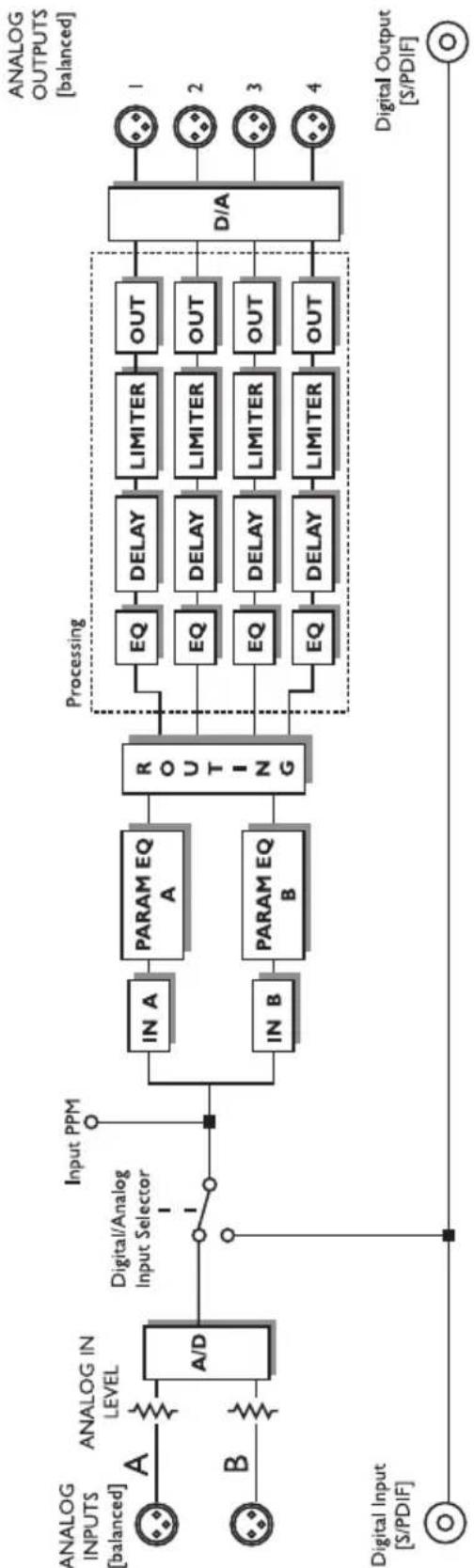
The following section takes a look at the processing chain following the front panel layout from left to right. On the front panel this is called the "Schematic Section"
Digital In

The MACH M20.04 accepts digital Input at 44.1 or 48kHz. Per default the MACH M20.04 is set to analog Inputs.
To switch to the digital Inputs.
- Be sure that a valid digital Input signal is present in the DIGITAL IN connection.
- Press the DIGITAL IN key. Analog Inputs are muted and the key LED will flash until lock is achieved.
• To return to Analog Inputs - press once more.
Input Bypass A/B - Input Trim
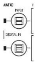
Signal from the two Inputs A and B will be passed to the Routing section if the LEDs in the two INPUT keys are lit.
- Press to activate/deactivate.
Input Trim
In Edit mode you have access to individual Input trim parameters on channels A and B.
Parametric EQ (Input EQ)
The Controller holds two parametric EQ sections. The first is located on the Input side of the Routing matrix. One for channel A and one for channel B.
| Par EQ A, B Type: Gain Freq: Width/Slope: | |
| Band 1 Lo Shelve 20 Hz – 20 kHz 6dB/OctHi Pass 20 Hz – 20 kHz 12dB/OctPar EQ ±18 dB 20 Hz – 20 kHz 0,03 – 4 Oct | |
| Band 2 Par EQ ±18 dB 20 Hz – 20 kHz 0,03 – 4 Oct | |
| Band 3 Par EQ ±18 dB 20 Hz – 20 kHz 0,03 – 4 Oct | |
| Band 4 Par EQ ±18 dB 20 Hz – 20 kHz 0,03 – 4 Oct | |
| Lo Pass 20 Hz – 20 kHz 12dB/OctHi Shelve 20 Hz – 20 kHz 6dB/Oct |
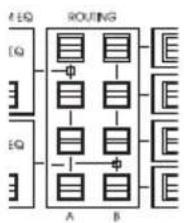
Routing section -as illustrated on the Front panel
flowchart
graph TD
    EQ1["EQ"] --> A["A"]
    EQ2["EQ"] --> A["A"]
    EQ3["EQ"] --> A["A"]
    EQ4["EQ"] --> A["A"]
    EQ5["EQ"] --> A["A"]
    EQ6["EQ"] --> A["A"]
    EQ7["EQ"] --> A["A"]
    EQ8["EQ"] --> A["A"]
    EQ9["EQ"] --> A["A"]
    EQ10["EQ"] --> B["B"]
    EQ11["EQ"] --> B["B"]
    EQ12["EQ"] --> B["B"]
    EQ13["EQ"] --> B["B"]
    EQ14["EQ"] --> B["B"]
    EQ15["EQ"] --> B["B"]
    EQ16["EQ"] --> B["B"]
    EQ17["EQ"] --> B["B"]
    EQ18["EQ"] --> B["B"]
    EQ19["EQ"] --> B["B"]
- alternative illustration of the Routing section

flowchart
graph TD
    subgraph In_A
        A1["In A"] --> B1["Processing"]
        A2["In A"] --> B2["Processing"]
        A3["In A"] --> B3["Processing"]
        A4["In A"] --> B4["Processing"]
    end
    subgraph In_B
        B1 --> C1["In B"]
        B2 --> C2["In B"]
        B3 --> C3["In B"]
        B4 --> C4["In B"]
    end
    D1["Outputs 1-4"] --> B1
    D2["Outputs 1-4"] --> B2
    D3["Outputs 1-4"] --> B3
    D4["Outputs 1-4"] --> B4
    style In_A fill:#f9f,stroke:#333
    style In_B fill:#ccf,stroke:#333
The Routing section is the "railway-station" in the signal chain. The signal present on Inputs A/B can via the 2x4 select switches be routed to none, any or all of the four Output channels.
From the Routing section out the four channels are individually processed with separate X-Over, EQ, Delay, Limiter and Output blocks.
Notice that the front panel layout is identical to the actual signal flow through the unit.
Example:
Input A distributed to Output 1 and 2 Input B distributed to Output 3 and 4

A typical example of a stereo setup with split in both sides.
More examples on pages 10 to 13.
X-Over

For optimal settings please refer to your speaker specifications.
The MACH M20.04 may hold presets that perfectly match your speaker configuration.
| X-Over A,B: Type: Gain Freq: Width/Slope: | |
| X-Over Hi Pass N/A 20 Hz – 20 kHz 1st orderLo Pass Butterworth 2. | Butterworth 3.Butterworth 4.Bessel 2.Bessel 3.Bessel 4.Linkw.Riley 2.Linkw.Riley 4. |
Delay for each speaker Line. Especially for compensating for speaker placement.
Range: 0 to 200ms

Limiter
A Limiter for each speaker line is available.
Correctly set the Limiter will prevent peaks from damaging your speakers.
Threshold
Range: -40 to 0 dB
Sets the Threshold/activation point for the Limiter.
Ratio
Range: Off to Infinity
Sets the amount of attenuation.
Attack
Range: 1 to 100ms
The Attack time is the time it takes for the Limiter to reach the gain-reduction specified by the Ratio parameter.
Release
Range: 100ms to 7 sec.
Sets the time it will take for the Limiter to release the attenuation of the signal.
Output
Range: 6; 12; 18; 22dBu
It is important that the Controller Outputs are correctly matched to the Input range of your amplifier. Please refer to your amplifiers manual for correct settings.
Analog Inputs
Connectors:
XLR
Impedance, Bal / Unbal:
21 kOhm / 13 kOhm
Max. / Min. Input Level @ 0 dBFS:
+24 dBu / 0 dBu
Sensitivity Range @ 12 dB headroom:
-12 dBu to +12 dBu
A to D Conversion:
24 bit, 128 x oversampling bitstream
A to D Delay:
0.70 ms / 0.65 ms @ 44.1 kHz / 48 kHz
Dynamic Range:
typ < -110 dB, 22 Hz to 22 kHz
THD:
typ < -110 dB @ 1 kHz, -1 dBFS
Frequency Response:
+0/-0.1 dB, 20 Hz to 20 kHz
Crosstalk:
typ < -100 dB, 20 Hz to 20 kHz
Analog Outputs
Connectors:
XLR
Impedance Bal / Unbal:
40 Ohm / 20 Ohm
Max. Output Level:
+14 dBu
D to A Conversion:
24 bit, 128 x oversampling bitstream
D to A Delay:
0.68 ms / 0.63 ms @ 44.1 kHz / 48 kHz
Dynamic Range:
typ < -110 dB typ, 22 Hz to 22 kHz
THD:
typ < -110 dB (0.0014 %) @ 1 kHz, +13 dBu
Frequency Response:
+0/-0.5 dB, 20 Hz to 20 kHz
Crosstalk:
typ < -100 dB, 20 Hz to 20 kHz
EMC Complies with:
EN 55103-1 and EN 55103-2
Safety Certified to:
FCC part 15, Class B, CISPR 22, Class B
IEC 65, EN 60065, UL6500 and CSA E60065
CSA FILE #LR108093
Environment Operating Temperature:
32^ F to 122^ F (0°C to 50°C)
Storage temperature:
-22°F to 167°F (-30°C to 70°C)
Humidity:
Max. 90 % non-condensing
General
Finish:
Anodized aluminum front, plated and painted steel chassis
Display:
2 x 16 character LCD
Dimensions:
19" x 1.75" x 8" (483 x 44 x 105.6 mm)
Weight:
3.3 lbs (1.5 kg)
Mains Voltage:
100 to 240 VAC, 50 to 60 Hz (auto-select)
Power Consumption:
<15 W
Warranty Parts and labor:
1 year
Due to continuous development these specifications are subject to change without notice.
Supplier
Mach Speakers A/S
www.mach.dk
Perspektivvej 2. DK-9900 Frederikshavn. Denmark. Tel : +45 7215 0852.
Fax :+45 9843 1415. E-Mail: mach-service@martin.dk.
- IMPORTANT SAFETY INSTRUCTIONS
- Warning!
- Caution:
- Service
- EMC / EMI.
- For the customers in Canada:
- Certificate Of Conformity
- Loudspeaker Management Controller
- TABLE OF CONTENTS
- INTRODUCTION
- OPERATION
- APPENDIX
- The MACH M20.04 incorporates the following fully configurable features:
- FRONT PANEL OVERVIEW
- POWER On/Off
- INPUT METERS
- DISPLAY
- DIGITAL IN select
- INPUT A/B
- PAR EQ A/B
- ROUTING matrix
- X-OVER keys
- EQ
- DELAY LINE
- LIMITER
- OUTPUT
- RECALL
- STORE
- ENTER
- LOCK
- ADJUST encoder
- EDIT
- SETUP
- CURSOR keys
- REAR PANEL
- TYPICAL SETUPS
- Stereo Setup - with subs
- Analog:
- Using the Digital Input
- Stereo Setup
- Analog
- Configuration overview
- 3/4 way setup - Bi-Amp Mid/High
- For each side:
- System Distribution - with delay
- Dual Source Mono - Dual Zone
- Editing Parameters
- Parameters in the Edit mode:
- Recall
- To recall a preset
- Store
- To store a preset
- The Setup menu
- Output Range
- Input Sensitivity
- Delay Unit
- Lock Function - introduction
- There are two basic Lock modes
- Timing function
- Lock Code
- Digital In
- Input Bypass A/B - Input Trim
- Input Trim
- Parametric EQ (Input EQ)
- Example:
- X-Over
- Limiter
- Threshold
- Ratio
- Attack
- Release
- Output
- Analog Inputs
- Analog Outputs
- General
- Mach Speakers A/S
Brand : MARTIN
Model : M20.04
Category : Loudspeaker