IES02-D12-OI04 - Security Camera Illustra - Free user manual and instructions
Find the device manual for free IES02-D12-OI04 Illustra in PDF.


| Product Type | Security Camera, 2MP Varifocal Dome |
| Model | Illustra Essentials Gen 4 IES02-D12-OI04 |
| Image Sensor | 2MP (1920x1080) |
| Lens | Varifocal 2.7-13.5mm, motorized zoom and focus |
| Day/Night | True Day/Night with IR cut filter, IR illuminator |
| Wide Dynamic Range | True WDR and Digital WDR |
| Video Compression | H.264, H.265, MJPEG |
| Max Resolution | 1920 x 1080 (1080p) at 30fps |
| Streaming | Dual stream, up to 3 concurrent streams |
| Power | 12V DC or PoE (IEEE 802.3af Class 3) |
| Network Interface | RJ-45 10/100 Ethernet, PoE |
| Edge Storage | Micro SD card slot for local recording |
| Housing | Outdoor, vandal-resistant, clear dome, white |
| Mounting | Wall/ceiling mount with 3-axis adjustment |
| Security | Password protection, HTTPS, IEEE 802.1x, IP filtering |
| Analytics | Motion detection, face detection, and other events |
| Operating Temperature | Outdoor rated, typical -20°C to 50°C |
| Included Accessories | Quick guide, desiccant, Torx wrench, anchors, screws, mounting template |
Frequently Asked Questions - IES02-D12-OI04 Illustra
User questions about IES02-D12-OI04 Illustra
0 question about this device. Answer the ones you know or ask your own.
Ask a new question about this device
Download the instructions for your Security Camera in PDF format for free! Find your manual IES02-D12-OI04 - Illustra and take your electronic device back in hand. On this page are published all the documents necessary for the use of your device. IES02-D12-OI04 by Illustra.
USER MANUAL IES02-D12-OI04 Illustra
Illustra Essentials Gen 4 Series
Installation and Configuration Guide

natural_image
Technical line drawing of a ceiling-mounted security guard (no text or symbols)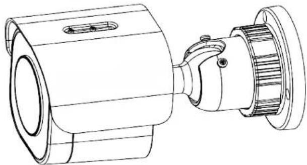
natural_image
Technical line drawing of a mechanical device with cylindrical and flanged components (no text or symbols)Notice
Please read this manual thoroughly and save it for future use before attempting to connect or operate this unit.
The information in this manual was current when published. The manufacturer reserves the right to revise and improve its products. All specifications are therefore subject to change without notice.
Copyright
This product includes advanced facial detection technology developed by INTELLIVISION.
Under copyright laws, the contents of this manual may not be copied, photocopied, reproduced, translated or reduced to any electronic medium or machine-readable form, in whole or in part, without prior written consent of Tyco Security Products.
© 2020 Tyco Security Products. All rights reserved.
Tyco Security Products
6600 Congress Avenue
Boca Raton, FL 33487 U.S.A.
Customer Service
Thank you for using American Dynamics products. We support our products through an extensive worldwide network of dealers. The dealer through whom you originally purchased this product is your point of contact if you need service or support. Our dealers are empowered to provide the very best in customer service and support. Dealers should contact American Dynamics at (800) 507-6268 or (561) 912-6259 or on the web at www.americandynamics.net.
Trademarks
The trademarks, logos, and service marks displayed on this document are registered in the United States [or other countries]. Any misuse of the trademarks is strictly prohibited and Tyco Security Products will aggressively enforce its intellectual property rights to the fullest extent of the law, including pursuit of criminal prosecution wherever necessary. All trademarks not owned by Tyco Security Products are the property of their respective owners, and are used with permission or allowed under applicable laws.
Product offerings and specifications are subject to change without notice. Actual products may vary from photos. Not all products include all features. Availability varies by region; contact your sales representative.
Table of Contents
Overview . 5
Illustra Essentials Gen 4 Dome cameras 6
Product overview 6
Installation 6.
Illustra Essentials Gen 4 Bullet cameras 13
Product overview .13....
Installation 13
Network Topology 20
Network Connection 22
Default IP Address 22
DHCP 23
Managing cameras with the Illustra Connect tool.... 24
Configuration 27
Live menu 30
Quick Start Menu 32
Basic Configuration 32
Video Menu 47
Streams 47
Picture Settings.... 50
Privacy Zones 59
Events and Actions Menu.... 62
Event Settings 62
Event Actions 65
Analytics 66
Event Logs 69
Security 71
Security Status 71
Security Status 73
Users 73
HTTP / HTTPS_75
IEEE 802.1x.77....
Firewall 77....
Remote Access.79....
Session Timeout 81
Network Menu .82....
TCP/IP 82
FTP 83
SMTP 85
SNMP 86
Heartbeat 87
Dynamic DNS 87
System 89
Maintenance 89
Date / Time....92
Health Monitor 93
Logs 93
About 94
Edge Recording 96
Micro SD Card Management 96
Record Settings 98
Event Download 99
Appendix A: User Account Access 100
Appendix B: Using Media Player to View RTSP Streaming 102
Appendix C: Stream Tables.... 103
Appendix D: Camera Defaults 104
Appendix E: Technical Specifications 112
End User License Agreement (EULA) 120
This Illustra Essentials Gen 4 Installation and Configuration Guide is a user manual which provides physical properties, installation, and configuration information of the cameras in Table 1 on Page 5.
Table 1 Product codes
| Product Code | Model Name Description | |
| IES02-D10-OI04 | Illustra Essentials Gen 4, 2MP Fixed Dome camera | Illustra Essentials Gen 4, 2MP Dome, 2.8mm, Outdoor, vandal, clear, white, TDN w/IR |
| IES02-D12-OI04 | Illustra Essentials Gen 4, 2MP Varifocal Dome camera | Illustra Essentials Gen 4, 2MP Dome, 2.7-13.5mm, Outdoor, vandal, clear, white, TDN w/IR |
| IES02-B10-BI04 | Illustra Essentials Gen 4, 2MP Fixed Bullet camera | Illustra Essentials Gen 4, 2MP Bullet, 2.8mm, Outdoor, vandal, white, TDN w/IR |
| IES02-B12-BI04 | Illustra Essentials Gen 4, 2MP Varifocal Bullet camera | Illustra Essentials Gen 4, 2MP Bullet, 2.7-13.5mm, Outdoor, vandal, white, TDN w/IR |
The first portion of this guide contains information pertaining specifically to the aforementioned cameras.
- For the Illustra Essentials Gen 4 Dome cameras, refer to Illustra Essentials Gen 4 Dome cameras on page 6.
- For the Illustra Essentials Gen 4 Bullet cameras, refer to Illustra Essentials Gen 4 Bullet cameras on page 13.
The second portion of this guide contains information regarding the Illustra User Web Interface and the web configuration of the aforementioned cameras. Refer to Configuration on page 27 for procedural information pertaining to camera configuration.
Illustra Essentials Gen 4 Dome cameras
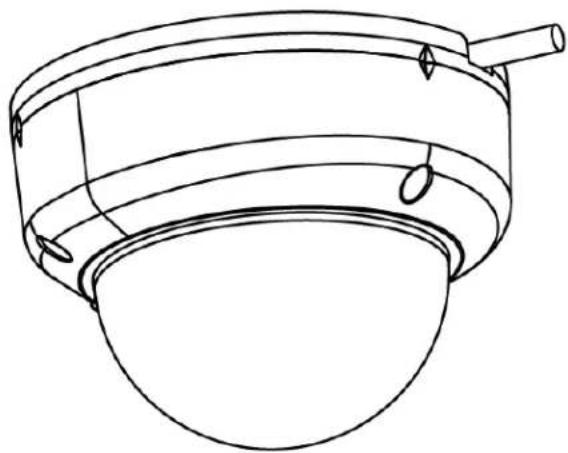
This chapter provides product features, installation procedures, and connection information regarding the Illustra Essentials Gen 4 Dome cameras.
Product overview
This chapter explains the installation of the Illustra Essentials Gen 4 2MP Dome cameras. Product codes and description of the cameras are provided in Table 2 on page 6.
Table 2 Product code and description of the Essential Gen 4 2MP Dome cameras
| Product Code | Model Name | Description |
| IES02-D10-OI04 | Illustra Essentials Gen 4, 2MP Fixed Dome camera | Illustra Essentials Gen 4, 2MP Dome, 2.8mm, Outdoor, vandal, clear, white, TDN w/IR |
| IES02-D12-OI04 | Illustra Essentials Gen 4, 2MP Varifocal Dome camera | Illustra Essentials Gen 4, 2MP Dome, 2.7-13.5mm, Outdoor, vandal, clear, white, TDN w/IR |
Installation
In the box
Check everything in the packing box matches to the order form and the packing slip. In addition to this guide, items below are included in the packing box.
• 1 x Essentials Indoor / Outdoor Dome camera
• 1 x Printed Quick Guide
- 1 x Desiccant
- 1 x Torx Wrench
- 3 x Plastic Anchors
- 3 x Tapping Screws
• 1 x Mounting Guide Pattern
Contact your dealer if any item is missing.
Installation tools
The following tools assist with installation:
- Drill
- Screw Drivers
- Wire cutters
Quick reference
- Default IP: 192.168.1.168 (DHCP enabled)
- Default Username: admin
- Default Password: admin
• Power: 12Vdc / PoE (IEEE 802.3af Class 3)
Checking appearance
When first unboxing, check whether if there is any visible damage to the appearance of the unit and its accessories. The protective materials used for the packaging should be able to protect the unit from most types of accidents during transportation. Remove the protective part of the unit when every item is checked in accordance with the list in Installation tools on page 7.
Procedure 1 Disassembling the camera.
Step Action
1 Use the Torx wrench to loosen the three screws on the camera top cover (1) (Figure 3) and gently remove the cover (2) (Figure 3).
Figure 3 Removing the camera top cover

- End -
Internal Interface pictorial index
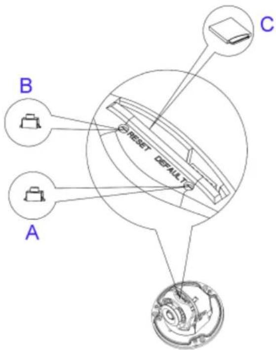
Figure 4 Internal interface pictorial index
Table 5 Internal interface pictorial index descriptions
| Name Description | ||
| A | Reboot Button | Press and release the button to reboot the camera. |
| B | Reset Button Press | the button for 1 second to reboot the camera. |
| C | Micro SD card slot | Insert a micro SD card into the slot for video recording and file storage. |
Procedure 2 Mounting the camera
Step Action
1 Place the mounting template on the wall / ceiling and drill three ∅4.5mm holes.
2 Insert the three plastic anchors into the three holes.
3 Determine how the camera pigtail cable should be routed:
• Through the cable entry on top of the camera (Figure 6)
Note: If required then drill a cable hole on the wall as identified on the mounting template.
OR
• Through the cable side entry slot (Figure 7)
Note: You do not need to drill a cable hole on the wall as identified on the mounting template when using the cable side entry slot.
4 Route the camera pigtail cable as per one of the options in step 3 and place the camera onto the wall / ceiling and align the holes on the camera with the three holes on the wall / ceiling.
Figure 6 Cable hole on top of the camera body

natural_image
Technical line drawing of a mechanical component with mounting holes and central shaft (no text or symbols)Figure 7 Cable side entry slot
natural_image
Line drawing of a cylindrical object with a handle and circular opening, resembling a lamp or container (no text or symbols)5 Insert the three tapping screws (1) (Figure 8) into the three holes on the camera body and using the screw driver securely attach the camera to the wall / ceiling.
Figure 8 Inserting the three tapping screws into the camera body

natural_image
Technical line drawing of a mechanical assembly with labeled components (no text or symbols)- End -
Procedure 3 Adjusting the camera position
The camera has three axes to adjust the field of view for different Applications (Figure 9). While screening live view on your monitor, adjust the axes as per the information below.
Figure 9 Adjusting the camera position

- Pan Adjustment (A – Figure 9) Rotate the lens base until satisfied with the field of view. Please DO NOT rotate over the default limit of >355°.
- Tilt Adjustment (B – Figure 9) Tilt the camera lens within the certain range (70°) to your desired field of view.
- Horizontal Rotation (C – Figure 9) Rotate the 3D assembly in the lens, DO NOT turn the assembly more than the limit (± 355°) as this may result in the internal cables becoming twisted, disconnected, or broken.
- End -
Procedure 4 Assembling the camera
Step Action
1 Place the camera top cover (2) (Figure 10) onto the camera body (1) (Figure 10).
2 Use the Torx wrench to securely attach the three Torx screws located on the camera top cover (2) (Figure 10).
Figure 10 Attaching the camera top cover

- End -
Procedure 5 Powering up the camera
- 12Vdc: Connect the 12Vdc cable to the DC 12V terminal. OR
- PoE: Connect the RJ-45 jack to a PoE compatible network device that supplies power through the Ethernet cable.
- End -
Warnings
- This product is intended for professional installation, please follow local wiring regulations.
- To meet EU security immunity requirements this product should be used with an Uninterruptable Power Supply to feed the mains input of any power adaptor.
- The product should be powered by a limited power supply (LPS) sized according to the product rating label.
- The LAN symbol on the unit means this is not intended for connection to a public network or a LAN from a different building.
- Do not install where children are likely to have access.
Illustra Essentials Gen 4 Bullet cameras
This chapter provides product features, installation procedures, and connection information regarding the Illustra Essentials Gen 4 Bullet cameras.
Product overview
This chapter explains the installation of the Ilustra Essentials Gen 4 2MP Bullet cameras. Product codes and description of the cameras are provided in Table 11 on page 13.
Table 11 Product code and description of the Essentials Gen 4 Bullet cameras
| Product Code | Model Name | Description |
| IES02-B10-BI04 | Illustra Essentials Gen 4, 2MP Fixed Bullet camera | Illustra Essentials Gen 4, 2MP Bullet, 2.8mm, Outdoor, vandal, white, TDN w/IR |
| IES02-B12-BI04 | Illustra Essentials Gen 4, 2MP Varifocal Bullet camera | Illustra Essentials Gen 4, 2MP Bullet, 2.7-13.5mm, Outdoor, vandal, white, TDN w/IR |
Installation
In the box
Check everything in the packing box matches to the order form and the packing slip. In addition to this guide, items below are included in the packing box.
• 1 x Essentials Outdoor IR Bullet camera
• 1 x Printed Quick Start Guide
- 1 x Torx wrench
- 3 x Plastic anchors
- 3 x Tapping screws
- 1 x Mounting template
• 1 x T6 Wrench 130mm X 30mm (Varifocal Camera)
Contact your dealer if any item is missing.
Installation tools
The following tools assist with installation:
- 1 x Drill
- 1 x Screwdrivers
- 1 x Wire cutters
Quick reference
- Default IP: 192.168.1.168 (DHCP enabled)
- Default Username: admin
- Default Password: admin
• Power: PoE (IEEE 802.3af Class 3)
Figure 12 Camera parts and connections
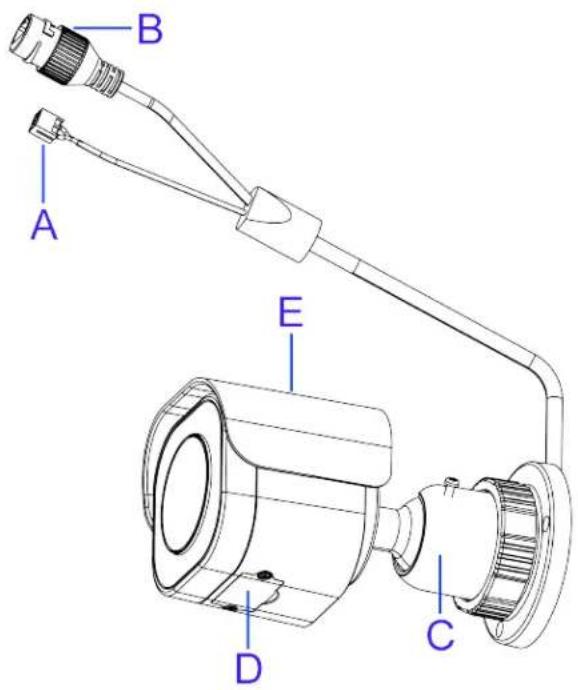
Table 13 Camera parts and connections descriptions
| Name Description | ||
| A | DC 12V Port | For powering on the camera through the DC12V power source. |
| B | RJ-45 Ethernet / PoE Port | Connect an Ethernet cable terminated with RJ-45 connector to the PoE RJ-45 port for both power supply and network connectivity purposes simultaneously. |
| C | Mounting Bracket | To mount the camera onto different environments, the mounting bracket is designed with three axes for flexible adjustment. |
| D | Internal Interface Cover | Use a screwdriver to loosen the 2 screws and open the cover to access the internal interfaces including the “RESET” and “DEFAULT” button, “Micro SD Card Slot”, and LED’s. |
| E | Protection Shield Hood | For minimizing the effects of rain and sunlight on image quality. |
Figure 14 Camera internal interface and descriptions

Table 15 Camera internal interface descriptions
| Name Description | |
| Reset Button | Press and release to reboot the camera. |
| Signal LED (RED) Indicates network data is being transmitted. | |
| Micro SD card slot Insert a micro SD card into the slot for recording and file storage | |
| Power LED (GREEN) | Indicates camera is powered on. |
| Default Button | Press the button for 6 seconds to restore to the factory default tings. |
Procedure 6 Mounting the camera
Step Action
1 Place the mounting template on the mounting surface and drill three 6mm (0.25") holes.
2 Insert the three plastic anchors (1) (Figure 16) into the three holes.
3 Place the camera on the mounting surface and align the three holes on the camera with the three holes on the mounting surface.
4 Insert the three tapping screws (2) (Figure 16) into the three holes on the camera body and using the screw driver securely attach the camera to the wall / ceiling.
Figure 16 Plastic achors and camera screws

- End -
Wiring the camera
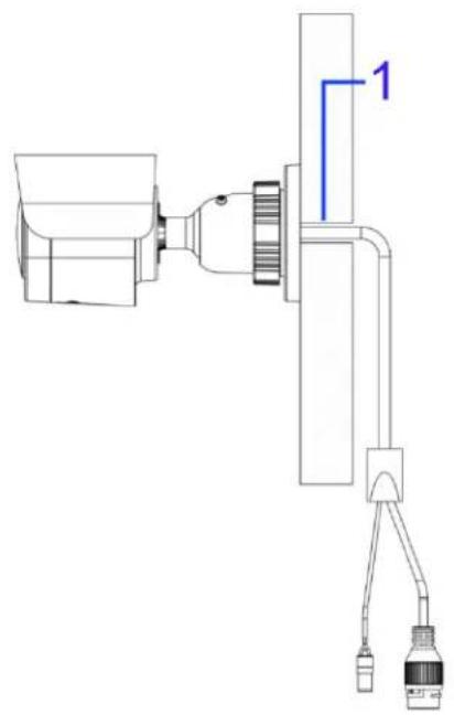
You can run the cable through the mounting bracket or you can run the cable through the cable side entry on the mounting bracket.
Step Action
1 When mounting the camera, pass the cable through the mounting bracket and then through the:
• hole on the mounting surface (1) (Figure 17).
OR
- the cable side entry on the mounting bracket (1) (Figure 18).
Figure 17 Mounting surface cable hole
natural_image
Technical line drawing of a mechanical assembly with labeled component 1 (no text or symbols beyond label)Figure 18 Camera cable side entry slot

natural_image
Technical line drawing of a mechanical assembly with labeled component 1 (no text or symbols beyond label)2 Connect an Ethernet cable terminated with the RJ-45 connector to the PoE port and ensure that the other end of the Ethernet cable is connected with a PoE compatible network device.
3 If necessary, connect the DC 12V power source to the DC 12V port.
- End -
Adjusting the camera position
The camera has three axes to adjust the field of view for different Applications (Figure 19). While screening live view on your monitor, adjust the axes as per the information below.
Figure 19 Adjusting the camera position

- Tilt Adjustment (A - Figure 19) Tilt this joint to adjust the camera vertically. The Tilt range is 0^ - 90^ .
- Pan Adjustment (B - Figure 19) Rotate this joint to adjust the camera horizontally. DO NOT rotate over the default limit of ± 360^ .
- Locking Ring (C - Figure 19) Rotating the C ring counter-clockwise, the Pan & Tilt joints loosen and you can adjust for different angles. Rotating the C ring clockwise fastens the pan & tilt joints altogether.
- End -
Adjusting the protection shield hood
The protection shield hood protects the camera from both sunlight and rain.
Step Action
1 Use the L-Key (1) (Figure 20) to loosen the two screws located on the protection shield hood.
2 Slide the protection shield (2) (Figure 20) forward or backward until the correct position is found.
Figure 20 Adjusting the protection shield hood
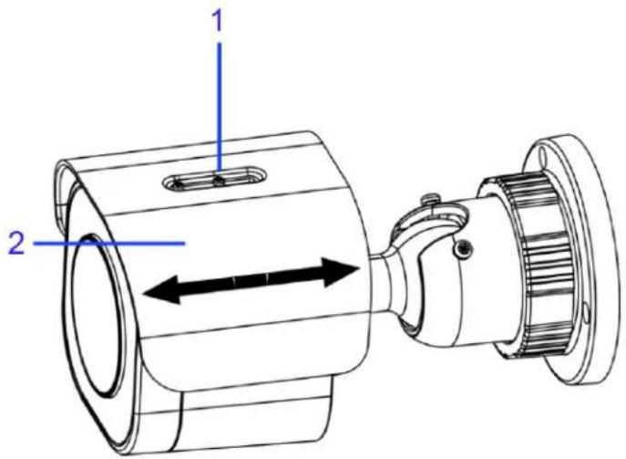
3 Use the L -Key and secure the two screws located on the protection shield hood.
Note: Be careful not to excessively adjust the hood or you may damage the camera housing.
- End -
Network Topology
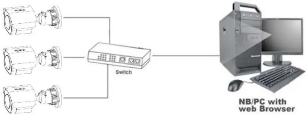
The Illustra Essentials Gen 4 cameras deliver video images in real-time using the internet and intranet. It is equipped with an Ethernet RJ-45 network interface.
The following images illustrate the network topologies of the Dome and Bullet cameras.
Essentials Gen 4 Dome Camera Topology
Figure 21 Dome Cameras Network Topology Type I.

Figure 22 Dome Cameras Network Topology Type II

flowchart
graph LR
    A["Security Camera"] --> C["Switch"]
    B["Security Camera"] --> C["Switch"]
    D["Security Camera"] --> C["Switch"]
    C --> E["Computer with Web Browser"]
Essentials Gen 4 Bullet Camera Topology
Figure 23 Bullet Cameras Network Topology Type I.

Figure 24 Bullet Cameras Network Topology Type II
flowchart
graph TD
    A["Camera 1"] --> C["Switch"]
    B["Camera 2"] --> C["Switch"]
    D["Camera 3"] --> C["Switch"]
    C --> E["Computer"]
    style A fill:#f9f,stroke:#333
    style B fill:#f9f,stroke:#333
    style D fill:#f9f,stroke:#333
    style E fill:#ccf,stroke:#333
Network Connection
Default IP Address
Since this is a network-based unit, an IP address must be assigned at the very first bootup. The default IP address of the unit is 192.168.1.168 and sub mask is 255.255.255.0.
However, if you have a DHCP server in your network, the unit obtains an IP address automatically from the DHCP server so that you do not need to change the IP address of the camera.
Note: If you assign the camera a Static IP address prior to DHCP being enabled, the camera first reboots for approximately 30 seconds and then remains accessible at its Static IP until it connects to a DHCP server.
- Connect to a PC directly: Directly connect the camera to a PC using a standard Ethernet cable. This requires POE switch or injector.
- Connecting a camera to a Local Area Network (LAN): To add the camera to an existing LAN, connect the camera to the POE hub or switch on your network.
Figure 25 Network connection diagram

flowchart
graph TD
    A["Client"] --> B["Network"]
    C["Client"] --> B
    D["Client"] --> B
    B --> E["PoE"]
    E --> F["Terminal Device"]
Default camera settings
The following table describes the default camera settings.
| Network Settings | Defaults |
| DHCP Enabled | |
| Static IP Address 192.168.1.168 | |
| Default Username admin | |
| Default Password | admin |
Note: At first login the user is prompted to change the default username and password.
Procedure 7 Connecting from a computer
Step Action
1 Ensure the camera and your computer are in the same subnet. 2 Check whether if the network is available between the unit and the computer by pinging the default IP address.
a Start a command prompt.
b Type "Ping 192.168.1.168". If the message "Reply from..." appears, it means the connection is available.
3 Start Internet Explorer and enter IP address: 192.168.1.168. A login window appears. In the window, enter the default user name: admin and password: admin to log in.
- End -
DHCP
On initial camera startup, and after a hardware factory reset, Dynamic Host Configuration Protocol (DHCP) is enabled by default and remains enabled until the camera receives either a DHCP address or is assigned a Static IP address.
Procedure 8 Enable DHCP
Step Action
1 Select Setup on the Web User Interface banner to display the setup menus.
2 Select the TCP/IP tab in the Basic Configuration menu.
3 Select the Enable DHCP check box to enable DHCP and disable manual settings.
4 Select Apply to save the settings.
The camera searches for a DHCP server. If one is found it connects to that server. If no connection is made to a DHCP server within two minutes, the camera goes to the default IP address 192.168.1.168, but continues to search for a DHCP address.
Note: If you assign the camera a Static IP address prior to DHCP being enabled, the camera first reboots for approximately 30 seconds and then remains accessible at its Static IP until it connects to a DHCP server.
- End -
Procedure 9 Disable DHCP
Step Action
1 Select Setup on the Web User Interface banner to display the setup menus.
2 Select the TCP/IP tab in the Basic Configuration menu.
3 Clear the Enable DHCP check box to disable DHCP and allow manual settings to be entered.
The default setting is 'Enabled'.
4 If Enable DHCP has been disabled:
a Enter the IPv4 Address in the IPv4 Address text box in the form xxx.xxx.xxx.xxx.The default setting is '192.168.1.168'
b Enter the Network Mask in the Network Mask text box xxx.xxx.xxx.xxx. The default setting is '255.255.255.0'
c Enter the Gateway IP address in Gateway text box xxx.xxx.xxx.xxx.
d Enter the Primary DNS Server in the Primary DNS Server text box xxx.xxx.xxx.xxx.
5 Select Apply to save the settings.
- End -
Managing cameras with the Illustra Connect tool
In addition to using the IE browser to access your camera, you can alternatively use the provided tool, Illustra Connect.
Illustra Connect is a management tool designed to manage your network cameras on the LAN. It can:
- set the IP addresses
• show connection status - manage firmware upgrades
- bulk configuration
• help you find multiple network cameras
Refer to Configuration on page 27 for further information regarding using the Illustra Connect tool for configuring the cameras.
Procedure 10 Connecting to the camera using Illustra Connect
Note:
Illustra Connect can only discover devices on the same subnet as its host computer. Therefore, the camera and the computer being used to configure it must be on the same subnet.
Step Action
1 Using a computer which is connected to the same network and subnet, install the Illustra Connect software.
The Illustra Connect software and the Illustra Connect manual are available to download on www.illustracameras.com
2 When the installation is complete, run Illustra Connect.
It searches the network and displays all compliant devices.
3 Select the camera you want to configure, locating it by its unique MAC address.
4 Right-click the camera and select Launch Web GUI Configuration. The camera Web User Interface displays.
- End -
Procedure 11 Connecting to the camera using the static IP address
Step Action
1 The camera attempts to obtain an IP Address from the DHCP Server. When no DHCP Server is available the camera is assigned a Static IP address of 192.168.1.168.
2 Open Microsoft Internet Explorer and enter the URL of the camera as 192.168.1.168. The camera sign in page displays.
Note:
The computer you use to configure the camera must have an IP address on the same subnet.
- End -
Procedure 12 Logging on to the camera web user interface
Step Action
1 When you select the camera, the sign in page displays. Select your preferred language from the drop-down menu.
2 Enter the username in the Username text box. The default username is admin.
3 Enter the password in the Password text box. The default password is admin.
4 Select Log in.
Note: The first time that you access the camera or after a factory reset the following two pop up windows are visible: A pop up window that requests the user to Define a Host ID and a pop up window that requests the user to select a Security Type. Please refer to the Define a Host ID section in Procedure 14 for further information on this.
5 The Live view page is visible. This displays the current view of the camera.
Note: When Standard security is selected and at first login the user is prompted to change the default password.
Note: When Enhanced security is selected and at first login the user is prompted to change the default username and password.
- End -
Procedure 13 Enabling the correct video orientation for a wall mounted camera
Step Action
1 Log on to the camera web user interface.
2 Select Setup on the camera web user interface banner to display the setup menus.
3 Select the Picture Basic tab from the Basic Configuration menu.
4 Select the required Orientation setting:
- Mirror
- Flip
5 The video pane updates to display the new settings.
Configuration
The following sections explain the how you can configure Illustra Essentials Gen 4 cameras using the Web User Interface.
Security Mode Profiles for First Time Connection
The Illustra Essentials Gen 4 cameras have features that allow for operation in a Standard Security mode or in an Enhanced Security mode.
When the camera is in Enhanced Security mode, you require a complex eight character Administrator password to make changes to these protocols.
Refer to Summary of Security Modes on page 28 for further information regarding the differences between Standard and Enhanced Security modes.
Accessing the Illustra Essentials Gen 4 Series Camera Web User Interface
Use the following procedure to access the camera Web User Interface.
Procedure 14 Logging in to the Camera
Step Action
1 Refer to Network Connection on page 22 for details on how to connect the camera to your network or computer.
2 When you select the camera, the sign in page displays.
3 Select your preferred language from the drop-down menu. The default language is English.
4 Enter the default username and password when prompted - Username: admin, Password: admin.
5 Click Log in. The camera Web User Interface displays. The first time that you access the camera, or after a factory reset, you are prompted to Define a Host ID and Select a Security Type.
- Define a Host ID: The admin user must enter a 6 character code for the Host ID that includes both letters and/or numbers. This unique password can be used to access the operating system files. The HostID is not stored on the camera for security reasons and must be presented to Illustra Technical Support when remote access to the operating system is required.
- Select a Security Type: Standard Security or Enhanced Security.
6 If you select the Standard Security option, password change is mandatory.
Note: Password complexity is set to require a minimum of 5 characters, 'admin' cant be used.
7 If you select the Enhanced Security option, a default admin username and password change is mandatory.
Note: The password must meet the following requirements:
Be a minimum of eight characters long.
Have at least one character from each of the following character groups:
• Upper-case letters - ABCDEFGHIJKLMNOPQRSTUVWXYZ
- Lower-case letters - abcdefghijklmnopqrstuvwxyz
• Numeric characters - 0123456789
- Special characters - @ % + \ / '! # \$^ ? : , () {} [] \~ - _
Note: Once the above steps are complete, the Live view page is visible. This displays the current view of the camera.
- End -
Summary of Security Modes
Standard Security:
- A default admin password change is mandatory.
- Changes to communication protocols are available to all users with appropriate privileges.
- Passwords complexity is set to require minimum of any 5 characters, 'admin' cant be used.
- Authentication method is set to basic by default.
Enhanced Security:
- Unsecure Protocols are disabled by default until enabled by a user.
- When you select enhanced security you must change the default 'admin' username and password.
- Discovery protocols are disabled by default until enabled by a user.
- Changes in the protocols are only be available to a user with administrative privileges and require that user to reenter their password.
- Authentication method is set to Digest by default.
- HTTPS protocol is enabled by default.
- Passwords for all accounts will meet the following password complexity requirements:
• Minimum characters: 8
- The password cannot contain the username
- Have at least one character from each of the following character groups:
• Upper-case letters - ABCDEFGHIJKLMNOPQRSTUVWXYZ
- Lower-case letters - abcdefghijklmnopqrstuvwxyz
• Numeric characters - 0123456789
- Special characters - @ % + \ / '! # \$^ ? : , () {} [] \~ - _
- Changing protocols require an administrator to re-enter their password
Changing the Camera Web User Interface Language
Use the following procedure to change the language used in the camera Web User Interface.
Procedure 15 Change the Camera Web User Interface Language
Step Action
1 Open the camera sign in page. If you are already logged in to the Web User Interface, select Log Off to display the sign in page.
2 Select your preferred language from the drop-down menu:
- English
- Arabic
- Czech
- Danish
- German
- Spanish
- French
- Hungarian
- Italian
- Japanese
- Korean
- Dutch
- Polish
- Portuguese
- Swedish
- Turkish
- Chinese Simplified
- Chinese Traditional
- Russian
- Hindi
The default language is English.
3 Enter the Username.
4 Enter the Password.
5 Select Log in.
The camera web User Interface displays in the selected language.
- End -
Live menu
When you log in to the Illustra Web User Interface, the Live menu appears, as seen in Figure 26 on page 30.
Figure 26 Live menu page

Displaying the Live View Page
Display the live camera view page.
Procedure 16 Display Live View Page
Step Action
1 Select Live in the Web User Interface banner. The Live view page displays.
2 Select a video stream from Stream to view.
3 Select a percentage from Scale to change the display size of the video pane:
• 25%
- 50%
• 75%
• 100%
The default setting is 100%.
- End -
Accessing the Setup Menus from Live View
Setup menus within the Web User Interface are restricted by user account access levels. Refer to Appendix A: User Account Access on page 100 for details on the features which are available to each role.
Procedure 17 Access Setup Menus from Live View
| Step | Action |
| 1 | On theLivemenu, click theSetuptab. |
| Note:When an admin user logs in for the first time the Live menu displays. After this, on each login the Stream page on the Video menu displays. | |
| - End - | |
Quick Start Menu
When you select the Quick Start menu, the Basic Configuration Page displays, as shown in Figure 27 on page 32.
Note: When an admin user logs in for the first time the Basic Configuration page displays. After this, on each login the Video > Streams page displays.
Figure 27 Basic Configuration Menu

Basic Configuration
The Basic Configuration menu provides access to the most common features required when setting up a camera for the first time and is only available to an 'admin' user. The following tabs are displayed:
- TCP/IP
• Video Stream Settings - Picture Basic
• Picture Additional - Date Time
- OSD
TCP/IP
Configure the IPv4 and IPv6 network settings on the camera.
Note: When you perform a factory reset or reboot the unit searches for the last known IP address. If this is not available it reverts to the default IP address of 192.168.1.168. This could result in duplicate IP addresses. Refer to Quick Start Menu on page 32 for more information.
DHCP
On initial camera startup, and after a hardware factory reset, Dynamic Host Configuration Protocol (DHCP) is enabled by default and remains enabled until the camera receives either a DHCP address or is assigned a Static IP address.
Procedure 18 Enable DHCP
Step Action
1 Select Setup on the Web User Interface banner to display the setup menus.
2 Select the TCP/IP tab in the Basic Configuration menu.
3 Select the Enable DHCP check box to enable DHCP and disable manual settings.
4 Select Apply to save the settings.
The camera searches for a DHCP server. If one is found it connects to that server. If no connection is made to a DHCP server within two minutes, the camera goes to the default IP address 192.168.1.168, but continues to search for a DHCP address.
Note: If you assign the camera a Static IP address prior to DHCP being enabled, the camera first reboots for approximately 30 seconds and then remains accessible at its Static IP until it connects to a DHCP server.
- End -
Procedure 19 Disable DHCP
Step Action
1 Select Setup on the Web User Interface banner to display the setup menus.
2 Select the TCP/IP tab in the Basic Configuration menu.
3 Clear the Enable DHCP check box to disable DHCP and allow manual settings to be entered.
The default setting is 'Enabled'.
4 If Enable DHCP has been disabled:
a Enter the IPv4 Address in the IPv4 Address text box in the form xxx.xxx.xxx.xxx. The default setting is '192.168.1.168'
b Enter the Network Mask in the Network Mask text box xxx.xxx.xxx.xxx. The default setting is '255.255.255.0'
c Enter the Gateway IP address in Gateway text box xxx.xxx.xxx.xxx.
d Enter the Primary DNS Server in the Primary DNS Server text box xxx.xxx.xxx.xxx.
5 Select Apply to save the settings.
IPv4
Configure the IPv4 network settings for the camera.
Procedure 20 Configure the IPv4 Settings
Step Action
1 Select Setup on the Web User Interface banner to display the setup menus.
2 Select the TCP/IP tab in the Basic Configuration menu.
3 Select the Enable DHCP check box to enable DHCP and disable manual settings.
OR
Clear Enable DHCP to disable DHCP and allow manual settings to be entered.
The default setting is 'Enabled'.
4 If Enable DHCP has been disabled:
a Enter the IPv4 Address in the IPv4 Address text box in the form xxx.xxx.xxx.xxx. The default setting is '192.168.1.168'
b Enter the Network Mask in the Network Mask text box xxx.xxx.xxx.xxx.
The default setting is '255.255.255.0'
c Enter the Gateway IP address in Gateway text box xxx.xxx.xxx.xxx.
d Enter the Primary DNS Server in the Primary DNS Server text box xxx.xxx.xxx.xxx.
5 Select Apply to save the settings.
- End -
IPv6
Enable or disable IPv6 on the camera.
Procedure 21 Enable/Disable IPv6
Step Action
1 Select Setup on the Web User Interface banner to display the setup menus.
2 Select the TCP/IP tab in the Basic Configuration menu.
3 Select the IPv6 Enable check box to enable IPv6 on the camera.
OR
Clear the IPv6 Enable check box to disable IPv6 on the camera.
The default setting is 'Enabled'.
If IPv6 is enabled the Link Local and DHCP address display beside 'Current IPv6 Addresses' if available.
- End -
Video Stream Settings
You can configure two video streams on the camera: Stream 1 and Stream 2.
Configuring the Web Video Stream
Adjust the settings for each video stream.
Procedure 22 Configure the Video Stream settings
| Step | Action |
| 1 | Select Setup on the Web User Interface banner to display the setup menus. |
| 2 | Select the Video Streams Settings tab in the Basic Configuration menu. |
| 3 | Select either Stream 1 or 2 from the Stream Number drop-down menu. |
| 4 | Select the required Codec from the drop-down list:H264H265MJPEGThe default setting is ‘H264’. |
Note: When you select H264 you can set the Profile. If you do not select either of these options then continue at step 6 below.
5 Select the required Profile from the drop-down list:
- Main
- High
The default setting is 'Main'.
6 Select the required Resolution from the drop-down menu.
The resolutions available depend on the type of camera sensor (megapixel).
Table 28 2MP Camera Stream Set A (all resolution, codes and frame rate combinations of 1 and 2 are valid)
| Normal Mode | |||||
| Resolution | Description | Max FPS | |||
| TWDR Off | TWDR | ||||
| Stream 1 | h.264, h.265, MJPEG | 1920 x 1080 | (1080p) 16:9 | 30 | 30 |
| 1600 x 900 | (HD+) 16:9 | 30 | 30 | ||
| 1280 x 720 | (720p) 16:9 | 30 | 30 | ||
| 1024 x 576 | (PAL+) 16:9 | 30 | 30 | ||
| 960 x 540 | 16:9 | 30 | 30 | ||
| 800 x 480 | 16:9 | 30 | 30 | ||
| 640 x 360 | (mHD) 16:9 | 30 | 30 | ||
| 480 x 270 | 16:9 | 30 | 30 | ||
| 320 180 | 16:9 | 30 | 30 | ||
| Stream 2 | h.264, h.265, MJPEG | 1920 x 1080 | (1080p) 16:9 | 30 | 30 |
| 1600 x 900 | (HD+) 16:9 | 30 | 30 | ||
| 1280 x 720 | (720p) 16: 9 | 30 | 30 | ||
| 1024 x 576 | (PAL+) 16:9 | 30 | 30 | ||
| 960 x 540 | 16:9 | 30 | 30 | ||
| 800 x 480 | 16:9 | 30 | 30 | ||
| 640 x 360 | (m HD) 16:9 | 30 | 30 | ||
| 480 x 270 | 16:9 | 30 | 30 | ||
| 320 x 180 | 16:9 | 30 | 30 | ||
Note: A maximum of three concurrent streams are supported by the camera. This includes shared streams.
7 Use the slider bar to select the Frame Rate (fps).
The settings for the 2MP cameras are:
- Stream 1 - 1 - 30 fps, default 30 fps.
- Stream 2 - 1 - 30 fps, default is 30 fps.
Note:FPS varies depending on other features - refer to the Essentials Gen 4 Release Notes for further information.
8 If H264 or H265 has been selected in step 4 then you can adjust the GOP Length [1-60].
Use the slider bar to select the GOP Length [1-60].
The default setting is 30.
9 If MJPEG has been selected, MJPEG Quality is enabled. Use the slider bar to select the MJPEG Quality.
The default setting is 50.
OR
10 If H264 or H265 has been selected in step 4, Rate Control is enabled. Select the required Rate Control by selecting the radio buttons:
• VBR (Variable Bit Rate)
• CBR (Constant Bit Rate)
• CVBR (Constrained Variable Bit Rate)
The default setting is 'CVBR'.
a If you select VBR, VBR Quality is enabled. Select the required VBR Quality from the drop-down menu. The default setting is High.
- Highest
- High
- Medium
- Low
- Lowest
OR
b If you select CBR, CBR Bit Rate is enabled. Use the slider bar to select the CBR Bit Rate. The default setting is 4000.
OR
c If you select CVBR, Max Bit Rate is enabled. Use the slider bar to select the Max Bit Rate. The default setting is 8000.
- End -
Picture Basic
Adjust Picture Rotation, Focus / Zoom and Exposure displayed in the video pane.
Picture Rotation
Configure the orientation and corridor mode settings. Both settings are optional.
Procedure 23 Configure Orientation Settings
Step Action
1 Select Setup on the Web User Interface banner to display the setup menus.
2 Select the Picture Basic tab from the Basic Configuration menu.
3 Select the required Orientation setting:
- Mirror
- Flip
Mirror and Flip settings are selected by default. The video pane updates to display the new settings.
Note: When wall mounting the camera you should select Flip and Mirror to correct the lens orientation.
- End -
Focus / Zoom
You can configure the focus and zoom using the Web User Interface. You can use the plus and minus arrows to fine tune the image. The Zoom slider bar is used to manually zoom in and out to manually configure to picture. The table below describes the features supported by each camera.
Table 29 Lens features supported for the Outdoor Dome
| Varifocal Dome | Varifocal Bullet | |
| Motorized Focus | X X | |
| Motorized Zoom | X X | |
| Lens Calibration | X X | |
| Auto One Touch | X X |
Procedure 24 Adjust Camera Focus / Zoom
Step Action
1 Select Setup on the Web User Interface banner to display the setup menus.
2 Select the Picture Basic tab from the Basic Configuration menu.
3 Select to start the video stream if it is not already active.
4 Use the arrows to manually configure the focus and the slider bar to adjust zoom settings until the image is clear. The video pane updates to display the new settings.
- End -
Procedure 25 Adjust Camera Focus using OneTouch Autofocus
1 Select Setup on the Web User Interface banner to display the setup menus.
2 Select the Picture Basic tab from the Basic Configuration menu.
3 Select to start the video stream if it is not already active.
4 In the Focus/Zoom section, click the One Touch button. The camera refocuses to the zoom level selected for the image.
The video pane updates to display the new settings.
Note: The user can create a ROI focus point for the camera to use during the one touch procedure - use the pencil icon and highlight the desired ROI.
- End -
Exposure
Configure the exposure settings for the camera.
Procedure 26 Configure Exposure Settings
Step Action
1 Select Setup on the Web User Interface banner to display the setup menus.
2 Select the Picture Settings tab from the Basic Configuration menu.
3 Select to start the video stream if it is not already active.
4 Select the Exposure Mode from the drop-down menu:
- Auto
- Manual
- Shutter Priority
5 Select the Exposure Method from the drop-down menu:
• Full Picture Weighted
- Upper
- Lower
- Center Weighted
- Spot
- Left
- Right
The default setting is center weighted.
6 Select the Min Exposure (sec) from the drop-down menu. The default setting is 1/10000s.
7 Select the Max Exposure (sec) from the drop-down menu. The default setting is 1/7.5s.
8 Select the Exposure Offset (F-stops) from the drop-down menu. The default setting is 1/8s.
9 Select the Exposure Offset (F-Stops) from the drop-down menu. The default setting is 0.
10 Select the Max Gain (db) from the drop-down menu. The default setting is 45db.
11 Select Exposure (sec) from the drop down.
12 The Default is 1/30.
13 Select Manual Gain from the drop down.
14 The Default is 0db.
15 Select the Frequency radio button for either 50Hz or 60Hz. The default setting is 60Hz.
16 Select or clear the check box for Flickerless Mode. This feature is not selected by default.
- When you select Flickerless Mode, the minimum and maximum exposure times are locked to 1/100 and 1/50 respectively (PAL) or 1/120 and 1/60 respectively (NTSC). This applies to all cameras referenced in this guide.
Procedure 27 Restore Exposure Defaults
Step Action
1 Select Setup on the Web User Interface banner to display the setup menus.
2 Select the Picture Settings tab from the Basic Configuration menu.
3 Select to start the video stream if it is not already active.
4 Select Exposure Defaults to restore the default settings.
- End -
Picture Additional
Configure Wide Dynamic Range, Day Night Mode, and Picture Adjustments including Brightness, Contrast, White Balance, Saturation and Sharpness which displays in the video pane.
Wide Dynamic Range
Wide Dynamic Range (WDR) is a feature that supports the viewing of high contrast scenes that include both bright and low light areas in the same field of view (FOV).
WDR Level allows you to adjust the WDR level to favor a underexposed or overexposed image. By selecting the lower end of the control, the image is underexposed which provides more detail in areas of bright but less details in areas of darkness. Selecting the higher end of the control, the image is overexposed which provides more detail in the dark areas but less details in the bright areas.
A typical use for this feature would be viewing a scene with both indoor and outdoor lighting conditions simultaneously, for example, in a warehouse area with an open bay door.
Digital Wide Dynamic
Digital wide dynamic range, enhancing detail in darker areas.
Procedure 28 Disable/Enable Wide Dynamic Range (WDR)
Step Action
1 Select Setup on the Web User Interface banner to display the setup menus.
2 Select the Picture Additional tab from the Basic Configuration menu.
3 Select the required WDR from the drop-down list:
- True WDR: Two shutter wide dynamic range, to compensate for bright and dark areas in the scene.
- Digital WDR: Digital wide dynamic range, enhancing detail in darker areas.
The default setting is Off.
4 When you select DigitalWDR in step 3 then you can select the WDR level.
5 Select the WDR level from the drop-down menu.
- End -
Day Night Mode
IR/DayNight Mode utilizes a series of specific camera functions to dramatically enhance low light performance.
When needed, the True TDN mechanism removes an IR Cut Filter (IRCF) from in front of the images allowing the camera to see in black and white (BW) and utilize additional near-infrared energy found in many lighting sources like halogen, moonlight, etc.
This, along with slowing down another function, the shutter speed, significantly improves low light performance rendering clear images where none could be viewed previously.
IR Illuminator
When the camera is in B/W mode it can utilize or see near-IR illumination; something the human eye cannot do. This can be extremely powerful when the dome is paired with 850\~950nm IR illuminators. With this combination a scene can be well lit with IR light that the dome can see but people cannot. This is great for areas where externally lighting is not allowed or there is a need for covert security.
Procedure 29 Enable / Disable IR Illuminator
Step Action
1 Select Setup on the Web User Interface banner to display the setup menus.
2 Select the Picture Additional from the Basic Configuration menu.
3 Select the Enable IR Illuminator check box to enable IR Illuminator.
OR
Clear the Enable IR Illuminatorcheck box to disable IR Illuminator.
The default setting is 'Enabled'.
- End -
Day Night Mode
The dome provides a black-and-white (B/W) mode to improve camera performance when the light level falls below certain thresholds. This allows clear images to be obtained under low-light conditions.
Procedure 30 Configure Day Night Mode
Step Action
1 Select Setup on the Web User Interface banner to display the setup menus.
2 Select the Picture Additional from the Basic Configuration menu.
3 Select a Day Night Mode setting from the drop-down menu:
- Auto Low-camera will adjust between BW and Color depending on light levels.
- Auto Mid - camera give a good balance of Color and BW depending on the scene.
- Auto High - increases the chance of switching to BW mode as light levels drop.
- Manual - a slider bar will display, the user can adjust the setting to suit the environment.
- Forced Color - enable full-time color mode.
- Forced B&W - enable full-time black and white mode.
The default setting is 'Auto Mid'.
- End -
Picture Adjustment
Adjust brightness, contrast and saturation of the image displayed on the video pane.
Procedure 31 Adjust the Brightness, Contrast and Saturation
Step Action
1 Select Setup on the Web User Interface banner to display the setup menus.
2 Select the Picture Additional tab from the Basic Configuration menu.
3 Select to start the video stream if it is not already active.
The video pane will display the current camera view.
4 Use the slider bars to adjust:
- Brightness
- Contrast
- Saturation
- Hue
- Sharpness
The values range from 1% to 100%. The video pane updates to display the new settings.
- End -
Procedure 32 Restore Picture Balance Defaults
Step Action
1 Select Setup on the Web User Interface banner to display the setup menus.
2 Select the Picture Settings tab from the Basic Configuration menu.
3 Select Defaults to restore the default settings.
The default values are:
- Brightness: 50%
- Contrast: 50%
- Saturation: 50%
- Sharpness: 50%
- Hue: 50%
- End -
White Balance
White balance, the ability to keep whites looking white, is normally compensated for automatically using the default Auto White Balance setting.
Manual White Balance is available when specific color temperature settings want to be set and preserved. This can be done using the red and blue slider adjustments set for optimal viewing.
Procedure 33 Configure Auto White Balance
Step Action
1 Select Setup on the Web User Interface banner to display the setup menus.
2 Select the Picture Additional tab from the Basic Configuration menu.
3 Select to start the video stream if it is not already active.
The video pane displays the current camera view.
4 Select the required White Balance from the drop-down menu:
• Auto Normal Suitable for a normal range of lighting conditions
- Manual: Adjustable red and blue balance
- Auto Wide: Suitable for a wider than normal range of lighting conditions
- End -
Procedure 34 Manually Select White Balance
Step Action
1 Select Setup on the Web User Interface banner to display the setup menus.
2 Select the Picture Additional tab from the Basic Configuration menu.
3 Select to start the video stream if it is not already active.
The video pane displays the current camera view.
4 Select Manual from the White Balance drop-down menu.
The Red and Blue slider bars display.
5 Use the slider bars to adjust the Red and Blue balance.
The live video pane updates to display the new settings.
The red and blue values range from 1% to 100%.
If you change the configuration to Manual, the slider bar reads the real-time setting of the FOV.
- End -
Date / Time
Change the camera name and set the date and time.
Camera Name
The camera name displays on the Web User Interface banner and the on-screen display for the camera. This name also displays when using Illustra Connect or ONVIF.
Procedure 35 Change the Camera Name
Step Action
1 Select Setup on the Web User Interface banner.
2 Select the Date/Time tab in the Basic Configuration menu.
3 Enter the name of the camera in the Camera Friendly Name text box.
- End -
Date / Time
Set the date and time on the camera.
Procedure 36 Configuring the Date and Time
Step Action
1 Select Setup on the Web User Interface banner to display the setup menus.
2 Select the Date/Time from the Basic Configuration menu.
3 Select the Time 24-hour check box to enable the 24-hour clock.
Or
Deselect the Time 24-hour check box to enable the 12-hour clock.
The default setting is '24-hour'.
4 Select the Date Display Format from the drop-down menu:
- DD/MM/YYYY
- MM/DD/YYYY
- YYYY/MM/DD
The default setting is 'DD/MM/YYYY'.
5 Select the Time Zone from the drop-down menu.
The default setting is (GMT) GMT+0.
6 Select the Set Time setting by selecting the radio buttons:
- Manually
- via NTP
The default setting is 'Manually'.
7 If you select Manually in step 5:
a Select the Date (DD/MM/YYYY) using the drop-down menus.
b Select the Time (HH:MM:SS) using the drop-down menus.
8 If you select via NTP in step 5:
a Enter the NTP Server Name in the text box.
- End -
On-Screen Display (OSD)
Within OSD you can set enable or disable camera name and time display.
Procedure 37 Display or Hide the Camera Name OSD
Step Action
| 1 | Select Setup on the Web User Interface banner to display the setup menus. |
| 2 | Select the OSD tab in the Basic Configuration menu. |
| 3 | In the Camera Name section, select the Enable check box to display the camera name in the OSD.ORIn the Camera Name section, clear the Enable check box to hide the camera name in the OSD.The default setting is ‘Disabled’. |
| 4 | In the Camera Name section, select the Location drop-down menu to select where the camera name is displayed on screen. |
- End -
Procedure 38 Display or Hide the Camera Time OSD
Step Action
| 1 | Select Setup on the Web User Interface banner to display the setup menus. |
| 2 | Select the OSD tab in the Basic Configuration menu. |
| 3 | In the Date Time section, select the Enable check box to display the camera name in the OSD.ORIn the Date Time section, clear the Enable check box to hide the camera name in the OSD.The default setting is ‘Disabled’. |
| 4 | In the Date Time section, select the Format drop-down menu to select if the date or time or both should be visible on screen.The default setting is ‘Time’. |
- End -
Procedure 39 Display or Hide the User Defined OSD
Step Action
| 1 | Select Setup on the Web User Interface banner to display the setup menus. |
| 2 | Select the OSD tab in the Basic Configuration menu. |
| 3 | In theUser Definedsection, select theEnablecheck box to display the camera name in the OSD.ORIn theUser Definedsection, clear theEnablecheck box to hide the camera name in the OSD. |
The default setting is 'Disabled'.
4 Select a Location from the drop-down menu.
5 Enter a name in the Name field.
The OSD User Defined fields must comply with the following validation criteria:
• 0 - 24 characters
• . (dot)
- (hyphen)
- _ (underscore)
- \ (backslash)
• " (quotes)
- Cannot begin or end with:
- End -
Video Menu
When you select the Video menu, the Streams page displays, as seen in Figure 30 on page 47.
Figure 30 Video Menu
![tyco | Illustra View Live Setup Quick Start Video • Streams Picture Settings Date/Time/OSO Privacy Zones Event and Actions Security Network System Edge Recording Stream Settings Stream Number 1 Codec H264 Profile Main Resolution 1920x1080 (1080p) 16:9 Frame Rate (fps) [1-30] 30 GOP Length [1-60] 30 MJPEG Quality 60% Rate Control ○VBR ○CBR ●CVBR Quality Highest Bit Rate 4000 Max Bit Rate 8000 Essentials4-T92350117 Help admin LOG OFF Essentials](/content/2026/05/832820/images/5cd21e49f9de121a745e1571438469eed753ad861d02a35aa138a1aacc63f247.jpg)
The Video Menu provides access to the following camera settings and functions:
- Streams
- Picture Settings
- Date / Time / OSD
- Privacy Zones
Streams
You can configure up to two independent video streams on the camera: Stream 1 and Stream 2.
Alarm Video
Edge Recording
Camera can directly record specific events (MD and Face detection) directly to Micro SD card. User can chose either Stream 1 or 2 to be recorded. When setting up motion detection on the camera, both streams can be used. Alarm Video is configured in the Edge Recording > Record Settings menu.
Integration with other Illustra API Clients
You can configure the 2 video streams through the Web User Interface, as detailed here, or through the Illustra API interface. Changes made to the streams through either method are applied and the video displays according to the configuration.
Opening the Web User Interface live video allows the stream to be shared with the Illustra API and will minimize the impact on camera resources.
Configuring the Video Stream
Adjust the settings for each video stream.
Procedure 40 Configure the Video Stream settings
Step Action
1 Select Setup on the Web User Interface banner to display the setup menus.
2 Select the Video Streams Settings tab in the Basic Configuration menu.
3 Select either Stream1 or 2 from the Stream Number drop-down menu.
4 Select the required Codec from the drop-down list:
• H264
• H265
- MJPEG
The default setting is 'H264'.
Note: When you select H264 you can set the Profile. If you do not select either of these options then continue at step 6 below.
5 Select the required Profile from the drop-down list:
- Main
- High
The default setting is 'Main'.
6 Select the required Resolution from the drop-down menu.
The resolutions available depend on the type of camera sensor (megapixel).
Table 31 2MP Camera Stream Set A (all resolution, codes and frame rate combinations of 5 and 2 are valid)
| Normal Mode | |||||
| Resolution | Description | Max FPS | |||
| TWDR Off | TWDR | ||||
| Stream 1 | h.264, h.265, MJPEG | 1920 x 1080 | (1080p) 16:9 | 30 | 30 |
| 1600 x 900 | (HD+) 16:9 | 30 | 30 | ||
| 1280 x 720 | (720p) 16:9 | 30 | 30 | ||
| 1024 x 576 | (PAL+) 16:9 | 30 | 30 | ||
| 960 x 540 | 16:9 | 30 | 30 | ||
| 800 x 480 | 16:9 | 30 | 30 | ||
| 640 x 360 | (mHD) 16:9 | 30 | 30 | ||
| 480 x 270 | 16:9 | 30 | 30 | ||
| 320 180 | 16:9 | 30 | 30 | ||
| Stream 2 | h.264, h.265, MJPEG | 1920 x 1080 | (1080p) 16:9 | 30 | 30 |
| 1600 x 900 | (HD+) 16:9 | 30 | 30 | ||
| 1280 x 720 | (720p) 16: 9 | 30 | 30 | ||
| 1024 x 576 | (PAL+) 16:9 | 30 | 30 | ||
| 960 x 540 | 16:9 | 30 | 30 | ||
| 800 x 480 | 16:9 | 30 | 30 | ||
| 640 x 360 | (m HD) 16:9 | 30 | 30 | ||
| 480 x 270 | 16:9 | 30 | 30 | ||
| 320 x 180 | 16:9 | 30 | 30 | ||
Note:A maximum of three concurrent streams are supported by the camera. This includes shared streams.
7 Use the slider bar to select the Frame Rate (fps).
The settings for the 2MP cameras are:
- Stream 1 - 1 - 30 fps, default 30 fps.
- Stream 2 - 1 - 30 fps, default is 30 fps.
Note:FPS varies depending on other features - refer to the Essentials Gen 4 Release Notes for further information.
8 If H264 or H265 has been selected in step 4 then you can adjust the GOP Length [1-60].
Use the slider bar to select the GOP Length [1-60].
The default setting is 30.
9 If MJPEG has been selected, MJPEG Quality is enabled. Use the slider bar to select the MJPEG Quality.
The default setting is 50.
OR
10 If H264 or H265 has been selected in step 4, Rate Control is enabled. Select the required Rate Control by selecting the radio buttons:
• VBR (Variable Bit Rate)
• CBR (Constant Bit Rate)
• CVBR (Constrained Variable Bit Rate)
The default setting is 'CVBR'.
a If you select VBR, VBR Quality is enabled. Select the required VBR Quality from the drop-down menu. The default setting is High.
- Highest
- High
- Medium
- Low
- Lowest
OR
b If you select CBR, CBR Bit Rate is enabled. Use the slider bar to select the CBR Bit Rate. The default setting is 4000.
OR
c If you select CVBR, Max Bit Rate is enabled. Use the slider bar to select the Max Bit Rate. The default setting is 8000.
- End -
Picture Settings
Picture Basic
Adjust the Picture Rotation, Focus / Zoom, Exposure and White Balance settings.
Picture Rotation
Configure the orientation and corridor mode settings. Both settings are optional.
Lens Calibration
Use the lens calibration process to recover focus and zoom.
Procedure 41 Configure Orientation Settings
Step Action
1 Select Setup on the Web User Interface banner to display the setup menus.
2 Select the Picture Basic tab from the Video menu.
3 Select the required Orientation setting:
- Mirror
- Flip
Mirror and Flip settings are not selected by default. The video pane updates to display the new settings.
Note: When wall mounting the camera you should select Flip to correct the lens orientation.
- End -
Focus/Zoom
The Focus is manually configured on initial setup. The One Touch button can be used to automatically focus the area of view. The plus and minus arrows are used to manually fine tune the image. The Zoom slider bar is used to manually zoom in and out to manually configure to picture. The table below describes the features supported by each camera.
Table 32 Lens features supported for the Outdoor Dome and Bullet cameras
| Varifocal Dome | Varifocal Bullet | |
| Motorized Focus | X X | |
| Motorized Zoom | X X | |
| Lens Calibration | X X | |
| Auto One Touch | X X |
Procedure 42 Adjust Camera Focus / Zoom
Step Action
1 Select Setup on the Web User Interface banner to display the setup menus.
2 Select the Picture Basic tab from the Basic Configuration menu.
3 Select to start the video stream if it is not already active.
4 Use the arrows to manually configure the focus and the slider bar to adjust zoom settings until the image in clear. The video pane updates to display the new settings.
- End -
Procedure 43 Adjust Camera Focus using OneTouch Autofocus
Step Action
1 Select Setup on the Web User Interface banner to display the setup menus.
2 Select the Picture Basic tab from the Basic Configuration menu.
3 Select to start the video stream if it is not already active.
4 In the Focus/Zoom section, click the One Touch button. The camera refocuses to the zoom level selected for the image.
The video pane updates to display the new settings.
Note: The user can create a ROI focus point for the camera to use during the one touch procedure - use the pencil icon and highlight the desired ROI.
- End -
Exposure
Configure the exposure settings for the camera.
Procedure 44 Configure Exposure Settings
Step Action
1 Select Setup on the Web User Interface banner to display the setup menus.
2 Select the Picture Settings tab from the Basic Configuration menu.
3 Select to start the video stream if it is not already active.
4 Select the Exposure Mode from the drop-down menu:
- Auto
- Manual
- Shutter Priority
5 Select the Exposure Method from the drop-down menu:
• Full Picture Weighted
- Upper
- Lower
- Center Weighted
- Spot
- Left
- Right
The default setting is center weighted.
6 Select the Min Exposure (sec) from the drop-down menu.
The default setting is 1/10000s.
7 Select the Max Exposure (sec) from the drop-down menu.
The default setting is 1/7.5s.
8 Select the Exposure Offset (F-stops) from the drop-down menu.
The default setting is 1/8s.
9 Select the Exposure Offset (F-Stops) from the drop-down menu.
The default setting is 0.
10 Select the Max Gain (db) from the drop-down menu.
The default setting is 45db.
11 Select Exposure (sec) from the drop down.
12 The Default is 1/30.
13 Select Manual Gain from the drop down.
14 The Default is 0db.
15 Select the Frequency radio button for either 50Hz or 60Hz.
The default setting is 60Hz.
16 Select or clear the check box for Flickerless Mode.
This feature is not selected by default.
- When you select Flickerless Mode, the minimum and maximum exposure times are locked to 1/100 and 1/50 respectively (PAL) or 1/120 and 1/60 respectively (NTSC). This applies to all cameras referenced in this guide.
- End -
Procedure 45 Restore Exposure Defaults
Step Action
1 Select Setup on the Web User Interface banner to display the setup menus.
2 Select the Picture Settings tab from the Basic Configuration menu.
3 Select to start the video stream if it is not already active.
4 Select Exposure Defaults to restore the default settings.
- End -
Picture Additional
Configure Wide Dynamic Range, Day Night Mode, and Picture Adjustments including Brightness, Contrast, White Balance, Saturation and Sharpness which displays in the video pane.
Wide Dynamic Range
Wide Dynamic Range (WDR) is a feature that supports the viewing of high contrast scenes that include both bright and low light areas in the same field of view (FOV).
WDR Level allows you to adjust the WDR level to favor a underexposed or overexposed image. By selecting the lower end of the control, the image is underexposed which provides more detail in areas of bright but less details in areas of darkness. Selecting the higher end of the control, the image is overexposed which provides more detail in the dark areas but less details in the bright areas.
A typical use for this feature would be viewing a scene with both indoor and outdoor lighting conditions simultaneously, for example, in a warehouse area with an open bay door.
Digital Wide Dynamic
Digital wide dynamic range, enhancing detail in darker areas.
Procedure 46 Disable/Enable Wide Dynamic Range (WDR)
Step Action
1 Select Setup on the Web User Interface banner to display the setup menus.
2 Select the Picture Additional tab from the Basic Configuration menu.
3 Select the required WDR from the drop-down list:
- True WDR: Two shutter wide dynamic range, to compensate for bright and dark areas in the scene.
- Digital WDR: Digital wide dynamic range, enhancing detail in darker areas.
The default setting is Off.
4 When you select DigitalWDR in step 3 then you can select the WDR level.
5 Select the WDR level from the drop-down menu.
- End -
Day Night Mode
IR/DayNight Mode utilizes a series of specific camera functions to dramatically enhance low light performance.
When needed, the True TDN mechanism removes an IR Cut Filter (IRCF) from in front of the images allowing the camera to see in black and white (BW) and utilize additional near-infrared energy found in many lighting sources like halogen, moonlight, etc.
This, along with slowing down another function, the shutter speed, significantly improves low light performance rendering clear images where none could be viewed previously.
IR Illuminator
When the camera is in B/W mode it can utilize or see near-IR illumination; something the human eye cannot do. This can be extremely powerful when the dome is paired with 850\~950nm IR illuminators. With this combination a scene can be well lit with IR light that the dome can see but people cannot. This is great for areas where externally lighting is not allowed or there is a need for covert security.
Procedure 47 Enable / Disable IR Illuminator
Step Action
1 Select Setup on the Web User Interface banner to display the setup menus.
2 Select the Picture Additional from the Basic Configuration menu.
3 Select the Enable IR Illuminator check box to enable IR Illuminator.
OR
Clear the Enable IR Illuminatorcheck box to disable IR Illuminator.
The default setting is 'Enabled'.
- End -
Day Night Mode
The dome provides a black-and-white (B/W) mode to improve camera performance when the light level falls below certain thresholds. This allows clear images to be obtained under low-light conditions.
Procedure 48 Configure Day Night Mode
Step Action
1 Select Setup on the Web User Interface banner to display the setup menus.
2 Select the Picture Additional from the Basic Configuration menu.
3 Select a Day Night Mode setting from the drop-down menu:
- Auto Low-camera will adjust between BW and Color depending on light levels.
- Auto Mid - camera give a good balance of Color and BW depending on the scene.
- Auto High - increases the chance of switching to BW mode as light levels drop.
- Manual - a slider bar will display, the user can adjust the setting to suit the environment.
- Forced Color - enable full-time color mode.
- Forced B&W - enable full-time black and white mode.
The default setting is 'Auto Mid'.
- End -
Picture Adjustment
Adjust brightness, contrast and saturation of the image displayed on the video pane.
Procedure 49 Adjust the Brightness, Contrast and Saturation
Step Action
1 Select Setup on the Web User Interface banner to display the setup menus.
2 Select the Picture Additional tab from the Basic Configuration menu.
3 Select to start the video stream if it is not already active.
The video pane will display the current camera view.
4 Use the slider bars to adjust:
- Brightness
- Contrast
- Saturation
- Hue
- Sharpness
The values range from 1% to 100%. The video pane updates to display the new settings.
- End -
Procedure 50 Restore Picture Balance Defaults
Step Action
1 Select Setup on the Web User Interface banner to display the setup menus.
2 Select the Picture Settings tab from the Basic Configuration menu.
3 Select Defaults to restore the default settings.
The default values are:
- Brightness: 50%
- Contrast: 50%
- Saturation: 50%
- Sharpness: 50%
- Hue: 50%
- End -
White Balance
White balance, the ability to keep whites looking white, is normally compensated for automatically using the default Auto White Balance setting.
Manual White Balance is available when specific color temperature settings want to be set and preserved. This can be done using the red and blue slider adjustments set for optimal viewing.
Procedure 51 Configure Auto White Balance
Step Action
1 Select Setup on the Web User Interface banner to display the setup menus.
2 Select the Picture Additional tab from the Basic Configuration menu.
3 Select to start the video stream if it is not already active.
The video pane displays the current camera view.
4 Select the required White Balance from the drop-down menu:
• Auto Normal Suitable for a normal range of lighting conditions
- Manual: Adjustable red and blue balance
- Auto Wide: Suitable for a wider than normal range of lighting conditions
- End -
Procedure 52 Manually Select White Balance
Step Action
1 Select Setup on the Web User Interface banner to display the setup menus.
2 Select the Picture Additional tab from the Basic Configuration menu.
3 Select to start the video stream if it is not already active.
The video pane displays the current camera view.
4 Select Manual from the White Balance drop-down menu.
The Red and Blue slider bars display.
5 Use the slider bars to adjust the Red and Blue balance.
The live video pane updates to display the new settings.
The red and blue values range from 1% to 100%.
If you change the configuration to Manual, the slider bar reads the real-time setting of the FOV.
- End -
Lens Calibration
Use the lens calibration process to recover focus and zoom after motor stalling has occurred. Motor step stalling is rare but it can occur during shipping or through mishandling of the camera. If the One Touch focus at Wide or Tele is not working through the zoom range, the camera requires lens calibration. The lens calibration tool uses infinity focus curves to align the camera lens and correct problems focusing at Wide or Tele.
You can run a lens calibration from the Lens Calibration tab.
Procedure 53 Run a Lens Calibration
Step Action
1 Select Setup on the Web Interface Banner to display the setup menus.
2 Select Picture Settings from the Video menu.
3 Select the Lens Calibration tab.
4 Select Start Calibration and wait for the camera lens initialization to complete.
5 To confirm the success of the lens calibration, select the Picture Basic tab from the Picture Settings menu and verify that the image is in focus through the zoom range. Use the OneTouch button to automatically focus the area of view highlighted in the yellow box displayed in the video pane.
- End -
Date / Time
Change the camera name and set the date and time.
Camera Name
The camera name displays on the Web User Interface banner and the on-screen display for the camera. This name also displays when using Illustra Connect or ONVIF.
Procedure 54 Change the Camera Name
Step Action
1 Select Setup on the Web User Interface banner.
2 Select the Date/Time tab in the Basic Configuration menu.
3 Enter the name of the camera in the Camera Friendly Name text box.
- End -
Date / Time
Set the date and time on the camera.
Procedure 55 Configuring the Date and Time
Step Action
1 Select Setup on the Web User Interface banner to display the setup menus.
2 Select the Date/Time from the Basic Configuration menu.
3 Select the Time 24-hour check box to enable the 24-hour clock.
Or
Deselect the Time 24-hour check box to enable the 12-hour clock.
The default setting is '24-hour'.
4 Select the Date Display Format from the drop-down menu:
- DD/MM/YYYY
- MM/DD/YYYY
- YYYY/MM/DD
The default setting is 'DD/MM/YYYY'.
5 Select the Time Zone from the drop-down menu.
The default setting is (GMT) GMT+0.
6 Select the Set Time setting by selecting the radio buttons:
- Manually
- via NTP
The default setting is 'Manually'.
7 If you select Manually in step 5:
a Select the Date (DD/MM/YYYY) using the drop-down menus.
b Select the Time (HH:MM:SS) using the drop-down menus.
8 If you select via NTP in step 5:
a Enter the NTP Server Name in the text box.
- End -
On-Screen Display (OSD)
Within OSD you can set enable or disable camera name and time display.
Procedure 56 Display or Hide the Camera Name OSD
Step Action
1 Select Setup on the Web User Interface banner to display the setup menus.
2 Select the OSD tab in the Basic Configuration menu.
3 In the Camera Name section, select the Enable check box to display the camera name in the OSD.
OR
In the Camera Name section, clear the Enable check box to hide the camera name in the OSD.
The default setting is 'Disabled'.
4 In the Camera Name section, select the Location drop-down menu to select where the camera name is displayed on screen.
- End -
Procedure 57 Display or Hide the Camera Time OSD
Step Action
1 Select Setup on the Web User Interface banner to display the setup menus.
2 Select the OSD tab in the Basic Configuration menu.
3 In the Date Time section, select the Enable check box to display the camera name in the OSD.
OR
In the Date Time section, clear the Enable check box to hide the camera name in the OSD.
The default setting is 'Disabled'.
4 In the Date Time section, select the Format drop-down menu to select if the date or time or both should be visible on screen.
The default setting is 'Time'.
- End -
Procedure 58 Display or Hide the User Defined OSD
Step Action
1 Select Setup on the Web User Interface banner to display the setup menus.
2 Select the OSD tab in the Basic Configuration menu.
3 In the User Defined section, select the Enable check box to display the camera name in the OSD.
OR
In the User Defined section, clear the Enable check box to hide the camera name in the OSD.
The default setting is 'Disabled'.
4 Select a Location from the drop-down menu.
5 Enter a name in the Name field.
The OSD User Defined fields must comply with the following validation criteria:
• 0 - 24 characters
- Cannot begin or end with:
• . (dot)
- (hyphen)
- _ (underscore)
- \ (backslash)
• " (quotes)
- End -
Privacy Zones
Privacy Zones are “masked” sections of the camera’s viewing area. These masks prevent operators of the surveillance system who do not have access to the camera password from viewing these designated zones. Each zone has four sides, and the zones may overlap to form irregular shapes.
The apparent size of the Privacy Zone adjusts automatically as the zoom level is adjusted. Privacy Zones are useful for high security areas. For example, you might establish a privacy Zone around a safe's combination, but still view people approaching or opening the safe.
Up to 8 rectangular privacy zones can be used on the camera.
Enabling or Disabling a Privacy Zone
Select a privacy zone to hide or display on the camera.
Procedure 59 Enable/Disable a Privacy Zone
Step Action
1 Select Setup on the Web User Interface banner to display the setup menus.
2 Select Privacy Zones from the Video menu.
The Privacy Zones tab displays.
3 Select to start the video stream if it is not already active.
The video pane displays the current camera view.
4 Select the Enabled check box to enable the privacy zone feature.
OR
Clear the Enabled check box to disable the privacy zone feature.
Note: Disabling zones will not delete configured zones, it hides them from Live video.
- End -
Defining a Privacy Zone
Create a privacy zone on the camera.
Procedure 60 Define a Privacy Zone
Step Action
1 Select Setup on the Web User Interface banner to display the setup menus.
2 Select Privacy Zones from the Video menu.
3 Select to start the video stream if it is not already active.
The video pane displays the current camera view.
4 Enable Privacy zones as per procedure 59.
5 Select the desired colour for the Zone overlay.
6 Click on the edit pencil button. Click and drag on the camera picture to define an area for the privacy zone.
7 Release the mouse button.
The selected privacy area will turn yellow.
8 Select Add to save the current privacy zone.
9 To reselect an alternative area for the privacy zone select Cancel and repeat from step 4.
- End -
Deleting a Privacy Zone
Delete a privacy zone from the camera.
Procedure 61 Delete a Privacy Zone
Step Action
1 Select Setup on the Web User Interface banner to display the setup menus.
2 Select Privacy Zones from the Video menu.
The Privacy zones tab displays.
3 Select for the privacy zone that you want to delete.
4 Select Delete to delete the selected privacy zones.
5 You are prompted to confirm the deletion.
6 Select OK to confirm the deletion.
OR
Select Cancel.
- End -
Events and Actions Menu
When you select the Events and Actions menu the Event Settings page displays, as seen in Figure 33 on page 62.
Figure 33 Events and Actions Menu

The Event Menu provides access to the following camera settings and functions:
- Event Settings
- Event Actions
• Analytics - Events Logs
Event Settings
Configure the SMTP and FTP details required when setting Event Actions for analytic alerts.
SMTP
Configure the SMTP settings to allow e-mail alerts to be sent from the camera when an analytic alert is triggered. SMTP settings must be configured to enable email alerts when using analytics.
Procedure 62 Configure SMTP Settings
Step Action
1 Select Setup on the Web User Interface banner to display the setup menus.
2 Select Event Settings from the Events and Actions menu.
3 Select the SMTP tab.
4 Select the Enable SMTP check box to enable SMTP.
Fields on the tab become available for entry of information.
OR
Clear the Enable SMTP check box to disable SMTP.
The default setting is 'Disabled'.
Note: When in Enhanced Security mode, enabling SMTP requires the admin account password.
5 Enter the IP Address of the mail server in the Mail Server text box.
6 Enter the server port in the Server Port text box.
The default setting is '25'.
7 Enter the from email address in the From Address text box.
8 Enter the email address to send email alerts to in the Send Email to text box.
9 Select the Use authentication to log on to server check box to allow authentication details to be entered.
OR
Clear the Use authentication to log on to server to disable authentication.
The default setting is 'Disabled'.
10 If 'Use authentication to log on to server' check box has been selected:
a Enter the username for the SMTP account in the Username text box.
b Enter the password for the SMTP account in the Password text box.
- End -
Procedure 63 Test the SMTP Settings
Step Action
11 Select Setup on the Web User Interface banner to display the setup menus.
12 Select Event Settings from the Events and Actions menu.
13 Select the SMTP tab.
14 Select Test.
A sample text file is sent to the specified SMTP destination to confirm that SMTP settings are correct.
- End -
FTP
Configure the FTP settings for the FTP server. This is required to send video files from triggered analytic alerts. FTP must be configured to enable FTP video alerts when using analytics. You can configure FTP settings through the Network menu.
Procedure 64 Configure FTP Server Settings
Step Action
1 Select Setup on the Web User Interface banner to display the setup menus.
2 Select Event Settings from the Events and Actions menu.
3 Select the FTP tab.
4 Select the Enable FTP check box to enable FTP.
OR
Clear the Enable FTP check box to disable FTP.
The default setting is 'Enabled'.
Note: When in Enhanced Security mode, enabling FTP requires the admin account password.
5 Enter the IP address of the FTP Server in the FTP Server text box.
6 Enter the FTP Port in the FTP Port text box.
7 Enter the FTP username in the Username text box.
8 Enter the FTP password in the Password text box.
9 Enter the FTP upload path in the Upload Path text box.
Note:
Refer Test the SMTP Settings on page 63 to confirm that the FTP settings are working as expected.
- End -
File Transfer Rate
You can limit the File Transfer Rate and assign a max transfer rate to manage the amount of FTP bandwidth used.
Procedure 65 Configure the FTP Transfer Rate
Step Action
1 Select Setup on the Web User Interface banner to display the setup menus.
2 Select Event Settings from the Events and Actions menu.
3 Select the FTP tab.
4 Select the Limit Transfer Rate check box to limited the FTP transfer rate.
OR
Deselect the Limit Tranfer Rate check box to disable limited FTP transfer.
The default setting is 'Enabled'.
5 Enter the Max Transfer Rate in the Max Transfer Rate (Kbps) textbox.
- End -
Test FTP Settings
Test the FTP settings that have been configured in Procedure 72 Configure FTP Server Settings.
Procedure 66 Test the FTP Settings
Step Action
1 Select Setup on the Web User Interface banner to display the setup menus.
2 Select Event Settings from the Events and Actions menu.
3 Select the FTP tab.
4 Select Test.
A sample text file is sent to the specified FTP destination to confirm that FTP settings are correct.
- End -
Event Actions
The camera can be commanded to carry out a specified operation when an analytic alert is triggered which are defined using event actions. Up to 5 event actions can be configured on the camera.
The event action can be used to configure any combination of the following actions:
- Record a clip to micro SD Card.
- Send an external alarm via email that includes alarm detail, where to retrieve the AVI video file and one JPEG picture of the event if recording MJPEG to micro SD Card. If MJPEG is not being recorded on micro SD Card, then no JPEG picture is sent.
- Send an AVI video file to a pre-configured external FTP server. The video file contains pre and post alarm video buffer.
Note: A micro SD Card must be inserted to enable recording and so that the camera can send FTP, and SMTP events. SMTP e-mails are sent without inserting a micro SD card but do not include snapshot images of the event trigger.
Creating an Event Action
Configure an event action which can be triggered by an analytic alert.
Procedure 67 Create an Event Action
Step Action
1 Select Setup on the Web User Interface banner to display the setup menus.
2 Select Event Actions from the Events and Actions menu.
3 Select an entry on the event actions list and enter an event action name in the Name text box.
4 Select the Record check box to enable the Record Settings.
5 Select the Email check box to send an e-mail to the email address configured in the Configure SMTP Settings procedure.
6 Select the FTP check box to send a video file to the FTP details configured in the Configure FTP Server Settings procedure.
Note:
- If you select Record, the AVI clip is saved to the micro SD card and it has to be removed from the camera to view the video file.
- AVI clips can only be sent through FTP if a micro SD card has been installed and FTP has been selected.
- The selected pre and post event duration buffer is included in any video clips sent through FTP.
- End -
Editing a Event Action
Modify the details of an existing event action.
Procedure 68 Edit an Event Action
Step Action
1 Select Setup on the Web User Interface banner to display the setup menus.
2 Select Event Actions from the Events and Actions menu.
3 Select an entry on the event actions list, you can edit the following:
- Name
- Record - Enable/Disable
- Email - Enable/Disable
- FTP - Enable/Disable
- End -
Analytics
Analytics is a feature which detects and tracks objects in video. Analytics supported are Region of Interest, Motion Detection and Blur Detection.
Region of Interest (ROI)
A region of interest is a defined area of the camera view which considered to be higher priority than areas of non-interest. For example, in secure environments, areas of potential activity could be a specific door or window. They are specified by drawing a rectangular overlay on the video stream. The overlay is highlighted in green and an OSD is displayed outlining the size % for the x and y axis. Up to five regions of interest can be configured, all of which can be enabled / disabled.
Procedure 69 Configure a Region of Interest
Step Action
1 Select Setup on the Web User Interface banner to display the setup menus.
2 Select Analytics from the Events and Actions menu.
The ROI tab displays.
3 Use the drawing tools to draw the region of interest overlay on the video stream.
4 Enter the name of the region of interest in the Name text box.
5 Select the Enabled check box to enable the region of interest.
OR
Clear the Enabled check box to disable the region of interest.
6 Click Add. The region of interest is configured.
- End -
Procedure 70 Delete a Region of Interest
Step Action
1 Select Setup on the Web User Interface banner to display the setup menus.
2 Select Analytics from the Events and Actions menu.
The ROI tab is displays.
3 Select to delete the corresponding region of interest.
- End -
Motion Detection
Motion detection enables you to define a region of interest in the camera's field of view which can be used to trigger an Event Action. Multiple areas of interest can be selected in the field of view but only one Event Action may be triggered.
Motion Detection Best Practices
To ensure you get the highest quality results when using Motion Detection on the camera it is recommended that you adhere to the following:
- An object exhibiting motion needs to be at least 8x8 pixels in size to be detected.
- The color of the object (in gray scale) should be approximately 10 - 15% different than the background.
- Exclude the Time Stamp region from motion detection, because the time stamp changes constantly and could register as motion.
- Try not to point cameras into sunlight, because high brightness prevents detection of movement of bright objects such as a person with a white shirt.
- Avoid areas with persistent motion, such as trees, blinking lights, or spinning signs, by using an appropriate region of interest.
Motion Detection Configuration Pane
The regions of interest within the camera's field of view are defined using the Motion Detection Configuration Pane. The regions of interest are set by drawing/highlighting an area on the pane. This is done by using the drawing tools on the Motion Detection Configuration Pane.
Creating a Motion Detection Alert
Create a motion detection alert on the camera.
The Motion Detection Alert feature supports up to three profiles in a Field of View (FOV). You can configure each profile with an individual sensitivity level and an event action.
Note:
1 If the motion detection video stream is changed after the region of interest has been drawn it is necessary to re-draw a new region.
2 If the stream settings are modified the motion detection is disabled and it is necessary to enable motion detection again if required.
Procedure 71 Create a Motion Detection Alert
Step Action
1 Select Setup on the Web User Interface banner to display the setup menus.
2 Select Analytics from the Events and Actions menu.
3 Select the Motion Detection tab.
4 Select the Enable motion detection check box to enable Motion Detection on the camera. OR
Clear the Enable motion detection check box to disable Motion Detection on the camera.
5 Select the zone for detection in the Motion zone drop-down list.
6 Select the Enable motion zone check box to enable the zone for motion detection.
7 Select Edit in the Region configuration field.
Note: The user can configure three separate rules each with a different region, sensitivity and fault actions.
8 Use the drawing tools on the Motion Detection Configuration Pane to draw the region of interest on the pane. Multiple selections can be made.
9 Select the sensitivity from the Sensitivity drop-down menu:
- High
- Medium
- Low
10 Select the fault action from the Action drop-down menu.
This fault action activates when motion is detected in the selected region of interest.
11 Select Apply to save the changes.
- End -
Enable or Disable a Motion Detection Alert
Motion detection can be turned on and turned off when required.
Procedure 72 Enable or Disable a Motion Detection Alert
Step Action
1 Select Setup on the Web User Interface banner to display the setup menus.
2 Select Analytics from the Events and Actions menu.
3 Select the Motion Detection tab.
The Motion Detection Configuration pane displays.
4 Select the Enable motion detection checkbox to enable Motion Detection on the camera.
OR
Clear the Enable motion detection checkbox to disable Motion Detection on the camera.
5 Select Apply to save.
- End -
Blur Detection
The camera generates an alarm and then takes the action you specified during configuration when the Blur Detection feature is enabled and the camera detects incidents that make the video image blur, such as: redirection, blocking, or defocusing.
When you enable Blur detection, it has a polling period of roughly 1 minute.
A Blur Detection start fault is raised when blur has been detected at 60 successive polling periods of 1 second (up to 1 minute).
Procedure 73 Enable Blur Detection
Step Action
1 Select Setup on the Web User Interface banner to display the setup menus.
2 Select Analytics from the Events and Actions menu.
3 Select the Blur Detection tab.
The Blur Detection Configuration pane displays.
4 Select the Enable Blur Detection checkbox to enable blur detection on the camera.
5 Select Apply to save.
- End -
Event Logs
Event Log
When events are triggered the resulting alarms are displayed in the Event Log with the following information:
• No. - details the event index.
- Event - this is listed as 'Motion'.
- Date created - the time and date when the motion detection was triggered.
- Event Stop - indicates the date and time when the event stopped.
- Component - internal software component that raised the fault for a motion detection alert. This is listed as ANALYTICS.
- Severity - indicates how serious the fault is. Motion detection alerts list as 'Warning'.
- Detail - extra information that supplements the motion detection alert.
- Delete - remove the motion detection alert notification from the fault table.
Procedure 74 Display Event Log
Step Action
1 Select Setup on the Web User Interface banner to display the setup menus.
2 Select Event Logs from the Events and Actions menu. The Event Log tab displays. Triggered motion detection alerts display.
- End -
Procedure 75 Delete Current Events
1 Select Setup on the Web User Interface banner to display the setup menus.
2 Select Event Logs from the Event and Actions menu. The Event Logtab displays.
3 Select the corresponding Delete check box to mark the motion detection alert for deletion.
OR
Clear the corresponding Delete check box to keep the motion detection alert.
Note: You can select the Select All check box to mark all motion detection alerts displayed in the list for deletion.
4 Select Delete to delete the selected motion detection alerts.
You are prompted to confirm the deletion.
5 Select OK to confirm the deletion.
OR
Select Cancel.
- End -
Security
When you select the Security menu, the Security Status page appears, as seen in Figure 34 on page 71.
Figure 34 Security menu
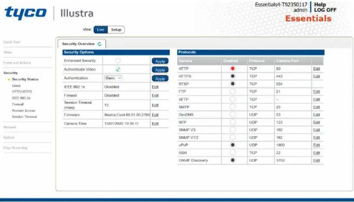
The Event Menu provides access to the following camera settings and functions:
- Security Status
- Users
- HTTP/HTTPS
- IEEE 802.1x
- Firewall
- Remote Access
- Session Timeout
Security Status
This section explains how to configure security features for the camera and modify the communication protocols that are used.
Enhanced Security
When you first log in to the Web User Interface, an overlay over the Live menu tab appears prompting you to choose either Standard or Enhanced Security mode. For more information regarding the requirements for Enhanced Security mode, refer to Summary of Security Modes on page 28.
Admin users can change the Security Mode of the camera from Standard Security to Enhanced Security.
Procedure 76 Enable Enhanced Security
Step Action
1 Select Setup on the Web User Interface banner to display the setup menus.
2 Select Security Status from the Security menu.
3 Select the Security Overview tab.
4 Check the Enable Enhanced Security check box and then the Apply button to enable enhanced security.
A prompt appears asking you for your current password and the new password for the Enchanced Security feature. Your password must adhere to the minimum requirements for an Enhanced Security password as seen below.
OR
Clear the Enable Enhanced Security check box to disable enhanced security.
Enhanced Security is disabled by default.
The Security Warning dialog appears.
5 Enter the current password in the Current Password text box.
6 Enter the New Username in the New Username text box.
7 Enter the new password in the New Password text box.
The password for enhanced security must meet the following requirements:
- Be a minimum of eight characters long
- Have at least one character from each of the following character groups:
Upper-case letters
Lower-case letters
Numeric characters
Special characters
8 Re-enter the new password in the Confirm Password text box.
9 Click Apply.
- End -
Procedure 77 Disable Enhanced Security Mode
Step Action
1 Select Setup on the Web User Interface banner to display the setup menus.
2 Select Security Status from the Security menu.
3 Select the Security Overview tab.
Note: When in Enhanced Security mode, changing the security mode requires the admin account password.
4 Click Apply.
- End -
Security Status
This section summarizes the communication protocols that are used and their status. The following communication protocols can be enabled: HTTP, FTP, Dyn DNS, SMTP, HTTPS, SNMP V1/2, SNMP V3, uPNP, and SFTP.
Security Overview
Procedure 78 Enable/Disable Communication Protocols
Step Action
1 Select Setup on the Web User Interface banner to display the setup menus.
2 Select Security Status from the Security menu.
3 Select the Security Overview tab.
4 Select the Edit button to configure the Protocol.
Note:
When in Enhanced Security, enabling/disabling individual protocols requires the admin account password.
Users
In this section you are able to add a user, change a user password and a delete user account. There are three levels of access: admin, operator and user.
Refer to Appendix A: User Account Access on page 100 for details on the features which are available to each role.
Note: The default Username is admin and the default Password is admin. To maintain security the password on the admin account is required to be changed on first log in.
View Current User Accounts
View a list of the current user accounts assigned to the camera.
Procedure 79 View User Accounts
Step Action
1 Select Setup on the Web User Interface banner to display the setup menus.
2 Select Users from the Security menu.
The current user accounts assigned to the camera display.
- End -
Add User
Add a new user account to allow access to the camera.
Procedure 80 Add a User
Step Action
1 Select Setup on the Web User Interface banner to display the setup menus.
2 Select Users from the Security menu.
3 Select the Add User tab.
4 Enter a User Name in the Name text box.
The username must start with a letter and can be followed by any alphanumeric values (a-z, A-Z, 0-9) and the following special characters, underscore(_, dash(-), or dot(.)
5 Select a Role:
- admin
- operator
- user
Refer to Appendix A: User Account Access for details on the features which are available to each role.
6 Enter a password in the Password text box.
The password for Standard Security must start with an alphanumeric character and is case sensitive, it can contain alphanumeric characters with a length of between 5 and 32 characters.
The password for enhanced security must meet the following requirements:
- Be a minimum of eight characters long.
- The password cannot contain the username.
- Have at least one character from each of the following character groups:
• Upper-case letters - ABCDEFGHIJKLMNOPQRSTUVWXYZ - Lower-case letters - abcdefghijklmnopqrstuvwxyz
- Numeric characters - 0123456789
- Special characters - @ % + \ / '! # \$^ ? : , () {} [] \~ - _
7 Enter the same password in the Confirm Password text box.
8 Select Apply to save the settings.
The new user account appears in the Users list on the Users tab.
Changing the User Accounts Password
Change the password of an existing user account.
Procedure 81 Change User Password
Step Action
1 Select Setup on the Web User Interface banner to display the setup menus.
2 Select Users from the Security menu.
3 Select the Change Password tab.
4 Select the user account from the Name drop-down menu.
5 Enter the current password for the user account in the Current Password text box.
6 Enter the new password for the user account in the New Password text box.
The password is case sensitive and can contain alphanumeric characters with a length of between 5 and 32 characters.
7 Enter the same new password in the Confirm New Password text box.
8 Select Apply to save the settings.
- End -
Delete a User Account
Delete a user account from the camera.
Note: The default 'admin' account cannot be deleted.
Procedure 82 Delete a User Account
Step Action
1 Select Setup on the Web User Interface banner to display the setup menus.
2 Select Users from the Security menu.
The Users tab displays.
3 Select to delete the corresponding user account.
You will be prompted to confirm the deletion.
4 Select OK to delete.
OR
5 Select Cancel.
- End -
HTTP / HTTPS
User can select the option to use HTTP, HTTPS or both. The camera automatically creates an SSL certificate file to use for HTTPS. It is possible to upload a custom SSL certificate if validation is
required.
Procedure 83 Specify HTTP Method
Step Action
1 Select Setup on the Web User Interface banner to display the setup menus.
2 Select HTTP/HTTPS from the Security menu.
3 Select the HTTP Method using the radio buttons
- HTTP
- HTTPS
- Both
- End -
Procedure 84 Add a HTTPS Certificate
Step Action
1 Select Setup on the Web User Interface banner to display the setup menus.
2 Select HTTP/HTTPS from the Security menu.
3 Click on the Upload button and navigate to the certificate location.
4 Select the file and select Open.
Note: The camera only accepts .pem format certificates. The certificate must have the server certificate and private key combined and the private key must not be password protected.
After the certificate has been uploaded the camera must be rebooted to take affect.
- End -
Delete a HTTPS Certificate
If you delete the existing certificate it will be replaced by a temporary substitute. The current browser session will be lost and you will be required to log back in to the camera Web User Interface.
Procedure 85 Delete a HTTPS Certificate
Step Action
1 Select Setup on the Web User Interface banner to display the setup menus.
2 Select HTTP/HTTPS from the Security menu.
3 Select Delete.
The camera displays a “Restarting HTTPS Service” page with a progress bar showing the deletion progress.
4 When complete, the camera returns to the log in page.
- End -
IEEE 802.1x
The IEEE 802.1x security feature provides port based network access control i.e. securing corporate networks from the attachment of unauthorized devices.
Authentication is carried out through use of the Extensible Authentication Protocol or EAP. Both PEAP and TLS methods are supported.
Procedure 86 Configure IEEE 802.1x Security
| Step | Action |
| 1 | Select Setup on the Web User Interface banner to display the setup menus. |
| 2 | Select IEEE 802.1x from the Security menu.The EAP Settings tab displays. |
| 3 | Select the Enable IEEE802.1x check box to enable IEEE802.1x security.OR |
| 4 | Clear the Enable IEEE802.1x check box to disable IEEE802.1x security. |
| 5 | Select the EAPOL Version from the drop-down menu. |
| 6 | Select the EAP Method using the radio buttons. |
| 7 | Enter the EAP identity name in the EAP Identify textbox. |
| 8 | Select Upload to navigate to the CA Certificate location. The Choose file dialog displays. |
| 9 | Navigate to the location where the certificate has been saved. Select the file and select Open. |
| 10 | Select Upload. The upload process starts. |
| 11 | If PEAP is selected:a Enter the required PEAP Password.ORIf TLS is selected -a Select Upload to navigate to the Client Certificate location.The Choose file dialog will be displayed.b Navigate to the location where the certificate has been saved.c Select the file and select Open.d Select Upload. The upload process starts.e Enter the required Private Key Password. |
- End -
Firewall
Configure the Basic Filtering and Address Filtering for the firewall.
Basic Filtering
Enable or disable basic filtering for the camera this includes:
- ICMP (Internet Control Message Protocol) Blocking
- RP (Reverse Path) Filtering
Procedure 87 Enable/Disable Basic Filtering
Step Action
1 Select Setup on the Web User Interface banner to display the setup menus.
2 Select Firewall from the Security menu.
The Basic Filtering tab displays.
3 Select the ICMP Blocking check box to enable ICMP blocking.
OR
Clear the ICMP Blocking check box to disable ICMP blocking. The default setting is 'Disabled'.
4 Select the RP Filtering check box to enable the RP filtering.
OR
Deselect the RP Filtering check box to disable.
The default setting is 'Disabled'.
- End -
Address Filtering
Configure the IP or MAC addresses which are denied access to the camera.
Procedure 88 Enable/Disable and configure Address Filtering
Step Action
1 Select Setup on the Web User Interface banner to display the setup menus.
2 Select Firewall from the Security menu.
3 Select the Address Filtering tab.
4 Select Off to disable address filtering completely.
OR
Select Allow to allow address filtering for specified addresses
OR
Select Deny to deny address filtering for specific addresses.
The default setting is 'Off'.
5 If address filtering has been set to Allow or Deny:
a Enter an IP or MAC Address to allow / deny in the IP or MAC Address text box in the following format xxx.xxx.xxx.xxx.
Note: CIDR (Classless Inter-Domain Routing) is supported when using address filtering. If using a CIDR address use the following format xxx.xxx.xxx.xxx/xx.
b Select Add.
6 Select Apply to save the settings.
Editing an Address Filter
Edit an existing address filter.
Procedure 89 Edit an Address Filter
Step Action
1 Select Setup on the Web User Interface banner to display the setup menus.
2 Select Firewall from the Security menu.
3 Select the Address Filtering tab.
4 Edit the IP or MAC Address in the IP or MAC Address text box.
5 Select Add to save the changes.
Deleting an Address Filter
Delete an existing address filter.
Procedure 90 Delete an Address Filter
Step Action
1 Select Setup on the Web User Interface banner to display the setup menus.
2 Select Firewall from the Security menu.
3 Select the Address Filtering tab.
4 Select to delete the corresponding address filter.
Remote Access
SSH Enable
Enables Secure Shell access into the camera, if remote access is permitted by the camera network. This will also enable Tyco Security Products Level 3 Technical Support to diagnose any problems on the camera.
Note: It is recommended to keep SSH Enable disabled. This function should only be enabled this when it is requested by Tyco Security Products Level 3 Technical Support.
Procedure 91 Configure SSH
Step Action
1 Select Setup on the Web User Interface banner to display the setup menus.
2 Select Remote Access from the Security menu.
The Remote Access tab displays.
3 Select the SSH Enable check box to enable SSH.
OR
Deselect SSH Enable check box to disable SSH.
The default setting is 'Disabled'.
- End -
ONVIF
The Web User Interface allows ONVIF functionality to be managed at a high level. ONVIF Discovery Mode and User Authentication can be enabled or disabled.
- ONVIF Discovery Mode allows enabling or disabling discovery of the camera via ONVIF.
- ONVIF User Authentication allows the camera to accept ONVIF commands from all users or only authenticated users. Enabling User Authentication ensures the camera will only execute commands from authenticated users.
The separation of Discovery Mode and User Authentication allows the camera to be set up in a configuration that suits requirements for the network and users. The preferred discovery method for the camera is Illustra Connect, and this utilizes ONVIF discovery. It is therefore recommended that ONVIF Discovery Mode is always enabled.
ONVIF Discovery Mode
Enable or disable ONVIF discovery on the camera.
Procedure 92 Enable/Disable ONVIF Discovery Mode
| Step | Action |
| 1 | Select Setup on the Web User Interface banner to display the setup menus. |
| 2 | Select Remote Access from the Security menu.The Remote Access tab displays. |
| 3 | Select the ONVIF Discovery Mode check box to enable ONVIF Discovery Mode.ORDeselect ONVIF Discovery Mode check box to disable ONVIF Discovery Mode.The default setting is ‘Enabled’. |
| - End - | |
ONVIF User Authentication
To utilize ONVIF User Authentication, there must be at least one admin level user in the ONVIF service.
Note: When in Enhanced Security mode, editing ONVIF User Authentication requires the admin account password.
Procedure 93 Enable/Disable ONVIF User Authentication
| Step | Action |
| 1 | Select Setup on the Web User Interface banner to display the setup menus. |
| 2 | Select Remote Access from the Security menu. |
The Remote Access tab displays.
3 Select the ONVIF User Authentication check box to enable ONVIF User Authentication.
OR
Deselect ONVIF User Authentication check box to disable ONVIF User Authentication.
The default setting is 'Enabled'.
- End -
UPnP Discovery
Enable or disable UPnP Discovery on the camera.
Procedure 94 Enable/Disable UPnP Discovery
Step Action
1 Select Setup on the Web User Interface banner to display the setup menus.
2 Select Remote Access from the Security menu.
The Remote Access tab displays.
3 Select the UPnP Discovery check box to enable UPnP Discovery.
OR
Deselect UPnP Discoverycheck box to disable UPnP Discovery.
The default setting is 'Enabled'.
- End -
Session Timeout
Session timeout specifies the number of minutes that a web session can remain idle before it is automatically terminated.
Procedure 95 Set a Session Timeout time
Step Action
1 Select Setup on the Web User Interface banner to display the setup menus.
2 Select Session Timeout from the Security menu. The Session Timeout tab displays.
3 Use the slider bar to select the Session Timeout (mins). The default setting is 15 minutes.
- End -
Network Menu
When you select the Network menu, the TCP/IP page displays, as seen in Figure 35 on page 82.
Figure 35 Network Menu
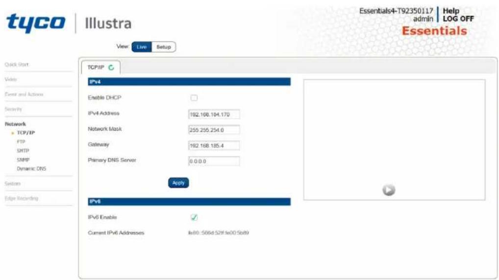
The Network Menu provides access to the following camera settings and functions:
- TCP/IP
- FTP
- SMTP
• SNMP
- Dynamic DNS
TCP/IP
Configure the IPv4 and IPv6 settings on the camera.
IPv4
Configure the IPv4 settings for the camera.
Note: When you perform a factory reset or reboot the unit searches for the last known IP address. If this is not available it reverts to the default IP address of 192.168.1.168. This could result duplicate IP addresses. Refer to Network Menu on page 82 for more information.
Procedure 96 Configure the IPv4 Settings
Step Action
1 Select Setup on the Web User Interface banner to display the setup menus.
2 Select TCP/IP from the Network menu.
3 Select the Enable DHCP check box to enable DHCP and disable manual settings. OR
Deselect Enable DHCP to disable DHCP and allow manual settings to be entered.
The default setting is 'Disabled'.
4 If Enable DHCP has been disabled:
a Enter the IPv4 Address in the IPv4 Address text box in the form xxx.xxx.xxx.xxx. The default setting is '192.168.1.168'
b Enter the Network Mask in the Network Mask text box xxx.xxx.xxx.xxx.
The default setting is '255.255.255.0'
c Enter the Gateway IP address in Gateway text box xxx.xxx.xxx.xxx.
d Enter the Primary DNS Server in the Primary DNS Server text box xxx.xxx.xxx.xxx.
5 Select Apply to save the settings.
- End -
IPv6
Enable IPv6 on the camera.
Procedure 97 Enable/Disable IPv6
Step Action
1 Select Setup on the Web User Interface banner to display the setup menus.
2 Select TCP/IP from the Network menu.
3 Select the IPv6 Enable check box to enable IPv6 on the camera.
OR
Deselect the IPv6 Enable check box to disable IPv6 on the camera.
The default setting is 'Enabled'.
If IPv6 is enabled the Link Local and DHCP address displays beside 'Current IPv6 Addresses' if available.
- End -
FTP
Configure the FTP settings for the FTP server. This is required to send video files from triggered analytic alerts. FTP must be configured to enable FTP video alerts when using analytics.
Note: FTP settings can also be configured in the Network menu.
Procedure 98 Configure FTP Server Settings
Step Action
1 Select Setup on the Web User Interface banner to display the setup menus.
2 Select FTP from the Network menu.
3 Select the Enable check box to enable FTP.
OR
Deselect the Enable check box to disable FTP.
The default setting is 'Enabled'.
Note: When in Enhanced Security mode, enabling FTP requires the admin account password.
4 If required, select the Secure FTP checkbox.
The default setting is 'Disabled'.
5 Enter the IP address of the FTP Server in the FTP Server text box.
6 Enter the FTP port in the FTP Port text box.
The default setting is 21.
7 Enter the FTP username in the Username text box.
8 Enter the FTP password in the Password text box.
9 Enter the FTP upload path in the Upload Path text box.
Note: When entering the upload path the following format should be used '/// of ftp directory>/
- End -
File Transfer Rate
You can limit the File Transfer Rate and assign a max transfer rate assigned to manage the amount of FTP bandwidth used.
Procedure 99 Configure the FTP Transfer Rate
Step Action
1 Select Setup on the Web User Interface banner to display the setup menus.
2 Select FTP from the Network menu.
3 Select the FTP tab.
4 Select the Limit Transfer Rate check box to limit the FTP transfer rate.
OR
Clear the Limit Transfer Rate check box to disable limited FTP transfer.
The default setting is 'Enabled'.
5 Enter the Max Transfer Rate in the Max Transfer Rate (Kbps) textbox.
The default setting is 50.
- End -
Test FTP Settings
Test the FTP settings that have been configured correctly.
Procedure 100 Test the FTP Settings
Step Action
1 Select Setup on the Web User Interface banner to display the setup menus.
2 Select FTP from the Network menu.
3 Select Test. A sample text file will be sent to the specified FTP destination to confirm that FTP settings are correct.
- End -
SMTP
Configure the SMTP settings to allow e-mail alerts to be sent from the camera when an analytic alert is triggered.
Note: SMTP settings must be configured to enable email alerts when using analytics.
Procedure 101 Configure SMTP Settings
Step Action
1 Select Setup on the Web User Interface banner to display the setup menus.
2 Select SMTP from the Network menu.
The SMTP tab displays.
3 Check the Enable SMTP check box to enable SMTP. Text boxes on the tab become available for entry.
Note: When in Enhanced Security mode, enabling SMTP requires the admin account password.
4 Enter the IP Address of the mail server in the Mail Server text box.
5 Enter the server port in the Server Port text box.
The default setting is '25'.
6 Enter the from email address in the From Address text box.
7 Enter the email address to send email alerts to in the Send Email to text box.
8 Select the Use authentication to log on to server check box to allow authentication details to be entered.
OR
Clear the Use authentication to log on to server to disable authentication.
The default setting is 'Disabled'.
9 If 'Use authentication to log on to server' check box has been selected:
a Enter the username for the SMTP account in the Username text box.
b Enter the password for the SMTP account in the Password text box.
10 Select Apply to save the settings.
- End -
Procedure 102 Test the SMTP Settings
Step Action
1 Select Setup on the Web User Interface banner to display the setup menus.
2 Select Event Settings from the Events and Actions menu.
3 Select the SMTP tab.
4 Select Test.
A sample text file is sent to the specified SMTP destination to confirm that SMTP settings are correct.
- End -
SNMP
The camera introduces support for the Simple Network Management Protocol making it easier to manage on an IP network.
The SNMP support includes support for V2 and V3. Using V2 means no authentication is required to access the data and results are unencrypted. V3 offers enhanced encryption and authentication security features.
Procedure 103 Configure SNMP Settings
Step Action
1 Select Setup on the Web User Interface banner to display the setup menus.
2 Select SNMP from the Network menu.
3 Enter a location reference in the Location text box.
4 Enter an SNMP managing contact reference in the Contact text box.
5 If using V2:
a Select the Enable V2 checkbox.
b Enter the authorized ID for reading SNMP data in the Read Community text box.
c Enter the Trap Community.
d Enter the Trap Address.
e Select Apply.
OR
If using V3:
a Select the Enable V3 checkbox.
b Enter the Read User.
c Select the Security Level from the drop down menu:
- noauth: No authentication / no encryption.
- auth: Authentication / no encryption. A user password is required. It is symmetrically encrypted using either MD5 or SHA.
- priv: Authentication / encryption. A user password is required as is symmetrically encrypted using either MD5 or SHA. A data encryption password is required as is symmetrically encrypted using either DES or AES.
d Select the Authentication Type using the radio buttons.
e Enter the Authentication Password
f Select the EncryptionType using the radio buttons.
g Enter the Encryption Password
h Select Apply.
- End -
Heartbeat
Procedure 104 Enable/Disable Heartbeat
Step Action
1 Select Setup on the Web User Interface banner to display the setup menus.
2 Select SNMP from the Network menu.
3 Select the Heartbeat tab.
4 Select the Enable Heartbeat check box to enable Heartbeat.
OR
Deselect the Enable Heartbeat check box to disable Heartbeat.
The default setting is 'Disabled'.
- End -
Procedure 105 Enable select Heartbeat intervals
Step Action
1 Select Setup on the Web User Interface banner to display the setup menus.
2 Select SNMP from the Network menu.
3 Select the Heartbeat tab.
4 Select the Enable Heartbeat check box to enable Heartbeat.
5 Use the slider bar to select the Heartbeat Interval (secs).
6 The default setting is '60' seconds. The seconds range from 5 to 500.
- End -
Dynamic DNS
Dynamic DNS is supported for updating, in real time a changing IP address on the Internet to provide a persistent domain name for a resource that may change location on the network. RFC 2136 Dynamic Updates in the Domain Name System. In this situation the camera talks only to the DHCP
server and the DHCP server is responsible for updating the DNS server. The camera sends its hostname to the DHCP server when requesting a new lease and the DHCP server updates the DNS records accordingly. This is suitable for an intranet style configuration where there is an internal DHCP and DNS service and the user wants only to access their camera within their own network.
By default, when making a DHCP request the camera transmits its hostname as part of the DHCP request. This option is not user configurable. The cameras hostname matches the configurable parameter "camera name" on the Web User Interface. Any DHCP request contains the cameras hostname for use of the DHCP server to forward to an appropriate DNS server.
Dynamic DNS
Configure the Dynamic DNS settings for the camera.
Procedure 106 Configure Dynamic DNS
Step Action
1 Select Setup on the Web User Interface banner to display the setup menus.
2 Select Dynamic DNS from the Network menu.
3 Select the Service Enable check box to enable Dynamic DNS.
OR
Deselect Service Enable check box to disable Dynamic DNS.
The default setting is 'Disabled'.
4 If Service Enable has been enabled:
a Enter the Camera Alias in the text box.
b Select a Service Provider from the drop-down list:
- dyndns.org
- easydns.com
- no-ip.com
- zerigo.com
- dynsip.org
- tzo.com
c Enter a Username in the text box.
d Enter a Password in the text box.
e Enter Service Data in the text box.
5 Select Apply to save the settings.
- End -
System
When you open the System menu, the Maintenance page appears, as seen in Figure 36 on page 89.
Figure 36 System Menu
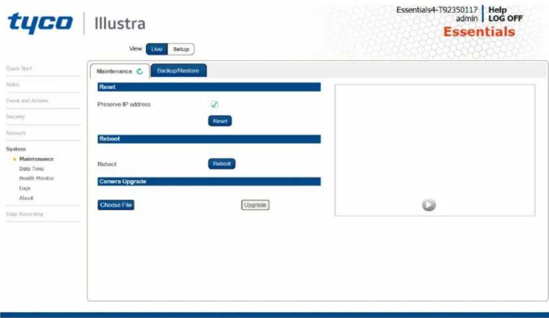
The System Menu provides access to the following camera settings and functions:
- Maintenance
- Date Time
• Health Monitor - Logs
- About
Maintenance
The Maintenance menu allows you to restore the camera settings to factory default, reboot the camera and apply a firmware upgrade.
Reset
To perform a physical reset of the camera, refer to the chapter regarding your camera model in this guide.
Note: Network settings can be retained if required.
Procedure 107 Resetting the Camera
Step Action
1 Select Setup on the Web User Interface banner to display the setup menus.
2 Select Maintenance from the System menu.
3 Select the Preserve IP address check box to retain the current network settings during the camera reset.
OR
Deselect the Preserve IP address check box to restore the default networking settings.
The default setting is 'Enabled'.
4 Select Reset.
You will be prompted to confirm the camera reset.
- Select OK to confirm. The Web User Interface will display a "Camera Resetting" page with a progress bar showing the reboot progress.
- When the camera is restarted it will take 2 - 3 minutes until it is online and ready to be accessed and controlled.
OR
Select Cancel.
5 The Log in page displays.
- End -
Reboot
To perform a physical reset of the camera, refer to the chapter regarding your camera model in this guide.
Procedure 108 Reboot the Camera
Step Action
1 Select Setup on the Web User Interface banner to display the setup menus.
2 Select Maintenance from the System menu.
3 Select Reboot.
You will be prompted to confirm the camera reboot.
4 Select OK to confirm.
The Web User Interface will display a “Camera Rebooting” page with a progress bar showing the reboot progress.
When the camera is restarted it will take 2 - 3 minutes until it is online and ready to be accessed and controlled.
OR
Select Cancel.
5 The Log in page displays.
- End -
Camera Firmware Upgrade
The camera can be upgraded using firmware provided by Illustra. Alternatively, the camera can also be upgraded using Illustra Connect. Refer to the Illustra Connect User Guide for further information.
Note: All existing camera settings are maintained when the firmware is upgraded.

Caution
You should only use firmware that has been provided by Illustra. Using any other firmware may cause a malfunction and damage the camera.
Procedure 109 Upgrade Camera Firmware
Step Action
1 Select Setup on the Web User Interface banner to display the setup menus.
2 Select Maintenance from the System menu.
3 Select Choose File.
The Choose file to Upload dialog displays.
4 Navigate to the location where the firmware file has been saved.
5 Select the firmware file then select the Open button.
6 Select Upgrade.
The file transfer will begin. Do not disconnect power to the camera during the upgrade process. The camera restarts automatically after the updates have been completed, this can take from 1 to 10 minutes. The Log in page displays.
- End -
Backup/Restore
Backup camera data and restore from a previously saved data file. The data file can be saved to a specified location and used to restore the camera configuration.
Note: A saved backup data file created on a camera is camera specific and cannot be used to restore the settings on a different camera.
Procedure 110 Backup Camera Data
Step Action
1 Select Setup on the Web User Interface banner to display the setup menus.
2 Select Maintenance from the System menu.
3 Select the Backup/Restore tab.
4 Select Backup. You are prompted to save the backup file.
5 Select Save.
- End -
Procedure 111 Restore Camera from Backup
Step Action
1 Select Setup on the Web User Interface banner to display the setup menus.
2 Select Maintenance from the System menu.
3 Select the Backup/Restore tab.
4 Select Choose File.
The Choose file to Upload dialog displays.
5 Navigate to the location where the firmware file has been saved.
6 Select the firmware file then select the Open button.
7 Select Upload.
The file transfer begins. Do not disconnect power to the camera during the upgrade process. The camera restarts automatically after the updates have been completed, this can take from 1 to 10 minutes. The Log in page displays.
- End -
Date / Time
Set the date and time on the camera.
Note:
Date and Time can also be configured in the Quick Start menu.
Procedure 112 Configuring the Date and Time
Step Action
1 Select Setup on the Web User Interface banner to display the setup menus.
2 Select the Date/Time from the Basic Configuration menu.
3 Select the Time 24-hour check box to enable the 24-hour clock.
Or
Deselect the Time 24-hour check box to enable the 12-hour clock.
The default setting is '24-hour'.
4 Select the Date Display Format from the drop-down menu:
- DD/MM/YYYY
- MM/DD/YYYY
- YYYY/MM/DD
The default setting is 'DD/MM/YYYY'.
5 Select the Time Zone from the drop-down menu.
The default setting is (GMT) GMT+0.
6 Select the Set Time setting by selecting the radio buttons:
- Manually
- via NTP
The default setting is 'Manually'.
7 If you select Manually in step 5:
a Select the Date (DD/MM/YYYY) using the drop-down menus.
b Select the Time (HH:MM:SS) using the drop-down menus.
8 If you select via NTP in step 5:
a Enter the NTP Server Name in the text box.
- End -
Health Monitor
The Health Monitor function provides visibility on the health status of popular device parameters. Each parameter can be enabled or disabled. The refresh frequency of the health monitor can be determined by selecting a duration from the Reporting Period drop-down menu.
Procedure 113 Configure Health Monitor Settings
Step Action
1 Select Setup on the Web User Interface banner to display the setup menus.
2 Select the Health Monitor from the System menu.
3 Select the Recording Period from the drop-down menu.
4 Select the corresponding check box to enable health monitoring on a parameter.
OR
Clear the corresponding check box to disable health monitoring on a parameter.
The default setting for all parameters is Enabled.
- End -
Logs
Information is provided on system logs created by the camera.
System Log
The system log gives the most recent messages from the unix/var/log/messages file. Information will include the following:
- Messages about system behavior such as process startup/shutdown.
- Warnings about recoverable problems that processes encounter.
- Error messages where processes encounter problems they cannot fix; note that this does not mean that the process will not continue to work, only that it encountered an issue it could do nothing about.
Procedure 114 Display System Log
| Step | Action |
| 1 | Select Setup on the Web User Interface banner to display the setup menus. |
| 2 | Select Logs from the System menu.The System Log tab displays. |
| 3 | Select Refresh to refresh the log for the most up-to-date information. |
| - End - | |
Procedure 115 System Log Filter
| Step | Action |
| 1 | Select Setup on the Web User Interface banner to display the setup menus. |
| 2 | Select Logs from the System menu.The System Log tab displays. |
| 3 | Enter the number of lines of the log file you would like to view in the Lines text box. |
| 4 | Enter the word or phrase that you would like to search for in the Filter text box. |
| 5 | Select Refresh to refresh the log for the most up-to-date information. |
| - End - | |
About
The About menu provides the following camera information:
- Camera Name
- Model
- Product Code
- Manufacturing Date
- Serial Number
- MAC Address
- Firmware Version
- Hardware Version
- iAPI Version
Procedure 116 Display Model Information
| Step | Action |
| 1 | Select Setup on the Web User Interface banner to display the setup menus. |
| 2 | Select About from the System menu. The model tab displays. |
| - End - | |
Procedure 117 Edit Camera Name
Step Action
1 Select Setup on the Web User Interface banner to display the setup menus.
2 Select About from the System menu. The model tab displays.
3 Edit the name in the Camera Name textbox.
- End -
Edge Recording
When you select the Edge Recording menu, the Micro SD Card Management page appears, as seen in Figure 37 on page 96.
Figure 37 Edge Recording Menu

The Edge Recording Menu provides access to the following camera settings and functions:
- Micro SD Card Management
- Record Settings
- Event Download
Micro SD Card Management
Edge recording provides the ability to save recorded video to a Micro SD Card. Video can be configured to be recorded based on an event. Without a Micro SD Card current faults notifications displayed on camera if an alarm is triggered. Using a Micro SD Card enables the following:
- Current faults notifications displayed on camera if an alarm is triggered.
• Video and screen shot are saved to the SD card. - SMTP notifications can be sent.
- FTP uploads of video can be sent.
Inserting the Micro SD Card
When inserting a Micro SD Card it is essential that the camera is rebooted. The Micro SD Card should be mounted and unmounted through the Web User Interface. If you receive a 'Device is Busy' model you should wait and try again in a few minutes. If this does not work then it may be necessary to disable Motion Detection, FTP or any other process which may be using the Micro SD Card.
Note: Refer to the Quick Reference Guide supplied with the product for details on how to remove the housing assembly and gain access to the camera.
Procedure 118 Insert the Micro SD Card by powering down the Camera
Step Action
1 Turn off the camera by disconnecting the power supply.
2 Insert the Micro SD card into the camera.
3 Reconnect the power supply and power up the camera.
- End -
Procedure 119 Mount the Micro SD Card through the Web User Interface reboot the Camera
Step Action
1 Insert the Micro SD card into the camera.
2 Select Setup on the Web User Interface banner to display the setup menus.
3 Select SD Card Management menu from the Edge Recording menu.
4 Select Mount.
- End -
Removing the Micro SD Card
If at any stage you need to remove the Micro SD card from the camera one of the following two procedures should be used:
- Remove the Micro SD Card by powering down the camera - Use this procedure if you do not have access to the Web User Interface and are unable to unmount the Micro SD card before removal.
- Unmount the Micro SD Card for Removal - Use this procedure when you are unable to access the power supply to the camera.
Note: Refer to the Quick Reference Guide supplied with the product for details on how to remove the housing assembly and gain access to the camera.
Procedure 120 Remove the Micro SD Card by powering down the Came
1 Turn off the camera by disconnecting the power supply.
2 Remove the Micro SD card from the camera.
Note: AVI clips are not available on the camera until the Micro SD card has been inserted and the camera rebooted.
3 Reconnect the power supply and power up the camera.
- End -
Procedure 121 Unmount the Micro SD Card for Removal
Step Action
1 Select Setup on the Web User Interface banner to display the setup menus.
2 Select SD Card Management menu from the Edge Recording menu.
3 Select Unmount.
You are prompted to confirm the unmounting.
4 Select OK to confirm.
OR
5 Select Cancel.
Remove the Micro SD card from the camera.
MP4 clips are not available on the camera until the Micro SD card has been inserted and mounted.
- End -
Record Settings
Select which video stream to use for alarm video and configure pre and post event durations for the playable video clip. The camera can record video generated from MD, face detection and events.
Procedure 122 Configure Record Settings
Step Action
1 Select Setup on the Web User Interface Banner to display the setup menus.
2 Select Record Settings from the Edge Recording menu.
3 Select Enable Record to allow the camera to create a playable video clip.
OR
Deselect Enable Record to disable the feature.
4 If Enable Record has been enabled:
a Select the required video stream from the Video drop-down menu.
Refer to Procedure 5-1 Configure the Video Stream Settings.
b Select the Post Event (secs) in seconds from the drop-down menu. Values range from 0 to 10.
The default setting is 5 seconds.
5 Select Apply to save.
- End -
Event Download
If an event action has record mode enabled, when triggered, the associated video is logged in the event download table where it can later be downloaded from an Micro SD Card using the specified upload protocol.
Note: An event action must have record mode enabled to be logged and downloaded. This is configured in Event Actions under the Events and Actions menu.
Appendix A: User Account Access
| Camera Menu Sub Menu Tab | Admin Operator | User | |||
| Live View Live View X X | |||||
| Quick Start | Basic Configuration | TCP/IP X | |||
| Video Stream Settings | X | X | |||
| Picture Basic X X | |||||
| Picture Additional X | X | ||||
| Date Time | X | ||||
| OSD | X X | ||||
| Video | Streams | Video Stream Settings | X | X | |
| Picture Settings | Picture Basic X X | ||||
| Picture Additional X | X | ||||
| Lens Calibration | X | ||||
| Date/Time/OSD | Date Time | X | |||
| OSD | X X | ||||
| Privacy Zones | Privacy Zones | X X | |||
| Events and Actions | Event Settings | SMTP | X | ||
| FTP | X | ||||
| Event Actions | Event Actions X | ||||
| Analytics | ROI | X | |||
| Motion Detection | X | ||||
| Blur Detection | X | ||||
| Event Logs | Event Log | X | |||
| Security | Security Status | Security Overview | X | ||
| Users | User | X | |||
| Add User | X | ||||
| Change Password | X X X | ||||
| HTTP/HTTPS | HTTP/HTTPS | X | |||
| IEEE 802.1x | EAP Settings X | ||||
| Firewall Basic Filtering X | |||||
| Address Filtering X | |||||
| Remote Access R | Remote Access | X | |||
| Session Timeout | Session Timeout X | ||||
| Network | TCP/IP | TCP/IP | X | ||
| FTP | FTP | X | |||
| SMTP | SMTP | X | |||
| SNMP | SNMP | X | |||
| Dynamic DNS | Dynamic DNS | X | |||
| System | Maintenance | Maintenance | X | ||
| Backup / Restore | X | ||||
| Date Time | Date Time | X | |||
| Health Monitor | Health Monitor | X | |||
| Logs | System Log | X | |||
| About | Model | X | X X | ||
| Edge Recording | SD Card Management | SD Card Management | X | ||
| Record Settings | Record Settings | X | |||
| Event Download | Event Download | X | |||
Appendix B: Using Media Player to View RTS Streaming
Note: This appendix is provided for user instruction only. Tyco Security Products does not support or is not responsible for any error caused during the use of third party software used for RTSP playback.
Procedure 123 Viewing RTSP Stream through Media Player
Step Action
You can use Media Player to view live video in real time from the camera.
1 Select Media then Open Network Stream.
2 Enter the IP address of the camera stream in the Network URL text box in the following format to view Stream 1 and 2:
- Stream 1: rtsp://cameraip:554/videoStreamId=1
- Stream 2: rtsp://cameraip:554/videoStreamId=2
For example: rtsp://192.168.1.168:554/videoStreamId=1
3 Select Play. The live video stream displays.
- End -
Appendix C: Stream Tables
Essentials Gen 4 - 2MP, Streaming Combinations
Table 38 on page 103 provide information for the stream resolutions and supported FPS of the Essentials Gen 4 2MP cameras herein.
Table 38 2MP Camera Stream Set A (all resolution, codes and frame rate combinations of Stream
| Normal Mode | |||||
| Resolution Description | Max FPS | ||||
| TWDR Off TWDR | |||||
| Stream 1 | h.264, h.265, MJPEG | 1920 x 1080 | (1080p) 16:9 | 30 | 30 |
| 1600 x 900 | (HD+) 16:9 | 30 | 30 | ||
| 1280 x 720 | (720p) 16:9 | 30 | 30 | ||
| 1024 x 576 | (PAL+) 16:9 | 30 | 30 | ||
| 960 x 540 | 16:9 | 30 | 30 | ||
| 800 x 480 | 16:9 | 30 | 30 | ||
| 640 x 360 | (mHD) 16:9 | 30 | 30 | ||
| 480 x 270 | 16:9 | 30 | 30 | ||
| 320 180 | 16:9 | 30 | 30 | ||
| Stream 2 | h.264, h.265, MJPEG | 1920 x 1080 | (1080p) 16:9 | 30 | 30 |
| 1600 x 900 | (HD+) 16:9 | 30 | 30 | ||
| 1280 x 720 | (720p) 16: 9 | 30 | 30 | ||
| 1024 x 576 | (PAL+) 16:9 | 30 | 30 | ||
| 960 x 540 | 16:9 | 30 | 30 | ||
| 800 x 480 | 16:9 | 30 | 30 | ||
| 640 x 360 | (m HD) 16:9 | 30 | 30 | ||
| 480 x 270 | 16:9 | 30 | 30 | ||
| 320 x 180 | 16:9 | 30 | 30 | ||
Note: A maximum of three concurrent streams are supported by the camera. This includes shared streams.
Appendix D: Camera Defaults
The below table details the defaults for the Illustra Connect Web User Interface.
Table 39 Camera Defaults
| Tab Item Default | |||||
| TCP/IP | |||||
| Enable DHCP ON | |||||
| IPv4 Address 192.168.1.168 | |||||
| Network Mask 255.255.255.0 | |||||
| Gateway Unspecified | |||||
| Primary DNS Unspecified | |||||
| IPv6 Enable ON | |||||
| Current IPv6 Address Unspecified | |||||
| Video Stream Settings | |||||
| Stream Number | 1 | 2 | |||
| Codec | H264 | H264 | |||
| Profile | Main | Main | |||
| 2MP Resolution | 1920x1080 | 1920x1080 | |||
| 2MP Frame Rate (fps) | 30 | 30 | |||
| 2MP GOP Length [1-150] | 30 | 30 | |||
| MJPEG Quality | N/A | N/A | |||
| Rate Control | CVBR | CVBR | |||
| VBR Quality | N/A | N/A | |||
| CVBR Max Bit Rate 2MP | 8000 | 8000 | |||
| CBR Bit Rate 2MP | 3000 | 3000 | |||
| Picture Basic | |||||
| Mirror OFF | |||||
| Flip OFF | |||||
| Focus Unspecified | |||||
| Zoom Unspecified | |||||
| Exposure Method Center Weighted | |||||
| Exposure Offset (F-stops) | 0 | ||||
| Min Exposure (sec) 1/10000 | |||||
| Max Exposure (sec) 1/8 | |||||
| Max Gain (dB) | 45dB | ||||
| Iris Level | 1 | ||||
| Frequency | 60Hz | ||||
| Flickerless | OFF | ||||
| Picture Additional | |||||
| Enable WDR | OFF | ||||
| Enable IR Illuminator | ON | ||||
| Day Night Mode | Auto Mid | ||||
| Brightness | 50% | ||||
| Contrast | 50% | ||||
| Saturation | 50% | ||||
| Sharpness | 50% | ||||
| White Balance Mode | Auto Wide | ||||
| Red | Scene dependent | ||||
| Blue | Scene dependent | ||||
| Date/Time/OSD | |||||
| Camera Friendly Name | Essential4 - SERIALNUMBER | ||||
| Camera Time Unspecified | |||||
| Time 24-hour ON | |||||
| Date Display Format YYYY/MM/DD | |||||
| Time Zone (GMT) GMT +0 | |||||
| Set Time Manually | |||||
| Date(DD/MM/YY) Unspecified | |||||
| Time(HH:MM:SS) Unspecified | |||||
| Text size Normal | |||||
| OSD Name OFF | |||||
| OSD Time | OFF | ||||
| OSD User defined | Unspecified | ||||
| Privacy Zones | |||||
| Name | Unspecified | ||||
| SMTP | |||||
| Mail Server | Unspecified | ||||
| Server Port 25 | |||||
| From Address | Unspecified | ||||
| Send Email To | Unspecified | ||||
| Use authentication to log on to server | OFF | ||||
| FTP | |||||
| Enable FTP | ON | ||||
| FTP Server | Unspecified | ||||
| FTP Port | 21 | ||||
| Username | Unspecified | ||||
| Password | Unspecified | ||||
| Upload Path Unspecified | |||||
| Limit Transfer Rate ON | |||||
| Max Transfer Rate (Kbps) | 50 | ||||
| Event Actions | |||||
| Fault action 1 | Unspecified | ||||
| Fault action 2 | Unspecified | ||||
| Fault action 3 | Unspecified | ||||
| Fault action 4 | Unspecified | ||||
| Fault action 5 | Unspecified | ||||
| ROI | |||||
| Table Unspecified | |||||
| Action Unspecified | |||||
| Motion Detection | |||||
| Enable Motion Detection | OFF | ||||
| Sensitivity HIGH | |||||
| Action Unspecified | |||||
| Blur Detection | |||||
| Enable Blur Detection | OFF | ||||
| Event Log Unspecified | |||||
| Security | |||||
| Security Status | Standard | ||||
| Enhanced Security Disabled | |||||
| Authenticate Video | Enabled | ||||
| Authentication | Basic | ||||
| Users | |||||
| Logon Name Admin | |||||
| Role Admin | |||||
| Add User | |||||
| Name Unspecified | |||||
| Role Unspecified | |||||
| Password Unspecified | |||||
| Confirm Password Unspecified | |||||
| Change Password | |||||
| Name Unspecified | |||||
| Current Password Unspecified | |||||
| New Password Unspecified | |||||
| Confirm New Password | Unspecified | ||||
| HTTP/HTTPS | |||||
| HTTP Method BOTH | |||||
| Select Certificate File | Unspecified | ||||
| EAP Settings | |||||
| Enable IEEE802.1x | OFF | ||||
| EAPOL Version | 1 | ||||
| EAP Method | PEAP | ||||
| EAP Identity | Unspecified | ||||
| CA Certificate Unspecified | |||||
| Password Unspecified | |||||
| Client Certificate | Unspecified | ||||
| Private Key Password | Unspecified | ||||
| Basic Filtering | |||||
| ICMP Blocking OFF | |||||
| Rp Filtering OFF | |||||
| SYN Cookie Verification | OFF | ||||
| Address Filtering | |||||
| Filtering OFF | |||||
| IP or MAC Address Unspecified | |||||
| Remote Access | |||||
| SSH Enable OFF | |||||
| ONVIF Discovery Mode | ON | ||||
| ONVIF User Authentication | ON | ||||
| UPnP Discovery ON | |||||
| Session Timeout | |||||
| Session Timeout (mins) | 15 | ||||
| Dynamic DNS | |||||
| Service Enable OFF | |||||
| Camera Alias | Unspecified | ||||
| Service Provider | dyndns.org | ||||
| Username | Unspecified | ||||
| Password | Unspecified | ||||
| Service Data | Unspecified | ||||
| Maintenance | |||||
| Preserve IP Address | ON | ||||
| Select Firmware Image File | Unspecified | ||||
| Date Time | |||||
| Camera Time | |||||
| Time 24-hour ON | |||||
| Date Display Format YYYY/MM/DD | |||||
| Time Zone Unspecified | |||||
| Set Time Unspecified | |||||
| NTP Server Name Unspecified | |||||
| Backup/Restore | |||||
| Select Saved Data File | Unspecified | ||||
| Health Monitor | |||||
| Reporting Period (seconds) | 60 | ||||
| Health Monitor Table Unspecified | |||||
| System Log | |||||
| Lines (From The End Of The Log File) | Unspecified | ||||
| Filter (Only Lines Containing Text) | Unspecified | ||||
| Model | |||||
| Camera Name Factory | configuration | ||||
| Model | Factory configuration | ||||
| Product Code | Factory configuration | ||||
| Manufacturing Date | Factory configuration | ||||
| Serial Number | Factory configuration | ||||
| MAC Address | Factory configuration | ||||
| Firmware Version | Factory configuration | ||||
| Hardware Version Factory configuration | |||||
| SD Card Management | |||||
| Disk Unspecified | |||||
| File Type Unspecified | |||||
| Total Size Unspecified | |||||
| Free Space Unspecified | |||||
| Status Unspecified | |||||
| Record Settings | |||||
| Enable Even Recording | OFF | ||||
| Record Source Stream | 1 | ||||
| Pre Event (secs) 10 | |||||
| Post Event (secs) 10 | |||||
| Event Download | |||||
| File Name Table | Unspecified | ||||
Appendix E: Technical Specifications
The table below lists technical specifications of the Illustra Essentials Gen 4 2MP Dome cameras.
| General Features | ||
| Model Type | 2MP Fixed Dome camera 2MP VF Dome camera | |
| Model No. | IES02-D10-OI04 IES02-D12-OI04 | |
| Camera Body Color | RAL 9003 - Signal White RAL 9003 - | Signal White |
| Vandal Resistant Rating | IK10 IK10 | |
| Mechanical Features | ||
| Dimensions | ∅110 x 82 mm(∅4.33in x 3.29in) ∅124 x 113mm(∅4.88in x 4.45in) | |
| Weight | 0.53kg (1.16 lb.) 0.65kg (1.43 lb.) | |
| Pan Rotation Angle | 355° | 355° |
| Tilt Angle | 70° | 70° |
| Z-axis Rotation | 355° | 355° |
| Housing Material | Aluminum Alloy (ADC 12) | Aluminum Alloy (ADC 12) |
| Bubble | PC (S3000UR) | PC (S3000UR) |
| Other Housing Material | PC (141R)Silicon (TSE2183U) | PC (141R)Silicon (TSE2183U) |
| Video Processor | ||
| ROM/Flash Size | 256 Mbytes | 256 Mbytes |
| RAM Size | 512 Mbytes | 512 Mbytes |
| RTC Hold Up Time | 24 hours | 24 hours |
| Image Sensor | ||
| Format | 1/2.8" CMOS | 1/2.8" CMOS |
| Capture Method | Rolling | Rolling |
| Scan Method | Progressive | Progressive |
| Lens | ||
| Design Type | 2 glasses, 3 plastics | 6 groups, 9 elements |
| Aperture Range | f 1.8 f 1.4 - 2.8 | |
| Focal Length Range | f 2.8mm f 2.7-13.5mm | |
| Focal Means Fixed | Motorized | |
| Focal Type Fixed | Varifocal | |
| Focus Type Fixed | Motorized | |
| Auto Focus N/A | One-Touch / Manual | |
| IR Correction Optical corrected | Optical corrected | |
| Day/Night | True D/N with ICR | True D/N with ICR |
| Horizontal Angle of View | 112° | 105° (Wide); 30° (Tele) |
| Vertical Angle of View | 60° | 75° (Wide); 22° (Tele) |
| Format | 1 / 2.7" | 1 / 2.7" |
| Illuminator | ||
| Wavelength | 850 mm | 850 mm |
| IR Distance 25m | range IR 30m range IR | |
| Smart IR | Yes | Yes |
| Adaptive IR N/A | N/A | |
| Power Supply | ||
| Power Requirement | Power over Ethernet (PoE) IEEE 802.3af Type 1 Class 3DC 12V | Power over Ethernet (PoE) IEEE 802.3af Type 1 Class 3DC 12V |
| Current Draw Amps | PoE = 0.15ADC 12V = 0.6A | PoE = 0.2ADC 12V = 0.82A |
| Wattage | PoE = 7.2WDC 12V = 7.3W | PoE = 9.7WDC 12V = 9.9W |
| Line Frequency Range | N/A N/A | |
| 12V DC range | -10% +10% | -10% +10% |
| Video Codecs | ||
| Frame Rate Range | 1 to 30 fps | 1 to 30 fps |
| Maximum Resolution and Rate | 1920 x 1080 @ 30 fps | 1920 x 1080 @ 30 fps |
| Video Imaging | ||
| Dynamic Range Method | Digital WDR, True WDR Digital WDR, | True WDR |
| I/O Interfaces | ||
| Micro SD Card | Micro SD & SDXC slot up to 256GB; Class 10 or higher; Card not included | Micro SD & SDXC slot up to 256GB; Class 10 or higher; Card not included |
| Alarm Inputs | N/A N/A | |
| Auxiliary Outputs | N/A N/A | |
| Video Output | N/A N/A | |
| IP Connector RJ | 45 RJ-45 | |
| LED Indicators | Power (Red), Network communication (Green) | Power (Red), Network communication (Green) |
| Reset Buttons | RebootReturn to defaults | RebootReturn to defaults |
| Environmental | ||
| Operating Temperature Range | -30° to +55°C (-22° to +131°F) -30° to +55°C (-22° to +131°F) | |
| Start-up Temperature Range | -20° to +55°C (-4° to +131°F) -20° to +55°C (-4° to +131°F) | |
| Water/Dust Intrusion | IP67 IP67 | |
| Client Interfaces | ||
| Browsers supported | IE 9 or above, Firefox, Safari, Chrome | IE 9 or above, Firefox, Safari, Chrome |
| Networking | ||
| Languages supported | English (default), Arabic, Czech, Danish, German, Spanish, French, Hungarian, Italian, Korean, Japanese, Netherlands, Polish, Portuguese, Swedish, Turkish, Chinese Traditional, Chinese Simplified, Russian, Hindi. | English (default), Arabic, Czech, Danish, German, Spanish, French, Hungarian, Italian, Korean, Japanese, Netherlands, Polish, Portuguese, Swedish, Turkish, Chinese Traditional, Chinese Simplified, Russian, Hindi. |
| Ethernet 10/100 | Base-T 10/100 | Base-T |
| Supported Protocols | TCP/IP, IPv4, IPv6, TCP, UDP, HTTP, FTP, DHCP, WS-Discovery, DNS, DDNS, RTP, TLS, Unicast, NTP, SMTP, WSSecurity, IEEE 802.1x, PEAP, SSH, HTTPS, SSL, SOAP, WSAddressing, SNMP, UPnP, RTSP, LLDP | TCP/IP, IPv4, IPv6, TCP, UDP, HTTP, FTP, DHCP, WS-Discovery, DNS, DDNS, RTP, TLS, Unicast, NTP, SMTP, WSSecurity, IEEE 802.1x, PEAP, SSH, HTTPS, SSL, SOAP, WSAddressing, SNMP, UPnP, RTSP, LLDP |
| Base Protocol | TCP/IP - RFC4614 | TCP/IP - RFC4614 |
| Internet LayerAddressing | IPv4 - RFC791IPv6 - RFC2460 | IPv4 - RFC791IPv6 - RFC2460 |
| Transport Layer | TCP - RFC973UDP - RFC768 | TCP - RFC973UDP - RFC768 |
| DataTransmission | HTTP/HTTPS - RFC2616FTP - RFC959 | HTTP/HTTPS - RFC2616FTP - RFC959 |
| NetworkAddressConfiguration | DHCP - RFC2131 Zeroconf -RFC3927Static IP addressLLDP | DHCP - RFC2131 Zeroconf - RFC3927Static IP addressLLDP |
| TimeSynchronization | NTP - RFC1305IETF NTP Working Groupi minute poll rate | NTP - RFC1305IETF NTP Working Groupi minute poll rate |
| SMTP - RFC5321Authenticated SMTP - RFC4954 | SMTP - RFC5321Authenticated SMTP - RFC4954 | |
| Authenticationand Security | IEEE.802.1x - TLS/PEAPHTTPS (HTTP over TLS) - RFC2818WS-SecurityMulti-level password protectionIP address filteringHTTPS encryptionUser access log | IEEE.802.1x - TLS/PEAPHTTPS (HTTP over TLS) - RFC2818WS-SecurityMulti-level password protectionIP address filteringHTTPS encryptionUser access log |
| Streaming | RTP - RFC3550RTSP - RFC2326Unicast Streaming | RTP - RFC3550RTSP - RFC2326Unicast Streaming |
| FirmwareUpgrade | Browser/illustra Connect/ONVIF Browser/illustra Connect/ONVIF | |
| General Features | ||
| Model Type 2MP | Fixed Bullet camera 2MP VF Bullet camera | |
| Model No. IES02 | B10-BI04 IES02-B12-BI04 | |
| Camera Body Color | RAL 9003 - Signal White RAL 9003 | Signal White |
| Vandal Resistant Rating | Front: IK07Body: IK08 | Front: IK07Body: IK08 |
| Mechanical Features | ||
| Dimensions 77x84 | 4x147mm(3.03in x 3.3in x 5.78in) 77x84 | 4x176mm(3.03in x 3.3in x 6.92in) |
| Weight 0.49kg (1.08 lb) | 0.58kg (1.28lb) | |
| Pan Rotation Angle | 360° | 360° |
| Tilt Angle | 90° | 90° |
| Z-axis Rotation | N/A | N/A |
| Housing Material | PC (L-1250Z) | PC (L-1250Z) |
| Bracket Material | PC (L-1250Z) | PC (L-1250Z) |
| Other Housing Material | PC (S-3000UR) (L-1225Z)Silicon (TSE2183U) (KE-951U) | PC (S-3000UR) (L-1225Z)Silicon (TSE2183U) (KE-951U) |
| Video Processor | ||
| ROM/Flash Size | 256 Mbytes | 256 Mbytes |
| RAM Size | 512 Mbytes | 512 Mbytes |
| RTC Hold Up Time | 24 hours | 24 hours |
| Image Sensor | ||
| Format 1/2.8" CMOS | 1/2.8" CMOS | |
| Capture Method | Rolling | Rolling |
| Scan Method | Progressive | Progressive |
| Lens | ||
| Design Type | 2 glasses, 3 plastics | 6 groups, 9 elements |
| Mount | 14mm | 14mm |
| Aperture Range | F 1.8 | F 1.4 – 2.8 |
| Focal Length Range | F 2.8mm | F 2.7-13.5mm |
| Focal Means Fixed Motorized | ||
| Focal Type Fixed | Varifocal | |
| Focus Type Fixed Motorized | ||
| Auto Focus N/A | One-Touch / Manual | |
| IR Correction Optical corrected Optical corrected | ||
| Day/Night True D | D/N with ICR True | D/N with ICR |
| Horizontal Angle of View | 112° | 105° (Wide); 30° (Tele) |
| Vertical Angle of View | 60° | 75° (Wide); 22° (Tele) |
| Format | 1 / 2.7 | 1 / 2.7 |
| Illuminator | ||
| Wavelength | 850 mm | 850 mm |
| IR Distance 30m | range IR 30m | range IR |
| Smart IR | Yes | Yes |
| Adaptive IR N/A | N/A | |
| Power Supply | ||
| Power Requirement | Power over Ethernet (PoE) IEEE 802.3af Type 1 Class 3DC 12V | Power over Ethernet (PoE) IEEE 802.3af Type 1 Class 3DC 12V |
| Current Draw Amps | PoE = 0.17ADC 12V = 0.69A | PoE = 0.2ADC 12V = 0.82A |
| Wattage | PoE = 8.2WDC 12V = 8.3A | PoE = 9.7WDC 12V = 9.9A |
| Line Frequency Range | N/A N/A | |
| 12V DC range | -10% + 10% | -10% + 10% |
| Video Codecs | ||
| Frame Rate Range | 1 to 30 fps | 1 to 30 fps |
| Maximum Resolution and Rate | 1920 x 1080 @ 30 fps | 1920 x 1080 @ 30 fps |
| Video Imaging | ||
| Dynamic Range Method | Digital WDR, True WDR | Digital WDR, True WDR |
| I/O Interfaces | ||
| Micro SD Card | Micro SD & SDXC slot up to 256GB;Class 10 or higher; Card not included | Micro SD & SDXC slot up to 256GB; Class 10 ohigher; Card not included |
| Alarm Inputs | N/A N/A | |
| Auxiliary Outputs | N/A N/A | |
| Video Output | N/A N/A | |
| IP Connector RJ-45 RJ-45 | ||
| LED Indicators Network, Green LED, Orange LED Network, Green LED, Orange LED | ||
| Reset Buttons | RebootReturn to defaults | RebootReturn to defaults |
| Environmental | ||
| Operating Temperature Range | -30° to +55°C (-22° to +131°F) -30° to +55°C (-22° to +131°F) | |
| Start-up Temperature Range | -20° to +55°C (-4° to +131°F) -20° to +55°C (-4° to +131°F) | |
| Water/Dust Intrusion | IP67 IP67 | |
| Client Interfaces | ||
| Browsers supported | IE 9 or above, Firefox, Safari, Chrome | IE 9 or above, Firefox, Safari, Chrome |
| Networking | ||
| Languages supported | English (default), Arabic, Czech, Danish, German, Spanish, French, Hungarian, Italian, Korean, Japanese, Netherlands, Polish, Portuguese, Swedish, Turkish, Chinese Traditional, Chinese Simplified, Russian, Hindi. | English (default), Arabic, Czech, Danish, German, Spanish, French, Hungarian, Italian, Korean, Japanese, Netherlands, Polish, Portuguese, Swedish, Turkish, Chinese Traditional, Chinese Simplified, Russian, Hindi. |
| Ethernet 10/100 | Base-T 10/100 | Base-T |
| Supported Protocols | TCP/IP, IPv4, IPv6, TCP, UDP, HTTP, FTP, DHCP, WS-Discovery, DNS, DDNS, RTP, TLS, Unicast, NTP, SMTP, WSSecurity, IEEE 802.1x, PEAP, SSH, HTTPS, SSL, SOAP, WSAddressing, SNMP, UPnP, RTSP, LLDP | TCP/IP, IPv4, IPv6, TCP, UDP, HTTP, FTP, DHCP, WS-Discovery, DNS, DDNS, RTP, TLS, Unicast, NTP, SMTP, WSSecurity, IEEE 802.1x, PEAP, SSH, HTTPS, SSL, SOAP, WSAddressing, SNMP, UPnP, RTSP, LLDP |
| Base Protocol | TCP/IP - RFC4614 | TCP/IP - RFC4614 |
| Internet Layer Addressing | IPv4 - RFC791IPv6 - RFC2460 | IPv4 - RFC791IPv6 - RFC2460 |
| Transport Layer | TCP - RFC973UDP - RFC768 | TCP - RFC973UDP - RFC768 |
| Data Transmission | HTTP/HTTPS - RFC2616FTP - RFC959 | HTTP/HTTPS - RFC2616FTP - RFC959 |
| Network Address Configuration | DHCP - RFC2131 Zeroconf - RFC3927Static IP addressLLDP | DHCP - RFC2131 Zeroconf - RFC3927Static IP addressLLDP |
| Time Synchronization | NTP - RFC1305IETF NTP Working Groupi minute poll rate | NTP - RFC1305IETF NTP Working Groupi minute poll rate |
| SMTP - RFC5321Authenticated SMTP - RFC4954 | SMTP - RFC5321Authenticated SMTP - RFC4954 | |
| Authentication and Security | IEEE.802.1x - TLS/PEAPHTTPS (HTTP over TLS) - RFC2818WS-SecurityMulti-level password protectionIP address filteringHTTPS encryptionUser access log | IEEE.802.1x - TLS/PEAPHTTPS (HTTP over TLS) - RFC2818WS-SecurityMulti-level password protectionIP address filteringHTTPS encryptionUser access log |
| Streaming | RTP - RFC3550RTSP - RFC2326Unicast Streaming | RTP - RFC3550RTSP - RFC2326Unicast Streaming |
| Firmware Upgrade | Browser/illustra Connect/ONVIF Browser/illustra Connect/ONVIF | |
End User License Agreement (EULA)
IMPORTANT - READ THIS END-USER LICENSE AGREEMENT ("EULA") CAREFULLY BEFORE OPENING THE DISK PACKAGE, DOWNLOADING THE SOFTWARE OR INSTALLING, COPYING OR OTHERWISE USING THE SOFTWARE.
THIS EULA IS A LEGAL AGREEMENT BETWEEN YOU AND SENSORMATIC ELECTRONICS, LLC ("TYCO"), AND GOVERNS YOUR USE OF THE SOFTWARE AND/OR FIRMWARE ACCOMPANYING THIS EULA WHICH SOFTWARE MAY BE INCLUDED IN AN ASSOCIATED PRODUCT AND INCLUDES COMPUTER SOFTWARE AND MAY INCLUDE MEDIA, PRINTED MATERIALS, AND "ON-LINE" OR ELECTRONIC DOCUMENTATION (COLLECTIVELY, THE "SOFTWARE"). BY BREAKING THE SEAL ON THIS PACKAGE, DOWNLOADING THE SOFTWARE OR INSTALLING, COPYING OR OTHERWISE USING THE SOFTWARE, YOU AGREE TO BE BOUND BY THE TERMS OF THIS EULA. IF YOU DO NOT AGREE TO ALL OF THE TERMS AND CONDITIONS OF THIS EULA, DO NOT OPEN, DOWNLOAD, INSTALL, COPY OR OTHERWISE USE THE SOFTWARE.
-
SCOPE OF LICENSE. The Software may include computer code, program files and any associated media, hardware or software keys, printed material and electronic documentation. The Software may be provided to you pre-installed in a product or on a storage device (the media) as part of a computer system or other hardware or device ("System"). The Software is protected by copyright laws and international copyright treaties, as well as other intellectual property laws and treaties. All title and intellectual property rights in and to the Software (including but not limited to any images, photographs, and text incorporated into the Software), the accompanying printed materials, and any copies of the Software, are owned by Tyco and/or its suppliers. The Software is licensed, not sold. All rights not expressly granted under this EULA are reserved by Tyco and its suppliers.
-
GRANT OF LICENSE. This EULA grants you the following rights on a non-exclusive basis:
a. General. This EULA permits you to use the Software for which you have purchased this EULA. If the Software is protected by a software or hardware key or other device, the Software may be used on any computer on which the key is installed. If the key locks the Software to a particular System, the Software may only be used on that System.
b. Locally Stored Components. The Software may include a software code component that may be stored and operated locally on one or more devices. Once you have paid the required license fees for these devices (as determined by Tyco in its sole discretion), you may install and/or use one copy of such component of the Software on each of the devices as licensed by Tyco. You may then use, access, display, run or otherwise interact with ("use") such component of the Software in connection with operating the device on which it is installed solely in the manner set forth in any accompanying documentation or, in the absence of such, solely in the manner contemplated by the nature of the Software.
c. Remotely Stored Components. The Software may also include a software code component for operating one or more devices remotely. You may install and/or use one copy of such component of the Software on a remote storage device on an internal network with all of the devices and may operate such component with each device over the internal network solely in the manner set forth in any accompanying documentation or, in the absence of such, solely in the manner contemplated by the nature of the Software; provided however, you must still acquire the required number of licenses for each of the devices with which such component is to be operated.
d. Embedded Software/Firmware. The Software may also include a software code component that is resident in a device as provided by Tyco for operating that device. You may use such component of the Software solely in connection with the use of that device, but may not retrieve, copy or otherwise
transfer that software component to any other media or device without Tyco's express prior written authorization.
e. Backup Copy. You may make a back-up copy of the Software (other than embedded software) solely for archival purposes, which copy may only be used to replace a component of the Software for which you have current valid license. Except as expressly provided in this EULA, you may not otherwise make copies of the Software, including the printed materials.
- OTHER RIGHTS AND LIMITATIONS. Your use of the Software is subject to the following additional limitations. Failure to comply with any of these restrictions will result in automatic termination of this EULA and will make available to Tyco other legal remedies.
a. Limitations on Reverse Engineering and Derivative Works. You may not reverse engineer, decompile, or disassemble the Software, and any attempt to do so shall immediately terminate this EULA - except and only to the extent that such activity may be expressly permitted, notwithstanding this limitation, either by applicable law or, in the case of open source software, the applicable open source license. You may not make any changes or modifications to any portion of the Software, or create any derivative works, without the written permission of an officer of Tyco (except as provided in Section 3(f) of this EULA with respect to "open source" software). You may not remove any proprietary notices, marks or labels from the Software. You shall institute reasonable measures to ensure compliance with the terms and conditions of this EULA by your personnel and agents.
b. Copyright Notices. You must maintain all copyright notices on all copies of the Software.
c. Transfer. You may only transfer your rights under this EULA (i) as part of a permanent sale or transfer of all of the devices for which the Software is licensed as applicable; (ii) if you transfer all of the Software (including all component parts, the media and printed materials, any upgrades and this EULA); (iii) if you do not retain any copies of any portion of the Software; (iv) if the recipient agrees to the terms of this EULA; and (v) if the Software is an upgrade, such transfer must also include all prior versions of the Software. You agree that failure to meet all of these conditions renders such transfer null and void.
d. Termination. Without prejudice to any other rights, Tyco may terminate this EULA if you fail to comply with the terms and conditions herein. In such event, you must immediately destroy all copies of the Software and all of its component parts. To the extent the Software is embedded in hardware of firmware, you will provide prompt access to Tyco or its representative to remove or lock Software features or functionality as Tyco determines.
e. Subsequent EULA. Tyco may also supersede this EULA with a subsequent EULA pursuant to providing you with any future component, release, upgrade or other modification or addition to the Software. Similarly, to the extent that the terms of this EULA conflict with any prior EULA or other agreement between you and Tyco regarding the Software, the terms of this EULA shall prevail.
f. Incorporation of "Open Source" and other Third Party Software. Portions of the Software may be subject to certain third party license agreements governing the use, copying, modification, redistribution and warranty of those portions of the Software, including what is commonly known as "open source" software. Such portions of the Software are governed solely by the terms of such other license, and no warranty is provided under this License for open source software. By using the Software you are also agreeing to be bound to the terms of such third party licenses. If provided for in the applicable third party license, you may have a right to reverse engineer such software or receive source code for such software for use and distribution in any program that you create, so long as you in turn agree to be bound to the terms of the applicable third party license, and your programs are distributed under the terms of that license. If applicable, a copy of such source code may be obtained free of charge by contacting your Tyco representative.
g. Trademarks. This EULA does not grant you any rights in connection with any trademarks or service marks of Tyco, its affiliates or its suppliers.
h. Rental. You may not sublicense, rent, lease or lend the Software. You may not make it available to others or post it on a server or web site or otherwise distribute it.
i. Software Keys. The hardware/software key, where applicable, is your proof of license to exercise the rights granted herein and must be retained by you. Lost or stolen keys will not be replaced.
j. Demonstration and Evaluation Copies. A demonstration or evaluation copy of the Software is covered by this EULA; provided that the licenses contained herein shall expire at the end of the demonstration or evaluation period.
k. Registration of Software. The Software may require registration with Tyco prior to use. If you do not register the Software, this EULA is automatically terminated and you may not use the Software.
I. Additional Restrictions. The Software may be subject to additional restrictions and conditions on use as specified in the documentation accompanying such Software, which additional restrictions and conditions are hereby incorporated into and made a part of this EULA.
m. Upgrades and Updates. To the extent Tyco makes them available, Software upgrades and updates may only be used to replace all or part of the original Software that you are licensed to use. Software upgrades and updates do not increase the number of copies licensed to you. If the Software is an upgrade of a component of a package of Software programs that you licensed as a single product, the Software may be used and transferred only as part of that single product package and may not be separated for use on more than one computer or System. Software upgrades and updates downloaded free of charge via a Tyco authorized World Wide Web or FTP site may be used to upgrade multiple Systems provided that you are licensed to use the original Software on those Systems.
n. Tools and Utilities. Software distributed via a Tyco-authorized World Wide Web or FTP site (or similar Tyco-authorized distribution means) as a tool or utility may be copied and installed without limitation provided that the Software is not distributed or sold and the Software is only used for the intended purpose of the tool or utility and in conjunction with Tyco products. All other terms and conditions of this EULA continue to apply.
-
EXPORT RESTRICTIONS. You agree that you will not export, re-export or transfer any portion of the Software, or any direct product thereof (the foregoing collectively referred to as the "Restricted Components"), to IRAN, NORTH KOREA, SYRIA, CUBA and SUDAN, including any entities or persons in those countries, either directly or indirectly ("Tyco's Position"). You also agree that you will not export, re-export or transfer the Restricted Components to any other countries except in full compliance with all applicable governmental requirements, including but not limited to applicable economic sanctions and constraints administered by the U.S. Treasury Department and applicable export control measures administered by the U.S. Department of Commerce and U.S. Department of State, any other U.S. government agencies, and measures administered by the European Union or the government agencies of any other countries. Any violation by you of the applicable laws or regulations of the U.S. or any other government, or where you breach Tyco's Position notwithstanding whether or not this is contrary to any aforementioned applicable laws or regulations, will result in automatic termination of this EULA.
-
U.S. GOVERNMENT RESTRICTED RIGHTS. The Software is Commercial Computer Software provided with "restricted rights" under Federal Acquisition Regulations and agency supplements to them. Any use, duplication or disclosure by the U.S. Government is subject to restrictions as set forth in subparagraph (c)(1)(ii) of the Rights in Technical Data and Computer Software clause at DFAR 255.227-7013 et. seq. or 252.211-7015, or subparagraphs (a) through (d) of the Commercial Computer Software Restricted Rights at FAR 52.227-19, as applicable, or similar clauses in the NASA FAR Supplement. Contractor/manufacturer is Sensormatic Electronics, LLC, 6 Technology Park Drive, Westford, MA 01886.
6. LIMITED WARRANTY.
a. Warranty. Tyco warrants that the recording medium on which the Software is recorded, hardware key, and the documentation provided with it, will be free of defects in materials and workmanship under normal use for a period of ninety (90) days from the date of delivery to the first user. Tyco further warrants that for the same period, the Software provided on the recording medium under this license will substantially perform as described in the user documentation provided with the product when used with specified hardware. THE FOREGOING EXPRESS WARRANTY REPLACES AND IS IN LIEU OF ALL OTHER WARRANTIES OR CONDITIONS, WHETHER EXPRESS, IMPLIED, OR STATUTORY, INCLUDING BUT NOT LIMITED TO, ANY IMPLIED OR OTHER WARRANTIES OF MERCHANTABILITY, FITNESS FOR A PARTICULAR PURPOSE, TITLE, NON-INFRINGEMENT OR NON-MISAPPROPRIATION OF INTELLECTUAL PROPERTY RIGHTS OF A THIRD PARTY, CUSTOM, TRADE, QUIET ENJOYMENT, ACCURACY OF INFORMATIONAL CONTENT, OR SYSTEM INTEGRATION. TYCO MAKES NO WARRANTY THAT ANY PORTION OF THE SOFTWARE WILL OPERATE ERROR-FREE, FREE OF ANY SECURITY DEFECTS OR IN AN UNINTERRUPTED MANNER. TYCO SHALL NOT BE RESPONSIBLE FOR PROBLEMS CAUSED BY CHANGES IN THE OPERATING CHARACTERISTICS OF THE DEVICE(S) UPON WHICH THE SOFTWARE IS OPERATING, OR FOR PROBLEMS IN THE INTERACTION OF THE SOFTWARE WITH NON-TYCO SOFTWARE OR HARDWARE PRODUCTS. TYCO NEITHER ASSUMES NOR AUTHORIZES ANY OTHER PERSON PURPORTING TO ACT ON ITS BEHALF TO MODIFY OR TO CHANGE THIS WARRANTY, NOR TO ASSUME FOR IT ANY OTHER WARRANTY OR LIABILITY CONCERNING THIS SOFTWARE. THE WARRANTY MADE BY TYCO MAY BE VOIDED BY ABUSE OR MISUSE. THIS LIMITED WARRANTY GIVES YOU SPECIFIC LEGAL RIGHTS. YOU MAY HAVE OTHER RIGHTS UNDER MANDATORY LAW THAT VARY FROM STATE TO STATE AND COUNTRY TO COUNTRY.
b. Exclusive Remedy. Tyco's entire liability and your exclusive remedy under the warranty set forth in this Section 6 will be, at Tyco's option, to (i) attempt to correct Software errors with efforts Tyco believes suitable to the problem, (ii) replace at no cost the recording medium, Software or documentation with functional equivalents as applicable, or (iii) refund a pro-rated portion of the license fee paid for such Software (less depreciation based on a five-year life expectancy) and terminate this EULA, provided, in each case, that Tyco is notified in writing of all warranty problems during the applicable warranty period. Any replacement item will be warranted for the remainder of the original warranty period. No remedy is provided for failure of the Software if such failure is the result of accident, abuse, alteration or misapplication with respect to the Software or any hardware on which it is loaded. Warranty service or assistance is provided at the original point of purchase.
7. LIMITATION OF LIABILITY & EXCLUSION OF DAMAGES.
a. LIMITATION OF LIABILITY. IN NO EVENT WILL TYCO'S AGGREGATE LIABILITY (INCLUDING, BUT NOT LIMITED TO, LIABILITY FOR NEGLIGENCE, STRICT LIABILITY, BREACH OF CONTRACT, MISREPRESENTATION AND OTHER CONTRACT OR TORT CLAIMS) ARISING FROM OR RELATED TO THIS EULA, OR THE USE OF THE SOFTWARE, EXCEED THE GREATER OF USD\$5.00 OR THE AMOUNT OF FEES YOU PAID TO TYCO OR ITS RESELLER FOR THE SOFTWARE THAT GIVES RISE TO SUCH LIABILITY. BECAUSE AND TO THE EXTENT THAT SOME JURISDICTIONS DO NOT ALLOW THE EXCLUSIONS OR LIMITATIONS OF LIABILITY ABOVE, THESE MAY NOT APPLY TO YOU.
b. EXCLUSION OF OTHER DAMAGES. UNDER NO CIRCUMSTANCES SHALL TYCO OR ANY OF ITS RESELLERS OR LICENSORS BE LIABLE FOR ANY OF THE FOLLOWING: (I) THIRD PARTY CLAIMS; (II) LOSS OR DAMAGE TO ANY SYSTEMS, RECORDS OR DATA, OR LIABILITIES RELATED TO A VIOLATION OF AN INDIVIDUAL'S PRIVACY RIGHTS; OR (III) INDIRECT, INCIDENTAL, SPECIAL, CONSEQUENTIAL, PUNITIVE, RELIANCE, OR COVER DAMAGES (INCLUDING LOST PROFITS AND LOST SAVINGS), IN EACH CASE EVEN IF TYCO HAS BEEN ADVISED OF THE POSSIBILITY OF SUCH DAMAGES. YOU ARE SOLELY
RESPONSIBLE AND LIABLE FOR VERIFYING THE SECURITY, ACCURACY AND ADEQUACY OF ANY OUTPUT FROM THE SOFTWARE, AND FOR ANY RELIANCE THEREON. SOME JURISDICTIONS DO NOT ALLOW THE EXCLUSION OF INCIDENTAL OR CONSEQUENTIAL DAMAGES, OR THE LIMITATION ON HOW LONG AN IMPLIED WARRANTY LASTS, SO SOME OF THE ABOVE LIMITATIONS MAY APPLY TO YOU ONLY TO THE EXTENT PERMITTED BY THOSE LAWS.
- GENERAL. If any provision of this EULA is found to be unlawful, void, or for any reason unenforceable, then that provision shall be severed from this EULA and shall not affect the validity and enforceability of the remaining provisions. You should retain proof of the license fee paid, including model number, serial number and date of payment, and present such proof of payment when seeking service or assistance covered by the warranty set forth in this EULA. This EULA is governed by the laws of the State of New York, without regards to its conflicts of law principles. The parties hereby irrevocably agree that they submit themselves to the personal jurisdiction of the state and federal courts of New York for purposes of resolving any and all disputes arising under or related to these terms and conditions. The parties specifically exclude the application of the provisions of the United Nations Convention on Contracts for the International Sale of Goods.
9. ADDITIONAL NOTICES.
a. For Software that implements the MPEG-4 Visual Standard: PORTIONS OF THIS PRODUCT ARE LICENSED UNDER THE MPEG-4 VISUAL PATENT PORTFOLIO LICENSE FOR THE PERSONAL AND NON-COMMERCIAL USE OF A CONSUMER FOR (I) ENCODING VIDEO IN COMPLIANCE WITH THE MEPG-4 VISUAL STANTARD ("MPEG-4 VIDEO") AND/OR (II) DECODING MEPG-4 VIDEO THAT WAS ENCODED BY A CONSUMER ENGAGED IN A PERSONAL AND NON-COMMERCIAL ACTIVITY AND/OR WAS OBTAINED FROM A VIDEO PROVIDER LICENSED BY MEPG LA TO PROVIDE MPEG-4 VIDEO. NO LICENSE IS GRANTED OR SHALL BE IMPLIED FOR ANY OTHE RUSE. ADDITOINAL INFORMATION INCLUDING THAT RELATING TO PROMOTIONAL, INTERNAL AND COMMERCIAL USES AND LCICENSING MAY BE OBTAINED FROM MPEG LA, LLA. SEE HTTP://WWW.MPEGLA.COM.
b. For Software that implements the AVC Standard: PORTIONS OF THIS PRODUCT ARE LICENSED UNDER THE AVC PATENT PORTFOLIO LICENSE FOR THE PERSONAL USE OF A CONSUMER OR OTHER USES IN WHICH IT DOES NOT RECEIVE REMUNERATION TO (i) ENCODE VIDEO IN COMPLIANCE WITH THE AVC STANDARD ("AVC VIDEO") AND/OR (ii) DECODE AVC VIDEO THAT WAS ENCODED BY A CONSUMER ENGAGED IN A PERSONAL ACTIVITY AND/OR WAS OBTAINED FROM A VIDEO PROVIDER LICENSED TO PROVIDE AVC VIDEO. NO LICENSE IS GRANTED OR SHALL BE IMPLIED FOR ANY OTHER USE. ADDITIONAL INFORMATION MAY BE OBTAINED FROM MPEG LA, L.L.C. SEE HTTP://WWW.MPEGLA.COM.
© 2020 Johnson Controls. All rights reserved.
JOHNSON CONTROLS, TYCO and ILLUSTRA are trademarks and/or registered trademarks. Unauthorized use is strictly prohibited.
- Illustra Essentials Gen 4 Series
- Installation and Configuration Guide
- Notice
- Copyright
- Customer Service
- Trademarks
- Table of Contents
- Illustra Essentials Gen 4 Dome cameras
- Product overview
- Installation
- In the box
- Installation tools
- Quick reference
- Checking appearance
- Procedure 1 Disassembling the camera.
- Step Action
- Procedure 2 Mounting the camera
- Procedure 3 Adjusting the camera position
- Procedure 4 Assembling the camera
- Procedure 5 Powering up the camera
- Warnings
- Illustra Essentials Gen 4 Bullet cameras
- Procedure 6 Mounting the camera
- Wiring the camera
- - End -
- Adjusting the camera position
- Adjusting the protection shield hood
- Network Topology
- Essentials Gen 4 Dome Camera Topology
- Essentials Gen 4 Bullet Camera Topology
- Network Connection
- Default IP Address
- Default camera settings
- Procedure 7 Connecting from a computer
- DHCP
- Procedure 8 Enable DHCP
- Procedure 9 Disable DHCP
- Managing cameras with the Illustra Connect tool
- Procedure 10 Connecting to the camera using Illustra Connect
- Note:
- Procedure 11 Connecting to the camera using the static IP address
- Procedure 12 Logging on to the camera web user interface
- Procedure 13 Enabling the correct video orientation for a wall mounted camera
- Configuration
- Security Mode Profiles for First Time Connection
- Accessing the Illustra Essentials Gen 4 Series Camera Web User Interface
- Procedure 14 Logging in to the Camera
- Summary of Security Modes
- Standard Security:
- Enhanced Security:
- Changing the Camera Web User Interface Language
- Procedure 15 Change the Camera Web User Interface Language
- Live menu
- Displaying the Live View Page
- Procedure 16 Display Live View Page
- Accessing the Setup Menus from Live View
- Quick Start Menu
- Basic Configuration
- TCP/IP
- Procedure 18 Enable DHCP
- Procedure 19 Disable DHCP
- IPv4
- Procedure 20 Configure the IPv4 Settings
- IPv6
- Procedure 21 Enable/Disable IPv6
- Video Stream Settings
- Picture Basic
- Picture Rotation
- Procedure 23 Configure Orientation Settings
- Focus / Zoom
- Procedure 24 Adjust Camera Focus / Zoom
- Procedure 25 Adjust Camera Focus using OneTouch Autofocus
- Exposure
- Procedure 26 Configure Exposure Settings
- Procedure 27 Restore Exposure Defaults
- Picture Additional
- Wide Dynamic Range
- Digital Wide Dynamic
- Procedure 28 Disable/Enable Wide Dynamic Range (WDR)
- Day Night Mode
- IR Illuminator
- Procedure 29 Enable / Disable IR Illuminator
- Procedure 30 Configure Day Night Mode
- Picture Adjustment
- Procedure 31 Adjust the Brightness, Contrast and Saturation
- Procedure 32 Restore Picture Balance Defaults
- White Balance
- Procedure 33 Configure Auto White Balance
- Procedure 34 Manually Select White Balance
- Date / Time
- Camera Name
- Procedure 35 Change the Camera Name
- Procedure 36 Configuring the Date and Time
- On-Screen Display (OSD)
- Procedure 37 Display or Hide the Camera Name OSD
- Procedure 38 Display or Hide the Camera Time OSD
- Procedure 39 Display or Hide the User Defined OSD
- Video Menu
- Streams
- Alarm Video
- Edge Recording
- Integration with other Illustra API Clients
- Configuring the Video Stream
- Procedure 40 Configure the Video Stream settings
- Picture Settings
- Procedure 41 Configure Orientation Settings
- Focus/Zoom
- Procedure 42 Adjust Camera Focus / Zoom
- Procedure 43 Adjust Camera Focus using OneTouch Autofocus
- Procedure 44 Configure Exposure Settings
- Procedure 45 Restore Exposure Defaults
- Procedure 46 Disable/Enable Wide Dynamic Range (WDR)
- Procedure 47 Enable / Disable IR Illuminator
- Procedure 48 Configure Day Night Mode
- Procedure 49 Adjust the Brightness, Contrast and Saturation
- Procedure 50 Restore Picture Balance Defaults
- Procedure 51 Configure Auto White Balance
- Procedure 52 Manually Select White Balance
- Lens Calibration
- Procedure 53 Run a Lens Calibration
- Procedure 54 Change the Camera Name
- Procedure 55 Configuring the Date and Time
- Procedure 56 Display or Hide the Camera Name OSD
- Procedure 57 Display or Hide the Camera Time OSD
- Procedure 58 Display or Hide the User Defined OSD
- Privacy Zones
- Enabling or Disabling a Privacy Zone
- Procedure 59 Enable/Disable a Privacy Zone
- Defining a Privacy Zone
- Procedure 60 Define a Privacy Zone
- Deleting a Privacy Zone
- Procedure 61 Delete a Privacy Zone
- Events and Actions Menu
- Event Settings
- SMTP
- Procedure 62 Configure SMTP Settings
- Procedure 63 Test the SMTP Settings
- FTP
- Procedure 64 Configure FTP Server Settings
- File Transfer Rate
- Procedure 65 Configure the FTP Transfer Rate
- Test FTP Settings
- Procedure 66 Test the FTP Settings
- Event Actions
- Creating an Event Action
- Procedure 67 Create an Event Action
- Editing a Event Action
- Procedure 68 Edit an Event Action
- Analytics
- Region of Interest (ROI)
- Procedure 69 Configure a Region of Interest
- Procedure 70 Delete a Region of Interest
- Motion Detection
- Motion Detection Best Practices
- Motion Detection Configuration Pane
- Creating a Motion Detection Alert
- Procedure 71 Create a Motion Detection Alert
- Procedure 72 Enable or Disable a Motion Detection Alert
- Blur Detection
- Procedure 73 Enable Blur Detection
- Event Logs
- Event Log
- Procedure 74 Display Event Log
- Procedure 75 Delete Current Events
- Security
- Security Status
- Enhanced Security
- Procedure 76 Enable Enhanced Security
- Procedure 77 Disable Enhanced Security Mode
- Security Overview
- Procedure 78 Enable/Disable Communication Protocols
- Users
- View Current User Accounts
- Procedure 79 View User Accounts
- Add User
- Procedure 80 Add a User
- Changing the User Accounts Password
- Procedure 81 Change User Password
- Delete a User Account
- Procedure 82 Delete a User Account
- HTTP / HTTPS
- Procedure 83 Specify HTTP Method
- Procedure 84 Add a HTTPS Certificate
- Delete a HTTPS Certificate
- Procedure 85 Delete a HTTPS Certificate
- IEEE 802.1x
- Procedure 86 Configure IEEE 802.1x Security
- Firewall
- Basic Filtering
- Procedure 87 Enable/Disable Basic Filtering
- Address Filtering
- Procedure 88 Enable/Disable and configure Address Filtering
- Editing an Address Filter
- Procedure 89 Edit an Address Filter
- Deleting an Address Filter
- Procedure 90 Delete an Address Filter
- Remote Access
- SSH Enable
- Procedure 91 Configure SSH
- ONVIF
- ONVIF Discovery Mode
- ONVIF User Authentication
- UPnP Discovery
- Procedure 94 Enable/Disable UPnP Discovery
- Session Timeout
- Procedure 95 Set a Session Timeout time
- Network Menu
- Procedure 96 Configure the IPv4 Settings
- Procedure 97 Enable/Disable IPv6
- Procedure 98 Configure FTP Server Settings
- Procedure 99 Configure the FTP Transfer Rate
- Procedure 100 Test the FTP Settings
- Procedure 101 Configure SMTP Settings
- Procedure 102 Test the SMTP Settings
- SNMP
- Procedure 103 Configure SNMP Settings
- Heartbeat
- Procedure 104 Enable/Disable Heartbeat
- Procedure 105 Enable select Heartbeat intervals
- Dynamic DNS
- Procedure 106 Configure Dynamic DNS
- System
- Maintenance
- Reset
- Procedure 107 Resetting the Camera
- Select Reset.
- Reboot
- Procedure 108 Reboot the Camera
- Camera Firmware Upgrade
- Caution
- Procedure 109 Upgrade Camera Firmware
- Backup/Restore
- Procedure 110 Backup Camera Data
- Procedure 111 Restore Camera from Backup
- Procedure 112 Configuring the Date and Time
- Health Monitor
- Procedure 113 Configure Health Monitor Settings
- Logs
- System Log
- About
- Procedure 117 Edit Camera Name
- Micro SD Card Management
- Inserting the Micro SD Card
- Procedure 118 Insert the Micro SD Card by powering down the Camera
- Procedure 119 Mount the Micro SD Card through the Web User Interface reboot the Camera
- Removing the Micro SD Card
- Procedure 120 Remove the Micro SD Card by powering down the Came
- Procedure 121 Unmount the Micro SD Card for Removal
- Record Settings
- Procedure 122 Configure Record Settings
- Event Download
- Appendix B: Using Media Player to View RTS Streaming
- Procedure 123 Viewing RTSP Stream through Media Player
- Appendix C: Stream Tables
- Essentials Gen 4 - 2MP, Streaming Combinations
- Appendix D: Camera Defaults
- Appendix E: Technical Specifications
- End User License Agreement (EULA)
- LIMITED WARRANTY.
- LIMITATION OF LIABILITY & EXCLUSION OF DAMAGES.
- ADDITIONAL NOTICES.
Brand : Illustra
Model : IES02-D12-OI04
Category : Security Camera