TE-2PSK - Dash cam Metra - Free user manual and instructions
Find the device manual for free TE-2PSK Metra in PDF.


| Product Type | Rear Parking Sensor System (Dash Cam) |
| Brand | Metra |
| Model | TE-2PSK |
| Configuration | Dual sensors |
| Operating Frequency | 77 - 81 GHz |
| Field of View (Horizontal) | 144 degrees |
| Maximum Alert Range | 3.2 ft (97.5 cm) |
| Sensor Dimensions (each) | 64.8 x 47.4 x 21.7 mm |
| Weight per Sensor | 16 g |
| Power Consumption | 200 mA @ 12 VDC |
| Operating Voltage Range | 8 - 18 V |
| Water Resistance Rating | IP67 |
| Operating / Storage Temperature | -40 to 85 °C |
| Active Condition | Speed < 10 km/h and reverse gear engaged |
| Alert Zones (Distance) | Level 1: 3.2 - 2 ft (slow beep) Level 2: 2 - 1 ft (fast beep) Level 3: < 1 ft (continuous beep) |
| Included Components | 2 sensors, wiring harness, buzzer, calibration button, double-sided tape, adhesion promoter, ruler, painter's tape, zip ties |
| Required Tools (not included) | Wire stripper, tape, digital multi-meter, cutter, alcohol wipes/cleaning pads |
| Installation Note | May require removal of rear bumper for proper sensor alignment |
| Calibration | Press and hold calibration button >3 seconds until two continuous beeps; ensure no objects within 3 ft behind vehicle |
| Warranty / Support | Tech support phone: 386-257-1187; email: techsupport@metra-autosound.com |
Frequently Asked Questions - TE-2PSK Metra
User questions about TE-2PSK Metra
0 question about this device. Answer the ones you know or ask your own.
Ask a new question about this device
Download the instructions for your Dash cam in PDF format for free! Find your manual TE-2PSK - Metra and take your electronic device back in hand. On this page are published all the documents necessary for the use of your device. TE-2PSK by Metra.
USER MANUAL TE-2PSK Metra
natural_image
Collection of various electronic components and connectors, including capacitors, inductors, and batteries (no visible text or symbols)Part Components
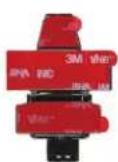
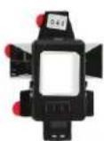
A) 2 Sensors
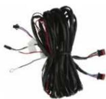
B) Wiring harness
C) Accessories
A
B
natural_image
Coiled black cable with red connectors and wires, no visible text or symbolsC
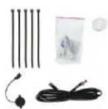
TABLE OF CONTENTS
Technical Tip....2
Installation 3-5
Calibration 6
Wiring digrams and specs 4-5
TOOLS REQUIRED
- Wire stripper
- Tape
• Digital Multi-meter - Cutter
- Alcohol wipes/cleaning pads
Attention! When testing the aftermarket equipment, ensure that all factory equipment is connected before cycling the key to ignition.
TECHNICAL TIP
Installation
NOTE: This installation may require the removing of the bumper to get the proper sensor alignment.
- Before removing of the bumper (if it is needed) iBEAM suggests measuring the placement of the sensors on the outside of the bumper with the provided ruler and painters tape.
- Tape off the vertical mounting location 15-24 inches from the ground. Find the latest surface possible. (Figure A.1)
- Find the center of the bumper. Tape off two positions between 10 and 20 inches from the center on the left and right hand side. Again, find the flatest surface possible. (Figure A.2)
- These tape markswill be used to indicate where on the opposite side the sensors will be mounted once the bumper is removed.
- Remove the bumper. Each vehicle is different. Take care with removal, lay a cloth on the ground to protect the exterior paint from damage.
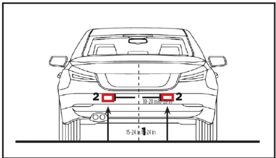
Figure A
INSTALLATION
Finding a reverse signal
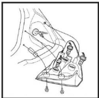
- Remove the tail light from the vehicle to allow access to the light bulbs wiring. (If help is needed, review the vehicles owners manual section on replacing the tail light bulbs.) (Figure A)
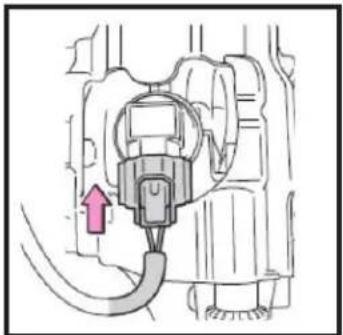
- Find the wiring that connects to the reverse bulb. There is normally 2 wires. (Figure B) Strip the insulation to expose the copper wire.
- Using a Digital Multi-meter on the DC Voltage setting, to verify the reverse wire. (Figure C)
-
Connect the wires from the TE-2SPK
-
Connect the RED wire to reverse, either found at the taillight or another source for reverse.
- Connect the BLACK wire to chassis ground.
natural_image
Technical line drawing of a mechanical assembly with no visible text or symbolsFigure A
natural_image
Diagram of a mechanical device with a red arrow indicating direction, no visible text or symbolsFigure B
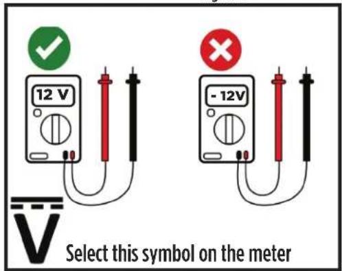
Figure C
INSTALLATION
Mounting of Sensors (Figure A)
NOTE: This installation may require the removing of the bumper to get the proper sensor alignment.
- Using the painters tape on the outside of the bumper as a guide, re-measure the desired sensor location on the inside of the bumper.
• 10-20 inches from the bumper center
• 15-24 inches from the ground
NOTE: Measurements do depend on the vehicles itself. There is a 4 inch tolerance on the measurements listed, but measurements can vary by vehicle. For example, a SUV may have a higher measurement from the ground.
- Clean the surface thoroughly where the sensors will be mounted on the inside of the bumper. Some dirt may cause the sensors to give false alerts.
- Remove the backing from the 3M double sided tape and use the provided adhesion promotor to assist in improving the adhesion to the bumper. Mount the sensors with the connector side mounting down towards the ground. Make sure the sensors are as straight as possible to each other and on the flatest surface possible on the bumper.
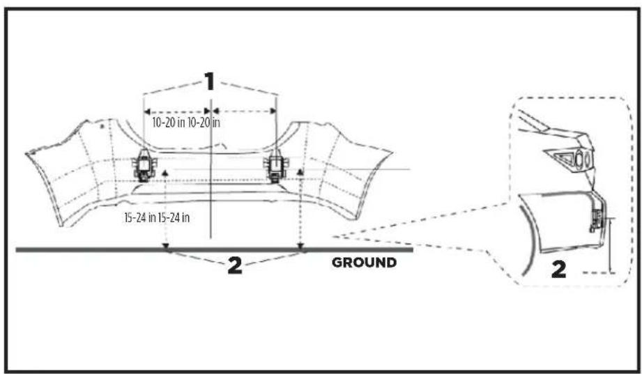
Figure A
INSTALLATION
Running the wiring
- Carefully find a safe location to run the wires along the bumper or underside of the bumper on the vehicle. Use zip ties to secure the wiring to the vehicle. Please keep away from moving parts and anything that would cause too much heat near the wiring. (Figure A)
- Find a suitable location to gain access to the inside of the vehicle.
- Mount the Audible buzzer inside the vehicle in a good loction that the driver will hear the alerts clearly. The wires may need to be extended is the location is desired near the front of the vehicle.
- Remove the double sided tape and mount to a flat surface. If needed the adhesion promotor can be used here also. (Figure B)
- |Plug the buzzer in. Please keep the connector next to the buzzer available. This is for the calibration button which is used in the next step. This button does NOT need to remain plugged in after calibration is finished.
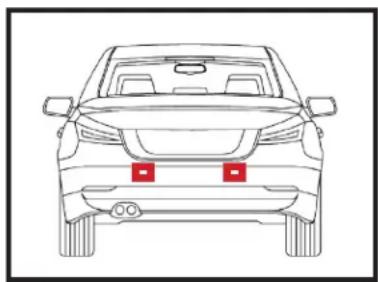
natural_image
Front view of a car with red license plate markings (no text or symbols)Figure A
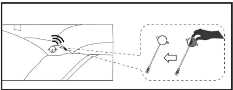
Figure B
CALIBRATION
Calibration
- Complete the installation, put the bumper back in place, make sure power and ground are connected and the buzzer is plugged in. Connect the provided push button to the harness near the buzzer connection.
- Check power up and make sure there are no moving object within 3 feet of the rear of the vehicle. (Figure A)
- Press and hold the calibration button for more than 3 seconds to activate the parking sensor system. You should hear two continuous beeps. If not please repeat step 3.
- Check function of the parking sensors.
- There should be 3 zones of alerts
• Level 1: 3.2 FT to 2 FT - slow beeping
• Level 2: 2 FT to 1 FT - faster beeping
• Level 3: less than 1 FT - constant beeping
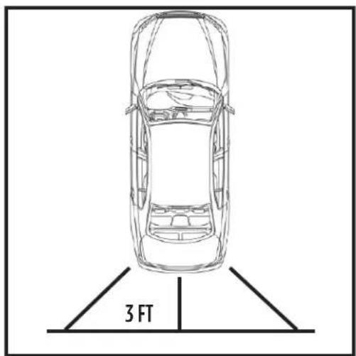
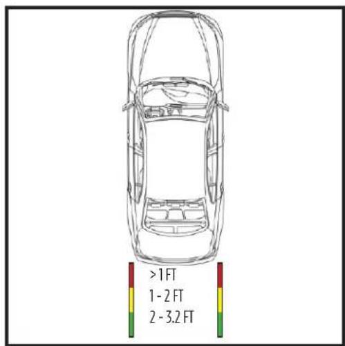
Figure AFigure A
WIRING DIAGRAM AND SPECS
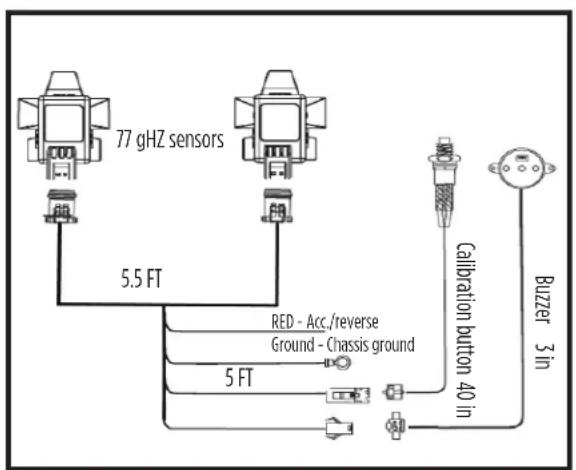
| Configuration Dual sensors | |
| Operating Freq. 77-81Ghz | |
| Active condition Speed < | 10km/h and reverse gear |
| Field of view (Horz) 144 degrees | |
| Alert range 3.2 FT max | |
| Weight per sensor 16g | |
| Dims per sensor 64.8 x 47.4 x 21.7 mm | |
| Operation/storage temp - | 40 to 85 C |
| Power consumption 200 | mA @ 12 VDC |
| Water resistant IP67 | |
| Voltage range 8 - 18V | |

BEAM
TE-2PSK
INSTALLATION INSTRUCTIONS
IBEAMSAFETY

Having difficulties? We're here to help.
Contact our Tech Support line at:
386-257-1187
Or via email at:
techsupport@metra-autosound.com
Tech Support Hours (Eastern Standard Time)
Monday - Friday: 9:00 AM - 7:00 PM
Saturday: 10:00 AM - 7:00 PM
Sunday: 10:00 AM - 4:00 PM

KNOWLEDGE IS POWER
Enhance your installation and fabrication skills to enrolling in the most recognized and respected
enrolling in the most recognized and resp mobile electronics school in our industry.
Log onto www.installerinstitute.com or call
800-354-6782 for more information and take steps toward a better tomorrow.

Metra Recommends MECP
certified technicians
Brand : Metra
Model : TE-2PSK
Category : Dash cam