
LED SAP-1024 - Lighting Controller Eurolite - Free user manual and instructions
Find the device manual for free LED SAP-1024 Eurolite in PDF.


| Product Type | Stand-alone DMX Player with PC Control Software |
| Dimensions (H x W x D) | 107 mm x 96 mm x 59 mm |
| Weight | 170 g |
| Power Supply | 9-36 V DC or 5 V via USB |
| Input Current | 200 mA |
| Power Consumption | 2 W |
| DMX Outputs | 2 x 512 (PC + Stand Alone) |
| DMX Speed | 1 to 45 Hz |
| Internal Memory | 4 MB (5000 steps with 512 channels, 100000 steps with 16 channels) |
| Standalone Mode | Yes, with internal RTC and calendar |
| External Triggers | 15 contact inputs (5 V) |
| IR Remote Support | Yes, via external IR module (optional) |
| RS232 Connection | Yes, with ASCII command protocol |
| Master/Slave Connection | Yes, up to 32 interfaces (3-wire, 20 m max cable) |
| Operating Temperature | -25°C to +70°C |
| IP Rating | IP20 |
| Certifications | CE, RoHS |
| System Compatibility | Windows XP/Vista/7/8/8.1/10, Mac OS X 10.6+, Linux |
| Place of Use | Indoor only |
| Maintenance | Clean with a dry, soft cloth. Do not use liquids or solvents. |
| Safety | Use only with specified power supply. Keep away from moisture and extreme temperatures. |
Frequently Asked Questions - LED SAP-1024 Eurolite
User questions about LED SAP-1024 Eurolite
0 question about this device. Answer the ones you know or ask your own.
Ask a new question about this device
Download the instructions for your Lighting Controller in PDF format for free! Find your manual LED SAP-1024 - Eurolite and take your electronic device back in hand. On this page are published all the documents necessary for the use of your device. LED SAP-1024 by Eurolite.
USER MANUAL LED SAP-1024 Eurolite
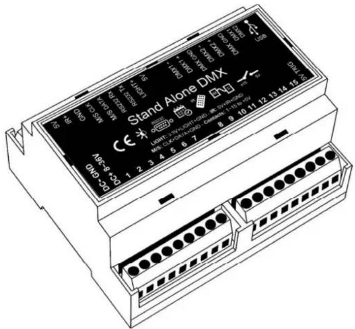
eurolite® LED SAP-1024
Stand-alone Player
User Manual
eurolite®
LED SAP-1024 HTS Standalone-Player
Stand-alone player incl. DMX control software PC-Control 1024
No. 51860159
www.eurolite.de
SUMMARY
Hardware Technical Specifications....3
Dimension of the interface....4
Front face....4
Top face....4
General pinout and device's connector....5
External triggers operation....5
USB (Yellow) LED Operation....6
DMX (RED) LED Operation....6
Interfaces Master/Slave connection....7
Setting of the Master/Slave interfaces....8
Infra-Red module connections (Optional)....9
IR REMOTE CONTROL unit and IR receiver (Optional)....10
DMX IN trigger connection....11
Dmx merging in standalone....12
Triggers configuration with the software....13
Switch to Standalone mode....13
External contact triggers 13
Infra-red remote triggers....14
RS232 Triggers....14
DMX IN triggers via another DMX signal in standalone....16
Time triggers with clock and calendar 17
Save and recover the last scene after the power cut off: 19
Scene trigger priorities: 19
HARDWARE TECHNICAL SPECIFICATIONS
Input/Output Connectors: Screw terminal (3*9 + 6 pins), Mini USB 2.0
External triggers: x15 contacts (5V.) (20m max cable length)
Type of Case : DIN, compatible Din rail
Master/Slave connection: Yes 3 wires for 32 connected interfaces max (20m max cable length)
Infra-Red connection: Yes via an external IR module and 3 connection wires (15m away max)
RS232 connection: Yes can receipt and send 16 characters max via the RS232 Protocol
Light Sensor: Yes 3 wires (15m away max)
Number of DMX Outputs: 2 x 512 (PC + Stand Alone)
DMX Speed: 1 to 45 Hz, MaB, Bk
Stand Alone Mode: Yes
Internal Clock (RTC): Yes
Internal calendar: Yes
Backups of the internal clock: Yes, 4 weeks without power (Internal rechargeable battery)
Internal memory: Yes (4 MB)
Memory Capacity: 5000 steps with 512 channels, 100 000 steps with 16 channels
Power Supply input: 9-36V or 5V with USB
Input Current: 200 mA
Power: 2 W
Contact Input Voltage (stand-alone) Contacts 3.3V\~5 V DC
DMX Isolation : Fuse and diode 3000V
Dimensions: H: 107 mm, W: 96 mm, D: 59 mm (pcb: 102/86/19)
Weight: 170g
Color: Beige
Operating temperatures: -25 to +70 °C
Certificates: CE, RoHS
IP Rating: IP20
Place of Use: Indoor
Storage: Keep in a dry place
Warranty: 36 months
Compatibility: 8 and 16 bit DMX fixtures
System Compatibility: Windows XP, Vista, 7, 8, 8.1, 10, MAC OS X (10.6 and higher), Linux
DIMENSION OF THE INTERFACE
The metric system is used. The unit is mm
FRONT FACE

other
| Dimension | Value | |---|---| | Top Section | 14 | | Top Section (Right) | 8 | | Top Section (Left) | 45 | | Bottom Section | 26 | | Bottom Section (Left) | 37 | | Bottom Section (Right) | 27 | | Middle Section | 9 | | Middle Section (Right) | 22 | | Middle Section (Left) | 27 | | Bottom Section (Right) | 58 | | Bottom Section (Left) | 90 | | Bottom Section (Right) | 27 | | Bottom Section (Left) | 90 |TOP FACE

GENERAL PINOUT AND DEVICE'S CONNECTOR
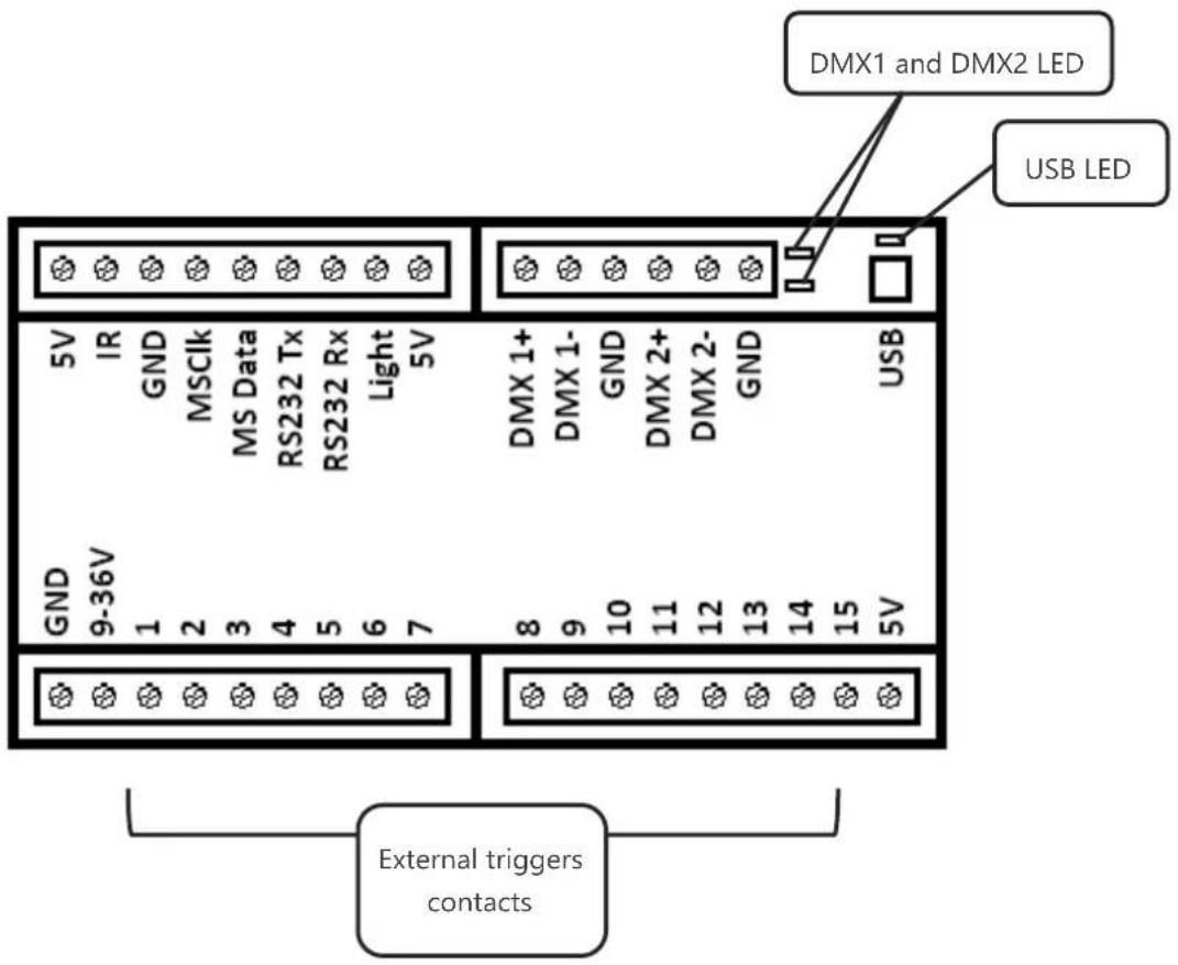
It is possible to use 15 externals contacts.
You have to connect contacts's Pin (here 1 and 2) to 5V to trigger a scene.

OFF: Interface is not powered (check the power) or have a problem.
Normal Blinking: USB communication with software is active.
Slow Blinking : Interface is in stand alone mode.
OFF: No DMX signal on the line.
ON: DMX signal is active and send on the DMX line.
Blinking: DMX signal speed is slower.
INTERFACES MASTER/SLAVE CONNECTION
Master/Slave mode allows to synchronize scenes and trigger actions of several interfaces together.
To use interfaces as Master/Slave, you have to connect the interfaces each others from the screw terminals. You need to connect together the pins M/S Data, M/S CLK and GND, as following:
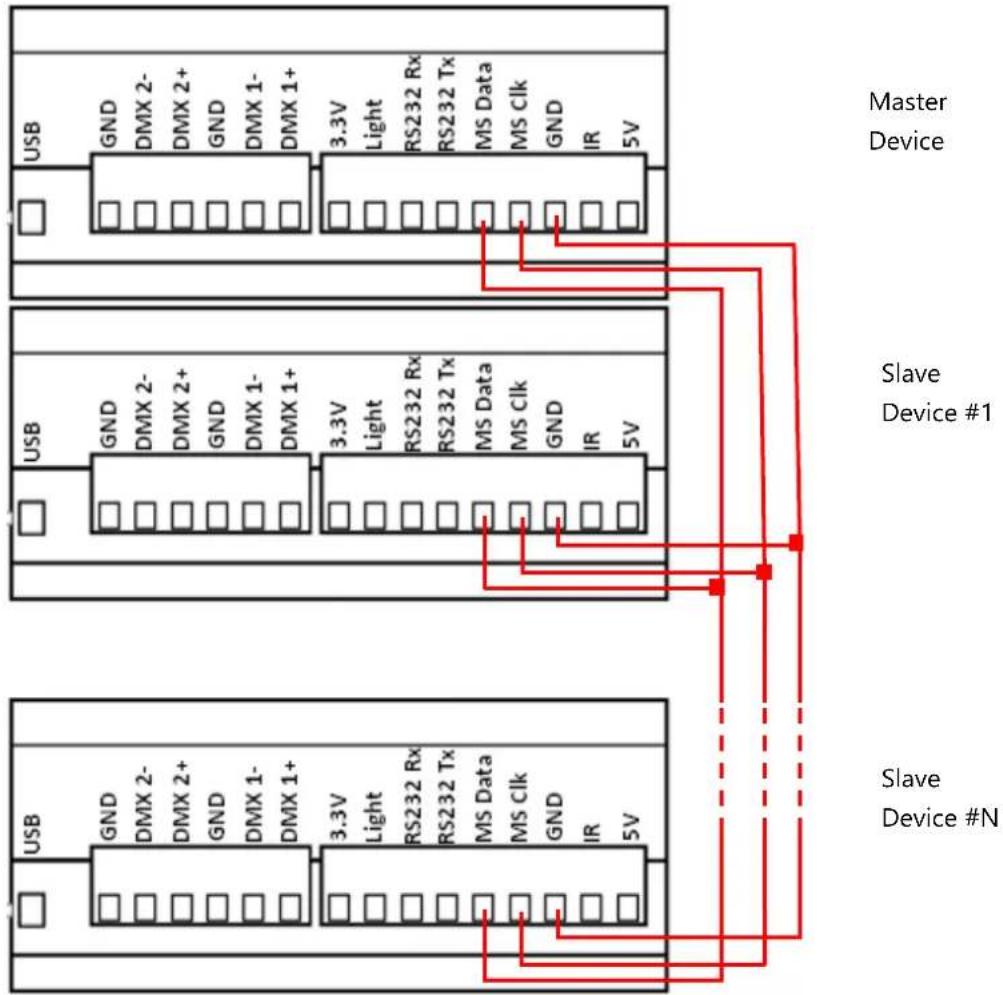
Interfaces configured as slave will strictly follow the clock, triggers and information providing by the master interface. Only one master interface at a time is possible.
SETTING OF THE MASTER/SLAVE INTERFACES
When multiple interfaces are connected with USB, the standalone mode allows to set them as Master/Slave. This mode allows to synchronize many interfaces and mutualize their standalone spaces combining the universes. (Up to 32 standalone universes)
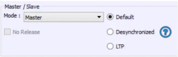
The Stand Alone mode allows to choose 1 interface and to define this interface as Master from the interface list, it is possible to choose only one to be the Master, all the other one will be configured as slave by default. The interfaces are always ordered by serial number ascending order.
A single interface can be defined as master (lower serial number by default), others ones are automatically set to slaves. The master device play the current scene and synchronize the slave ones. The master forces the slave interfaces to play the same scene and the same step at the same time. The slave interfaces are forced to follow the master timings and triggers and they cannot act, play or trigger a scene independently. Master can trigger on and trigger off scenes of the slave interfaces.
- MODE MASTER/SLAVE « Desynchronized »
An interface can be defined as master, others are automatically set to slaves. All Triggers On or Off operated on the master interface are effective to slave ones. However slave interfaces are not synchronized with master's timing and keep individual controls. Consequently slaves can trigger and play different scenes at any time and not synchronized with the master ones. The master acts like a general remote imposing triggering to the slaves with total priority. Master can trigger ON and trigger OFF scenes of the slave interface.
LTP means Latest Takes Priority. All interfaces are defined as slaves. Interfaces are not synchronized with timing and can trigger and play different scenes by itself. However triggers from an interface are passed to the others connected interfaces automatically and slave interfaces are forced to trigger the same scene. Here each interface acts like a general remote imposing triggering to the other slaves without synchronization.
• THE «NO RELEASE» Option
This option is only available with LTP or DESYNCHRONIZED modes. Only triggers ON from the master interface are executed and effective. All triggers OFF are ignored and slaves interfaces keep playing their current scene. Each Slave interface can choose to release or not its scene depend on the option is activated or not.
INFRA-RED MODULE CONNECTIONS (OPTIONAL)
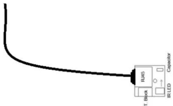
An external Infra-Red module is required. It connects as following: GND (pin 1 or 10) + 5V. DC out (pin 2) + IR Signal (pin 11).

IR REMOTE CONTROL UNIT AND IR RECEIVER (OPTIONAL)

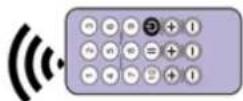
Button 1 to 10 must be assigned to a scene via the software.
Each button can trigger a different scene. With the remote control, a scene cannot be stop directly with the assigned button. To stop it you must press the Stop/Black Out button or trigger another scene.
Pause button to freeze the current scene to its actual state.
Stop/Black Out button to stop the current scene and play the empty scene number 00. All DMX channels are set down to 00 levels.
+/- for scene trigger. Select the next or previous scene automatically. You don't need to hold the button to validate and play a scene. The next or previous scene will play directly after selected.
+/- for Scene speed. Increase or decrease the speed of the current scene. A different speed can be chosen separately for each scene.

+/- for General dimmer. Increase or decrease the RGB, CMY and dimmer channels of the fixtures. The CMY, RGB, Dimmer channels are defined in the Profile of the fixture.
To use the IR remote control, an external PCB with an IR receiver LED must be connected before to the RJ45 #1 of the Stand Alone interface. The standard RJ45 cable distance is about 20 meters maximum.
IR PCB Pin assignment:
-With RJ45: use Pins #3=Ground; Pin #4 = IR Data ; Pin #7 = 5V DC -With T. Block: use Pins O = IR Data ; V = 5V DC ; G = Ground.
DMX IN TRIGGER CONNECTION

flowchart
graph TD
    A["Standard DMX Controller board"] -->|DMX-B Must be turned into Input in the software.| B["DMX B"]
    B --> C["DMX A"]
    C --> D["DMX Output, playing scenes triggered with de DMX Board via the DMX IN signal."]
    E["The DMX Output is connected to the interface input."] --> F["DMX B"]
DMX MERGING IN STANDALONE
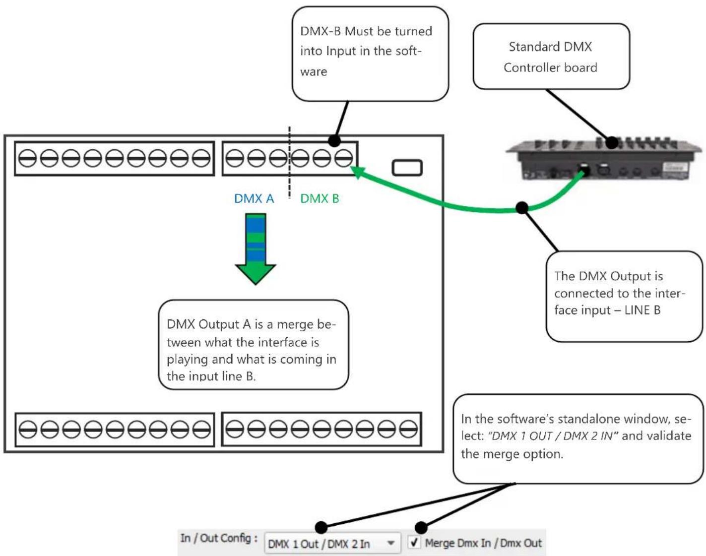
DMX Merging is available for the DIN interfaces because it takes two DMX lines to make a merge.
One DMX line must be turned into an input to capture the dmx signal provided by an external DMX board or by another DMX interface.
The interface will merge the input signal with its own output signal by comparing DMX levels with a HTP filter. Merging is a solution to keep manual control on channels, using a DMX Board for example. It's also a way to create a multi-zones system by merging several interfaces on one final DMX line.
flowchart
graph TD
    A["DMX-A"] -->|DMX B| B["DMX-B Must be turned into Input in the software"]
    B --> C["Standard DMX Controller board"]
    C --> D["The DMX Output is connected to the interface input – LINE B"]
    D --> E["In the software's standalone window, select: "DMX 1 OUT / DMX 2 IN" and validate the merge option."]
    E --> F["Merge Dmx In / Dmx Out"]
    F --> G["DMX Output A is a merge between what the interface is playing and what is coming in the input line B."]
    G --> H["In / Out Config: DMX 1 Out / DMX 2 In"]
TRIGGERS CONFIGURATION WITH THE SOFTWARE
The Stand Alone mode of the software enables to configure and personalize all the triggers.
The information will be directly saved in the DMX interface memory with the memory writing function.
SWITCH TO STANDALONE MODE
When the device isn't connected to the software or has just been powered, it enters in Stand Alone mode after five (5) seconds.
EXTERNAL CONTACT TRIGGERS
The Stand Alone mode offers up to 15 external triggers.
By selecting a scene in the list, it's possible to choose the external contact number (from 01 to 15) to trigger the scene.

Several trigger options are available for externals contacts triggers:
On : Activate the contact only allow you to play the scene.
On/Off : Activate the contact allow you to play and stop a scene. Each trigger action will invert the state of the scene (start/stop).
Auto Release: The scene plays while the contact is activated. Keep the contact activated to play the scene, when the contact is released the scene stop.
Restart : Activate the contact restart the scene from its beginning, if the scene is of, then it start to play. Activate the contact will restart the scene from its beginning automatically. If the scene is off already, then it will play.
INFRA-RED REMOTE TRIGGERS
Standalone mode offers up to 10 triggers with the Infrared remote. By selecting a scene in the list, it's possible to choose the remote button number (from 01 to 10) to trigger the scene. The other IR remote functions will work as well as the SLIM DMX interface. (Speed, dimmer, scene +, scene -, off).

RS232 TRIGGERS
Standalone mode allows to use the RS232 protocol to control the DMX interface with the commands describe in the help topic
![RS232 Protocol -- Specifications -- Asynchronous, 9600 bps, No Parity, 8 Data Bit, 2 Stop Bit -- General -- Start of Text : 02h (STX) End of Text : 03h (ETX) ZONEX : Set the current Zone (X = a, b, c, d, e, f) SCXXX : Start / Stop the scene XXX of the current zone (XXX = 001-255 / SC000 = Black out) STOP0 : Black Out -- Commands for the current scene -- PLAY0 : Play PAUSE : Pause DIM++ : Dimmer + DIM-- : Dimmer - DIM+X : Set positive dimmer value (X = 0-9 / 0 = default dimmer value) DIM-X : Set negative dimmer value (X = 0-9 / 0 = default dimmer value) SPD++ : Speed + SPD-- : Speed - SPD+X : Set positive speed value (X = 0-9 / 0 = default speed value) SPD-X : Set negative speed value (X = 0-9 / 0 = default speed value) -- Colors -- COLRX : Trigger button X of the color mode (X = 1-8) CLRXX : Trigger color X of the predefined colors (X = 00-99) CLR00 : Turn off color -- Example (Start scene 2) -- [STX]SC002[ETX] OK](/content/2026/05/832315/images/87194c46b5d5041405cf2a9e9e4a56ed7054a50069aae2c1ad572f77af2bdd39.jpg)
Connect the RS232 transmitter to the interface RS232 and GND pins and send the dedicated ASCII commands lines that you need.
The ASCII commands need to be send one time only to be processed by the interface.

ASCII TABLE
| Decimal | Hexadecimal | Binary | Octal | Char | Decimal | Hexadecimal | Binary | Octal | Char | Decimal | Hexadecimal | Binary | Octal | Char |
| 0 | 0 | 0 | 0 | [NULL] | 48 | 30 | 110000 | 60 | 0 | 96 | 60 | 1100000 | 140 | |
| 1 | 1 | 1 | 1 | [START OF HEADING] | 49 | 31 | 110001 | 61 | 1 | 97 | 61 | 1100001 | 141 | a |
| 2 | 2 | 10 | 2 | [START OF TEXT] | 50 | 32 | 110010 | 62 | 2 | 98 | 62 | 1100010 | 142 | b |
| 3 | 3 | 11 | 3 | [END OF TEXT] | 51 | 33 | 110011 | 63 | 3 | 99 | 63 | 1100011 | 143 | c |
| 4 | 4 | 100 | 4 | [END OF TRANSMISSION] | 52 | 34 | 110100 | 64 | 4 | 100 | 64 | 1100100 | 144 | d |
| 5 | 5 | 101 | 5 | [ENQUIRY] | 53 | 35 | 110101 | 65 | 5 | 101 | 65 | 1100101 | 145 | e |
| 6 | 6 | 110 | 6 | [ACKNOWLEDGE] | 54 | 36 | 110110 | 66 | 6 | 102 | 66 | 1100110 | 146 | f |
| 7 | 7 | 111 | 7 | [BELL] | 55 | 37 | 110111 | 67 | 7 | 103 | 67 | 1100111 | 147 | g |
| 8 | 8 | 1000 | 10 | [BACKSPACE] | 56 | 38 | 111000 | 70 | 8 | 104 | 68 | 1101000 | 150 | h |
| 9 | 9 | 1001 | 11 | [HORIZONTAL TAB] | 57 | 39 | 111001 | 71 | 9 | 105 | 69 | 1101001 | 151 | i |
| 10 | A | 1010 | 12 | [LINE FEED] | 58 | 3A | 111010 | 72 | : | 106 | 6A | 1101010 | 152 | j |
| 11 | B | 1011 | 13 | [VERTICAL TAB] | 59 | 3B | 111011 | 73 | ; | 107 | 6B | 1101011 | 153 | k |
| 12 | C | 1100 | 14 | [FORM FEED] | 60 | 3C | 111100 | 74 | < | 108 | 6C | 1101100 | 154 | l |
| 13 | D | 1101 | 15 | [CARRIAGE RETURN] | 61 | 3D | 111101 | 75 | = | 109 | 6D | 1101101 | 155 | m |
| 14 | E | 1110 | 16 | [SHIFT OUT] | 62 | 3E | 111110 | 76 | > | 110 | 6E | 1101110 | 156 | n |
| 15 | F | 1111 | 17 | [SHIFT IN] | 63 | 3F | 111111 | 77 | ? | 111 | 6F | 1101111 | 157 | o |
| 16 | 10 | 10000 | 20 | [DATA LINK ESCAPE] | 64 | 40 | 1000000 | 100 | @ | 112 | 70 | 1110000 | 160 | p |
| 17 | 11 | 10001 | 21 | [DEVICE CONTROL 1] | 65 | 41 | 1000001 | 101 | A | 113 | 71 | 1110001 | 161 | q |
| 18 | 12 | 10010 | 22 | [DEVICE CONTROL 2] | 66 | 42 | 1000010 | 102 | B | 114 | 72 | 1110010 | 162 | r |
| 19 | 13 | 10011 | 23 | [DEVICE CONTROL 3] | 67 | 43 | 1000011 | 103 | C | 115 | 73 | 1110011 | 163 | s |
| 20 | 14 | 10100 | 24 | [DEVICE CONTROL 4] | 68 | 44 | 1000100 | 104 | D | 116 | 74 | 1110100 | 164 | t |
| 21 | 15 | 10101 | 25 | [NEGATIVE ACKNOWLEDGE] | 69 | 45 | 1000101 | 105 | E | 117 | 75 | 1110101 | 165 | u |
| 22 | 16 | 10110 | 26 | [SYNCHRONOUS IDLE] | 70 | 46 | 1000110 | 106 | F | 118 | 76 | 1110110 | 166 | v |
| 23 | 17 | 10111 | 27 | [ENG OF TRANS. BLOCK] | 71 | 47 | 1000111 | 107 | G | 119 | 77 | 1110111 | 167 | w |
| 24 | 18 | 11000 | 30 | [CANCEL] | 72 | 48 | 1001000 | 110 | H | 120 | 78 | 1111000 | 170 | x |
| 25 | 19 | 11001 | 31 | [END OF MEDIUM] | 73 | 49 | 1001001 | 111 | I | 121 | 79 | 1111001 | 171 | y |
| 26 | 1A | 11010 | 32 | [SUBSTITUTE] | 74 | 4A | 1001010 | 112 | J | 122 | 7A | 1111010 | 172 | z |
| 27 | 1B | 11011 | 33 | [ESCAPE] | 75 | 4B | 1001011 | 113 | K | 123 | 7B | 1111011 | 173 | { |
| 28 | 1C | 11100 | 34 | [FILE SEPARATOR] | 76 | 4C | 1001100 | 114 | L | 124 | 7C | 1111100 | 174 | | |
| 29 | 1D | 11101 | 35 | [GROUP SEPARATOR] | 77 | 4D | 1001101 | 115 | M | 125 | 7D | 1111101 | 175 | } |
| 30 | 1E | 11110 | 36 | [RECORD SEPARATOR] | 78 | 4E | 1001110 | 116 | N | 126 | 7E | 1111110 | 176 | ~ |
| 31 | 1F | 11111 | 37 | [UNIT SEPARATOR] | 79 | 4F | 1001111 | 117 | O | 127 | 7F | 1111111 | 177 | [DEL] |
| 32 | 20 | 100000 | 40 | [SPACE] | 80 | 50 | 1010000 | 120 | P | |||||
| 33 | 21 | 100001 | 41 | ! | 81 | 51 | 1010001 | 121 | Q | |||||
| 34 | 22 | 100010 | 42 | " | 82 | 52 | 1010010 | 122 | R | |||||
| 35 | 23 | 100011 | 43 | # | 83 | 53 | 1010011 | 123 | S | |||||
| 36 | 24 | 100100 | 44 | $ | 84 | 54 | 1010100 | 124 | T | |||||
| 37 | 25 | 100101 | 45 | % | 85 | 55 | 1010101 | 125 | U | |||||
| 38 | 26 | 100110 | 46 | & | 86 | 56 | 1010110 | 126 | V | |||||
| 39 | 27 | 100111 | 47 | 87 | 57 | 1010111 | 127 | W | ||||||
| 40 | 28 | 101000 | 50 | ( | 88 | 58 | 1011000 | 130 | X | |||||
| 41 | 29 | 101001 | 51 | 89 | 59 | 1011001 | 131 | Y | ||||||
| 42 | 2A | 101010 | 52 | * | 90 | 5A | 1011010 | 132 | Z | |||||
| 43 | 2B | 101011 | 53 | + | 91 | 5B | 1011011 | 133 | [ | |||||
| 44 | 2C | 101100 | 54 | 92 | 5C | 1011100 | 134 | |||||||
| 45 | 2D | 101101 | 55 | 93 | 5D | 1011101 | 135 | |||||||
| 46 | 2E | 101110 | 56 | 94 | 5E | 1011110 | 136 | |||||||
| 47 | 2F | 101111 | 57 | 95 | 5F | 1011111 | 137 |
DMX IN TRIGGERS VIA ANOTHER DMX SIGNAL IN STANDALONE
The Stand Alone mode offers up to 512 DMX IN channel triggers and up to 255 DMX trigger values per channel. By selecting a scene in the list, it's possible to choose the channel number and the DMX value to trigger the scene. The scene will play when the value of the DMX channel is reached or exceeded.

One DMX Output must be turned into an input in the Options windows. To access this window click on the software menu: Tools > Options then click to select the device section as following:

flowchart
graph TD
    A["Device Section"] --> B["General"]
    B --> C["Device"]
    C --> D["Audio / Midi"]
    D --> E["Define input"]
    E --> F["ART NET"]
TIME TRIGGERS WITH CLOCK AND CALENDAR
The Stand Alone mode has an internal clock and a calendar. It's possible to assign a time trigger on every scene of the list. By selecting a scene on the list, it's possible to choose the start and end dates and hours and days of the week. You can thus create a lot of scenarios.
CASE 1: Programming a unique trigger:
- Start schedule:

The scene is triggered a single time at the given date and time.
• End schedule:
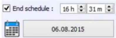
The scene is stopped at the given date and time.
CASE 2: Programming a repeating trigger:
- Start schedule:

Date from which-one the scene will be playable according to the programmed triggers
- End schedule:

Date after witch-one triggers will be ignored. With no End date, triggers are permanent
• List of the months of the year

The 12 check boxes represents the 12 months of the year (J) January to (D) December. The triggers will be performed on the activated months. Next, a daily hours range must be defined.
- Start and Stop days

With a monthly repetition, you can choose the starting and stopping days for each chosen month. In this example triggers can happen between the 1^st and the 15^th of each chosen month.
• List of the days of the week

The 7 check boxes represents the 7 days in a week. The triggers will be performed on the activated days only. Next, a time range must be defined.

- Start time
The starting time is the time when the scene will be triggered for each chosen day. Of course chosen months, start and end schedule days are included.
- Release time

The release time is the time when the scene will stop for each chosen day. Of course chosen months, start and end schedule days are included. The release time is not mandatory, if it's not defined, the scene will keep playing until another trigger event happens. (Like the triggering of another scene for example).
NOTE: For a daily repetition, if the starting time is later than the release time then the triggering will stopped the next day, even if the next day has not been selected.
SAVE AND RECOVER THE LAST SCENE AFTER THE POWER CUT OFF:
Scenes with a start schedule and a stop schedule are set on a defined time space and can be memorized. The interface save the last scene played before the power cut off and recover it when the power is restored. The scene must obligatory include a start schedule and a stop schedule activate this option.
SCENE TRIGGER PRIORITIES:
When several scenes have the same time trigger (date + hour + minute), only the first scene in thelist will be triggered. The rest will be ignored
- eurolite® LED SAP-1024
- SUMMARY
- Hardware Technical Specifications....3
- Dimension of the interface....4
- General pinout and device's connector....5
- Interfaces Master/Slave connection....7
- Infra-Red module connections (Optional)....9
- IR REMOTE CONTROL unit and IR receiver (Optional)....10
- DMX IN trigger connection....11
- Dmx merging in standalone....12
- Triggers configuration with the software....13
- HARDWARE TECHNICAL SPECIFICATIONS
- DIMENSION OF THE INTERFACE
- GENERAL PINOUT AND DEVICE'S CONNECTOR
- INTERFACES MASTER/SLAVE CONNECTION
- SETTING OF THE MASTER/SLAVE INTERFACES
- - MODE MASTER/SLAVE « Desynchronized »
- • THE «NO RELEASE» Option
- INFRA-RED MODULE CONNECTIONS (OPTIONAL)
- IR REMOTE CONTROL UNIT AND IR RECEIVER (OPTIONAL)
- IR PCB Pin assignment:
- DMX IN TRIGGER CONNECTION
- DMX MERGING IN STANDALONE
- TRIGGERS CONFIGURATION WITH THE SOFTWARE
- SWITCH TO STANDALONE MODE
- EXTERNAL CONTACT TRIGGERS
- INFRA-RED REMOTE TRIGGERS
- RS232 TRIGGERS
- DMX IN TRIGGERS VIA ANOTHER DMX SIGNAL IN STANDALONE
- TIME TRIGGERS WITH CLOCK AND CALENDAR
- CASE 1: Programming a unique trigger:
- - Start schedule:
- • End schedule:
- CASE 2: Programming a repeating trigger:
- - End schedule:
Brand : Eurolite
Model : LED SAP-1024
Category : Lighting Controller