
A41 - Measurement ABB - Free user manual and instructions
Find the device manual for free A41 ABB in PDF.


| Product Type | Energy Meter |
| Brand | ABB |
| Model | A41 |
| Category | Measurement |
| Dimensions | Approximately 72 x 100 x 65 mm (DIN rail mount) |
| Weight | 0.23 kg |
| Power Supply | 230 V AC nominal, range 57.7–288 V AC, 50/60 Hz |
| Display | 96x64 pixel LCD, 39x26 mm view area |
| Measurement Functions | Active, reactive, apparent energy; import/export; harmonics up to 16th; demand; load profile |
| Accuracy | Class 1 (active energy) per IEC 62053-21 |
| Communication Interfaces | RS-485 (Modbus, EQ-Bus), M-Bus, IR (M-Bus/EQ-Bus), pulse outputs |
| Inputs/Outputs | Up to 4 configurable digital I/Os (pulse, alarm, tariff, etc.) |
| Operating Temperature | -40°C to +70°C |
| Storage Temperature | -40°C to +85°C |
| Humidity | 75% yearly average, 95% on 30 days/year |
| Protection Class | IP20 (terminal block), IP51 in enclosure |
| Mounting | DIN rail (DIN 50022), wall or flush mount with accessories |
| Safety | Install by qualified personnel; use fuses on incoming side; IEC 62052-31 UC2 |
| Maintenance | Refer to manual for service; no user-serviceable parts inside |
Frequently Asked Questions - A41 ABB
User questions about A41 ABB
0 question about this device. Answer the ones you know or ask your own.
Ask a new question about this device
Download the instructions for your Measurement in PDF format for free! Find your manual A41 - ABB and take your electronic device back in hand. On this page are published all the documents necessary for the use of your device. A41 by ABB.
USER MANUAL A41 ABB
| Disclaimer | The information in this document is subject to change without notice and should not be construed as a commitment by ABB Spa. ABB Spa assumes no responsi-bility for any errors that may appear in this document.In no event shall ABB Spa be liable for direct, indirect, special, incidental or con-sequential damages of any nature or kind arising from the use of this document, nor shall ABB Spa be liable for incidental or consequential damages arising from use of any software or hardware described in this document. |
| Copyrights | This document and parts thereof must not be reproduced or copied without written permission from ABB Spa, and the contents thereof must not be imparted to a third party nor used for any unauthorized purpose.The software or hardware described in this document is furnished under a license and may be used, copied, or disclosed only in accordance with the terms of such license.© Copyright 2020 ABB Spa. All rights reserved. |
| Trademarks | ABB Spa is a registered trademark of the ABB Group. All other brand or product names mentioned in this document may be trademarks or registered trademarks of their respective holders. |
| Contact | ABB Spavia dell'Industria, 1820009 - Vittuone - MilanoItalyTel: +39 02 2415 0000 |
Table of Content
1 Product Overview ...... 9
1.1 Meter Parts 10
1.2 Meter Types 12
2 Installation 15
2.1 Mounting the Meter 16
2.2 Environmental Considerations 18
2.3 Installing the Meter 19
2.3.1 Configuring the meter 20
2.4 Wiring Diagrams 21
2.4.1 Direct connected meters 21
2.4.2 Transformer connected meters without voltage transformer 21
2.4.3 Transformer connected meters with voltage transformer 22
2.4.4 Inputs/outputs 22
2.4.5 Communication 23
3 User Interface 25
3.1 Display 26
4 Meter Settings 31
4.1 Settings and Configurations 32
4.1.1 Setting Date 32
4.1.2 Setting Time 33
4.1.3 Setting Ratios 33
4.1.4 Setting Pulse Output 33
4.1.5 Setting I/O 34
4.1.6 Setting Alarm 35
4.1.7 Setting Currency/CO2 36
4.1.8 Setting M-Bus 36
4.1.9 Setting RS-485 37
4.1.10 Setting IR Side 37
4.1.11 Setting Upgrade Consent 39
4.1.12 Setting Pulse LED 39
4.1.13 Setting Tariff 39
4.1.14 Setting Previous Values 40
4.1.15 Setting Load Profile 40
4.1.16 Setting Demand 41
4.1.17 Resetting Resettable Registers 41
5 Technical Description 43
5.1 Energy Values 44
5.2 Instrumentation 46
5.3 Harmonics 47
5.3.1 Measuring Harmonics 49
5.4 Alarm 51
5.5 Inputs and Outputs 52
5.5.1 Tariff Inputs 52
5.5.2 Pulse Outputs 53
5.5.2.1 Pulse Frequency and Pulse length 53
5.6 Internal Clock 55
5.6 Internal Clock 55
5.7 Logs 56
5.7.1 System Log 56
5.7.2 Event Log 57
5.7.3 Net Quality Log 57
5.7.4 Audit Log 58
5.7.5 Settings Log 58
5.7.6 Event codes 58
5.8 Demand 60
5.9 Previous Values 62
5.10 Load Profile 64
6 Technical data 67
6.1 Technical Specifications 68
6.2 Physical dimensions 72
7 Measurement Methods ...... 73
7.1 Measuring Energy 74
7.1.1 Single Phase, 1-Element Metering 76
8 Service & Maintenance 79
8.1 Service and Maintenance 80
9 Communication with Modbus 81
9.1 Bus Description 82
9.2 About the Modbus Protocol 83
9.2.1 Function Code 3 (Read holding registers 83
9.2.2 Function Code 16 (Write multiple registers) 85
9.2.3 Function Code 6 (Write single register) 86
9.2.3.1 Exception Responses 87
9.3 Reading and Writing to Registers 88
9.5 Historical Data 100
9.5.1 Quantity identifiers 103
9.6 Previous Values 108
9.6.1 Reading Previous Values 110
9.7 Demand 112
9.7.1 Reading Demand 114
9.8 Event logs 116
9.8.1 Reading Event logs 118
9.9 Load profile 119
9.9.1 Reading Load profile 121
9.10 Configuration 122
9.10.1 Previous values 122
9.10.2 Demand 123
9.10.3 Load profile 126
9.10.4 Alarms 127
9.10.5 Inputs and outputs 131
9.10.6 Tariffs 133
9.10.7 Daylight Savings Time 140
10 Communication with M-Bus 143
10.1 Bus Description 145
10.2 Protocol Description 146
10.2.1 Telegram Format 151
10.2.1.1 Field description 151
10.2.2 Value Information Field codes 157
10.2.2.1 Standard VIF codes 157
10.2.2.2 Standard codes for VIFE used with extension indicator FDh 157
10.2.2.3 Standard codes for VIFE 158
10.2.2.4 First manufacturer specific VIFE-codes 158
10.2.2.5 VIFE-Codes for reports of record errors (meter to master) 160
10.2.2.6 VIFE-Codes for object actions (master to meter) 160
10.2.2.7 2:nd manufacturer specific VIFE followed after VIFE 1111 1000 (F8 hex): 160
10.2.2.8 2:nd manufacturer specific VIFE followed after VIFE 1111 1001 (F9 hex): 160
10.2.2.9 2:nd manufacturer specific VIFE followed after VIFE 1111 1110 (FE hex): 161
10.2.3 Communication process 161
10.2.3.1 Selection and secondary addressing 163
10.3 Standard Readout of Meter Data 164
10.3.1 Example of the 1st telegram (all values are hexadecimal) ..... 164
10.3.2 Example of 2nd telegram (all values are hexadecimal) 168
10.3.3 Example of 3rd telegram (all values are hexadecimal) ..... 172
10.3.4 Example of the 4th telegram (all values are hexadecimal) ..... 177
10.3.5 Example of the 5th telegram (all values are hexadecimal) ..... 181
10.3.6 Example of the 6th telegram (all values are hexadecimal) ..... 183
10.3.7 Example of the 7th telegram (all values are hexadecimal) ..... 187
10.3.8 Example of the 8th telegram (all values are hexadecimal 190
10.3.9 Example of the 9th telegram (all values are hexadecimal 193
10.4 Special Readout of Meter Data 196
10.4.1 Readout of Load Profile Data 197
10.4.1.1 Examples of Readouts of Load Profile Data 202
10.4.2 Readout of Demand Data 205
10.4.2.1 Examples of Readouts of Demand Data 206
10.4.3 Readout of Previous Values 211
10.4.3.1 Examples of Readouts of Previous Values 213
10.4.4 Readout of Event Log Data 216
10.4.4.1 Example of readout of log data 218
10.4.5 Readout of Current Harmonics 221
10.4.5.1 Examples of Readouts of Current Harmonics Data 222
10.4.6 Readout of Voltage Harmonics 230
10.4.6.1 Examples of readout of voltage harmonics data 231
10.5 Sending Data to the Meter 239
10.5.1 Set tariff 239
10.5.2 Set primary address 240
10.5.3 Change baud rate 240
10.5.4 Reset power fail counter 241
10.5.5 Set Current transformer (CT) ratio - primary current 241
10.5.6 Set voltage transformer (VT) ratio - primary voltage 242
10.5.7 Set current transformer (CT) ratio - secondary current 242
10.5.8 Set voltage transformer (VT) ratio - secondary voltage 243
10.5.9 Select status information 243
10.5.10 Reset of stored state for input 1 244
10.5.11 Reset of stored state for input 2 244
10.5.12 Reset of stored state for input 3 245
10.5.13 Reset of stored state for input 4 245
10.5.14 Reset of input counter 1 246
10.5.15 Reset of input counter 2 246
10.5.16 Reset of input counter 3 247
10.5.17 Reset of input counter 4 247
10.5.18 Set output 1 248
10.5.19 Set output 2 248
10.5.20 Set output 3 249
10.5.21 Set output 4 249
10.5.22 Reset power outage time 250
10.5.23 Send password 250
10.5.24 Set password 250
10.5.25 Set date and time 251
10.5.26 Set date 252
10.5.27 Reset demand, previous values, load profile and logs 252
10.5.28 Reset resettable active energy import 253
10.5.29 Reset resettable active energy export 253
10.5.30 Reset resettable reactive energy import 254
10.5.31 Reset resettable reactive energy export 254
10.5.32 Freeze demand 255
10.5.33 Set write access level 255
10.5.34 Set tariff source 256
10.5.35 Set CO2 conversion factor 256
10.5.36 Set currency conversion factor 257
11 Troubleshooting 259
11.1 Error, warnings and information codes 260
Chapter 1: Product Overview
Overview
This chapter describes the parts of the meter and the different meter types.
In this chapter
The following topics are covered in this chapter:
1.1 Meter Parts ...... 10
1.2 Meter Types 12
1.1 Meter Parts
Illustration
The parts of the meter are shown in the illustration below:
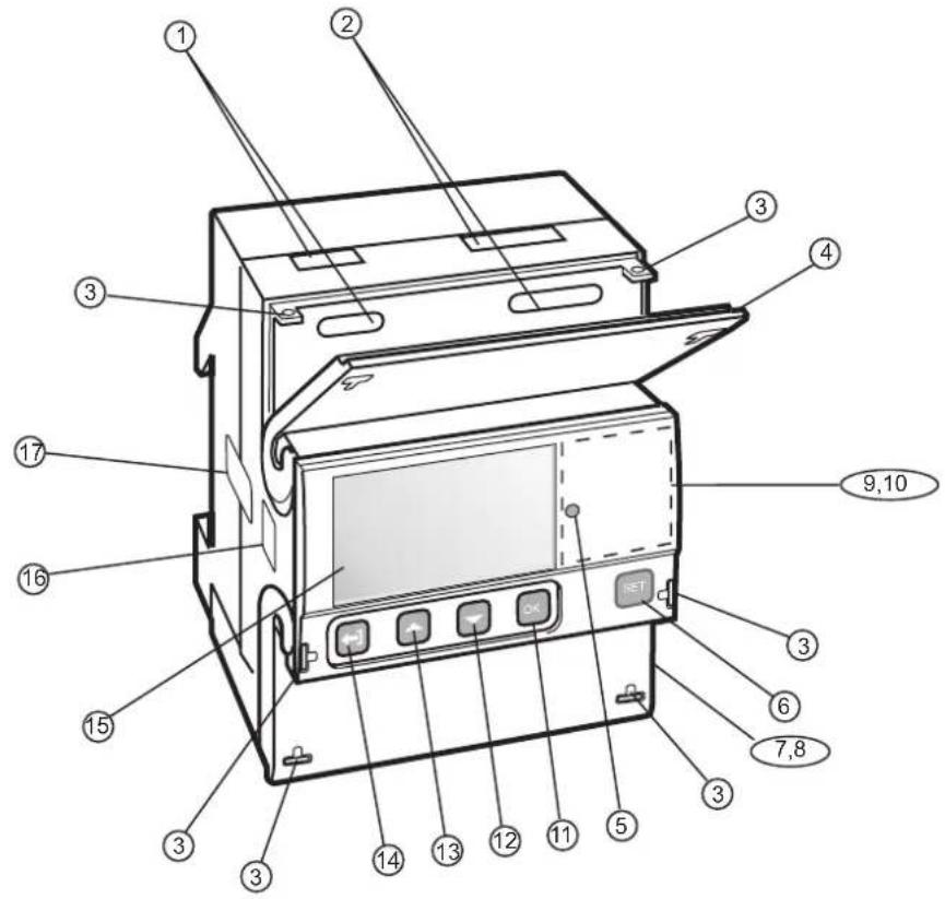
Parts description
The following table describes the parts of the meter:
| Item Description Comments | |
| 1 Terminal for communication connection | |
| 2 Terminal for input/output connection | |
| 3 Sealing point. Seal thread can be used to seal | the cover. |
| 4 Sealable terminal cover Protective cover with | printed wiring diagram on the inside. |
| 5 LED Flashes in proportion to the energy | measured. |
| 6 Set button Enter configuration mode | |
| 7 Sealable terminal cover Protective cover with | printed wiring diagram on the inside |
| 8 Terminal block Terminal for all voltages and cur-rents | currents |
| 9 Sealable cover To protect the LCD and seal the | set button |

| Item Description Comments | |
| 10 Product data Contains data about the meter type | |
| 11 OK button Perform an action or choose a menu | |
| 12 Down button Toggle down (toggle right in the main menu) | |
| 13 Up button Toggle up (toggle left in the main menu) | |
| 14 Exit button Exit to the previous menu or toggle between default and main menu. | |
| 15 Display LCD for meter reading | |
| 16 Optical communication interface For IR communication | |
| 17 Sealing | |
1.2 Meter Types
Main groups
The A41/A42 meters are divided into two main groups:
- Direct connected meters for currents ≤ 80A .
- Transformer connected meters for currents >80A using external current transformer with secondary current ≤ 6A and optional voltage transformer.
Subgroups
The main meter groups are further divided into subgroups depending on the functionality of the respective meter:
| Subgroup Functionality | |
| Platinum Active energy, Reactive energy, Apparent energy, Import/export of energy, Resettable energy registers, Harmonics, Configurable I/O (except the 690V meter which has fixed I/O), Advanced clock functions (load profiles), Basic clock functions (Tariff control, Previous values, Max/min demand, Event log), Class 0.5 or Class 1, Tariffs, Fixed I/O, Pulse output/alarm | |
| Gold Active energy, Reactive energy, Apparent energy, Import/export of energy, Resettable energy registers, Basic clock functions (Tariff control, Previous values, Max/min. demand, Event log), Class 0.5 or Class 1, Tariffs, Fixed I/O, Pulse output/alarm | |
| Silver Active energy, Reactive energy, Apparent energy, Import/export of energy, Resettable energy registers, Class 0.5 or Class 1, Tariffs, Fixed I/O, Active energy, Pulse output/alarm | |
| Bronze Active energy, Reactive energy, Apparent energy, Import/export of energy, Class 1, Pulse output/alarm | |
| Steel Active energy import, Class 1, Pulse output/alarm |
Product label
The meter type information that is reflected on the labels on the meter is shown in the picture below:

Product label information
The information on the product label is explained in the table below:
| Item Description | |
| 1 Import/export of energy | |
| 2 3-element metering | |
| 3 2-element metering | |
| 4 1-element metering | |
| 5 | LED |
| 6 Pulse output | |
| 7 Protection class II | |
| 8 Declaration of product safety | |
| 9 Type designation | |
| 10 Serial number | |
| 11 Accuracy active energy | |
| 12 Accuracy reactive energy | |
| 13 Voltage | |
| 14 Current | |
| 15 Frequency | |
| 16 LED pulse frequency | |
| 17 Pulse frequency | |
| 18 Temperature range | |
| 19 Date of manufacture (year and week) | |
| 20 ABB ID | |
| 21 Notified body | |
| 22 MID and year of verification | |
| 23 Caution, refer to accompanying document | |
Chapter 2: Installation
Overview
This chapter describes how to mount the A41/A42 meters and how to connect them to an electricity network. The chapter also contains information about how to perform a basic configuration of the meter.
Information about how to connect I/O and communication options is also included in this chapter.
In this chapter
The following topics are covered in this chapter:
2.1 Mounting the Meter 16
2.2 Environmental Considerations .... 18
2.3 Installing the Meter 19
2.3.1 Configuring the meter 20
2.4 Wiring Diagrams 21
2.4.1 Direct connected meters 21
2.4.2 Transformer connected meters without voltage transformer ..... 21
2.4.3 Transformer connected meters with voltage transformer ..... 22
2.4.4 Inputs/outputs 22
2.4.5 Communication 23
2.1 Mounting the Meter
| General | This section describes different ways to mount the A41/A42 meters. For some methods of mounting additional accessories are needed. For further information about accessories, refer to the Main Catalog (2CMC480001C0201). |
| DIN-rail mounted | The A41/A42 meters are intended to be mounted on a DIN-rail (DIN 50022). If this method of mounting is used no extra accessories are needed and the meter is fastened by snapping the DIN-rail lock onto the rail. |
| DIN-rail | The following picture shows a DIN-rail. |
| Wall mounted | The recommended way to mount the meter on a wall is to mount a separate DIN-rail on the wall and then mount the meter on the rail. |
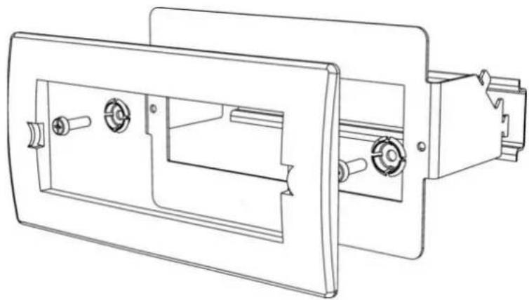
Flush mounted
To flush-mount the meter a flush-mount kit should be used.
Flush-mount kit
The following picture shows a flush-mount kit.
natural_image
Technical line drawing of a mechanical housing or enclosure component (no text or symbols)2.2 Environmental Considerations
Ingress protection
To comply with the protection requirements the product must be mounted in protection class IP 51 enclosures, or better, according to IEC 60259.
Mechanical environment
In accordance with the Measuring Directive (2014/32/UE), the product complies with M2, which means that it can be operated in “...locations with significant or high levels of vibration and shock, e.g. transmitted from machines and passing vehicles in the vicinity or adjacent to heavy machines, conveyor belts, etc.”
Electromagnetic environment
In accordance with the Measuring Directive (2014/32/UE), the product complies with E2, which means that it can be operated “...in locations with electromagnetic disturbances corresponding to those likely to be found in other industrial buildings.”
Climatic environment
In order to work properly the product should not be operated outside the specified temperature range of -40^ - +70^ .
In order to work properly the product should not exposed to humidity exceeding the specified 75% yearly average, 95% on 30 days/year.
2.3 Installing the Meter

Warning – Electrical equipment should only be installed, accessed, serviced and maintained by qualified electrical personnel.
Working with high voltage is potentially lethal. Persons subjected to high voltage may suffer cardiac arrest, burn injuries, or other severe injuries. To avoid such injuries, make sure to disconnect the power supply before you start the installation.

Warning – For safety reasons it is recommended that the equipment is installed in a way that makes it impossible to reach or touch the terminal blocks by accident.
The best way to make a safe installation is to install the unit in an enclosure. Further, access to the equipment should be limited through use of lock and key, controlled by qualified electrical personnel.

Warning – The meters must always be protected by fuses on the incoming side. In order to allow for maintenance of transformer rated meters, it is recommended that there should be a short circuiting device installed near the meter. Alternatively a CT with short circuiting terminals is used to short circuit the secondary current during maintenance. The reason for short circuiting the secondary current during maintenance is that a very high voltage will be induced across the terminals if current is flowing through the CT primary and any secondary terminal is disconnected. This high voltage can be potentially lethal and can damage the CT or other equipment.
Utilization category IEC 62052-31
A41: Utilization Category UC2
A42: Utilization Category UC1

Installation requirements
Meters with wireless communication should not be installed closer than 20 cm from people.
Install the meter
Follow the steps in the table below to install and verify the installation of the meter:
| Step Action | |
| 1 Switch | off the mains power. |
| 2 Place | the meter on the DIN rail and make sure it snaps onto it. |
| 3 Strip | the cable insulation to the length that is indicated on the meter. |
| 4 Connect | the cables according to the wiring diagram that is printed on the meter and tighten the screws (3.0 Nm for direct connected meters and 1.5 Nm for transformer connected meters). |
| 5 | Install the circuit protection. See table 2:1 below for the correct fuse. |
| 6 If inputs | outputs are used, connect the cables according to the wiring diagram that is printed on the meter and tighten the screws (0.25 Nm). Then connect to an external power supply (max 240V). |
| 7 If communication | is used, connect the cables according to the wiring diagram that is printed on the meter and tighten the screws (0.25 Nm). |
| Verify the installation | |
| 8 | Check that the meter is connected to the specified voltage and that voltage phase connections and the neutral (if used) are connected to the correct terminals. |
| 9 For a transformer connected meter, check that the current direction of the primary and secondary current of the external transformer is correct. Also check that the transformer are connected to the correct meter terminals. | |
| 10 Switch on the power. If a warning symbol is displayed, refer to the error codes in Troubleshooting. | |
| 11 | Under the menu item "Instantaneous Values" on the meter, check that the voltage, current, power and power factor are reasonable and that the power direction is what to be expected (the total power should be positive for a load that consumes energy). When doing the check the meter should be connected to the intended load, with a current above zero to make the check as complete as possible. |
Circuit protection
Use the information in this table to select the correct fuse for the circuit protection.
Tabelle: 2:1
| Meter type Max circuit protection | |
| Direct connected 80 A MCB, C | characteristic or 80 A fuse type gL-gG |
| Transformer connected 10 A MCB, B | characteristic or Diazed, fast. |
2.3.1 Configuring the meter
Default settings
For information about how to change the default settings of the meter, refer to the chapter called Meter Settings.
Default settings
The following table lists the default settings of the meter that normally need to be changed. Check the settings of the meter to see if they need to be reconfigured.
| Parameter Direct connected meters Transformer | connected meters |
| Clock --- --- | |
| Ratios VT --- 1 | |
| Ratios CT --- 1 | |
| Pulse frequency | 100 impulses / kWh (kvarh) |
| Pulse length | 100 ms |
2.4 Wiring Diagrams
General

This section describes how to connect the different types of meters to an electricity network. The terminal numbers in the wiring diagrams listed below correspond to the marking on the terminal block of the meter.
2.4.1 Direct connected meters
2-wire connection
The following diagram shows a 2-wire connection of a direct connected 1-phase meter:
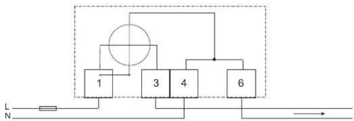
flowchart
graph TD
    A["1"] --> B["3"]
    B --> C["4"]
    C --> D["6"]
    D --> E["Output"]
    F["L"] --> G["Resistor"]
    H["N"] --> I["Ground"]
2.4.2 Transformer connected meters without voltage transformer
2-wire connection
The following diagram shows a 2-wire connection of a transformer connected 3-phase meter:

flowchart
graph TD
    A["Component 1"] --> B["Component 2"]
    B --> C["Component 3"]
    C --> D["Component 5"]
    E["P1"] --> F["Ground"]
    G["S1"] --> H["P1"]
    I["S2"] --> J["P2"]
    style A fill:#f9f,stroke:#333
    style B fill:#ccf,stroke:#333
    style C fill:#cfc,stroke:#333
    style D fill:#fcc,stroke:#333
    style E fill:#ffc,stroke:#333
    style F fill:#cfc,stroke:#333
    style G fill:#fcc,stroke:#333
    style H fill:#cfc,stroke:#333
    style I fill:#fcc,stroke:#333
    style J fill:#cfc,stroke:#333
2.4.3 Transformer connected meters with voltage transformer
2-wire connection
The following diagram shows a 2-wire connection of a transformer connected 3-phase meter with voltage transformers:

flowchart
graph TD
    A["Component 1"] --> B["Component 2"]
    B --> C["Component 3"]
    C --> D["Component 5"]
    E["Power Supply L"] --> F["P1"]
    G["Power Supply N"] --> H["P1"]
    I["S1"] --> J["P1"]
    K["S2"] --> L["P2"]
2.4.4 Inputs/outputs
2 outputs, 2 inputs

flowchart
graph TD
    A["13 15 16"] --> B["Out1"]
    A --> C["Out2"]
    A --> D["Inp1 Inp2"]
    E["17"] --> F["Output"]
    G["18"] --> H["Output"]
    I["●"] --> J["Switch"]
    K["●"] --> L["Switch"]
    M["□"] --> N["Output"]
4 configurable inputs/outputs

flowchart
graph TD
    A["13 15 16"] --> B[" "]
    B --> C["17"]
    C --> D["18"]
    E["C"] --> A
    F["I/O1 I/O2 I/O3 I/O4"] --> B
    G["↔"] --> H["↔"]
    I["↔"] --> J["↔"]
    K["↔"] --> L["↔"]
1 output

flowchart
graph TD
    A["C"] --> B["13"]
    B --> C["Out1"]
    C --> D["15"]
    D --> E["NC"]
    E --> F["NC"]
    F --> G["NC"]
2.4.5 Communication
RS-485
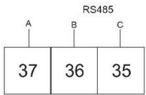
bar
RS485 | Category | Value | |---|---| | A | 37 | | B | 36 | | C | 35 |M-Bus
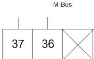
bar
| Category | Value | |---|---| | M-Bus | 37 | | M-Bus | 36 | | X | 36 |Chapter 3: User Interface
Overview
This chapter describes the different display views and the menu structure.
In this chapter
The following topics are covered in this chapter:
3.1 Display 26
3.1 Display
General
The display contains two main views, the Default menu and the Main menu. Use the Exit button ☐ to toggle between the views. In both views a number status icons are displayed in the upper part of the display. These icons are explained in table 3:1 below. In the same manner the bottom part of the display has an explanatory text to describe what is shown or highlighted at the moment.
Default menu
The following image shows an example of the layout of the Default menu:

Energy values
The following table explains the content of the 25 available pages in the Default menu:
| Page Unit Text on display Explaining text | |||
| 1/25 kWh ACT | NRG.IMP.TOT Measures the total | imported active energy. | |
| 2/25 kWh ACT | NRG.EXP.TOT Measures the total | exported active energy. | |
| 3/25 kWh ACT | NRG.NET.TOT Measures the total | net active energy. | |
| 4/25 kvarh REACT.NRG.IMP.TOT Measures the total | imported reactive energy. | ||
| 5/25 kvarh REACT.NRG.EXP.TOT Measures the total | exported reactive energy | ||
| 6/25 kvarh REACT.NRG.NET.TOT Measures the total | net reactive energy | ||
| 7/25 kVAh | APP.NRG.IMP.TOT Measures the total | imported apparent energy | |
| 8/25 kVAh | APP.NRG.EXP.TOT Measures the total | exported apparent energy | |
| Page Unit | Text on | display | Explaining text |
| 9/20 kVAh APP | .NRG.NET.TOT | Measures the total | net apparent energy |
| 10/25 kWh ACT | .NRG.IMP.TAR1 | Measures the im- | ported active energy for tariff 1 |
| 11/25 kWh ACT | .NRG.IMP.TAR2 | Measures the im- | ported active energy for tariff 2 |
| 12/25 kWh ACT | .NRG.IMP.TAR3 | Measures the im- | ported active energy for tariff 3 |
| 13/25 kWh ACT | .NRG.IMP.TAR4 | Measures the im- | ported active energy for tariff 4 |
| 14/25 kWh ACT | .NRG.EXP.TAR1 | Measures the ex- | ported active energy for tariff 1 |
| 15/25 kWh ACT | .NRG.EXP.TAR2 | Measures the ex- | ported active energy for tariff 2 |
| 16/25 kWh ACT | .NRG.EXP.TAR3 | Measures the ex- | ported active energy for tariff 3 |
| 17/25 kWh ACT | .NRG.EXP.TAR4 | Measures the ex- | ported active energy for tariff 4 |
| 18/25 kvarh REACT | .NRG.IMP.TAR1 | Measures the im- | ported reactive en-ergy for tariff 1 |
| 19/25 kvarh REACT | .NRG.IMP.TAR2 | Measures the im- | ported reactive en-ergy for tariff 2 |
| 20/25 kvarh REACT | .NRG.IMP.TAR3 | Measures the im- | ported reactive en-ergy for tariff 3 |
| 21/25 kvarh REACT | .NRG.IMP.TAR4 | Measures the im- | ported reactive en-ergy for tariff 4 |
| 22/25 kvarh REACT | .NRG.EXP.TAR1 | Measures the ex- | ported reactive en-ergy for tariff 1 |
| 23/25 kvarh REACT | .NRG.EXP.TAR2 | Measures the ex- | ported reactive en-ergy for tariff 2 |
| 24/25 kvarh REACT | .NRG.EXP.TAR3 | Measures the ex- | ported reactive en-ergy for tariff 3 |
| 25/25 kvarh REACT | .NRG.EXP.TAR4 | Measures the ex- | ported reactive en-ergy for tariff 4 |
Status Icons
The status icons that can be seen the display are explained in the following table.
Table: 3:1
| Icon Indication | |
| [CS6H] [YC6G] [YXGS] [DKEX] | Active quadrant |
 | Communication is in progress. The meter is either sending or receiving information |
| [2451] | Rotates when metering in progress, that is when the phase current is above the starting current |
 | Arrows indicate direction of current. Arrow left = export, arrow right = import. A digit without arrow indicates that the current is below the starting current |
[HATH]  [8047] T4 [8047] T4 | Active tariff |
| [XYGT] [ZSW6] △ | Error, warning, note |
 | Transformer ratio (only on transformer rated meters) |
Main menu
The following image shows an example of the layout of the main menu:

Main menu icons
Depending on the meter type all or a subset of the following icons may be available in the display:
| Icon Explanation | |
 | Energy registers |
 | Instantaneous values |
 | Stored values |
 | Harmonics |
 | I/O |
| Status | |
 | Settings |
Main menu structure
The following table describes the main menu structure and its content. Depending on meter type, all or a subset of the items can be present.
 |  |  |  |  |  |  |
| Active Energy Import | Active Power Previous | Values THD Voltage I/O 1 System Log Clock | ||||
| Active Energy Export | Reactive Power Load | Profiles Harmonics Voltage | I/O 2 Event Log Ratios | |||
| Active Energy Net Apparent Power Demand | THD Current I/O 3 Net Quality | Log | Wires | |||
| Reactive Energy Import | Phase Voltage | Harmonics Current | I/O 4 System Status | System Status | Pulse Output | |
| Reactive Energy Export | Main Voltage | Audit Log I/O | ||||
| Reactive Energy Net | Current | Settings Log | Alarm | |||
| Apparent Energy Import | frequency | About | Currency/ CO_2 | |||
| Apparent Energy Export | Power Factor | RS-485 | ||||
| Apparent Energy Net | Phase Angle Power | IR Side | ||||
| Active Energy Import Tariff | Phase Angle Voltage | Wireless | ||||
| Active Energy Export Tariff | Phase Angle Current | Upgrade Consent | ||||
| Reactive Energy Import Tariff | Current Quadrant | Pulse LED | ||||
| Reactive Energy Export Tariff | Tariff | |||||
| Resettable Active Energy Import Total | Previous Values | |||||
| Resettable Active Energy Export Total | Load profiles | |||||
| Resettable Reactive Energy Import Total | Demand | |||||
| Resettable Reactive Energy Export Total | Resettable registers | |||||
 |  |  |  |  | [DSG3] |  |
| Currency | ||||||
| CO_2 | ||||||
Chapter 4: Meter Settings
Overview
This chapter gives an overview of the meter settings and configuration options.
In this chapter
The following topics are covered in this chapter:
4.1 Settings and Configurations ...... 32
4.1.1 Setting Date 32
4.1.2 Setting Time 33
4.1.3 Setting Ratios ...... 33
4.1.4 Setting Pulse Output 33
4.1.5 Setting I/O 34
4.1.6 Setting Alarm 35
4.1.7 Setting Currency/CO2 36
4.1.8 Setting M-Bus 36
4.1.9 Setting RS-485 37
4.1.10 Setting IR Side 37
4.1.11 Setting Upgrade Consent 39
4.1.12 Setting Pulse LED 39
4.1.13 Setting Tariff 39
4.1.14 Setting Previous Values 40
4.1.15 Setting Load Profile 40
4.1.16 Setting Demand 41
4.1.17 Resetting Resettable Registers 41
4.1 Settings and Configurations
Configurable functions
Depending on the meter type, all or a subset of the following functions can be configured:
• C l o c k
- Ratios
- W i r e s
- Pulse output (Pul.Out.) on display
• I/O
• A l a r m
• Currency/CO _2 (Curr/CO2) on display
• M - B u s
• R S - 4 8 5
- IR Side
- Wireless (W-less on display)
- Upgrade Consent (Upgr.Cons) on display
- Pulse LED (Puls.LED) on display
- Tariff
- Previous Values (Prev. Val. on display)
- Load profile (Load Pro on display)
- Demand
- Resettable registers (Rst.Rg on display)
Setting a value
When setting a value, the SET button is used to activate the set-option. The ▼ and ▲ buttons are used to change the options that can be set, such as on or off. If the set-option involves setting a number, for example a alarm limit, the ▲ button is used to increase a digit, and the ▼ button is used to decrease a digit. The OK button is used to toggle between digits. The option/digit that is active for setting is marked with a underscore. When the underscore on the last option has disappeared, the setting has been performed.
4.1.1 Setting Date
To set the date, perform the following steps:
-
Choose the Settings icon in the main menu, press OK.
-
Choose "Clock", press OK.
-
The display will now show the date.
-
Set the date.
4.1.2 Setting Time
To set the time, perform the following steps:
- Choose the Settings icon in the main menu, press OK.
- Choose "Clock", press OK.
- The display will now show the date. Press ▼ to get to the time-menu.
- Set the time.
4.1.3 Setting Ratios
To set the ratios, perform the following steps:
- Choose the Settings icon in the main menu, press OK.
- Choose "Ratios", press OK.
- The display will show the quantity Current (CT on the display) and the ratio. To change the ratio, press SET. See table 4:1 for interval.
- Press ▼. The display will show the quantity Voltage (VT on the display) and the ratio. To change the ratio, press SET. See table 4:1 for interval.
Table: 4:1
| Option Interval | |
| Transformer Current (CT) 1-9999/1-9 | |
| Transformer Voltage (VT) 1-999999/1 | -999 |
4.1.4 Setting Pulse Output
To set the pulse output, perform the following steps:
- Choose the Settings icon in the main menu, press OK.
- Choose "Pulse out" (Pul.out on the display), press OK.
The display will show what type of energy is measured on pulse output 1. Depending on meter type, the available choices are:
| Act.Nrg.Imp on the display Active energy imported | |
| Act.Nrg.Exp on the display Active energy exported | |
| React.Nrg.Imp on the display Reactive energy imported | |
| React.Nrg.Exp on the display Reactive energy exported | |
| Inactive on the display Inactive | |
- Set the energy type.
- Press ☑ once to get to the next menu. The display will show the frequency. The intervall that can be set is 0-999999 imp/kWh or 0-999999 imp/MWh. Set the frequency and quantity.
- Press ☑ once to get to the next menu. The display will show the pulse length in milliseconds. The intervall for the pulse length is from 10 to 990ms. Set the pulse length.
- Press ☑ once to get to the next menu. The display will show the setting for pulse output 1. Depending on the meter type, the available choices are:
| 4 configurable I/Os 4 static I/Os 1 static I/O | ||
| No output No output No output | ||
| Out 1 Out 1 Out 1 | ||
| Out 2 Out 2 - | ||
| Out 3 -- | ||
| Out 4 -- |

Note – If choosing an I/O that is not pulse output configured, the option is set to “no output” when pressing the OK button.
- The first pulse output is now fully configured. Depending on the meter type, up to four pulse outputs can be set. If your meter supports multiple pulse outputs, use ☑ to toggle down to the remaining pulse outputs and set them the same way as pulse output 1.
4.1.5 Setting I/O
To set the I/O, perform the following steps:
-
Choose the Settings icon in the main menu, press OK.
-
Choose "I/O", press OK.
-
The display will now show I/O 1. To change I/O, use ▲ or ▼. To set an I/O, press the SET button. Depending on the meter type, different choices can be made for the I/O, see table 4:2.
Table: 4:2
| I/O Available choices | |
| 4 configurable I/Os | • Input• A l a r m o u t• Communication out (Comm.out on display)• Pulse out (Pul.out on display)• Tariff out1• Always on• Always off |
| 4 static I/Os^2 | • Alarm out• Communication out (Comm.out on display)• Pulse out (Pul.out on display)• Tariff out3• Always on• Always off |
| 1 static I/O | • Alarm out• Communication out (Comm.out on display)• Pulse out Pul.out on display)• Always on• Always off |
-
This choice makes it possible to control outputs by time.
-
I/O 1 and I/O 2 are set to static output by default. I/O 3 and 4 are set to static output by default and cannot be configured. I/O 3 and I/O 4 are not shown in the display.
- This choice makes it possible to control fixed I/O outputs by time and thus only available in gold meters.
4.1.6 Setting Alarm
To set the alarm, perform the following steps:
- Choose the Settings icon in the main menu, press OK.
- Choose "Alarm", press OK.
- The display will show what quantity shall be measured. Depending on the meter type, different quantities are available. See table 4:3 and table for available quantities and interval/units for the different quantities. Set the desired quantity.
- Press ☑ once to get to the next menu. The display will show what level the alarm will trigger on. Set the alarm level.
- Press ▼ once to get to the next menu. The display will show the time that the measured value has to be higher than the limit set in the previous step in order for the alarm to trigger. Set the time limit.
- Press ☑ once to get to the next menu. The display will show what level the alarm will cease on. Set the alarm level.
- Press ☑ once to get to the next menu. The display will show the time that the measured value has to be lower than the limit set in the previous step in order for the alarm to cease. Set the time limit.
- Press ☑ once to get to the next menu. The display will show if the alarm will be logged or not. The available values are “on” and “off”. Set logging to on or off.
- Press ☑ once to get to the next menu. The display will show what output the alarm is set on (or if no output is set). The available choices are dependent on meter type, see table 4:4.

Note – If choosing an I/O that is not alarm configured, the option will be set to "no output" when pressing the SET button.
- The first alarm is now fully configured. Depending on the meter type, up to four alarms can be set. If your meter supports multiple alarms, use ▼ and ▲ to set the remaining alarms the same way as the first alarm was configured.
Table: 4:3
| Alarm alternatives Interval/Unit | |
| Inactive - | |
| Current L1 0.01-99.99 A/kA | |
| Voltage L1 0.1-999.9 V/kV | |
| Harmonic voltage L1 0 - 999 % | |
| Harmonic current L1 0 - 999 % | |
| Active power total 0-9999 W/kW/MW | |
| Alarm alternatives | Interval/Unit |
| Reactive power total 0-9999 var/kvar/Mvar | |
| Apparent power total 0-9999 VA/kVA/MVA | |
| Power factor total 0.000-0.999 |
Table: 4:4
| 4 configurable I/Os 4 static I/Os 1 static I/O | ||
| No output No output No output | ||
| Out 1 Out 1 | Out 1 | |
| Out 2 Out 2 | ||
| Out 3 | ||
| Out 4 | ||
4.1.7 Setting Currency/CO2
By setting a conversion factor for Currency/CO 2 , kWh is converted to currency and/or kg CO 2 .
To set currency/CO _2 , perform the following steps:
- Choose the Settings icon in the main menu, press OK.
- Choose "Currency/CO2" (Curr/CO2 on the display), press OK.
- The display will show price in currency per unit.
- Press SET to set the conversion factor and the quantity.
- Use ▼ to get to the next page. The page will display the CO_2 emissions in kg per kWh.
- Press SET to set the conversion factor for CO _2 .
4.1.8 Setting M-Bus
To set the wired M-Bus interface, perform the following steps:
- Choose the Settings icon in the main menu, press OK.
- Choose "MBus", press OK.
- Press ☑ once to get to the next menu. The display will show the baudrate. See Table 4:5 for baudrate options. Set baudrate.
- Press ☑ once to get to the next menu. The display will show the address. See Table 4:5 for address range. Set address.
- Press ▼ once to get to the next menu. The display will show the access level. See Table4:5 for options. Set the access level.
- Press ▼ once to get to the next menu. The display will show the Send status info. See Table 4:5 for options. Set the send info status.
- Press ▼ once to get to the next menu. The display will show if the password is to be reset. See Table 4:5 for options. Set the option.
4.1.9 Setting RS-485
The RS-485 uses the EQ-Bus and the Modbus protocol to communicate. To set the RS-485 communication depending on protocol, perform the following steps:
| Step EQ-Bus Modbus | ||
| 1 | Choose the Settings icon in the main menu, press OK. | Choose the Settings icon in the main menu, press OK. |
| 2 | Choose communication interface. Choose communication interface. | |
| 3 | Choose EQ-Bus. Choose Modbus. | |
| 4 Press | once to get to the next menu. The display will show the baudrate. See table Table 4:5 for baudrate options. Set baudrate. | Press once to get to the next menu. The display will show the baudrate. See Table 4:5 for baudrate options. Set baudrate. |
| 5 Press | once to get to the next menu. The display will show the address. See Table 4:5 for address range. Set address. | Press once to get to the next menu. The display will show the address. See Table 4:5 for address range. Set address. |
| 6 Press | once to get to the next menu. The display will show the Oct. TO. See Table 4:5 for options. Set Oct. TO | Press once to get to the next menu. The display will show the Parity. See Table 4:5 for options. Set Parity. |
| 7 Press | once to get to the next menu. The display will show the Inac. TO. See Table 4:5 for options. Set Inac. TO | |
| Press once to get to the next menu. The display will show if the password is to be reset. See Table 4:5 for options. Set the option. | ||
4.1.10 Setting IR Side
The IR Side uses the M-Bus and the EQ-Bus ^i protocol to communicate. To set the IR Side communication depending on protocol, perform the following steps:
| Step M | -Bus EQ-Bus | |
| 1 | Choose the Settings icon in the main menu, press OK. | Choose the Settings icon in the main menu, press OK. |
| 2 | Choose IR Side, press OK. Choose IR Side, press OK. | |
| 3 | Press set and choose M-Bus. | Press set and choose EQ-Bus. |
| 4 Press | once to get to the next menu. The display will show the baudrate. See Table 4:5 for baudrate options. Set baudrate. | Press once to get to the next menu. The display will show the baudrate. See Table 4:5 for baudrate options. Set baudrate. |
i. EQ-Bus is a communication protocol designed for internal communication with ABB meters. The protocol is based on the following IEC standards; 62056-42, 62056-46, 62056-53, 62056-61, 62056-62.
| Step M-Bus EQ-Bus | ||
| 5 Press | once to get to the next menu. The display will show the address. See Table 4:5 for address range. Set address. | Press once to get to the next menu. The display will show the address. See Table 4:5 for address range. Set address. |
| 6 Press | once to get to the next menu. The display will show the access level. See Table 4:5 for options. Set the access level. | Press once to get to the next menu. The display will show the Oct. TO. See Table 4:5 for options. Set Oct. TO. |
| 7 Press | once to get to the next menu. The display will show the Send status info. See Table 4:5 for options. Set the send info status. | Press once to get to the next menu. The display will show the Inac. TO. See Table 4:5 for options. Set Inac. TO. |
| Press once to get to the next menu. The display will show if the password is to be reset. See Table 4:5 for options. Set the option. | Press once to get to the next menu. The display will show password reset option. Set if the password shall be reset or not. | |
| Press once to get to the next menu. The display will show the upgrade mode. See Table 4:5 for options. Set the upgrade mode. | ||
Protocol details
The following table shows the intervals and options for the different protocols:
Table: 4:5
| Protocol Access level | Upgrade mode | Send Status Info | Reset password | Parity B | Baudrate Address Inter | octet timeout (ms) | Inactivity timeout (ms) |
| EQ-Bus (when used through RS-485) | --- | Yes, No | - | 1200, | 16-16381 20 | -2000 | |
| Modbus (when used through RS-485) | - | - | - | None, Odd, Even | 1200, 2400, 4800, 9600, 19200, 38400, 57600, 230400, 250000, 460800 | 1-247 | - |
| Protocol Access level | Upgrade mode | Send Status Info | Reset password | Parity Baudrate | Address Inter | octet timeout (ms) | Inactivity timeout (ms) |
| M-Bus (when used through IR-Side | Open, Pass-word, Closed | Active, Not Active | Al-ways, Never, When not OK | Yes, No - 2400, | 4800, 9600, 19200, 38400 | 1-250 - - | |
| EQ-Bus (when used through IR-Side) | --- Yes, No - 1200, | 2400, 4800, 9600, 19200, 38400, 57600, 115200, 125000, 230400 |
4.1.11 Setting Upgrade Consent
Upgrade Consent can be set to Allowed or Not Allowed. Setting it to Allowed means you agree to updates of the meter. Setting it to Not Allowed means no upgrades will take place.
To set Upgrade Consent, perform the following steps:
- Choose the Settings icon in the main menu, press OK.
- Choose "Upgrade Consent" (Upgr.Cons on the display), press OK.
- Press SET to set Upgrade Consent.
4.1.12 Setting Pulse LED
To set pulse LED, perform the following steps:
- Choose the Settings icon in the main menu, press OK.
- Choose "Pulse LED" (Puls.LED on the display), press OK.
- Press SET to set the type of energy, active or reactive, that the LED shall indicate on.
4.1.13 Setting Tariff
The tariff source can be set to input, clock or communication. To set the tariffs, perform the following steps:
| Step Input | Clock | Communication | |
| 1 | Choose the Settings icon in the main menu, press OK. | Choose the Settings icon in the main menu, press OK. Choose the Settings icon in the main menu, press OK. | |
| 2 | Choose “Tariff”, press OK. | Choose “Tariff”, press OK. Choose “Tariff”, press OK. | |
| Step Input Clock Communication | |||
| 3 Press | set and choose Input. | Press set and choose Clock.If the display says“Config foundNo reset”then reset the configurationby pressing set and choosing“Reset” | Press set andchoose Comm. |
| 4 Use | to toggle to the first configuration. Four configu-rations are available. Set the tariff that shall be active for each configuration. | Press to get to the next page. | The tariff source is now set for commu-nication. |
| 5 - Set | the desired tariffs with | start-time and if the tariff is to be used or not. Up to eight tariff switch times can be set, four for weekdays and four for weekends. Set at least one tariff for weekdays (Mon-Fri) and one for week-ends (Sat-Sun) even if the values are the same | - |
4.1.14 Setting Previous Values
To set set the previous values, perform the following steps:
- Choose the Settings icon in the main menu, press OK.
- Choose “Previous Values” (Prev.Val. on the display), press OK.
- Perform the setting. The options are day, week and month.
- If setting week, use ▼ to go to the next step.
- Set what week-day the snapshot of the values will be taken.
4.1.15 Setting Load Profile
To set the load profile, perform the following steps:
- Choose the Settings icon in the main menu, press OK.
- Choose "Load Profiles" (Load Pro on the display), press OK.
- The first page will show the interval for the quantity active energy imported (Act.Imp.Tot on the display). Up to eight channels (pages) are available to configure, see table below.
| Page Quantity On display Predefined | value | |||
| 1/8 Active Energy Imported total | Act.Imp.Tot | 1 hours | ||
| 2/8 Active Energy Exported Total | Act.Exp.Tot | 1 hours | ||
| 3/8 Reactive Energy Imported Total | React.Imp.Tot | 1 hours | ||
| 4/8 Reactive Energy Exported Total | React.Exp.Tot | 1 hours | ||
| 5/8 Input Counter 1 Inp.Ctr 1 | 1 hours | |||
| 6/8 Input Counter 2 Inp.Ctr 2 | 1 hours | |||
| 7/8 Input | Counter 3 Inp.Ctr 3 1 hours | |||
| 8/8 Input | Counter 4 Inp.Ctr 4 1 hours | |||
4. Configure the desired channels.
When a configuration has been made, a reset may be required in order to perform a new configuration. To reset the intervals, toggle down to the reset page and perform a reset the same way as performing a setting.
4.1.16 Setting Demand
The demand function enables measuring of up to 50 values (channels). Step 1-6 are general for the function and step 7-9 are specific for each channel.
To set the demand, perform the following steps:
- Choose the Settings icon in the main menu, press OK.
- Choose "Demand" (Demand on the display), press OK.
- Set the period. The available choices are day, week and month. If choosing day, the starting point will be now and the ending point will be 00:00. If choosing month, the starting point will be now and the ending point will be the first of next month at 00:00. If choosing week, the starting point will be now and the ending point will be the set day at 00:00. If choosing week, press ▼ to get to the page where the day is set. Press ▼.
- Set the interval that shall be measured. Press ▼ to continue.
- Set the subinterval that shall be measured. Press ▼ to continue.
- Set if the previous settings shall be reset. Press ▼ to continue.
- Set the quantity that shall be measured. Press ▼ to continue.
- Set the demand type. Press ▼ to continue.
- The demand level will be set automatically.
The first channel is now set. To set the next channel, repeat step 3-9. Up to 50 channels can be set.
4.1.17 Resetting Resettable Registers
To reset registers, perform the following steps:
- Choose the Settings icon in the main menu, press OK.
- Choose "Resettable registers" (Rst.Reg on the display), press OK.
- The display will show the different registers to reset. Depending on the meter type, the available choices are:
| Register On the display | |
| Active Energy Imported Total Act.Imp | |
| Active Energy Exported Total Act.Exp | |
| Reactive Energy Imported Total Rea.Imp | |
| Reactive Energy Exported Total Rea.Exp | |
| Reset all All |
- Toggle through the pages and reset the desired registers.
Chapter 5: Technical Description
Overview
This chapter contains technical descriptions of the meter functions. Depending of the meter type, the meter may contain all or a subset of the functions described in this chapter.
In this chapter
The following topics are covered in this chapter:
5.1 Energy Values 44
5.2 Instrumentation 46
5.3 Harmonics 48
5.3.1 Measuring Harmonics 50
5.4 Alarm 52
5.5 Inputs and Outputs ...... 53
5.5.1 Tariff Inputs 53
5.5.2 Pulse Outputs 54
5.6 Internal Clock 56
5.7 Logs 57
5.7.1 System Log 57
5.7.2 Event Log 58
5.7.3 Net Quality Log 59
5.7.4 Audit Log 59
5.7.5 Settings Log 60
5.7.6 Event codes 60
5.8 Demand 62
5.9 Previous Values ...... 64
5.10 Load Profile 66
5.1 Energy Values
| General | The energy values are stored in energy registers. The different energy registers can be divided into:Registers containing active, reactive or apparent energyRegisters containing different tariffs or total sum of all tariffsRegisters containing energy per phase or total sum of all phasesResettable registers (possible to set to zero via buttons or communication command)Registers containing momentary or historical valueThe energy values can be read via communication or directly in the display with the help of the buttons. |
| Primary value | In transformer connected meters with external current transformers, and sometimes also external voltage transformers, the total transformer ratio is taken into account for all energy registers, that is all energy registers store primary values. |
Presentation of register values
In direct connected meters the energy is usually displayed with 7 digits in kWh/kvarh/KVAh with two decimals and displays one decimal less at overflow, that is it changes to one decimal at 100000.0 kWh and to no decimals at 1000000 kWh.
In transformer connected meters where primary values are displayed, the energy values can be rather big when the total transformer ratio is big. Normally the meter automatically adapts the unit and number of decimals displayed to the value.
In case the energy is displayed with fixed units and number of decimals the energy will "roll over" to zeros when the energy is incremented if all nines are displayed. The meter can however contain more digits internally, which can be read out via communication if the meter is equipped with a communication interface. See the example below where the value 2483756 is displayed, while the internal register contains 192483756.6.
Image
The following picture shows a display with fixed unit and numbers of decimals:

5.2 Instrumentation
Instrumentation functions
The following table shows the complete instrumentation functions of the A41/A42 meters. Depending on the meter type all or a subset of the following functions are available.
| Instrumentation A41 A42 | ||
| Active power X X | ||
| Reactive power X X | ||
| Apparent power X X | ||
| Voltage X X | ||
| Current X X | ||
| Frequency X X | ||
| Power factor X X | ||
| Phase angle power X X | ||
| Phase angle voltage X X | ||
| Phase angle current | X X | |
| Current quadrant | X X | |
| THD voltage | X X | |
| Harmonics voltage (number 2-16) | X X | |
| THD current | X X | |
| Harmonics current (number 2-16) | X X |
Accuracy
All instrumentation data accuracy is defined within the voltage range 20 % of the stated nominal voltage and within the current range 5 % of the base current to the maximum current.
The accuracy of all instrumentation data except the frequency and voltage and current phase-angles is the same as the stated energy metering accuracy. The accuracy for the voltage and current phase-angles is 2 degrees and 0.5 % for the frequency.
5.3 Harmonics
General
The presence of harmonics in voltages and currents may cause a number of unwanted problems. This chapter describes the origin of harmonics, how the negative effects of harmonics can be eliminated and how harmonics is measured.
The harmonics data can be read via communication or directly in the display with the help of the buttons.
Generation of harmonics
Generators in the power system produce a nearly pure sinusoidal voltage with a frequency near the stated system frequency, normally 50 or 60 Hz. Linear loads, consisting of pure resistors, capacitors and inductors, draw a pure sinusoidal current if the voltage over the load is pure sinusoidal.
A non-linear load, however, draws non-sinusoidal current resulting in a current consisting of several frequencies. One example of a common non-linear load are power supplies in electronic equipment which normally contains rectifier diodes which rectifies the incoming voltage and charges a capacitor. The power supply only draws current at the top of the sine wave when the rectified voltage exceeds the voltage over the capacitor. Another example of a non linear load is a thyristor controlled load, where the current normally is turned on at the voltage zero crossing and turned off sometimes during the sine wave.
These currents are all non-sinusoidal and can be divided into a fundamental part, which is the same as the mains frequency, and high frequency parts, that is harmonics, which have frequency that are integral multiples of the mains frequency.
Harmonics in the current will in turn cause harmonics in the voltage since the mains wires and the generator have an impedance causing a voltage drop that is proportional to the current. It should also be pointed out that if there is harmonics in the voltage, also a linear load will cause harmonics in the current, that have the same magnitude as the voltage harmonics. However, the origin of harmonics in the voltage are non-linear loads.
Negative effects of harmonics
The presence of harmonics in voltages and currents can cause a number of problems:
- Increased cable losses. At higher frequencies skin and proximity effects increases, resulting in increased losses.
• High current in the neutral wire. - Motor efficiency and product lifetime will decrease if the voltage contain harmonics.
- In transformers, harmonics will cause higher wire, hysteresis and eddy losses, which could result in efficiency losses up to 50% .
- Voltage harmonic can give higher peak voltages (higher crest factor), causing overvoltage protection devices to trip and in worst case destruction of devices.
- Voltage harmonic can result in decreased product lifetime and in worst case destruction of capacitor banks (used for power factor correction).
- Voltage harmonic can cause malfunction of devices controlled by the voltage, often zero crossings (voltage harmonics can give extra zero crossings).
- Voltage harmonics can produce disturbances within devices having its power supply connected to the mains causing problems.
Eliminating negative effects of harmonics
Because of the negative effects of harmonics it may be necessary to take actions to decrease the problems. This can be either done by decreasing the harmonics, and/or taking actions that decrease the negative effects of the harmonics.
Suggested actions
- Increase the size of the neutral conductor if the current is abnormally high due to harmonics.
• Install appropriate filters to isolate loads with high current harmonics. - Install filters to protect to protect loads that are sensitive to voltage harmonics.
- Oversize generators, motors and transformers to better cope with harmonics.
- Substitute equipment for equipment that generates less current harmonics and is less sensitive to voltage harmonics.
5.3.1 Measuring Harmonics
| General | To detect and eliminate the problems related to presence of harmonics, it's generally necessary to measure the harmonics. Meters that have harmonic measurement enabled measure harmonics on all voltages and currents up to the 16th harmonic and calculates the total harmonic distortion (THD). |
| Measuring | Measurement of the harmonics is done sequentially, one at a time, and approximately two harmonic numbers are measured every second.Each harmonic is calculated according to: I_n / I_f · 100% and the total current harmonic distortion for the harmonics measured is calculated according to: _n=2^16 I_n^2 / I_f · 100% where I_f is the fundamental current and I_n is the current for harmonics with number n.At each measurement the harmonic is set to 0 if the rms value of the current is below a certain lower limit (normally 5% of the basic current). |
| Folding distortion | Since the meter have limited sampling frequency, presence of harmonics over the 20:th harmonic (1 kHz at 50 Hz line frequency) will result in folding distortion and can affect the harmonic measurement accuracy negatively.Due to the possible presence of folding distortion and the fact that harmonics is measured sequentially, one at a time, it is recommended that the harmonic measurement results of the meter is used as a tool to detect presence of harmonics and not as an exact instrument to get exact results. |
| Frequency measurement | Measuring harmonics require a valid frequency measurement. If the frequency measurement is uncertain, the harmonic measurement will not be performed. To get a valid measurement the meter uses a retry scheme. If the retry scheme does not give a valid measurement the harmonic will be marked as "not available". |
Accuracy
The accuracy of the current harmonics varies with the harmonic amplitude and is valid only provided there is no harmonics above the 16th harmonic.
| Harmonic Number | 1% < Distortion ≤ 5% | 5% < Distortion ≤ 10% | 10% < Distortion ≤ 20% | 20% < Distortion ≤ 50% | 50% < Distortion ≤ 100% |
| 2 ± 0.5%^* ± 1.0 | ± 2% ± 4% ± 6% | ||||
| 3 ± 0.7%^* ± 1.5% ± 3% ± 6% | ± 9% | ||||
| 4 ± 1.0% ± 2.0% ± 4% ± 8% ± 12% | |||||
| 5 ± 1.2% ± 2.5% ± 5% ± 10% ± 15% | |||||
| 6 ± 1.5% ± 3.0% ± 6% ± 12% ± 18% | |||||
| 7 ± 1.7% ± 3.5% ± 7% ± 14% ± 21% | |||||
| 8 ± 2.0% ± 4.0% ± 8% ± 16% ± 24% | |||||
| 9 ± 2.5% ± 5.0% ± 10% ± 20% ± 30% | |||||
| 10 ± 2.5% ± 5.0% ± 10% ± 20% ± 30% | |||||
| 11 ± 2.5% ± 5.0% ± 10% ± 20% ± 30% | |||||
| 12 ± 2.5% ± 5.0% ± 10% ± 20% ± 30% | |||||
| 13 ± 2.5% ± 5.0% ± 10% ± 20% ± 30% | |||||
| 14 ± 2.5% ± 5.0% ± 10% ± 20% ± 30% | |||||
| 15 ± 2.5% ± 5.0% ± 10% ± 20% ± 30% | |||||
| 16 ± 2.5% ± 5.0% ± 10% ± 20% ± 30% |
* For distortion levels below 1% the absolute uncertainty is ± 0.5%.
5.4 Alarm
General
The purpose of the alarm function is to enable monitoring of quantities in the meter. Monitoring can be set to high or low level detection. High level detection gives an alarm when the level of a quantity goes above the set level. Low level detection gives an alarm when the value goes below the set level.
It is possible to configure 25 alarms. Configuration can be done via communication or with the buttons directly on the meter.
Quantities
Depending on the meter type all or a subset of the following quantities can be monitored:
| Voltage Apparent power | |
| Current Power factor | |
| Active power Harmonic voltage | |
| Reactive power Harmonic current |
Functional description
When the value of the monitored quantity passes the activation level, and remains there for a period of time equal or longer than the specified time delay, the alarm is activated. In the same way, the alarm is deactivated when the value passes the deactivation level and remains there for a time equal or longer than the specified time delay.
If the activation level is higher than the deactivation level, the alarm is activated when the value of the monitored quantity is higher than the activation level.
If the activation level is lower than the deactivation level, the alarm is activated when the vale of the monitored quantity is lower than the activation level.
5.5 Inputs and Outputs
| General | Inputs/outputs are built with optocouplers and are galvanically isolated from other meter electronics. They are polarity independent and handle both DC and AC voltage.An input that is not connected equals having its voltage off.The equivalent circuitry of the outputs is an ideal relay in series with a resistor. |
| Functionality of inputs | The inputs count pulses, register activity and current status and the data can be read directly on the meter display or via communicationRegister activity can be reset via communication or via the buttons directly on the meter. |
| Functionality of outputs | The outputs can be controlled by communication, alarm or by the internal clock. |
5.5.1 Tariff Inputs
| Tariff control | On meters with tariff functionality, the tariffs are controlled either via communication, the internal clock or by 1 or 2 tariff inputs.Tariff control via inputs is done by applying a proper combination of "voltage" or "no voltage" to the input(s). Each combination of "voltage"/"no voltage" will result in that the meter will register the energy in a particular tariff register.In combined meters with both active and reactive metering, both quantities are controlled by the same inputs and the active tariff for active and reactive energy will always be the same. |
| Indication of active tariff | The active tariff is displayed on the LCD by the text "Tx" in the status field, where x is the tariff number. The active tariff can also be read via communication. |
Input coding, meters with 4 tariffs
The coding of the inputs is binary. The following table describes the default coding.
| Input 4 Input 3 Tariff | |
| OFF OFF = T1 | |
| OFF ON = T2 | |
| ON OFF = T3 | |
| ON ON = T4 |
Input coding, meters with 2 tariffs
The coding of the inputs is binary. The following table describes the default coding.
| Input 3 Tariff | |
| OFF = T1 | |
| ON = T2 | |
5.5.2 Pulse Outputs
About pulse outputs
Meters equipped with pulse outputs may have up to 4 outputs.
On the pulse outputs the meter sends out a specified number of pulses (pulse frequency) per kWh (kvarh for reactive pulse outputs).
The pulse outputs are primary, which means that the pulses are sent out in proportion to the true primary energy, taking current and voltage transformer ratios (CT and VT ratio) programmed on the meter into account.
For direct connected meters no external transformers are used and the amount of pulses sent out are in proportion to the energy flowed through the meter.
5.5.2.1 Pulse Frequency and Pulse length
General
Pulse frequency and pulse length can be set via the buttons on the meter or via communication. If the meter have more than 1 pulse output, all outputs will have the same pulse frequency and pulse length.
Pulse frequency
The pulse frequency is configurable and can be set to a value between 1-9999 impulses. The value must be an integer. The unit is selectable and may be set to imp/kWh, imp/Wh or imp/MWh.
Pulse length
The pulse length can be set to a value between 10-990 ms.
Deciding pulse frequency/length
If the power is too high for a certain pulse length and pulse frequency, there is a risk that the pulses may go into one another. If this happens the meter will emit a new pulse (relay closed) before the previous one has terminated (relay open) and the pulse will be missed. In worst case the relay may be closed at all times.
To avoid this problem a calculation should be made to work out the maximum pulse frequency allowed at a particular site based upon an estimated maximum power and the meter's pulse output data.
Formula
The formula to use for this calculation is:
Max pulse frequency = 1000*3600 / U / I / n / (Ppause + Plength)
where U and I is the estimated maximum element voltage (in volts) and current (in amperes), n the number of elements (1 - 3). Plength and Ppause are the pulse length and the required pulse pause (in seconds). A reasonable minimum pulse length and pulse pause is 30 ms which conforms to the S0 and IEC standard.

Note - U and I have to be the primary values in a transformer connected meter if the CT and VT for the external transformers are programmed into the meter.
Example 1
In a direct connected 3-element meter with estimated maximum voltage and current of 250 V and 65 A and pulse length 100 ms and required pulse pause 30 ms, the maximum allowed pulse frequency will be:
1000 * 3600 / 250 / 65 / 3 / (0.030 + 0.100)) = 568 impulses / kWh (kvarh)
Example 2
In a transformer connected 3-element meter with estimated maximum voltage and current of 63 × 100 V = 6300 V (VT ratio 100) and 6 × 50 A = 300 A (CT ratio 50) and pulse width 100 ms and required pulse pause 30 ms the maximum allowed pulse frequency will be:
1000 * 3600 / 6300 / 300 / 3 / (0.030 + 0.100) = 6.16 impulses / kWh (kvarh)
5.6 Internal Clock
| General | Meter with a built-in clock automatically keeps track of leap year and daylight savings time (DST). The use of DST is optional.Time is controlled by a quartz crystal real time clock. |
| Time and date | Time and date can be set via communication, or with the buttons directly on the meter. |
| Time dependant functions | Load profileMaximum demandMinimum demandPrevious valuesEvent logOutputs controlled by timeTariff control |
| Backup of clock | In case of power failure a super capacitor backs up the clock for at least 48 hours. |
5.7 Logs
General
The meter contains a total of five different logs:
- System Log
- Event Log
- Net Quality Log
- Audit log
- Settings Log
Log events can be read via communication or directly in the display of the meter.
A maximum of 500 log events can be stored in the System Log, the Event Log and the Net Quality Log. When the maximum number of events for a log is reached, the oldest events will be overwritten.
A maximum of 40 log events can be stored in the Audit Log. When the maximum number of events for this log is reached, no more events can be stored. A new firmware upgrade attempt will be unsuccessful because no more log events can be stored.
A maximum of 80 log events can be stored in the Settings Log. When the maximum number of events for this log is reached, no more events can be stored. A new setting for either CT/VT or number of elements will not be accepted because no more log events can be stored.
It is possible to delete all entries in the System Log, The Event Log and the Net Quality Log via communication.
5.7.1 System Log
This log stores events that relate to errors in the meter.
Contents
The following information is stored in an event:
- Date and time
- Event Code
- Duration
The following events are stored in this log:
- Program CRC Error - Error when checking firmware consistency.
- Persistent Storage Error - Data stored in long-term memory is corrupt.
- RTC Circuit Error - Error when trying to read date and time from real-time clock.
5.7.2 Event Log
This log stores events that relate to alarms and configuration warnings.
Contents
The following information is stored in an event:
- Date and Time
- Event Code
- Duration
The following events are stored in this log:
- Date Not Set Warning - Date has not been configured for RTC.
- Time Not Set Warning - Time has not been configured for RTC.
- Negative Total Power - Power is measured as negative.
- Alarm Current
- Alarm Active Power
- Alarm Reactive Power
- Alarm Apparent power
- Alarm Power Factor
5.7.3 Net Quality Log
This log stores alarms and information that relates to net quality.
Contents
The following events are stored in this log
• Voltage Missing Warning - Voltage is missing
- Frequency Warning - Net frequency is not stable
- Alarm Voltage
- Alarm Harmonic Voltage
5.7.4 Audit Log
The Audit Log stores an event after an attempt has been made to upgrade the firmware.
Contents
The following information is stored in an event:
- Date and Time
- Firmware version
• Active Energy import
• Active Energy import Tariff 1
• Active Energy import Tariff 2
• Active Energy import Tariff 3
• Active Energy import Tariff 4
• Active Energy Export - Firmware Upgrade status
5.7.5 Settings Log
This log stores an event when the transformer ratio is reconfigured.
Contents
The following information is stored in an event:
- Date and Time
- Firmware version
• Active Energy import
• Active Energy import Tariff 1
• Active Energy import Tariff 2
• Active Energy import Tariff 3
• Active Energy import Tariff 4
• Active Energy Export
• C T - V a l u e
• V T - V a l u e
5.7.6 Event codes
Description
The following table describes the event codes that may occur in the System log, the Event log and the Net quality log:
| Event code Event |
| 41 Program CRC error |
| 42 Persistent storage error |
| 53 RTC circuit error |
| 1000 Voltage Missing Warning |
| 1004 Negative Power Element 1 Warning |
| 1007 Negative Total power Warning |
| 1008 Frequency Warning |
| 1010 Date Not Set Warning |
| 1011 Time Not Set Warning |
| 2013 Alarm 1 active |
| 2014 Alarm 2 active |
| 2015 Alarm 3 active |
| 2016 Alarm 4 active |
| 2017 Alarm 5 active |
| 2018 Alarm 6 active |
| 2019 Alarm 7 active |
| 2020 Alarm 8 active |
| 2021 Alarm 9 active |
| 2022 Alarm 10 active |
| 2023 Alarm 11 active |
| 2024 Alarm 12 active |
| 2025 Alarm 13 active |
| 2026 Alarm 14 active |
| 2027 Alarm 15 active |
| 2028 Alarm 16 active |
| 2029 Alarm 17 active |
| 2030 Alarm 18 active |
| 2031 Alarm 19 active |
| 2032 Alarm 20 active |
| 2033 Alarm 21 active |
| 2034 Alarm 22 active |
| 2035 Alarm 23 active |
| 2036 Alarm 24 active |
| 2037 Alarm 25 active |
5.8 Demand
General
The demand functionality is used to measure and store the maximum and minimum demands of different quantities in the meter. Time is divided into intervals of a certain length in which the mean values of a set of selected quantities are measured.
Demand can be configured via Modbus and EQ-bus communication or via the buttons on the meter.

Note – Before any demand values can be stored, time/date must be set.
Changing time/ date will store the current period and start a new one.
If a power fail occurs that lasts over the end of an ongoing period, the period will be stored when the meter powers up again and a new period will start. If date/time is not set when the meter powers up again, demand will enter a waiting state until time/date is set.
Interval length
The interval lengths for demand can be one of the following: 1, 2, 5, 10, 15, 20, 30, 60 minutes.
Storing periods
When the last interval of an ongoing period has finished, the maximum- and/or minimum values are stored and a new period starts.
The length of a demand period can be a day, a week or a month.
Demand has 50 channels which can be configured individually. Each channel can store up to 200 periods. A stored period contains the demand value, the date/time of the period and the date/time of the interval when the demand value was measured. All channels use the same interval, subinterval and period length. Individual channel parameters are type of demand which have the four choices maximum, minimum, maximum sliding or minimum sliding and the number of the demand with the three choices first, second or third (max/min).
The period/interval date and time is stored as end of period/interval. For instance, if a period starts 2010.01.01 00:00.00 and ends 2010.01.02 00:00.00, then the stored period will be 2010.01.02 00:00.00.
If there is no free memory space available, the oldest period will be erased to make room for the most recent one.
Stored periods can be read via communication or directly on the display.
An ongoing period can be ended and a new one started by sending a “freeze demand” via communication.
It is also possible to erase all stored periods by sending a “Reset Demand” command via communication.
If the time is set backward within an interval the calculation of demand for that interval is restarted if the channel is configured to store a maximum value (as the
| actual time for that interval will be longer than the interval time which could result in a too big demand value). For the same reason the calculation of demand for an interval is restarted if the channel is configured to store a minimum value and the time is set forward within the interval or into another interval. | ||
| Demand values | Each demand quantity is individually configurable to store up to the three highest or lowest demand values, where each value use one demand channel configured to use first, second and third maximum/minimum. If demand is configured to store only one maximum interval, then only the interval with the maximum peak will be recorded. If a demand quantity is configured to store three maximum intervals the intervals with the three highest peaks are recorded. | |
| Sliding demand | A demand channel can also be configured as maximum sliding demand or minimum sliding demand. A sub-interval time is set which divides the interval into a circular array with a new mean value calculated at the end of every sub-interval. The selectable sub-interval times for demand is a subset of the interval times and evenly divisible with the selected interval time. | |
| Selectable quantities | Depending on the meter type all or a subset of the following quantities can be selected. | |
| ACTIVE POWER IMPORT TOTAL REACTIVE POWER IMPORT TARIFF2 | ||
| REACTIVE POWER IMPORT TOTAL REACTIVE POWER IMPORT TARIFF3 | ||
| APPARENT POWER IMPORT TOTAL REACTIVE POWER IMPORT TARIFF4 | ||
| ACTIVE POWER IMPORT TARIFF1 VOLTAGE L1 | ||
| ACTIVE POWER IMPORT TARIFF2 HARMONIC VOLTAGE L1 | ||
| ACTIVE POWER IMPORT TARIFF3 CURRENT L1 | ||
| ACTIVE POWER IMPORT TARIFF4 HARMONIC CURRENT L1 | ||
| REACTIVE POWER IMPORT TARIFF1 PULSE INPUT COUNTERS | ||
| The value is the mean value of the interval. The unit for the pulse input counters are pulses per hour (for example if 2 pulses were registered in a 15 minute interval the value for the interval will be 8 pulses per hour). | ||
5.9 Previous Values
General
At the end of a defined period, up to 50 configurable channels, which can contain energy register values, input counter values and currency/CO _2 values, are stored together with the time/date for the end of the period.
Previous values can be configured via Modbus and EQ-bus communication or via the buttons on the meter.

Note – Before any previous values can be stored, time/date must be set.
Changing time/date into another period than the pending period will store the current period and start a new one.
If a power fail occurs that lasts over the end of an ongoing period, the period will be stored when the meter powers up again and a new period will start. If the meter have lost time and date/time is not set when the meter powers up again, previous values will enter a waiting state until time/date is set.
Storing periods
Previous values has 50 channels which can be configured individually via communication. Each channel can store up to 200 periods.
The period length can be a day, a week or a month and can be configured via Modbus and EQ-bus communication or via the buttons on the meter.
The period date and time is stored as end of period. For instance, if a period starts 2010.01.01 00:00.00 and ends 2010.01.02 00:00.00, then the stored period will be 2010.01.02 00:00.00.
Stored periods can be read via communication or directly on the display.
If there is no free memory space available, the oldest period will be erased to make room for the most recent one.
It is possible to erase all stored periods by sending a “Reset Previous Values” command via communication.
Selectable quantities
Depending on the meter type all or a subset of the following quantities can be selected.
| ACTIV ENERGY IMPORT TOTAL ACTIVE | ENERGY EXPORT TARIFF1 |
| ACTIVE ENERGY EXPORT TOTAL ACTIVE | ENERGY EXPORT TARIFF2 |
| REACTIVE ENERGY IMPORT TOTAL ACTIVE | ACTIVE ENERGY EXPORT TARIFF3 |
| REACTIVE ENERGY EXPORT TOTAL ACTIVE | ACTIVE ENERGY EXPORT TARIFF4 |
| APPARENT ENERGY IMPORT TOTAL RE | ACTIVE ENERGY EXPORT TARIFF1 |
| APPARENT ENERGY EXPORT TOTAL RE | ACTIVE ENERGY EXPORT TARIFF2 |
| RESETTABLE ACTIVE ENERGY IMPORT TOTAL | REACTIVE ENERGY EXPORT TARIFF3 |
| RESETTABLE ACTIVE ENERGY EXPORT TOTAL | REACTIVE ENERGY EXPORT TARIFF4 |
| RESETTABLE REACTIVE ENERGY IMPORT TOTAL | ACTIVE ENERGY NET TOTAL |
| RESETTABLE REACTIVE ENERGY EXPORT TOTAL | REACTIVE ENERGY NET TOTAL |
| ACTIVE ENERGY IMPORT TARIFF1 APPARENT ENERGY NET TOTAL | |
| ACTIVE ENERGY IMPORT TARIFF2 ACTIVE ENERGY CURRENCY CONVERSION | |
| ACTIVE ENERGY IMPORT TARIFF3 ACTIVE ENERGY CO2 CONVERSION | |
| ACTIVE ENERGY IMPORT TARIFF4 PULSE INPUT COUNTERS | |
| REACTIVE ENERGY IMPORT TARIFF1 | |
| REACTIVE ENERGY IMPORT TARIFF2 | |
| REACTIVE ENERGY IMPORT TARIFF3 | |
| REACTIVE ENERGY IMPORT TARIFF4 | |
5.10 Load Profile
| General | Load profile is a collection of 8 channels that can store register values for register quantities or interval averages for instrumentation quantities. Through Modbus and EQ-bus communication each channel can be assigned one register or instrumentation quantity, a time interval and a maximum amount of snapshots to be stored in the channel.Interval length per channel can also be configured via the buttons on the meter.The load profiles can be read via communication or directly on the display.The stored register values in a channel are read as a list of register snapshots and for instrumentation values as a list of interval averages.Note – Before any load profiles can be stored, time/date must be set.If a power failure occurs that lasts over the end of an interval, the value will be stored when the meter powers up again only if time/date are still correct. |
| Intervals | The interval lengths for Load Profiles can be one of the following: 1, 2, 5, 10, 15, 20, 30, 60, 120, 180, 240, 360, 480, 720 or 1440 minutes.If the interval is evenly divisible with an hour, the start of each hour will mark the start of a new interval. If the interval is evenly divisible with a day, the start of a day will mark the start of a new interval.The interval date and time is stored as end of interval. For instance, if an interval starts 2010.01.01 00:00.00 and ends 2010.01.01 00:15.00, then the stored period will be 2010.01.01 00:15.00. |
| Example 1 | Interval is set to 120 minutes, current time 12:13. Evenly divisible with a day. The next interval end/start times will be: 14:00, 16:00, 18:00, 20:00, 22:00, 00:00, etc,... |
| Example 2 | Interval is set to 15 minutes, current time 12:13. Evenly divisible with an hour. The next interval end/start times will be: 12:15, 12:30, 12:45, 13:00, 13.15, 13.30 etc,... |
| Channels and snapshots | Each channel has its own interval configuration. That means that snapshots in one channel can be stored with a different interval than snapshots in another channel. Each channel can be assigned a number of snapshots. A total of 40 000 snapshots can be stored in a load profile. All channels in a load profile share the same memory area, which means that one channel can store 40 000 snapshots if no other |
channel is used. By default the meter has all 8 channels activated with 5000 snapshots assigned to each.
If there is no free memory space available, the oldest snapshot will be erased to make room for the most recent one.
It is possible to erase all snapshots in all channels by sending a “Reset Load profile” command via communication. Via Modbus and EQ-bus communication it is also possible to erase all snapshots in a particular channel.
Load profile data
Each load profile data value is associated with a status value. The status value gives information such as:
- Interval is longer or shorter than defined length
• Power outage occurred during interval - Overflow in data
• Time was changed during interval - Data not available
- Error in data
Selectable quantities
Depending on the meter type all or a subset of the following quantities can be selected:
| ACTIVE ENERGY IMPORT TOTAL ACTIVE | ENERGY CURRENCY CONVERSION |
| ACTIVE ENERGY EXPORT TOTAL ACTIVE | ENERGY CO2 CONVERSION |
| REACTIVE ENERGY IMPORT TOTAL | VOLTAGE L1* |
| REACTIVE ENERGY EXPORT TOTAL CURRENT | L1* |
| APPARENT ENERGY IMPORT TOTAL POWER FACTOR TOTAL* | |
| APPARENT ENERGY EXPORT TOTAL PULSE INPUT COUNTERS | |
*The values are mean values of the intervals.
Chapter 6: Technical data
Overview
This chapter contains technical data and product drawings.
In this chapter
The following topics are covered in this chapter:
6.1 Technical Specifications 68
6.2 Physical dimensions 72
6.1 Technical Specifications
Specifications for A41 direct connected meters
| Voltage/current inputs | |
| Nominal voltage 230 V AC | |
| Voltage range 57.7 - 288 V AC (-20%-+15%) | |
| Power dissipation voltage circuits 0.8 VA (0.8 W) at 230 V AC | |
| Power dissipation current circuits 0.007 | VA (0.007 W) at I ref |
| Base current Ib | 5 A |
| Reference current Iref | 5 A |
| Transitional current Itr | 0.5 A |
| Maximum current Imax | 80 A |
| Minimum current Imin | 0.25 A |
| Starting current Ist | < 20 mA |
| Terminal wire area 1-25 mm | 2 |
| Recommended tightening torque 3.0 Nm | |
| General data | |
| Frequency 50 or 60 Hz ± 5% | |
| Accuracy 1%, 2% | |
| Accuracy of internal clock 5 ppm at reference temperature 25°C | |
| Display 96x64 pixels, view area 39x26 mm | |
| Mechanical | |
| Material Polycarbonate in transparent front glass, bottom case, upper case and terminal cover. Glass reinforced polycarbonate in terminal block. | |
| Weight 0.23 kg | |
| Environmental | |
| Operating temperature | -40°C - +70°C |
| Storage temperature | -40°C - +85°C |
| Humidity | 75% yearly average, 95% on 30 days/year |
| Resistance to fire and heat | Terminal 960°C, cover 650°C (IEC 60695-2-1) |
| Resistance to water and dust | IP 20 on terminal block without protective enclosure and IP 51 in protective enclosure, according to IEC 60529. |
| Mechanical environment | Class M2 in accordance with the Measuring Instrument Directive (MID), (2014/32/UE). |
| Electromagnetic environment | Class E2 in accordance with the Measuring Instrument Directive (MID), (2014/32/UE). |
| Outputs | |
| Current | 2 - 100 mA |
| Voltage | 5 - 240 V AC/DC. For meters with only 1 output, 5 - 40 V DC. |
| Pulse output frequency | Prog. 1 - 9999 imp/MWh, 1 - 9999 imp/kWh, 1 - 9999 imp/Wh |
| Pulse length | 10 - 990 ms |
| Terminal wire area 0.5 - 1 mm2 | |
| Recommended tightening torque 0.25 Nm | |
| Inputs | |
| Voltage 0-240 V AC/DC | |
| Off 0-5 V AC/DC | |
| ON 57-240 V AC, 24-240 V DC | |
| Min. pulse length and pulse pause 30 ms | |
| Terminal wire area 0.5 - 1 mm2 | |
| Recommended tightening torque 0.25 Nm | |
| Communication | |
| Terminal wire area 0.5 - 1 mm2 | |
| Recommended tightening torque 0.25 Nm | |
| M-Bus EN 13757-2, EN 13757-3 | |
| Modbus Modbus Application Protocol Specification V1.1b | |
| EQ-Bus IEC 62056-42, 62056-46, 62056-53, 62056-61, 62056-62 | |
| Pulse indicator (LED) | |
| Pulse Frequency 1000 imp/kWh | |
| Pulse length 40 ms | |
| EMC compatibility | |
| Impulse voltage test 6 kV 1.2/50μs (IEC 60060-1) | |
| Surge voltage test 4 kV 1.2/50μs (IEC 61000-4-5) | |
| Fast transient burst test | 4 kV (IEC 61000-4-4) |
| Immunity to electromagnetic HF-fields | 80 MHz - 2 GHz at 10 V/m (IEC 61000-4-3) |
| Immunity to conducted disturbance | 150kHz - 80MHz, (IEC 61000-4-6) |
| Immunity to electromagnetic disturbances | 2-150 kHz for kWh-meters |
| Radio frequency emission | EN 55022, class B (CISPR22) |
| Electrostatic discharge | 15 kV (IEC 61000-4-2) |
| Standards | IEC 62052-11, IEC 62053-21 class 1 & 2, IEC 62053-23 class 2, IEC 62054-21, GB/T 17215.211-2006, GBT 17215.321-2008 class 1 & 2, GB 4208-2008, EN 50470-1, EN 50470-3 category A & B |
Specifications for A42 transformer connected meters
| Voltage inputs | |
| Nominal voltage | 230 V AC |
| Voltage range | 57.7 - 288 V AC (-20% - + 15%) |
| Power dissipation voltage circuits | 0.8 VA (0.8 W) at 230 V AC |
| Power dissipation current circuits | 0.001 VA (0.001 W) at I_ref |
| Terminal wire area 0.5 - 10 mm ^2 | |
| Recommended tightening torque 1.5 Nm | |
| Current inputs | |
| Rated current I_n | 1 A |
| Reference current I_ref | 1 A |
| Maximum current I_max | 6 A |
| Transitional current I_tr | 0.05 A |
| Minimum current I_min | 0.01 A |
| Starting current I_st | < 1 mA |
| Terminal wire area 0.5 - 10mm | 2 |
| Recommended tightening torque 1.5 Nm | |
| General data | |
| Frequency 50 or 60 Hz ± 5% | |
| Accuracy 0.5%, 1% | |
| Accuracy of internal clock 5 ppm at reference temperature 25°C | |
| Display 96x64 pixels, view area 39x26 mm | |
| Mechanical | |
| Material Polycarbonate in transparent front glass, bottom case, upper case and terminal cover. Glass reinforced polycarbonate in terminal block. | |
| Weight 0.20 kg | |
| Environmental | |
| Operating temperature -40°C - +70°C | |
| Storage temperature -40°C - +85°C | |
| Humidity 75% yearly average, 95% on 30 days/year | |
| Resistance to fire and heat | Terminal 960°C, cover 650°C (IEC 60695-2-1) |
| Resistance to water and dust | IP 20 on terminal block without protective enclosure and IP 51 in protective enclosure, according to IEC 60529. |
| Mechanical environment | Class M2 in accordance with the Measuring Instrument Directive (MID), (2014/32/UE). |
| Electromagnetic environment | Class E2 in accordance with the Measuring Instrument Directive (MID), (2014/32/UE). |
| Outputs | |
| Current | 2 - 100 mA |
| Voltage | 5-240 V AC/DC. For meters with only 1 output, 5 - 40 V DC. |
| Pulse output frequency | Prog. 1 - 9999 imp/MWh, 1 - 9999 imp/kWh, 1 - 9999 imp/Wh |
| Pulse length | 10 - 990 ms |
| Terminal wire area 0.5 - 1 mm2 | |
| Recommended tightening torque 0.25 Nm | |
| Inputs | |
| Voltage | 0-240 V AC/DC |
| Off | 0-5 V AC/DC |
| ON | 57-240 V AC, 24-240 V DC |
| Min. pulse length and pulse pause | 30 ms |
| Terminal wire area 0.5 - 1 mm2 | |
| Recommended tightening torque 0.25 Nm | |
| Communication | |
| Terminal wire area 0.5 - 1 mm | |
| Recommended tightening torque 0.25 Nm | |
| M-Bus EN 13757-2, EN 13757-3 | |
| Modbus Modbus Application Protocol Specification V1.1b | |
| EQ-Bus IEC 62056-42, 62056-46, 62056-53, 62056-61, 62056-62 | |
| Transformer ratios | |
| Configurable voltage ratio (VT) 1 - 9999 | |
| Configurable current ratio (CT) 1 - 9999 | |
| Max total transformer ratio (VT*CT) 999999 | |
| Pulse indicator (LED) | |
| Pulse Frequency 5000 imp/kWh | |
| Pulse length 40 ms | |
| EMC compatibility | |
| Impulse voltage test 6 kV 1.2/50μs (IEC 60060-1) | |
| Surge voltage test 4 kV 1.2/50μs (IEC 61000-4-5) | |
| Fast transient burst test 4 kV (IEC 61000-4-4) | |
| Immunity to electromagnetic HF-fields | 80 MHz - 2 GHz at 10 V/m (IEC61000-4-3) |
| Immunity to conducted disturbance | 150kHz – 80MHz, ( IEC 61000-4-6 ) |
| Immunity to electromagnetic disturbances | 2-150 kHz for kWh-meters |
| Radio frequency emission | EN 55022, class B (CISPR22) |
| Electrostatic discharge | 15 kV (IEC 61000-4-2) |
| Standards | IEC 62052-11, IEC 62053-21 class 1 & 2, IEC 62053-23 class 2, IEC 62054-21, GB/T 17215.211-2006, GBT 17215.321-2008 class 1 & 2, GB 4208-2008, EN 50470-1, EN 50470-3 category A & B |
6.2 Physical dimensions
A41/A42
The following drawing shows the physical dimensions of the A41 and the A42 meters.


natural_image
Technical line drawing of a mechanical housing or enclosure with mounting brackets and internal compartments (no text or symbols)
Chapter 7: Measurement Methods
Overview
This chapter contains information about measurement theory and the most commonly used measurement methods. The information can be used to better understand the meter behavior and/or to pick the correct measurement method.
In this chapter
The following topics are covered in this chapter:
7.1 Measuring Energy 74
7.1.1 Single Phase, 1-Element Metering 76
7.1 Measuring Energy
Active energy
It is easy to understand the need for a utility to measure active energy, since the information is necessary to bill the customer correctly. Usually the more energy the customer consumes the higher the accuracy of the meter needs to be. Normally 4 accuracy classes are used: 2%- (small consumers, e.g. households), 1%-, 0.5%- and 0.2%-meters with defined power levels for each class.
Also from a customer point of view it is easy to understand the need to measure the active energy as it can give him information about where and when energy is consumed. This information can then be used to take measures to decrease the consumption.
In many cases it is desired to simplify the measurement. In such cases simplified methods can be used of which the most common are described in this chapter. These methods most often require a balanced load, which means that the impedance is the same in all phases giving the same current amplitude and power factor in all phases.
Reactive energy
Sometimes there is also a need to measure the reactive energy. Consumer equipment often introduces a phase shift between current and voltage due to the fact that the load has a more or less reactive component, e.g. motors that have an inductive component, etc. A reactive load will increase the current which means that the power source generator and the size of the power lines have to increase which in turn means higher cost for the utility. A higher current also means that the line losses increase.
Because of that, the maximum permissible phase shift is sometimes governed in the terms of the contract that the consumer have with the power supplier. If the consumer exceeds a specified maximum reactive load, he will be liable for an extra charge. This type of contract will require a utility meter that measures reactive energy and/or power.
Also, from the customer's point of view, it may be of some interest to measure reactive energy/power since it gives him knowledge about the nature of the load. That is, how big the different loads are and how they vary over time. This knowledge can be used in the planning how to decrease the reactive power/energy to decrease the electricity bill.
Resistive, inductive and capacitive loads
Resistive loads don't give rise to any phase shifts. Inductive loads have phase shift in one direction with the current lagging the voltage, while capacitive loads produces a phase shift in the opposite direction with the current leading the voltage. As a result, inductive and capacitive loads can be used to compensate each other
Illustration
The following illustration shows a vector diagram for resistive, inductive and capacitive loads:
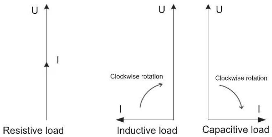
Phase displacement
A load that consumes both reactive and active energy can be divided into active and reactive components. The angle between the apparent power (U*I) vector and the active power component is described as phase displacement angle or power factor angle, often referred to as . Cos is referred to as the power factor.
Illustration
The following illustration shows a vector diagram for a load with an active and a reactive component:
| Active power = P = U x I x cos φ (unit W) |
| Reactive power = Q = U x I x sin φ (unit var) |
| Apparent power = S = U x I (unit VA) |
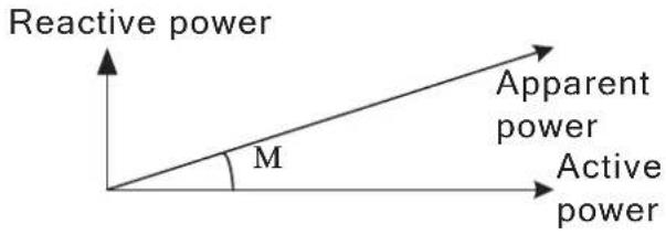 |
The 4 power quadrants
The type of load can be represented geometrically by for quadrants. In the first quadrant the load is inductive and active and energy is imported (energy is delivered from the utility to the customer). In the second quadrant the load is capacitive and active energy is exported and reactive energy is imported. In the third quadrant the load is inductive and active and reactive energy is exported. In the last quadrant the load is capacitive and active energy is imported and reactive energy exported.
Illustration
The following illustration shows the loads

7.1.1 Single Phase, 1-Element Metering
1-element metering in a 2-wire system
In a 2-wire installation a single phase meter is used. Normally the 2 wires are a phase voltage and the neutral.
The active energy consumed by the load is the product of momentary voltage and current integrated over the desired measuring time period.
Calculating active power
In the case where no harmonics is present and the rms value of the voltage and current is constant, the active power can be expressed as:
$$ \mathrm{P} = \mathrm{U} _ {\mathrm{rms}} * \mathrm{I} _ {\mathrm{rms}} * \cos \varphi $$
where is the phase angle between the voltage and the current.
Illustration
The following illustration shows a direct connected single phase meter measuring the active energy (E) consumed by a load.

1-element metering in a 4-wire system
In 4-wire system the single element metering method only gives correct results in a balanced system (same voltage, current and power factor in all phases). This method should not be used for accurate measurement, but can be used when high accuracy is not needed.
Illustration
The following illustration shows single phase metering in a 3-phase system.
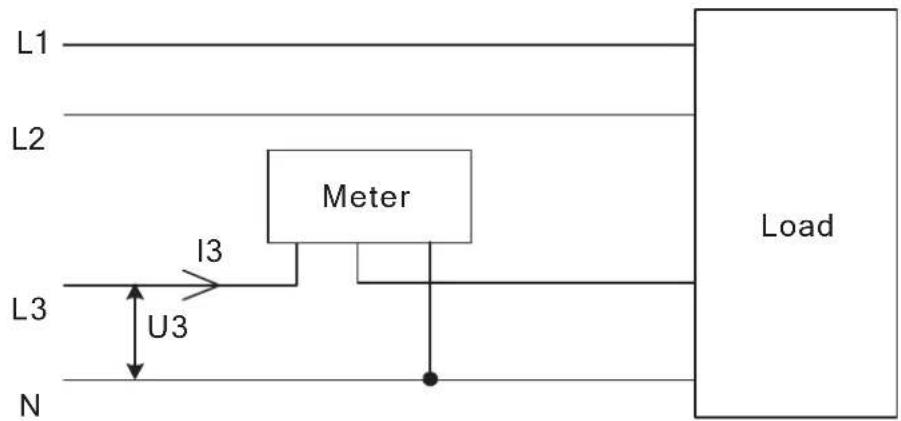
Summation metering
The currents from several different transformers can be summed into one single meter.
Illustration
The following illustration shows summation metering in a single phase meter:

Chapter 8: Service & Maintenance
Overview
This chapter contains information about service and maintenance of the product.
In this chapter
The following topics are covered in this chapter:
8.1 Service and Maintenance 80
8.1 Service and Maintenance
| Service | This product contains no parts that can be repaired or exchanged. A broken meter must be replaced. |
| Cleaning | If the meter needs to be cleaned, use a lightly moistened cloth with a mild detergent to wipe it. |
| Caution – Be careful that no liquid gets into the meter since it can ruin the equipment. |
Chapter 9: Communication with Modbus
Overview
This chapter describes the mapping from meter data to Modbus and how to read and write to registers. The chapter contains information for all functionality and data for the complete A series family. For single phase meters some data does not exist, for example data for phase 2 and 3.
In this chapter
The following topics are covered in this chapter:
9.1 Bus Description 82
9.2 About the Modbus Protocol 83
9.2.1 Function Code 3 (Read holding registers 83
9.2.2 Function Code 16 (Write multiple registers) 85
9.2.3 Function Code 6 (Write single register) 86
9.3 Reading and Writing to Registers 88
9.5 Historical Data 100
9.5.1 Quantity identifiers 103
9.6 Previous Values ...... 108
9.6.1 Reading Previous Values 110
9.7 Demand 112
9.7.1 Reading Demand 114
9.8 Event logs 116
9.8.1 Reading Event logs 118
9.9 Load profile 119
9.9.1 Reading Load profile 121
9.10 Configuration 122
9.10.1Previous values 122
9.1 Bus Description
General Modbus communication in the A series meters is done on a 3-wire (A, B and
Common) polarity dependent bus according to the RS-485 standard. Maximum number of meters connected to one physical bus is 247 (which is the same as the individual device address range in Modbus).
Topology
The RS-485 bus uses line topology, see figure below. Stubs at the meter connections are allowed but should be kept as short as possible and no longer than 1 m. Bus termination in both ends of the line should be used. The resistors should have the same values as the characteristic impedance of the cable which normally is 120 ohm.
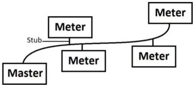
Cable used is non shielded or shielded twisted pair cable with wire area of 0.35-1.5 mm ^2 . If shielded cable is used the shield should be connected to ground in one end. Maximum length of the bus is 700 m.
9.2 About the Modbus Protocol
| General | Modbus is a master-slave communication protocol that can support up to 247 slaves organized as a multidrop bus. The communication is half duplex. Services on Modbus are specified by function codes.The function codes are used to read or write 16 bit registers. All metering data, such as active energy, voltage or firmware version, is represented by one or more such registers. For further information about the relation between register number and metering data, refer to “Mapping Tables” on page - 89.The Modbus protocol is specified in its entirety in Modbus Application Protocol Specification V1.1b. The document is available at http://www.modbus.org | |||
| Supported function codes | The following function codes are supported:Function code 3 (Read holding registersFunction code 6 (Write single register)Function code 16 (Write multiple registers) | |||
| Modbus request frame | A Modbus request frame generally has the following structure: | |||
| Slave Address Function | Code Data Error Check | |||
| Slave address Modbus | slave address, 1 byte. | |||
| Function code Decides | the service to be performed. | |||
| Data Dependent on the function code. The length varies. | ||||
| Error check CRC, 2 bytes | ||||
| Message types | The network messages can be query-response or broadcast type. The query-response command sends a query from the master to an individual slave and is generally followed by a response.The broadcast command sends a message to all slaves and is never followed by a response. Broadcast is supported by function code 6 and 16. | |||
9.2.1 Function Code 3 (Read holding registers
General Function code 3 is used to read measurement values or other information from the electricity meter. It is possible to read up to 125 consecutive registers at a time. This means that multiple values can be read in one request.
Request frame
A request frame has the following structure:
| Slave Address Function Code Address | No. of Registers Error Check |
Example of a request
The following is an example of a request. (read total energy import, etc...)
| Slave address 0x01 | |
| Function code 0x03 | |
| Start address, high byte 0x50 | |
| Start address, low byte 0x00 | |
| No. of registers, high byte 0x00 | |
| No. of registers, low byte 0x18 | |
| Error check (CRC), high byte 0x54 | |
| Error check (CRC), low byte 0xC0 |
Response frame
A response frame has the following structure:
| Slave Address Function Code Byte Count Register Values Error Check |
Example of a response
The following is an example of a response:
| Slave address | 0x01 |
| Function code | 0x03 |
| Byte count | 0x30 |
| Value of register 0x5000, high byte | 0x00 |
| Value of register 0x5000, low byte | 0x15 |
| ... | |
| Value of register 0x5017, high byte | 0xFF |
| Value of register 0x5017, low byte | 0xFF |
| Error check (CRC), high byte | 0xXX |
| Error check (CRC), low byte | 0xXX |
In this example, the slave with the Modbus address 1 responds to a read request. The number of data bytes is 0x30. The first register (0x5000) has the value 0x0015 and the last (0x5017) has the value 0xFFFF
9.2.2 Function Code 16 (Write multiple registers)
General
Function code 16 is used to modify settings in the meter, such as date/time, to control output and to reset values, such as power fail counter. It is possible to write up to 123 consecutive registers in a single request. This means that several settings can be modified and/or several reset operations can be performed in a single request.
Request frame
A request frame has the following structure:
| Slave Address | Function Code | Start Address | No. of Registers | Byte Count | Register Values | Error Check |
Example of a request
The following is an example of a request (set Date/Time to November 11, 2010, 12:13:14):
| Slave address 0x01 | |
| Function code 0x10 | |
| Start address, high byte 0x8A | |
| Start address, low byte 0x00 | |
| No. of registers, high byte 0x00 | |
| No. of registers, low byte 0x03 | |
| Byte count 0x06 | |
| Value of register 0x8A00, high byte 0x0A | |
| Value of register 0x8A00, low byte 0x0B | |
| Value of register 0x8A01, high byte 0x0B | |
| Value of register 0x8A01, low byte 0x0C | |
| Value of register 0x8A02, high byte 0x0D | |
| Value of register 0x8A02, low byte 0x0E | |
| Error check (CRC), high byte 0x8C | |
| Error check (CRC), low byte 0x82 |
In this example the master sends a write request to the slave that has the Modbus address 1. The first register to write is 0x8A00 and the number of registers to write is 0x03. This means that the registers 0x8A00 to 0x8A02 are written. Register 0x8A00 is set to the value 0x0A0B, and so on.
Response frame
A response frame has the following structure:
Slave Address Function Code Start Address No. of Registers Error Check
Example of a response
The following is an example of a response:
| Slave address 0x01 | |
| Function code 0x10 | |
| Register address, high byte 0x8A | |
| Register address, low byte 0x00 | |
| No. of registers, high byte 0x00 | |
| No. of registers, low byte 0x03 | |
| Error check (CRC), high byte 0xAA | |
| Error check (CRC), low byte 0x10 |
In the example above the slave with the Modbus address 1 responds to a write request. The first register is 0x8A00 and 0x03 registers have been successfully written to.
9.2.3 Function Code 6 (Write single register)
General
Function code 6 can be used as an alternative to function code 16 if there is only one register to be written. It can, for example be used to reset the power fail counter.
Request frame
A request frame has the following structure:
Slave Address Function Code Register Address Register Value Error Check
Example of a request
The following is an example of a request (reset power fail counter):
| Slave address | 0x01 |
| Function code | 0x06 |
| Register address, high byte | 0x8F |
| Register address, low byte | 0x00 |
| No. of registers, high byte | 0x00 |
| No. of registers, low byte | 0x01 |
| Error check (CRC), high byte 0x62 | |
| Error check (CRC), low byte 0xDE |
Response frame
Using function code 6, the response frame is an echo of the request frame.
9.2.3.1 Exception Responses
General
If an error should occur while processing a request, the meter gives an exception response that contains an exception code.
Exception frame
An exception frame has the following structure:
| Slave Address Function Code Exception | Code Error Check |
In the exception response the function code is set to the function code of the request plus 0x80.
Exception codes
The exception codes that are used are listed in the following table:
| Exception code Exception Definition | ||
| 01 | Illegal function | A function code that is not supported has been used. |
| 02 Illegal data address | The requested register is outside the allowed range. | |
| 03 Illegal data value | The structure of a received message is incorrect. | |
| 04 Slave device failure | Processing the request fail due to an internal error in the meter. | |
9.3 Reading and Writing to Registers
| Readable registers | The readable range in the modbus mapping are registers 1000-8EFF (hexadecimal). Reading any registers within this range will result in a normal Modbus response. It is possible to read any number of registers between 1 and 125, i.e., it is not necessary to read all registers of a quantity listed on one line in the mapping tables. Any attempt to read outside this range will result in an illegal data address exception (Modbus exception code 2). |
| Multi-register values | For quantities that are represented as more than 1 register, the most significant byte is found in the high byte of the first (lowest) register. The least significant byte is found in the low byte of the last (highest) register. |
| Unused registers | Unused registers within the mapping range, for example missing quantities in the connected meter, will result in a normal Modbus response but the value of the register will be set to “invalid”.For quantities with data type “unsigned”, the value will be FFFF in all registers. For quantities with data type “signed”, the value is the highest value possible to express. That means that a quantity that is represented by only one register will have the value 7FFF. A quantity that is represented by 2 registers will have the value 7FFFFFFF, and so on. |
| Writing to registers | Writing to registers is only permitted to the registers listed as writable in the mapping tables. Attempting to write to a register that is listed as writable but that is not supported by the meter will not result in an error indication.Note - It is not possible to modify parts of a setting, e.g. to set only the year and month of the Date/time setting. |
| Confirm set values | After you set a value in the meter, it is recommended that you read the value to confirm the result, since it is not possible to confirm if a write was successful from the Modbus response. |
9.4 Mapping Tables
Introduction
The purpose of this section is to explain the relation between register number and metering data.
Contents of the mapping tables
The following table explains the content of the mapping tables:
| Quantity Name of the meter | meter quantity or other information available in the meter. |
| Details Refinement of the | the Quantity column. |
| Start Reg (Hex) Hexadecimal number for the first (lowest) Modbus Register for this quantity. * | |
| Size Number of Modbus registers for the meter Quantity. A Modbus Register is 16 bits long. | |
| Res. Resolution of the value for this Quantity (if applicable). | |
| Unit Unit for the Quantity (if applicable). | |
| Data type Data type for this Quantity, i.e. how the value in the Modbus registers should be interpreted. | |
*It is expressed exactly as it is sent on the bus. That is, it should not be subtracted by 40 000 or decremented by 1, as is common for Modbus products.
Total energy accumulators
All registers in the following table are read only:
| Quantity Details | Start reg | (Hex) | Size Res. Unit | Data type | ||
| Active import | kWh | 5000 | 4 | 0,01 | kWh | Unsigned |
| Active export | kWh | 5004 | 4 | 0,01 | kWh | Unsigned |
| Active net | kWh | 5008 | 4 | 0,01 | kWh | Signed |
| Reactive import | kvarh | 500C | 4 | 0,01 | kvarh | Unsigned |
| Reactive export | kvarh | 5010 | 4 | 0,01 | kvarh | Unsigned |
| Reactive net | kvarh | 5014 | 4 | 0,01 | kvarh | Signed |
| Apparent import | kVAh | 5018 | 4 | 0,01 | kVAh | Unsigned |
| Apparent export | kVAh | 501C | 4 | 0,01 | kVAh | Unsigned |
| Apparent net | kVAh | 5020 | 4 | 0,01 | kVAh | Signed |
| Active import CO2 | kVAh | 5024 | 4 | 0,001 | kg | Unsigned |
| Active import Currency | kVAh | 5034 | 4 | 0,001 | currency | Unsigned |
Energy accumulators divided into tariffs
All registers in the following table are read only:
| Quantity Details | Start reg (Hex) | Size Res. Unit | Data type | ||
| Active import Tariff | 1 5170 4 0,01 kWh Unsigned | ||||
| Active import Tariff | 2 5174 4 0,01 kWh Unsigned | ||||
| Active import Tariff | 3 5178 4 0,01 kWh Unsigned | ||||
| Active import Tariff | 4 517C 4 0,01 kWh Unsigned | ||||
| Active export Tariff | 1 5190 4 0,01 kWh Unsigned | ||||
| Active export Tariff | 2 5194 4 0,01 kWh Unsigned | ||||
| Active export Tariff | 3 5198 4 0,01 kWh Unsigned | ||||
| Active export Tariff | 4 519C 4 0,01 kWh Unsigned | ||||
| Reactive import Tariff | 1 51B0 4 0,01 kvarh Unsigned | ||||
| Reactive import Tariff | 2 51B4 4 0,01 kvarh Unsigned | ||||
| Reactive import Tariff | 3 51B8 4 0,01 kvarh Unsigned | ||||
| Reactive import Tariff | 4 51BC 4 0,01 kvarh | Unsigned | Unsigned | ||
| Reactive export Tariff | 1 51D0 4 0,01 kvarh Unsigned | ||||
| Reactive export Tariff | 2 51D4 4 0,01 kvarh Unsigned | ||||
| Reactive export Tariff | 3 51D8 4 0,01 kvarh Unsigned | ||||
| Reactive export Tariff | 4 51DC 4 0,01 kvarh | Unsigned |
Energy accumulators per phase
All registers in the following table are read only:
| Quantity Details | Start reg (Hex) | Size Res. Unit | Data type | ||
| Active import L1 | 5460 | 4 0,01 kWh Unsigned | |||
| Active import L2 | 5464 | 4 0,01 kWh Unsigned | |||
| Active import L3 | 5468 | 4 0,01 kWh Unsigned | |||
| Active export L1 | 546C | 4 0,01 kWh Unsigned | |||
| Active export L2 | 5470 | 4 0,01 kWh Unsigned | |||
| Active export L3 | 5474 | 4 0,01 kWh Unsigned | |||
| Active net | L1 | 5478 4 0,01 kWh | Signed | ||
| Active net | L2 | 547C 4 0,01 kWh | Signed | ||
| Active net | L3 | 5480 4 0,01 kWh | Signed |
| Quantity | Details | Start reg (Hex) | Size | Res. | Unit | Data type |
| Reactive import L1 | 5484 4 0,01 | kvarh Unsigned | ||||
| Reactive import L2 | 5488 4 0,01 | kvarh Unsigned | ||||
| Reactive import L3 | 548C 4 0,01 | kvarh Unsigned | ||||
| Reactive export L1 | 5490 4 0,01 | kvarh Unsigned | ||||
| Reactive export L2 | 5494 4 0,01 | kvarh Unsigned | ||||
| Reactive export L3 | 5498 4 0,01 | kvarh Unsigned | ||||
| Reactive net L1 549 | C 4 0,01 kvarh Signed | |||||
| Reactive net L2 54A | A0 4 0,01 kvarh Signed | |||||
| Reactive net L3 54A | 4 4 0,01 kvarh Signed | |||||
| Apparent import L1 | 54A8 4 0,01 kVAh Unsigned | |||||
| Apparent import L2 | 54AC 4 0,01 kVAh Unsigned | |||||
| Apparent import L3 | 54B0 4 0,01 kVAh Unsigned | |||||
| Apparent export L1 | 54B4 4 0,01 kVAh Unsigned | |||||
| Apparent export L2 | 54B8 4 0,01 kVAh Unsigned | |||||
| Apparent export L3 | 54BC 4 0,01 kVAh Unsigned | |||||
| Apparent net L1 54 | C0 4 0,01 kVAh Signed | |||||
| Apparent net L2 54 | C4 4 0,01 kVAh Signed | |||||
| Apparent net L3 54 | C8 4 0,01 kVAh Signed |
Resettable energy accumulators
All registers in the following table are read only:
| Quantity | Start reg (Hex) | Size | Res. | Unit Data type |
| Resettable active import | 552C | 4 0,01 | kWh | Unsigned |
| Resettable active export | 5530 | 4 0,01 | kWh | Unsigned |
| Resettable reactive import | 5534 | 4 0,01 | kWh | Unsigned |
| Resettable reactive export | 5538 | 4 0,01 | kWh | Unsigned |
Instantaneous values
All registers in the following table are read only:
| Quantity Details Start | reg (Hex) | Size Res. Unit Value range Data | type | ||||
| Voltage L1-N 5B00 2 0,1 V Unsigned | |||||||
| Voltage L2-N 5B02 2 0,1 V Unsigned | |||||||
| Voltage L3-N 5B04 2 0,1 V Unsigned | |||||||
| Voltage L1-L2 5B06 2 0,1 V Unsigned | |||||||
| Voltage L3-L2 5B08 2 0,1 V Unsigned | |||||||
| Voltage L1-L3 5B0A 2 0,1 V Unsigned | |||||||
| Current L1 5B0C 2 0,01 A Unsigned | |||||||
| Current L2 5B0E 2 0,01 A Unsigned | |||||||
| Current L3 5B10 2 0,01 A Unsigned | |||||||
| Current N 5B12 2 0,01 A Unsigned | |||||||
| Active power | Total | 5B14 | 2 | 0,01 | W | Signed | |
| Active power | L1 5B16 | 2 0,01 | W | Signed | |||
| Active power | L2 5B18 | 2 0,01 | W | Signed | |||
| Active power | L3 5B1A | 2 0,01 | W | Signed | |||
| Reactive power | Total | 5B1C | 2 | 0,01 | var | Signed | |
| Reactive power | L1 | 5B1E | 2 | 0,01 | var | Signed | |
| Reactive power | L2 | 5B20 | 2 | 0,01 | var | Signed | |
| Reactive power | L3 | 5B22 | 2 | 0,01 | var | Signed | |
| Apparent power | Total | 5B24 | 2 | 0,01 | VA | Signed | |
| Apparent power | L1 5B26 | 2 0,01 | VA | Signed | |||
| Apparent power | L2 5B28 | 2 0,01 | VA | Signed | |||
| Apparent power | L3 5B2A | 2 0,01 | VA | Signed | |||
| Frequency | 5B2C 1 | 0,01 | Hz | Unsigned | |||
| Phase angle power | Total | 5B2D | 1 | 0,1 | ° | -180°-+180° | Signed |
| Phase angle power | L1 | 5B2E | 1 | 0,1 | ° | -180°-+180° | Signed |
| Phase angle power | L2 | 5B2F | 1 | 0,1 | ° | -180°-+180° | Signed |
| Phase angle power | L3 | 5B30 | 1 | 0,1 | ° | -180°-+180° | Signed |
| Phase angle voltage L1 5B31 1 | 0,1° | -180°-+180° | S | Signed | |||
| Phase angle voltage L2 5B32 1 | 0,1° | -180°-+180° | S | Signed | |||
| Phase angle voltage L3 5B33 1 | 0,1° | -180°-+180° | S | Signed | |||
| Phase angle current | L1 | 5B37 | 1 | 0,1 | ° | -180°-+180° | Signed |
| Phase angle current | L2 | 5B38 | 1 | 0,1 | ° | -180°-+180° | Signed |
| Phase angle current | L3 | 5B39 | 1 | 0,1 | ° | -180°-+180° | Signed |
| Power factor | Total | 5B3A | 1 | 0,001 | - | -1,000-+1,000 | Signed |
| Power factor | L1 | 5B3B | 1 | 0,001 | - | -1,000-+1,000 | Signed |
| Power factor | L2 | 5B3C | 1 | 0,001 | - | -1,000-+1,000 | Signed |
| Quantity | Details | Start reg (Hex) | Size | Res. | Unit | Value range | Data type |
| Power factor L3 5B3D | 1 0,001 | -1,000- | +1,000 | Signed | |||
| Current quadrant Total | 5B3E 1 | - 1-4 Unsigned | |||||
| Current quadrant L1 5B3F | 1 | - 1-4 Unsigned | |||||
| Current quadrant L2 5B40 | 1 | - 1-4 Unsigned | |||||
| Current quadrant L3 5B41 | 1 | - 1-4 Unsigned | |||||

Note - Powers are sent out as 32 bit signed integers, expressed in W (or var/VA) with 2 decimals. This means that the maximum power possible to express is approximately ± 21 MW. If the power is higher than that the user is advised to read power from the DMTME mapping instead, where the scaling is in W without decimals.
Harmonics
Harmonics are mapped in one register each, starting with THD and then followed by 2nd, 3rd, 4th harmonic and so on.
All registers in the following table are read only:
| Quantity | Details | Start reg (Hex) | Size/ harmonic | Nr of harmonics | Res. | Unit | Data type |
| Voltage harmonics | L1-N | 5D00 | 1 | 16 | 0,1 | % | Unsigned |
| Voltage harmonics | L2-N | 5D80 | 1 | 16 | 0,1 | % | Unsigned |
| Voltage harmonics | L3-N | 5E00 | 1 | 16 | 0,1 | % | Unsigned |
| Voltage harmonics | L1-L2 | 5E80 | 1 | 16 | 0,1 | % | Unsigned |
| Voltage harmonics | L3-L2 | 5F00 | 1 | 16 | 0,1 | % | Unsigned |
| Voltage harmonics | L1-L3 | 5F80 | 1 | 16 | 0,1 | % | Unsigned |
| Current harmonics | L1 | 6000 | 1 | 16 | 0,1 | % | Unsigned |
| Current harmonics | L2 | 6080 | 1 | 16 | 0,1 | % | Unsigned |
| Current harmonics | L3 | 6100 | 1 | 16 | 0,1 | % | Unsigned |
| Current harmonics | N | 6180 | 1 | 16 | 0,1 | % | Unsigned |
Inputs and outputs
The following table contains both writable and read only registers:
| Quantity | Details | Start Reg (Hex) | Size | Possible values | Data type | Read/Write |
| Output 1 | 6300 | 1 | ON=1, OFF=0 | Unsigned | R/W |
| Quantity Details Start | Reg (Hex) | Size Possible values Data type Read/Write | |||
| Output 2 630 | 1 1 ON=1, OFF=0 Unsigned R/W | ||||
| Output 3 630 | 2 1 ON=1, OFF=0 Unsigned R/W | ||||
| Output 4 630 | 3 1 ON=1, OFF=0 Unsigned R/W | ||||
| Input 1 Current state 6308 1 | ON=1, OFF=0 Unsigned R | ||||
| Input 2 Current state 6309 1 | ON=1, OFF=0 Unsigned R | ||||
| Input 3 Current state 630A 1 | ON=1, OFF=0 Unsigned R | ||||
| Input 4 Current state 630B 1 | ON=1, OFF=0 Unsigned R | ||||
| Input 1 Stored state 6310 1 | ON=1, OFF=0 Unsigned R | ||||
| Input 2 Stored state 6311 1 | ON=1, OFF=0 Unsigned R | ||||
| Input 3 Stored state 6312 1 | ON=1, OFF=0 Unsigned R | ||||
| Input 4 Stored state 6313 1 | ON=1, OFF=0 Unsigned R | ||||
| Input 1 Counter 6318 4 Unsigned R | |||||
| Input 2 Counter 631C 4 Unsigned R | |||||
| Input 3 Counter 6320 4 Unsigned R | |||||
| Input 4 Counter 6324 4 Unsigned R | |||||
Production data and identification
All registers in the following table are read only:
| Quantity | Start Reg (Hex) | Size Data type |
| Serial number | 8900 | 2 Unsigned |
| Meter firmware version 8908 | 8 ASCII string (up to 16 characters) | |
| Modbus mapping version 8910 | 1 2 bytes | |
| Type designation | 8960 | 6 ASCII string (12 characters, including null termination) |
Meter firmware version is expressed as a string of 3 digits separated by periods, e.g. 1.0.0. Unused bytes at the end are set to binary 0.
In the Modbus mapping version register the high byte corresponds to the Major version (1-255), and the low byte corresponds to the Minor version (0-255).
Miscellaneous
In the following table Date/time and current tariff are writable. All other registers are read only:
| Quantity Start | Reg (Hex) | Description Size | Data type | Read/ | Write |
| Date/time 8A00 Byte 0: | year* | Byte 1: monthByte 2: dayByte 3: hourByte 4: minuteByte 5: second | 3 Date/ | Time R/W | |
| Day of week 8A03 Weekdays (1-7, Mo=1) | 1 Unsigned R | ||||
| DST active 8A04 1=DST active | 0=DST inactive | 1 Unsigned R | |||
| Day type 8A05 Value 0-15 | correspond to day type 1-16 | 1 Unsigned R | |||
| Season 8A06 Value 0-3 | correspond to season 1-4 | 1 Unsigned R | |||
| Current tariff 8A07 Tariff | 1-4 1 Unsigned R/W | ||||
| Error flags | 8A13 | 64 flags | 4 | Bit string | R |
| Information flags | 8A19 | 64 flags | 4 | Bit string | R |
| Warning flags | 8A1F | 64 flags | 4 | Bit string | R |
| Alarm flags | 8A25 | 64 flags | 4 | Bit string | R |
| Power fail counter | 8A2F | 1 Unsigned R | |||
| Power outage time | 8A39 Byte 0-2: days*Byte 3: hoursByte 4: minutesByte 5: seconds | 3 Days/Time R | |||
| Reset counter for active energy import | 8A48 | 4 Unsigned R | |||
| Reset counter for active energy export | 8A4C | 4 Unsigned R | |||
| Reset counter for reactive energy import | 8A50 | 4 Unsigned R | |||
| Reset counter for reactive energy export | 8A54 | 4 Unsigned R | |||
* Byte 0 is the highest byte of the lowest register
The Reset counter registers show the number of times the resettable energy accumulators have been reset.
Settings
All registers in the following table have read and write access except number of elements which is read only:
| Quantity Start | Reg (hex) | Size Res. Unit Data type | |||
| Current transformer ratio primary current | 8C04 2 - Unsigned | ||||
| Voltage transformer ratio primary voltage | 8C06 2 - Unsigned | ||||
| Current transformer ratio secondary current | 8C08 2 - Unsigned | ||||
| Voltage transformer ratio secondary voltage | 8C0A 2 - Unsigned | ||||
| CO2 conversion factor 8CE0 | 2 0.001 kg/kWh Unsigned | ||||
| Currency conversion factor 8 | CE2 2 0.01 | Currency/ | kWh | Unsigned | |
| LED source (0 = active energy, 1 = reactive energy) | 8CE4 1 - Unsigned | ||||
| Number of elements (values 1-3) | 8CE5 1 - Unsigned | ||||
| DST start (month in 8CE6 high byte, day of month in 8CE6 low byte, day of week in 8CE7 high byte, hour in 8CE7 low byte) | 8CE6 2 - Unsigned | ||||
| DST end (month in 8CE6 high byte, day of month in 8CE6 low byte, day of week in 8CE7 high byte, hour in 8CE7 low byte) | 8CE8 2 - Unsigned | ||||
| DST enabled (0 = disabled, 1 = enabled) | 8CEA 1 - Unsigned | ||||
Operations
All registers in the following table are write only:
| Quantity Details Start | Reg (hex) | Size A | Action Data type | ||
| Reset power fail counter | 8F00 1 | Write the | value 1 to perform a reset | Unsigned | |
| Reset power outage time | 8F05 1 | Write the | value 1 to perform a reset | Unsigned | |
| Reset input counter Input | 1 8F0B 1 | Write the | value 1 | to perform a reset | Unsigned |
| Reset input counter Input | 2 8F0C 1 | Write the | value 1 | to perform a reset | Unsigned |
| Reset input counter Input | 3 8F0D 1 | Write the | value 1 | to perform a reset | Unsigned |
| Reset input counter Input | 4 8F0E 1 | Write the | value 1 | to perform a reset | Unsigned |
| Reset stored state input | 1 8F13 1 W | Write the value | value 1 to | perform a reset | Unsigned |
| Reset stored state Input | 2 8F14 1 W | Write the value | value 1 to | perform a reset | Unsigned |
| Reset stored state input | 3 8F15 1 W | Write the value | value 1 to | perform a reset | Unsigned |
| Reset stored state Input | 4 8F16 1 W | Write the value | value 1 to | perform a reset | Unsigned |
| Reset resettable active energy import | 8F1B 1 | Write the | value 1 to perform a reset | Unsigned | |
| Reset resettable active energy export | 8F1C 1 | Write the | value 1 to perform a reset | Unsigned | |
| Reset resettable reactive energy import | 8F1D 1 | Write the | value 1 to perform a reset | Unsigned | |
| Reset resettable reactive energy export | 8F1E 1 | Write the | value 1 to perform a reset | Unsigned | |
| Reset Previous values | 8F1F 1 Write the value 1 to | perform a reset | Unsigned | ||
| Reset Demand 8F20 1 Write the value 1 to | perform a reset | Unsigned | |||
| Reset Load profile channel 1 | 8F21 1 Write the value 1 to | value 1 to perform a reset | Unsigned | ||
| Reset Load profile channel 2 | 8F22 1 Write the value 1 to | value 1 to perform a reset | Unsigned | ||
| Reset Load profile channel 3 | 8F23 1 | Write the | value 1 to perform a reset | Unsigned | |
| Reset Load profile channel 4 | 8F24 1 | Write the | value 1 to perform a reset | Unsigned | |
| Reset Load profile channel 5 | 8F25 1 | Write the | value 1 to perform a reset | Unsigned | |
| Reset Load profile channel 6 | 8F26 1 | Write the | value 1 to perform a reset | Unsigned | |
| Reset Load profile channel 7 | 8F27 1 | Write the | value 1 to perform a reset | Unsigned | |
| Reset Load profile channel 8 | 8F28 1 | Write the | value 1 to perform a reset | Unsigned | |
| Reset System log 8F31 | 1 Write the value 1 to | perform a reset | Unsigned | ||
| Reset Event log 8F32 1 | Write the value 1 to | perform a reset | Unsigned | ||
| Reset Net quality log 8F33 | 1 Write the value 1 to | perform a reset | Unsigned | ||
| Freeze demand 8F70 1 | Write the value 1 to | freeze the demand values | Unsigned | ||
DMTME multimeters
Parts of the Modbus mapping is compatible with the ABB DMTME multimeters. All registers in the following table are read only:
| Quantity Start Reg (Hex) Size Unit Data type | |||||
| Phase Voltage L1-N 1002 2 | Volt | Unsigned | |||
| Phase Voltage L2-N 1004 2 | Volt | Unsigned | |||
| Phase Voltage L3-N 1006 2 | Volt | Unsigned | |||
| Line Voltage L1-L2 | 1008 2 | Volt | Unsigned | ||
| Line Voltage L2-L3 | 100A | 2 | Volt | Unsigned | |
| Line Voltage L1-L3 | 100C | 2 | Volt | Unsigned | |
| Line Current L1 | 1010 2 | mA | Unsigned | ||
| Line Current L2 | 1012 2 | mA | Unsigned | ||
| Line Current L3 | 1014 2 | mA | Unsigned | ||
| Quantity | Start Reg (Hex) | Size | Unit | Data type |
| 3-Phase Sys. Power Factor 1016 | 2 *1000 Signed | |||
| Power Factor L1 1018 2 *1000 Signed | ||||
| Power Factor L2 101A 2 *1000 Signed | ||||
| Power Factor L3 101C 2 *1000 Signed | ||||
| 3-Phase Sys. Apparent Power 1026 | 2 VA Unsigned | |||
| Apparent Power L1 1028 2 VA Unsigned | ||||
| Apparent Power L2 102A 2 VA Unsigned | ||||
| Apparent Power L3 102C 2 VA Unsigned | ||||
| 3-Phase Sys. Active Power 102E | 2 Watt Unsigned | |||
| Active Power L1 1030 2 Watt Unsigned | ||||
| Active Power L2 1032 2 Watt Unsigned | ||||
| Active Power L3 1034 2 Watt Unsigned | ||||
| 3-Phase Reactive power 1036 2 VAr Unsigned | ||||
| Reactive Power L1 1038 2 VAr Unsigned | ||||
| Reactive power L2 | 103A 2 VAr Unsigned | |||
| Reactive Power L3 103C 2 VAr Unsigned | ||||
| 3-Phase Sys. Active energy | 103E 2 Wh*100 | Unsigned | ||
| 3-Phase Sys. Reactive energy | 1040 2 VArh*100 | Unsigned | ||
| Frequency | 1046 2 mHz Unsigned | |||
| Current transformer ratio (current transformer ratio secondary current must be set to 1) | 11A0 2 1-999999 | Unsigned | ||
| Voltage transformer ratio (voltage transformer ratio secondary voltage must be set to 1) | 11A2 2 1-9999 | Unsigned | ||
9.5 Historical Data
General
In the Modbus mapping all historical data is organized as entries. This concerns Previous values, Demand, Load profile and Event logs.
Entry number 1 is the most recent entry, entry number 2 is the second most recent, and so on. Entry number 0 is not used.
Readout of all types of historical values is made by writing to a group of registers called Header and reading from one or more groups of registers called Data blocks.
The Header is used for controlling readout with respect to date/time or entry numbers, and for loading new entries into the Data blocks. The data blocks contain the actual data, for example event log entries or energy values.
When there are no more entries to read all registers in the Data blocks are set to 0xFFFF.
Header registers
There are a number of standard commands that are used in the same way when reading out any type of historical data. These are represented by registers in the Header, separately mapped for each functionality, but with the same names.
The following table describes the common header registers:
| Function Size | Description | Data type Read/ | write | |
| Get next entry 1 | Write | the value 1 to this register to load new values in the Data block(s) | Unsigned R/W | |
| Entry number 1 | Write to this | register to choose an entry number to start reading from | Unsigned R/W | |
| Date/Time 3 Write to this | register to choose a date/time to start reading from | Date/Time (see below) | R/W | |
| Direction 1 Write to this | register to choose the direction of reading | Unsigned R/W | ||
Get next entry register
The Get next entry register is used to continue an ongoing readout, which was started by writing to any of the Entry number, Date/Time or Direction registers.
If the direction in Direction register is set to backward the Data block is loaded with older data. And correspondingly, if the direction is set to forward the Data block is loaded with more recent data.
Entry number register
The Entry number register is used to specify an entry number to start reading from. When a value is written to the Entry number register the Data block is loaded with values for that entry number.
Subsequent writes to Get next entry register will update the Entry number register (increment or decrement depending on direction in the Direction register), as well as loading new values to the Data block.
The default value of Entry number register after a restart is 0.
Date/Time register
The Date/Time register is used to specify a date and time to start reading from. When a value is written to the Date/Time register the Data block is loaded with values for that date and time. The Entry number register is also automatically updated, to reflect which entry number the values for this date and time has.
If there is no entry for the date and time chosen, and the reading direction is set to backward, the nearest older entry will be loaded into the Data block. If the reading direction is instead forward, the nearest newer entry will be loaded.
Subsequent writes to Get next entry register will load new data into the Data block, in the order indicated by the Direction register. The Entry number register will also be automatically updated (incremented or decremented depending on the direction in the Direction register).
Direction register
The Direction register is used to control the direction in time in which the entries are read. Possible values are shown in the table below:
| Value Description | |
| 0 Backwards, i.e. | from recent entries towards older entries |
| 1 Forward, i.e. from old entries towards recent entries | |
The default value of Entry number register after a restart is 0, i.e. backwards.
Data block registers
There are a number of standard data items that are used in the same way when reading out any type of historical data. These are represented by registers in the Data block, separately mapped for each functionality, but with the same names.
The following table describes the common Data block registers:
| Function Size | Description Data type Read | /write | |
| Timestamp 3 | The date and time on which the value was stored | Date/Time R/W | |
| Quantity 3 | OBIS code for the quantity concerned 6 byte | sequence | R/W |
| Data type 1 | Data type for the value of the quantity concerned | Unsigned R/W | |
| Scaler 1 | Scaling of the value for the quantity concerned Signed R/W | ||
Timestamp
The date and time on which the value was stored. How to interpret the data in these registers is described in. “Date and time format” on page - 103
Quantity registers
The OBIS code for a quantity in for example a load profile channel or previous values channel. A list of OBIS codes is found in “Quantity identifiers” on page - 103.
The table below shows an example of how an OBIS code is mapped to the Quantity registers. The OBIS code used is for active energy import total: 1.0.1.8.0.255.
| Byte number | Comment on byte order Value (in case of active energy import total) |
| 0 Most significant byte of lowest register 1 | |
| 1 Least significant byte of lowest register 0 | |
| 2 | ... |
| 3 | ... |
| 4 | ... |
| 5 Least significant byte of highest register 255 |
Data type register
The data type register contains a data type identifier that is a value between 0 and 255. Currently only two identifiers are used for historical values. The identifier for 64 bit unsigned integer is 21 and the identifier for 64 bit signed integer is 20.
Scaler register
The scaler register shows the resolution of the value. The measured value in the Value register should be interpreted as value*10 ^scaler . For example, the prefix kilo is represented by scaler 3 while milli is -3. An energy accumulator with the resolution 0,01 kWh consequently has scaler 1.
Date and time format
The same date and time format is used wherever a date and time occurs in the registers, e.g. the Date/Time register in the Header or a timestamp in the Data block. The following table shows the structure of date and time in the mapping:
| Byte number | Description C | Comment on byte order |
| 0 Year Most significant byte of lowest register | ||
| 1 Month Least significant byte of lowest register | ||
| 2 | D a | y . |
| 3 | H o | u r |
| 4 | M i | n u t |
| 5 Second Least significant byte of highest register | ||
Response times
The Headers for reading out historical values include one or more of the registers Entry number, Date/Time, Direction and Get next entry for controlling the readout.
When writing to any of the registers Entry number, Date/Time or Direction a new search is started in the persistent storage, which can take a long time depending on how old the entry searched for is. The response from Modbus is given after the search is finished, i.e. when the requested entry has been found.
Recent entries are found fast, whereas finding the oldest can take seconds or even up to about a minute if there are many thousands of newer values. It is therefore preferable to start reading from a recent entry number or date/time and then go backwards in time.
Writing to the Get next entry register continues the ongoing search and consequently goes fast.
9.5.1 Quantity identifiers
The quantities stored in Previous values, Demand and Load profile are identified by OBIS codes. The OBIS code is a 6 byte identifier. The tables below list the OBIS codes for all quantities possible to configure.
Total energies
The following table lists the OBIS codes for total energies:
| Quantity OBIS code | |
| Active energy import total 1.0.1.8.0.255 | |
| Active energy export total 1.0.2.8.0.255 | |
| Active energy net total | 1.0.16.8.0.255 |
| Reactive energy import total 1.0.3.8.0.255 | |
| Reactive energy export total 1.0.4.8.0.255 | |
| Reactive energy net total 1.0.128.8.0.255 | |
| Apparent energy import total 1.0.9.8.0.255 | |
| Apparent energy export total 1.0.10.8.0.255 | |
| Apparent energy net total 1.0.137.8.0.255 | |
| Active energy import total CO2 1.0.1.8.200.255 | |
| Active energy import total Currency 1.0.1.8.220.255 | |
Energies per tariff
The following table lists the OBIS codes for energies per tariff:
| Quantity OBIS code | |
| Active energy import tariff 1 1.0.1.8.1.255 | |
| Active energy import tariff 2 1.0.1.8.2.255 | |
| Active energy import tariff 3 1.0.1.8.3.255 | |
| Active energy import tariff 4 1.0.1.8.4.255 | |
| Active energy export tariff 1 1.0.2.8.1.255 | |
| Active energy export tariff 2 1.0.2.8.2.255 | |
| Active energy export tariff 3 1.0.2.8.3.255 | |
| Active energy export tariff 4 1.0.2.8.4.255 | |
| Reactive energy import tariff 1 1.0.3.8.1.255 | |
| Reactive energy import tariff 2 1.0.3.8.2.255 | |
| Reactive energy import tariff 3 1.0.3.8.3.255 | |
| Reactive energy import tariff 4 1.0.3.8.4.255 | |
| Reactive energy export tariff 1 1.0.4.8.1.255 | |
| Reactive energy export tariff 2 1.0.4.8.2.255 | |
| Reactive energy export tariff 3 1.0.4.8.3.255 | |
| Reactive energy export tariff 4 1.0.4.8.4.255 | |
Energies per phase
The following table lists the OBIS codes for energies per phase:
| Quantity OBIS code | |
| Active energy import L1 1.0.21.8.0.255 | |
| Active energy import L2 1.0.41.8.0.255 | |
| Active energy import L3 1.0.61.8.0.255 | |
| Active energy export L1 1.0.22.8.0.255 | |
| Active energy export L2 1.0.42.8.0.255 | |
| Active energy export L3 1.0.62.8.0.255 | |
| Active energy net L1 1.0.36.8.0.255 | |
| Active energy net L2 1.0.56.8.0.255 | |
| Active energy net L3 1.0.76.8.0.255 | |
| Reactive energy import L1 1.0.23.8.0.255 | |
| Reactive energy import L2 1.0.43.8.0.255 | |
| Reactive energy import L3 1.0.63.8.0.255 | |
| Reactive energy export L1 1.0.24.8.0.255 | |
| Reactive energy export L2 1.0.44.8.0.255 | |
| Reactive energy export L3 1.0.64.8.0.255 | |
| Reactive energy net L1 1.0.129.8.0.255 | |
| Reactive energy net L2 1.0.130.8.0.255 | |
| Reactive energy net L3 1.0.131.8.0.255 | |
| Apparent energy import L1 1.0.29.8.0.255 | |
| Apparent energy import L2 1.0.49.8.0.255 | |
| Apparent energy import L3 1.0.69.8.0.255 | |
| Apparent energy export L1 1.0.30.8.0.255 | |
| Apparent energy export L2 1.0.50.8.0.255 | |
| Apparent energy export L3 1.0.70.8.0.255 | |
| Apparent energy net L1 1.0.138.8.0.255 | |
| Apparent energy net L2 1.0.139.8.0.255 | |
| Apparent energy net L3 1.0.140.8.0.255 |
Pulse input counters
The following table lists the OBIS codes for pulse input counters:
| Quantity OBIS code | |
| Input 1 counter 1.128.82.8.0.255 | |
| Input 2 counter 1.129.82.8.0.255 | |
| Input 3 counter 1.130.82.8.0.255 | |
| Input 4 counter 1.131.82.8.0.255 |
Averages of instrumentation values
Averages of instrumentation values are used in load profile recording.
The following table lists the OBIS codes for averaging of instrumentation values:
| Quantity OBIS code | |
| Voltage L1 1.0.32.27.0.255 | |
| Voltage L2 1.0.52.27.0.255 | |
| Voltage L3 1.0.72.27.0.255 | |
| Voltage L1-L2 1.0.134.27.0.255 | |
| Voltage L2-L3 1.0.135.27.0.255 | |
| Voltage L1-L3 1.0.136.27.0.255 | |
| Current L1 1.0.31.27.0.255 | |
| Current L2 1.0.51.27.0.255 | |
| Current L3 1.0.71.27.0.255 | |
| Current N 1.0.91.27.0.255 | |
| Power factor total 1.0.13.27.0.255 | |
| Power factor L1 1.0.33.27.0.255 | |
| Power factor L2 1.0.53.27.0.255 | |
| Power factor L3 1.0.73.27.0.255 |
Min/Max of instrumentation values and powers
Minimum and maximum of instrumentation values and powers are used for the Demand function. In the table below the byte shown as X can have any of the values 3, 6, 13 or 16. The meaning of these values is described after the OBIS code table.
The following table lists the OBIS codes for minimum/maximum of instrumentation values and powers:
| Quantity OBIS code | |
| Voltage L1 1.0.32.X.0.255 | |
| Voltage L2 1.0.52.X.0.255 | |
| Voltage L3 1.0.72.X.0.255 | |
| Voltage L1-L2 1.0.134.X.0.255 | |
| Voltage L2-L3 1.0.135.X.0.255 | |
| Voltage L1-L3 1.0.136.X.0.255 | |
| Current L1 1.0.31.X.0.255 | |
| Current L2 1.0.51.X.0.255 | |
| Current L3 1.0.71.X.0.255 | |
| Current N 1.0.91.X.0.255 | |
| THD Voltage L1 1.0.32.X.124.254 | |
| THD Voltage L2 1.0.52.X.124.254 | |
| THD Voltage L3 1.0.72.X.124.254 | |
| THD Voltage L1-L2 1.0.134.X.124.254 | |
| THD Voltage L2-L3 1.0.135.X.124.254 | |
| THD Voltage L1-L3 1.0.136.X.124.254 | |
| THD Current L1 1.0.31.X.124.254 | |
| THD Current L2 1.0.51.X.124.254 | |
| THD Current L3 1.0.71.X.124.254 | |
| THD Current N 1.0.91.X.124.254 | |
| Powers Same codes as energies, but with X set to 3, 6, 13 or 16 | |
X-values
The following table lists the meaning of the values for X :
| Value of X Meaning | |
| 3 Minimum value of averages calculated over measurement period 1 | |
| 6 Maximum value of averages calculated over measurement period 1 | |
| 13 Minimum value of averages calculated over measurement period 2 | |
| 16 Maximum value of averages calculated over measurement period 2 |

Note - Measurement period 1 is currently used for block demand and measurement period 2 is used for sliding demand.
9.6 Previous Values

Note – Before you can use the information in this chapter you must be familiar with and understand the information and the concepts described in “Historical Data” on page - 100.
Mapping table
The following table shows an overview of the mapping table:
| Function Details Start Reg | (Hex) | Size |
| Previous values Header 8000 16 | ||
| Previous values Data block 1 8010 83 | ||
| Previous values Data block 2 8070 83 | ||
| Previous values Data block 3 80D0 83 | ||
| Previous values Data block 4 8130 83 | ||
| Previous values Data block 5 8190 83 | ||
| Previous values Data block 6 81F0 83 | ||
| Previous values Data block 7 8250 83 |
Header
The following table describes the header:
| Function Start | Reg (Hex) | Size Description Read/ | write | |
| Get next entry | 8000 | 1 | Write value 1 to this register to load the next block of values and timestamp | R/W |
| Entry number | 8001 | 1 | Write to this register to choose an entry number to start reading from | R/W |
| Date/Time | 8004 | 3 | Write to this register to choose a date/time to start reading from | R/W |
| Direction | 8007 | 1 | Write to this register to choose the direction of reading | R/W |
Data blocks
The Data blocks contain the history of previous values. Data block 1 to 7 have the same structure. Each block can contain up to 8 channels. Consequently, in a meter with 50 previous values channels, there are 8 channels in each of block 1 to block 6 and 2 channels in block 7.
The registers of unused channels are filled with 0xFFFF.
Structure of the data blocks
The following table describes the structure of the data blocks:
| Channel Contents Start | Reg (Hex) | Size Description | |
| Common for all channels | Timestamp 8010 3 Date and time for the end if this period, i.e. when this entry was stored. (Date/ Time format) | ||
| Channel 1 Quantity 8013 3 OBIS code for the quantity stored in channel 1. | |||
| Channel 1 Data type 8016 1 Data type for quantity stored in channel 1. | |||
| Channel 1 Scaleer 8017 1 Scaleer for quantity stored in channel 1. | |||
| Channel 1 Status 8018 1 Status for quantity stored in channel 1. | |||
| Channel 1 Value 8019 4 Value for quantity stored in channel 1. | |||
| ... | |||
| ... | |||
| Channel 8 Quantity 8059 3 OBIS code for the quantity stored in channel 8. | |||
| Channel 8 Data type 805C 1 Data type for quantity stored in channel 8. | |||
| Channel 8 Scaleer 805D 1 Scaleer for quantity stored in channel 8. | |||
| Channel 8 Status 805E 1 Status for quantity stored in channel 8 | |||
| Channel 8 Value 805F 4 Value for quantity stored in channel 8. | |||
Status register
The status register shows the status for a value stored at a given timestamp. Possible values are shown in the table below:
| Status Description | |
| 0 | OK |
| 1 | Not available |
| 2 | Data error |
Example of data block 1
The following table shows the relation between stored values and channels in data block 1:
| Entry | Timestamp | Channel 1 Channel 2..8 | ||
| Status Value | ||||
| 1 1106 | 0100:00:00 | 0 (OK) 1000 kWh ... | ||
| 2 1105 | 0100:00:00 | 0 (OK) 800 kWh ... | ||
| 3 1104 | 0100:00:00 | 0 (OK) 450 kWh ... | ||
9.6.1 Reading Previous Values
General
Readout of previous values is controlled by the Entry number register or Date/Time register.
After writing to any of those registers, the values of all channels for the given entry number or date/time are available in the registers of data block 1 to 7, together with status and timestamp information.
In the data blocks, the registers Quantity, Data type and Scaler provide further information about the data stored in each channel. To get the next block of previous values, write the value 1 to the Get next entry register, and then read again from the registers in the data blocks.
Read the most recent
Follow the steps in the table below to read the most recent previous values entry:
| Step Action | |
| 1 Write the value 1 to the entry number register. | |
| 2 Read the data blocks of interest. |
Read the entire history
Follow the steps in the table below to read the entire history of previous values:
| Step Action |
| 1 Write the value 0 to the Entry number register to make sure the reading starts from the most recent entry. |
| 2 Write the value 1 to the Get next entry register. |
| 3 Read the data blocks of interest. |
| 4 Repeat steps 2 and 3 until there are no more entries stored. When all entries have been read, all registers in the data blocks are set to 0xFFFF. |

Note - The entry number register is reset to 0 after a restart.
Read forward or backwards from a specified date/time
Follow the steps in the table below to read forward or backwards in time from a specified date/time:
| Step Action | |
| 1 Write a date and time to the Date/Time registers. | |
| 2 Write to the Direction register. Writing value 0 means backwards and value 1 means forward. | |
| 3 Read the data blocks of interest. | |
| 4 Write the value 1 to the Get next entry register. | |
| 5 Repeat steps 3 and 4 until there are no more entries stored. When all entries have been read, all registers in the data blocks are set to 0xFFFF. |

Note - The Date/time registers are reset to 0xFFFF after a restart.
9.7 Demand

Note – Before you can use the information in this chapter you must be familiar with and understand the information and the concepts described in “Historical Data” on page - 100.
Mapping table
The following table shows an overview of the mapping table:
| Function Details Start Reg | (Hex) | Size |
| Demand Header 8300 16 | ||
| Demand Data block 1 8310 115 | ||
| Demand Data block 2 8390 115 | ||
| Demand Data block 3 8410 115 | ||
| Demand Data block 4 8490 115 | ||
| Demand Data block 5 8510 115 | ||
| Demand Data block 6 8590 115 | ||
| Demand Data block 7 8610 115 |
Header
The following table describes the header:
| Function Start | Reg (Hex) | Size Description Read/ | write | |
| Get next entry 8300 1 Write value 1 to this register to load the next block of values and timestamp | R/W | |||
| Entry number 8301 1 Write to this register to choose an entry number to start reading from | R/W | |||
| Date/Time | 8304 3 W | Write to this register to choose a date/time to start reading from | R/W | |
| Direction | 8307 1 W | Write to this register to choose the direction of reading | R/W | |
Data blocks
The Data blocks contain the history of demand. Data block 1 to 7 have the same structure. Each block can contain up to 8 channels. Consequently, in a meter with 50 demand channels, there are 8 channels in each of block 1 to block 6 and 2 channels in block 7.
The registers of unused channels are filled with 0xFFFF.
Structure of the data blocks
The following table describes the structure of the data blocks:
| Channel Contents Start | Reg (Hex) | Size | Description | |
| Common for all channels | Timestamp 83 | 10 3 Date | and time | for the end if this period, i.e. when this entry was stored. (Date/Time format) |
| Channel 1 Quantity 8313 3 OBIS code for the quantity monitored in channel 1. | ||||
| Channel 1 Level 8316 1 Demand level for channel 1. | ||||
| Channel 1 Data type 8317 1 Data type for quantity monitored in channel 1. | ||||
| Channel 1 Scaler 8318 1 Scaler for quantity monitored in channel 1. | ||||
| Channel 1 Capture time 8319 3 Date and time when the minimum or maximum occurred for the quantity monitored in channel 1. | ||||
| Channel 1 Status 831C 1 Status for quantity monitored in channel 1. | ||||
| Channel 1 Value 831D 4 Value for quantity monitored in channel 1. | ||||
| ... | ||||
| ... | ||||
| Channel 8 Quantity 836C 3 OBIS code for the quantity monitored in channel 8. | ||||
| Channel 8 Level 836F 1 Demand level for channel 8. | ||||
| Channel 8 Data type 8370 1 Data type for quantity monitored in channel 8. | ||||
| Channel 8 Scaler 837A 1 Scaler for quantity monitored in channel 8. | ||||
| Channel 8 Capture time 837B 3 Date and time when the minimum or maximum occur ed for the quantity monitored in channel 8. | ||||
| Channel 8 Status 837E 1 Status for quantity monitored in channel 8. | ||||
| Channel 8 Value 837F 4 Value for quantity monitored in channel 8. | ||||
Level register
The Level register shows which demand level is configured for this channel. Possible values are shown in the table below:
| Value | Description |
| 1 | Highest/Lowest value during the demand period |
| 2 | Second highest/lowest value during the demand period |
| Value Description | |
| 3 Third highest/lowest value during the demand period | |
Capture time register
The Capture time register shows the date and time when the minimum or maximum value for this entry occurred.
Status register
The status register shows the status for a value stored at a given timestamp. Possible values are shown in the table below:
| Status Description | |
| 0 | OK |
| 1 Not available | |
| 2 Data error |
Example of data block 1
The following table shows the relation between stored values and channels in data block 1:
| Entry | Timestamp | Channel 1 Channel 2..8 | |||
| Capture time | Status Value | ||||
| 1 1106 | 0100:00:00 | 11051501:05:00 | 0 (OK) 200 W | ... | |
| 2 1105 | 0100:00:00 | 11041002:10:00 | 2 (Data error) | 10000 W | ... |
| 3 1104 | 0100:00:00 | 11030503:15:00 | 0 (OK) 250 W | ... | |
9.7.1 Reading Demand
General
Readout of demand is controlled by the Entry number register or Date/Time register. Entry number 0 is used for current demand, that is the pending period, and entry numbers equal or bigger than 1 are used for historic demand periods.
After writing to any of those registers, the values of all channels for the given entry number or date/time are available in the registers of data block 1 to 7, together with status and timestamp information.
In the data blocks, the registers Quantity, Level, Data type and Scaler provide further information about the data stored in each channel. To get the next block of demand values, write the value 1 to the Get next entry register, and then read again from the registers in the data blocks.
Read the most recent historic entry
Follow the steps in the table below to read the most recent historic demand entry:
| Step Action |
| 1 Write the value 1 to the entry number register. |
| 2 Read the data blocks of interest. |
Read part of or the entire demand
Follow the steps in the table below to read part of or the entire demand:
| Step Action |
| 1 Write the value for the starting entry number. Entry number 0 makes the reading to start with current demand and 1 makes the reading to start with most recent historic entry. |
| 2 Read the data blocks of interest. |
| 3 Write the value 1 to the Get next entry register. |
| 4 Repeat steps 2 and 3 as many times as required or until there are no more entries stored. When all entries have been read, all registers in the data blocks are set to 0xFFFF. |

Note - The entry number register is reset to 0 after a restart.
Read forward or backwards from a specified date/time
Follow the steps in the table below to read forward or backwards in time from a specified date/time:
| Step Action | |
| 1 Write a | date and time to the Date/Time registers. |
| 2 Write to | the Direction register. Writing value 0 means backwards and value 1 means forward. |
| 3 Read the | data blocks of interest. |
| 4 Write the | value 1 to the Get next entry register. |
| 5 Repeat | steps 3 and 4 until there are no more entries stored. When all entries have been read, all registers in the data blocks are set to 0xFFFF. |

Note - The Date/time registers are reset to 0xFFFF after a restart.
9.8 Event logs

Note – Before you can use the information in this chapter you must be familiar with and understand the information and the concepts described in “Historical Data” on page - 100.
Mapping table
The following table shows an overview of the mapping table:
| Log type Details Start Reg (Hex) Size | ||
| System log Header 6500 16 | ||
| System log Data block 6510 105 | ||
| Event log Header 65B0 16 | ||
| Event log Data block 65C0 105 | ||
| Net quality log Header 6710 16 | ||
| Net quality log Data block 6720 105 | ||
Header and data block
There is one pair of header and data block for each log type, located in the registers listed in the mapping table above. In the tables showing the structure of the header and data block below the register numbers are valid for the System log. However the headers and data blocks for all log types share the same structure, so the tables are applicable for all log types if the register numbers are exchanged to correct values.
Structure of the header
The following table describes the header:
| Function Start | Reg (Hex) | Size Description Read/write | ||
| Get next block 6500 | 1 | Write value 1 to this register to load the next block of log entries | R/W | |
| Entry number | 6501 | 1 | Write to this register to choose an entry number to start reading from | R/W |
| Date/Time | 6504 | 3 | Write to this register to choose a date/time to start reading from | R/W |
| Direction | 6507 | 1 | Write to this register to choose the direction of reading | R/W |
Data block
The data block contains the log entries, consisting of timestamp, event counter, event category, event id and duration. There is space for up to 15 log entries in the
data block. The log is read by repeatedly loading new values into the data block in backward or forward direction in time.
The event appearing in the first position in the data block has the entry number indicated by Entry number register. In case of backwards reading the events in the other positions follow in ascending entry number order, i.e. going towards older events. In case of forward reading the events in the other positions follow in descending entry number order, i.e. going towards more recent events.
Structure of the data block
The following table describes the structure of the data block:
| Entry position | Contents Start Reg (Hex) | Size D | Description |
| 1 Timestamp | 6510 3 Date and time when | the event occur ed(Date/Time format) | |
| 1 Category | 6513 1 The category of this log | entry (exception, warning, error or information). | |
| 1 Event id | 6514 1 The id for this log entry | identifying what has happened. | |
| 1 Duration | 6515 2 The duration of this event measured in seconds. | ||
| ... | |||
| ... | |||
| 15 Timestamp | 6572 3 Date and time when the event occurred(Date/Time format) | ||
| 15 Category | 6575 1 The category of this log entry (exception, warning, error or information). | ||
| 15 Event id | 6576 1 The id for this log entry, identifying what has happened. | ||
| 15 Duration | 6577 2 The duration of this event measured in seconds. | ||
Category
Possible values for the category register are shown in the table below:
| Category Description | |
| 1 Exception | |
| 2 Error | |
| 4 Warning | |
| 8 Information |
9.8.1 Reading Event logs
General
Readout of logs is controlled by the Entry number register or the Date/Time register. After writing to the Entry number register or the Date/Time register, the log entries are available in the registers of the data block. To get the next set of entries the Get next entry register is used.
Read the 15 most recent logs
Follow the steps in the table below to read the 15 most recent log entries:
| Step Action |
| 1 Write the value 1 to the entry number register. |
| 2 Read the data block. |
Read the entire history
Follow the steps in the table below to read the entire history of logs, backwards in time:
| Step Action |
| 1 Write the value 0 to the Entry number register to make sure the reading starts from the most recent entry. |
| 2 Write the value 1 to the Get next entry register. |
| 3 Read the data block.First time this step is performed the logs in the data block are the most recent up to the 15th most recent. Second time this step is performed the logs in the data block are the 16th to the 30th. |
| 4 Repeat steps 2 and 3 until there are no more entries stored. When all entries have been read, all registers in the data block are set to 0xFFFF. |

Note - The entry number register is reset to 0 after a restart.
Read forward or backwards from a specified date/time
Follow the steps in the table below to read forward or backwards in time from a specified date/time:
| Step Action | |
| 1 Write a | date and time to the Date/Time registers. |
| 2 Write to | the Direction register. Writing value 0 means backwards and value 1 means forward. |
| 3 Read data block. | |
| 4 Write the value 1 to the Get next entry register. | |
| 5 Repeat | steps 3 and 4 until there are no more entries stored. When all entries have been read, all registers in the data block are set to 0xFFFF. |

Note - The Date/time registers are reset to 0xFFFF after a restart.
9.9 Load profile

Note – Before you can use the information in this chapter you must be familiar with and understand the information and the concepts described in “Historical Data” on page - 100.
Mapping table
The following table shows an overview of the mapping table:
| Quantity Details Start Reg (Hex) Size | ||
| Load profile Header 8700 16 | ||
| Load profile Channel information 8710 7 | ||
| Load profile Data block 8720 120 |
Structure of the header
The following table describes the header:
| Function Start | Reg (Hex) | Size D | Description Read/write | |
| Get next block 8700 | 1 Write | value 1 | to this register to load the next block of load profile entries | R/W |
| Channel number | 8703 1 W | Write to th | his register to choose a load profile channel. Possible values are 1-8. | R/W |
| Date/Time | 8704 3 W | Write to th | his register to choose a date/time to start reading from | R/W |
| Direction | 8707 1 W | Write to th | his register to choose the direction of reading | R/W |
Structure of the channel information
The following table describes the channel information registers:
| Function Start | Reg (Hex) | Size D | Description Read/write | |
| Quantity | 8710 3 C | BIS code | for the quantity stored in this channel | R/W |
| Scaler | 8713 1 S | Scaling of | the values stored in this channel | R/W |
| Interval | 8714 2 Int | erval with which values are stored in this channel. Expressed in minutes. | R/W | |
| Data type | 8716 1 D | data type of the values stored in this channel | R/W | |
Data block
The data block contains the load profile entries, consisting of timestamp, status and value. There is space for up to 15 entries in the data block. The load profile is read by repeatedly loading new values into the data block in backward or forward direction in time.
In case of backwards reading the entries in the data block are placed in ascending entry number order, i.e. going towards older entries. In case of forward reading the entries are placed in descending entry number order, i.e. going towards more recent entries.
Structure of the data block
The following table describes the structure of the data block:
| Entry position | Contents Start Reg (Hex) | Size Description |
| 1 Timestamp 8720 3 Date and time when the entry was stored. (Date/Time format) | ||
| 1 Status 8723 1 The status for this entry | ||
| 1 Value 8724 4 The value for this entry | ||
| ... | ||
| ... | ||
| 15 Timestamp 8789 3 Date and time when the entry was stored. (Date/Time format) | ||
| 15 Status 8792 1 The status for this entry | ||
| 15 Value 8793 4 The value for this entry | ||
Status register
The status register holds status information for a load profile entry.
The following table describes the meaning of the individual bits in the status register:
| Bit number | Contents Description |
| 0 Entry available This bit is set if the value register contains a valid value | |
| 1 Restart This bit is set if a restart occur during the interval | |
| 2 Interval long This bit is set if the interval was longer than the configured interval. This happens if the date and time have been adjusted backwards in time. | |
| 3 Interval short This bit is set if the interval was shorter than the configured interval. This happens if the date and time have been adjusted forward in time. | |
| 4 Time change This bit is set if an adjustment to the date and time was made during the interval | |
| 5 Bad value This bit is set if the value register contains a doubtful value | |
| 6-7 Not used | |

Note - Bit 0 in the table above refers to the least significant bit in the register.
9.9.1 Reading Load profile
General
Readout of load profile is controlled by the Date/Time register. After writing to the Date/Time register, the load profile entries are available in the registers of the data block. To get the next set of entries the Get next entry register is used.
Read the 15 most recent entries
Follow the steps in the table below to read the 15 most recent load profile entries:
| Step Action | |
| 1 | Write a date and time in the future to the Date/Time registers, e.g. 2099-01-01 00:00:00. |
| 2 Write the value 0 to the Direction register. | |
| 3 Read the data block. | |
Read forward or backwards from a specified date/time
Follow the steps in the table below to read forward or backwards in time from a specified date/time:
| Step Action | |
| 1 Write a date and time to the Date/Time registers. | |
| 2 Write to the Direction register. Writing value 0 means backwards and value 1 means forward. | |
| 3 Read data block. | |
| 4 Write the value 1 to the Get next entry register. | |
| 5 Repeat steps 3 and 4 until there are no more entries stored. When all entries have been read, all registers in the data block are set to 0xFFFF. |

Note - The Date/time registers are reset to 0xFFFF after a restart.
9.10 Configuration
Introduction
This section describes how to configure the following functions:
- Previous values
- Demand
- Load profile
- Alarms
• I / O - Tariffs
9.10.1 Previous values
General
Previous values configuration defines the set of quantities to store at the end of a period. It is also defines the period with which values are stored.
Mapping table
The following table shows an overview of the mapping table:
| Quantity Details Start Reg (Hex) Size | ||
| Previous values Quantity configuration 8C50 5 | ||
| Previous values Period configuration 8C55 1 |
Quantity configuration registers
The following table describes the group of registers for configuring quantities to store in previous values:
| Function Start | Reg (Hex) | Size Description Read/ | write |
| Number of channels | 8C50 1 | The number of channels used (up to a maximum of 50) | R/W |
| Channel number | 8C51 1 | Current channel number during read or write of configuration | R |
| Quantity | 8C52 3 | OBIS code for the quantity in this channel | R/W |
Write quantity configuration
Follow the steps in the table below to configure the set of quantities to store in previous values:
| Step Action | |
| 1 | Write the number of channels that shall be configured to the Number of channels register. This is a value between 1 and 50. |
| Step Action |
| 2 Write the OBIS code for the quantity to store in the first channel to the Quantity registers. |
| 3 Repeat step 2 for all channels that shall be used, i.e. the same number of times as the value written in step 1. |
Read quantity configuration
Follow the steps in the table below to read the current configuration of quantities to store in previous values:
| Step Action |
| 1 Read the Number of channels register to find out how many channels are used. |
| 2 Read from the Quantity registers to get the OBIS code for the quantity configured in the first channel. |
| 3 Repeat step 2 for each channel, until all OBIS codes have been read. This means step 2 shall be performed the same number of times as the value read from the Number of channels register |

Note - Step 1 initiates the readout procedure and can NOT be left out, even if the number of channels used is already known.

Note – The Channel number register can optionally be read together with the Quantity registers in step 2. The Channel number register holds the current channel number, starting from 1 after reading the Number of channels register. It is incremented every time the Quantity registers are read.
Period configuration register
The Period configuration register is used to read or write the period with which previous values are stored. The table below describes the contents of the Period configuration register:
| Byte nr Description Possible values | |
| 0 (High byte) Previous values period 0 = Daily | 1 = Weekly2 = Monthly |
| 1 (Low byte) Day of week, in case of weekly storage 1-7 (1 = Monday) | |
9.10.2 Demand
General
Demand configuration defines the set of quantities to store at the end of a period and the number of levels for these quantities. It is also defines the period with which values are stored, and the intervals for calculation of minimum and maximum values.
Mapping table
The following table shows an overview of the mapping table:
| Quantity Details Start Reg (Hex) Size | ||
| Demand Quantity configuration 8C30 5 | ||
| Demand Level configuration 8C35 4 | ||
| Demand Interval configuration 8C39 1 | ||
| Demand Sub interval configuration 8C3A 1 | ||
| Demand Period configuration 8C3B 1 |
Quantity configuration registers
The following table describes the group of registers for configuring quantities to store in demand:
| Function Start | Reg (Hex) | Size | Description Read/ | write |
| Number of quantities | 8C30 1 | The number of quantities to store in Demand (up to a maximum of 50) | R/W | |
| Quantity number | 8C31 | 1 | Current quantity number during read or write of configuration | R |
| Quantity | 8C32 | 3 | OBIS code for the quantity | R/W |
Write quantity configuration
Follow the steps in the table below to configure the set of quantities to store in demand:
| Step Action | |
| 1 | Write the number of quantities that shall be configured to the Number of quantities register. This is a value between 1 and 50. |
| 2 | Write the OBIS code for the first quantity to the Quantity registers. |
| 3 | Repeat step 2 for all quantities that shall be used, i.e. the same number of times as the value written in step 1. |
Read quantity configuration
Follow the steps in the table below to read the current configuration of quantities to store in demand:
| Step Action | |
| 1 | Read the Number of quantities register to find out how many quantities are used. |
| 2 | Read from the Quantity registers to get the OBIS code for the first quantity. |
| 3 | Repeat step 2 for each quantity, until all OBIS codes have been read. This means step 2 shall be performed the same number of times as the value read from the Number of quantities register |

Note - Step 1 initiates the readout procedure and can NOT be left out, even if the number of quantities used is already known.

Note – The Quantity number register can optionally be read together with the Quantity registers in step 2. The Quantity number register holds the current quantity number, starting from 1 after reading the Number of quantities register. It is incremented every time the Quantity registers are read.
Level configuration registers
The following table describes the group of registers for configuring the number of levels for all quantities stored in demand:
| Function Start | Reg (Hex) | Size Description Read/ | write |
| Level quantity 8C35 3 OBIS | code for the quantity R/W | ||
| Number of levels 8C38 1 Num | number of levels to store for the quantity R/W | ||
Write level configuration
Follow the steps in the table below to configure the number of levels for each of the quantities stored in demand:
| Step Action | |
| 1 | Write the OBIS code for the first quantity to the Level quantity registers. |
| 2 Write the number of levels to use for the quantity chosen in step 1 to the Number of levels register. Allowed values are 1-3. | |
| 3 Repeat step 1 and 2 for all quantities used in demand. | |

Note - It is assumed that the set of quantities, i.e. the OBIS codes, to store in demand has already been configured by performing the steps under Write quantity configuration. Writing an OBIS code in step 1 above does NOT add it to the set of quantities to store.
Read level configuration
Follow the steps in the table below to read the current configuration of levels for all quantities stored in demand:
| Step Action | |
| 1 | Write the OBIS code for the first quantity to the Level quantity registers. |
| 2 Read the number of levels used for the quantity chosen in step 1 from the Number of levels register. | |
| 3 Repeat step 1 and 2 for all quantities used in demand. | |

Note - It is assumed that the set of quantities, i.e. the OBIS codes, stored in demand is already known. Otherwise the steps under Read quantity configuration must be performed first to find these.
Interval configuration register
The Interval configuration register is used to read or write the length of the period with which average values are calculated. The interval is expressed in minutes.
Sub interval configuration register
The Sub interval configuration register is used to read or write the length of the short period in case of sliding demand. The sub interval is expressed in minutes.
Period configuration register
The Period configuration register is used to read or write the period with which demand values are stored. The table below describes the contents of the Period configuration register:
| Byte nr Description Possible values | |
| 0 (High byte) Demand period 0 = Daily | 1 = Weekly2 = Monthly |
| 1 (Low byte) Day of week, in case of weekly storage 1-7 (1 = Monday) | |
9.10.3 Load profile
General
Load profile configuration defines the quantity to store for each channel. It is also defines the interval by which values are stored and the maximum number of snapshots. All settings are individual for every channel.
Mapping table
The following table shows the registers used for load profile configuration:
| Quantity Details Start Reg (Hex) Size | ||
| Load profile Channel number 8C20 1 | ||
| Load profile Quantity 8C21 3 | ||
| Load profile Interval 8C24 2 | ||
| Load profile Max number of snapshots 8C26 2 |
Write channel configuration
Follow the steps in the table below to configure all load profile channels:
| Step | Action |
| 1 | Choose the channel to configure by writing a number to the Channel number register. Allowed values are 1-8. |
| Step Action | |
| 2 Write the OBIS code for the quantity to store in the chosen channel to the Quantity registers. | |
| 3 Write the desired storing interval to the Interval registers. The interval is expressed in minutes. | |
| 4 Write the desired maximum number of snapshots to the Max number of snapshots registers. | |
| 5 Repeat steps 1 to 4 for all channels. | |
Read channel configuration
Follow the steps in the table below to read the current configuration of the load profile channels:
| Step Action | |
| 1 Choose | the channel to read configuration for by writing a number to the Channel number register. Allowed values are 1-8. |
| 2 Read from the Quantity registers to get the OBIS code for the quantity configured in the chosen channel. | |
| 3 Read from the Interval registers to get the storing interval for the chosen channel. The interval is expressed in minutes. | |
| 4 Read from the Max number of snapshots registers to get the maximum number of snapshots that can be stored in the chosen channel. | |
| 5 Repeat steps 1 to 4 for all channels. | |
9.10.4 Alarms
General
Alarm configuration defines the set of quantities to monitor. It is also defines the threshold values, delays and actions to perform for each alarm. Each alarm is configured individually.
Alarm configuration registers
The following table describes the group of registers for configuring the alarm parameters:
| Function Start | Reg (Hex) | Size | Description Read/ | write |
| Alarm number 8C60 | 1 The n | umber | (identifier) for the alarm to configure | R/W |
| Quantity 8C61 3 | The quantity to monitor R/W | |||
| Thresholds 8C64 | 8 ON and | OFF th | thresholds to used to decide when the alarm is active | R/W |
| Delays 8C6C 4 ON | and OFF | delays, defining the time that the measured value must be above/below the configured thresholds before the alarm triggers | R/W | |
| Actions 8C70 2 Actions to perform when alarm is triggered | R/W | |||
Quantity identifiers
The following table lists the OBIS codes for the quantities that can be monitored by an alarm:
| Quantity OBIS code | |
| Voltage L1 1.0.32.7.0.255 | |
| Voltage L2 1.0.52.7.0.255 | |
| Voltage L3 1.0.72.7.0.255 | |
| Voltage L1-L2 1.0.134.7.0.255 | |
| Voltage L2-L3 1.0.135.7.0.255 | |
| Voltage L1-L3 1.0.136.7.0.255 | |
| Current L1 1.0.31.7.0.255 | |
| Current L2 1.0.51.7.0.255 | |
| Current L3 1.0.71.7.0.255 | |
| Current N 1.0.91.7.0.255 | |
| Active power total 1.0.16. 7.0.255 | |
| Active power L1 1.0.36. 7.0.255 | |
| Active power L2 1.0.56. 7.0.255 | |
| Active power L3 1.0.76. 7.0.255 | |
| Reactive power total | 1.0.128. 7.0.255 |
| Reactive power L1 | 1.0.129. 7.0.255 |
| Reactive power L2 | 1.0.130. 7.0.255 |
| Reactive power L3 | 1.0.131. 7.0.255 |
| Apparent power total | 1.0.137. 7.0.255 |
| Apparent power L1 | 1.0.138. 7.0.255 |
| Apparent power L2 | 1.0.139. 7.0.255 |
| Apparent power L3 1.0.140.7.0.255 | |
| Power factor total 1.0.13.7.0.255 | |
| Power factor L1 1.0.33.7.0.255 | |
| Power factor L2 1.0.53.7.0.255 | |
| Power factor L3 1.0.73.7.0.255 | |
| Harmonic voltage L1 1.0.32.7.124.255 | |
| Harmonic voltage L2 1.0.52.7.124.255 | |
| Harmonic voltage L3 1.0.72.7.124.255 | |
| Harmonic voltage L1-L2 1.0.134.7.124 | 255 |
| Harmonic voltage L2-L3 1.0.135.7.124 | 255 |
| Harmonic voltage L1-L3 1.0.136.7.124 | 255 |
| Harmonic current L1 1.0.31.7.124.255 | |
| Harmonic current L2 1.0.51.7.124.255 | |
| Harmonic current L3 1.0.71.7.124.255 | |
| Harmonic current Neutral 1.0.91.7.124 | 255 |
| Inactive (deactivates the alarm) 1.128 | 128.128.128.128 |
Thresholds registers
The Thresholds registers are used to read and write the ON and OFF threshold values for an alarm. The scaling is the same as where the quantity appears in the normal mapping tables. The first (lowest) 4 registers are the ON threshold and the last 4 registers are the OFF threshold. Data type is signed 64 bit integer.
Delays registers
The Delays registers are used to read or write the ON and OFF delays for an alarm. The delay is expressed in milliseconds. The first (lowest) 2 registers are the ON delay and the last 2 registers are the OFF delay. Data type is unsigned 32 bit integer.
Actions registers
The Actions registers are used to read or write the actions to be performed when an alarm triggers. The first (lowest) register holds the actions to perform. The
second register holds the number of the output to set, in case Set output action is used.
| Register nr (Hex) | Bit number Description | Possible values | |
| 8C72 0 | (least significant bit) | Write entry to log 1 = use this action | 0 = don't use |
| 1 Set output 1 = use this action | 0 = don't use | ||
| 2 Set bit in alarm register 1 = use this action | 0 = don't use | ||
| 3 - 15 Not used | |||
| 8C73 (Entire register) | Number of the output to turn on. Ignored if Set output bit above is set to 0. | 1-4 | |

Note - Both registers in the table above must be written in one operation, otherwise the value will not take effect.
Write alarm configuration
Follow the steps in the table below to configure the parameters for monitoring the value of a number of quantities in the meter:
| Step Action |
| 1 Write the number of the alarm to configure to the Alarm number register. This is a value between 1 and 25. |
| 2 Write the OBIS code for the quantity to monitor to the Quantity registers. |
| 3 Write the ON and OFF thresholds to the Thresholds registers. |
| 4 Write the ON and OFF delays to the Delays registers. |
| 5 Write the actions to perform to perform to the Action registers. |
| 6 Repeat step 1 to 4 for all alarms that shall be used. |
Read alarm configuration
Follow the steps in the table below to read the current configuration of monitoring parameters for alarms.
| Step Action | |
| 1 Write the number of the alarm to read configuration for to the Alarm number register. This is a value between 1 and 25. | |
| 2 Read the Quantity registers to get the quantity monitored in the chosen alarm. | |
| 3 Read the Thresholds registers to get the ON and OFF thresholds. | |
| 4 Read the Delays registers to get the ON and OFF delays. | |
| 5 Read the Action registers to get the actions performed when an alarm is triggered. | |
| 6 Repeat step 1 to 4 for all alarms. |
9.10.5 Inputs and outputs
General
Inputs and outputs configuration defines the function for each physical I/O port. It also defines the parameters for the logical pulse outputs.
Mapping table
The following table shows an overview of the mapping table:
| Quantity Details Start Reg (Hex) Size | ||
| Inputs and outputs I/O port configuration 8C0C 4 | ||
| Inputs and outputs Pulse output configuration 8C10 12 |
I/O port configuration registers
The following table describes the group of registers for configuring the function for physical I/O ports:
| Register Start | Reg (Hex) | Size Description Read/ | write | |
| I/O port 1 8C0C 1 | Function of first I/O port R/W | |||
| I/O port 2 8C0D 1 | Function of second I/O port R/W | |||
| I/O port 3 | 8C0E | 1 | Function of third I/O port | R/W |
| I/O port 4 | 8C0F | 1 | Function of fourth I/O port | R/W |
The following table lists the possible values for I/O port function:
| Value | Function |
| 0 | Input |
| 1 | Communication output |
| 2 | Alarm output |
| 3 | Pulse output |
| 4 | Tariff output |
| 5 | Output always ON |
| 6 | Output always OFF |
Pulse output configuration registers
The following table describes the group of registers for configuring the pulse outputs:
| Function Start | Reg (Hex) | Size | Description Read/ | write |
| Pulse output instance | 8C10 1 | The instance | number of the pulse output R/W | |
| Port number 8C11 | 1 The physical I/O port on which the pulses are sent out | R/W | ||
| Energy quantity 8C12 3 The OBIS code for the quantity R/W | ||||
| Pulse frequency active energy | 8C15 2 | The pulse frequency, measured in pulses/kWh with 3 decimals. This is relevant only if Energy quantity is set to active energy. | R/W | |
| Pulse frequency reactive energy | 8C17 2 | The pulse frequency, measured in pulses/kvarh with 3 decimals. This is relevant only if Energy quantity is set to reactive energy. | R/W | |
| Pulse length 8C19 | 2 The duration of a pulse, measured in milliseconds | R/W | ||
| Turn off pulse output | 8C1B 1 | Write the value 1 to this register to turn off the chosen pulse output instance | R/W | |
Selectable energy quantities
The table below lists the possible energy quantities to associate with a pulse output:
| Quantity OBIS code | |
| Active energy import total 1.0.1.8.0.255 | |
| Active energy export total 1.0.2.8.0.255 | |
| Reactive energy import total 1.0.3.8.0.255 | |
| Reactive energy export total 1.0.4.8.0.255 |
Write pulse output configuration
Follow the steps in the table below to configure the pulse outputs:
| Step Action | |
| 1 Choose the pulse output instance to configure by writing a number to the Pulse output instance register. Allowed values are 1-4. | |
| 2 Write to the Port number register to decide to which physical port the pulses are sent out for the chosen pulse output. Allowed values are 0-4, where 0 means No Output. | |
| 3 Write the OBIS code of the quantity that shall be used for the chosen pulse output to the Energy quantity registers. Possible OBIS codes are listed above. | |
| 4 Write the desired pulse frequency to the Pulse frequency active or reactive energy registers, depending on the chosen energy type. | |
| 5 Write the desired pulse length to the Pulse length registers. | |
| 6 Repeat steps 1 to 5 for all pulse outputs. |
Turn off a pulse output
Follow the steps in the table below to turn off a pulse output instance:
| Step Action | |
| 1 Choose the pulse output instance to configure by writing a number to the Pulse output instance register. Allowed values are 1-4. | |
| 2 Write the value 1 to the Turn off pulse output register. |
Read pulse output configuration
Follow the steps in the table below to read the current pulse output configuration:
| Step Action | |
| 1 Choose the pulse output instance to read configuration for by writing a number to the Pulse output instance register. Allowed values are 1-4. | |
| 2 Read the Port number register to get the I/O port number used by the chosen pulse output instance. | |
| 3 Read the Energy quantity registers to get the OBIS code of the quantity used for the chosen pulse output instance. | |
| 4 Read the Pulse frequency active or reactive energy registers, depending on the chosen energy type, to get the pulse frequency used by the chosen pulse output instance. | |
| 5 Read the Pulse length registers to get the pulse length used by the chosen pulse output instance. | |
| 6 Repeat steps 1 to 5 for all pulse outputs. |
9.10.6 Tariffs
General
Tariff configuration defines the currently used tariff source, i.e. communication, clock or inputs. It also defines the settings that are specific for each of these sources.
Mapping table
The following table shows an overview of the mapping table:
| Quantity Details Start Reg (Hex) Size | |||
| Tariffs Tariff | source 8C90 1 | ||
| Tariffs Input | configuration 8C91 1 | ||
| Tariffs Season | configuration 8C92 35 | ||
| Quantity Details Start Reg (Hex) Size | ||
| Tariffs Week profile configuration 8CB5 24 | ||
| Tariffs Day profile configuration 8CCD 6 | ||
| Tariffs Special days configuration 8CD3 5 |
Tariff source register
The Tariff source register is used to read or write the source used for controlling the tariffs. Possible values are listed in the table below:
| Value Description | |
| 0 Clock (Calendar) | |
| 1 Communication | |
| 2 Inputs | |
Input configuration register
The Input configuration register is used for reading and writing tariff input configuration. It decides how many tariffs are used, and which tariff is activated for every combination of values on the inputs. The following table describes the contents of the Input configuration register:
| Byte Bits | Description | Possible values |
| 0 (high byte) | Entire byte | The number of tariffs to use 1-4 |
| 1 (low byte) | 0-1* | Tariff to activate when both inputs are OFF |
| 2-3* | Tariff to activate when input 3 is ON and input 4 is OFF | |
| 4-5* | Tariff to activate when input 3 is OFF and input 4 is ON | |
| 6-7* | Tariff to activate when both inputs are ON |
* Bit 0 is the least significant bit.
Season configuration registers
The following table describes the group of registers for configuring seasons:
| Function | Start Reg (Hex) | Size | Description | Read/write |
| Number of seasons | 8C92 | 1 | The number of seasons used (1-4) | R/W |
| Season number | 8C93 | 1 | Current season number during read or write of configuration | R |
| Function Start | Reg (Hex) | Size | Description Read/ | write |
| Season 8C94 33 N | Name, start date/time and associated week profile for the season | R/W | ||
Season registers
The following table describes the group of registers for configuring a season:
| Function Start | Reg (Hex) | Size | Description Read/ | write |
| Season name 8C94 | 15 The | season | name. Expressed as an ASCII character string, with a maximum length of 30 characters. First character is in the high byte of the lowest register. Any unused space in the end must be set to binary 0. | R/W |
| Season start 8CA3 | 3 Start | date/time | of the season. Formatted as Date/Time. See “Date and time format” on page - 103. Hour, Minute and Second are currently not used and must be set to FF. | R/W |
| Week profile 8CA6 | 15 The | name | of the week profile associated with this season. Same format as Season name. | R/W |

Note - All 33 registers in the table above must be written in one operation, otherwise the values will not take effect.
Write season configuration
Follow the steps in the table below to write the season configuration:
| Step Action |
| 1 Write the number of seasons to use to the Number of seasons register. This is a value between 1 and 4. |
| 2 Write the desired season configuration of the first season to the Season registers. |
| 3 Repeat step 2 for all seasons that shall be used, i.e. the same number of times as the value written in step 1. |
Read season configuration
Follow the steps in the table below to read the current season configuration:
| Step Action | |
| 1 Read the Number of seasons register to find out how many seasons are used. | |
| 2 Read from the Season registers to get the season name, start date/time and week profile associated with the first season. | |
| 3 Repeat | step 2 for each season, until all season configurations have been read.This means step 2 shall be performed the same number of times as the value read in step 1. |

Note - Step 1 initiates the readout procedure and can NOT be left out, even if the number of seasons used is already known.

Note – The Season number register can optionally be read together with the Season registers in step 2. The Season number register holds the current season number, starting from 1 after reading the Number of seasons register. It is incremented every time the Season registers are read.
Week profile configuration registers
The following table describes the group of registers for configuring week profiles:
| Function Start | Reg (Hex) | Size Description Read/ | write |
| Number of week profiles | 8CB5 1 | The number of week profiles used (1-4) R/W | |
| Week profile number | 8CB6 1 | Current week profile number during read or write of configuration | R |
| Week profile 8CB7 | 22 Name and day IDs for the week profile R/W | ||
Week profile registers
The following table describes the group of registers for configuring a week profile:
| Function Start | Reg (Hex) | Size | Description Read/ | write |
| Week profile name | 8CB7 15 | The week | profile name. Same format as described in Season registers above. | R/W |
| Day ID monday 8CC6 1 Day | ID for | monday. Allowed values are 1-16. | R/W | |
| Day ID ... ... 1 ... | R/W | |||
| Day ID sunday | 8CCC | 1 | Day ID for sunday. Allowed values are 1-16. | R/W |

Note – All 22 registers in the table above must be written in one operation, otherwise the values will not take effect.

Note – If the tariff configuration has been performed using any other communication protocol, other values than 1-16 can occur for Day IDs. When configuring over Modbus though, the values written have to be within this range.
Write week profile configuration
Follow the steps in the table below to configure the week profiles:
| Step Action | |
| 1 Write the number of week profiles to use to the Number of week profiles register. This is a value between 1 and 4. | |
| 2 Write the desired week profile configuration of the first week profile to the Week profile registers. | |
| 3 | Repeat step 2 for all week profiles that shall be used, i.e. the same number of times as the value written in step 1. |
Read week profile configuration
Follow the steps in the table below to read the current week profile configuration:
| Step Action |
| 1 Read the Number of week profiles register to find out how many week profiles are used. |
| 2 Read from the Week profile registers to get the week profile name and day ID:s for the first week profile. |
| 3 Repeat step 2 for each week profile, until all week profile configurations have been read. This means step 2 shall be performed the same number of times as the value read in step 1. |

Note - Step 1 initiates the readout procedure and can NOT be left out, even if the number of week profiles used is already known.

Note – The Week profile number register can optionally be read together with the Week profile registers in step 2. The Week profile number register holds the current week profile number, starting from 1 after reading the Number of week profiles register. It is incremented every time the Week profile registers are read.
Day profile configuration registers
The following table describes the group of registers for configuring day profiles:
| Function Start | Reg (Hex) | Size Description Read/ | write | |
| Number of day profiles | 8CCD 1 | The number of day profiles used (1-16) R/W | ||
| Day profile number | 8CCE 1 | Current day profile number during read or write of configuration | R | |
| Number of actions | 8CCF 1 | The number of actions during a day profile (1-30) | R/W | |
| Action number 8CD0 1 | Current action number during read or write of configuration | R | ||
| Action 8CD1 2 Time when the action shall be performed, and what to do | R/W | |||
Action registers
The following table describes the group of registers for configuring a day profile action:
| Function Byte number Description | ||
| Execution time 0 ( | High byte) Hour | when the action shall be performed. |
| 1 (Low byte) Minute when the action shall be performed. | ||
| Action id (Both bytes) Decides the | action to perform. See the list of possible actions below. | |

Note - Both registers in the table above must be written in one operation, otherwise the values will not take effect.
Possible actions to perform are activating tariffs and setting or resetting outputs. The possible values for action id are listed in the table below:
| Value Description | |
| 0 Activate tariff 1 | |
| ... ... | |
| 3 Activate tariff 4 | |
| 100 Set output 1 | |
| 101 Reset output 1 | |
| ... ... | |
| 106 Set output 4 | |
| 107 Reset output 4 | |
Write day profile configuration
Follow the steps in the table below to configure the day profiles:
| Step Action | |
| 1 | Write the number of day profiles to use to the Number of day profiles register. This is a value between 1 and 16. |
| 2 Write the number of actions to perform for the first day profile to the Number of actions register. This is a number between 1 and 30. | |
| 3 Write the execution time and action id for the first action to perform during the day to the Action registers. | |
| 4 Repeat step 3 for all actions that shall be performed during the day, i.e. the same number of times as the value written in step 2. | |
| 5 Repeat step 2-4 for all day profiles, i.e. the same number of times as the value written in step 1. | |
Read day profile configuration
Follow the steps in the table below to read the current day profile configuration:
| Step Action | |
| 1 Read the Number of day profiles register to find out how many day profiles are used. | |
| 2 Read the Number of actions register to find out how many actions are configured for the first day profile. | |
| 3 Read from the Action registers to get the execution time and action id for the first action. | |
| 4 Repeat step 3 for all actions that are configured for the day, i.e. the same number of times as the value read in step 2. | |
| 5 Repeat step 2-4 for all day profiles, i.e. the same number of times as the value read in step 1. |

Note - Step 1 and 2 initiate the readout procedure and can NOT be left out, even if the number of day profiles and actions used are already known.

Note – The Day profile number register can optionally be read together with the Number of actions register in step 2. The Day profile number register holds the current day profile number, starting from 1 after reading the Number of day profiles register. It is incremented every time the last action during the day is read from Action registers.
In the same way the Action number register can optionally be read together with the Action registers in step 3. The Action number register holds the current action number, starting from 1 after reading the Number of actions register. It is incremented every time the Action registers are read.
Special days configuration registers
The following table describes the group of registers for configuring special days:
| Function Start | Reg (Hex) | Size Description Read/ | write | |
| Number of special days | 8CD3 1 | The number of special days used (1-50) R/W | ||
| Special day number | 8CD4 1 | Current | special day number during read or write of configuration | R |
| Special day 8CD5 | 3 Date and associated day ID for the special day | R/W | ||
Special day registers
The following table describes the group of registers for configuring a week profile:
| Contents | Register Byte nr Description | ||
| Date 8CD5 | 0 (high byte) | Year1 | M o n |
| 8CD6 0 Day | |||
| 1 Not used | |||
| Day id 8CD7 (Both) Day ID associated with the special day | |||
t
h

Note – All 3 registers in the table above must be written in one operation, otherwise the values will not take effect.
Write special day configuration
Follow the steps in the table below to configure the special days:
| Step Action | |
| 1 Write the number of special days to use to the Number of special days register. This is a value between 1 and 50. | |
| 2 Write the desired date and day id of the first special to the Special day registers. | |
| 3 Repeat step 2 for all special days that shall be used, i.e. the same number of times as the value written in step 1. |
Read special day configuration
Follow the steps in the table below to read the current special day configuration:
| Step Action | |
| 1 Read the Number of special days register to find out how many special days are used. | |
| 2 Read from the Special day registers to get the date and day id for the first special day. | |
| 3 Repeat step 2 for each special day, until all special day configurations have been read. This means step 2 shall be performed the same number of times as the value read in step 1. |

Note - Step 1 initiates the readout procedure and can NOT be left out, even if the number of special days used is already known.

Note – The Special day number register can optionally be read together with the Special day registers in step 2. The Special day number register holds the current special day number, starting from 1 after reading the Number of special days register. It is incremented every time the Special day registers are read.
9.10.7 Daylight Savings Time
General
Daylight savings time (DST) can be enabled and if enabled it has a start and end time that can be defined.
Mapping table
The following table shows an overview of the mapping table:
| Quantity Details Start Reg (Hex) Size | ||
| DST DST start 8CE6 2 | ||
| DST DST end 8CE8 2 | ||
| DST DST enabled 8CEA 1 |
DST start and end registers
The following table shows the contents of the registers for configuring DST start. The structure of the DST end registers are the same as for DST start.
| Register | Start Reg (Hex) | Size | Description Read/ | write |
| DST start | 8CE6 2 | Byte 0*: monthByte 1: Day of monthByte 2: Day of week, 1 = monday, 7 = sundayByte 3: Hour | R/WR/WR/WR/W |
* Byte 0 is the highest byte of the lowest register.
For month, day of month and day of week wild cards can be used according to the table below.
| Setting | Wild cards available |
| Month | Not specified: 255 |
| Day of month | Not specified: 255Last day of month: 2542:nd last day of month: 253 |
| Day of week | Not specified: 255 |
| Hour | - |
DST enabled register
The DST enabled register decides whether the DST functionality of the meter is turned on or not: 0 = off, 1 = on.
Examples of DST start/end
Month = 3, Day of month = 254, Day of week = 7, Hour = 2 means last sunday of march 02:00.
Month = 3, Day of month = 254, Day of week = 255, Hour = 2 means last day of march 02:00, regardless on which weekday it occurs.
Month = 3, Day of month = 2, Day of week = 7, Hour = 2 means second sunday of march 02:00.
Chapter 10: Communication with M-Bus
Overview
This chapter describes how to read meter data and to send commands to the meter over M-Bus. The chapter contains information for all functionality and data for the complete A series family. For single phase meters some data does not exist, for example data for phase 2 and 3.
In this chapter
The following topics are covered in this chapter:
10.1 Bus Description 145
10.2 Protocol Description ...... 146
10.2.1 Telegram Format 151
10.2.2Value Information Field codes 157
10.2.3Communication process 161
10.3 Standard Readout of Meter Data 164
10.3.1Example of the 1st telegram (all values are hexadecimal) ..... 164
10.3.2Example of 2nd telegram (all values are hexadecimal) ..... 168
10.3.3Example of 3rd telegram (all values are hexadecimal) ..... 172
10.3.4Example of the 4th telegram (all values are hexadecimal) ..... 177
10.3.5Example of the 5th telegram (all values are hexadecimal) ..... 181
10.3.6Example of the 6th telegram (all values are hexadecimal) ..... 183
10.3.7Example of the 7th telegram (all values are hexadecimal) ..... 187
10.3.8Example of the 8th telegram (all values are hexadecimal ..... 190
10.3.9Example of the 9th telegram (all values are hexadecimal ..... 193
10.4 Special Readout of Meter Data 196
10.4.1 Readout of Load Profile Data 197
10.4.2Readout of Demand Data 205
10.4.3Readout of Previous Values 211
10.4.4Readout of Event Log Data 216
10.4.5Readout of Current Harmonics 221
10.4.6Readout of Voltage Harmonics 230
10.5 Sending Data to the Meter 239
10.5.1 Set tariff 239
10.5.2 Set primary address 240
10.5.3Change baud rate 240
10.5.4 Reset power fail counter 241
10.5.5 Set Current transformer (CT) ratio - primary current 241
10.5.6 Set voltage transformer (VT) ratio - primary voltage 242
10.5.7 Set current transformer (CT) ratio - secondary current ..... 242
10.5.8Set voltage transformer (VT) ratio - secondary voltage ..... 243
10.5.9Select status information 243
10.5.10 Reset of stored state for input 1 244
10.5.11 Reset of stored state for input 2 244
10.5.12 Reset of stored state for input 3 245
10.5.13Reset of stored state for input 4 245
10.5.14 Reset of input counter 1 246
10.5.15Reset of input counter 2 246
10.5.16Reset of input counter 3 247
10.5.17 Reset of input counter 4 247
10.5.18Set output 1 248
10.5.19Set output 2 248
10.5.20Set output 3 249
10.5.21Set output 4 249
10.5.22 Reset power outage time 250
10.5.23Send password 250
10.5.24Set password 250
10.5.25Set date and time 251
10.5.26Set date 252
10.5.27Reset demand, previous values, load profile and logs 252
10.5.28Reset resettable active energy import 253
10.5.29Reset resettable active energy export 253
10.5.30Reset resettable reactive energy import 254
10.5.31 Reset resettable reactive energy export 254
10.5.32Freeze demand 255
10.5.33Set write access level 255
10.5.34Set tariff source 256
10.5.35Set CO2 conversion factor 256
10.5.36Set currency conversion factor 257
10.1 Bus Description
General
M-bus is a 2-wire polarity independent bus, optimized for master-slave communication with gas, water, heat and electricity meters. Number of meters on one physically connected bus is 1-250. A bus can be extended by using a repeater.
Topology
M-bus topology is flexible and star, line, tree topology or a mix of these can be used, see figure below. Ring topology can not be used. Bus termination is not required.
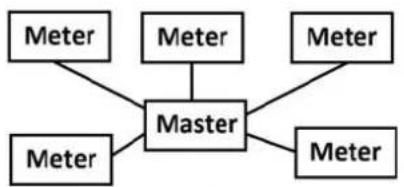
It is recommended to use non-shielded twisted pair cable with wire area of 0.8 mm ^2 , for example two-wire standard telephone cable JYStY N*2*0.8 mm ^2 . If shielded cable is used the shield must not be connected to any of the two bus wires. Maximum total length of the bus is 1000 m. Maximum length between a slave and a repeater is 350 m.
10.2 Protocol Description
General
The communication protocol described in this chapter meets the requirements of EN 13757-2 and EN 13757-3.
The communication can be divided in two parts. One part is reading data from the meter and the other part is sending data to it.
The data readout procedure starts when the master sends a REQ_UD2 telegram to the meter. The meter responds with a RSP_UD telegram. A typical readout is a multi-telegram readout.
Some data in the meter can only be read by first sending a SND_UD followed by REQ_UD2. This is true for load profiles, demand, log files and normally for harmonics.
Using SND_UD telegrams data can be sent to the meter.
Communication objects
The following quantities can be read by sending a REQ_UD2 to the meter
| Register Communication objects | |
| Active import energy, total Total cumulative active imported energy | |
| Active import energy, tariff 1 Cumulative active imported energy tariff 1 | |
| Active import energy, tariff 2 Cumulative active imported energy tariff 2 | |
| Active import energy, tariff 3 Cumulative active imported energy tariff 3 | |
| Active import energy, tariff 4 Cumulative active imported energy tariff 4 | |
| Reactive import energy, total Total cumulative reactive imported energy | |
| Reactive import energy, tariff 1 Cumulative reactive imported energy tariff 1 | |
| Reactive import energy, tariff 2 Cumulative reactive imported energy tariff 2 | |
| Reactive import energy, tariff 3 Cumulative reactive imported energy tariff 3 | |
| Reactive import energy, tariff 4 Cumulative reactive imported energy tariff 4 | |
| Active export energy, total Total cumulative active exported energy | |
| Active export energy, tariff 1 Cumulative active exported energy tariff 1 | |
| Active export energy, tariff 2 Cumulative active exported energy tariff 2 | |
| Active export energy, tariff 3 Cumulative active exported energy tariff 3 | |
| Active export energy, tariff 4 Cumulative active exported energy tariff 4 | |
| Reactive export energy, total Total cumulative reactive exported energy | |
| Reactive export energy, tariff 1 Cumulative reactive exported energy tariff 1 | |
| Reactive export energy, tariff 2 Cumulative reactive exported energy tariff 2 | |
| Reactive export energy, tariff 3 Cumulative reactive exported energy tariff 3 | |
| Reactive export energy, tariff 4 Cumulative reactive exported energy tariff 4 | |
| CT Ratio primary current Current transformer ratio primary current | |
| CT Ratio secondary current Current transformer ratio secondary current | |
| VT Ratio primary voltage Voltage transformer ratio primary voltage | |
| VT Ratio secondary voltage Voltage transformer ratio secondary voltage | |
| Outputs Read and set status of outputs | |
| Register | Communication objects |
| Inputs, current state Read current state of input 1,2,3 and 4 | |
| Inputs, stored state Read and reset stored state of input 1,2,3 and 4 | |
| Inputs, counter Read and clear input pulse counter 1,2,3 and 4 | |
| Current N Instantaneous current in the neutral wire | |
| Current, L1 Instantaneous current in the L1 phase | |
| Current, L2 Instantaneous current in the L2 phase | |
| Current, L3 Instantaneous current in the L3 phase | |
| Voltage, L1-N Instantaneous voltage between L1 and neutral | |
| Voltage, L2-N Instantaneous voltage between L2 and neutral | |
| Voltage, L3-N Instantaneous voltage between L3 and neutral | |
| Voltage, L1-L2 Instantaneous voltage between L1 and L2 | |
| Voltage, L2-L3 Instantaneous voltage between L2 and L3 | |
| Voltage, L1-L3 Instantaneous voltage between L1 and L3 | |
| Active Power, Total Instantaneous total active power | |
| Active Power, L1 Instantaneous active power in L1 | |
| Active Power, L2 Instantaneous active power in L2 | |
| Active Power, L3 Instantaneous active power in L3 | |
| Active energy net Total Total cumulative active net energy | |
| Active energy net L1 Cumulative active net energy in L1 | |
| Active energy net L2 Cumulative active net energy in L2 | |
| Active energy net L3 Cumulative active net energy in L3 | |
| Power factor tot. Instantaneous total power factor | |
| Power factor L1 Instantaneous power factor in L1 | |
| Power factor L2 Instantaneous power factor in L2 | |
| Power factor L3 Instantaneous power factor in L3 | |
| Active energy currency conversion factor | Price in currency per kWh |
| Active import energy, total in Currency | Total cumulative active imported energy expressed in currency |
| Active energy CO2 conversion factor | CO2 emission in kg per kWh |
| Active import energy, total in CO2 Total cumulative active imported energy expressed in CO2 | |
| Reactive Power, Total Instantaneous total reactive power | |
| Reactive Power, L1 | Instantaneous reactive power in L1 |
| Reactive Power, L2 | Instantaneous reactive power in L2 |
| Reactive Power, L3 | Instantaneous reactive power in L3 |
| Reactive energy net Tot. | Total cumulative reactive net energy |
| Reactive energy net L1 | Cumulative reactive net energy in L1 |
| Reactive energy net L2 | Cumulative reactive net energy in L2 |
| Reactive energy net L3 | Cumulative reactive net energy in L3 |
| Apparent Power, Total | Instantaneous total apparent power |
| Apparent Power, L1 Instantaneous | apparent power in L1 |
| Apparent Power, L2 Instantaneous | apparent power in L2 |
| Apparent Power, L3 Instantaneous | apparent power in L3 |
| Apparent energy net Tot. Total cum | ulative apparent net energy |
| Apparent energy net L1 Cumulative | apparent net energy in L1 |
| Apparent energy net L2 Cumulative | apparent net energy in L2 |
| Apparent energy net L3 Cumulative | apparent net energy in L3 |
| Voltage phase angle, L1 Instantane | ous voltage phase angle for L1 (L1 volt-age is reference) |
| Voltage phase angle, L2 Instantane | ous voltage phase angle for L2 (L1 volt-age is reference) |
| Voltage phase angle, L3 Instantane | ous voltage phase angle for L3 (L1 volt-age is reference) |
| Current phase angle, L1 Instantane | ous current phase angle for L1 (L1 volt-age is reference) |
| Current phase angle, L2 Instantane | ous current phase angle for L2 (L1 volt-age is reference) |
| Current phase angle, L3 Instantane | ous current phase angle for L3 (L1 volt-age is reference) |
| Phase angle power, Total Instantane | ous phase angle for total power |
| Phase angle power L1 Instantaneous | us phase angle power for L1 |
| Phase angle power L2 Instantaneous | us phase angle power for L2 |
| Phase angle power L3 Instantaneous | us phase angle power for L3 |
| Installation check Read result of and clear installation check | |
| Current quadrant, Total Quadrant in which the meter is measuring | |
| Current quadrant, L1 Quadrant in which the meter is measuring, L1 | |
| Current quadrant, L2 Quadrant in which the meter is measuring, L2 | |
| Current quadrant, L3 Quadrant in which the meter is measuring, L3 | |
| Power fail counter Read and reset power fail counter | |
| Total power outage time Read and reset total power outage time | |
| Current tariff Read and set current tariff | |
| Manufacturer Manufacturer information | |
| FW-version Firmware version | |
| Frequency Instantaneous mains frequency | |
| Warning flags | Read warning flags |
| Info flags | Read info flags |
| Alarm flags | Read alarm flags |
| Error flags | Read error flags |
| Date and time | Read and set date and time |
| Previous values | Read previous values |
| Load profile | Read load profile data |
| Demand | Read Demand (max. and min. data) |
| Event log | Read event log data |
| Register Communication objects | |
| System log Read system log data | |
| Net quality log Read net quality log | data |
| Current harmonics Read THD and | harmonics on each current measured |
| Voltage harmonics Read THD and | harmonics on each voltage measured |
| Apparent import energy, total Total | cumulative apparent imported energy |
| Apparent export energy, total Total | cumulative apparent exported energy |
| Active import energy, L1 Cumulative | active imported energy in the L1 phase |
| Active import energy, L2 Cumulative | active imported energy in the L2 phase |
| Active import energy, L3 Cumulative | active imported energy in the L3 phase |
| Active export energy, L1 Cumulative | active exported energy in the L1 phase |
| Active export energy, L2 Cumulative | active exported energy in the L2 phase |
| Active export energy, L3 Cumulative | active exported energy in the L3 phase |
| Reactive import energy, L1 Cumulative | active reactive imported energy in the L1 phase |
| Reactive import energy, L2 Cumulative | active reactive imported energy in the L2 phase |
| Reactive import energy, L3 Cumulative | active reactive imported energy in the L3 phase |
| Reactive export energy, L1 Cumulative | active reactive exported energy in the L1 phase |
| Reactive export energy, L2 Cumulative | active reactive exported energy in the L2 phase |
| Reactive export energy, L3 Cumulative | active reactive exported energy in the L3 phase |
| Apparent import energy, L1 Cumulative | active apparent imported energy in the L1 phase |
| Apparent import energy, L2 Cumulative | active apparent imported energy in the L2 phase |
| Apparent import energy, L3 Cumulative | active apparent imported energy in the L3 phase |
| Apparent export energy, L1 Cumulative | active apparent exported energy in the L1 phase |
| Apparent export energy, L2 Cumulative | active apparent exported energy in the L2 phase |
| Apparent export energy, L3 Cumulative | active apparent exported energy in the L3 phase |
| Resettable active energy imp. Tot. | Active imported energy accumulated since last reset |
| Resettable active energy exp. Tot. | Active exported energy accumulated since last reset |
| Resettable reactive energy imp. Tot. | Reactive imported energy accumulated since last reset |
| Resettable reactive energy exp. Tot. | Reactive exported energy accumulated since last reset |
| Reset counter for Resettable active energy imp. Tot. | Number of resets done for resettable active im-ported energy |
| Reset counter for Resettable active energy exp. Tot. | Number of resets done for resettable active ex-ported energy |
| Reset counter for Resettable reac-tive energy imp. Tot. | Number of resets done for resettable reactive im-ported energy |
| Reset counter for Resettable reac-tive energy exp. Tot. | Number of resets done for resettable reactive ex-ported energy |
| Pulse outputs, pulse frequency | Pulse frequency for pulse outputs with unit 1-4 |
| Number of elements | Number of elements: 1 for single phase, 2 for 3-phase without neutral, 3 for 3-phase with neutral |
| Type designation | In ASCII, for example “A43 513-100” |
| Current state for Daylight Savings Time (DST), Day of week, Daytype and Season | Compound variable containing current state of Day-light Savings Time (DST), Day of week, Daytype and Season |
Read/write commands
The following tasks are possible to perform with SND_UD telegrams:
| Command |
| Set tariff |
| Set primary address |
| Change baud rate |
| Reset power fail counter |
| Reset power outage time |
| Set CT Ratio primary current |
| Set CT Ratio secondary current |
| Set VT Ratio primary voltage |
| Set VT Ratio secondary voltage |
| Select Status information |
| Reset stored state input |
| Reset input counters |
| Set output |
| Set date time |
| Set date |
| Send Password |
| Freeze Max demand |
| Set communication access level |
| Read Request Load profile |
| Read request previous values |
| Read request demand (maximum and minimum) |
| Read request Log (System, Event, and Net quality Logs) |
| Read request current harmonics |
| Read request voltage harmonics |
10.2.1 Telegram Format
General
M-Bus uses 3 different telegram formats. The formats are identified by the start character.
| Single Character Short Frame Long Frame | ||
| E5H Start (10h) Start (68h) | ||
| C-Field L-Field | ||
| A-Field L-Field | ||
| Check Sum Start (68h) | ||
| Stop (16h) C-Field | ||
| A-Field | ||
| CI-Field | ||
| User Data (0-252 Bytes) | ||
| Check Sum | ||
| Stop (16h | ||
The Single Character format consists of a single character and is used to acknowledge received telegrams.
The Short Frame format is identified by its start character (10h) and consists of five characters. Besides the C- and A-fields it includes the check sum and the stop character 16h.
The Long Frame format is identified by its start character (68h) and consists of a variable number of characters. After the start character the L-field is transmitted twice, then the start character once again followed by the C-, A- and CI-fields. The user data (0 - 252 bytes) is transmitted after the CI-field followed by the check sum and the stop character (16h).
10.2.1.1 Field description
General
All fields in the telegram have a length of 1byte (8 bits).
The L-Field
The L-Field (length field) gives the size of the user data (in bytes) plus 3 (for the C-, A- and CI-Fields). It is transmitted twice in the telegrams using the long frame format.
The C-Field
The C-Field (control field) contains information about the direction of the data flow and error handling. Besides labeling the functions and the actions caused by them, the control field specifies the direction of data flow and is responsible for various parts of the communication to and from the meter.
The following table shows the coding of the C-Field:
| Bit No. 7 6 5 4 3 2 1 0 | ||||||||
| To meter 0 PRM FCB | FCV F3 | F2 F1 | F0 | |||||
| From meter 0 PRM 0 0 F3 F2 | F1 | F0 |
The primary message bit (PRM) is used to specify the direction of the data flow. It is set to 1 when a telegram is sent from a master to the meter and to 0 in the other direction.
The frame count bit valid (FCV) is set to 1 by the master to indicate that the frame count bit (FCB) is used. When the FCV is set to 0, the meter ignores the FCB.
The FCB is used to indicate successful transmission procedures. A master shall toggle the bit after a successful reception of a reply from the meter. If the expected reply is missing, or the reception of it is faulty, the master resends the same telegram with the same FCB. The meter answers, to a REQ_UD2-request with toggled FCB and a set FCV, with a RSP_UD containing the next telegram of a multi-telegram answer. If the FCB is not toggled it will repeat the last telegram. The actual values will be updated in a repeated telegram.
On receipt of a SND_NKE the meter clears the FCB. The meter uses the same FCB for primary addressing, secondary addressing and point-to-point communication.
The bits 0 to 3 (F0, F1, F2 and F3) of the control field are the function code of the message. The following table shows the function codes:
| Comand C-Field (binary) | C-Field (hex) | Telegram Description | |
| SND_NKE | 0100 0000 | 40 | Short frame Initialization of meter |
| SND_UD | 01F1 0011 | 53/73 | Long frame Send user data to meter |
| REQ_UD2 | 01F1 1011 | 5b | Short frame Request for class 2 data |
| RSP_UD | 0000 1000 | 08 | Long frame Data transfer form meter to master after request. |
A-Field
The A-Field (address field) is used to address the recipient in the calling direction, and to identify the sender of information in the receiving direction. The size of this field is one byte, and can therefore take values from 0 to 255.
The following table shows the allocation of addresses:
| Address Description | |
| 0 Factory default | |
| 1-250 Can be given to meters as individual primary addresses, either via the bus (secondary addressing) or via the buttons directly on the meter. | |
| 251-252 Reserved for future use. | |
| 253 Used by the secondary addressing procedure (FDh). | |
| 254 Used for point-to-point communication (FEh). The meter replies with its primary address. | |
| 255 | Used for broadcast transmissions to all meters (FFh). None of the meters replies to a broadcast message. |
CI-Field
The CI-field (control information) codes the type and sequence of application data to be transmitted in the frame. Bit two (counting begins with bit 0, value 4), called M-bit or Mode bit, in the CI-field gives information about the used byte sequence in multi-byte data structures. For communication with the meter, the Mode bit shall not be set (Mode 1) meaning the least significant byte of a multi-byte record is transmitted first.
The following table shows the codes to be used by the master:
| CI_Field codes Application | |
| 51h Data send | |
| 52h Selection of slaves | |
| B8h Set baud rate to 300 | |
| B9h Set baud rate to 600 | |
| Bah Set baud rate to 1200 | |
| BBh Set baud rate to 2400 | |
| BCh Set baud rate to 4800 | |
| BDh Set baud rate to 9600 | |
| BEh Set baud rate to 19200 | |
| BFh Set baud rate to 38400 | |
The meter uses code 72 in the CI-Field to respond to requests for user data.
User data
The User Data contains the data to be sent to the recipient.
The following table shows the structure of the data sent from the meter to the master:
| Fixed data header Data | records MDH | |
| 12 bytes Variable number | of bytes 1 byte |
The following table shows the structure of the data sent from the master to the meter:
| Data records |
| Variable number of bytes |
Fixed data header
The following table shows the structure of the fixed data header:
| ID No. | Manufacturer | Version | Medium | Access | No. Status | Signature | |
| 4 bytes | 2 bytes | 1 byte | 1 byte | 1 byte | 1 byte | 2 byte |
The following list explains the content of the fixed data header:
- Identification No. is the 8-digit serial number of the meter (BCD coded).
- Manufacturer is set to 0442h meaning ABB
- Version specifies the version of the protocol implementation. The meters currently use the protocol version equal to 0x20.
- Medium byte is set to 02h to indicate electricity.
- Access number is a counter that counts successful accesses.
• Status byte is used to indicate the meter status.
| Bit | Meaning |
| 0 | Meter busy |
| 1 | Internal error |
| 2 | Power low |
| 3 | Permanent error |
| 4 | Temporary error |
| 5 | Installation error |
| 6 | Not used |
| 7 | Not used |
• Signature is set to 00 00h
Data records
The data, together with information regarding coding, length and the type of data is transmitted in data records. The maximum total length of the data records is 240 bytes.
The following table shows the structure of the data record (transmitted left to right):
| Data Record Header Data | ||||
| Data Information Block (DIB) Value Information Block (VIB) | ||||
| DIF DIFE VIF VIFE | ||||
| 1 byte 0-10 bytes | 1 byte 0-10 bytes | 0-n bytes | ||
Each Data record consists of a data record header (DRH) and the actual data. The DRH in turn consists of the data information block (DIB) to describe the length, type and coding of the data, and the value information block (VIB) to give the value of the unit and the multiplier.
Data information block (DIB)
The DIB contains at least one byte (Data Information Field, DIF), and is in some cases expanded with, a maximum of 10, DIFE's (Data Information Field Extension).
The following table shows the structure of the Data Information Field (DIF):
| Bit 7 | Bit 6 | Bit 5 | Bit 4 | Bit 3 | Bit 2 | Bit 1 | Bit 0 |
| Extension bit | LSB ^1 of storage No. | Function Field | Data Field | ||||
- Least significant bit.
The following list explains the content of the DIF:
- The Extension Bit is set when the next byte is a DIFE.
- The LSB of storage No. is normally set to 0 to indicate actual value. (1=stored value).
- The Function Field is set to 00 for instantaneous values, 01 for maximum values and 10 for minimum values.
- The Data Field shows the format of the data. The following table shows the coding of the data field:
| Code | Meaning | Length |
| 0000 | No Data | 0 |
| 0001 | 8 Bit Integer | 1 |
| 0010 | 16 Bit Integer | 2 |
| 0100 | 32 Bit Integer | 4 |
| 0111 | 64 Bit Integer | 8 |
| 1010 | 4 digit BCD | 2 |
| 1011 | 6 digit BCD | 3 |
| 1100 | 8 digit BCD | 4 |
| 1101 Variable Length | (ASCII) | Variable |
| 1110 12 digit BCD 6 |
The following table shows the structure of the Data Information Field Extension (DIFE)
| Bit 7 Bit 6 Bit 5 Bit | 4 Bit 3 Bit 2 Bit 1 Bit 0 | ||||||
| Extension bit Unit | Tariff | Storage No. | |||||
The following list explains the content of the DIFE:
- Unit is used for power and energy values show the type of power/energy. It is also used to define the number of inputs/outputs and to specify sign of offset when accessing event log data.
- Tariff is used for energy values to give tariff information.
- Storage number is set to 0 in values read to indicate momentary values. Storage number bigger than 0 is used to indicate previously stored values, i.e., values stored at a specific point of time in the past.
Value Information block (VIB)
VIB follows a DIF or DIFE without extension bit. It contains one value information field (VIF) and is in some cases expanded with up to 10 value information field extensions (VIFE).
The following table shows the structure of the value information field (VIF):
| Bit 7 | 6 | 5 | 4 | 3 | 2 | 1 | 0 |
| Extension Bit | Value Information | ||||||
Value information contains information about the value (unit, status, etc.,) The extension bit is set when the next byte is a VIFE.
If VIF or VIFE = FFh the next VIFE is manufacturer specific. The manufacturer specific VIFE has the same construction as a VIF. If the extension bit of the manufacturer specific VIFE is set, and the VIFE is less than 1111 1000, the next byte is a standard VIFE, otherwise it is the first data byte. If the extension bit of the manufacturer specific VIFE is set and the VIFE is bigger than or equal to 1111 1000, the next byte is an extension of manufacturer specific VIFE's.
Data
The Data follows a VIF or a VIFE without the extension bit set.
Manufacturer data header (MDH)
The manufacturer data header (MDH) is either made up by the character 1Fh that indicates that more data will follow in the next telegram, or by 0Fh indicating the last telegram.
Check sum
The Check Sum is used to recognize transmission and synchronization faults. It is calculated from the arithmetical sum, of the bytes from the control field to the last user data, without taking carry digits into account.
10.2.2 Value Information Field codes
10.2.2.1 Standard VIF codes
| VIF-code Description Range coding Range | |||
| E000 0nnn Energy 10( | ^nnn-3) Wh 0.00 | 1Wh to 10000Wh | |
| E010 1nnn Power 10( | ^nnn-3) W 0.00 | 1W to 10000W | |
| E010 00nn Duration nn = 00 seconds | nn = 01 minutesnn = 10 hoursnn = 11 days | ||
| E110 110n Time point n = 0: date | n = 1: time & date | Data type GData type F or 6 byte BCD coding | |
| E111 1000 Fabrication No. 00000000 to | 99999999 | ||
| E111 1010 Bus address | 0-250 | ||
| 1111 1011 | Extension of VIF-codes | Not used by the meter | |
| 1111 1101 | Extension of VIF-codes | True VIF is given in the first VIFE and is coded using Table FD | |
| 1111 1111 | Manufacturer specific | Next VIFE is manufacturer specific | |
10.2.2.2 Standard codes for VIFE used with extension indicator FDh
If the VIF contains the extension indicator FDh the true VIF is contained in the first VIFE.
| VIFE-code | Description |
| E000 1010 Manufacturer | |
| E000 1100 Version | |
| E000 1110 Firmware Version | |
| E001 1010 Digital Output (binary) | |
| E001 1011 Digital Input (binary) | |
| E001 1100 Baud rate | |
| E010 01nn | Interval length, 00: seconds, 01: minutes), 10: hours, 11: days |
| VIFE-code Description | |
| E100 nnnn 10( | nnnn-9) Volts |
| E101 nnnn 10( | nnnn-12) A |
| E110 0001 Cumulating counter | |
| E001 0110 Password | |
10.2.2.3 Standard codes for VIFE
The following values for VIFE's are defined for an enhancement of VIF's other than FDh and FBh:
| VIFE-code Description | |
| E010 0111 Per measurement (interval) | ^12 |
| E011 1001 Start date(/time) of | |
| E110 1f1b Date (/time) of, b = 0: end of, b = 1: begin of, f is not used in meters, always 0^12 | |
| 1111 1111 Next VIFE is manufacturer specific | |
- Date (/time) of “or duration of” relates to the information which the whole data record contains.
- The information about usage of data type F (date and time) or data type G (date) can be derived from the data field (0010b: type G/0100: type F).
10.2.2.4 First manufacturer specific VIFE-codes
| VIFE-code Description | |
| E000 0000 Total | |
| E000 0001 L1 | |
| E000 0010 L2 | |
| E000 0011 L3 | |
| E000 0100 N | |
| E000 0101 L1-L2 | |
| E000 0110 L3-L2 | |
| E000 0111 L1-L3 | |
| E001 0000 Pulse frequency | |
| E001 0011 Tariff | |
| E001 0100 Installation check | |
| E001 0101 Status of values | |
| E001 0111 Current quadrant | |
| E001 1000 Power fail counter | |
| E010 0000 Current Transformer (CT) ratio primary current | |
| E010 0001 Voltage Transformer (VT) ratio primary voltage | |
| E010 0010 Current Transformer (CT) ratio secondary current | |
| E010 0011 Voltage Transformer (VT) ratio secondary voltage | |
| E010 0100 CO2 conversion factor (kg * 10 -3/kWh) | |
| E010 0101 Currency conversion factor (curr * 10 -3/kWh) | |
| E010 0110 Error flags | |
| E010 0111 Warning flags | |
| E010 1000 Information flags | |
| E010 1001 Alarm flags | |
| E010 1010 Type designation (e.g. A43 552-100) | |
| E010 1011 Sub interval | |
| E010 1101 Number of elements | |
| E100 0nnn Phase angle voltage (degrees *10 (nnn-3)) | |
| E100 1nnn Phase angle current (degrees *10 (nnn-3)) | |
| E101 0nnn Phase angle power (degrees *10 (nnn-3)) | |
| E101 1nnn Frequency (Hz *10 (nnn-3)) | |
| E110 0nnn Power factor (*10 (nnn-3)) | |
| E110 1010 Change communication write access level | |
| E110 1100 Power outage time | |
| E110 1101 Current harmonics | |
| E110 1110 Voltage harmonics | |
| E110 1111 Event type | |
| E111 0000 Measurement period | |
| E111 0001 Reset counter for energy | |
| E111 0010 Resettable register | |
| E111 1000 Extension of manufacturer specific VIFE's, next VIFE(s) used for numbering | |
| E111 1001 Extension of manufacturer specific VIFE's, next VIFE(s) specifies actual meaning | |
| E111 1110 Extension of manufacturer specific VIFE's, next VIFE(s) used for manufacturer specific record errors/status | |
10.2.2.5 VIFE-Codes for reports of record errors (meter to master)
VIFE-code Type of record error Error group
E000 0000 None
E001 0101 No data available (undefined value)
E001 1000 Data error Data errors
10.2.2.6 VIFE-Codes for object actions (master to meter)
VIFE-code Action Description
E000 0111 Clear Set data to zero
E000 1011 Freeze data Freeze data to storage
number
10.2.2.7 2:nd manufacturer specific VIFE followed after VIFE 1111 1000 (F8 hex):
VIFE-code Description
Ennn nnnn Used for numbering (0-127)
10.2.2.8 2:nd manufacturer specific VIFE followed after VIFE 1111 1001 (F9 hex):
VIFE-code Description
E000 0010 Quantity specification of maximum demand
E000 0011 Quantity specification of previous values
E000 0100 Quantity specification of load profile
E000 0110 Tariff source
E000 1010 DST, day of week, day type, season
E000 1011 Telegram set
E001 0000 Readout request of active imported energy load profile in format energy register values at end of intervals
E001 0010 Readout request of reactive imported energy load profile in format energy register values at end of intervals
E001 0100 Readout request of input 1 counter load profile in format counter register values at end of intervals
E001 0110 Readout request of input 2 counter load profile in format counter register values at end of intervals
E001 1000 Readout request of maximum demand
E001 1001 Readout request of previous values
E001 1011 Readout request of current harmonics
E001 1100 Readout request of active exported energy load profile in format energy register values at end of intervals
| VIFE-code Description | |
| E001 1110 Readout request of reactive exported energy load profile in format energy register values at end of intervals | |
| E010 0000 Readout request of apparent imported energy load profile in format energy register values at end of intervals | |
| E010 0010 Readout request of apparent exported energy load profile in format energy register values at end of intervals | |
| E010 0100 Readout request of input 3 counter load profile in format counter register values at end of intervals | |
| E010 0110 Readout request of input 4 counter load profile in format counter register values at end of intervals | |
| E010 1000 Readout request of current load profile | |
| E010 1001 Readout request of voltage load profile | |
| E010 1010 Readout request of THD voltage load profile | |
| E010 1011 Readout request of THD current load profile | |
| E010 1100 Readout request of power factor load profile | |
| E010 1101 Readout request of voltage harmonics | |
| E010 1110 System log | |
| E011 0000 Net quality log | |
| E011 0010 Event log | |
| E011 0011 Event type system log | |
| E011 0101 Event type net quality log | |
| E011 0111 Event type event log | |
| E011 1000 Readout request of load profile based on channel number | |
| E100 0nnn Energy in CO | _2(kg *10^nnn-7) |
| E100 1nnn Energy in currency (currency * 10 nnn-3) | |
| E101 snnn Level nnn (binary coding), s=1 for sliding, 0 for non-sliding | |
10.2.2.9 2:nd manufacturer specific VIFE followed after VIFE 1111 1110 (FE hex):
| VIFE-code Description |
| E00t opsl Data status for load profile, t=time change, o = overflow, p = power outage during interval, s = short interval, l = long interval |
10.2.3 Communication process
General
The Data Link Layer uses two kinds of transmission services:
Send/Confirm SND/CON
Request/Respond REQ/RSP
When the meter has received a correct telegram it waits between 35 and 80 ms before it responds. A telegram is considered as correct if it passes the following tests:
- Start /Parity /Stop bits per character
- Start /Check Sum /Stop characters per telegram format
- In case of a long frame, the number of additional characters received match the L-field (= L Field +6) .
- If the received data is reasonable
The time between a response from the meter and a new message from the master must be at least 20 ms.
Send/confirm procedure
SND_NKE is used to initiate communication with the meter. When the meter has received an NKE followed by a REQ_UD2 (see description below), the 1st telegram from the meter is sent out.
If the meter was selected for secondary addressing it will be deselected. The value of the FCB is cleared in the meter, i.e., the meter expects that the first telegram from a master with FCV=1 contains an FCB=1.
The meter can either confirm a correct reception with the single character acknowledge E5h), or it can omit confirmation because it did not receive the telegram correctly.
SND_UD is used to send data to the meter. The meter either confirms reception of a correct message or it omits confirmation because it did not receive the telegram correctly.
Request/respond procedure
REQ_UD2 is used by the master to request data from the meter. RSP_UD is used by the meter to transfer data to the master. The meter indicates to the master that more data will follow in the next telegram by sending 1Fh as the last user data.
If the meter does not respond to the REQ_UD2, it's an indication that the message was not received correctly or that the address does not match.
10.2.3.1 Selection and secondary addressing
General
It is possible to communicate with the meter using secondary addressing. The secondary addressing takes place with the help of a selection:
| 68h | 0Bh | 0Bh | 68h | 53h | FDh | 52h | ID | 1-4 | Manu-facturer 1-2 | Generation^1 | Med-dium | CS | 16h |
- Generation means the same thing as version.
The master sends a SND_UD with the control information 52h to the address 253 (FDh) and fills the specific meter secondary address fields (identification number, manufacturer, version and medium) with the values of the meter that is to be addressed. The address (FDh) and the control information (52h) is the indication for the meter to compare the following secondary address with its own, and to change into the selected state should it match. In this case the meter answers the selection with an acknowledgement (E5h), otherwise it does not reply. Selected state means that the meter can be addressed with the bus address 253 (FDh).
Wild cards
During selection individual positions of the secondary addresses can be occupied by wildcards. Such a wildcard means that this position will not be taken into account during selection. In the identification number each individual digit can be wild-carded by a wildcard nibble Fh while the fields for manufacturer, version and medium can be wild-carded by a wildcard byte FFh. The meter will remain selected until it receives a selection command with non-matching secondary addresses, a selection command with CI=56h, or a SND_NKE to address 253.
10.3 Standard Readout of Meter Data
General
This section describes the readout of the default telegrams containing energy and instrumentation values etc. The data readout procedure starts when the master sends a REQ_UD2 telegram to the meter. The meter responds with a RSP_UD telegram. A typical readout is a multi-telegram readout. The last DIF in the user data part of the telegram is 1F to indicate that there is more data in the next telegram, or 0F if there are no more telegrams.
For EQ meters there are up to 7 default telegrams to read. In meters with internal clock more telegrams may follow, containing previous values data. The most recent values are sent out first having storage number 1, then the second most recently stored values with storage number 2 and so on until all stored previous values have been read. If no previous values exist in a meter with internal clock a telegram is sent out where all data is marked with status byte for "No data available".
It is also possible to read previous values starting from a specific date and backwards in time by sending a special read request.

Note - Note: Normally the meter is configured to send out power values as 32 bit integers, expressed in W (or var/VA) with 2 decimals. This means that the maximum power possible to express is approximately ± 21 MW
Below following sections is an example of a readout of the 7 default telegrams and 2 previous values telegrams, containing the most recent snapshot of previous values. Note that these are examples only, data types and scaling of the quantities can differ between meters, as well as the allocation of quantities to different telegrams.
10.3.1 Example of the 1st telegram (all values are hexadecimal)
| Byte No. | Size Value | Description | |
| 1 1 68 Start | character | ||
| 2 1 FA L-field, calculated from C field to last user data | |||
| 3 1 FA L-field, repeated | |||
| 4 1 68 Start | character | ||
| 5 1 08 C-field, RSP_UD | |||
| 6 1 xx A-field, address | |||
| 7 1 72 CI-field, variable data respond, LSB first | |||
| 8-11 4 xxxxxxxx Identification Number, 8 BCD digits | |||
| 12-13 2 4204 | Manufacturer: ABB | ||
| 14 | 1 02 Version | ||
| 15 | 1 02 Medium, 02 = Electricity | ||
| 16 | 1 xx Number of accesses | ||
| 17 | 1 xx Status | ||
| 18-19 2 0000 | Signature (0000 = no encryption) | ||
| 20 1 0E DIF | size, 12 | digit BCD | |
| 21 1 84 VIF | for units | kWh with resolution | 0,01kWh |
| 22 1 xx VIFE | status | ||
| 23-28 6 xxxxxxxxxxxxx | Active imported energy, Total | ||
| 29 1 8E DIF | size, 12 | digit BCD | |
| 30 1 10 DIFE, tariff 1 | |||
| 31 1 84 VIF | for units | kWh with resolution | 0,01kWh |
| 32 1 xx VIFE | status | ||
| 33-38 6 xxxxxxxxxxxxx | Active imported energy, Tariff 1 | ||
| 39 1 8E DIF | size, 12 | digit BCD | |
| 40 1 20 DIFE, tariff 2 | |||
| 41 1 84 VIF | for units | kWh with resolution | 0,01kWh |
| 42 1 xx VIFE | status | ||
| 43-48 6 xxxxxxxxxxxxx | Active imported energy, Tariff 2 | ||
| 49 1 8E DIF | size, 12 | digit BCD | |
| 50 1 30 DIFE, tariff 3 | |||
| 51 1 84 VIF | for units | kWh with resolution | 0,01kWh |
| 52 1 xx VIFE | status | ||
| 53-58 6 xxxxxxxxxxxxx | Active imported energy, Tariff 3 | ||
| 59 1 8E DIF | size, 12 | digit BCD | |
| 60 1 80 DIFE, | |||
| 61 1 10 DIFE, tariff 4 | |||
| 62 1 84 VIF | for units | kWh with resolution | 0,01kWh |
| 63 1 xx VIFE | status | ||
| 64-69 6 xxxxxxxxxxxxx | Active imported energy, Tariff 4 | ||
| 70 1 8E DIF | size, 12 | digit BCD | |
| 71 1 40 DIFE, unit 1 | |||
| 72 1 84 VIF | for units | kWh with resolution | 0,01kWh |
| 73 1 xx VIFE | status | ||
| 74-79 6 xxxxxxxxxxxxx | Active exported energy, Total | ||
| 80 1 8E DIF | size, 12 | digit BCD | |
| 81 1 50 DIFE, tariff 1, unit 1 | |||
| 82 1 84 VIF | for units | kWh with resolution | 0,01kWh |
| 83 1 xx VIFE | status | ||
| 84-89 6 xxxxxxxxxxxxx | Active exported energy, Tariff 1 | ||
| 90 1 8E DIF | size, 12 | digit BCD | |
| 91 1 60 DIFE, tariff 2, unit 1 | |||
| 92 1 84 VIF | for units | kWh with resolution | 0,01kWh |
| 93 1 xx VIFE | status | ||
| 94-99 6 xxxxxxxxxxxxx | Active exported energy, Tariff 2 | ||
| 100 1 8E DIF | size, 12 | digit BCD | |
| 101 1 70 DIFE, tariff | 3, unit 1 | ||
| 102 1 84 VIF for units kWh with resolution | 0,01kWh | ||
| 103 1 xx VIFE status | |||
| 104-109 6 xxxxxxxxxx | Active exported energy, Tariff 3 | ||
| 110 1 8E DIF size, 12 digit BCD | |||
| 111 1 C0 DIFE, unit | 1 | ||
| 112 1 10 DIFE, tariff | 4 | ||
| 113 1 84 VIF for units kWh with resolution | 0,01kWh | ||
| 114 1 xx VIFE status | |||
| 115-120 6 xxxxxxxxxx | Active exported energy, Tariff 4 | ||
| 121 1 01 DIF size, 8 bit integer | |||
| 122 1 FF VIF next byte is manufacturer specific | |||
| 123 1 93 VIFE current tariff | |||
| 124 1 xx VIFE status | |||
| 125 1 xx Current tariff | |||
| 126 1 04 DIF size, 32 bit integer | |||
| 127 1 FF VIF next byte is manufacturer specific | |||
| 128 1 A0 VIFE CT ratio primary current | |||
| 129 1 xx VIFE status | |||
| 130-133 4 xxxxxxxx | Current transformer ratio primary current | ||
| 134 1 04 DIF size, 32 bit integer | |||
| 135 1 FF VIF next byte is manufacturer specific | |||
| 136 1 A1 VIFE VT ratio primary voltage | |||
| 137 1 xx VIFE status | |||
| 138-141 4 xxxxxxxx | Voltage transformer ratio primary voltage | ||
| 142 1 04 DIF size, 32 bit integer | |||
| 143 1 FF VIF next byte is manufacturer specific | |||
| 144 1 A2 VIFE CT ratio secondary current | |||
| 145 1 xx VIFE status | |||
| 146-149 4 xxxxxxxx | Current transformer ratio secondary current | ||
| 150 1 04 DIF size, 32 bit integer | |||
| 151 1 FF VIF next byte is manufacturer specific | |||
| 152 1 A3 VIFE VT ratio secondary voltage | |||
| 153 1 xx VIFE status | |||
| 154-157 4 xxxxxxxx | Voltage transformer ratio secondary voltage | ||
| 158 1 07 DIF size, 64 bit integer | |||
| 159 1 FF VIF next byte is manufacturer specific | |||
| 160 1 A6 VIFE error flags (binary) | |||
| 161 1 xx VIFE status | |||
| 162-169 8 xxxxxxxxxxxxxxxxx 64 Error flags | |||
| 170 1 07 DIF size, 64 bit integer | |||
| Byte No. | Size | Value | Description |
| 171 1 FF VIF next byte is manufacturer specific | |||
| 172 1 A7 VIFE warning flags (binary) | |||
| 173 1 xx VIFE status | |||
| 174-181 8xxxxxxxxxxxxxx 64 Warning flags | |||
| 182 1 07 DIF size, 64 bit integer | |||
| 183 1 FF VIF next byte is manufacturer specific | |||
| 184 1 A8 VIFE information flags (binary) | |||
| 185 1 xx VIFE status | |||
| 186-193 8xxxxxxxxxxxxxx 64 Information flags | |||
| 194 1 07 DIF size, 64 bit integer | |||
| 195 1 FF VIF next byte is manufacturer specific | |||
| 196 1 A9 VIFE alarm flags (binary) | |||
| 197 1 xx VIFE status | |||
| 198-205 8xxxxxxxxxxxxxxxxxx 64 Alarm flags | |||
| 206 1 0E DIF size, 12 digit BCD | |||
| 207 1 ED VIF time/date | |||
| 208 1 xx VIFE status | |||
| 209-214 6xxxxxxxxxxx Time and date (sec,min,hour,day,month,year) | |||
| 215 1 02 DIF size, 16 bit integer | |||
| 216 1 FF VIF next byte is manufacturer specific | |||
| 217 1 F9 VIF extension of manufacturer specific VIFE's, next VIFE specifies actual meaning | |||
| 218 1 8A VIFE DST, day of week, day type, season | |||
| 219 1 xx VIFE status | |||
| 220-221 2 xxx DST data in bit 0: 1:DST active, 0:DST inactive Day of week data in bit 4-6: 001-111; Monday-Sunday Active day type in bit 8-11: 0000-1111; Type of day 1-16 Season data in bit 12-13: 00-11; Season 1-4 | |||
| 222 1 0D DIF size, variable length, ASCII coding | |||
| 223 1 FD VIF extension of VIF-codes | |||
| 224 1 8E VIFE Firmware | |||
| 225 1 xx VIFE status | |||
| 226 1 0C Byte specifying length of following ASCII string, see below | |||
| 227-238 12xxxxxxxxxxxxxxxxxxxxxx Firmware version (ASCII coded, LSB byte first), containing of a character followed by three or four numbers (0-255) separated by periods, for example A1.13.0. Length can be 6-16 bytes | |||
| 239 1 0D DIF size, variable length, ASCII coding | |||
| 240 1 FF VIF next byte is manufacturer specific | |||
| 241 1 AA VIFE Type designation | |||
| 242 1 xx VIFE status | |||
| 243 1 0B Byte specifying length | |||
| Byte No. | Size Value | Description | |
| 244-254 11 | xxxxxxxxxxxxxx | xxxxxxxxxxxxxx | Type designation (ASCII coded, LSB byte first), for example: A44 552-100 |
| 255 1 1F DIF, more | records will follow in next telegram | ||
| 255 1 xx CS checksum, calculated from C field to last data | |||
| 256 1 16 Stop character | |||
10.3.2 Example of 2nd telegram (all values are hexadecimal)
| Byte No. | Size Value | Description | |
| 1 1 68 Start | character | ||
| 2 1 FC L-field, calculated from C field to last user data | |||
| 3 1 FC L-field, repeated | |||
| 4 1 68 Start | character | ||
| 5 1 08 C-field, RSP_UD | |||
| 6 1 xx A-field, address | |||
| 7 1 72 CI-field, variable data respond, LSB first | |||
| 8-11 4 xxxxxxx Identification Number, 8 BCD digits | |||
| 12-13 2 4204 | Manufacturer: ABB | ||
| 14 | 1 02 Version | ||
| 15 | 1 02 Medium, 02 = Electricity | ||
| 16 | 1 xx Number of accesses | ||
| 17 | 1 xx Status | ||
| 18-19 2 0000 | Signature (0000 = no encryption) | ||
| 20 | 1 04 DIF size, 32 bit integer | ||
| 21 | 1 FF | VIF next byte is manufacturer specific | |
| 22 | 1 98 VIFE Power fail counter | ||
| 23 | 1 xx VIFE status | ||
| 24-27 | 4 xxxxxxxxx Power fail counter | ||
| 28 | 1 04 DIF size, 32 bit integer | ||
| 29 | 1 A9 | VIF for units W with resolution 0,01W | |
| 30 | 1 xx VIFE status | ||
| 31-34 | 4 xxxxxxxxx Active power, Total | ||
| 35 | 1 04 DIF size, 32 bit integer | ||
| 36 | 1 A9 | VIF for units W with resolution 0,01W | |
| 37 | 1 FF | VIFE next byte is manufacturer specific | |
| 38 | 1 81 VIFE L1 | ||
| 39 | 1 xx VIFE status | ||
| 40-43 | 4 xxxxxxxxx Active power, L1 | ||
| 44 | 1 04 DIF size, 32 bit integer | ||
| 45 | 1 A9 | VIF for units W with resolution 0,01W | |
| 46 | 1 FF | VIFE next byte is manufacturer specific | |
| 47 | 1 82 VIFE L2 | ||
| 48 1 xx VIFE status | |||
| 49-52 4 xxxxxxxx Active power, L2 | |||
| 53 1 04 DIF size, 32 bit integer | |||
| 54 1 A9 VIF for units W with resolution 0,01W | |||
| 55 1 FF VIFE next byte is manufacturer specific | |||
| 56 1 83 VIFE L3 | |||
| 57 1 xx VIFE status | |||
| 58-61 4 xxxxxxxxx Active power, L3 | |||
| 62 1 84 DIF size, 32 bit integer | |||
| 63 1 80 DIFE (Unit = 0) | |||
| 64 1 40 DIFE (Unit = 1, => xx10 (2)) | |||
| 65 1 A9 VIF for units var with resolution 0,01var | |||
| 66 1 xx VIFE status | |||
| 67-70 4 xxxxxxxxx Reactive power, Total | |||
| 71 1 84 DIF size, 32 bit integer | |||
| 72 1 80 DIFE (Unit = 0) | |||
| 73 1 40 DIFE (Unit = 1, => xx10 (2)) | |||
| 74 1 A9 VIF for units var with resolution 0,01var | |||
| 75 1 FF VIFE next byte is manufacturer specific | |||
| 76 1 81 VIFE L1 | |||
| 77 1 xx VIFE status | |||
| 78-81 4 xxxxxxxx Reactive power, L1 | |||
| 82 1 84 DIF size, 32 bit integer | |||
| 83 1 80 DIFE (Unit = 0) | |||
| 84 1 40 DIFE (Unit = 1, => xx10 (2)) | |||
| 85 1 A9 VIF for units var with resolution 0,01var | |||
| 86 1 FF VIFE next byte is manufacturer specific | |||
| 87 1 82 VIFE L2 | |||
| 88 1 xx VIFE status | |||
| 89-92 4 xxxxxxxx Reactive power, L2 | |||
| 93 1 84 DIF size, 32 bit integer | |||
| 94 1 80 DIFE (Unit = 0) | |||
| 95 1 40 DIFE (Unit = 1, => xx10 (2)) | |||
| 96 1 A9 VIF for units var with resolution 0,01var | |||
| 97 1 FF VIFE next byte is manufacturer specific | |||
| 98 1 83 VIFE L3 | |||
| 99 1 xx VIFE status | |||
| 100-103 4 xxxxxxxx Reactive power, L3 | |||
| 104 1 84 DIF size, 32 bit integer | |||
| 105 1 80 DIFE (Unit = 0) | |||
| 106 1 80 DIFE (Unit = 0) | |||
| 107 1 40 DIFE (Unit = 1, => x100 (4)) | |||
| 108 1 A9 VIF for units VA with resolution 0,01VA | |||
| 109 1 xx VIFE status | |||
| 110-113 4 xxxxxxxx Apparent power, Total | |||
| 114 1 84 DIF size, 32 bit integer | |||
| 115 1 80 DIFE (Unit = 0) | |||
| 116 1 80 DIFE (Unit = 0) | |||
| 117 1 40 DIFE (Unit = 1, => x100 (4)) | |||
| 118 1 A9 VIF for units VA with resolution 0,01VA | |||
| 119 1 FF VIFE next byte is manufacturer specific | |||
| 120 1 81 VIFE L1 | |||
| 121 1 xx VIFE status | |||
| 122-125 4 xxxxxxxx Apparent power, L1 | |||
| 126 1 84 DIF size, 32 bit integer | |||
| 127 1 80 DIFE (Unit = 0) | |||
| 128 1 80 DIFE (Unit = 0) | |||
| 129 1 40 DIFE (Unit = 1, => x100 (4)) | |||
| 130 1 A9 VIF for units VA with resolution 0,01VA | |||
| 131 1 FF VIFE next byte is manufacturer specific | |||
| 132 1 82 VIFE L2 | |||
| 133 1 xx VIFE status | |||
| 134-137 4 xxxxxxxx Apparent power, L2 | |||
| 138 1 84 DIF size, 32 bit integer | |||
| 139 1 80 DIFE (Unit = 0) | |||
| 140 1 80 DIFE (Unit = 0) | |||
| 141 1 40 DIFE (Unit = 1, => x100 (4)) | |||
| 142 1 A9 VIF for units VA with resolution 0,01VA | |||
| 143 1 FF VIFE next byte is manufacturer specific | |||
| 144 1 83 VIFE L3 | |||
| 145 1 xx VIFE status | |||
| 146-149 4 xxxxxxxx Apparent power, L3 | |||
| 150 1 04 DIF size, 32 bit integer | |||
| 151 1 FD VIF extension of VIF-codes | |||
| 152 1 C8 VIFE for units V with resolution 0,1V | |||
| 153 1 FF VIFE next byte is manufacturer specific | |||
| 154 1 81 VIFE L1 | |||
| 155 1 xx VIFE status | |||
| 156-159 4 xxxxxxxx Voltage L1 - N | |||
| 160 1 04 DIF size, 32 bit integer | |||
| 161 1 FD VIF extension of VIF-codes | |||
| 162 1 C8 VIFE for units V with resolution 0,1V | |||
| 163 | 1 FF VIFE next | byte is manufacturer | specific |
| 164 | 1 82 VIFE L2 | ||
| 165 | 1 xx VIFE status | ||
| 166-169 | 4 xxxxxxxx | Voltage L2 - N | |
| 170 | 1 04 DIF size, 3 | 2 bit integer | |
| 171 | 1 FD VIF extension of VIF-codes | ||
| 172 | 1 C8 VIFE for units V with resolution | 0,1V | |
| 173 | 1 FF VIFE next | byte is manufacturer | specific |
| 174 | 1 83 VIFE L3 | ||
| 175 | 1 xx VIFE status | ||
| 176-179 | 4 xxxxxxxx | Voltage L3 - N | |
| 180 | 1 04 DIF size, 3 | 2 bit integer | |
| 181 | 1 FD VIF extension of VIF-codes | ||
| 182 | 1 C8 VIFE for units V with resolution | 0,1V | |
| 183 | 1 FF VIFE next | byte is manufacturer | specific |
| 184 | 1 85 VIFE L1 - L2 | ||
| 185 | 1 xx VIFE status | ||
| 186-189 | 4 xxxxxxxx | Voltage L1 - L2 | |
| 190 | 1 04 DIF size, 3 | 2 bit integer | |
| 191 | 1 FD VIF extension of VIF-codes | ||
| 192 | 1 C8 VIFE for units V with resolution | 0,1V | |
| 193 | 1 FF VIFE next | byte is manufacturer | specific |
| 194 | 1 86 VIFE L2 - L3 | ||
| 195 | 1 xx VIFE status | ||
| 196-199 | 4 xxxxxxxx | Voltage L3 - L2 | |
| 200 | 1 04 DIF size, 3 | 2 bit integer | |
| 201 | 1 FD VIF extension of VIF-codes | ||
| 202 | 1 C8 VIFE for units V with resolution | 0,1V | |
| 203 | 1 FF VIFE next | byte is manufacturer | specific |
| 204 | 1 87 VIFE L1 - L3 | ||
| 205 | 1 xx VIFE status | ||
| 206-209 | 4 xxxxxxxx | Voltage L1 - L3 | |
| 210 | 1 04 DIF size, 3 | 2 bit integer | |
| 211 | 1 FD VIF extension of VIF-codes | ||
| 212 | 1 DA VIFE for units A with resolution | 0,01A | |
| 213 | 1 FF VIFE next | byte is manufacturer | specific |
| 214 | 1 81 VIFE L1 | ||
| 215 | 1 xx VIFE status | ||
| 216-219 | 4 xxxxxxxx | Current L1 | |
| 220 | 1 04 DIF size, 3 | 2 bit integer | |
| 221 | 1 FD VIF extension of VIF-codes | ||
| Byte No. | Size | Value | Description |
| 222 1 | DA V | FE for u | units A with resolution 0,01A |
| 223 1 | FF V | FE next | byte is manufacturer specific |
| 224 1 | 82 V | FE L2 | |
| 225 1 | xx V | FE status | |
| 226-229 4 | xxxxxxx | Current L2 | |
| 230 1 | 04 DIF size, 3 | 2 bit integer | |
| 231 1 | FD V | F extension of VIF-codes | |
| 232 1 | DA V | FE for u | units A with resolution 0,01A |
| 233 1 | FF V | FE next | byte is manufacturer specific |
| 234 1 | 83 V | FE L3 | |
| 235 1 | xx V | FE status | |
| 236-239 4 | xxxxxxx | Current L3 | |
| 240 1 | 04 DIF size, 3 | 2 bit integer | |
| 241 1 | FD V | F extension of VIF-codes | |
| 242 1 | DA V | FE for u | units A with resolution 0,01A |
| 243 1 | FF V | FE next | byte is manufacturer specific |
| 244 1 | 84 V | FE N | |
| 245 1 | xx V | FE status | |
| 246-249 4 | xxxxxxx | Current N | |
| 250 1 | 0A DIF size, 4 | digit BCD | |
| 251 1 | FF V | F next byte is manufacturer specific | |
| 252 1 | E9 V | FE Frequency with resolution 0.01Hz | |
| 253 1 | xx V | FE status | |
| 254-255 2 | xxxx Frequency | ||
| 256 1 | 1F DIF more records will follow in next telegram | ||
| 257 1 | xx CS checksum, calculated from C field to last data | ||
| 258 1 | 16 Stop character | ||
10.3.3 Example of 3rd telegram (all values are hexadecimal)
| Byte No. | Size | Value | Description |
| 1 | 1 68 Start character | ||
| 2 | 1 F4 L-field, calculated from | C field to last user data | |
| 3 | 1 F4 L-field, repeated | ||
| 4 | 1 68 Start character | ||
| 5 | 1 08 C-field, RSP_UD | ||
| 6 | 1 xx A-field, address | ||
| 7 | 1 72 CI-field, variable data respond, LSB first | ||
| 8-11 | 4 xxxxxxxx Identification Number, 8 BCD digits | ||
| 12-13 2 4204 | Manufacturer: ABB | ||
| 14 | 1 02 Version | ||
| 15 | 1 02 Medium, 02 = Electricity | ||
| Byte No. | Size Value | Description | |
| 16 1 xx Number of accesses | |||
| 17 1 xx Status | |||
| 18-19 2 0000 Signature (0000 = no encryption) | |||
| 20 1 0E DIF size, 12 digit BCD | |||
| 21 1 FF VIF next byte is manufacturer specific | |||
| 22 1 EC VIFE Power outage time | |||
| 23 1 xx VIFE status | |||
| 24-29 6 xxxxxxxxxxxxx Power outage time (sec, min, hour, days, LSB first) | |||
| 30 1 02 DIF size, 16 bit integer | |||
| 31 1 FF VIF next byte is manufacturer specific | |||
| 32 1 E0 VIFE power factor with resolution 0,001 | |||
| 33 1 xx VIFE status | |||
| 34-35 2 xxx Power factor, Total | |||
| 36 1 02 DIF size, 16 bit integer | |||
| 37 1 FF VIF next byte is manufacturer specific | |||
| 38 1 E0 VIFE power factor with resolution 0,001 | |||
| 39 1 FF VIFE next byte is manufacturer specific | |||
| 40 1 81 VIFE L1 | |||
| 41 1 xx VIFE status | |||
| 42-43 2 xxx Power factor, L1 | |||
| 44 1 02 DIF size, 16 bit integer | |||
| 45 1 FF VIF next byte is manufacturer specific | |||
| 46 1 E0 VIFE power factor with resolution 0,001 | |||
| 47 1 FF VIFE next byte is manufacturer specific | |||
| 48 1 82 VIFE L2 | |||
| 49 1 xx VIFE status | |||
| 50-51 2 xxx Power factor, L2 | |||
| 52 1 02 DIF size, 16 bit integer | |||
| 53 1 FF VIF next byte is manufacturer specific | |||
| 54 1 E0 VIFE power factor with resolution 0,001 | |||
| 55 1 FF VIFE next byte is manufacturer specific | |||
| 56 1 83 VIFE L3 | |||
| 57 1 xx VIFE status | |||
| 58-59 2 xxx Power factor, L3 | |||
| 60 1 02 DIF size, 16 bit integer | |||
| 61 1 FF VIF next byte is manufacturer specific | |||
| 62 1 D2 VIFE phase angle power with resolution 0.1 | |||
| 63 1 xx VIFE status | |||
| 64-65 2 xxx Phase angle power, Total | |||
| 66 1 02 DIF size, 16 bit integer | |||
| 67 1 FF VIF next byte is manufacturer specific | |||
| 68 1 D2 VIFE phase angle power with resolution 0.1 | |||
| 69 1 FF VIFE next byte is manufacturer specific | |||
| 70 1 81 VIFE L1 | |||
| 71 1 xx VIFE status | |||
| 72-73 2 xxxx Phase angle power, L1 | |||
| 74 1 02 DIF size, 16 bit integer | |||
| 75 1 FF VIF next byte is manufacturer specific | |||
| 76 1 D2 VIFE phase angle power with resolution 0.1 | |||
| 77 1 FF VIFE next byte is manufacturer specific | |||
| 78 1 82 VIFE L2 | |||
| 79 1 xx VIFE status | |||
| 80-81 2 xxxx Phase angle power, L2 | |||
| 82 1 02 DIF size, 16 bit integer | |||
| 83 1 FF VIF next byte is manufacturer specific | |||
| 84 1 D2 VIFE phase angle power with resolution 0.1 | |||
| 85 1 FF VIFE next byte is manufacturer specific | |||
| 86 1 83 VIFE L3 | |||
| 87 1 xx VIFE status | |||
| 88-89 2 xxxx Phase angle power, L3 | |||
| 90 1 02 DIF size, 16 bit integer | |||
| 91 1 FF VIF next byte is manufacturer specific | |||
| 92 1 C2 VIFE phase angle voltage with resolution 0.1 | |||
| 93 1 FF VIFE next byte is manufacturer specific | |||
| 94 1 81 VIFE L1 | |||
| 95 1 xx VIFE status | |||
| 96-97 2 xxxx Phase angle voltage, L1 | |||
| 98 1 02 DIF size, 16 bit integer | |||
| 99 1 FF VIF next byte is manufacturer specific | |||
| 100 1 C2 VIFE phase angle voltage with resolution 0.1 | |||
| 101 1 FF VIFE next byte is manufacturer specific | |||
| 102 1 82 VIFE L2 | |||
| 103 1 xx VIFE status | |||
| 104-105 2 xxxx Phase angle voltage, L2 | |||
| 106 1 02 DIF size, 16 bit integer | |||
| 107 1 FF VIF next byte is manufacturer specific | |||
| 108 1 C2 VIFE phase angle voltage with resolution 0.1 | |||
| 109 1 FF VIFE next byte is manufacturer specific | |||
| 110 1 83 VIFE L3 | |||
| 111 1 xx VIFE status | |||
| 112-113 2 xxxx Phase angle voltage, L3 | |||
| 114 1 02 DIF size, 16 bit integer | |||
| 115 | 1 FF VIF next byte is manufacturer specific | ||
| 116 | 1 CA VIFE phase angle current with resolution 0.1 | ||
| 117 | 1 FA VIFE next byte is manufacturer specific | ||
| 118 | 1 81 VIFE L1 | ||
| 119 | 1 xx VIFE status | ||
| 120-121 | 2 xxxx Phase angle current, L1 | ||
| 122 | 1 02 DIF size, 16 bit integer | ||
| 123 | 1 FF VIF next byte is manufacturer specific | ||
| 124 | 1 CA VIFE phase angle current with resolution 0.1 | ||
| 125 | 1 FF VIFE next byte is manufacturer specific | ||
| 126 | 1 82 VIFE L2 | ||
| 127 | 1 xx VIFE status | ||
| 128-129 | 2 xxxx Phase angle current, L2 | ||
| 130 | 1 02 DIF size, 16 bit integer | ||
| 131 | 1 FF VIF next byte is manufacturer specific | ||
| 132 | 1 CA VIFE phase angle current with resolution 0.1 | ||
| 133 | 1 FF VIFE next byte is manufacturer specific | ||
| 134 | 1 83 VIFE L3 | ||
| 135 | 1 xx VIFE status | ||
| 136-137 | 2 xxxx Phase angle current, L3 | ||
| 138 | 1 8E DIF size, 12 digit BCD | ||
| 139 | 1 80 DIFE, | ||
| 140 | 1 40 DIFE, unit 2 | ||
| 141 | 1 84 VIF for units kvarh with resolution 0,01kvarh | ||
| 142 | 1 xx VIFE status | ||
| 143-148 | 6 xxxxxxxxxxxxxx Reactive imported energy, Total | ||
| 149 | 1 8E DIF size, 12 digit BCD | ||
| 150 | 1 90 DIFE, tariff 1 | ||
| 151 | 1 40 DIFE, unit 2 | ||
| 152 | 1 84 VIF for units kvarh with resolution 0,01kvarh | ||
| 153 | 1 xx VIFE status | ||
| 154-159 | 6 xxxxxxxxxxxxxx Reactive imported energy, Tariff 1 | ||
| 160 | 1 8E DIF size, 12 digit BCD | ||
| 161 | 1 A0 DIFE, tariff 2 | ||
| 162 | 1 40 DIFE, unit 2 | ||
| 163 | 1 84 VIF for units kvarh with resolution 0,01kvarh | ||
| 164 | 1 xx VIFE status | ||
| 165-170 | 6 xxxxxxxxxxxxxx Reactive imported energy, Tariff 2 | ||
| 171 | 1 8E DIF size, 12 digit BCD | ||
| 172 | 1 B0 DIFE, tariff 3 | ||
| 173 | 1 40 DIFE, unit 2 | ||
| 174 | 1 84 VIF for units kvarh with resolution 0,01kvarh | ||
| 175 | 1 xx VIFE status | ||
| 176-181 | 6 xxxxxxxxxx | Reactive imported energy, Tariff 3 | |
| 182 | 1 8E DIF size, 12 digit BCD | ||
| 183 | 1 80 DIFE, | ||
| 184 | 1 50 DIFE, tariff 4, unit 2 | ||
| 185 | 1 84 VIF for units kvarh with resolution 0,01kvarh | ||
| 186 | 1 xx VIFE status | ||
| 187-192 | 6 xxxxxxxxxx | Reactive imported energy, Tariff 4 | |
| 193 | 1 8E DIF size, 12 digit BCD | ||
| 194 | 1 C0 DIFE, unit bit 0 | ||
| 195 | 1 40 DIFE, unit bit 1, unit bit0-1-> unit 3 | ||
| 196 | 1 84 VIF for units kvarh with resolution 0,01kvarh | ||
| 197 | 1 xx VIFE status | ||
| 198-203 | 6 xxxxxxxxxx | Reactive exported energy, Total | |
| 204 | 1 8E DIF size, 12 digit BCD | ||
| 205 | 1 D0 DIFE, tariff 1, unit bit 0 | ||
| 206 | 1 40 DIFE, unit bit 1, unit bit 0-1-> unit 3 | ||
| 207 | 1 84 VIF for units kvarh with resolution 0,01kvarh | ||
| 208 | 1 xx VIFE status | ||
| 209-214 | 6 xxxxxxxxxx | Reactive exported energy, Tariff 1 | |
| 215 | 1 8E DIF size, 12 digit BCD | ||
| 216 | 1 E0 DIFE, tariff 2, unit bit 0 | ||
| 217 | 1 40 DIFE, unit bit 1, unit bit 0-1-> unit 3 | ||
| 218 | 1 84 VIF for units kvarh with resolution 0,01kvarh | ||
| 219 | 1 xx VIFE status | ||
| 220-225 | 6 xxxxxxxxxx | Reactive exported energy, Tariff 2 | |
| 226 | 1 8E DIF size, 12 digit BCD | ||
| 227 | 1 F0 DIFE, tariff 3, unit bit 0 | ||
| 228 | 1 40 DIFE, unit bit 1, unit bit 0-1-> unit 3 | ||
| 229 | 1 84 VIF for units kvarh with resolution 0,01kvarh | ||
| 230 | 1 xx VIFE status | ||
| 231-236 | 6 xxxxxxxxxx | Reactive exported energy, Tariff 3 | |
| 237 | 1 8E DIF size, 12 digit BCD | ||
| 238 | 1 C0 DIFE, unit bit 0 | ||
| 239 | 1 50 DIFE, tariff 4, unit bit 1, unit bit 0-1-> unit 3 | ||
| 240 | 1 84 VIF for units kvarh with resolution 0,01kvarh | ||
| 241 | 1 xx VIFE status | ||
| 242-247 | 6 xxxxxxxxxx | Reactive exported energy, Tariff 4 | |
| 248 | 1 01 DIF size, 8 bit integer | ||
| 249 | 1 FF VIF next byte is manufacturer specific | ||
| 250 1 AD VIFE number of elements | |||
| 251 1 xx VIFE status | |||
| 252 1 xx Number of elements | |||
| 253 1 1F DIF, more records will follow in next telegram | |||
| 254 1 xx CS checksum, calculated from C field to last data | |||
| 255 1 16 Stop character | |||
10.3.4 Example of the 4th telegram (all values are hexadecimal)
| Byte No. | Size Value | Description | |
| 1 1 68 Start | character | ||
| 2 1 AE L-field, calculated from C field to last user data | |||
| 3 1 AE L-field, repeated | |||
| 4 1 68 Start | character | ||
| 5 1 08 C-field, RSP_UD | |||
| 6 1 xx A-field, address | |||
| 7 1 72 CI-field, variable data respond, LSB first | |||
| 8-11 4 xxxxxxx Identification Number, 8 BCD digits | |||
| 12-13 2 420 | 4 Manufacturer: ABB | ||
| 14 | 1 02 Version | ||
| 15 | 1 02 Medium, 02 = Electricity | ||
| 16 | 1 xx Number of accesses | ||
| 17 | 1 xx Status | ||
| 18-19 2 000 | 0 Signature (0000 = no encryption) | ||
| 20 | 1 01 DIF size, 8 bit integer | ||
| 21 | 1 FF | VIF next byte is manufacturer specific | |
| 22 | 1 97 VIFE current quadrant | ||
| 23 | 1 xx VIFE status | ||
| 24 | 1 xx Current quadrant, total | ||
| 25 | 1 01 DIF size, 8 bit integer | ||
| 26 | 1 FF | VIF next byte is manufacturer specific | |
| 27 | 1 97 VIFE current quadrant | ||
| 28 | 1 FF | VIF next byte is manufacturer specific | |
| 29 | 1 81 VIFE L1 | ||
| 30 | 1 xx VIFE status | ||
| 31 | 1 xx Current quadrant, L1 | ||
| 32 | 1 01 DIF size, 8 bit integer | ||
| 33 | 1 FF | VIF next byte is manufacturer specific | |
| 34 | 1 97 VIFE current quadrant | ||
| 35 | 1 FF | VIF next byte is manufacturer specific | |
| 36 | 1 82 VIFE L2 | ||
| 37 | 1 xx VIFE status | ||
| 38 1 xx | Current quad | drant, L2 | |
| 39 1 01 | DIF size, 8 bit integer | ||
| 40 1 FF | VIF next byte is manufacturer specific | ||
| 41 1 97 | VIFE current quadrant | ||
| 42 1 FF | VIF next byte is manufacturer specific | ||
| 43 1 83 | VIFE L3 | ||
| 44 1 xx | VIFE status | ||
| 45 1 xx | Current quad | drant, L3 | |
| 46 1 81 | DIF size, 8 bit integer | ||
| 47 1 40 | DIFE (Unit = 1) | ||
| 48 1 FD | VIF extension of VIF-codes | ||
| 49 1 9A | VIFE digital output | ||
| 50 1 xx | VIFE status | ||
| 51 1 xx | Output 1, current state | ||
| 52 1 81 | DIF size, 8 bit integer | ||
| 53 1 80 | DIFE, | ||
| 54 1 40 | DIFE (Unit = 2) | ||
| 55 1 FD | VIF extension of VIF-codes | ||
| 56 1 9A | VIFE digital output | ||
| 57 1 xx | VIFE status | ||
| 58 1 xx | Output 2, current state | ||
| 59 1 81 | DIF size, 8 bit integer | ||
| 60 1 C0 | DIFE (Unit = 1) | ||
| 61 1 40 | DIFE (Unit = 2) | ||
| 62 1 FD | VIF extension of VIF-codes | ||
| 63 1 9A | VIFE digital output | ||
| 64 1 xx | VIFE status | ||
| 65 1 xx | Output 3, current state | ||
| 66 1 81 | DIF size, 8 bit integer | ||
| 67 1 80 | DIFE, | ||
| 68 1 80 | DIFE, | ||
| 69 1 40 | DIFE (Unit = 4) | ||
| 70 1 FD | VIF extension of VIF-codes | ||
| 71 1 9A | VIFE digital output | ||
| 72 1 xx | VIFE status | ||
| 73 1 xx | Output 4, current state | ||
| 74 1 81 | DIF size, 8 bit integer | ||
| 75 1 40 | DIFE (Unit = 1) | ||
| 76 1 FD | VIF extension of VIF-codes | ||
| 77 1 9B | VIFE digital input | ||
| 78 1 xx | VIFE status | ||
| 79 1 xx Input 1 current state | |||
| 80 1 81 DIF size, 8 bit integer | |||
| 81 1 80 DIFE, | |||
| 82 1 40 DIFE (Unit = 2) | |||
| 83 1 FD VIF extension of VIF-codes | |||
| 84 1 9B VIFE digital input | |||
| 85 1 xx VIFE status | |||
| 86 1 xx Input 2 current state | |||
| 87 1 81 DIF size, 8 bit integer | |||
| 88 1 C0 DIFE (Unit = 1) | |||
| 89 1 40 DIFE (Unit = 2) | |||
| 90 1 FD VIF extension of VIF-codes | |||
| 91 1 9B VIFE digital input | |||
| 92 1 xx VIFE status | |||
| 93 1 xx Input 3 current state | |||
| 94 1 81 DIF size, 8 bit integer | |||
| 95 1 80 DIFE, | |||
| 96 1 80 DIFE, | |||
| 97 1 40 DIFE (Unit = 4) | |||
| 98 1 FD VIF extension of VIF-codes | |||
| 99 1 9B VIFE digital input | |||
| 100 1 xx VIFE status | |||
| 101 1 xx Input 4 current state | |||
| 102 1 C1 DIF size, 8 bit integer, storage number 1 | |||
| 103 1 40 DIFE (Unit = 1) | |||
| 104 1 FD VIF extension of VIF-codes | |||
| 105 1 9B VIFE digital input | |||
| 106 1 xx VIFE status | |||
| 107 1 xx Input 1, stored state (1 if current state has been 1) | |||
| 108 1 C1 DIF size, 8 bit integer, storage number 1 | |||
| 109 1 80 DIFE, | |||
| 110 1 40 DIFE (Unit = 2) | |||
| 111 1 FD VIF extension of VIF-codes | |||
| 112 1 9B VIFE digital input | |||
| 113 1 xx VIFE status | |||
| 114 1 xx Input 2, stored state (1 if current state has been 1) | |||
| 115 1 C1 DIF size, 8 bit integer, storage number 1 | |||
| 116 1 C0 DIFE (Unit = 1) | |||
| 117 1 40 DIFE (Unit = 2) | |||
| 118 1 FD VIF extension of VIF-codes | |||
| 119 1 9B VIFE digital input | |||
| 120 | 1 xx VIFE status | ||
| 121 | 1 xx Input 3, stored state (1 if current) | state has been 1) | |
| 122 | 1 C1 DIF size, 8 bit integer, storage number 1 | ||
| 123 | 1 80 DIFE, | ||
| 124 | 1 80 DIFE, | ||
| 125 | 1 40 DIFE (Unit = 4) | ||
| 126 | 1 FD VIF extension of VIF-codes | ||
| 127 | 1 9B VIFE digital input | ||
| 128 | 1 xx VIFE status | ||
| 129 | 1 xx Input 4, stored state (1 if current) | state has been 1) | |
| 130 | 1 8E DIF size, 12 digit BCD | ||
| 131 | 1 40 DIFE (Unit = 1) | ||
| 132 | 1 FD VIF extension of VIF-codes | ||
| 133 | 1 E1 VIFE cumulating counter | ||
| 134 | 1 xx VIFE status | ||
| 135-140 | 6 xxxxxxxxxxxxxx Counter 1 (input 1) | ||
| 141 | 1 8E DIF size, 12 digit BCD | ||
| 142 | 1 80 DIFE, | ||
| 143 | 1 40 DIFE (Unit = 2) | ||
| 144 | 1 FD VIF extension of VIF-codes | ||
| 145 | 1 E1 VIFE cumulating counter | ||
| 146 | 1 xx VIFE status | ||
| 147-152 | 6 xxxxxxxxxxxxxx Counter 2 (input 2) | ||
| 153 | 1 8E DIF size, 12 digit BCD | ||
| 154 | 1 C0 DIFE (Unit = 1) | ||
| 155 | 1 40 DIFE (Unit = 2) | ||
| 156 | 1 FD VIF extension of VIF-codes | ||
| 157 | 1 E1 VIFE cumulating counter | ||
| 158 | 1 xx VIFE status | ||
| 159-164 | 6 xxxxxxxxxxxxxx Counter 3 (input 3) | ||
| 165 | 1 8E DIF size, 12 digit BCD | ||
| 166 | 1 80 DIFE, | ||
| 167 | 1 80 DIFE, | ||
| 168 | 1 40 DIFE (Unit = 4) | ||
| 169 | 1 FD VIF extension of VIF-codes | ||
| 170 | 1 E1 VIFE cumulating counter | ||
| 171 | 1 xx VIFE status | ||
| 172-177 | 6 xxxxxxxxxxxxxx Counter 4 (input 4) | ||
| 178 | 1 1F DIF, more records will follow in next telegram | ||
| 179 | 1 xx CS checksum, calculated from C field to last data | ||
| 180 | 1 16 Stop character | ||
10.3.5 Example of the 5th telegram (all values are hexadecimal)
| Byte No. | Size Value | Description | |
| 1 1 68 Start | character | ||
| 2 1 A4 L-field, calculated from C field to last user data | |||
| 3 1 A4 L-field, repeated | |||
| 4 1 68 Start | character | ||
| 5 1 08 C-field, RSP_UD | |||
| 6 1 xx A-field, address | |||
| 7 1 72 CI-field, variable data respond, LSB first | |||
| 8-11 4 xxxxxxxx Identification Number, 8 BCD digits | |||
| 12-13 2 4204 Manufacturer: ABB | |||
| 14 1 02 Version | |||
| 15 1 02 Medium, 02 = Electricity | |||
| 16 1 xx Number of accesses | |||
| 17 1 xx Status | |||
| 18-19 2 0000 Signature (0000 = no encryption) | |||
| 20 1 0E DIF size, 12 digit BCD | |||
| 21 1 84 VIF for units kWh with resolution 0,01kWh | |||
| 22 1 FF VIFE next byte is manufacturer specific | |||
| 23 1 F2 VIFE resettable energy | |||
| 24 1 xx VIFE status | |||
| 25-30 6 xxxxxxxxxxx Resettable active imported energy, Total | |||
| 31 1 8E DIF size, 12 digit BCD | |||
| 32 1 40 DIFE (Unit = 1) | |||
| 33 1 84 VIF for units kWh with resolution 0,01kWh | |||
| 34 1 FF VIFE next byte is manufacturer specific | |||
| 35 1 F2 VIFE resettable energy | |||
| 36 1 xx VIFE status | |||
| 37-42 | 6 xxxxxxxxxxx Resettable active exported energy, Total | ||
| 43 1 8E DIF size, 12 digit BCD | |||
| 44 1 80 DIFE | |||
| 45 1 40 DIFE (Unit = 2) | |||
| 46 1 84 VIF for units kvarh with resolution 0,01kvarh | |||
| 47 1 FF VIFE next byte is manufacturer specific | |||
| 48 1 F2 VIFE resettable energy | |||
| 49 1 xx VIFE status | |||
| 50-55 | 6 xxxxxxxxxxx Resettable reactive imported energy, Total | ||
| 56 1 8E DIF size, 12 digit BCD | |||
| 57 1 C0 | DIFE (Unit = 1) | ||
| 58 1 40 DIFE (Unit = 2) | |||
| 59 1 84 VIF for units kvar with resolution 0,01kvarh | |||
| 60 1 FF VIFE next byte is manufacturer specific | |||
| 61 1 F2 VIFE resettable energy | |||
| 62 1 xx VIFE status | |||
| 63-68 6 xxxxxxxxxxxxx | xx Resettable reactive | exported energy, Total | |
| 69 1 04 DIF size, 32 bit integer | |||
| 70 1 FF VIFE next byte is manufacturer specific | |||
| 71 1 F1 VIFE reset counter | |||
| 72 1 xx VIFE status | |||
| 73-76 4 xxxxxxxx Reset counter for active imported energy, Total | |||
| 77 1 84 DIF size, 32 bit integer | |||
| 78 1 40 DIFE (Unit = 1) | |||
| 79 1 FF VIFE next byte is manufacturer specific | |||
| 80 1 F1 VIFE reset counter | |||
| 81 1 xx VIFE status | |||
| 82-85 4 xxxxxxxx Reset counter for active exported energy, Total | |||
| 86 1 84 DIF size, 32 bit integer | |||
| 87 1 80 DIFE | |||
| 88 1 40 DIFE (Unit = 2) | |||
| 89 1 FF VIFE next byte is manufacturer specific | |||
| 90 1 F1 VIFE reset counter | |||
| 91 1 xx VIFE status | |||
| 92-95 4 xxxxxxxx Reset counter for reactive imported energy, Total | |||
| 96 1 84 DIF size, 32 bit integer | |||
| 97 1 C0 DIFE (Unit = 1) | |||
| 98 1 40 DIFE (Unit = 2) | |||
| 99 1 FF VIFE next byte is manufacturer specific | |||
| 100 1 F1 VIFE reset counter | |||
| 101 1 xx VIFE status | |||
| 102-105 4 xxxxxxxx | Reset counter for reactive exported energy, Total | ||
| 106 1 0E DIF size, 12 digit BCD | |||
| 107 1 FF VIFE next byte is manufacturer specific | |||
| 108 1 F9 VIF extension of manufacturer specific VIFE's | |||
| 109 1 C4 Energy in CO2 with resolution 0,001 kg | |||
| 110 1 xx VIFE status | |||
| 111-116 6 xxxxxxxx | xx CO2 for active imported energy, Total | ||
| 117 1 0E DIF size, 12 digit BCD | |||
| 118 1 FF VIFE next byte is manufacturer specific | |||
| 119 1 F9 VIF extension of manufacturer specific VIFE's | |||
| 120 1 C9 Energy in Currency with resolution 0,01 currency | |||
| 121 1 xx VIFE status | |||
| 122-127 6 xxxxxxxx | xx Currency for active imported energy, Total | ||
| 128 1 04 DIF size, 32 bit integer | |||
| 129 1 FF VIFE next | byte is manufacturer | specific | |
| 130 1 A4 CO2 conversion factor in g/kWh | |||
| 131 1 xx VIFE status | |||
| 132-133 4 xxxxxxxx | CO2 conversion factor for active energy | ||
| 134 1 04 DIF size, 3 | 2 bit integer | ||
| 135 1 FF VIFE next | byte is manufacturer | specific | |
| 136 1 A5 Currency conversion factor in 0 | 001 currency/kWh | ||
| 137 1 xx VIFE status | |||
| 138-143 4 xxxxxxxx | Currency conversion factor for active energy | ||
| 144 1 8E DIF size, 12 digit BCD | |||
| 145 1 80 DIFE | |||
| 146 1 80 DIFE | |||
| 147 1 40 DIFE, Unit | 4 | ||
| 148 1 84 VIF for unit kVAh with resolution | 0,01kVAh | ||
| 149 1 xx VIFE status | |||
| 150-155 6 xxxxxxxxxx | x Apparent imported energy, Total | ||
| 156 1 8E DIF size, 12 digit BCD | |||
| 157 1 C0 DIFE, Unit | bit 0 | ||
| 158 1 80 DIFE, Unit | bit 1 | ||
| 159 1 40 DIFE, Unit | bit 2, Unit bit 0-2 -> Unit 5 | ||
| 160 1 84 VIF for unit kVAh with resolution | 0,01kVAh | ||
| 161 1 xx VIFE status | |||
| 162-167 6 xxxxxxxxx | x Apparent exported energy, Total | ||
| 168 1 1F DIF, more | records will follow in next telegram | ||
| 169 1 xx CS checksum, calculated from C field to last data | |||
| 170 1 16 Stop character | |||
10.3.6 Example of the 6th telegram (all values are hexadecimal)
| Byte No. | Size Value | Description | |
| 1 1 68 Start | character | ||
| 2 1 F7 L-field, calculated from C field to last user data | |||
| 3 1 F7 L-field, repeated | |||
| 4 1 68 Start character | |||
| 5 1 08 C-field, RSP_UD | |||
| 6 1 xx A-field, address | |||
| 7 1 72 CI-field, variable data respond, LSB first | |||
| 8-11 | 4 xxxxxx | Identification Number, 8 BCD digits | |
| 12-13 2 4204 | Manufacturer: ABB | ||
| 14 | 1 02 Version | ||
| 15 | 1 02 Medium, 02 = Electricity | ||
| 16 | 1 xx Number of accesses | ||
| 17 1 xx Status | |||
| 18-19 2 0000 Signature (0000 = no encryption) | |||
| 20 1 0E DIF size, 12 digit BCD | |||
| 21 1 84 VIF for units kWh with resolution 0,01kWh | |||
| 22 1 FF VIFE next byte is manufacturer specific | |||
| 23 1 81 VIFE L1 | |||
| 24 1 xx VIFE status | |||
| 25-30 6 xxxxxxxxxxxxx Active imported energy, L1 | |||
| 31 1 0E DIF size, 12 digit BCD | |||
| 32 1 84 VIF for units kWh with resolution 0,01kWh | |||
| 33 1 FF VIFE next byte is manufacturer specific | |||
| 34 1 82 VIFE L2 | |||
| 35 1 xx VIFE status | |||
| 36-41 6 xxxxxxxxxxxxx Active imported energy, L2 | |||
| 42 1 0E DIF size, 12 digit BCD | |||
| 43 1 84 VIF for units kWh with resolution 0,01kWh | |||
| 44 1 FF VIFE next byte is manufacturer specific | |||
| 45 1 83 VIFE L3 | |||
| 46 1 xx VIFE status | |||
| 47-52 6 xxxxxxxxxxxxx Active imported energy, L3 | |||
| 53 1 8E DIF size, 12 digit BCD | |||
| 54 1 80 DIFE | |||
| 55 1 40 DIFE, Unit 2 | |||
| 56 1 84 VIF for units kvarh with resolution 0,01 kvarh | |||
| 57 1 FF VIFE next byte is manufacturer specific | |||
| 58 1 81 VIFE L1 | |||
| 59 1 xx VIFE status | |||
| 60-65 6 xxxxxxxxxxxxx Reactive imported energy, L1 | |||
| 66 1 8E DIF size, 12 digit BCD | |||
| 67 1 80 DIFE | |||
| 68 1 40 DIFE, Unit 2 | |||
| 69 1 84 VIF for units kvarh with resolution 0,01 kvarh | |||
| 70 1 FF VIFE next byte is manufacturer specific | |||
| 71 1 82 VIFE L2 | |||
| 72 1 xx VIFE status | |||
| 73-78 6 xxxxxxxxxxxxx Reactive imported energy, L2 | |||
| 79 1 8E DIF size, 12 digit BCD | |||
| 80 1 80 DIFE | |||
| 81 1 40 DIFE, Unit 2 | |||
| 82 1 84 VIF for units kvarh with resolution 0,01 kvarh | |||
| 83 1 FF VIFE next byte is manufacturer specific | |||
| 84 1 83 VIFE L3 | |||
| 85 1 xx VIFE status | |||
| 86-91 6 xxxxxxxxxxxxx | xx Reactive imported | energy, L3 | |
| 92 1 8E DIF size, 12 | digit BCD | ||
| 93 1 80 DIFE | |||
| 94 1 80 DIFE | |||
| 95 1 40 DIFE, Unit 4 | |||
| 96 1 84 VIF for unit kVAh with resolution | 0,01kVAh | ||
| 97 1 FF VIFE next byte is manufacturer specific | |||
| 98 1 81 VIFE L1 | |||
| 99 1 xx VIFE status | |||
| 100-105 6 xxxxxxxxxxxxxxx | Apparent imported energy, L1 | ||
| 106 1 8E DIF size, 12 | digit BCD | ||
| 107 1 80 DIFE | |||
| 108 1 80 DIFE | |||
| 109 1 40 DIFE, Unit 4 | |||
| 110 1 84 VIF for unit kVAh with resolution | 0,01kVAh | ||
| 111 1 FF VIFE next byte is manufacturer specific | |||
| 112 1 82 VIFE L2 | |||
| 113 1 xx VIFE status | |||
| 114-119 6 xxxxxxxxxxxxxxx | Apparent imported energy, L2 | ||
| 120 1 8E DIF size, 12 | digit BCD | ||
| 121 1 80 DIFE | |||
| 122 1 80 DIFE | |||
| 123 1 40 DIFE, Unit 4 | |||
| 124 1 84 VIF for unit kVAh with resolution | 0,01kVAh | ||
| 125 1 FF VIFE next byte is manufacturer specific | |||
| 126 1 83 VIFE L3 | |||
| 127 1 xx VIFE status | |||
| 128-133 6 xxxxxxxxxxxxxxx | Apparent imported energy, L3 | ||
| 134 1 8E DIF size, 12 | digit BCD | ||
| 135 1 40 DIFE, Unit 1 | |||
| 136 1 84 VIF for units kWh with resolution | 0,01kWh | ||
| 137 1 FF VIFE next byte is manufacturer specific | |||
| 138 1 81 VIFE L1 | |||
| 139 1 xx VIFE status | |||
| 140-145 6 xxxxxxxxxxxxxxx | Active exported energy, L1 | ||
| 146 1 8E DIF size, 12 | digit BCD | ||
| 147 1 40 DIFE, Unit 1 | |||
| 148 1 84 VIF for units kWh with resolution | 0,01kWh | ||
| 149 1 FF VIFE next byte is manufacturer specific | |||
| 150 | 1 82 VIFE L2 | ||
| 151 | 1 xx VIFE status | ||
| 152-157 | 6 xxxxxxxxxx | xxxx Active exported | energy, L2 |
| 158 | 1 8E DIF size, 1 | 2 digit BCD | |
| 159 | 1 40 DIFE, Unit | 1 | |
| 160 | 1 84 VIF for units kWh with resolution | 0,01kWh | |
| 161 | 1 FF VIFE next | byte is manufacturer | specific |
| 162 | 1 83 VIFE L3 | ||
| 163 | 1 xx VIFE status | ||
| 164-169 | 6 xxxxxxxxxx | xxxx Active exported | energy, L3 |
| 170 | 1 8E DIF size, 1 | 2 digit BCD | |
| 171 | 1 C0 DIFE, Unit | bit 0 | |
| 172 | 1 40 DIFE, Unit | bit 1, unit bit0-1->unit 3 | |
| 173 | 1 84 VIF for units kvarh with resolution | 0,01 kvarh | |
| 174 | 1 FF VIFE next | byte is manufacturer | specific |
| 175 | 1 81 VIFE L1 | ||
| 176 | 1 xx VIFE status | ||
| 177-182 | 6 xxxxxxxxxx | xxxx Reactive exported | energy, L1 |
| 183 | 1 8E DIF size, 1 | 2 digit BCD | |
| 184 | 1 C0 DIFE, Unit | bit 0 | |
| 185 | 1 40 DIFE, Unit | bit 1, unit bit0-1->unit 3 | |
| 186 | 1 84 VIF for units kvarh with resolution | 0,01 kvarh | |
| 187 | 1 FF VIFE next | byte is manufacturer | specific |
| 188 | 1 82 VIFE L2 | ||
| 189 | 1 xx VIFE status | ||
| 190-195 | 6 xxxxxxxxxx | xxxx Reactive exported | energy, L2 |
| 196 | 1 8E DIF size, 1 | 2 digit BCD | |
| 197 | 1 C0 DIFE, Unit | bit 0 | |
| 198 | 1 40 DIFE, Unit | bit 1, unit bit0-1->unit 3 | |
| 199 | 1 84 VIF for units kvarh with resolution | 0,01 kvarh | |
| 200 | 1 FF VIFE next | byte is manufacturer | specific |
| 201 | 1 83 VIFE L3 | ||
| 202 | 1 xx VIFE status | ||
| 203-208 | 6 xxxxxxxxxx | xxxx Reactive exported | energy, L3 |
| 209 | 1 8E DIF size, 1 | 2 digit BCD | |
| 210 | 1 C0 DIFE, Unit | bit 0 | |
| 211 | 1 80 DIFE, Unit | bit 1 | |
| 212 | 1 40 DIFE, Unit | bit 2, unit bit0-2->unit 5 | |
| 213 | 1 84 VIF for unit kVAh with resolution | 0,01kVAh | |
| 214 | 1 FF VIFE next | byte is manufacturer | specific |
| 215 | 1 81 VIFE L1 | ||
| 216 1 xx VIFE status | |||
| 217-222 6 xxxxxxxxxx | x x x Apparent exported energy, L1 | ||
| 223 1 8E DIF size, 12 digit BCD | |||
| 224 1 C0 DIFE, Unit bit 0 | |||
| 225 1 80 DIFE, Unit bit 1 | |||
| 226 1 40 DIFE, Unit bit 2, unit bit0-2-> unit 5 | |||
| 227 1 84 VIF for unit kVAh with resolution 0,01kVAh | |||
| 228 1 FF VIFE next byte is manufacturer specific | |||
| 229 1 82 VIFE L2 | |||
| 230 1 xx VIFE status | |||
| 231-236 6 xxxxxxxxxx | x x x Apparent exported energy, L2 | ||
| 237 1 8E DIF size, 12 digit BCD | |||
| 238 1 C0 DIFE, Unit bit 0 | |||
| 239 1 80 DIFE, Unit bit 1 | |||
| 240 1 40 DIFE, Unit bit 2, unit bit0-2-> unit 5 | |||
| 241 1 84 VIF for unit kVAh with resolution 0,01kVAh | |||
| 242 1 FF VIFE next byte is manufacturer specific | |||
| 243 1 83 VIFE L3 | |||
| 244 1 xx VIFE status | |||
| 245-250 6 xxxxxxxxx | x x x Apparent exported energy, L3 | ||
| 251 1 1F DIF, more records will follow in next telegram | |||
| 252 1 xx CS checksum, calculated from C field to last data | |||
| 253 1 16 Stop character | |||
10.3.7 Example of the 7th telegram (all values are hexadecimal)
| Byte No. | Size Value | Description | |
| 1 1 68 Start | character | ||
| 2 1 B6 L-field | d, calculated from C field to last user data | ||
| 3 1 B6 L-field | d, repeated | ||
| 4 1 68 Start | character | ||
| 5 1 08 C-field | d, RSP_UD | ||
| 6 1 xx A-field | d, address | ||
| 7 1 72 CI-field, variable data respond, LSB first | |||
| 8-11 | 4 | xxxxxxxxx | Identification Number, 8 BCD digits |
| 12-13 2 420 | 4 | Manufacturer: ABB | |
| 14 | 1 02 Version | ||
| 15 | 1 02 Medium, 02 = Electricity | ||
| 16 | 1 xx Number of accesses | ||
| 17 | 1 xx Status | ||
| 18-19 2 000 | 0 | Signature (0000 = no encryption) | |
| 20 | 1 8E DIF size, 12 digit BCD | ||
| 21 1 80 DIFE | |||
| 22 1 C0 DIFE, Unit 2 | |||
| 23 1 40 DIFE, Unit 4 | |||
| 24 1 84 VIF for unit kWh with resolution 0,01kWh | |||
| 25 1 xx VIFE status | |||
| 26-31 6 xxxxxxxxxxxxx Active net energy, Total | |||
| 32 1 8E DIF size, 12 digit BCD | |||
| 33 1 80 DIFE | |||
| 34 1 C0 DIFE, Unit 2 | |||
| 35 1 40 DIFE, Unit 4 | |||
| 36 1 84 VIF for unit kWh with resolution 0,01kWh | |||
| 37 1 FF VIFE next byte is manufacturer specific | |||
| 38 1 81 VIFE L1 | |||
| 39 1 xx VIFE status | |||
| 40-45 6 xxxxxxxxxxxxx Active net energy, L1 | |||
| 46 1 8E DIF size, 12 digit BCD | |||
| 47 1 80 DIFE | |||
| 48 1 C0 DIFE, Unit 2 | |||
| 49 1 40 DIFE, Unit 4 | |||
| 50 1 84 VIF for unit kWh with resolution 0,01kWh | |||
| 51 1 FF VIFE next byte is manufacturer specific | |||
| 52 1 82 VIFE L2 | |||
| 53 1 xx VIFE status | |||
| 54-59 6 xxxxxxxxxxxxx Active net energy, L2 | |||
| 60 1 8E DIF size, 12 digit BCD | |||
| 61 1 80 DIFE | |||
| 62 1 C0 DIFE, Unit 2 | |||
| 63 1 40 DIFE, Unit 4 | |||
| 64 1 84 VIF for unit kWh with resolution 0,01kWh | |||
| 65 1 FF VIFE next byte is manufacturer specific | |||
| 66 1 83 VIFE L3 | |||
| 67 1 xx VIFE status | |||
| 68-73 6 xxxxxxxxxxxxx Active net energy, L3 | |||
| 74 1 8E DIF size, 12 digit BCD | |||
| 75 1 C0 DIFE, Unit 1 | |||
| 76 1 C0 DIFE, Unit 2 | |||
| 77 1 40 DIFE, Unit 4 | |||
| 78 1 84 VIF for unit kvarh with resolution 0,01kvarh | |||
| 79 1 xx VIFE status | |||
| 80-85 6 xxxxxxxxxxxxx Reactive net energy, Total | |||
| 86 1 8E DIF size, 12 digit BCD | |||
| 87 1 C0 DIFE, Unit 1 | |||
| 88 1 C0 DIFE, Unit 2 | |||
| 89 1 40 DIFE, Unit 4 | |||
| 90 1 84 VIF for unit kvarh with resolution 0,01kvarh | |||
| 91 1 FF VIFE next byte is manufacturer specific | |||
| 92 1 81 VIFE L1 | |||
| 93 1 xx VIFE status | |||
| 94-99 6 xxxxxxxxxxxxx Reactive net energy, L1 | |||
| 100 1 8E DIF size, 12 digit BCD | |||
| 101 1 C0 DIFE, Unit 1 | |||
| 102 1 C0 DIFE, Unit 2 | |||
| 103 1 40 DIFE, Unit 4 | |||
| 104 1 84 VIF for unit kvarh with resolution 0,01kvarh | |||
| 105 1 FF VIFE next byte is manufacturer specific | |||
| 106 1 82 VIFE L2 | |||
| 107 1 xx VIFE status | |||
| 108-113 6 xxxxxxxxxxxxxx Reactive net energy, L2 | |||
| 114 1 8E DIF size, 12 digit BCD | |||
| 115 1 C0 DIFE, Unit 1 | |||
| 116 1 C0 DIFE, Unit 2 | |||
| 117 1 40 DIFE, Unit 4 | |||
| 118 1 84 VIF for unit kvarh with resolution 0,01kvarh | |||
| 119 1 FF VIFE next byte is manufacturer specific | |||
| 120 1 83 VIFE L3 | |||
| 121 1 xx VIFE status | |||
| 122-127 6 xxxxxxxxxxxxxx Reactive net energy, L3 | |||
| 128 1 8E DIF size, 12 digit BCD | |||
| 129 1 80 DIFE | |||
| 130 1 80 DIFE | |||
| 131 1 80 DIFE | |||
| 132 1 40 DIFE, Unit 8 | |||
| 133 1 84 VIF for unit kVAh with resolution 0,01kVAh | |||
| 134 1 xx VIFE status | |||
| 135-140 6 xxxxxxxxxxxxxxx Apparent net energy, Total | |||
| 141 1 8E DIF size, 12 digit BCD | |||
| 142 1 80 DIFE | |||
| 143 1 80 DIFE | |||
| 144 1 80 DIFE | |||
| 145 1 40 DIFE, Unit 8 | |||
| 146 1 84 VIF for unit kVAh with resolution 0,01kVAh | |||
| 147 1 FF VIFE next byte is manufacturer specific | |||
| 148 1 81 VIFE L1 | |||
| 149 1 xx VIFE status | |||
| 150-155 6 xxxxxxxxxxxxxxx Apparent net energy, L1 | |||
| 156 1 8E DIF size, 12 digit BCD | |||
| 157 1 80 DIFE | |||
| 158 1 80 DIFE | |||
| 159 1 80 DIFE | |||
| 160 1 40 DIFE, Unit 8 | |||
| 161 1 84 VIF for unit kVAh with resolution 0,01kVAh | |||
| 162 1 FF VIFE next byte is manufacturer specific | |||
| 163 1 82 VIFE L2 | |||
| 164 1 xx VIFE status | |||
| 165-170 6 xxxxxxxxxxxxxxx Apparent net energy, L2 | |||
| 171 1 8E DIF size, 12 digit BCD | |||
| 172 1 80 DIFE | |||
| 173 1 80 DIFE | |||
| 174 1 80 DIFE | |||
| 175 1 40 DIFE, Unit 8 | |||
| 176 1 84 VIF for unit kVAh with resolution 0,01kVAh | |||
| 177 1 FF VIFE next byte is manufacturer specific | |||
| 178 1 83 VIFE L3 | |||
| 179 1 xx VIFE status | |||
| 180-185 6 xxxxxxxxxxxxxxx Apparent net energy, L3 | |||
| 186 1 1F DIF, more records will follow in next telegram | |||
| 187 1 xx CS checksum, calculated from C field to last data | |||
| 188 1 16 Stop character | |||
10.3.8 Example of the 8th telegram (all values are hexadecimal
This example telegram contains the most recent snapshot of previous values.
| Byte No. | Size Value | Description | |
| 1 | 1 | 68 | Start character |
| 2 | 1 | DE | L-field, calculated from C field to last user data |
| 3 | 1 | DE | L-field, repeated |
| 4 | 1 | 68 | Start character |
| 5 | 1 | 08 | C-field, RSP_UD |
| 6 | 1 | xx | A-field, address |
| 7 | 1 | 72 | CI-field, variable data respond, LSB first |
| 8-11 | 4 | xxxxxxxx | Identification Number, 8 BCD digits |
| 12-13 | 2 | 4204 | Manufacturer: ABB |
| 14 | 1 | 02 | Version |
| 15 | 1 | 02 | Medium, 02 = Electricity |
| 16 | 1 xx Number of a | ccesses | |
| 17 | 1 xx Status | ||
| 18-19 | 2 0000 Signature (0000 = no encryption) | ||
| 20 | 1 CE DIF size, 12 | digit BCD, storage number bit 0 | |
| 21 | 1 00 DIFE, storage number bit 1-4 | ||
| 22 | 1 ED VIF for time/date point | ||
| 23 | 1 E8 VIFE indicating end of period | ||
| 24 | 1 xx VIFE status | ||
| 25-30 | 6 xxxxxxxxxxxx Time and date (sec,min,hour,day,month,year) | ||
| 31 | 1 4E DIF size, 12 | digit BCD, storage number bit 0 | |
| 32 | 1 84 VIF for units | kWh with resolution 0,01kWh | |
| 33 | 1 xx VIFE status | ||
| 34-39 | 6 xxxxxxxxxxxx Active imported energy, Total | ||
| 40 | 1 CE DIF size, 12 | digit BCD, storage number bit 0 | |
| 41 | 1 40 DIFE, Unit 1 | ||
| 42 | 1 84 VIF for units | kWh with resolution 0,01kWh | |
| 43 | 1 xx VIFE status | ||
| 44-49 | 6 xxxxxxxxxxxx Active exported energy, Total | ||
| 50 | 1 CE DIF size, 12 | digit BCD, storage number bit 0 | |
| 51 | 1 80 DIFE, | ||
| 52 | 1 40 DIFE, unit 2 | ||
| 53 | 1 84 VIF for units | kvarh with resolution 0,01kvarh | |
| 54 | 1 xx VIFE status | ||
| 55-60 | 6 xxxxxxxxxxxx Reactive imported energy, Total | ||
| 61 | 1 CE DIF size, 12 | digit BCD, storage number bit 0 | |
| 62 | 1 C0 DIFE, unit 1 | ||
| 63 | 1 40 DIFE, unit 2 | ||
| 64 | 1 84 VIF for units | kvarh with resolution 0,01kvarh | |
| 65 | 1 xx VIFE status | ||
| 66-71 | 6 xxxxxxxxxxxx Reactive exported energy, Total | ||
| 72 | 1 4E DIF size, 12 | digit BCD, storage number bit 0 | |
| 73 | 1 84 VIF for units | kWh with resolution 0,01kWh | |
| 74 | 1 FF VIFE next byte is manufacturer specific | ||
| 75 | 1 81 VIFE L1 | ||
| 76 | 1 xx VIFE status | ||
| 77-82 | 6 xxxxxxxxxxxx Active imported energy, L1 | ||
| 83 | 1 4E DIF size, 12 | digit BCD, storage number bit 0 | |
| 84 | 1 84 VIF for units | kWh with resolution 0,01kWh | |
| 85 | 1 FF VIFE next byte is manufacturer specific | ||
| 86 | 1 82 VIFE L2 | ||
| 87 | 1 xx VIFE status | ||
| Byte No. | Size Value | Description |
| 88-93 6 xxxxxxxxxxxx | Active imported energy, L2 | |
| 94 1 4E DIF size, 12 | digit BCD, storage number bit 0 | |
| 95 1 84 VIF for units | kWh with resolution 0,01kWh | |
| 96 1 FF VIFE next byte is manufacturer specific | ||
| 97 1 83 VIFE L3 | ||
| 98 1 xx VIFE status | ||
| 99-104 6 xxxxxxxxxxxxxx Active imported energy, L3 | ||
| 105 1 CE DIF size, 12 digit BCD, storage number bit 0 | ||
| 106 1 40 DIFE, Unit 1 | ||
| 107 1 84 VIF for units kWh with resolution 0,01kWh | ||
| 108 1 FF VIFE next byte is manufacturer specific | ||
| 109 1 81 VIFE L1 | ||
| 110 1 xx VIFE status | ||
| 111-116 6 xxxxxxxxxxxxxx Active exported energy, L1 | ||
| 117 1 CE DIF size, 12 digit BCD, storage number bit 0 | ||
| 118 1 40 DIFE, Unit 1 | ||
| 119 1 84 VIF for units kWh with resolution 0,01kWh | ||
| 120 1 FF VIFE next byte is manufacturer specific | ||
| 121 1 82 VIFE L2 | ||
| 122 1 xx VIFE status | ||
| 123-128 6 xxxxxxxxxxxxxx Active exported energy, L2 | ||
| 129 1 CE DIF size, 12 digit BCD, storage number bit 0 | ||
| 130 1 40 DIFE, Unit 1 | ||
| 131 1 84 VIF for units kWh with resolution 0,01kWh | ||
| 132 1 FF VIFE next byte is manufacturer specific | ||
| 133 1 83 VIFE L3 | ||
| 134 1 xx VIFE status | ||
| 135-140 6 xxxxxxxxxxxxxx Active exported energy, L3 | ||
| 141 1 CE DIF size, 12 digit BCD, storage number bit 0 | ||
| 142 1 10 DIFE, tariff 1, storage number bit 1-4 | ||
| 143 1 84 VIF for units kWh with resolution 0,01kWh | ||
| 144 1 xx VIFE status | ||
| 145-150 6 xxxxxxxxxxxxxx Active imported energy, tariff 1 | ||
| 151 1 CE DIF size, 12 digit BCD, storage number bit 0 | ||
| 152 1 20 DIFE, tariff 2, storage number bit 1-4 | ||
| 153 1 84 VIF for units kWh with resolution 0,01kWh | ||
| 154 1 xx VIFE status | ||
| 155-160 6 xxxxxxxxxxxxxx Active imported energy, tariff 2 | ||
| 161 1 CE DIF size, 12 digit BCD, storage number bit 0 | ||
| 162 1 30 DIFE, tariff 3, storage number bit 1-4 | ||
| 163 1 84 VIF for units kWh with resolution 0,01kWh | ||
| Byte No. | Size Value | Description | |
| 164 1 xx VIFE status | |||
| 165-170 6 xxxxxxxxxx | xxxx Active imported energy, tariff 3 | ||
| 171 1 CE DIF size, 12 digit BCD, storage number bit 0 | |||
| 172 1 80 DIFE, tariff bits 0-1, storage number bit 1-4 | |||
| 173 1 10 DIFE, tariff bits 2-3, tariff 4 | |||
| 174 1 84 VIF for units kWh with resolution 0,01kWh | |||
| 175 1 xx VIFE status | |||
| 176-181 6 xxxxxxxxxx | xxxx Active imported energy, tariff 4 | ||
| 182 1 CE DIF size, 12 digit BCD, storage number bit 0 | |||
| 183 1 90 DIFE, tariff 1, storage number bit 1-4, unit bit 0 | |||
| 184 1 40 DIFE, unit bit 1 | |||
| 185 1 84 VIF for units kvarh with resolution 0,01kvarh | |||
| 186 1 xx VIFE status | |||
| 187-192 6 xxxxxxxxxx | xxxx Reactive imported energy, tariff 1 | ||
| 193 1 CE DIF size, 12 digit BCD, storage number bit 0 | |||
| 194 1 A0 DIFE, tariff 2, storage number bit 1-4, unit bit 0 | |||
| 195 1 40 DIFE, unit bit 1 | |||
| 196 1 84 VIF for units kvarh with resolution 0,01kvarh | |||
| 197 1 xx VIFE status | |||
| 198-203 6 xxxxxxxxxx | xxxx Reactive imported energy, tariff 2 | ||
| 204 1 CE DIF size, 12 digit BCD, storage number bit 0 | |||
| 205 1 B0 DIFE, tariff 3, storage number bit 1-4, unit bit 0 | |||
| 206 1 40 DIFE, unit bit 1 | |||
| 207 1 84 VIF for units kvarh with resolution 0,01kvarh | |||
| 208 1 xx VIFE status | |||
| 209-214 6 xxxxxxxxxx | xxxx Reactive imported energy, tariff 3 | ||
| 215 1 CE DIF size, 12 digit BCD, storage number bit 0 | |||
| 216 1 80 DIFE, tariff bits 0-1, storage number bit 1-4, unit bit 0 | |||
| 217 1 50 DFE, tariff 4, unit bit 1 | |||
| 218 1 84 VIF for units kvarh with resolution 0,01kvarh | |||
| 219 1 xx VIFE status | |||
| 220-225 6 xxxxxxxxx | xxxx Reactive imported energy, tariff 4 | ||
| 226 1 1F DIF, more records will follow in next telegram | |||
| 227 1 xx CS checksum, calculated from C field to last data | |||
| 228 1 16 Stop character | |||
10.3.9 Example of the 9th telegram (all values are hexadecimal
This example telegram contains the most recent snapshot of previous values, continued from telegram 8. Second most recent snapshot would be sent out in 10th and 11th telegram, and so on.
| Byte No. | Size Value | Description | |
| 1 1 68 Start | character | ||
| 2 1 4B L-field, calculated from C field to last user data | |||
| 3 1 4B L-field, repeated | |||
| 4 1 68 Start | character | ||
| 5 1 08 C-field, RSP_UD | |||
| 6 1 xx A-field, address | |||
| 7 1 72 CI-field, variable data respond, LSB first | |||
| 8-11 4 xxxxxxxx Identification Number, 8 BCD digits | |||
| 12-13 2 4204 Manufacturer: ABB | |||
| 14 1 02 Version | |||
| 15 1 02 Medium, 02 = Electricity | |||
| 16 1 xx Number of accesses | |||
| 17 1 xx Status | |||
| 18-19 2 0000 Signature (0000 = no encryption) | |||
| 20 1 CE DIF size, 12 digit BCD, storage number bit 0 | |||
| 21 1 00 DIFE, storage number bit 1-4 | |||
| 22 1 ED VIF for time/date point | |||
| 23 1 E8 VIFE indicating end of period | |||
| 24 1 xx VIFE status | |||
| 25-30 6 xxxxxxxxxxxx Time and date (sec,min,hour,day,month,year) | |||
| 31 1 CE DIF size, 12 digit BCD, storage number bit 0 | |||
| 32 1 40 DIFE, storage number bit 1-4, unit bit 0 | |||
| 33 1 FD | VIF FD -> next VIFE specifies type of value | ||
| 34 1 61 Cumulation counter | |||
| 35 1 xx VIFE status | |||
| 36-41 6 xxxxxxxxxxxx Number of pulses registered on input 1 | |||
| 42 1 CE DIF size, 12 digit BCD, storage number bit 0 | |||
| 43 1 80 DIFE, storage number bit 1-4, unit bit 0 | |||
| 44 1 40 DIFE, unit bit 1 | |||
| 45 1 FD | VIF FD -> next VIFE specifies type of value | ||
| 46 1 61 Cumulation counter | |||
| 47 1 xx VIFE status | |||
| 48-53 6 xxxxxxxxxxxx Number of pulses registered on input 2 | |||
| 54 1 CE DIF size, 12 digit BCD, storage number bit 0 | |||
| 55 1 C0 | DIFE, storage number bit 1-4, unit bit 0 | ||
| 56 1 40 DIFE, unit bit 1 | |||
| 57 1 FD | VIF FD -> next VIFE specifies type of value | ||
| 58 1 61 Cumulation counter | |||
| 59 1 xx VIFE status | |||
| 60-65 6 xxxxxxxxxxxx Number of pulses registered on input 3 | |||
| 66 1 CE DIF size, 12 digit BCD, storage number bit 0 | |||
| 67 1 80 DIFE, storage number bit 1-4, unit bit 0 | |||
| 68 1 80 DIFE, unit bit 1 | |||
| 69 1 40 DIFE, unit bit 2 | |||
| 70 1 FD VIF FD -> next VIFE specifies type of value | |||
| 71 1 61 Cumulation counter | |||
| 72 1 xx VIFE status | |||
| 73-78 6 xxxxxxxxxxxx Number of pulses registered on input 4 | |||
| 79 1 0F DIF indicating that this is the last telegram | |||
| 80 1 xx CS checksum, calculated from C field to last data | |||
| 81 1 16 Stop character | |||
10.4 Special Readout of Meter Data
Introduction
Some data in the meter can only be read by first sending a SND_UD followed by a REQ_UD2.

Note – An NKE should always be sent before sending any of the commands described below. If the meter is in the middle of another special data readout process it will not respond correctly to the command.
After reading the first telegram, it is possible to continue reading by sending repeated REQ_UD2 commands
If the data item that has been read is normal and without any specific status associated with it, no status-VIFE or 0 will be sent out. If the status is “data error” or “no data available”, the standard M-Bus status coding will be sent out (18 hex or 15 hex).
Readable data
The data that can be read in this way is:
- Load profile
- Demand
- Previous values
• L o g s - Harmonics
Date, date/time format
In some cases data specifying date or date/time is contained in the read request command.
The format for date used in the commands is M-Bus data type G:
| Day in bits 0-4 Valid values 1-31 | |
| Months in bits 8-11 Valid values 1-12 | |
| Year in bits 5-7 and 12-15 (bits 5-7 are the LSB bits) Valid values 1-99 | |
The format for date/time is 6 bytes BCD or M-Bus data type F. M-Bus data type F consists of
| Minutes in bits 0-5 Valid values 0-59 | |
| Hours in bits 8-12 Valid values 0-23 | |
| Day in bits 16-20 Valid values 1-31 | |
| Months in bits 24-27 Valid values 1-12 | |
| Year in bits 21-23 and 28-31 (MSB bits) Valid values 0-99 | |
If a date or date/time is specified in the command, the meter sends out data for that period. If no data is stored in the meter for the specified period, the meter will
send out data from the nearest date backward in time. Therefore it is recommended that the system should check the date sent in the telegram to verify that it is the requested date. If no data is stored in the meter for the specified date, or for any date backward in time, the telegram will contain no load profile data (only the interval length).
10.4.1 Readout of Load Profile Data
Read request for a specified date and quantity
A read request for a specified date and quantity is performed by sending the following SND_UD to the meter followed by a REQ_UD2 (all values are hexadecimal).
| Byte No. | Size Value | Description | |
| 1 1 68 Start | character | ||
| 2 1 0A L-field, calculated from C field to last user data | |||
| 3 1 0A L-field, repeated | |||
| 4 1 68 Start | character | ||
| 5 1 53/73 C-field, SND_UD | |||
| 6 1 xx A-field, address | |||
| 7 1 51 CI-field, data send, LSB first | |||
| 8 1 02 DIF size, 2 byte integer | |||
| 9 1 EC VIF time point, date, M-Bus data type G | |||
| 10 1 FF VIFE next byte is manufacturer specific | |||
| 11 1 F9 VIFE extension of manufacturer specific VIFE's, next VIFE specifies actual meaning. | |||
| 12 1 xx VIFE specifies data requested: | 10: Active import energy register values at end of interval12: Reactive import energy register values at end of interval14: Input 1 register values at end of interval16: Input 2 register values at end of interval1C: Active export energy register values at end of interval1E: Reactive export energy register values at end of interval20: Apparent import energy register values at end of interval22: Apparent export energy register values at end of interval24: Input 3 register values at end of interval26: Input 4 register values at end of interval28: Current average values per interval29: Voltage average values per interval2A: THD voltage average values per interval2B: THD current average values per interval2C: Power factor average values per interval | ||
| 13-14 2 xxxx | Date (M-Bus data type G, LSB byte sent first) | ||
| 15 1 xx CS checksum, calculated from C field to last data | |||
| 16 1 16 Stop character | |||
Read request for a specified date and channel number
A read request for a specified date and channel number is performed by sending the following SND_UD to the meter followed by a REQ_UD2 (all values are hexadecimal).
| Byte No. | Size Value | Description | |
| 1 1 68 Start | character | ||
| 2 1 0D L-field, calculated from C field to last user data | |||
| 3 1 0D L-field, repeated | |||
| 4 1 68 Start | character | ||
| 5 1 53/73 C-field, SND_UD | |||
| 6 1 xx A-field, address | |||
| 7 1 51 CI-field, data send, LSB first | |||
| 8 1 02 DIF size, 2 byte integer | |||
| 9 1 EC VIF time point, date, M-Bus data type G | |||
| 10 1 FF VIFE next byte is manufacturer specific | |||
| 11 1 F9 VIFE extension of manufacturer specific VIFE's, next VIFE specifies actual meaning. | |||
| 12 1 B8 VIFE specifying readout based on channel number | |||
| 13 1 FF VIFE next byte is manufacturer specific | |||
| 14 1 xx VIFE specifying data channel number | |||
| 15-16 | 2 xxxx | Date (M-Bus data type G, LSB byte sent first) | |
| 17 1 xx CS checksum, calculated from C field to last data | |||
| 18 1 16 Stop character | |||
Read request for a specified date, time and quantity
A read request for a specified date, time and quantity is performed by sending the following SND_UD to the meter followed by a REQ_UD2 (all values are hexadecimal).
| Byte No. | Size Value | Description | |
| 1 1 68 Start | character | ||
| 2 1 0E L-field, calculated from C field to last user data | |||
| 3 1 0E L-field, repeated | |||
| 4 1 68 Start | character | ||
| 5 1 53/73 C-field, SND_UD | |||
| 6 1 xx A-field, address | |||
| 7 1 51 CI-field, data send, LSB first | |||
| 8 1 0E DIF size, 12 digit BCD data | |||
| 9 1 ED VIF time point, date, M-Bus data type G | |||
| 10 1 FF VIFE next byte is manufacturer specific | |||
| 11 1 F9 VIFE | extension of manufacturer | specific VIFE's, next VIFESpecifies actual meaning. | |
| 12 1 xx VIFE | specifiés data requested: | 10: Active import energy register values at end of interval12: Reactive import energy register values at end of interval14: Input 1 register values at end of interval16: Input 2 register values at end of interval1C: Active export energy register values at end of interval1E: Reactive export energy register values at end of interval20: Apparent import energy register values at end of interval22: Apparent export energy register values at end of interval24: Input 3 register values at end of interval26: Input 4 register values at end of interval28: Current average values per interval29: Voltage average values per interval2A: THD voltage average values per interval2B: THD current average values per interval2C: Power factor average values per interval | |
| 13-18 6 xxxxxxxxxxxx Time/date (sec:min:hour / day-month-year) | |||
| 19 1 xx CS checksum, calculated from C field to last data | |||
| 20 1 16 Stop character | |||
Read request for a specified date, time and channel number
A read request for a specified date, time and channel number is performed by sending the following SND_UD to the meter followed by a REQ_UD2 (all values are hexadecimal).
| Byte No. | Size Value | Description | |
| 1 1 68 Start | character | ||
| 2 1 11 L-field, calculated from C field to last user data | |||
| 3 1 11 L-field, repeated | |||
| 4 1 68 Start | character | ||
| 5 1 53/73 C-field, SND_UD | |||
| 6 1 xx A-field, address | |||
| 7 1 51 CI-field, data send, LSB first | |||
| 8 1 0E DIF size, 12 digit BCD data | |||
| 9 1 ED VIF time point, date, M-Bus data type G | |||
| 10 1 FF VIFE next byte is manufacturer specific | |||
| 11 1 F9 VIFE extension of manufacturer specific VIFE's, next VIFE specifies actual meaning. | |||
| 12 1 B8 VIFE specifying readout based on channel number. | |||
| 13 1 FF VIFE next byte is manufacturer specific. | |||
| 14 1 F8 VIFE extension of manufacturer specific VIFE's, next VIFE contains number. | |||
| 15 1 xx VIFE specifies data channel number (1-8). | |||
| 16-21 6 xxxxxxxxxxxx Time/date (sec:min:hour / day-month-year) | |||
| 22 1 xx CS | checksum, calculated from C | field to last data | |
| 23 1 16 Stop character | |||
Read request for specified date, time, quantity and phase number
A read request for a load profile, quantities with phase no. specified is performed by sending the following SND_UD to the meter followed by a REQ_UD2 (all values are hexadecimal).
| Byte No. | Size Value | Description | |
| 1 1 68 Start | character | ||
| 2 1 10 L-field, calculated from C field to last user data | |||
| 3 1 10 L-field, repeated | |||
| 4 1 68 Start | character | ||
| 5 1 53/73 C-field, SND_UD | |||
| 6 1 xx A-field, address | |||
| 7 1 51 CI-field, data send, LSB first | |||
| 8 1 0E DIF size, 12 digit BCD data | |||
| 9 1 ED VIF time point, date and time | |||
| 10 1 FF VIFE specifying next byte is manufacturer specific | |||
| 11 1 F9 VIFE extension of manufacturer specific VIFE's, next VIFE specifies actual meaning. | |||
| 12 1 xx VIFE specifies data requested: | 10: Active import energy register values at end of interval12: Reactive import energy register values at end of interval14: Input 1 register values at end of interval16: Input 2 register values at end of interval1C: Active export energy register values at end of interval1E: Reactive export energy register values at end of interval20: Apparent import energy register values at end of interval22: Apparent export energy register values at end of interval24: Input 3 register values at end of interval26: Input 4 register values at end of interval28: Current average values per interval29: Voltage average values per interval2A: THD voltage average values per interval2B: THD current average values per interval2C: Power factor average values per interval | ||
| 13 1 FF VIFE next byte is manufacturer specific | |||
| 14 | 1 | xx | VIFE specifying phase number (L1,L2,L3,L1-L2,L2-L3,L1-L3 or N) |
| 15-20 6 xxxxxxxxxxxx Time/date (sec:min:hour / day-month-year | |||
| 21 1 xx CS checksum, calculated from C field to last data | |||
| 22 1 16 Stop character | |||
Read request for load profile with channel number specified
A read request for a load profile with channel no. specified as input is performed by sending the following SND_UD to the meter followed by a REQ_UD2 (all values are hexadecimal). Sending no date or date/time will result in that the meter start by sending out the most recent data.
| Byte No. | Size Value | Description | |
| 1 1 68 Start | character | ||
| 2 1 0A L-field, calculated from C field to last user data | |||
| 3 1 0A L-field, repeated | |||
| 4 1 68 Start | character | ||
| 5 1 53/73 C-field, SND_UD | |||
| 6 1 xx A-field, address | |||
| 7 1 51 CI-field, data send, LSB first | |||
| 8 1 00 DIF size, no data | |||
| 9 1 FF VIF next byte is manufacturer specific | |||
| 10 1 F9 VIFE extension of manufacturer specific VIFE's, next VIFE specifies actual meaning. | |||
| 11 1 B8 VIFE specifying reading based upon the channel number | |||
| 12 1 FF VIFE next byte is manufacturer specific | |||
| 13 1 F8 VIFE next byte is manufacturer specific, used for numbering | |||
| 14 1 xx VIFE specifies channel number (1-8) | |||
| 15 1 xx CS checksum, calculated from C field to last data | |||
| 16 1 16 Stop character | |||
Comments
The data is sent out with a number of profile values in each telegram.
The first data item sent out in each telegram is the interval length.
After that the date/time for the end of the interval followed by the data value for that interval is sent out
All load profile energy values and input counters are read as register values, that is snapshots of the register at the end of the interval. All other load profile values, for example voltages, currents, power factors, THD's are read as interval average values.
All load profile values have storage number 1 to indicate that it is stored historical data.
Status information
The manufacturer specific coding of the status information is used to indicate the following:
- Date/time was changed during the interval
• Data overflow in interval - Intervals are too long or too short
- Power outage occurred during the interval
If one or several of these status events occur during an interval, the extra VIFE's FF FE 0x are sent out, where x is a bit 4-0 and have the following meaning if set:
| Bit 4 Date/time was changed during the interval | |
| Bit 3 Data overflow in interval | |
| Bit 2 Power outage occurred during interval | |
| Bit 1 Short interval | |
| Bit 0 Long interval |
10.4.1.1 Examples of Readouts of Load Profile Data
Introduction
In the following are a number of practical examples of load profile readouts. All data is hexadecimal and comments are preceded by a semicolon.
Readout of two telegrams of active energy import load profile register values
Sending NKE:
10 40 fe 3e 16
Reading acknowledge:
e5
Sending read request for active energy import with date and time of 20:th of june 2014, 15:00:00
68 0e 0e 68 73 fe 51 0e ed ff f9 10 00 00 15 20 06 14 14 16
Reading acknowledge
e5
Sending Request User Data 2:
10 7b fe 79 16
Reading telegram 1:
68 e6 e6 68 08 00 72 34 12 00 00 42 04 20 02 63 00 00 00;Header Information
01 fd a5 00 3c ;Interval length = 60 minutes
4e ed eb 00 00 00 15 20 06 14 ;Date and time at end of the interval (14-06-20 / 15:00:00)
4e 83 00 02 97 07 92 00 00 ;Total active import energy 92079,702 kWh, status 0
4e ed eb 00 00 00 14 20 06 14 ;Date / time 14-06-20 / 14:00:00
4e 83 00 92 86 07 92 00 00 ;Total active import energy 92078,692 kWh, status 0
4e ed eb 00 00 00 13 20 06 14 ;Date / time 14-06-20 / 13:00:00
4e 83 00 12 56 05 92 00 00 ;Total active import energy 92055,612 kWh
4e ed eb 00 00 00 12 20 06 14 ;Date / time 14-06-20 / 12:00:00
4e 83 00 57 00 01 92 00 00 ;Total active import energy 92010,057 kWh
4e cd eb 00 00 00 11 20 06 14 ;Date / time 14-06-20 / 11:00:00
4e 8300 47 71 98 91 00 00 ;Total active import energy 91987,147 kWh
4e ed eb 00 00 00 10 20 06 14 ;Date / time 14-06-20 / 10:00:00
4e 83 00 82 34 92 91 00 00 ;Total active import energy 91923,482 kWh
4e ed eb 00 00 00 09 20 06 14 ;Date / time 14-06-20 / 09:00:00
4e 83 00 17 94 88 91 00 00 ;Total active import energy 91889,417 kWh
4e ed eb 00 00 00 08 20 06 14 ;Date / time 14-06-20 / 08:00:00
4e 83 00 07 45 84 91 00 00 ;Total active import energy 91844,507 kWh
4e ed eb 00 00 00 07 20 06 14 ;Date / time 14-06-20 / 07:00:00
4e 83 00 12 02 82 91 00 00 ;Total active import energy 91820,212 kWh
4e ed eb 00 00 00 06 20 06 14 ;Date / time 14-06-20 / 06:00:00
4e 83 00 72 61 77 91 00 00 ;Total active import energy 91776,172 kWh
4e ed eb 00 00 00 05 20 06 14 ;Date / time 14-06-20 / 05:00:00
4e 83 00 12 79 74 91 00 00 ;Total active import energy 91747,912 kWh
1f ;Dif 1f, there are more data to read out
73 16 ; Checksum and stop byte
Sending Request User Data 2:
10 5b fe 59 16
Reading telegram 2:
68 c6 c6 68 08 00 72 34 12 00 00 42 04 20 02 64 00 00 00 ;Header Information
01 fd a5 00 3c ;Interval length = 60 minutes
4e ed eb 00 00 00 04 20 06 14 Date / time at end of the interval (14-06-20 / 15:00:00)
4e 83 00 07 90 70 91 00 00 ;Total active import energy 91709,007 kWh, status 0
4e ed eb 00 00 00 03 20 06 14 ;Date / time 14-06-20 / 03:00:00
4e 83 00 92 13 60 91 00 00 ;Total active import energy 91601,392 kWh
4e ed eb 00 00 00 02 20 06 14 ;Date / time 14-06-20 / 02:00:00
4e 83 00 07 09 48 91 00 00 ;Total active import energy 91480,907 kWh
4c cd eb 00 00 00 01 20 06 14 ;Date / time 14-06-20 / 01:00:00
4e 83 00 97 28 37 91 00 00 ;Total active import energy 91372,897 kWh
4e ed eb 00 00 00 00 20 06 14 ;Date / time 14-06-20 / 00:00:00
4e 83 00 57 40 29 91 00 00 ;Total active import energy 91294,057 kWh
4e ed eb 00 00 00 23 19 06 14 ;Date / time 14-06-19 / 23:00:00
4e 83 00 97 78 16 91 00 00 ;Total active import energy 91167,897 kWh
4e ed eb 00 00 00 22 19 06 14 ;Date / time 14-06-19 / 22:00:00
4e 83 00 97 80 07 91 00 00 ;Total active import energy 91078,097 kWh
4e ed eb 00 00 00 21 19 06 14 ;Date / time 14-06-19 / 21:00:00
4e 83 00 02 56 98 90 00 00 ;Total active import energy 90985,602 kWh
4e ed eb 00 00 00 20 19 06 14 ;Date / time 14-06-19 / 20:00:00
4e 83 00 32 54 89 90 00 00 ;Total active import energy 90895,432 kWh
4e ed eb 00 00 00 19 19 06 14 ;Date / time 14-06-19 / 19:00:00
4e 83 00 82 04 75 90 00 00 ;Total active import energy 90750,482 kWh
4e ed eb 00 00 00 18 19 06 14 ;Date / time 14-06-19 / 18:00:00
4e 83 00 02 71 66 90 00 00 ;Total active import energy 90667,102 kWh
1f ;Dif 1f, there are more data to read out
a3 16 ; Checksum and stop byte
10.4.2 Readout of Demand Data
Read request
A read request is performed by sending the following SND_UD to the meter followed by a REQ_UD2 (all values are hexadecimal).
| Byte No. | Size Value | Description | |
| 1 1 68 Start | character | ||
| 2 1 0A L-field, calculated from C field to last user data | |||
| 3 1 0A L-field, repeated | |||
| 4 1 68 Start | character | ||
| 5 1 53/73 C-field, SND_UD | |||
| 6 1 xx A-field, address | |||
| 7 1 51 CI-field, data send, LSB first | |||
| 8 1 02 DIF size, 2 byte integer | |||
| 9 1 EC VIF time point, date, M-Bus data type G | |||
| 10 1 FF VIF next byte is manufacturer specific | |||
| 11 1 F9 VIF extension of manufacturer specific VIFE's, next VIFE specifies actual meaning. | |||
| 12 1 18 VIFE specifies maximum demand | |||
| 13-14 | 2 | xxxx | Date (M-Bus data type G, LSB byte sent first) |
| 15 1 xx CS checksum, calculated from C field to last data | |||
| 16 1 16 Stop character | |||
Comments
The demand data stored for a measured period is sent out in one or more telegrams depending on the number of channels that are used. The data that is sent out is interval and subinterval length, demand values for all channels and a date/time stamp for the end of the measured period. Each demand value is also followed by the date/time stamp for the end of the interval in which the minimum/maximum occurred.
The date/time information is sent out in format 6 byte BCD in order second, minute, hour, day, month and year.
The data for the currently pending period will be sent out with storage number set to 0, the most recent stored historical values will have storage number 1, the next set of historical values will have storage number 2 etc.
If data have not been generated for a quantity the demand value is set to 0 and status “data not available” (15 hex) and the date/time is set to 00-01-01 / 00:00:00. This is the case for the currently pending period before any demand have been stored, that is while the very first interval in a measurement period is pending. It will also happen if a particular tariff has not been active in a measurement period.
10.4.2.1 Examples of Readouts of Demand Data
Introduction
In the following is a number of commented practical examples of demand data. All data is in hexadecimal format. Comments are preceded by a semicolon.
Minimum values have the function field in the DIF set to 10 hex and maximum values 01 hex.
Readout of demand data
System sends read request command for demand with date 14-08-17:
68 0A 0A 68 73 FE 51 02 EC FF F9 18 D1 18 A9 16
Meter sends out acknowledge:
E5
System sends out request UD2:
10 7B FE 79 16
Meter sends out data telegram 1:
68 CE CE 68 08 00 72 34 12 00 00 42 04 20 02 B2 00 00 00 ;Data header
01 FD A5 00 OF ;Interval length 15 minutes
01 FF AB 00 01 ; Subinterval length 1 minute
14 A9 FF F9 D1 00 66 33 00 00 ; Current demand (storage number 0) for 1:st maximum total active power import, VIF A9 -> data in W with 2 decimals. Data = 00003366 hex = 131.58 W
0E ED EB 00 00 15 00 16 08 14 ;Date/time stamp for maximum given above: 16:th of august 2014, 00:15:00 (hour:minute:second)
14 A9 FF F9 D2 00 6A 02 00 00 ;Current demand (storage number 0) for 2:nd maximum total active power import, VIF A9 -> data in W with 2 decimals. Data = 0000026A hex = 6.18 W
0E ED EB 00 00 30 00 16 08 14 ;Date/time stamp for maximum given above: 16:th of august 2014, 00:30:00 (hour:minute:second)
14 A9 FF F9 D3 15 00 00 00 00 ;Current demand (storage number 0) for 3:rd maximum total active power import, status 15 hex -> no data available (data set to 0 when not available)
0E ED EB 00 00 00 00 01 01 00 ;Date/time stamp for maximum given above: Set to 1:st of january 2000, 00:00:00 when data not available
24 A9 FF F9 D9 00 8C 01 00 00 ; Current demand (storage number 0) for 1:st minimum total active power import, VIF A9 -> data in W with 2 decimals. Data = 0000018C hex = 3.96 W
0E ED EB 00 00 28 00 16 08 14 ;Date/time stamp for minimum given above: 16:th of august 2014, 00:28:00 (hour:minute:second)
94 80 40 A9 FF F9 D9 00 70 08 00 00 ; Current demand (storage number 0) for 1:st maximum sliding total reactive power import, VIF A9 -> data in var with 2 decimals. Data = 00000870 hex = 21.60 var
0E ED EB 00 00 42 00 16 08 14 ;Date/time stamp for maximum given above: 16:th of august 2014, 00:42:00
94 80 40 A9 FF F9 DA 00 80 07 00 00 ;Current demand (storage number 0) for 2:nd maximum sliding total reactive power import, Data = 00000780 hex = 19.20 var
0E ED EB 00 00 41 00 16 08 14 ;Date/time stamp for maximum given above: 16:th of august 2014, 00:41:00
94 80 40 A9 FF F9 DB 00 78 06 00 00; Current demand (storage number 0) for 3:rd maximum sliding total reactive power import, Data = 00000678 hex = 16.56 var
0E ED EB 00 00 40 00 16 08 14 ;Date/time stamp for maximum given above: 16:th of august 2014, 00:40:00
A4 80 40 A9 FF F9 D1 00 00 00 00 00 ; Current demand (storage number 0) for 1:st minimum total reactive power import, Data = 0 var
0E ED EB 00 00 15 00 16 08 14 ;Date/time stamp for minimum given above: 16:th of august 2014, 00:15:00
0E ED EB FF F0 00 04 42 00 16 08 14 ;Date/time stamp for end of measurement period. Will always be current date and time for the currently pending period, in this case 16:th of august 2014, 00:42:04
1F ;Dif 1F -> More data exists
13 16 ;Checksum and stop byte
System sends out request UD2:
10 5B FE 59 16
Meter sends out data telegram 2:
68 C6 C6 68 08 00 72 34 12 00 00 42 04 20 02 B3 00 00 00 ;Data header
01 FD A5 00 OF ;Interval length 15 minutes
01 FF AB 00 01 ; Subinterval length 1 minute
94 80 80 40 A9 FF F9 D1 00 34 35 00 00 ;Current demand (storage number 0) for 1:st maximum total apparent power import, VIF A9 -> data in VA with 2 decimals. Data = 00003534 hex = 136.20 VA
0E ED EB 00 00 15 00 16 08 14 ;Date/time stamp for maximum given above: 16:th of august 2014, 00:15:00
14 A9 FF 81 FF F9 D1 00 40 11 00 00 ; Current demand (storage number 0) for 1:st maximum L1 active power import, VIF A9 -> data in VA with 2 decimals. Data = 1140hex = 44.16 W
0E ED EB 00 00 15 00 16 08 14 ;Date/time stamp for maximum given above: 16:th of august 2014, 00:15:00
14 FD C8 FF 81 FF F9 D1 00 97 07 00 00 ; Current demand (storage number 0) for 1:st maximum L1-N voltage, VIF C8 -> data in V with 1 decimal. Data = 797hex = 194.3 V
0E ED EB 00 00 30 00 16 08 14 ;Date/time stamp for maximum given above: 16:th of august 2014, 00:30:00
12 FF EE FF 81 FF F8 80 FF F9 D1 00 0D 00 ; Current demand (storage number 0) for 1:st maximum L1-N voltage THD (given in % with 1 decimal). Data = Dhex = 1.3 %
0E ED EB 00 00 15 00 16 08 14 ;Date/time stamp for maximum given above: 16:th of august 2014, 00:15:00
14 FD D9 FF 81 FF F9 D9 00 F1 00 00 00 ; Current demand (storage number 0) for 1:st maximum sliding L1 current. VIFE D9 -> data in A with 3 decimals. Data = F1hex = 0.241 A
0E ED EB 00 00 15 00 16 08 14 ;Date/time stamp for maximum given above: 16:th of august 2014, 00:15:00
12 FF ED FF 81 FF F8 80 FF F9 D1 00 7E 00 ; Current demand (storage number 0) for 1:st maximum L1 current THD (given in % with 1 decimal). Data = 7Ehex = 12.6 %
0E ED EB 00 00 15 00 16 08 14 ;Date/time stamp for maximum given above: 16:th of august 2014, 00:15:00
94 10 A9 FF F9 D1 00 66 33 00 00 ; Current demand (storage number 0) for 1:st maximum active T1 power. VIFE A9 -> data in W with 2 decimals. Data = 3366hex = 131.58 W
0E ED EB 00 00 15 00 16 08 14 ;Date/time stamp for maximum given above: 16:th of august 2014, 00:15:00
0E ED EB FF F0 00 05 42 00 16 08 14 ;Date/time stamp for end of measurement period. Will always be current date and time for the currently pending period, in this case 16:th of august 2014, 00:42:05
1F ;Dif 1F -> More data exists
A5 16 ;Checksum and stop byte
System sends out request UD2:
10 7B FE 79 16
Meter sends out data telegram 3:
68 54 54 68 08 00 72 34 12 00 00 42 04 20 02 B4 00 00 00 ;Data header
01 FD A5 00 OF ;Interval length 15 minutes
01 FF AB 00 01 ;Subinterval length 1 minute
94 20 A9 FF F9 D1 00 00 00 00 00 ; Current demand (storage number 0) for 1:st maximum active T2 power. VIFE A9 -> data in W with 2 decimals. Data = 0 W
0E ED EB 00 00 15 00 16 08 14 ;Date/time stamp for maximum given above: 16:th of august 2014, 00:15:00
9E 40 FD E1 A2 FF F9 D9 00 24 05 00 00 00 00 ;Current demand (storage number 0) for 1:st maximum input 1 counter sliding demand. Data = 524hex = 524 pulses per hour
0E ED EB 00 00 34 00 16 08 14 ;Date/time stamp for maximum given above: 16:th of august 2014, 00:34:00
0E ED EB FF F0 00 06 42 00 16 08 14 ;Date/time stamp for end of measurement period. Will always be current date and time for the currently pending period, in this case 16:th of august 2014, 00:42:06
1F ;Dif 1F -> More data exists
9F 16 ;Checksum and stop byte
System sends out request UD2:
10 5B FE 59 16
Meter sends out data telegram 4:
68 CE CE 68 08 00 72 34 12 00 00 42 04 20 02 B5 00 00 00 ;Data header
01 FD A5 00 0F ;Interval length 15 minutes
01 FF AB 00 01 ;Subinterval length 1 minute
54 A9 FF F9 D1 00 2C 3D 00 00 ; Demand with storage number 1 for 1:st maximum total active power import, VIF A9 -> data in W with 2 decimals. Data = 3D2C hex = 156.60 W
4E ED EB 00 00 45 23 15 08 14 ;Date/time stamp for maximum given above: 15:th of august 2014, 23:45:00
The rest of the data in telegram 4-6 (followed below) will contain the same quantities as telegram 1-3 but with the storage number 1
54 A9 FF F9 D2 00 3A 23 00 00
4E ED EB 00 00 00 14 15 08 14
54 A9 FF F9 D3 00 1C 17 00 00
4E ED EB 00 00 15 14 15 08 14
64 A9 FF F9 D9 00 B2 14 00 00
4E ED EB 00 00 46 13 15 08 14
D4 80 40 A9 FF F9 D9 00 BE 17 00 00
4E ED EB 00 00 54 13 15 08 14
D4 80 40 A9 FF F9 DA 00 70 17 00 00
4E ED EB 00 00 55 13 15 08 14
D4 80 40 A9 FF F9 DB 00 34 17 00 00
4E ED EB 00 00 53 13 15 08 14
E4 80 40 A9 FF F9 D1 00 00 00 00 00
4E ED EB 00 00 45 23 15 08 14
4E ED EB FF F0 15 00 00 00 16 08 14
1F
E5 16
System sends out request UD2:
10 7B FE 79 16
Meter sends out data telegram 5:
68 C6 C6 68 08 00 72 34 12 00 00 42 04 20 02 B6 00 00 00
01 FD A5 00 0F
01 FF AB 00 01
D4 80 80 40 A9 FF F9 D1 00 B8 3E 00 00
4E ED EB 00 00 45 23 15 08 14
54 A9 FF 81 FF F9 D1 00 88 14 00 00
4E ED EB 00 00 45 23 15 08 14
54 FD C8 FF 81 FF F9 D1 00 6B 08 00 00
4E ED EB 00 00 00 14 15 08 14
52 FF EE FF 81 FF F8 80 FF F9 D1 00 0E 00
4E ED EB 00 00 45 23 15 08 14
54 FD D9 FF 81 FF F9 D9 00 19 01 00 00
4E ED EB 00 00 45 23 15 08 14
52 FF ED FF 81 FF F8 80 FF F9 D1 00 97 00
4E ED EB 00 00 45 23 15 08 14
D4 10 A9 FF F9 D1 00 2C 3D 00 00
4E ED EB 00 00 45 23 15 08 14
4E ED EB FF F0 15 00 00 00 16 08 14
1F
C5 16
System sends out request UD2:
10 5B FE 59 16
Meter sends out data telegram 6:
68 54 54 68 08 00 72 34 12 00 00 42 04 20 02 B7 00 00 00
01 FD A5 00 0F
01 FF AB 00 01
D4 20 A9 FF F9 D1 00 3A 23 00 00
4E ED EB 00 00 00 14 15 08 14
DE 40 FD E1 A2 FF F9 D9 00 44 02 00 00 00 00
4E ED EB 00 00 46 13 15 08 14
4E ED EB FF F0 00 00 00 00 16 08 14
0F ;Dif 0F -> No more data exists
26 16
10.4.3 Readout of Previous Values
Read request
A read request is performed by sending the following SND_UD to the meter (all values are hexadecimal) followed by a REQ_UD2
| Byte No. | Size Value | Description |
| 1 1 68 Start | character | |
| 2 1 0A L-field, calculated from C field to last user data | ||
| 3 1 0A L-field, repeated | ||
| 4 1 68 Start | character | |
| 5 1 53/73 C-field, SND_UD | ||
| 6 1 xx A-field, address | ||
| Byte No. | Size | Value | Description |
| 7 1 51 CI-field, data send, LSB first | |||
| 8 1 02 DIF size, 2 byte integer | |||
| 9 1 EC VIF time point, date, M-Bus data type G | |||
| 10 1 FF VIF next byte is manufacturer specific | |||
| 11 1 F9 VIF extension of manufacturer specific VIFEs, next VIFE specifies actual meaning. | |||
| 12 1 19 VIFE specifies Previous values | |||
| 13-14 2 xxxx Date (M-Bus data type G, LSB byte sent first) | |||
| 15 1 xx CS checksum, calculated from C field to last data | |||
| 16 1 16 Stop character | |||
Comments
Previous values data for all channels that is stored at the end of a period is sent out in one or more telegrams depending on the number of channels that are used. The most recent values are sent out first having storage number 1, then the second most recently stored values with storage number 2 and so on until all stored previous values have been read. Beside the previous register values a date/time stamp for the end of the period is sent out in the telegram. The date/time information is sent out in format 6 byte BCD in order second, minute, hour, day, month and year.

Note - Previous values are also sent out in a normal readout sequence. This sequence takes it start after the default telegrams that contain current values of energy registers, instrumentation values, etc...
10.4.3.1 Examples of Readouts of Previous Values
Readout of previous values data
Sending initialize command
10 40 fe 3e 16
Reading acknowledge
e5
System sends read request command for demand with date 11-01-08
68 0a 0a 68 73 fe 51 02 ec ff f9 19 68 11 3a 16 ; Date 8th January, year 11
Reading acknowledge
e5
System sending Request User Data 2:
10 7b fe 79 16
Meter sends out data telegram 1:
68 e3 e3 68 08 00 72 00 00 00 00 42 04 10 02 01 2a 00 00; Data header
cc 00 ed eb 00 00 00 00 08 01 11; Date/Time stamp for previous values, here 08-01-11 / 00:00:00 (day-month-year / sec:min:hour)
ce 00 84 00 39 58 17 00 00 00; Daily value for total import active energy, here 1758.39 kwh
ce 40 84 00 35 18 27 01 00 00; Daily value for total export active energy, here 12718.35 kwh
ce 80 40 84 00 23 75 02 00 00 00; Daily value for total import reactive energy, here 275.23 kvarh
ce c0 40 84 00 35 02 00 00 00 00; Daily value for total export reactive energy, here 2.35 kvarh
ce 00 84 ff 81 00 27 83 75 07 00 00; Daily value for active energy import L1, here 77583.27 kwh
ce 00 84 ff 82 00 23 75 02 00 00 00; Daily value for active energy import L2, here 275.23 kwh
ce 00 84 ff 83 00 35 02 00 00 00 00; Daily value for active energy import L3, here 2.35 kwh
ce 40 84 ff 81 00 39 58 17 00 00 00; Daily value for active energy export L1, here 1758.39 kwh
ce 40 84 ff 82 00 35 18 27 01 00 00; Daily value for active energy export L2, here 12718.35 kwh
ce 40 84 ff 83 00 27 83 75 07 00 00; Daily value for active energy export L3, here 77583.27 kwh
ce 10 84 00 00 00 00 00 00 00; Daily value for tariff 1 active energy, here 0.0 kwh
ce 20 84 00 00 00 00 00 00 00; Daily value for tariff 2 active energy, here 0.0 kwh
ce b0 00 84 00 00 00 00 00 00 00; Daily value for tariff 3 active energy, here 0.0 kwh
ce 80 10 84 00 00 00 00 00 00 00; Daily value for tariff 4 active energy, here 0.0 kwh
ce 90 40 84 00 00 00 00 00 00 00; Daily value for tariff 1 reactive energy, here 0.0 kvarh
ce a0 40 84 00 00 00 00 00 00 00; Daily value for tariff 2 reactive energy, here 0.0 kvarh
ce b0 40 84 00 00 00 00 00 00 00; Daily value for tariff 3 reactive energy, here 0.0 kvarh
ce 80 50 84 00 00 00 00 00 00 00; Daily value for tariff 4 reactive energy, here 0.0 kvarh
1f; Dif 1F-> more daily values exist
6e 16; Checksum and stop byte
System sending Request User Data 2:
10 5b fe 59 16
Meter sends out data telegram 2:
68 4b 4b 68 08 00 72 00 00 00 00 42 04 10 02 02 2a 00 00; Data header
ce 00 ed eb 00 00 00 00 08 01 11; Date/Time stamp for previous values, here 08-01-11 / 00:00:00 (day-month-year / sec:min:hour)
ce 40 fd e1 00 00 00 00 00 00 00; Daily value for input 1 counter, here 0 pulses
ce 80 40 fd e1 00 00 00 00 00 00 00; Daily value for input 1 counter, here 0 pulses
ce c0 40 fd e1 00 00 00 00 00 00 00; Daily value for input 1 counter, here 0 pulses
ce 80 80 40 fd e1 00 00 00 00 00 00 00; Daily value for input 1 counter, here 0 pulses
0f; Dif 0F-> no more daily values exist
cd 16 ; Checksum and stop byte
Readout of previous values data
System sends read request command for previous values with date 1:st of july 06: 68 0A 0A 68 73 FE 51 02 EC FF F9 19 C1 07 89 16
Meter sends out acknowledge:
E5
System sends out request UD2:
10 7B FE 79 16
Meter sends out data telegram:
68 85 85 68 08 00 72 44 47 24 00 42 04 02 02 09 00 00 00 ;Data header The date/time stamp and the monthly values have storage number 1, that is, it is the 1:st (most recent in time) set of monthly values read out
CE 00 ED 6B 00 00 00 01 07 06 ;Date/time stamp for previous values, here 01-07-06 / 00:00:00 (day-month-year / sec:min:hour)
CE 00 04 35 08 00 00 00 00 ;Monthly value for total active energy, 8.35 kWh CE 10 04 62 02 00 00 00 00 ;Monthly value for tariff 1 active energy, 2.62 kWh CE 20 04 27 02 00 00 00 00 ;Monthly value for tariff 2 active energy, 2.27 kWh CE 30 04 79 00 00 00 00 00 ;Monthly value for tariff 3 active energy, 0.79 kWh CE 80 10 04 65 02 00 00 00 00 ;Monthly value for tariff 4 active energy, 2.65 kWh
CE 80 40 04 04 02 00 00 00 00 ;Monthly value for total reactive energy, 2.04 kvarh
CE 90 40 04 64 00 00 00 00 00 ;Monthly value for tariff 1 reactive energy, 0.64 kWh
CE B0 40 04 19 00 00 00 00 00 ;Monthly value for tariff 3 reactive energy, 0.19 kWh
CE 80 50 04 65 00 00 00 00 00 ;Monthly value for tariff 4 reactive energy, 0.65 kWh
CE 40 FD 61 00 00 00 00 00 00 ;Monthly value for input 1 counter, 0 pulses CE 80 40 FD 61 00 00 00 00 00 00 ;Monthly value for input 2 counter, 0 pulses
1F ;Dif 1F -> more monthly values exist
62 16 ;Checksum and stop byte
System sends out request UD2:
10 5B FE 59 16
Meter sends out data telegram:
| 68 | 8F | 8F | 68 | 08 | 00 | 72 | 44 | 47 | 24 | 00 | 42 | 04 | 02 | 02 | 0A | 00 | 00 | 00 | |||
| 8E | 01 | ED | 6B | 00 | 00 | 00 | 01 | 06 | 06 | ;Date/time stamp for previous values, 01-06-06 / 00:00:00 (day-month-year / sec:min:hour) | |||||||||||
| 8E | 01 | 04 | 17 | 05 | 00 | 00 | 00 | 00 | 8E | 11 | 04 | 55 | 01 | 00 | 00 | 00 | 00 | 8E | 21 | 04 | 27 |
| 02 | 00 | 00 | 00 | 00 | 8E | 31 | 04 | 31 | 00 | 00 | 00 | 00 | 00 | 8E | 81 | 10 | 04 | 04 | 01 | 00 | 00 |
| 00 | 00 | 8E | 81 | 40 | 04 | 26 | 01 | 00 | 00 | 00 | 00 | 8E | 91 | 40 | 04 | 38 | 00 | 00 | 00 | 00 | 00 |
| 8E | A1 | 40 | 04 | 55 | 00 | 00 | 00 | 00 | 00 | 8E | B1 | 40 | 04 | 07 | 00 | 00 | 00 | 00 | 00 | 8E | 81 |
| 50 | 04 | 25 | 00 | 00 | 00 | 00 | 00 | 8E | 41 | FD | 61 | 00 | 00 | 00 | 00 | 00 | 00 | 8E | 81 | 40 | FD |
| 61 | 00 | 00 | 00 | 00 | 00 | 00 | 00 | 0F | E9 | 16 | |||||||||||
10.4.4 Readout of Event Log Data
Read request
Each one of the existing logs can be read by sending the following SND_UD to the meter followed by a REQ_UD2 (all values are hexadecimal).
| Byte No. | Size | Value Description | |
| 1 1 68 Start character | |||
| 2 1 12 L-field, calculated from C field to last user data | |||
| 3 1 12 L-field, repeated | |||
| 4 1 68 Start character | |||
| 5 1 53/73 C-field | SND_UD | ||
| 6 1 xx A-field, address | |||
| 7 1 51 CI-field, data send, LSB first | |||
| 8 1 8E or EC DIF size, 6 byte BCD, storage number bit 0 is 0 or 1 | |||
| 9 1 8x or Cx DIFE storage number bits 1-4, unit bit 6 is 0 or 1 | |||
| 10 1 8x DIFE storage number bits 5-8 | |||
| 11 1 8x DIFE storage number bits 9-12 | |||
| 12 1 0x DIFE storage number bits 13-16 | |||
| 13 2 ED VIF time/date | |||
| 14 1 FF | VIF next byte is manufacturer specific | ||
| 15 | 1 | F9 | VIF extension of manufacturer specific VIFE's, next VIFE specifies actual meaning. |
| 16 1 1A | VIFE Specification for different Logs:System Log = 0x2eNet Quality Log = 0x30Event Log = 0x32 | ||
| 17-22 | 6 xxxxxxxxxx Time/date (sec:min:hour / day-month-year) | ||
| 23 1 xx C$ checksum, calculated from C field to last data | |||
| 24 1 16 Stop character | |||
Event Offset
The meter supports offset values 0 and -1 for reading the System, Event, Net Quality logs. If the offset mentioned is 0 then meter will read the log in the for-
ward direction. If the offset value mentioned is -1 then it will read the data in the backward direction from the given date.
Data
The data will be sent out with 5 events in each telegram. If less than 5 events is stored in the meter for the specified date/time and offset all data in the telegram after the last stored event will have status byte marked as "no data available" (15 hex).
The data sent out for each event is:
• Event type (1 byte binary coded).
- Date/time stamp for start of the event (6 byte bcd in order sec:min:hour/day:month:year
• Duration of the event (in seconds)
10.4.4.1 Example of readout of log data
Readout of Net Quality Log with date and time specified as input
Send Nke.
10 40 fe 3e 16
Meter Responds with E5
E5
Read request net quality log with Offset -1.
68 12 12 68 73 fe 51 ce c0 80 80 00 ed ff f9 30 01 02 03 22 12 11 b0 16;Read net quality log with offset value -1. Date and Time speciefied as input, 22-12-2011 01:02:03
Meter Responds with E5.
E5.
Send Req UD2.
10 7B FE 79 16.
Meter responds with long frame data for net quality Log:
68 88 88 68 08 00 72 00 00 00 00 42 04 20 02 16 2a 00 00 ; Header Information
02 ff f9 b5 00 e1 07;Event Type net quality Log
0e cd b9 00 21 47 23 06 01 10 ;Date and Time 10.01.06 23:47:21
04 a0 00 dd 03 00 00 ;Duration
02 ff f9 b5 00 de 07 ;Event Type net quality Log
0e ed b9 00 21 47 23 06 01 10 ;Date and Time 10.02.06 23:47:21
04 a0 00 dd 03 00 00 ;Duration
02 ff f9 b5 00 f0 03 ;Event Type net quality Log
0e ed b9 00 11 47 23 06 01 10 ;Date and time 10.02.06 23:47:11
04 a0 00 e7 03 00 00 ;Duration
1f 70 16;1F indicates there are more frames to follow.
Readout of 2 telegrams of event log data with offset -1
System sends event log read request command (date/time 11/12-14 02:03:04), offset -1
68 OF OF 68 73 FE 51 CE 40 ED FF F9 32 04 03 02 11 12 14 27 16
Meter sends out acknowledge:
E5
System sends out request UD2:
10 7B FE 79 16
Meter sends out data telegram:
68 88 88 68 08 00 72 34 12 00 00 42 04 20 02 01 20 00 00 ;Data header
02 FF F9 B7 00 EC 03 ;VIF, VIFE's meaning event type, data contains 03EChex = 1004 meaning Negative power element 1
0E ED B9 00 53 39 12 22 09 14 14 ;Time/date 53:39:12 / 22-09-14 (sec:min:hour / day-month-year)
04 A0 00 01 00 00 00 ;Duration 1 seconds
02 FF F9 B7 00 EF 03 ;VIF, VIFE's meaning event type, data contains 03EFhex = 1007 meaning Negative total power
0E ED B9 00 53 39 12 22 09 14 ;Time/date 53:39:22 / 22-09-14 (sec:min:hour / day-month-year)
04 A0 00 01 00 00 00 ; Duration 1 seconds
02 FF F9 B7 00 ED 03 ; VIF, VIFE's meaning event type, data contains 03EDhex = 1005 meaning Negative power element 2
0E ED B9 00 53 39 12 22 09 14 14 ;Time/date 53:39:12 / 22-09-14 (sec:min:hour / day-month-year)
04 A0 00 C4 00 00 00 ; Duration C4hex = 196 seconds
02 FF F9 B7 00 ED 07 ; VIF, VIFE's meaning event type, data contains 07EDhex = 2029 meaning Alarm 17
0E ED B9 00 17 23 10 22 09 14 ;Time/date 17:23:10 / 22-09-14 (sec:min:hour / day-month-year)
04 A0 00 4A 00 00 00 ; Duration 4Ahex = 74 seconds
02 FF F9 B7 00 EC 07 ; VIF, VIFE's meaning event type, data contains 07EChex = 2028 meaning Alarm 16
0E ED B9 00 29 22 10 22 09 14 ;Time/date 29:22:10 / 22-09-14 (sec:min:hour / day-month-year)
04 A0 00 16 00 00 00 ; Duration 16hex = 22 seconds
1F ;Dif 1F -> More events exist in next telegram
E9 16 ;Checksum and stop byte
System sends out request UD2:
10 7B FE 79 16
Meter sends out data telegram:
68 88 88 68 08 00 72 34 12 00 00 42 04 20 02 02 20 00 00 ;Data header
02 FF F9 B7 00 EC 07 ; VIF, VIFE's meaning event type, data contains 07EChex = 2028 meaning Alarm 16
0E ED B9 00 46 19 10 22 09 14 ;Time/date 46:19:10 / 22-09-14 (sec:min:hour / day-month-year)
04 A0 00 1B 00 00 00 ; Duration 1Bhex = 27 seconds
02 FF F9 B7 00 F2 03 ; VIF, VIFE's meaning event type, data contains 03F2hex = 1010 meaning Date not set
OE ED B9 15 00 00 00 00 00 00 ;Status byte 15hex -> Time/date not available
04 A0 15 00 00 00 00 ;Status byte 15hex -> Duration not available
02 FF F9 B7 00 F3 03 ; VIF, VIFE's meaning event type, data contains 03F3hex = 1010 meaning Time not set
0E ED B9 15 00 00 00 00 00 00 ;Status byte 15hex -> Time/date not available
04 A0 15 00 00 00 00 ;Status byte 15hex -> Duration not available
;No more events exists. However, the meter sends out 5 events in each telegram and fills out the telegram with 2 events where the event, time/date and duration have status byte set to not available (15hex)
02 FF F9 B7 15 00 00
OE ED B9 15 00 00 00 00 00 00
04 A0 15 00 00 00 00
02 FF F9 B7 15 00 00
OE ED B9 15 00 00 00 00 00 00
04 A0 15 00 00 00 00
0F ;Dif 0F -> No more events exist
E9 16 ;Checksum and stop byte
10.4.5 Readout of Current Harmonics
Read request
A read request for current harmonics is performed by sending the following SND_UD to the meter followed by a REQ_UD2 (all values are hexadecimal).
| Byte No. | Size | Value | Description |
| 1 1 68 Start | character | ||
| 2 1 07 L-field, calculated from C field to last user data | |||
| 3 1 07 L-field, repeated | |||
| 4 1 68 Start | character | ||
| 5 1 53/73 C-field, SND_UD | |||
| 6 1 xx A-field, address | |||
| 7 1 51 CI-field, data send, LSB first | |||
| 8 1 00 DIF size, no data | |||
| 9 1 FF VIF next byte is manufacturer specific | |||
| 10 1 F9 VIF extension of manufacturer specific VIFE's, next VIFE specifies actual meaning | |||
| 11 1 1B VIFE specifies current harmonics | |||
| 12 1 xx CS checksum, calculated from C field to last data | |||
| 13 2 16 Stop character | |||
Read request for a specific phase
A read request for a specific phase is performed by sending the following SND_UD to the meter followed by a REQ_UD2 (all values are hexadecimal).
| Byte No. | Size Value | Description | |
| 1 1 68 | Start character | ||
| 2 1 08 | L-field, calculated | from C field to last user data | |
| 3 1 08 | L-field, repeated | ||
| 4 1 68 | Start character | ||
| 5 1 53/73 | C-field, SND_UD | ||
| 6 1 xx | A-field, address | ||
| 7 1 51 | CI-field, data send, LSB first | ||
| 8 1 01 | DIF size, 8 bit integer | ||
| 9 1 FF | VIF next byte is manufacturer specific | ||
| 10 | 1 | F9 | VIF extension of manufacturer specific VIFE's, next VIFE specifies actual meaning |
| 11 | 1 1B | VIFE $ specifies current harmonics | |
| 12 | 1 xx | Phase number 1-3, 4 for the neutral | |
| 13 | 1 | xx | CS checksum, calculated from C field to last data |
| 14 | 1 16 | Stop character | |
About the data sent out
The meter will send out harmonic data for one phase in each telegram, which means 4 telegrams in a 3-element meter (for the 3 phase currents and the neutral), 2 telegrams in a 2-element meter (for the phase 1 and 3 currents) and 1 telegram in a single phase meter.
Data sent out will be the total harmonic distortion and the harmonics with numbers 2-16. Note that the total harmonic distortion is calculated from the harmonics measured and is thus not the true total harmonic distortion, which would require all harmonics (up to infinite frequency) to be measured.

Note – Data may temporarily be marked "not available" if there are disturbances on the net (for example due to short voltage dips) making the frequency measurement invalid. Also directly after startup all harmonics will be marked "not available" as they haven't been measured yet. As the harmonics are measured sequentially one at a time they will be available one by one.
10.4.5.1 Examples of Readouts of Current Harmonics Data
Comments
In the following are 2 examples of readouts of current harmonics data. The second example, which is in telegram format, is commented. The comments are preceded by semicolon. The data in both telegrams is hexadecimal.
Example 1
The readout telegram for a phase contains the following data:
| Byte No. | Size Value | Description | |
| 1 1 68 Start | character | ||
| 2 1 C0 L-field, calculated from C field to last user data | |||
| 3 1 C0 L-field, repeated | |||
| 4 1 68 Start | character | ||
| 5 1 08 C-field, RSP_UD | |||
| 6 1 xx A-field, address | |||
| 7 1 72 CI-field, data send, LSB first | |||
| 8-11 4 xxxxxxxxx Meter serial number, 8 BCD digits | |||
| 12-13 2 4204 Manufacturer: ABB | |||
| 14 1 xx Protocol version | |||
| 15 1 02 Medium, 02=electricity | |||
| 16 1 xx Access number | |||
| 17 1 xx Status | |||
| 18-19 1 0000 Signature (0000=no encryption) | |||
| 20 1 02 DIF size, 2 byte integer | |||
| 21 1 FF VIF next byte is manufacturer specific | |||
| 22 1 ED VIFE current harmonics | |||
| 23 1 FF VIFE next byte is manufacturer specific | |||
| 24 | 1 8x VIFE | phase x | |
| 25 | 1 FF VIFE | next byte is manufacturer specific | |
| 26 | 1 F8 Extension of VIFE | manufacturer specific VIFE's, nextVIFE(s) used for numbering | |
| 27 | 1 80 VIFE | with number 0 signifies total harmonics | |
| 28 | 1 xx VIFE | containing status | |
| 29-30 | 2 xxxx | Total harmonics in percent with 1 decimal | |
| 31 | 1 02 DIF | size, 2 byte integer | |
| 32 | 1 FF VIF | next byte is manufacturer specific | |
| 33 | 1 ED VIFE | current harmonics | |
| 34 | 1 FF VIFE | next byte is manufacturer specific | |
| 35 | 1 8x VIFE | phase x | |
| 36 | 1 FF VIFE | next byte is manufacturer specific | |
| 36 | 1 F8 Extension | of manufacturer specific VIFE's, nextVIFE(s) used for numbering | |
| 38 | 1 82 VIFE | signifies harmonic number 2 | |
| 39 | 1 xx VIFE | containing status | |
| 40-41 | 2 xxxx | 2:nd harmonic in percent with 1 decimal | |
| 42 | 1 02 DIF | size, 2 byte integer | |
| 43 | 1 FF VIF | next byte is manufacturer specific | |
| 44 | 1 ED VIFE | current harmonics | |
| 45 | 1 FF VIF | next byte is manufacturer specific | |
| 46 | 1 8x VIFE | phase x | |
| 47 | 1 FF VIF | next byte is manufacturer specific | |
| 48 | 1 F8 Extension | of manufacturer specific VIFE's, nextVIFE(s) used for numbering | |
| 49 | 1 83 VIFE | signifies harmonic number 3 | |
| 50 | 1 xx VIFE | containing status | |
| 51-52 | 2 xxxx | 3:rd harmonic in percent with 1 decimal | |
| 53 | 1 02 DIF | size, 2 byte integer | |
| 54 | 1 FF VIF | next byte is manufacturer specific | |
| 55 | 1 ED VIFE | current harmonics | |
| 56 | 1 FF VIF | next byte is manufacturer specific | |
| 57 | 1 8x VIFE | phase x | |
| 58 | 1 FF VIF | next byte is manufacturer specific | |
| 59 | 1 F8 Extension | of manufacturer specific VIFE's, nextVIFE(s) used for numbering | |
| 60 | 1 84 VIFE | signifies harmonic number 4 | |
| 61 | 1 xx VIFE | containing status | |
| 62-63 | 2 xxxx | 4:th harmonic in percent with 1 decimal | |
| 64 | 1 02 DIF | size, 2 byte integer | |
| 65 | 1 FF VIF | next byte is manufacturer specific | |
| Byte No. | Size Value | Description | |
| 66 1 ED VIFE current harmonics | |||
| 67 1 FF VIF next byte is manufacturer specific | |||
| 68 1 8x VIFE phase x | |||
| 69 1 FF VIF next byte is manufacturer specific | |||
| 70 1 F8 Extension of manufacturer specific VIFE's, next VIFE(s) used for numbering | |||
| 71 1 85 VIFE signifies harmonic number 5 | |||
| 72 1 xx VIFE containing status | |||
| 73-74 2 xxxx 5:th harmonic in percent with 1 decimal | |||
| 75 1 02 DIF size, 2 byte integer | |||
| 76 1 FF VIF next byte is manufacturer specific | |||
| 77 1 ED VIFE current harmonics | |||
| 78 1 FF VIF next byte is manufacturer specific | |||
| 79 1 8x VIFE phase x | |||
| 80 1 FF VIF next byte is manufacturer specific | |||
| 81 1 F8 Extension of manufacturer specific VIFE's, next VIFE(s) used for numbering | |||
| 82 1 86 VIFE signifies harmonic number 6 | |||
| 83 1 xx VIFE containing status | |||
| 84-85 2 xxxx 6:th harmonic in percent with 1 decimal | |||
| 86 1 02 DIF size, 2 byte integer | |||
| 87 1 FF VIF next byte is manufacturer specific | |||
| 88 1 ED VIFE current harmonics | |||
| 89 1 FF VIF next byte is manufacturer specific | |||
| 90 1 8x VIFE phase x | |||
| 91 1 FF VIF next byte is manufacturer specific | |||
| 92 1 F8 Extension of manufacturer specific VIFE's, next VIFE(s) used for numbering | |||
| 93 1 87 VIFE signifies harmonic number 7 | |||
| 94 1 xx VIFE containing status | |||
| 95-96 2 xxxx 7:th harmonic in percent with 1 decimal | |||
| 97 1 02 DIF size, 2 byte integer | |||
| 98 1 FF VIF next byte is manufacturer specific | |||
| 99 1 ED VIFE current harmonics | |||
| 100 1 FF VIF next byte is manufacturer specific | |||
| 101 1 8x VIFE phase x | |||
| 102 1 FF VIF next byte is manufacturer specific | |||
| 103 1 F8 Extension of manufacturer specific VIFE's, next VIFE(s) used for numbering | |||
| 104 1 88 VIFE signifies harmonic number 8 | |||
| 105 1 xx VIFE containing status | |||
| 106-107 2 xxxx 8:th harmonic in percent with 1 decimal | |||
| 108 | 1 02 DIF size, 2 | byte integer | |
| 109 | 1 FF VIF next byte is manufacturer specific | ||
| 110 | 1 ED VIFE current harmonics | ||
| 111 | 1 FF VIF next byte is manufacturer specific | ||
| 112 | 1 8x VIFE phase x | ||
| 113 | 1 FF VIF next byte is manufacturer specific | ||
| 114 | 1 F8 Extension of manufacturer specific VIFE's, next VIFE(s) used for numbering | ||
| 115 | 1 89 VIFE signifies harmonic number 9 | ||
| 116 | 1 xx VIFE containing status | ||
| 117-118 | 2 xxxx 9:th harmonic in percent with 1 decimal | ||
| 119 | 1 02 DIF size, 2 byte integer | ||
| 120 | 1 FF VIF next byte is manufacturer specific | ||
| 121 | 1 ED VIFE current harmonics | ||
| 122 | 1 FF VIF next byte is manufacturer specific | ||
| 123 | 1 8x VIFE phase x | ||
| 124 | 1 FF VIF next byte is manufacturer specific | ||
| 125 | 1 F8 Extension of manufacturer specific VIFE's, next VIFE(s) used for numbering | ||
| 126 | 1 8A VIFE signifies harmonic number 10 | ||
| 127 | 1 xx VIFE containing status | ||
| 128-129 | 2 xxxx 10:th harmonic in percent with 1 decimal | ||
| 130 | 1 02 DIF size, 2 byte integer | ||
| 131 | 1 FF VIF next byte is manufacturer specific | ||
| 132 | 1 ED VIFE current harmonics | ||
| 133 | 1 FF VIF next byte is manufacturer specific | ||
| 134 | 1 8x VIFE phase x | ||
| 135 | 1 FF VIF next byte is manufacturer specific | ||
| 136 | 1 F8 Extension of manufacturer specific VIFE's, next VIFE(s) used for numbering | ||
| 137 | 1 8B VIFE signifies harmonic number 11 | ||
| 138 | 1 xx VIFE containing status | ||
| 139-140 | 2 xxxx 11:th harmonic in percent with 1 decimal | ||
| 141 | 1 02 DIF size, 2 byte integer | ||
| 142 | 1 FF VIF next byte is manufacturer specific | ||
| 143 | 1 ED VIFE current harmonics | ||
| 144 | 1 FF VIF next byte is manufacturer specific | ||
| 145 | 1 8x VIFE phase x | ||
| 146 | 1 FF VIF next byte is manufacturer specific | ||
| 147 | 1 F8 Extension of manufacturer specific VIFE's, next VIFE(s) used for numbering | ||
| 148 | 1 8C VIFE signifies harmonic number 12 | ||
| Byte No. | Size Value | Description | |
| 149 | 1 xx VIFE | containing status | |
| 150-151 | 2 xxxx 12:th | harmonic in | percent with 1 decimal |
| 152 | 1 02 DIF size, 2 | byte integer | |
| 153 | 1 FF VIF next byte is manufacturer specific | ||
| 154 | 1 ED VIFE current harmonics | ||
| 155 | 1 FF VIF next byte is manufacturer specific | ||
| 156 | 1 8x VIFE phase x | ||
| 157 | 1 FF VIF next byte is manufacturer specific | ||
| 158 | 1 F8 Extension of manufacturer specific VIFE's, next VIFE(s) used for numbering | ||
| 159 | 1 8D VIFE signifies harmonic number 13 | ||
| 160 | 1 xx VIFE containing status | ||
| 161-162 | 2 xxxx 13:th | harmonic in | percent with 1 decimal |
| 163 | 1 02 DIF size, 2 | byte integer | |
| 164 | 1 FF VIF next byte is manufacturer specific | ||
| 165 | 1 ED VIFE current harmonics | ||
| 166 | 1 FF VIF next byte is manufacturer specific | ||
| 167 | 1 8x VIFE phase x | ||
| 168 | 1 FF VIF next byte is manufacturer specific | ||
| 169 | 1 F8 Extension of manufacturer specific VIFE's, next VIFE(s) used for numbering | ||
| 170 | 1 8E VIFE signifies harmonic number 14 | ||
| 171 | 1 xx VIFE containing status | ||
| 172-173 | 2 xxxx 14:th | harmonic in | percent with 1 decimal |
| 174 | 1 02 DIF size, 2 | byte integer | |
| 175 | 1 FF VIF next byte is manufacturer specific | ||
| 176 | 1 ED VIFE current harmonics | ||
| 177 | 1 FF VIF next byte is manufacturer specific | ||
| 178 | 1 8x VIFE phase x | ||
| 179 | 1 FF VIF next byte is manufacturer specific | ||
| 180 | 1 F8 Extension of manufacturer specific VIFE's, next VIFE(s) used for numbering | ||
| 181 | 1 8F VIFE signifies harmonic number 15 | ||
| 182 | 1 xx VIFE containing status | ||
| 183-184 | 2 xxxx 15:th | harmonic in | percent with 1 decimal |
| 185 | 1 02 DIF size, 2 | byte integer | |
| 186 | 1 FF VIF next byte is manufacturer specific | ||
| 187 | 1 ED VIFE current harmonics | ||
| 188 | 1 FF VIF next byte is manufacturer specific | ||
| 189 | 1 8x VIFE phase x | ||
| 190 | 1 FF VIF next byte is manufacturer specific | ||
| 191 1 F8 Extension of manufacturer specific VIFE's, next VIFE(s) used for numbering | |||
| 192 1 90 VIFE signifies harmonic number 16 | |||
| 193 1 xx VIFE containing status | |||
| 194-195 2 xxxx 16:th harmonic in percent with 1 decimal | |||
| 196 1 xx End DIF, 1F if more data telegrams will follow, 0F last telegram | |||
| 197 1 xx CS checksum, calculated from C field to last data | |||
| 198 1 16 Stop character | |||
Example 2, readout of current harmonic data starting from phase 2
System sends current harmonic data read request command
68 08 08 68 73 FE 51 01 FF F9 1B 02 D8 16
Meter sends out acknowledge: E5
System sends out request UD2: 10 7B FE 79 16
Meter sends out data telegram: 68 C0 C0 68 08 02 72 34 12 00 00 42 04 20 02 1C 00 00 00 ;Data header 02 FF ED FF 82 FF F8 80 00 2A 01 ;Total current harmonic distorsion for phase 2 = 29.8 %
02 FF ED FF 82 FF F8 82 00 18 00 ;2:nd current harmonic distorsion for phase 2 = 2.4 %
02 FF ED FF 82 FF F8 83 00 4D 00 ;3:rd current harmonic distorsion for phase 2 = 7.7 %
02 FF ED FF 82 FF F8 84 00 48 00 ;4:th current harmonic distorsion for phase 2 = 7.2 %
02 FF ED FF 82 FF F8 85 00 2F 00 ;5:th current harmonic distorsion for phase 2 = 4.7 %
02 FF ED FF 82 FF F8 86 00 18 00 ;6:th current harmonic distorsion for phase 2 = 2.4 %
02 FF ED FF 82 FF F8 87 00 79 00 ;7:th current harmonic distorsion for phase 2 = 12.1 %
02 FF ED FF 82 FF F8 88 00 57 00 ;8:th current harmonic distorsion for phase 2 = 8.7 %
02 FF ED FF 82 FF F8 89 00 58 00 ;9:th current harmonic distorsion for phase 2 = 8.8 SQ
02 FF ED FF 82 FF F8 8A 00 1C 00 ;10:th current harmonic distorsion for phase 2 = 2.8 SQ
02 FF ED FF 82 FF F8 8B 00 1A 00 ;11:th current harmonic distorsion for phase 2 = 2.6 SQ
02 FF ED FF 82 FF F8 8C 00 86 00 ;12:th current harmonic distorsion for phase 2 = 13.4 SQ
02 FF ED FF 82 FF F8 8D 00 1C 00 ;13:th current harmonic distorsion for phase 2 = 2.8 SQ
02 FF ED FF 82 FF F8 EE 00 36 00 ;14:th current harmonic distorsion for phase 2 = 5.4 SQ
02 FF ED FF 82 FF F8 8F 00 49 00 ;15:th current harmonic distorsion for phase 2 = 7.3 %
02 FF ED FF 82 FF F8 90 00 7F 00 ;16:th current harmonic distorsion for phase 2 = 12.7%
1F ; Dif 1F -> More harmonic data exist
69 16 ; Checksum an stopbyte
System sends out request UD2:
10 7B FE 79 16
Meter sends out data current harmonic data for phase 3:
68 C0 C0 68 08 02 72 34 12 00 00 42 04 20 02 1D 00 00 00
02 FF ED FF 83 FF F8 80 00 49 01
02 FF ED FF 83 FF F8 82 00 1B 00
02 FF ED FF 83 FF F8 83 00 8F 00
02 FF ED FF 83 FF F8 84 00 26 00
02 FF ED FF 83 FF F8 85 00 2E 00
02 FF ED FF 83 FF F8 86 00 18 00
02 FF ED FF 83 FF F8 87 00 8A 00
02 FF ED FF 83 FF F8 88 00 53 00
02 FF ED FF 83 FF F8 89 00 56 00
02 FF ED FF 83 FF F8 8A 00 24 00
02 FF ED FF 83 FF F8 8B 00 21 00
02 FF ED FF 83 FF F8 8C 00 89 00
02 FF ED FF 83 FF F8 8D 00 22 00
02 FF ED FF 83 FF F8 8E 00 31 00
02 FF ED FF 83 FF F8 8F 00 4D 00
02 FF ED FF 83 FF F8 90 00 8A 00
1F
E8 16
System sends out request UD2:
10 7B FE 79 16
Meter sends out data current harmonic data for the neutral current:
68 C0 C0 68 08 02 72 34 12 00 00 42 04 20 02 1E 00 00 00
02 FF ED FF 84 FF F8 80 00 31 01
02 FF ED FF 84 FF F8 82 00 18 00
02 FF ED FF 84 FF F8 83 00 90 00
02 FF ED FF 84 FF F8 84 00 12 00
02 FF ED FF 84 FF F8 85 00 63 00
02 FF ED FF 84 FF F8 86 00 31 00
| 02 FF ED FF 84 FF F8 87 00 0E 00 |
| 02 FF ED FF 84 FF F8 88 00 56 00 |
| 02 FF ED FF 84 FF F8 89 00 57 00 |
| 02 FF ED FF 84 FF F8 8A 00 1B 00 |
| 02 FF ED FF 84 FF F8 8B 00 18 00 |
| 02 FF ED FF 84 FF F8 8C 00 85 00 |
| 02 FF ED FF 84 FF F8 8D 00 1C 00 |
| 02 FF ED FF 84 FF F8 8E 00 35 00 |
| 02 FF ED FF 84 FF F8 8F 00 49 00 |
| 02 FF ED FF 84 FF F8 90 00 7F 00 |
| 0F ;Dif 0F, no more telegrams |
| 6A 16 |
10.4.6 Readout of Voltage Harmonics
Read request
A read request for voltage harmonics is performed by sending the following SND_UD to the meter followed by a REQ_UD2 (all values are hexadecimal).
Byte No. Size Value Description
| 1 1 68 Start character |
| 2 1 07 L-field, calculated from C field to last user data |
| 3 1 07 L-field, repeated |
| 4 1 68 Start character |
| 5 1 53/73 C-field, SND_UD |
| 6 1 xx A-field, address |
| 7 1 51 CI-field, data send, LSB first |
| 8 1 00 DIF size, no data |
| 9 1 FF VIF next byte is manufacturer specific |
| 10 1 F9 VIF extension of manufacturer specific VIFE's, next VIFE specifies actual meaning |
| 11 1 2D VIFE specifies voltage harmonics |
| 12 1 xx CS checksum, calculated from C field to last data |
| 13 2 16 Stop character |
Read request for a specific phase
A read request for a specific phase is performed by sending the following SND_UD to the meter followed by a REQ_UD2 (all values are hexadecimal).
| Byte No. | Size Value | Description |
| 1 | 1 68 | Start character |
| Byte No. | Size Value | Description |
| 2 1 08 L-field, calculated from C field to last user data | ||
| 3 1 08 L-field, repeated | ||
| 4 1 68 Start character | ||
| 5 1 53/73 C-field, SND_UD | ||
| 6 1 xx A-field, address | ||
| 7 1 51 CI-field, data send, LSB first | ||
| 8 1 01 DIF size, 8 bit integer | ||
| 9 1 FF VIF next byte is manufacturer specific | ||
| 10 1 F9 VIF extension of manufacturer specific VIFE's, next VIFE specifies actual meaning | ||
| 11 1 2D VIFE specifies voltage harmonics | ||
| 12 1 xx Phase number 1-3, 5-7 where 1-3 is used for the three phase to neutral voltages and 5-7 is for the phase to phase voltages L1-L2, L3-L2, L1-L3 | ||
| 13 1 xx CS checksum, calculated from C field to last data | ||
| 14 1 16 Stop character | ||
About the data sent out
The meter will send out harmonic data for one phase in each telegram, which means 6 telegrams in a 3-element meter, 3 telegrams in a 2-element meter and 1 telegram in a single phase meter.
Data sent out will be the total harmonic distortion and the harmonics with numbers 2-16. Note that the total harmonic distortion is calculated from the harmonics measured and is thus not the true total harmonic distortion, which would require all harmonics (up to infinite frequency) to be measured.
10.4.6.1 Examples of readout of voltage harmonics data
Example 1
The readout telegram for voltage phase harmonic contains the following data:
| Byte No. | Size Value | Description | |
| 1 | 1 68 Start character | ||
| 2 | 1 C0 | L-field, calculated from C field to last user data | |
| 3 | 1 C0 | L-field, repeated | |
| 4 | 1 68 Start character | ||
| 5 | 1 08 C-field, RSP_UD | ||
| 6 | 1 xx | A-field, address | |
| 7 | 1 72 CI-field, data send, LSB first | ||
| 8-11 | 4 xxxxxxxx | identification number, 8 BCD digits | |
| 12-13 | 2 4204 | Manufacturer: ABB | |
| 14 | 1 xx | Protocol version | |
| 15 | 1 02 Medium, 02=electricity | ||
| 16 | 1 xx | Access number | |
| Byte No. | Size Value | Description | |
| 17 1 xx Status | |||
| 18-19 1 000 | 0 Signature (0000=no encryption) | ||
| 20 1 02 DIF | size, 2 byte integer | ||
| 21 1 FF VIF | next byte is manufacturer specific | ||
| 22 1 EE VIFE | voltage harmonics | ||
| 23 1 FF VIF | next byte is manufacturer specific | ||
| 24 1 8x VIFE | phase x | ||
| 25 1 FF VIF | next byte is manufacturer specific | ||
| 26 1 F8 Extension of manufacturer specific VIFE's, next VIFE(s) used for numbering | |||
| 27 1 80 VIFE with number 0 signifies total harmonics | |||
| 28 1 xx VIFE containing status | |||
| 29-30 2 xxx Total harmonics in percent with 1 decimal | |||
| 31 1 02 DIF | size, 2 byte integer | ||
| 32 1 FF VIF | next byte is manufacturer specific | ||
| 33 1 EE VIFE voltage harmonics | |||
| 34 1 FF VIF | next byte is manufacturer specific | ||
| 35 1 8x VIFE phase x | |||
| 36 1 FF VIF | next byte is manufacturer specific | ||
| 37 1 F8 Extension of manufacturer specific VIFE's, next VIFE(s) used for numbering | |||
| 38 1 82 VIFE signifies harmonic number 2 | |||
| 39 1 xx VIFE containing status | |||
| 40-41 2 xxx 2:nd harmonic in percent with 1 decimal | |||
| 42 1 02 DIF | size, 2 byte integer | ||
| 43 1 FF VIF | next byte is manufacturer specific | ||
| 44 1 EE VIFE voltage harmonics | |||
| 45 1 FF VIF | next byte is manufacturer specific | ||
| 46 1 8x VIFE phase x | |||
| 47 1 FF VIF | next byte is manufacturer specific | ||
| 48 1 F8 Extension of manufacturer specific VIFE's, next VIFE(s) used for numbering | |||
| 49 1 83 VIFE signifies harmonic number 3 | |||
| 50 1 xx VIFE containing status | |||
| 51-52 2 xxx 3:rd harmonic in percent with 1 decimal | |||
| 53 1 02 DIF | size, 2 byte integer | ||
| 54 1 FF VIF | next byte is manufacturer specific | ||
| 55 1 EE VIFE voltage harmonics | |||
| 56 1 FF VIF | next byte is manufacturer specific | ||
| 57 1 8x VIFE phase x | |||
| 58 1 FF VIF | next byte is manufacturer specific | ||
| 59 1 F8 Extension of manufacturer specific VIFE's, next VIFE(s) used for numbering | |||
| 60 1 84 VIFE signifies harmonic number 4 | |||
| 61 1 xx VIFE containing status | |||
| 62-63 2 xxx 4:th harmonic in percent with 1 decimal | |||
| 64 1 02 DIF size, 2 byte integer | |||
| 65 1 FF VIF next byte is manufacturer specific | |||
| 66 1 EE VIFE voltage harmonics | |||
| 67 1 FF VIF next byte is manufacturer specific | |||
| 68 1 8x VIFE phase x | |||
| 69 1 FF VIF next byte is manufacturer specific | |||
| 70 1 F8 Extension of manufacturer specific VIFE's, next VIFE(s) used for numbering | |||
| 71 1 85 VIFE signifies harmonic number 5 | |||
| 72 1 xx VIFE containing status | |||
| 73-74 2 xxx 5:th harmonic in percent with 1 decimal | |||
| 75 1 02 DIF size, 2 byte integer | |||
| 76 1 FF VIF next byte is manufacturer specific | |||
| 77 1 EE VIFE voltage harmonics | |||
| 78 1 FF VIF next byte is manufacturer specific | |||
| 79 1 8x VIFE phase x | |||
| 80 1 FF VIF next byte is manufacturer specific | |||
| 81 1 F8 Extension of manufacturer specific VIFE's, next VIFE(s) used for numbering | |||
| 82 1 86 VIFE signifies harmonic number 6 | |||
| 83 1 xx VIFE containing status | |||
| 84-85 2 xxx 6:th harmonic in percent with 1 decimal | |||
| 86 1 02 DIF size, 2 byte integer | |||
| 87 1 FF VIF next byte is manufacturer specific | |||
| 88 1 EE VIFE voltage harmonics | |||
| 89 1 FF VIF next byte is manufacturer specific | |||
| 90 1 8x VIFE phase x | |||
| 91 1 FF VIF next byte is manufacturer specific | |||
| 92 1 F8 Extension of manufacturer specific VIFE's, next VIFE(s) used for numbering | |||
| 93 1 87 VIFE signifies harmonic number 7 | |||
| 94 1 xx VIFE containing status | |||
| 95-96 2 xxx 7:th harmonic in percent with 1 decimal | |||
| 97 1 02 DIF size, 2 byte integer | |||
| 98 1 FF VIF next byte is manufacturer specific | |||
| 99 1 EE VIFE voltage harmonics | |||
| 100 1 FF VIF next byte is manufacturer specific | |||
| 101 1 | 8x VIFE phase x | ||
| 102 1 | FF VIF next byte is manufacturer specific | ||
| 103 1 | F8 Extension of manufacturer specific VIFE's, next VIFE(s) used for numbering | ||
| 104 1 | 88 VIFE signifies harmonic number 8 | ||
| 105 1 | xx VIFE containing status | ||
| 106-107 2 | xxxx 8:th harmonic in percent with 1 decimal | ||
| 108 1 | 02 DIF size, 2 byte integer | ||
| 109 1 | FF VIF next byte is manufacturer specific | ||
| 110 1 | EE VIFE voltage harmonics | ||
| 111 1 | ff VIF next byte is manufacturer specific | ||
| 112 1 | 8x VIFE phase x | ||
| 113 1 | FF VIF next byte is manufacturer specific | ||
| 114 1 | F8 Extension of manufacturer specific VIFE's, next VIFE(s) used for numbering | ||
| 115 1 | 89 VIFE signifies harmonic number 9 | ||
| 116 1 | xx VIFE containing status | ||
| 117-118 2 | xxxx 9:th harmonic in percent with 1 decimal | ||
| 119 1 | 02 DIF size, 2 byte integer | ||
| 120 1 | FF VIF next byte is manufacturer specific | ||
| 121 1 | EE VIFE voltage harmonics | ||
| 122 1 | ff VIF next byte is manufacturer specific | ||
| 123 1 | 8x VIFE phase x | ||
| 124 1 | FF VIF next byte is manufacturer specific | ||
| 125 1 | F8 Extension of manufacturer specific VIFE's, next VIFE(s) used for numbering | ||
| 126 1 | 8A VIFE signifies harmonic number 10 | ||
| 127 1 | xx VIFE containing status | ||
| 128-129 2 | xxxx 10:th harmonic in percent with 1 decimal | ||
| 130 1 | 02 DIF size, 2 byte integer | ||
| 131 1 | FF VIF next byte is manufacturer specific | ||
| 132 1 | EE VIFE voltage harmonics | ||
| 133 1 | ff VIF next byte is manufacturer specific | ||
| 134 1 | 8x VIFE phase x | ||
| 135 1 | FF VIF next byte is manufacturer specific | ||
| 136 1 | F8 Extension of manufacturer specific VIFE's, next VIFE(s) used for numbering | ||
| 137 1 | 8B VIFE signifies harmonic number 11 | ||
| 138 1 | xx VIFE containing status | ||
| 139-140 2 | xxxx 11:th harmonic in percent with 1 decimal | ||
| 141 1 | 02 DIF size, 2 byte integer | ||
| 142 1 | FF VIF next byte is manufacturer specific | ||
| 143 1 EE V | FE voltage harmonics | ||
| 144 1 ff VIF | next byte is manufacturer specific | ||
| 145 1 8x V | FE phase x | ||
| 146 1 FF V | F next byte is manufacturer specific | ||
| 147 1 F8 Extension | of manufacturer specific VIFE's, next VIFE(s) used for numbering | ||
| 148 1 8C V | FE signifies harmonic number 12 | ||
| 149 1 xx V | FE containing status | ||
| 150-151 2 xxxx 12:th | harmonic in percent with 1 decimal | ||
| 152 1 02 D | IF size, 2 byte integer | ||
| 153 1 FF V | F next byte is manufacturer specific | ||
| 154 1 EE V | FE voltage harmonics | ||
| 155 1 ff VIF | next byte is manufacturer specific | ||
| 156 1 8x V | FE phase x | ||
| 157 1 FF V | F next byte is manufacturer specific | ||
| 158 1 F8 Extension | of manufacturer specific VIFE's, next VIFE(s) used for numbering | ||
| 159 1 8D V | FE signifies harmonic number 13 | ||
| 160 1 xx V | FE containing status | ||
| 161-162 2 xxxx 13:th | harmonic in percent with 1 decimal | ||
| 163 1 02 D | IF size, 2 byte integer | ||
| 164 1 FF V | F next byte is manufacturer specific | ||
| 165 1 EE V | FE voltage harmonics | ||
| 166 1 ff VIF | next byte is manufacturer specific | ||
| 167 1 8x V | FE phase x | ||
| 168 1 FF V | F next byte is manufacturer specific | ||
| 169 1 F8 Extension | of manufacturer specific VIFE's, next VIFE(s) used for numbering | ||
| 170 1 8E V | FE signifies harmonic number 14 | ||
| 171 1 xx V | FE containing status | ||
| 172-173 2 xxxx 14:th | harmonic in percent with 1 decimal | ||
| 174 1 02 D | IF size, 2 byte integer | ||
| 175 1 FF V | F next byte is manufacturer specific | ||
| 176 1 EE V | FE voltage harmonics | ||
| 177 1 ff VIF | next byte is manufacturer specific | ||
| 178 1 8x V | FE phase x | ||
| 179 1 FF V | F next byte is manufacturer specific | ||
| 180 1 F8 Extension | of manufacturer specific VIFE's, next VIFE(s) used for numbering | ||
| 182 1 8F V | FE signifies harmonic number 15 | ||
| 182 1 xx V | FE containing status | ||
| 183-184 2 xxxx 15:th | harmonic in percent with 1 decimal | ||
| Byte No. | Size Value | Description | |
| 185 1 02 DIF size, 2 | byte integer | ||
| 186 1 FF VIF next byte is manufacturer specific | |||
| 187 1 EE VIFE voltage harmonics | |||
| 188 1 FF VIF next byte is manufacturer specific | |||
| 189 1 8x VIFE phase x | |||
| 190 1 FF VIF next byte is manufacturer specific | |||
| 191 1 F8 Extension of manufacturer specific VIFE's, next VIFE(s) used for numbering | |||
| 192 1 90 VIFE signifies harmonic number 16 | |||
| 193 1 xx VIFE containing status | |||
| 194-195 2 xxxx 16:th harmonic in percent with 1 decimal | |||
| 196 1 xx DIF, 1F if more records will follow in next telegram, 0Fif last telegram | |||
| 197 1 xx CS checksum, calculated from C field to last data | |||
| 198 1 16 Stop character | |||
Example 2
Sending initialize command
10 40 FE 3E 16
Reading acknowledge
E5
System sends voltage harmonic data read request command
68 08 08 68 73 FE 51 00 FF F9 2D 01 E8 16
Meter sends out acknowledge
E5
System sends out request UD2
10 7B FE 79 16
Meter sends out data telegram
6E C0 C0 68 08 00 72 00 00 00 00 42 04 20 02 03 2A 00 00 ;Data header
02 FF EE FF 81 FF F8 80 00 11 01 ;Total voltage harmonic distortion for phase 1 = 27.3%
02 FF EE FF 81 FF F8 82 00 1E 00 ;2:nd voltage harmonic distortion for phase 1 = 3.0%
02 FF EE FF 81 FF F8 83 00 03 01 ;3rd voltage harmonic distortion for phase 1 = 25.9%
02 FF EE FF 81 FF F8 84 00 0B 00 ;4th voltage harmonic distortion for phase 1 = 1.1%
02 FF EE FF 81 FF F8 85 00 4D 00 ;5th voltage harmonic distorsion for phase 1 = 7.7%
02 FF EE FF 81 FF F8 86 00 03 00 ;6th voltage harmonic distortion for phase 1 = 0.3%
02 FF EE FF 81 FF F8 87 00 08 00 ;7th voltage harmonic distortion for phase 1 = 0.8%
02 FF EE FF 81 FF F8 88 00 01 00 ;8th voltage harmonic distortion for phase 1 = 0.1%
02 FF EE FF 81 FF F8 89 00 12 00 ;9th voltage harmonic distortion for phase 1 = 1.8%
02 FF EE FF 81 FF F8 8A 00 02 00 ;10th voltage harmonic distortion for phase 1 = 0.2%
02 FF EE FF 81 FF F8 8B 00 0E 00 ;11th voltage harmonic distortion for phase 1 = 1.5%
02 FF EE FF 81 FF F8 8C 00 01 00 ;12th voltage harmonic distorsion for phase 1 = 0.1%
02 FF EE FF 81 FF F8 8D 00 05 00 ;13th voltage harmonic distortion for phase 1 = 0.5%
02 FF EE FF 81 FF F8 8E 00 00 00 ;14th voltage harmonic distortion for phase 1 = 0.0%
02 FF EE FF 81 FF F8 8F 00 07 00 ;15th voltage harmonic distorsion for phase 1 = 0.7%
02 FF EE FF 81 FF F8 90 00 01 00 ;16th voltage harmonic distortion for phase 1 = 0.1%
0F -No more harmonics data exist
D3 16
10.5 Sending Data to the Meter
General
This section describes the telegrams that can be sent to an EQ meter. Some of the telegrams contain data, others do not. Data sent in the telegram is sometimes stored in the meter, sometimes used by the meter to perform a certain action. Telegrams that contains no data usually initiates a certain action in the meter.
Write access level protection
Some of the commands can be protected by a password. There are 3 different levels of write access level protection:
- Open
- Open by password
- Closed
The write access level can be set either via the buttons directly on the meter or via communication using the set write access level command.
If the access level is set to Open, the meter will always accept the command as long as the meter is properly addressed and the syntax and checksum are correct.
If the access level is set to Open by password the specific command sent to the meter must be preceded by a send password command in order for the meter to accept the command.
If the access level is set to Closed the meter will not accept any command, but will just return an acknowledge character (E5 hex). To change this access level protection, the access level has to be set to Open via the buttons directly on the meter.

Note – Commands that are not affected by the write access level protection only require a correct message with correct address, syntax and checksum to be accepted.
10.5.1 Set tariff
For meters with tariff control the active tariff is set by sending the following command (all values are hexadecimal). The command is not affected by the write protection level set.
| Byte No. | Size Value | Description | |
| 1 1 68 Start | character | ||
| 2 1 07 L-field, calculated from C field to last user data | |||
| 3 1 07 L-field, repeated | |||
| 4 1 68 Start | character | ||
| 5 1 53/73 C-field, SND_UD | |||
| 6 1 xx A-field, address | |||
| 7 1 51 CI-field, data send, LSB first | |||
| 8 1 01 DIF size, 8 bit integer | |||
| 9 1 FF VIF next byte is manufacturer specific | |||
| 10 1 13 VIFE tariff | |||
| 11 1 xx New tariff | |||
| 12 1 xx CS checksum, calculated from C field to last data | |||
| 13 1 16 Stop character | |||
10.5.2 Set primary address
The primary address is set by sending the following command (all values are hexadecimal). The command is not affected by the write protection level set.
| Byte No. | Size Value | Description | |
| 1 1 68 Start | character | ||
| 2 1 06 L-field, calculated from C field to last user data | |||
| 3 1 06 L-field, repeated | |||
| 4 1 68 Start | character | ||
| 5 1 53/73 C-field, SND_UD | |||
| 6 1 xx A-field, address | |||
| 7 1 51 CI-field, data send, LSB first | |||
| 8 1 01 DIF size, 8 bit integer | |||
| 9 1 7A VIFE Bus Address | |||
| 10 1 xx New primary address | |||
| 11 1 xx CS checksum, calculated from C field to last data | |||
| 12 1 16 Stop character | |||
10.5.3 Change baud rate
The baud rate of the electrical M-Bus interface is set by sending the following command (all values are hexadecimal). The command is not affected by the write protection level set.
After the baud rate has been changed a command must be sent to the meter (any command, for example NKE or REQ_UD2) that is received correctly by the meter within a certain time (normally 30 seconds) for the meter to keep the new baud rate. Otherwise the meter falls back to use the baud rate that was used before the baud rate change. This functionality is used to prevent changing to a baud rate that doesn't work for some reason.
| Byte No. | Size Value | Description | |
| 1 1 68 Start | character | ||
| 2 1 03 L-field, calculated from C field to last user data | |||
| 3 1 03 L-field, repeated | |||
| 4 1 68 Start | character | ||
| 5 1 53/73 C-field, SND_UD | |||
| 6 1 xx A-field, address | |||
| 7 1 Bx CI-field, New baud rate (where x=>8..F) | |||
| 8 1 xx CS checksum, calculated from C field to last data | |||
| 9 1 16 Stop | character | ||
10.5.4 Reset power fail counter
The power fail counter is reset to 0 by sending the following command (all values are hexadecimal). The command is not affected by the write protection level set.
| Byte No. | Size Value | Description | |
| 1 1 68 Start | character | ||
| 2 1 07 L-field, calculated from C field to last user data | |||
| 3 1 07 L-field, repeated | |||
| 4 1 68 Start | character | ||
| 5 1 53/73 C-field, SND_UD | |||
| 6 1 xx A-field, address | |||
| 7 1 51 CI-field, data send, LSB first | |||
| 8 1 00 DIF size, no data | |||
| 9 1 FF | VIF next byte is manufacturer specific | ||
| 10 | 1 98 VIFE no. of power fails | ||
| 11 | 1 07 VIFE clear | ||
| 12 | 1 xx CS checksum, calculated from C field to last data | ||
| 13 | 1 16 Stop character | ||
10.5.5 Set Current transformer (CT) ratio - primary current
The current transformer ratio (CT) primary current is set by sending the following command (all values are hexadecimal). The command is affected by the write protection level set.
| Byte No. | Size Value | Description | |
| 1 1 68 Start | character | ||
| 2 1 0a L-field, calculated from C field to last user data | |||
| 3 1 0a L-field, repeated | |||
| 4 1 68 Start | character | ||
| 5 1 53/73 C-field, SND_UD | |||
| 6 1 xx A-field, address | |||
| 7 1 51 CI-field, data send, LSB first | |||
| 8 1 04 DIF size, 32 bit integer | |||
| 9 1 FF | VIF next byte is manufacturer specific | ||
| 10 | 1 20 VIFE CT ratio primary current | ||
| 11-14 | 4 xxxxxxxx New CT ratio primary current | ||
| 15 | 1 xx CS checksum, calculated from C field to last data | ||
| 16 | 1 16 Stop character | ||
10.5.6 Set voltage transformer (VT) ratio - primary voltage
The voltage transformer ratio (VT) primary voltage is set by sending the following command (all values are hexadecimal). The command is affected by the write protection level set.
| Byte No. | Size | Value | Description | |
| 1 1 68 Start | character | |||
| 2 1 0a L-field, calculated from C field to last user data | ||||
| 3 1 0a L-field, repeated | ||||
| 4 1 68 Start | character | |||
| 5 1 53/73 C-field, SND_UD | ||||
| 6 1 xx A-field, address | ||||
| 7 1 51 CI-field, data send, LSB first | ||||
| 8 1 04 DIF size, 32 bit integer | ||||
| 9 1 FF VIF next byte is manufacturer specific | ||||
| 10 1 21 VIFE VT ratio primary voltage | ||||
| 11-14 4 xxxxxxxx New VT ratio primary voltage | ||||
| 15 1 xx CS checksum calculated from C field to last data | ||||
| 16 1 16 Stop character | ||||
10.5.7 Set current transformer (CT) ratio - secondary current
The current transformer ratio (CT) secondary current is set by sending the following command (all values are hexadecimal). The command is affected by the write protection level set.
| Byte No. | Size | Value | Description | |
| 1 1 68 Start | character | |||
| 2 1 0a L-field, calculated from C field to last user data | ||||
| 3 1 0a L-field, repeated | ||||
| 4 1 68 Start | character | |||
| 5 1 53/73 C-field, SND_UD | ||||
| 6 1 xx A-field, address | ||||
| 7 1 51 CI-field, data send, LSB first | ||||
| 8 1 04 DIF size, 32 bit integer | ||||
| 9 1 FF VIF next byte is manufacturer specific | ||||
| 10 1 22 VIFE CT ratio secondary current | ||||
| 11-14 4 xxxxxxxx New CT ratio secondary current | ||||
| 15 1 xx CS checksum, calculated from C field to last data | ||||
| 16 1 16 Stop character | ||||
10.5.8 Set voltage transformer (VT) ratio - secondary voltage
The voltage transformer ratio (VT) secondary voltage is set by sending the following command (all values are hexadecimal). The command is affected by the write protection level set.
| Byte No. | Size | Value | Description | |
| 1 1 68 Start | character | |||
| 2 1 0A L-field, calculated from C field to last user data | ||||
| 3 1 0A L-field, repeated | ||||
| 4 1 68 Start | character | |||
| 5 1 53/73 C-field, SND_UD | ||||
| 6 1 xx A-field, address | ||||
| 7 1 51 CI-field, data send, LSB first | ||||
| 8 1 04 DIF size, 32 bit integer | ||||
| 9 1 FF VIF next byte is manufacturer specific | ||||
| 10 1 23 VIFE VT ratio | secondary voltage | |||
| 11-14 4 xx xx xx New VT ratio secondary voltage | ||||
| 15 1 xx CS checksum | calculated from C field to last data | |||
| 16 1 16 Stop character | ||||
10.5.9 Select status information
To change the way the status information is sent out the following command is sent (all values are hexadecimal). The command is not affected by the write protection level set.
| Byte No. | Size | Value | Description | |
| 1 1 68 Start | character | |||
| 2 1 07 L-field, calculated from C field to last user data | ||||
| 3 1 07 L-field, repeated | ||||
| 4 1 68 Start | character | |||
| 5 1 53/73 C-field, SND_UD | ||||
| 6 1 xx A-field, address | ||||
| 7 1 51 CI-field, data send, LSB first | ||||
| 8 1 01 DIF size, 8 bit integer | ||||
| 9 1 FF VIF next byte is manufacturer specific | ||||
| 10 1 15 VIFE status of values (status byte on the values) | ||||
| 11 1 xx 0=never, 1=status if not OK=always | ||||
| 12 1 xx CS checksum, calculated from C field to last data | ||||
| 13 1 16 Stop character | ||||
10.5.10 Reset of stored state for input 1
Reset of stored state for input 1 is performed by sending the following command (all values are hexadecimal). The command is not affected by the write protection level set.
| Byte No. | Size | Value | Description | |
| 1 1 68 Start | character | |||
| 2 1 08 L-field, calculated from C field to last user data | ||||
| 3 1 08 L-field, repeated | ||||
| 4 1 68 Start | character | |||
| 5 1 53/73 C-field, SND_UD | ||||
| 6 1 xx A-field, address | ||||
| 7 1 51 CI-field, data send, LSB first | ||||
| 8 1 C0 DIF size, no data, storage number 1 | ||||
| 9 1 40 DIFE unit=1 | ||||
| 10 1 FD VIF extension of VIF codes | ||||
| 11 1 9B VIFE digital input | ||||
| 12 1 07 VIFE clear | ||||
| 13 1 xx CS checksum, calculated from C field to last data | ||||
| 14 1 16 Stop character | ||||
10.5.11 Reset of stored state for input 2
Reset of stored state for input 2 is performed by sending the following command (all values are hexadecimal). The command is not affected by the write protection level set.
| Byte No. | Size | Value | Description | |
| 1 1 68 Start | character | |||
| 2 1 09 L-field, calculated from C field to last user data | ||||
| 3 1 09 L-field, repeated | ||||
| 4 1 68 Start | character | |||
| 5 1 53/73 C-field, SND_UD | ||||
| 6 1 xx A-field, address | ||||
| 7 1 51 CI-field, data send, LSB first | ||||
| 8 1 C0 DIF size, no data, storage number 1 | ||||
| 9 1 80 DIFE unit=0 | ||||
| 10 1 40 DIFE unit=2 | ||||
| 11 1 FD VIF extension of VIF codes | ||||
| 12 1 9B VIFE digital input | ||||
| 13 1 07 VIFE clear | ||||
| 14 1 xx CS checksum, calculated from C field to last data | ||||
| 15 1 16 Stop character | ||||
10.5.12 Reset of stored state for input 3
Reset of stored state for input 3 is performed by sending the following command (all values are hexadecimal). The command is not affected by the write protection level set.
| Byte No. | Size | Value | Description | |
| 1 1 68 Start | character | |||
| 2 1 09 L-field, calculated from C field to last user data | ||||
| 3 1 09 L-field, repeated | ||||
| 4 1 68 Start | character | |||
| 5 1 53/73 C-field, SND_UD | ||||
| 6 1 xx A-field, address | ||||
| 7 1 51 CI-field, data send, LSB first | ||||
| 8 1 C0 DIF size, no data, storage number 1 | ||||
| 9 1 C0 DIFE unit=1 | ||||
| 10 1 40 DIFE unit=2 | ||||
| 11 1 FD VIF extension of VIF codes | ||||
| 12 1 9B VIFE digital input | ||||
| 13 1 07 VIFE clear | ||||
| 14 1 xx CS checksum calculated from C field to last data | ||||
| 15 1 16 Stop character | ||||
10.5.13 Reset of stored state for input 4
Reset of stored state for input 4 is performed by sending the following command (all values are hexadecimal). The command is not affected by the write protection level set.
| Byte No. | Size | Value | Description | |
| 1 1 68 Start | character | |||
| 2 1 0A L-field, calculated from C field to last user data | ||||
| 3 1 0A L-field, repeated | ||||
| 4 1 68 Start | character | |||
| 5 1 53/73 C-field, SND_UD | ||||
| 6 1 xx A-field, address | ||||
| 7 1 51 CI-field, data send, LSB first | ||||
| 8 1 C0 DIF size, no data, storage number 1 | ||||
| 9 1 80 DIFE unit=0 | ||||
| 10 1 80 DIFE unit=0 | ||||
| 11 1 40 DIFE unit=4 | ||||
| 12 1 FD VIF extension of VIF codes | ||||
| 13 1 9B VIFE digital input | ||||
| 14 1 07 VIFE clear | ||||
| 15 1 xx CS checksum calculated from C field to last data | ||||
| 16 1 16 Stop character | ||||
10.5.14 Reset of input counter 1
Reset of input counter 1 is performed by sending the following command (all values are hexadecimal). The command is not affected by the write protection level set.
| Byte No. | Size | Value | Description | |
| 1 1 68 Start | character | |||
| 2 1 08 L-field, calculated from C field to last user data | ||||
| 3 1 08 L-field, repeated | ||||
| 4 1 68 Start | character | |||
| 5 1 53/73 C-field, SND_UD | ||||
| 6 1 xx A-field, address | ||||
| 7 1 51 CI-field, data send, LSB first | ||||
| 8 1 C0 DIF size, no data | ||||
| 9 1 40 DIFE unit=1 | ||||
| 10 1 FD VIF extension of VIF codes | ||||
| 11 1 9B VIFE cumulating counters | ||||
| 12 1 07 VIFE clear | ||||
| 13 1 xx CS checksum, calculated from C field to last data | ||||
| 14 1 16 Stop character | ||||
10.5.15 Reset of input counter 2
Reset of input counter 2 is performed by sending the following command (all values are hexadecimal). The command is not affected by the write protection level set.
| Byte No. | Size | Value | Description | |
| 1 1 68 Start | character | |||
| 2 1 09 L-field, calculated from C field to last user data | ||||
| 3 1 09 L-field, repeated | ||||
| 4 1 68 Start | character | |||
| 5 1 53/73 C-field, SND_UD | ||||
| 6 1 xx A-field, address | ||||
| 7 1 51 CI-field, data send, LSB first | ||||
| 8 1 80 DIF size, no data | ||||
| 9 1 80 DIFE | unit=0 | |||
| 10 1 40 DIFE | unit=2 | |||
| 11 1 FD VIF | extension of VIF codes | |||
| 12 1 E1 VIFE | cumulating counters | |||
| 13 1 07 VIFE | clear | |||
| 14 1 xx CS | checksum | calculated from | C field to last data | |
| 15 1 16 Stop | character | |||
10.5.16 Reset of input counter 3
Reset of input counter 3 is performed by sending the following command (all values are hexadecimal). The command is not affected by the write protection level set.
| Byte No. | Size | Value | Description | |
| 1 1 68 Start | character | |||
| 2 1 09 L-field, calculated from C field to last user data | ||||
| 3 1 09 L-field, repeated | ||||
| 4 1 68 Start | character | |||
| 5 1 53/73 C-field, SND_UD | ||||
| 6 1 xx A-field, address | ||||
| 7 1 51 CI-field, data send, LSB first | ||||
| 8 1 80 DIF size, no data | ||||
| 9 1 C0 DIFE unit=1 | ||||
| 10 1 40 DIFE unit=2 | ||||
| 11 1 FD VIF extension of VIF codes | ||||
| 12 1 E1 VIFE cumulating counters | ||||
| 13 1 07 VIFE clear | ||||
| 14 1 xx CS checksum calculated from C field to last data | ||||
| 15 1 16 Stop character | ||||
10.5.17 Reset of input counter 4
Reset of input counter 4 is performed by sending the following command (all values are hexadecimal). The command is not affected by the write protection level set.
| Byte No. | Size | Value | Description | |
| 1 1 68 Start | character | |||
| 2 1 0A L-field, calculated from C field to last user data | ||||
| 3 1 0A L-field, repeated | ||||
| 4 1 68 Start | character | |||
| 5 1 53/73 C-field, SND_UD | ||||
| 6 1 xx A-field, address | ||||
| 7 1 51 CI-field, data send, LSB first | ||||
| 8 1 80 DIF size, no data | ||||
| 9 1 80 DIFE | unit=0 | |||
| 10 1 80 DIFE | unit=0 | |||
| 11 1 40 DIFE | unit=4 | |||
| 12 1 FD VIF | extension | of VIF codes | ||
| 13 1 E1 VIFE | cumulating counters | |||
| 14 1 07 VIFE | clear | |||
| 15 1 xx CS | checksum | calculated from | C field to last data | |
| 16 1 16 Stop | character | |||
10.5.18 Set output 1
Setting the state of output 1 is performed by sending the following command (all values are hexadecimal). The command is not affected by the write protection level set.
| Byte No. | Size | Value | Description | |
| 1 1 68 Start | character | |||
| 2 1 08 L-field, calculated from C field to last user data | ||||
| 3 1 08 L-field, repeated | ||||
| 4 1 68 Start | character | |||
| 5 1 53/73 C-field, SND_UD | ||||
| 6 1 xx A-field, address | ||||
| 7 1 51 CI-field, data send, LSB first | ||||
| 8 1 81 DIF size, 8 bit integer | ||||
| 9 1 40 DIFE | unit=1 | |||
| 10 1 FD VIF | extension | of VIF codes | ||
| 11 1 1A VIFE digital output | ||||
| 12 1 xx output 1, new state | ||||
| 13 1 xx CS | checksum | calculated from | C field to last data | |
| 14 1 16 Stop character | ||||
10.5.19 Set output 2
Setting the state of output 2 is performed by sending the following command (all values are hexadecimal). The command is not affected by the write protection level set.
| Byte No. | Size | Value | Description | |
| 1 1 68 Start | character | |||
| 2 1 09 L-field, calculated from C field to last user data | ||||
| 3 1 09 L-field, repeated | ||||
| 4 1 68 Start | character | |||
| 5 1 53/73 C-field, SND_UD | ||||
| 6 1 xx A-field, address | ||||
| 7 1 51 CI-field, data send, LSB first | ||||
| 8 1 81 DIF size, 8 bit integer | ||||
| 9 1 80 DIFE unit=0 | ||||
| 10 1 40 DIFE unit=2 | ||||
| 11 1 FD VIF extension of VIF codes | ||||
| 12 1 1A VIFE digital output | ||||
| 13 1 xx output 2, new state | ||||
| 14 1 xx CS checksum calculated from C field to last data | ||||
| 15 1 16 Stop character | ||||
10.5.20 Set output 3
Setting the state of output 3 is performed by sending the following command (all values are hexadecimal). The command is not affected by the write protection level set.
| Byte No. | Size | Value | Description | |
| 1 1 68 Start | character | |||
| 2 1 09 L-field, calculated from C field to last user data | ||||
| 3 1 09 L-field, repeated | ||||
| 4 1 68 Start | character | |||
| 5 1 53/73 C-field, SND_UD | ||||
| 6 1 xx A-field, address | ||||
| 7 1 51 CI-field, data send, LSB first | ||||
| 8 1 81 DIF size, 8 bit integer | ||||
| 9 1 C0 DIFE unit=1 | ||||
| 10 1 40 DIFE unit=2 | ||||
| 11 1 FD VIF extension of VIF codes | ||||
| 12 1 1A VIFE digital output | ||||
| 13 1 xx output 3, new state | ||||
| 14 1 xx CS checksum calculated from C field to last data | ||||
| 15 1 16 Stop character | ||||
10.5.21 Set output 4
Setting the state of output 4 is performed by sending the following command (all values are hexadecimal). The command is not affected by the write protection level set.
| Byte No. | Size | Value | Description | |
| 1 1 68 Start | character | |||
| 2 1 0A L-field, calculated from C field to last user data | ||||
| 3 1 0A L-field, repeated | ||||
| 4 1 68 Start | character | |||
| 5 1 53/73 C-field, SND_UD | ||||
| 6 1 xx A-field, address | ||||
| 7 1 51 CI-field, data send, LSB first | ||||
| 8 1 81 DIF size, 8 bit integer | ||||
| 9 1 80 DIFE | unit=0 | |||
| 10 1 80 DIFE | unit=0 | |||
| 11 1 40 DIFE | unit=4 | |||
| 12 1 FD VIF | extension of VIF codes | |||
| 13 1 1A VIFE digital output | ||||
| 14 1 xx output 4, new state | ||||
| 15 1 xx CS | checksum | calculated from | C field to last data | |
| 16 1 16 Stop character | ||||
10.5.22 Reset power outage time
Reset of power outage time is performed by sending the following command (all values are hexadecimal). The command is not affected by the write protection level set.
| Byte No. | Size | Value | Description | |
| 1 1 68 Start | character | |||
| 2 1 07 L-field, calculated from C field to last user data | ||||
| 3 1 07 L-field, repeated | ||||
| 4 1 68 Start | character | |||
| 5 1 53/73 C-field, SND_UD | ||||
| 6 1 xx A-field, address | ||||
| 7 1 51 CI-field, data send, LSB first | ||||
| 8 1 00 DIF size, no data | ||||
| 9 1 FF VIF next byte is manufacturer specific | ||||
| 10 1 EC VIFE power outage time | ||||
| 11 1 07 VIFE clear | ||||
| 12 1 xx CS checksum, calculated from C field to last data | ||||
| 13 1 16 Stop character | ||||
10.5.23 Send password
Password is sent with the following command (all values are hexadecimal).
| Byte No. Size Value Description | ||||
| 1 1 | 68 | Start character | ||
| 2 1 | 0E | L-field, calculated from C field to last user data | ||
| 3 1 | 0E | L-field, repeated | ||
| 4 1 | 68 | Start character | ||
| 5 1 | 53/73 | C-field, SND_UD | ||
| 6 1 | Xx | A-field, address | ||
| 7 1 | 51 | CI-field, data send, LSB first | ||
| 8 1 | 07 | DIF size, 8 byte integer | ||
| 9 1 | FD | VIF extension of VIF codes | ||
| 10 1 | 16 | VIFE password | ||
| 11-18 | 8 | xxxxxxxxxxxxxx | Password | |
| 19 | 1 | xx | CS checksum, calculated from C field to last data | |
| 20 1 | 16 | Stop character | ||
10.5.24 Set password
Password is set by sending the following command (all values are hexadecimal).

Note – If the meter is password protected the old password must be sent before a new can be set.
| Byte No. | Size | Value | Description | |
| 1 | 1 | 68 | Start character | |
| 2 | 1 | 0F | L-field, calculated from C field to last user data | |
| 3 | 1 | 0F | L-field, repeated | |
| 4 | 1 | 68 | Start character | |
| 5 | 1 | 53/73 | C-field, SND_UD | |
| 6 | 1 | xx | A-field, address | |
| 7 | 1 | 51 | CI-field, data send, LSB first | |
| 8 | 1 | 07 | DIF size, 8 byte integer | |
| 9 | 1 | FD | VIF extension of VIF codes | |
| 10 | 1 | 96 | VIFE password | |
| 11 | 1 | 00 | VIFE write (replace) | |
| 12-19 | 8 | xxxxxxxxxxxxxxxxx Password | ||
| 20 | 1 | xx | CS checksum, calculated from C field to last data | |
| 21 | 1 | 16 | Stop character | |
10.5.25 Set date and time
Date and time is set by sending the following command (all values are hexadecimal). The command is affected by the write protection level set.

Note - Before sending the command an NKE should be sent. If the meter is in the middle of a special data readout process it will not respond to the set date and time command.
| Byte No. | Size Value | Description | |
| 1 1 | 68 | Start character | |
| 2 1 | 0B | L-field, calculated from C field to last user data | |
| 3 1 | 0B | L-field, repeated | |
| 4 1 | 68 | Start character | |
| 5 1 | 53/73 | C-field, SND_UD | |
| 6 1 | xx | A-field, address | |
| 7 1 | 51 | CI-field, data send, LSB first | |
| 8 1 | 0E | DIF size, 12 digit BCD | |
| 9 1 | 6D | VIF time/date | |
| 10-15 | 6 | xxxxxxxxxxx | Time and date (sec, min, hour, day, month, year) |
| 16 | 1 | xx | CS checksum, calculated from C field to last data |
| 17 1 | 16 | Stop character | |
10.5.26 Set date
The date is set by sending the following command (all values are hexadecimal). The command is affected by the write protection level set.
| Byte No. | Size | Value | Description | |
| 1 1 68 Start | character | |||
| 2 1 07 L-field, calculated from C field to last user data | ||||
| 3 1 07 L-field, repeated | ||||
| 4 1 68 Start | character | |||
| 5 1 53/73 C-field, SND_UD | ||||
| 6 1 xx A-field, address | ||||
| 7 1 51 CI-field, data send, LSB first | ||||
| 8 1 02 DIF size, 16 bit integer | ||||
| 9 | 1 | 6 | C V I F d | |
| 10-11 1 xxxx | Date (day,month,year coded accorded to M-Bus data type G) | |||
| 12 1 xx CS | checksum | calculated from | C field to last data | |
| 13 1 16 Stop character | ||||
10.5.27 Reset demand, previous values, load profile and logs
All data for demand, previous values, load profile and logs is cleared by sending the following command (all values are hexadecimal). The command is affected by the write protection level set.
| Byte No. Size Value Description | |||
| 1 1 68 Start character | |||
| 2 1 08 L-field, calculated from C field to last user data | |||
| 3 1 08 L-field, repeated | |||
| 4 1 68 Start character | |||
| 5 1 53/73 C-field, SND_UD | |||
| 6 1 xx A-field, address | |||
| 7 1 51 CI-field, data send, LSB first | |||
| 8 1 00 DIF size, no data | |||
| 9 1 FF | VIF next byte is manufacturer specific | ||
| 10 1 F9 | VIF extension of manufacturer specific VIFE's, next VIFE specifies actual meaning | ||
| 11 1 xx | VIFE specifies data to be cleared:82: Demand83: Previous values84: Load profileAE: System logB0: Net quality logB2: Event log | ||
| 12 1 07 VIFE clear | |||
| 13 1 xx CS checksum | calculated from C field to last data | ||
| Byte No. | Size | Value | Description | |
| 14 | 1 | 16 | Stop character |
10.5.28 Reset resettable active energy import
Reset of resettable active energy import is performed by sending the following command (all values are hexadecimal). The command is affected by the write protection level set.
| Byte No. | Size | Value | Description | |
| 1 1 68 Start | character | |||
| 2 1 08 L-field, calculated from C field to last user data | ||||
| 3 1 08 L-field, repeated | ||||
| 4 1 68 Start | character | |||
| 5 1 53/73 C-field, SND_UD | ||||
| 6 1 xx A-field, address | ||||
| 7 1 51 CI-field, data send, LSB first | ||||
| 8 1 00 DIF size, no data | ||||
| 9 1 84 VIFE | specifying | energy | ||
| 10 1 FF VIFE next byte is manufacturer specific | ||||
| 11 1 F2 Resettable registers | ||||
| 12 1 07 VIFE clear | ||||
| 13 1 xx CS checksum | calculated from | C field to last data | ||
| 14 1 16 Stop character | ||||
10.5.29 Reset resettable active energy export
Reset of resettable active energy export is performed by sending the following command (all values are hexadecimal). The command is affected by the write protection level set.
| Byte No. | Size | Value | Description | |
| 1 1 68 Start | character | |||
| 2 1 09 L-field, calculated from C field to last user data | ||||
| 3 1 09 L-field, repeated | ||||
| 4 1 68 Start | character | |||
| 5 1 53/73 C-field, SND_UD | ||||
| 6 1 xx A-field, address | ||||
| 7 1 51 CI-field, data send, LSB first | ||||
| 8 1 80 DIF size, no data | ||||
| 9 1 40 DIFE, unit=1 | ||||
| 10 1 84 VIFE specifying energy | ||||
| 11 1 FF VIFE next byte is manufacturer specific | ||||
| 12 1 F2 Resettable registers | ||||
| 13 1 07 VIFE clear | ||||
| 14 1 xx CS checksum, calculated from C field to last data | ||||
| 15 | 1 | 16 | Stop character | |
10.5.30 Reset resettable reactive energy import
Reset of resettable active energy export is performed by sending the following command (all values are hexadecimal). The command is affected by the write protection level set.
| Byte No. | Size | Value | Description | |
| 1 1 68 Start | character | |||
| 2 1 08 L-field, calculated from C field to last user data | ||||
| 3 1 08 L-field, repeated | ||||
| 4 1 68 Start | character | |||
| 5 1 53/73 C-field, SND_UD | ||||
| 6 1 xx A-field, address | ||||
| 7 1 51 CI-field, data send, LSB first | ||||
| 8 1 80 DIF size, no data | ||||
| 9 1 80 DIFE, unit=0 | ||||
| 10 1 40 DIFE unit=2 | ||||
| 11 1 84 VIFE specifying energy | ||||
| 12 1 FF VIFE next byte is manufacturer specific | ||||
| 13 1 F2 Resettable registers | ||||
| 14 1 07 VIFE clear | ||||
| 15 1 xx CS checksum, calculated from C field to last data | ||||
| 16 1 16 Stop character | ||||
10.5.31 Reset resettable reactive energy export
Reset of resettable active energy export is performed by sending the following command (all values are hexadecimal). The command is affected by the write protection level set.
| Byte No. | Size | Value | Description | |
| 1 1 68 Start | character | |||
| 2 1 0A L-field, calculated from C field to last user data | ||||
| 3 1 0A L-field, repeated | ||||
| 4 1 68 Start | character | |||
| 5 1 53/73 C-field, SND_UD | ||||
| 6 1 xx A-field, address | ||||
| 7 1 51 CI-field, data send, LSB first | ||||
| 8 1 80 DIF size, no data | ||||
| 9 1 C0 DIFE, unit=1 | ||||
| 10 1 40 DIFE unit=3 | ||||
| 11 1 84 VIFE specifying energy | ||||
| 12 1 FF VIFE next byte is manufacturer specific | ||||
| 13 1 F2 | Resettable registers | |||
| 14 1 07 VIFE | clear | |||
| 15 1 xx CS | checksum | calculated from | C field to last data | |
| 16 1 16 Stop character | ||||
10.5.32 Freeze demand
The demand values will be frozen and a new period will be started by sending the following command (all values are hexadecimal). The command is affected by the write protection level set.
| Byte No. | Size | Value | Description | |
| 1 1 68 Start | character | |||
| 2 1 08 L-field, calculated from C field to last user data | ||||
| 3 1 08 L-field, repeated | ||||
| 4 1 68 Start | character | |||
| 5 1 53/73 C-field, SND_UD | ||||
| 6 1 xx A-field, address | ||||
| 7 1 51 CI-field, data send, LSB first | ||||
| 8 1 00 DIF size, no data | ||||
| 9 1 FF VIF next byte is manufacturer specific | ||||
| 10 1 F9 VIF extension of manufacturer specific vife's, next vife specifies actual meaning | ||||
| 11 1 82 VIFE specifying demand | ||||
| 12 1 0B VIFE freeze | ||||
| 13 1 xx CS checksum calculated from C field to last data | ||||
| 14 1 16 Stop character | ||||
10.5.33 Set write access level
The write access level is set by sending the following command (all values are hexadecimal). The command is affected by the write protection level set.
| Byte No. | Size | Value | Description | |
| 1 1 68 Start | character | |||
| 2 1 07 L-field, calculated from C field to last user data | ||||
| 3 1 07 L-field, repeated | ||||
| 4 1 68 Start | character | |||
| 5 1 53/73 C-field, SND_UD | ||||
| 6 1 xx A-field, address | ||||
| 7 1 51 CI-field, data send, LSB first | ||||
| 8 1 01 DIF size, 8 bit integer | ||||
| 9 1 FF VIF next byte is manufacturer specific | ||||
| 10 1 6A VIFE write control | ||||
| 11 1 xx Write control (1: Closed, 2: Open by password, 3: Open) | ||||
| 12 | 1 | xx | CS checksum | calculated from C field to last data |
| 13 | 1 | 16 | Stop character | |
10.5.34 Set tariff source
Tariffs can be controlled by inputs, communication or internal clock.
The tariff source is set by sending the following command (all values are hexadecimal). The command is affected by the write protection level set.
| Byte No. | Size | Value | Description | |
| 1 1 68 Start | character | |||
| 2 1 08 L-field, calculated from C field to last user data | ||||
| 3 1 08 L-field, repeated | ||||
| 4 1 68 Start | character | |||
| 5 1 53/73 C-field, SND_UD | ||||
| 6 1 xx A-field, address | ||||
| 7 1 51 CI-field, data send, LSB first | ||||
| 8 1 01 DIF size, 8 bit integer | ||||
| 9 1 FF VIF next byte is manufacturer specific | ||||
| 10 1 F9 VIF extension of manufacturer specific VIFE's, next VIFE specifies actual meaning | ||||
| 11 1 06 VIFE tariff source | ||||
| 12 1 xx Tariff source (0: Internal clock, 1: Communication command, 2: Inputs) | ||||
| 13 1 xx CS checksum calculated from C field to last data | ||||
| 14 16 Stop character | ||||
10.5.35 Set CO2 conversion factor
The co2 conversion factor is set by sending the following command (all values are hexadecimal). The command is not affected by the write protection level set.
| Byte No. | Size | Value | Description | |
| 1 1 68 Start | character | |||
| 2 1 0A L-field, calculated from C field to last user data | ||||
| 3 1 0A L-field, repeated | ||||
| 4 1 68 Start | character | |||
| 5 1 53/73 C-field, SND_UD | ||||
| 6 1 xx A-field, address | ||||
| 7 1 51 CI-field, data send, LSB first | ||||
| 8 1 04 DIF size, 32 bit integer | ||||
| 9 1 FF VIF next byte is manufacturer specific | ||||
| 10 1 24 VIFE CO2 conversion factor in g/kWh | ||||
| 11-14 | 4 xxxxxxxx | CO2 conversion factor | ||
| Byte No. | Size Value | Description | |
| 15 1 xx CS | checksum | calculated from | C field to last data |
| 16 1 16 Stop | character |
10.5.36 Set currency conversion factor
The currency conversion factor is set by sending the following command (all values are hexadecimal). The command is not affected by the write protection level set.
| Byte No. | Size | Value | Description | |
| 1 1 68 Start | character | |||
| 2 1 0A L-field, calculated from C field to last user data | ||||
| 3 1 0A L-field, repeated | ||||
| 4 1 68 Start | character | |||
| 5 1 53/73 C-field, SND_UD | ||||
| 6 1 xx A-field, address | ||||
| 7 1 51 CI-field, data send, LSB first | ||||
| 8 1 04 DIF size, 32 bit integer | ||||
| 9 1 FF VIF next byte is manufacturer specific | ||||
| 10 1 25 VIFE currency conversion factor | ||||
| 11-14 4 xxxxxxxxx Currency conversion factor in currency/kWh with 3 decimals | ||||
| 15 1 xx CS checksum, calculated from C field to last data | ||||
| 16 1 16 Stop character | ||||
Chapter 11: Troubleshooting
Overview
This chapter describes the error codes the warnings and the information that can be received from the meter and hints of what to check to find installation errors.
11.1 Error, warnings and information codes
Error codes
| Error code Description | |
| E 40 Audit error | log |
| E 41 Program CRC error | |
| E 42 Persistent storage CRC error | |
| E 43 | |
| E 44 | |
| E 45 | |
| E 46 | |
| E 47 | |
| E 48 | |
| E 49 | |
| E 50 | |
| E 51 Zero level for voltage/current signals incorrect (not Vref/2) | |
| E 52 Temperature sensor error | |
Warnings
| Warning Description |
| W 1000 U1 missing |
| W 1001 U2 missing |
| W 1002 U3 missing |
| W 1003 Phase connected to neutral |
| W 1004 Negative power element 1 |
| W 1005 Negative power element 2 |
| W 1006 Negative power element 3 |
| W 1007 Negative power total |
| W 1008 Frequency outside of specification |
| W 1009 External input signal outside of specification |
| W 1010 Date not set |
| W 1011 Time not set |
Information
| Information Description | |
| I 2012 Alarm 1 | active |
| ... ... | |
| I 2037 Alarm 25 | active |
| ... ... | |
| I 2054 Pulses merged | |
Error investigation
If the energy consumption is suspected to be wrong it is recommended to check that the voltage, current and power (under the menu Instantaneous Values) have expected values. If the current and power values are low in a transformer connected meter check that the CT ratio is correctly set and that the secondary terminals are not short circuited (which they can be at installation to avoid high secondary voltages before or during installation of the meter).
If the negative power warning are active check that the current direction are correct. In a transformer connected meter check that the current transformer is connected with correct polarity on both the primary and the secondary side and that the voltage connections are correct.

- Table of Content
- Product Overview ...... 9
- Installation 15
- User Interface 25
- Meter Settings 31
- Technical Description 43
- Technical data 67
- Measurement Methods ...... 73
- Service & Maintenance 79
- Communication with Modbus 81
- Communication with M-Bus 143
- Troubleshooting 259
- Chapter 1: Product Overview
- Overview
- In this chapter
- Meter Parts
- Illustration
- Parts description
- Meter Types
- Main groups
- Subgroups
- Product label
- Product label information
- Chapter 2: Installation
- Mounting the Meter
- Flush mounted
- Flush-mount kit
- Environmental Considerations
- Ingress protection
- Mechanical environment
- Electromagnetic environment
- Climatic environment
- Installing the Meter
- Install the meter
- Circuit protection
- Configuring the meter
- Default settings
- Wiring Diagrams
- General
- Direct connected meters
- 2-wire connection
- Transformer connected meters without voltage transformer
- Transformer connected meters with voltage transformer
- Inputs/outputs
- outputs, 2 inputs
- configurable inputs/outputs
- Communication
- Chapter 3: User Interface
- Display
- Default menu
- Energy values
- Status Icons
- Main menu
- Main menu icons
- Main menu structure
- Chapter 4: Meter Settings
- Settings and Configurations
- Configurable functions
- Setting a value
- Setting Date
- Setting Time
- Setting Ratios
- Setting Pulse Output
- Setting I/O
- Setting Alarm
- Setting Currency/CO2
- Setting M-Bus
- Setting RS-485
- Setting IR Side
- Setting Upgrade Consent
- Setting Pulse LED
- Setting Tariff
- Setting Previous Values
- Setting Load Profile
- Configure the desired channels.
- Setting Demand
- Resetting Resettable Registers
- Chapter 5: Technical Description
- Energy Values
- Presentation of register values
- Instrumentation
- Instrumentation functions
- Accuracy
- Harmonics
- Generation of harmonics
- Negative effects of harmonics
- Eliminating negative effects of harmonics
- Suggested actions
- Measuring Harmonics
- Alarm
- Quantities
- Functional description
- Input coding, meters with 2 tariffs
- Pulse Outputs
- About pulse outputs
- Pulse Frequency and Pulse length
- Pulse frequency
- Pulse length
- Deciding pulse frequency/length
- Formula
- Example 1
- Example 2
- Logs
- System Log
- Contents
- Event Log
- Net Quality Log
- Audit Log
- Settings Log
- Event codes
- Description
- Demand
- Interval length
- Storing periods
- Previous Values
- Selectable quantities
- Load Profile
- Load profile data
- Chapter 6: Technical data
- Technical Specifications
- Physical dimensions
- A41/A42
- Chapter 7: Measurement Methods
- Measuring Energy
- Active energy
- Reactive energy
- Resistive, inductive and capacitive loads
- Phase displacement
- The 4 power quadrants
- Single Phase, 1-Element Metering
- 1-element metering in a 2-wire system
- Calculating active power
- 1-element metering in a 4-wire system
- Summation metering
- Chapter 8: Service & Maintenance
- Service and Maintenance
- Chapter 9: Communication with Modbus
- Bus Description
- Topology
- About the Modbus Protocol
- Function Code 3 (Read holding registers
- Request frame
- Example of a request
- Response frame
- Example of a response
- Function Code 16 (Write multiple registers)
- Function Code 6 (Write single register)
- Exception Responses
- Exception frame
- Exception codes
- Mapping Tables
- Introduction
- Contents of the mapping tables
- Total energy accumulators
- Energy accumulators divided into tariffs
- Energy accumulators per phase
- Resettable energy accumulators
- Instantaneous values
- Harmonics
- Inputs and outputs
- Miscellaneous
- Settings
- Operations
- DMTME multimeters
- Historical Data
- Header registers
- Get next entry register
- Entry number register
- Date/Time register
- Direction register
- Data block registers
- Timestamp
- Quantity registers
- Data type register
- Scaler register
- Date and time format
- Response times
- Quantity identifiers
- Total energies
- Energies per tariff
- Energies per phase
- Averages of instrumentation values
- Min/Max of instrumentation values and powers
- X-values
- Previous Values
- Mapping table
- Header
- Data blocks
- Structure of the data blocks
- Status register
- Example of data block 1
- Reading Previous Values
- Read the most recent
- Read the entire history
- Demand
- Capture time register
- Reading Demand
- Event logs
- Header and data block
- Structure of the header
- Data block
- Structure of the data block
- Category
- Reading Event logs
- Read the 15 most recent logs
- Read forward or backwards from a specified date/time
- Load profile
- Structure of the channel information
- Reading Load profile
- Read the 15 most recent entries
- Configuration
- Previous values
- Quantity configuration registers
- Write quantity configuration
- Read quantity configuration
- Period configuration register
- Demand
- Level configuration registers
- Write level configuration
- Read level configuration
- Interval configuration register
- Sub interval configuration register
- Load profile
- Write channel configuration
- Read channel configuration
- Alarms
- Alarm configuration registers
- Quantity identifiers
- Thresholds registers
- Delays registers
- Actions registers
- Write alarm configuration
- Read alarm configuration
- Inputs and outputs
- I/O port configuration registers
- Turn off a pulse output
- Read pulse output configuration
- Tariffs
- Tariff source register
- Input configuration register
- Season configuration registers
- Season registers
- Write season configuration
- Read season configuration
- Write week profile configuration
- Read week profile configuration
- Day profile configuration registers
- Action registers
- Write day profile configuration
- Read day profile configuration
- Special days configuration registers
- Special day registers
- Write special day configuration
- Read special day configuration
- Daylight Savings Time
- DST start and end registers
- DST enabled register
- Examples of DST start/end
- Chapter 10: Communication with M-Bus
- Bus Description
- Protocol Description
- Communication objects
- Read/write commands
- Telegram Format
- Field description
- The L-Field
- The C-Field
- A-Field
- CI-Field
- User data
- Fixed data header
- Data records
- Data information block (DIB)
- Value Information block (VIB)
- Data
- Manufacturer data header (MDH)
- Check sum
- Value Information Field codes
- Standard VIF codes
- Standard codes for VIFE used with extension indicator FDh
- Standard codes for VIFE
- First manufacturer specific VIFE-codes
- VIFE-Codes for reports of record errors (meter to master)
- VIFE-Codes for object actions (master to meter)
- 2:nd manufacturer specific VIFE followed after VIFE 1111 1000 (F8 hex):
- 2:nd manufacturer specific VIFE followed after VIFE 1111 1001 (F9 hex):
- 2:nd manufacturer specific VIFE followed after VIFE 1111 1110 (FE hex):
- Communication process
- Request/Respond REQ/RSP
- Send/confirm procedure
- Request/respond procedure
- Selection and secondary addressing
- Wild cards
- Standard Readout of Meter Data
- Example of the 1st telegram (all values are hexadecimal)
- Example of 3rd telegram (all values are hexadecimal)
- Example of the 4th telegram (all values are hexadecimal)
- Example of the 6th telegram (all values are hexadecimal)
- Example of the 7th telegram (all values are hexadecimal)
- Example of the 8th telegram (all values are hexadecimal
- Example of the 9th telegram (all values are hexadecimal
- Special Readout of Meter Data
- Readable data
- Date, date/time format
- Readout of Load Profile Data
- Read request for a specified date and quantity
- Read request for a specified date and channel number
- Read request for a specified date, time and quantity
- Read request for a specified date, time and channel number
- Read request for specified date, time, quantity and phase number
- Read request for load profile with channel number specified
- Comments
- Status information
- Examples of Readouts of Load Profile Data
- Readout of two telegrams of active energy import load profile register values
- Readout of Demand Data
- Read request
- Examples of Readouts of Demand Data
- Readout of demand data
- Readout of Previous Values
- Examples of Readouts of Previous Values
- Readout of previous values data
- Readout of Event Log Data
- Event Offset
- Example of readout of log data
- Readout of Net Quality Log with date and time specified as input
- Readout of 2 telegrams of event log data with offset -1
- Readout of Current Harmonics
- Read request for a specific phase
- About the data sent out
- Examples of Readouts of Current Harmonics Data
- Readout of Voltage Harmonics
- Byte No. Size Value Description
- Examples of readout of voltage harmonics data
- Sending Data to the Meter
- Write access level protection
- Set tariff
- Set primary address
- Change baud rate
- Reset power fail counter
- Set Current transformer (CT) ratio - primary current
- Set voltage transformer (VT) ratio - primary voltage
- Set current transformer (CT) ratio - secondary current
- Set voltage transformer (VT) ratio - secondary voltage
- Select status information
- Reset of stored state for input 1
- Reset of stored state for input 2
- Reset of stored state for input 3
- Reset of stored state for input 4
- Reset of input counter 1
- Reset of input counter 2
- Reset of input counter 3
- Reset of input counter 4
- Set output 1
- Set output 2
- Set output 3
- Set output 4
- Reset power outage time
- Send password
- Set password
- Set date and time
- Set date
- Reset demand, previous values, load profile and logs
- Reset resettable active energy import
- Reset resettable active energy export
- Reset resettable reactive energy import
- Reset resettable reactive energy export
- Freeze demand
- Set write access level
- Set tariff source
- Set CO2 conversion factor
- Set currency conversion factor
- Chapter 11: Troubleshooting
- Error, warnings and information codes
- Information
- Error investigation
Brand : ABB
Model : A41
Category : Measurement