
NHD-IP-RX - Switch WyreStorm - Free user manual and instructions
Find the device manual for free NHD-IP-RX WyreStorm in PDF.


| Product Type | AV over IP Receiver |
| Brand | WyreStorm |
| Model | NHD-IP-RX |
| Dimensions (W x D x H) | 140 x 100 x 25 mm |
| Weight | 0.5 kg |
| Power Supply | PoE (IEEE 802.3af) or 5V DC via adapter |
| Power Consumption | < 8 W |
| Video Input | 1x RJ45 (IP stream), 1x HDMI (local) |
| Video Output | 1x HDMI 2.0 |
| Maximum Resolution | 4K@60Hz (4:4:4) |
| Audio Support | PCM, Dolby Digital, DTS pass-through |
| Control | IR input, RS-232, TCP/IP |
| Network Interface | 1x Gigabit Ethernet RJ45 |
| Video Codec | H.264/H.265 |
| Operating Temperature | 0°C to 40°C |
| Storage Temperature | -20°C to 60°C |
| Humidity | 10% to 90% RH (non-condensing) |
| Mounting | Desktop or wall mountable |
| Included Accessories | Power adapter, mounting brackets, IR emitter cable |
| Maintenance | Wipe with dry soft cloth. Do not use liquids. |
| Safety | Indoor use only. Avoid exposure to water or heat sources. |
| Spare Parts / Repairability | No user-serviceable parts. Contact support for repairs. |
Frequently Asked Questions - NHD-IP-RX WyreStorm
User questions about NHD-IP-RX WyreStorm
0 question about this device. Answer the ones you know or ask your own.
Ask a new question about this device
Download the instructions for your Switch in PDF format for free! Find your manual NHD-IP-RX - WyreStorm and take your electronic device back in hand. On this page are published all the documents necessary for the use of your device. NHD-IP-RX by WyreStorm.
USER MANUAL NHD-IP-RX WyreStorm
Scalable HD Over IP Solution for Networked Distribution using JPEG2000 compression
WyreStorm HD over IP Solutions
Part Number NHD-IP-TX NHD-IP-RX




Instruction Manual


Contents
1 Introduction
2 Features
3 Safety Precautions
4 Package Contents
5 Specifications
6 Panel Description:
i. NHD-IP-TX Transmitter
ii. NHD-IP-RX Receiver
7 Connection
8 Typical Application
i. One Transmitter to One Receiver
ii. One Transmitter to Multiple Receivers
iii. Multiple Transmitters to Multiple Receivers
iv. Video Wall
9 Switch Settings and Requirements
10 NHD-IP-CTL Browser Configuration & Control
i. Matrix Switching Commands
ii. TX/RX Settings
iii. Alias
iv. Commands
11 NetworkHD Console Configuration
i. NetworkHD Console Software Installation
ii. Searching Devices
iii. Setting Device Parameters
iv. Device Settings
v. Creating Scenes
vi. Sample Video Wall Set Up
vii. Video Wall Configuration
viii. Video Wall Properties
ix. Configuration File Management
x. Log
12 Troubleshooting
13 Additional Information
14 FAQ
15 Maintenance
16 Provided Service
17 Mail In Service
18 i. Warranty
ii. Warranty Limits and Exclusions
19 Installation Reference Logs
1. Introduction
WyreStorm® NetworkHD™ is a professional grade JPEG2000 HD over IP extender and control system enabling the distribution of HDMI over a dedicated IP network switch with powerful KVM and video wall functionality designed for commercial AV applications.
Comprising of an NHD-IP-RX receiver and NHD-IP-TX transmitter extender set together with an NHD-IP-CTL controller, the NHD-IP-RX and NHD-IP-TX extenders facilitate the transmission of an HDMI 1.3 signal (including Full HD 1080p video with 2.1 audio) to one or more HDMI LCD/LED panels or digital projectors over standard Ethernet (Cat5e/6/7) infrastructure.
The modular system architecture of NetworkHD removes the limitations of a traditional fixed platform I/O matrix system without compromising quality or reliability, whilst offering significant cost savings when designing large scale infrastructure systems as well as integrating other features such as Video Wall processing.
As simple as it is powerful, NetworkHD functions on a basic Smart switch platform so does not require advanced integrator Network experience to install, nor does it require a managed network switch with VLAN configured, making it one of the simplest HDMI over IP systems available.
Configuring network switches takes minutes and even the largest distributions can be quickly and easily configured and expanded. Adding transmitters and receivers as required to enable the system to grow with the needs of the application. NetworkHD uses Bonjour technology to automatically discover system components to make setup a breeze.
The NHD-IP-CTL controller creates a simple, single interface to configure, manage and control the entire NetworkHD system, whilst also capable of fully integrating with WyreStorm Enado control interface for the highest quality total HD distribution and control solution over a network.
For further information on this product and other WyreStorm ranges, visit our website or download our latest product guide. wyrestorm.com
2. Features
- JPEG2000 lossless video compression
- HDMI Pass-through
- Extend transmission distance to 100m/328ft from the sources at 1080p
- Supports all high definition resolutions: 720p, 1080i, 1080p up to 1920x1200 resolution at 60fps.
• POE (Power over Ethernet)
• RS232 Control & Pass-Through IP control - API & PC software control suite
- PS/2 USB for signal transmission of KVM (keyboard, video, mouse)
- HDCP Compliant
• HDMI 1.3 compliant - Web based configuration
WyreStorm reserves the right to change hardware, software, packaging and any accompanying documentation without prior written notice.
3. Safety Precautions

WARNING
To reduce the risk of fire, electric shock or product damage:
- Do not stack NHD-IP-TX units on top of one another. Ventilation is crucial to consistent operation of this product. Units should be mounted with at least (2.5cm) 1 inch clearance in all directions or preferably using the NHD-FRAME mounting solution from WyreStorm.
- Do not expose this apparatus to rain, moisture, sprays, drips or splashes and ensure that no objects containing liquids are placed on the apparatus, including cups, glasses and vases.
- Do not place this unit in a confined space such as enclosed shelving, cabinets or bookshelves. Ensure the unit is adequately ventilated.
- To prevent the risk of electric shock or fire hazard due to overheating, do not cover the unit or obstruct ventilation openings with material, newspaper, cardboard or anything that may restrict airflow into the unit.
- Do not install near external heat sources such as radiators, heat registers, boilers or any device that
produces heat such as amplifiers or computers and do not place near sources of naked flame.
- Unplug apparatus from power supply during lightening storms or when unused for long periods of time.
- Protect the power cable from being walked on, pinched or restricted in any way, especially at plug connections.
- Only use attachments/accessories specified by the manufacturer.
- Units contain non-servicable parts - Refer all servicing to qualified service personnel
4. Package Contents
NHD-IP-TX
1 x NHD-IP-TX HD over IP Transmitter
1 x 12V DC power supply
3 x Phoenix Male Connector
2 x Mounting brackets
NHD-IP-RX
1 x NHD-IP-RX HD over IP Receiver
1 x 12V DC power supply
3 x Phoenix Male Connector
2 x Mounting brackets
5. Specifications
| Data Rate | 150Mbps Maximum |
| Maximum Transmission Distance 100m/328ft | |
| I/O Connections | NHD-IP-TX Transmitter1 x PS/2 USB for KVM1 x RJ45 port1 x HDMI IN1 x HDMI OUT1 x RS232 (3.5mm phoenix)NHD-IP-RX Receiver4 x PS/2 USB for KVM1 x RJ45 port1 x HDMI OUT1 x RS2321 x AUDIO OUT |
| Power Supply 12V DC, 5.5mm | |
| Power Consumption 5 Watts | |
| Input Video Signal 1.2 volts p-p | |
| Input DDC Signal 5 volts p-p (TTL) | |
| Video Format Supported DTV/HDTV: 1080P/1080i/720P/576P/480P/576i/480i | |
| Output Video HDMI 1.3+HDCP | |
| Output Audio 2.1CH Stereo | |
| Operating Temperature 32°F to 95°F (0°C to 35°C) | 10% to 90%, non-condensing |
| Storage Temperature -4°F to 140°F (-20°C to 70°C) | 10% to 90%, non-condensing |
| Dimensions (HxWxD) 25mm / 0.98 x 140mm / 5.51' x 115mm / 4.53'' | |
| Weight 0.9kg / 1.98lb (Pair) | |
| Certification | CE, FCC, RoHS |
6. Panel Description
i. NHD-IP-TX Transmitter

1 Mode Switcher - Should be set to Normal mode unless instructed by WyreStorm support
2 Power LED - Constantly lit red when the unit is powered on
3 Link LED - Constantly lit blue when the Transmitter and Receiver are linked
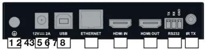
1 GND - Grounding
2 Power - 12V / 2A DC power supply input
3 PS/2 USB for KVM
4 Ethernet - TCP/IP Connector
5 HDMI IN - Connect to HDMI source
6 HDMI OUT - HDMI Local By-pass Out
7 RS232 - Connect to a RS232 device
ii. NHD-IP-RX Receiver

1 Mode Switcher - Should be set to Normal mode unless instructed by WyreStorm support
2 Power LED - Constantly lit red when the unit is powered on
3 Link LED - Constantly lit blue when the Transmitter and Receiver are linked
4 PS/2 USB for KVM
5 PS/2 USB for KVM

1 GND - Grounding
2 Power - 12V / 2A DC power supply input
3 PS/2 USB for KVM
4 PS/2 USB for KVM
5 Ethernet - TCP/IP Connector
6 RS232 - Connect to a RS232 device
7 Audio Out - Audio break out
8 HDMI Out - HDMI Local By-pass Out
7. Connection
KEY

CAT 5e/6 100M/328FT HDMI PS/2 USB FOR KVM RS232

6
CONTROLLER

BLU RAY

6


Cat5e Wiring Guide
The quality for every
essential. Poor terminations leads to intermittent performance and longer install times.

Attention Ensure good quality cabling is used throughout your system, with no electrical interference, bends, twists, kinks, or other issues that may interfere with signal transmission, including the use of patch panels or wall outlets. Cable connectors should also be in good condition and correctly terminated to required standards, with straight cable runs used where possible and plugs securely connected to ports without straining port enclosures.
The presence of any of these factors in your system can jeopardize successful signal distribution and should be eliminated wherever possible.
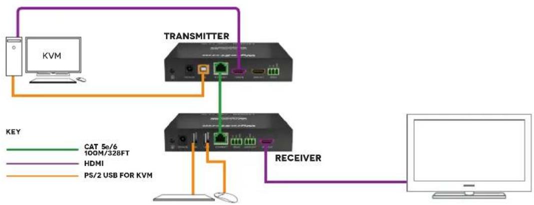
1 Connect an HDMI source (such as Blu-ray, Satellite/Cable receiver, media server, computer etc.) to any NHD-IP-TX transmitters to be used with a good quality HDMI cable, ensuring firm port connection.
2 Connect the computer to be used for KVM to the transmitter with a good quality USB cable.
3 Connect RS232 from the receiver to the display.
4 Connect an HDMI display to the receiver with a good quality HDMI cable.
5 Connect USB control devices (keyboard, mouse) to the USB of the receiver.
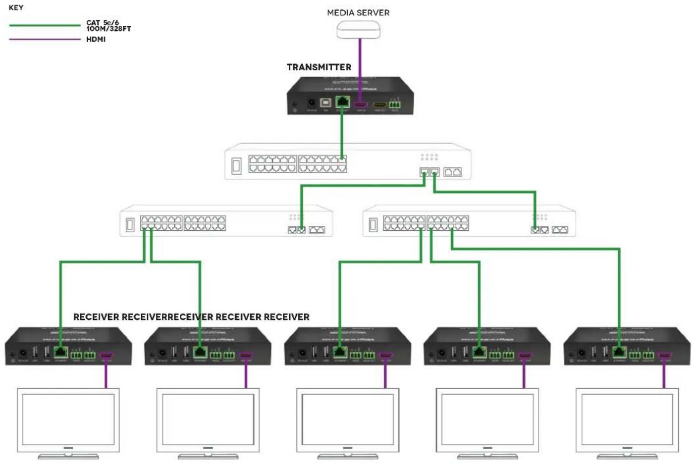
6 Connect good quality, well terminated CAT5e/6 cables of no more than 100m/328ft between the transmitter (TX), receiver (RX) and Controller (CTL) - if in use.
7 Plug in 12V DC power supplies to the TX & RX units. (Not required to the RX if using PoE as power to will be supplied via the TX).
8 Plug in 5V DC power supply to the CTL - unit if in use.
8. Typical Application
i. One Transmitter To One Receiver
flowchart
graph TD
    A["KVM"] --> B["TRANSMITTER"]
    B --> C["RECEIVER"]
    C --> D["Computer"]
ii. One Transmitter To Multiple Receivers
flowchart
graph TD
    A["TRANSMITTER"] --> B["Media Server"]
    B --> C1["RECEIVER"]
    B --> C2["RECEIVER"]
    B --> C3["RECEIVER"]
    B --> C4["RECEIVER"]
    B --> C5["RECEIVER"]
    B --> C6["RECEIVER"]
    B --> C7["RECEIVER"]
    B --> C8["RECEIVER"]
    B --> C9["RECEIVER"]
    B --> C10["RECEIVER"]
    B --> C11["RECEIVER"]
    B --> C12["RECEIVER"]
    B --> C13["RECEIVER"]
    B --> C14["RECEIVER"]
    B --> C15["RECEIVER"]
    B --> C16["RECEIVER"]
    B --> C17["RECEIVER"]
    B --> C18["RECEIVER"]
    B --> C19["RECEIVER"]
    B --> C20["RECEIVER"]
    B --> C21["RECEIVER"]
    B --> C22["RECEIVER"]
    B --> C23["RECEIVER"]
    B --> C24["RECEIVER"]
    B --> C25["RECEIVER"]
    B --> C26["RECEIVER"]
    B --> C27["RECEIVER"]
    B --> C28["RECEIVER"]
    B --> C29["RECEIVER"]
    B --> C30["RECEIVER"]
    B --> C31["RECEIVER"]
    B --> C32["RECEIVER"]
    B --> C33["RECEIVER"]
    B --> C34["RECEIVER"]
    B --> C35["RECEIVER"]
    B --> C36["RECEIVER"]
    B --> C37["RECEIVER"]
    B --> C38["RECEIVER"]
    B --> C39["RECEIVER"]
    B --> C40["RECEIVER"]
    B --> C41["RECEIVER"]
    B --> C42["RECEIVER"]
    B --> C43["RECEIVER"]
    B --> C44["RECEIVER"]
    B --> C45["RECEIVER"]
    B --> C46["RECEIVER"]
    B --> C47["RECEIVER"]
    B --> C48["RECEIVER"]
    B --> C49["RECEIVER"]
    B --> C50["RECEIVER"]
    B --> C51["RECEIVER"]
    B --> C52["RECEIVER"]
    B --> C53["RECEIVER"]
    B --> C54["RECEIVER"]
    B --> C55["RECEIVER"]
    B --> C56["RECEIVER"]
    B --> C57["RECEIVER"]
    B --> C58["RECEIVER"]
    B --> C59["RECEIVER"]
    B --> C60["RECEIVER"]
    B --> C61["RECEIVER"]
    B --> C62["RECEIVER"]
    B --> C63["RECEIVER"]
    B --> C64["RECEIVER"]
    B --> C65["RECEIVER"]
    B --> C66["RECEIVER"]
    B --> C67["RECEIVER"]
    B --> C68["RECEIVER"]
    B --> C69["RECEIVER"]
    B --> C70["RECEIVER"]
iii. Multiple Transmitters To Multiple Receivers

flowchart
graph TD
    A["BLU - RAY"] --> B["TRANSMITTER"]
    C["MEDIA SERVER"] --> D["TRANSMITTER TRANSMITTER"]
    E["BLU - RAY"] --> F["TRANSMITTER"]
    G["PC"] --> H["Receiver"]
    G --> I["Receiver Receiver Receiver"]
    G --> J["Receiver Receiver Receiver"]
    G --> K["Computer"]
iv. Video Wall

flowchart
graph TD
    A["BLU - RAY"] --> B["TRANSMITTER"]
    A --> C["TRANSMITTER"]
    B --> D["Switch"]
    C --> D
    D --> E["Receiver"]
    D --> F["Receiver"]
    E --> G["Computer"]
    F --> G
    G --> H["Receiver"]
    H --> I["Receiver"]
    I --> J["Receiver"]
    J --> K["Receiver"]
    K --> L["Blu - RAY"]
9. Switch Settings & Requirements
NetworkHD can be operated with any Gigabit Smart switch to ensure the overall switching capacity or backplane capacity meets the requirements of the number of transmitters/receivers included on the network.
Each NHD-IP-TX transmitter will produce up to 150Mb/s of data > therefore 10 x transmitters will require 10 x 150Mb/s = 1.5 Gbps.
Attention If you are unsure about the network requirements for your NetworkHD system please contact WyreStorm or your local WyreStorm distribution partner for support.
WyreStorm are not liable if network bandwidth is to blame for poor performance from the NetworkHD system.
NetworkHD does not require multiple VLANs to be configured. Third-party controllers communicate directly with the NetworkHD NHD-IP-CTL rather the Ethernet switch.
Visit wyrestorm.com for guides on detailed switch configuration and recommended switch suggestions for different sized NetworkHD systems.
CISCO SG300 + SG500 series switches
Navigate to the switches web browser configuration interface and follow these steps:
1 Enable Bridge Multicast Filtering Status in Multicast > Properties.
2 Enable IGMP Snooping Status in Multicast > IGMP Snooping.
3 In Multicast > IGMP Snooping select the VLAN NetworkHD is attached to and press Edit > Enable IGMP Snooping Status, Enable IGMP Querier Status, Select IGMP Querier Version IGMPv2.
4 In Multicast > Forward All > Set to Forbidden any ports that have devices connected that are not NetworkHD components, including PC's and third party control systems.
Ensure that settings are saved to the boot configuration or else they will be lost when the switch is power cycled.
Dell PowerConnect 2800 series switches
Navigate to the switches web browser configuration interface and follow these steps:
1 Navigate to Switching > Multicast Support > Unregistered Multicast > Edit and set Unregistered multicast to Filtering.
2 Navigate to Switching > Multicast Support > Global Parameters and set both Bridge Multicast Filtering and IGMP Snooping Status to Enable.
3 Navigate to Switching > Multicast Support > IGMP Snooping and set IGMP Snooping Status to Enable, set IGMP Querier Status to Enable.
4 Navigate to Switching > Multicast Support > Unregistered Multicast > Summery and Select all - Press Apply.
Ensure that settings are saved to the boot configuration or else they will be lost when the switch is power cycled.
Hewlett Packard 1810 series switches
Navigate to the switches web browser configuration interface and follow these steps:
1 Navigate to Network > IGMP Snooping > Advanced and set IGMP Snooping to Enable and select Apply.
2 In Network > IGMP Snooping > Advanced click the icon under Operation and in the following screen set both IGMP Snooping and Querier to Enabled. Click Apply.
3 For any ports that have devices connected that are not NetworkHD components, including PC's and third party control systems navigate to Network > IGMP Snooping > Basic and select the port from the Port drop down menu, Enable Fast Leave and click Apply.
Ensure that settings are all saved to the Boot ROM by pressing Save in the top right hand corner of the web UI.
10. NHD-IP-CTL Browser Configuration & Control
Ensure all NetworkHD components are connected to the network and powered up correctly.
Attention If you receive a 'server unavailable' system message after entering this address into your browser, ensure your PC is on the same subnet as the CTL box by following these steps:
1 Click Start menu, go to Control Panel > Network and Sharing center > Change Adapter Settings > Local Area Connection. Right click and choose Properties.

2 Highlight Internet Protocol Version 4 (TCP/IPv4) then click Properties
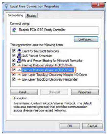
3 Check Use the following IP address, for the IP address enter 192.168.11.x (if unsure use 192.168.11.5) Enter subnet mask number 255.255.0.0 Click OK, then click OK again.
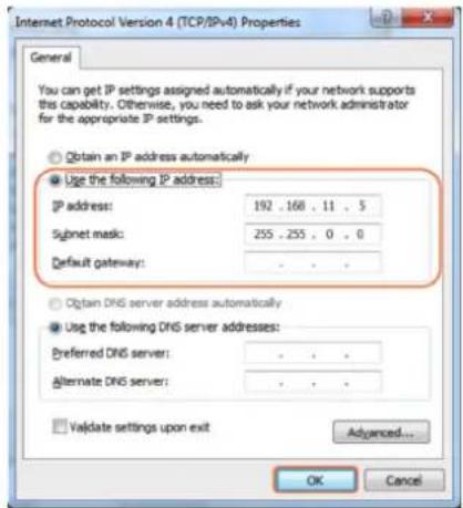
4 Return to your browser and try entering the default IP again (192.168.11.243)
i. Matrix Switching Commands
Tabs at the top of the Home Screen page are used to access settings for Matrix, TX/RX Settings and System Settings. All pages display Telnet API boxes where commands can be entered from the NetworkHD API.

1 Click the Load Matrix button, and the table of devices will appear with TX units across the top and the RX down the left hand side.
2 Press the box that links each TX & RX to test switching of the video to each RX. Devices who's names starts with EX131 are transmitters where as devices that start EX141 are receivers


Device online

Device offline

A green bar represents corresponding TX and RX are connected.
Clicking the green bar changes colour to clear to signify the corresponding TX and RX are disconnected.

A red bar denotes TX/RX connection is being processed

A clear bar signifies corresponding TX and RX are not connected. Click to connect.
Attention To remove unwanted TX or RX units from the matrix either reset the device or use the API command: config set device remove name (name is the alias or the device number). Please note resetting the device will clear the alias names of all devices on the CTL.
ii. TX/RX Settings
The TX/RX Settings section enables IP settings and alias of each TX and RX to be configured as well as rebooting the system and factory resetting the devices.
Get started by selecting the device to be configured from the list displayed and configure options as below:
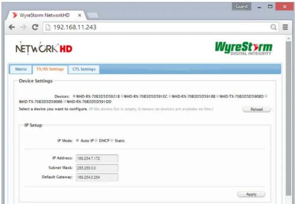
| GUI Element Description |
| Auto IP Obtain IP address automatically |
| DHCP IP address assigned by DHCP server |
| Static IP address manually configured |
| IP Address IP address of TX/RX |
| Subnet Mask Subnet mask of TX/RX |
| Default Gateway Default gateway of TX/RX. |
iii. Alias
Attention Changing the IP address of TX/RX devices requires a restart for the settings to take affect. Please use the reboot button at the bottom of TX/RX Settings page
Alias' can be used to make identification of system components easier e.g. TV12 or Bluray1. They can also be used instead of device identifiers in API commands.

| GUI Element Description |
| Alias Rename TX/RX alias for easier identification and use from API commands |
Attention Alias cannot contain any of the following symbols or combinations of letters/numbers: ',' ;' _ '@', '*, '&', 'EX131', 'EX363', 'EX373', 'EX383', 'EX393', 'TX', 'EX141', 'EX403', 'RX', '', 'NHD'.
iv. Commands

| GUI Element Description |
| Factory Default Restore TX/RX to factory default settings |
| Reboot Reboot TX/RX |
-
CTL Settings contains the settings for the IP control box itself, comprising of two separate network connections for communication with RX/TX devices and communication to the PC/control system.
-
Each setting must be on the same subnet as other devices to enable communication between all devices.
-
The default Auto IP setting is recommended for RX & TX communication - devices will use Bonjour to discover each other.
11. NetworkHD Console Configuration
Attention Included in the download package is the Bonjour SDK installer. This must be installed prior to installing the NetworkHD Console software.
i. NetworkHD Console Software Installation
1 Download the latest installation package of the NetworkHD Configuration Software from wyrestorm.com and double-click NetworkHDConsole.exe to start the tool.
Attention Your operating System must be Windows XP or later.
2 The NHD-IP-TX & NHD-IP-RX are configured by default to IP addresses in the range of 169.254.xxx.xxx, commonly referred to as Auto IP addresses. This is not a DHCP assigned address.
This addressing enables the NHD-IP-CTL to automatically discover NHD TX & RX units without any configuration on any network. Changing an RX or TX devices IP settings will prevent this auto discovery and the system components will require a reset.
NOTE The example below is based on operation using Windows 7 - steps may differ slightly depending on your operating system.
Attention NetworkHDConsole.exe is Windows only. For configuration from other operating systems the NHD-IP-CTL must be used. If a 'Windows Security Alert' appears, check both boxes and click 'Allow access' (with Administration Authority)

3 Click Start menu, go to Control Panel > Network and Sharing center > Change Adapter Settings > Local Area Connection. Right click and choose Properties.

4 Highlight Internet Protocol Version 4 (TCP/IPv4) then click Properties

5 Check Use the following IP address, for the IP address enter 169.254.xx.xx (if unsure use 169.254.2.5) Enter subnet mask number 255.255.0.0 Click OK, then click OK again.

ii. Searching for devices
1 Open the NetworkHD – HDMI over IP Console and click Search in the Device list area to begin the search – a green progress bar will illustrate process % remaining.
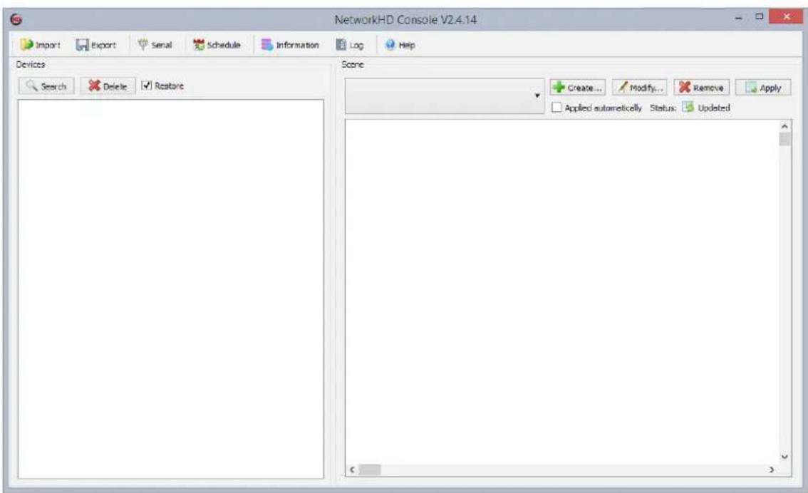
2 When the search is complete authenticated devices will be displayed in the Devices area. Restore is checked by default.

Attention If no devices are found, please refer to #1 of the Troubleshooting section of this guide.
iii. Setting Device Parameters
Right click a device in Devices - all available functions are displayed in the pop-up menu.

| Operation Description | |
| Modify Modify device parameters - available only when a single device is selected. | |
| Update | Update device status (such as Alias, Type, etc.) - valid when one or more devices are selected. |
| Delete Delete devices - valid when one or more devices are selected. | |
| Turn on OSD | Turn on On-screen Display - identifies which device is connected to TX. For example, highlight a TX, choose Turn On OSD, the device which TX connected to will display “123456”. |
| Turn Off OSD Turn off On-screen Display. | |
| Reset | Restore device to factory settings. After a factory Reset, it is recommended to press Delete and then Search to discover the device again. This may require you to change your computer IP address. |
| Reset EDID | Reset Extended Display Identification Data - valid when a TX device is selected. |
| Restart Restart device. | |
iv. Device Settings
Right click a device in Devices and choose Modify, the Device settings dialog box is displayed.

| GUI Element Description | |
| Devices Current device | |
| Host Name ID Host Name ID - generated by the system and cannot be changed | |
| Alias User-defined device name containing a maximum of 80 characters | |
| IP Address Device IP address - can be set only when static mode is selected | |
| Subnet Mask Subnet mask for the device - can be set only when static mode is selected | |
| Auto Obtain IP address automatically | |
| DHCP IP address assigned by DHCP server in router or switch | |
| Static | IP address is manually configured - if Static is chosen, enter 255.255.0.0 in Subnet Mask |
Attention Restart the TX or RX device after making any changes to the IP address for the settings to take affect. You may need to re-search for the device after it has restarted.
v. Creating Scenes
Scenes are preset configurations of matrix routing or video walls that can be recalled at any time.
Connecting Devices
The Scene displays the current status of devices. TX and RX can be moved from the left devices list to specific cells in the right table and apply the scene setting.
1 Create a Scene: Click the Create button to create a 2 x 2 scene – the name of the scene can be changed if desired.


vi. Sample Video Wall Set Up
Video Wall mode combines multiple display (RX) devices to show a complete video source. Select multiple display devices in the scene setting interface, and combine the cells as follows to configure the Video Wall – see below for 2 x 2 scene as an example:
Preparation
- 2 x NHD-IP-TX Transmitters
• 4 x NHD-IP-RX Receivers - Smart Ethernet Switch
• HDMI source such as a Blu-ray player - 4 x LCD display panels
• HDMI and Ethernet cables

flowchart
graph TD
    A["BLU - RAY"] --> B["TRANSMITTER"]
    B --> C["TRANSMITTER"]
    C --> D["Network Port 1"]
    D --> E["RECEIVER"]
    E --> F["RECEIVER"]
    F --> G["RECEIVER"]
    G --> H["RECEIVER"]
    H --> I["RECEIVER"]
    I --> J["RECEIVER"]
    J --> K["RECEIVER"]
    K --> L["RECEIVER"]
    L --> M["RECEIVER"]
    M --> N["RECEIVER"]
    N --> O["RECEIVER"]
    O --> P["RECEIVER"]
    P --> Q["RECEIVER"]
    Q --> R["RECEIVER"]
    R --> S["RECEIVER"]
    S --> T["RECEIVER"]
    T --> U["RECEIVER"]
    U --> V["RECEIVER"]
    V --> W["RECEIVER"]
    W --> X["RECEIVER"]
    X --> Y["RECEIVER"]
1 Connect the Blu-ray player to HDMI IN port of TX1 with an HDMI cable and connect HDMI OUT port of TX1 to HDMI IN port of TX2.
2 Connect TX1 and TX2 to the Switch with Ethernet cables.
3 Connect RX1, RX2, RX3, and RX4 to the Switch with Ethernet cables.
4 Connect HDMI OUT port of RX1, RX2, RX3, RX4 to the display devices with HDMI cables.
5 Power on all devices
vii. Video Wall Configuration
1 Link the Devices: To link TX and RX devices, highlight the first cell and right click > select Change TX and select TX1. Then select Change RX and select RX1.
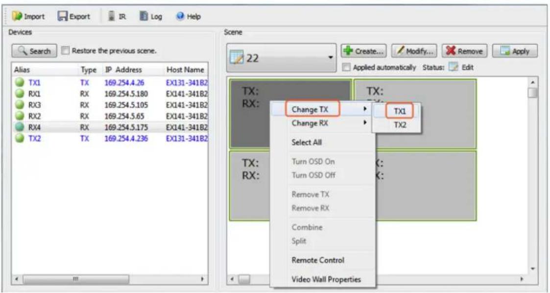
Repeat for the remaining Receivers.


The highlight color will change to indicate all cells have been selected
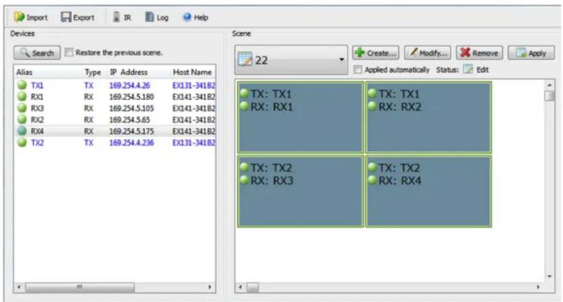
Now right click the cells again and select Combine.
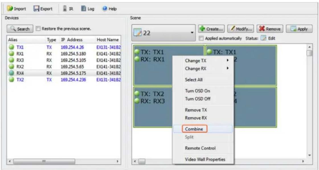
4 Confirm Wall Properties: Clicking Combine brings up the Video Wall Properties screen. Check Multi Host Mode > input a name of choice and click OK.

vii. Video Wall Properties
![8x8 Video Wall [vw] e Video Wall [vw] Basic Settings Advanced Settings Name: 12 Bezel and Gap Compensation OW OW: 0 OH: 0 VW: 0 VH: 0 HA VW HO UNIT: 0.1mm Apply OK Cancel Save](/content/2026/05/831867/images/7fa7e70aa938a9d49db7665407d8c5007be8652669262535c955ffbb647a4e2e.jpg)
| GUI Element Description | |
| Name Name the Video Wall | |
| Single Host Mode Single video-source mode - assign same video-source to all cells. | |
| Multi Host Mode | Multiple video-source mode – assign different cell rows with different video sources (recommended setting) |
| OW, OH, VH, VW Set Bezel and Gap Compensation of displays | |
viii. Configuration File Management
When closing the configuration tool, the software will save a configuration file default.hoi in the software installation directory. On next loading the software will automatically read the configuration file.
For windows XP, it is saved in C:\Documents and Settings#user#\Local Settings\Application Data\HDMIoverIP
For Windows Vista or later, it is saved in C:\Users#user#\AppData\Local\HDMIoverIP
Attention #user# means the current user of the operating system.
Attention Do not modify or delete the default.hoi. file or the software will report an error and refuse to initialize.
In addition, you can click Export to save the configuration file to a specified directory, and click Import to import the configuration file from this directory.
The log records the tool operation and device communication information, which can be used for troubleshooting.
![2014-03-17 00:02:29 - read param name="vm_moninfo_ht", value="vw_moninfo_ht" not defined. 2014-03-17 00:02:29 - Device(EX131-341B22800072) send data succeed [./asparam g vw_moninfo_va ] 2014-03-17 00:02:29 - Device(EX131-341B22800072) recv data ["vw_moninfo_ht" not defined/usr/local/bin # ./asparam g] 2014-03-17 00:02:29 - Device(EX131-341B22800072) recv data ["vw_moninfo_ht" not defined/usr/local/bin # ./asparam g vw_moninfo_va "vm_moninfo_va" not defined/usr/local/bin # ] 2014-03-17 00:02:29 - read param name="vm_moninfo_vt", value="vw_moninfo_vt" not defined. 2014-03-17 00:02:29 - Device(EX131-341B22800072) send data succeed [./asparam g vw_moninfo_vt ] 2014-03-17 00:02:29 - Device(EX131-341B22800072) recv data ["vw_moninfo_vt" not defined/usr/local/bin # ./asparam g] 2014-03-17 00:02:29 - Device(EX131-341B22800072) recv data ["vw_moninfo_vt" not defined/usr/local/bin # ./asparam g vw_moninfo_vt "vm_moninfo_vt" not defined/usr/local/bin # ] 2014-03-17 00:02:29 - read param name="vm_moninfo_vt", value="vw_moninfo_vt" not defined. 2014-03-17 00:02:29 - Device(EX131-341B22800072) send data succeed [./asparam g vw_v_shift ] 2014-03-17 00:02:29 - Device(EX131-341B22800072) recv data ["vw_moninfo_vt" not defined/usr/local/bin # ./asparam g" 2014-03-17 00:02:29 - Device(EX131-341B22800072) recv data ["vw_moninfo_vt" not defined/usr/local/bin # ./asparam g vw_v_shift "vm_v_shift" not defined/usr/local/bin # ] 2014-03-17 00:02:29 - read param name="vm_v_shift", value="vw_v_shift" not defined. 2014-03-17 00:02:29 - Device(EX131-341B22800072) send data succeed [cat /sys/devices/platform/display/monitor_info ] 2014-03-17 00:02:29 - Device(EX131-341B22800072) recv data ["vw_v_shift" not defined/usr/local/bin # cat /sys/device] 2014-03-17 00:02:30 - Device(EX131-341B22800072) recv data ["vw_v_shift" not defined/usr/local/bin # cat /sys/devices/platform/display/monitor_info attached=m /.av/local/bin # ] 2014-03-17 00:02:30 - Device(EX131-341B22800072) is updated. 2014-03-17 00:02:30 - AI devices are updated. 2014-03-17 00:02:30 - Start restoring scene... 2014-03-17 00:02:30 - The scene is restored. 2014-03-17 00:02:30 - The search is complete.](/content/2026/05/831867/images/fb9aa7eaa8f938f1d5dee496f8ec59aea6f896f5640e0086137c3e71517e46c1.jpg)
12. Troubleshooting
1) If NetworkHD software console cannot find any devices on the network - If following the network settings advice in sections 10 through 14 above does not yield any devices, check your Windows Firewall settings. Using Windows 7 as an example (Other versions of Windows may differ):
- Click Start menu, go to Control Panel > System and Security > Windows Firewall > Allowed Programs, highlight HDMI over IP Console, check Home/Work (Private) and Public.

- Check the IP address and subnet mask of the PC. The network segment for IP address is 169.254.x.x and the subnet mask is 255.255.0.0, the PC and Transmitter/Receiver should be in the same network segment. (See section 11.)
- Check the settings of the switch match those in the Switch Configuration Guides available from wyrestorm.com
- Ensure that the Bonjour SDK software has been installed on the machine you are using - the installer is available in the NetworkHD software console installation file.
3) If you are unable to access the web management UI
- Check the IP address of your computer. The default IP address of the IP Control Box is 192.168.11.243, so the IP address of the computer should be 192.168.11.X.
- Check the Web browser. We recommend you use Firefox, Opera, Safari Internet Explorer 11 or Chrome. If the problem persists, try to upgrade you browser to the latest version.
- Perform a reset on the NHD-IP-CTL by holding down the reset button on the front of the device.
4) If no devices appear in the Matrix or TX/RX Settings page...
- Ensure the devices are powered up and connected to the same network
- Ensure that the network settings in the router are correct for those set in the RX/TX units
- Refresh the browser
- Reboot all system components including the NHD-IP-CTL
- Perform a reset on the NHD-IP-CTL by holding down the reset button on the front of the device
5) If you do not see an image on the display...
- Screen is completely blank: Check the screen is on and the correct input is selected, ensure the Rx is powered and the lights are stable on the front. Replace the HDMI for a tested cable.
- The message on the screen reports one of the following:
| Message Possible Causes Solutions | ||
| Remote IP: unknown | RX restored to default settings Configure TX and RX through HDMI over IP console | |
| RX being rebooted Wait until RX is rebooted to view the picture | ||
| No instructions are displayed | Poor cable connection to RX or TV setting) Insert the HDMI cable into RX or TV again | |
| Waiting for video source - standby | Poor cable connection to TX or input source | Insert the HDMI cable into TX or input source again |
| Network link is down Poor | cable connection to RX or switch Insert the network cable into RX or switch again | |
| Trying to find the transmitter | RX trying to find the Transmitter Wait until the picture is displayed | |
| Poor cable connection to TX Insert the network cable into the TX again | ||
| TX/RX not linked Configure TX and RX through HDMI over IP console | ||
- Only part of the Image is displayed: The device is in video wall mode, send a commend to exit the device from video
6) If you cannot set a device Alias...
A device may have previously been connected to the NHD-IP-CTL with that Alias.
You will need to factory reset the CTL for it to lose that alias, be aware of alias conflicts if that other device is still connected but powered down.
7) If the RX device continuously reboots...
The RX is set to DHCP but it cannot find a DHCP server. You must connect the unit to a DHCP server so that it can finishing initialising. You will then be able to change the IP settings.
13. Additional Information
Further information about NetworkHD including system configuration & switch configuration guides as well as control drivers and Enado templates can be found at wyrestorm.com.
14. FAQs
What compression technology is utilised in NetworkHD?
NetworkHD utilises high quality JPEG2000 compression algorithm to produce very high quality images that are indistinguishable from the original at normal viewing distances. Audio is compressed using the high quality JPAC algorithm for lossless audio quality.
What resolution audio & video does NetworkHD?
NetworkHD supports up to full HD 1080P HDMI video inputs and stereo audio.
How many RX & TX units can I use in a NetworkHD system?
NetworkHD is a highly scalable system tested with up to 1000 TX/RX devices however the theoretical limits of inputs to outputs is 3000 inputs to 6000 outputs.
15. Maintenance
Clean this unit with a soft, dry cloth only. Never use alcohol, paint thinner or other harsh chemicals.
16. Provided Service
-
Damage requiring service: This unit should be serviced by a qualified service personnel if:
-
The power supply or AC adaptor has been damaged.
- Objects or liquid have gotten into the unit.
• The unit has been exposed to rain. - The unit does not operate normally or exhibits a marked change in performance.
-
The unit has been dropped or the cabinet damaged.
-
Servicing Personnel: Do not attempt to service the unit beyond that described in these operating instructions. Refer all other servicing to authorised servicing personnel.
-
Replacement Parts: When parts need replacing, ensure parts approved by the manufacturer are used – either those specified by the manufacturer or parts possessing the same characteristics as the original parts. Be aware – unauthorised substitutes may result in fire, electric shock, or other hazards and will invalidate your warranty.
-
Safety Check: After repairs or service, ask the service personnel to perform safety checks to confirm the unit is in proper working condition. When shipping the unit, carefully pack and send it prepaid, with adequate insurance and preferably in the original packaging. Please include a document or letter detailing the reason for return and include a daytime telephone number and/or email address where you can be contacted.
17. Mail-in-service
When shipping the unit, carefully pack and send it prepaid, with adequate insurance and preferably in the original packaging. Please include a document or letter detailing the reason for return and include a daytime telephone number and/or email address where you can be contacted.
If repair is required during the limited warranty period, the purchaser will be required to provide a sales receipt or other proof of purchase, indicating date and location of purchase as well as the price paid for the product. The customer will be charged for the repair of any unit received unless such information is provided.
18i. Warranty
Should you feel your product does not function adequately due to defects in materials or workmanship, we (referred to as "the warrantor") will, for the length of the period indicated below (starting from the original date of purchase) either:
a) Repair the product with new or refurbished parts.
or
b) Replace it with a new or refurbished product.
Limited warranty period:
All Wyrestorm products are covered by a 3 year PARTS and LABOUR warranty. During this period there will be no charge for unit repair, replacement of unit components or replacement of product if necessary.
The decision to repair or replace will be made by the warrantor. The purchaser must mail-in the product during the warranty period. This limited warranty only covers the product purchased as new and is extended to the original purchaser only. It is non-transferable to subsequent owners, even during the warranty period.
A purchase receipt or other proof of original purchase date is required for the limited warranty service.
18ii. Warranty Limits & Exclusions
1. This Limited Warranty ONLY COVERS failures due to defects in materials or workmanship and DOES NOT COVER normal wear and tear or cosmetic damage.
The limited warranty also DOES NOT COVER damage that occurs in shipment or failures caused by products not supplied by the warrantor, failures resulting from accident, misuse, abuse, neglect, mishandling, misapplication, alteration, incorrect installation, set-up adjustment, implementation of/to consumer controls, improper maintenance, power line surge, lightening damage, modification, service by anyone other than a manufacturer-approved service centre or factory-authorised personnel, or damage attributable to acts of God.
2. There are no express warranties except as listed under “limited warranty coverage.” The warrantor is not liable for incidental or consequential damage resulting from the use of this product or arising out of any breach of this warranty.
For example: damages for lost time, the cost of having a person/persons remove or re-install previously installed equipment, travel to and from service location, loss of or damage to media, images, data or other recorded/stored.
20. Installation Reference Log
| NHD-IP-TX TRANSMITTER | |||
| TX# IP | ADDRESS ALIAS ADDITIONAL INFO | ||
| 1 | |||
| 2 | |||
| 3 | |||
| 4 | |||
| 5 | |||
| 6 | |||
| 7 | |||
| 8 | |||
| 9 | |||
| 10 | |||
| 11 | |||
| 12 | |||
| 13 | |||
| 14 | |||
| 15 | |||
| 16 | |||
| 17 | |||
| 18 | |||
| 19 | |||
| 20 | |||
| 21 | |||
| 22 | |||
| 23 | |||
| 24 | |||
| 25 | |||
| 26 | |||
| 27 | |||
| 28 | |||
| 29 | |||
| 30 | |||
| 31 | |||
| 32 | |||
| NHD-IP-RX RECEIVER | |||
| TX# IP ADDRESS ALIAS ADDITIONAL INFO | |||
| 1 | |||
| 2 | |||
| 3 | |||
| 4 | |||
| 5 | |||
| 6 | |||
| 7 | |||
| 8 | |||
| 9 | |||
| 10 | |||
| 11 | |||
| 12 | |||
| 13 | |||
| 14 | |||
| 15 | |||
| 16 | |||
| 17 | |||
| 18 | |||
| 19 | |||
| 20 | |||
| 21 | |||
| 22 | |||
| 23 | |||
| 24 | |||
| 25 | |||
| 26 | |||
| 27 | |||
| 28 | |||
| 29 | |||
| 30 | |||
| 31 | |||
| 32 | |||
WyreStorm®
wyrestorm.com
WyreStorm Offices
North America Office: 23 Wood Road, Round Lake, NY 12151
Tel: +1 518-289-1293
EMEA Office: Unit 22, Ergo Business Park, Swindon, Wiltshire, SN3 3JW, UK
Tel: +44 (0) 1793 230 343
WyreStorm Technical Support
US: +1 844-280-WYRE (9973)
UK:- +44 (0) 1793 230 343
Email: support@wyrestorm.com
WyreStorm Technologies reserve the right to change physical appearance or technical specification of this product at any time.
Visit wyrestorm.com for the latest information on products..
150803
- WyreStorm HD over IP Solutions
- Instruction Manual
- Contents
- Introduction
- Features
- Safety Precautions
- WARNING
- Package Contents
- NHD-IP-TX
- NHD-IP-RX
- Specifications
- Panel Description
- Connection
- Cat5e Wiring Guide
- Typical Application
- i. One Transmitter To One Receiver
- ii. One Transmitter To Multiple Receivers
- iii. Multiple Transmitters To Multiple Receivers
- iv. Video Wall
- Switch Settings & Requirements
- CISCO SG300 + SG500 series switches
- Dell PowerConnect 2800 series switches
- Hewlett Packard 1810 series switches
- NHD-IP-CTL Browser Configuration & Control
- Attention If you receive a 'server unavailable' system message after entering this address into your browser, ensure your PC is on the same subnet as the CTL box by following these steps:
- i. Matrix Switching Commands
- ii. TX/RX Settings
- iii. Alias
- Attention Changing the IP address of TX/RX devices requires a restart for the settings to take affect. Please use the reboot button at the bottom of TX/RX Settings page
- iv. Commands
- NetworkHD Console Configuration
- i. NetworkHD Console Software Installation
- Attention Your operating System must be Windows XP or later.
- ii. Searching for devices
- iii. Setting Device Parameters
- iv. Device Settings
- v. Creating Scenes
- Connecting Devices
- vi. Sample Video Wall Set Up
- Preparation
- vii. Video Wall Configuration
- vii. Video Wall Properties
- viii. Configuration File Management
- Troubleshooting
- 3) If you are unable to access the web management UI
- 4) If no devices appear in the Matrix or TX/RX Settings page...
- 5) If you do not see an image on the display...
- 6) If you cannot set a device Alias...
- 7) If the RX device continuously reboots...
- Additional Information
- FAQs
- What compression technology is utilised in NetworkHD?
- What resolution audio & video does NetworkHD?
- How many RX & TX units can I use in a NetworkHD system?
- Maintenance
- Provided Service
- Mail-in-service
- 18i. Warranty
- Limited warranty period:
- 18ii. Warranty Limits & Exclusions
- This Limited Warranty ONLY COVERS failures due to defects in materials or workmanship and DOES NOT COVER normal wear and tear or cosmetic damage.
- There are no express warranties except as listed under “limited warranty coverage.” The warrantor is not liable for incidental or consequential damage resulting from the use of this product or arising out of any breach of this warranty.
- Installation Reference Log
- WyreStorm®
- WyreStorm Offices
- WyreStorm Technical Support
Brand : WyreStorm
Model : NHD-IP-RX
Category : Switch