
ACRC301H - Air conditioner APC - Free user manual and instructions
Find the device manual for free ACRC301H APC in PDF.


| Product Type | InRow Chilled Water Air Conditioner (High Temperature) |
| Model | ACRC301H |
| Brand | APC by Schneider Electric |
| Application | Data center row cooling |
| Cooling Medium | Chilled water |
| Control Interface | 4.3-inch color touchscreen display |
| Communication Protocols | Modbus (RS-485), A-Link CAN bus, Ethernet (10/100 BASE-T) |
| Network Management | Embedded Network Management Card with USB and SD slot |
| Power Supply | Single phase, dual power cords (primary and secondary) |
| Number of Fans | Up to 8 |
| Air Filters | Cleanable, top and bottom |
| Valve Type | 3-way chilled water valve with electric actuator |
| Flow Meter | Integrated electronics module |
| Dew Point Control | Optional pump (ACAC10031 or ACAC10061) |
| Auto Transfer Switch (ATS) | Integrated for power redundancy |
| Output Relays | 4 Form C relays (24 VDC, 0.6 A max) |
| Standby Input | 12/24 V AC/DC, remote standby capability |
| Temperature Sensors | Supply air (top/bottom), return air (top/bottom), water in/out, coil |
| Firmware Update | Via USB flash drive with .rcf file |
| Safety Compliance | CE marked, ISO 9001 certified |
| Service Access | Front and rear panels with lockable doors |
| Cooling Group | Up to 12 units can communicate via A-Link |
| Active Flow Controllers (AFC) | Optional, connected to A-Link bus |
Frequently Asked Questions - ACRC301H APC
User questions about ACRC301H APC
0 question about this device. Answer the ones you know or ask your own.
Ask a new question about this device
Download the instructions for your Air conditioner in PDF format for free! Find your manual ACRC301H - APC and take your electronic device back in hand. On this page are published all the documents necessary for the use of your device. ACRC301H by APC.
USER MANUAL ACRC301H APC
InRow® Chilled Water Air Conditioners (High Temperature)
ACRC301H
Service Manual
990-5190A
Release Date: October 2021
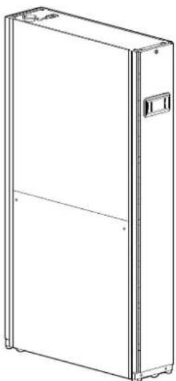
natural_image
Line drawing of a rectangular refrigerator with lid and side panel (no text or symbols)Legal Information
The Schneider Electric brand and any trademarks of Schneider Electric SE and its subsidiaries referred to in this guide are the property of Schneider Electric SE or subsidiaries. All other brands may be trademarks of their respective owners.
This guide and its content are protected under applicable copyright laws and furnished for informational use only. No part of this guide may be reproduced or transmitted in any form or by any means (electronic, mechanical, photocopying, recording, or otherwise), for any purpose, without the prior written permission of Schneider Electric.
Schneider Electric does not grant any right or license for commercial use of the or its content, except for a non-exclusive and personal license to consult it on ar is" basis. Schneider Electric products and equipment should be installed, operated, serviced, and maintained only by qualified personnel.
As standards, specifications, and designs change from time to time, information contained in this guide may be subject to change without notice.
To the extent permitted by applicable law, no responsibility or liability is assumed Schneider Electric and its subsidiaries for any errors or omissions in the information content of this material or consequences arising out of or resulting from the use information contained herein.
This manual contains general information, safety instructions, and guidance. Updates may be published from time to time and are available upon request. This manual not a substitute for the user conducting a detailed operational and site-specific development plan.
This product is for industrial use only. It should only be used for the functions for which it has been designed as set out in this manual. User must evaluate and adequate precautions to address risks associated with use of this product in environments and/or processes not specifically addressed in this manual (e.g. heavy industry, medical, marine environments, railway, etc.).
This product should be installed, configured, used, serviced, maintained, replaced o have similar work carried out on it only by suitably qualified, trained, experienced competent personnel who hold any necessary authorizations (e.g. licenses, permits or certifications) to perform such work.User must ensure that all work is carried o compliance with the manufacturer's instructions (including the product labels/ markings, technical specification manual, installation manual, and operation and maintenance manual) and with all applicable laws, regulations, standards and guidance (including standards and guidance applicable to the installation location).
All work must be carried out in a way that does not give rise to danger and use appropriate personal protective equipment (PPE).
Schneider Electric shall not be responsible for any works carried out by anyone c than Schneider Electric; or for integration or use of the product with other products (including spare parts and software) that are neither approved nor provided by Schneider Electric for such purposes; or for any non-Schneider Electric software, firmware, information or memory data contained in, stored on, or integrated with the product.
To the maximum extent permitted by applicable law, neither Schneider Electric nor any of its affiliates shall be liable for any claims, costs, losses, damages, death or injuries arising out of the improper use of this product or any failure to comply with any of the above requirements. Schneider Electric's quality management system is ISO 9001 certified and the products are marked
CE
Table of Contents
Safety....5
Important Safety Instructions — SAVE THESE INSTRUCTIONS......5
Safety Notices for All Service Procedures....6
General Information....8
Translation Reference....8
Save These Instructions....8
Manual Updates ....8
Cross-Reference Symbol Used in This Manual 8
Audience 8
Companion Manuals 9
Network and Controls....10
InRow Touchscreen and Wiring 10
Controller Area Network (CAN) Diagram (A-Link ports)....10
Active Flow Controllers (AFC)....10
Network Port 11
Modbus.... 11
Modbus Configuration—DIP Switch SW503....12
Output Relays and Standby Input....13
Communication (Building Management System) 13
User Interface Connection Panel Inventory....14
Shutdown Input Contact and Alarm Output Contact....15
Components Location 16
Piping....17
Communication 18
Cooling Group 19
Component Replacement....20
Before You Start 20
Remove Doors and Panels....20
Cleanable Air Filters 21
Control Actuator 22
Chilled Water Valve....23
Flow Meter-Electronics Module 26
Dew Point Control Pump 27
ATS Relay....29
Control Board....31
Fan Assembly 32
Fan Power Supply 33
Network Management Card....34
Display Interface....35
Temperature Sensors ....37
Updating the Firmware....38
Generating Service Passcodes 41
Dew Point Control Pump Programming....42
Troubleshooting 45
Appendix 48
Safety
Important Safety Instructions — SAVE THESE INSTRUCTIONS
Read these instructions carefully and look at the equipment to become familiar with it before trying to install, operate, service or maintain it. The following safe messages may appear throughout this manual or on the equipment to warn of potential hazards or to call attention to information that clarifies or simplifies a procedure.

The addition of this symbol to a “Danger” or “Warning” safety message indicates that an electrical hazard exists which will result in personal injury if the instructions are not followed.

This is the safety alert symbol. It is used to alert the user to potential personal injury hazards. Obey all safety messages with this symbol to avoid possible injury or death.
⚠️ DANGER
DANGER indicates a hazardous situation which, if not avoided, will result in death or serious injury.
Failure to follow these instructions will result in death or serious injury.
▲WARNING
WARNING indicates a hazardous situation which, if not avoided, could result in death or serious injury.
Failure to follow these instructions can result in death, serious injury, or equipment damage.
▲CAUTION
CAUTION indicates a hazardous situation which, if not avoided, could result in minor or moderate injury.
Failure to follow these instructions can result in injury or equipment damage.
NOTICE
NOTICE is used to address practices not related to physical injury. The safety alert symbol shall not be used with this type of safety message.
Failure to follow these instructions can result in equipment damage.
Please Note
Electrical equipment should only be installed, operated, serviced, and maintained by qualified personnel. No responsibility is assumed by Schneider Electric for an consequences arising out of the use of this material.
A qualified person is one who has skills and knowledge related to the construct installation, and operation of electrical equipment and has received safety training to recognize and avoid the hazards involved.
Always abide strictly by local laws and regulations in the place of installation.
Safety Notices for All Service Procedures
Read and adhere to the following important safety considerations when working with this equipment. Service to the components in the cooling loop should be performed only by a certified HVAC technician.
⚠️ DANGER
HAZARD OF ELECTRIC SHOCK, EXPLOSION, OR ARC FLASH
Turn off all power supplying this equipment before working on the equipment. All electrical work must be performed by qualified personnel. Apply Lockout/Tagout procedures. Do not wear jewelry when working with electrical equipment.
Failure to follow these instructions will result in death or serious injury.
⚠️ DANGER
HAZARD OF ELECTRIC SHOCK
To avoid possible personal injury or death, install and secure all access covers and hardware when service is completed.
Failure to follow these instructions will result in death or serious injury.
▲WARNING
HAZARD FROM MOVING PARTS
Keep hands, clothing, and jewelry away from moving parts. Check the equipment for foreign objects before closing the doors and starting the equipment.
Failure to follow these instructions can result in death, serious injury, or equipment damage.
▲WARNING
TIPPING HAZARD
The equipment is heavy and can easily be tipped. For safety purposes, adequate personnel must be present when moving this equipment.
Failure to follow these instructions can result in death, serious injury, or equipment damage.
▲WARNING
UNEXPECTED START-UP OF EQUIPMENT
Keep hands, clothing, and jewelry away from moving parts. Check the equipment for foreign objects before closing the doors and starting the equipment.
The equipment is heavy. For safety purposes, adequate personnel must be present when moving this equipment.
Failure to follow these instructions can result in death, serious injury, or equipment damage.
NOTICE
HAZARD TO EQUIPMENT
Circuit boards contained within this unit are sensitive to static electricity. Use one or more electrostatic-discharge device while handling the boards.
Failure to follow these instructions can result in equipment damage.
General Information
Translation Reference
The original version of this manual has been written in the English language.
Manuals written in other languages have been translated from the original English version.
Save These Instructions
This manual contains important instructions that must be followed during the installation of this equipment.
Manual Updates
Schneider Electric™ policy is one of continuous technological innovation and the company reserves the right to amend any data herein without prior notice. The images shown in this manual are for descriptive purposes only.
NOTE: Unit images and component identification information are examples only.
For any updates to this manual, please contact Schneider ^1 beforeting the related part number displayed on the manual back cover.
Cross-Reference Symbol Used in This Manual

See another section of this document or another document for more information on this subject.
Audience
This document is intended for professionally trained HVAC service personnel. It assumes that the user is experienced with the tools required to perform the service tasks described in this document and with the InRow cooling unit itself. It provides a brief introduction to the InRow system and information on how to troubleshoot and service the system.
The chapters in this manual contain the following information:
- Safety: Important safety warnings and instructions
- Communication: Information on how the system communicates with its environment and other components.
• Diagrams: Main diagrams for the system. - Troubleshooting: A list of alarms, possible problems, and solutions.
- Service Procedures: Information on how to replace or service parts in the system.
- Firmware Upgrade: Instructions on how to upgrade the system firmware.
- InRow Touchscreen Diagrams
Companion Manuals
For more information about InRow RC Chilled Water Air Conditioners, refer to the following documentation:
- InRow RC Installation Manual (ACRC301S and ACRC301H)
- InRow Chilled Water Air Conditioners Operation and Maintenance Manual (ACRC301S and ACRC301H)
• InRow Chilled Water Air Conditioners Technical Specifications
Network and Controls
InRow Touchscreen and Wiring
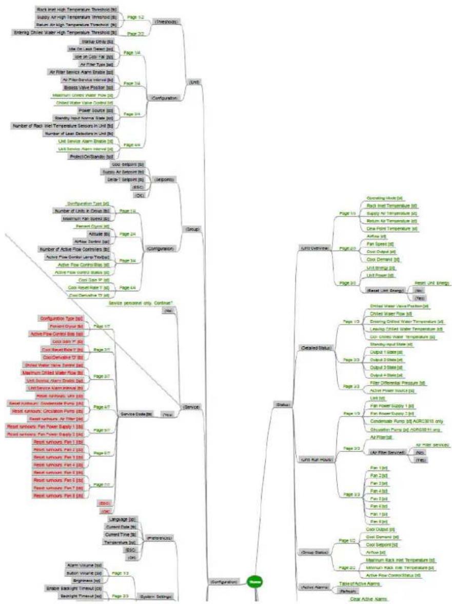
See the Appendix, page 48 to view the InRow Touchscreen Diagram and Computer Room Air Conditioning Ladder Diagram.
Controller Area Network (CAN) Diagram (A-Link ports)
NOTE: All input and output connections should be wired as Class 2 circuits.
The A-Link bus connection allows a maximum group of twelve InRow ACRC cooling units (ACRC301H or ACRC301S) to communicate with one another.
To enable the InRow ACRC301x cooling units to function as a group, link them together using a standard pin-out CAT-5 cable with RJ-45 connectors. The A-Link bus must be terminated at the first and last unit installed in the group. An A-Lir terminator is supplied with each unit.
NOTE: The maximum wire length for the entire group must not exceed 305 n (1,000 ft).
Active Flow Controllers (AFC)
If AFC units are installed in the row, they are connected to the A-Link bus as shown.
NOTICE
CAT 5 PINOUT
Devices connected on the A-Link ports should use a standard pin-out (1-1, 2-2, 3-3, 4-4, 5-5, 6-6, 7-7, 8-8) CAT5 cable only.
Failure to follow these instructions can result in equipment damage.
Network Port
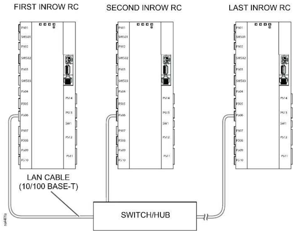
flowchart
graph TD
    subgraph FIRST_INROW_RC
        PS01["PS01"] -->|LAN CABLE (10/100 BASE-T)| SWITCH_HUB["SWITCH/HUB"]
        SW501["SW501"] --> SWITCH_HUB
        PS02["PS02"] --> SWITCH_HUB
        SW502["SW502"] --> SWITCH_HUB
        PS03["PS03"] --> SWITCH_HUB
        SW503["SW503"] --> SWITCH_HUB
        PS04["PS04"] --> SWITCH_HUB
        PS05["PS05"] --> SWITCH_HUB
        PS06["PS06"] --> SWITCH_HUB
        SW1["SW1"] --> SWITCH_HUB
        PS07["PS07"] --> SWITCH_HUB
        PS08["PS08"] --> SWITCH_HUB
        PS09["PS09"] --> SWITCH_HUB
        PS10["PS10"] --> SWITCH_HUB
    end

    subgraph SECOND_INROW_RC
        PS01["PS01"] --> SWITCH_HUB
        SW501["SW501"] --> SWITCH_HUB
        PS02["PS02"] --> SWITCH_HUB
        SW502["SW502"] --> SWITCH_HUB
        PS03["PS03"] --> SWITCH_HUB
        SW503["SW503"] --> SWITCH_HUB
        PS04["PS04"] --> SWITCH_HUB
        PS05["PS05"] & PS06["PS06"] & PS07["PS07"] & PS08["PS08"] & PS09["PS09"] & PS10["PS10"]
        PS14["PS14"] & PS13["PS13"] & SW1["SW1"] & PS12["PS12"] & PS11["PS11"]
    end

    subgraph LAST_INROW_RC
        PS01["PS01"] --> SWITCH_HUB
        SW501["SW501"] & PS02["PS02"] & SW502["SW502"] & PS03["PS03"] & SW503["SW503"] & PS04["PS04"] & PS05["PS05"] & PS14["PS14"] & PS13["PS13"] & SW1["SW1"] & PS12["PS12"] & PS11["PS11"]
    end
Modbus
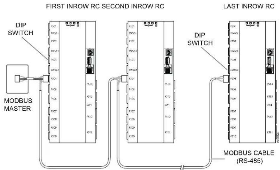
flowchart
graph LR
    A["MODBUS MASTER"] --> B["DIP SWITCH"]
    B --> C["FIRST INROW RC SECOND INROW RC"]
    C --> D["DIP SWITCH"]
    D --> E["LAST INROW RC"]
    E --> F["MODBUS CABLE (RS-485)"]
Modbus Configuration—DIP Switch SW503
Position Status Dips Switches Mode
1 and 2 Open (up)
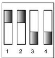
4-wire Modbus (needs TXD0-, TXD1+, RXD0-,
RXD0+, and COM connected to Modbus master)
1 and 2 Closed (down)
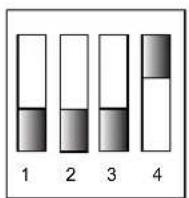
2-wire Modbus (needs TXD0-, TXD1+, and COM,
or RXD0, RXD0+, and COM)
3 and 4 Open (up)
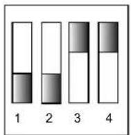
2-wire or 4-wire Modbus (no termination)
3 and 4 Closed (down)
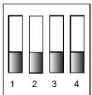
4-wire Modbus (termination enabled)
3 Closed (down)
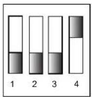
2-wire Modbus (termination enabled, position 4 must remain in the Open (up) position in 2-wire mode, or double termination will occur)
Output Relays and Standby Input
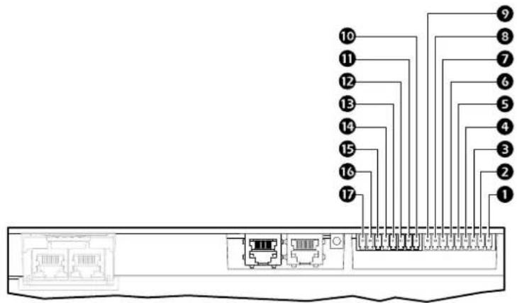
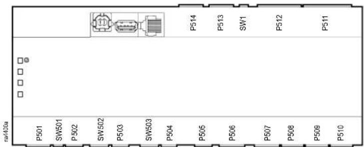
Item Description Item Description
| 1 | Output relay 1 Normally Open contact Output relay 4 N.O. | N.O. | Normally Open contact | |||
| 2 | Output relay 1 Common contact Output relay 4 COM | COM | Common contact | |||
| 3 | Output relay 1 Normally Closed contact Output relay 4 N.C. | N.C. | Normally Closed contact | |||
| 4 | Output relay 2 Normally Open contact Ground ground reference, typically N.O. | connected to the negative connection of Standby Input, when using the 12VDC or 24VDC power supply. | ||||
| 5 | Output relay 2 Common contact 12VDC Standby input 12VDC supply COM | current limited to 20mA | ||||
| 6 | Output relay 2 Normally Closed contact 24VDC Standby input 24VDC supply N.C. | current limited to 20mA | ||||
| 7 | Output relay 3 Normally Open contact Standby Input N.O. | + | Positive connection used for Standby Input | |||
| 8 | Output relay 3 Common contact Standby Input COM | - | Negative connection used for Standby Input.Typically connected to ground. | |||
| 9 | Output relay 3 Normally Closed contact N.C. |
Communication (Building Management System)
Make all electrical connections in accordance with national and local codes.
See the electrical schematic (located on the lid of the electrical box) for all electrical connections.

See the InRow RC nameplate for voltage and current requirements.
A power disconnect is required to isolate each InRow RC for maintenance and service.
All low-voltage connections, including data and control connections, must be made with properly insulated wires. The low-voltage connections must have 300-V minimum insulation.
⚠️ DANGER
HAZARD OF ELECTRIC SHOCK, EXPLOSION, OR ARC FLASH
Turn off all power supplying this equipment before working on the equipment. All electrical work must be performed by qualified personnel. Apply Lockout/Tagout procedures. Do not wear jewelry when working with electrical equipment.
Failure to follow these instructions will result in death or serious injury.
NOTE: Single phase service is required. Electrical service must conform to national and local electrical codes. The cooling unit is grounded through the power cord.
See the InRow RC nameplate for voltage and current requirements.
User Interface Connection Panel Inventory
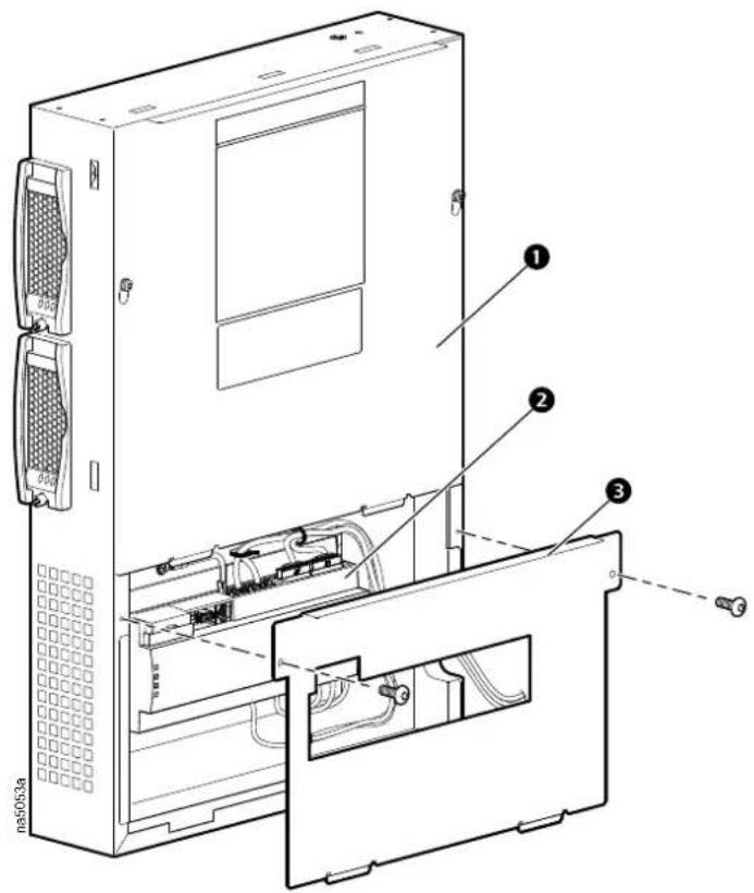
Item Description
1
Upper electrical box cover
2
User interface connection panel
3
Control module cover
Shutdown Input Contact and Alarm Output Contact
Output Relays
Four output relays connections are available. These relays can be configured, through the display interface, to various alarms detecting normal or abnormal conditions.
Output relays are Form C type, having Normally Open (N.O.), Normally Closed C.), and Common (COM) contacts.
NOTE: Output Relays are rated at 24VDC,.6A maximum.
Standby Input
Standby input allows the cooling unit to be remotely placed in Standby mode. Standby mode is configured through the display interface and can be set as a normally “active” or “not active” input.
NOTE: Standby input is rated at 12/24V AC or DC. If using field supplied voltage, the standby input consumes 10mA maximum at 24 VDC.
EXTERNAL POWER SUPPLY
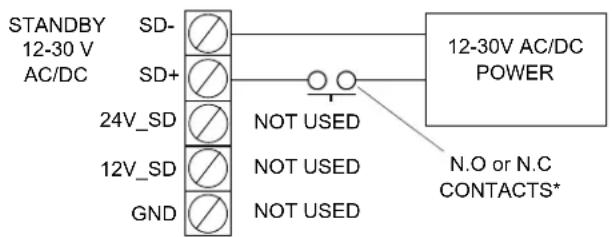
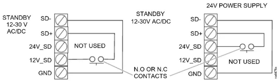
*Normally open contacts shown.
Components Location
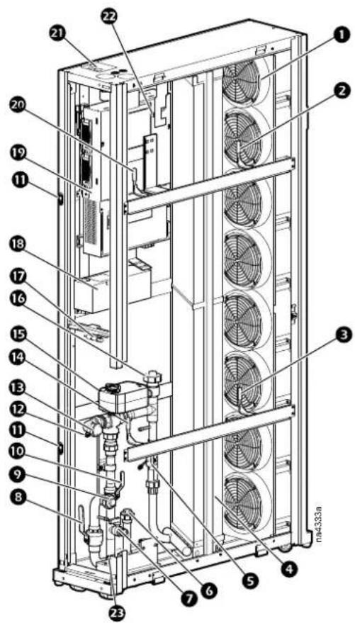
Item Description Item Description
| 1 | Fan Pipe connection, water outlet | 10 | |
| 2 | Supply air temperature sensor, top | 11 | Return air temperature sensor, bottom |
| 3 | Supply air temperature sensor, bottom | 12 | 3-way valve actuator |
| 4 | Coil Top pipe connection for optional recirculation | 13 | pump |
| 5 | Flow meter Humidity sensor | 14 | |
| 6 | Bottom pipe connection for optional recirculation pump | 18 | Auto transfer switch (ATS) box |
| 7 | Drain valve Electrical box | 19 | |
| 8 | Inlet shutoff valve (1 1/4-in.) | 20 | Return air temperature sensor, top |
| 9 | Pipe connection, water inlet Junction box, top position | ||
| 10 | 2-way valve (1-in.) bypass shut-off Schrader valve (air purging) | ||
| 11 | Rack joining brackets | 23 | Schrader valve (inlet water pressure test) |
| 12 | Schrader valve (outlet water pressure test) |
Piping
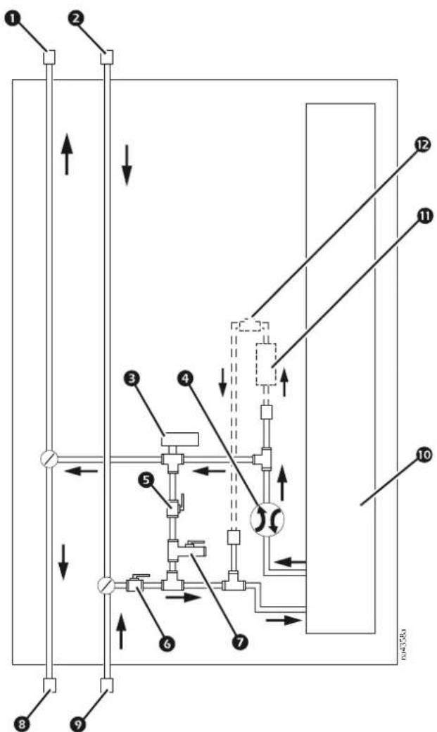
flowchart
graph TD
    A["1"] --> B["2"]
    B --> C["3"]
    C --> D["4"]
    D --> E["5"]
    E --> F["6"]
    F --> G["7"]
    G --> H["8"]
    H --> I["9"]
    I --> J["10"]
    J --> K["11"]
    K --> L["12"]
    style A fill:#f9f,stroke:#333
    style B fill:#f9f,stroke:#333
    style C fill:#f9f,stroke:#333
    style D fill:#f9f,stroke:#333
    style E fill:#f9f,stroke:#333
    style F fill:#f9f,stroke:#333
    style G fill:#f9f,stroke:#333
    style H fill:#f9f,stroke:#333
    style I fill:#f9f,stroke:#333
    style J fill:#f9f,stroke:#333
    style K fill:#f9f,stroke:#333
    style L fill:#f9f,stroke:#333
Item Description Item Description
1 Outlet water union (top piping option) Outlet water union (bottom piping option)
② Inlet water union (top piping option) Inlet water union (bottom piping option)
3-way actuator control valve—1 1/4 in. Coil
4 Flow meter 11 Circulation pump (optional)
5 Bypass shutoff valve—1 in. Circulation pump check valve (optional)
6 Inlet shutoff valve—1 1/4 in.
7 Drain valve
Communication
Interface Connection
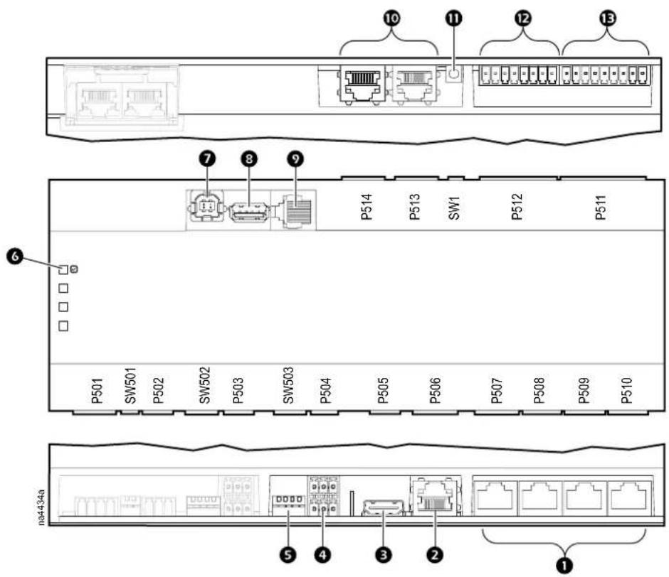
Item Description Item Description
| 1 | Universal sensor ports | 8 | USB host port |
| 2 | Network connection | 9 | Serial port |
| 3 | Touchscreen display connection A-Link port | 10 | |
| 4 | ModBus connection Reset button | 11 | |
| 5 | ModBus configuration switches Output relay 4/standby input | ||
| 6 | Processor status LED | 13 | Output relay 1–3 |
| 7 | USB device port |
Cooling Group
Once each cooling unit has been connected through the A-Link Controller Area Network (CAN) bus, the individual units can share setpoints and temperature data.
See “Cooling Group Configuration” in the InRow RC Operation and Maintenance Manual for details on setting up the cooling group on the display interface.
Network Management Card to Customer LAN
Connect the cooling unit to the customer LAN using the RJ-45 port on the dis interface connection box.

See “Network Configuration” in the InRow RC Operation and Maintenance Manual for instructions on setting up the IP address and other network settings.
Network Management Card to StruxureWare™ for Data Centers
If the cooling unit and StruxureWare are connected to the same network, StruxureWare will auto-detect the cooling unit. It is critical that the cooling unit given a unique name at either the display interface or through one of the inter-enabled by the Network Management Card for easy identification in StruxureWare. A secondary method is to identify the unit by its IP address.
Unit to Customer BMS
The cooling unit can be monitored and controlled by a building management system (BMS) using the Modbus protocol. Connect the cooling unit to your BMS using the RS-485 connector on the cooling controller.
See "Modbus" in "Electrical Connections" in the InRow RC Installation Manual for instructions on wiring the RS-485 bus to the unit.

See "Configure Modbus" in the InRow RC Operation and Maintenance Manual for instructions on how to set the unit to work with a BMS.
Shutdown Input Contact and Alarm Output Contact
The unit provides one field connection input for remote shutdown and four field connections for alarm output.
See “Shutdown input and alarm output connection” in “Electrical Connections” in the InRow RC Installation Manual for a diagram of the input and output connections.
Component Replacement
Before You Start
⚠️ DANGER
HAZARD OF ELECTRIC SHOCK, EXPLOSION, OR ARC FLASH
- Apply appropriate personal protective equipment (PPE) and follow safe electrical work practices.
- This equipment must be installed and serviced by qualified personnel only and under the supervision of personnel qualified by Schneider Electric.
- Turn off all power supplying this equipment before working on or inside the equipment.
- Replace all devices, doors, and covers before turning on power to this equipment.
Failure to follow these instructions will result in death or serious injury.
Powering down the unit
To stop the cooling unit:
Path:Main > On/Standby
- Press Command Standby
- Select Yes.
- If not logged in and Protect On/Standby is activated, a prompt will appear for you to enter your password
- The On/Standby status will now display Standby
NOTE: The unit can also be stopped via an external signal connected to the Standby Input. Removing power
Remove power to the unit by disconnecting both power cords (primary and secondary) or Lock out/Tagout the branch circuit breakers.
Remove Doors and Panels
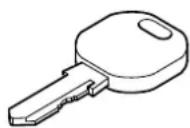
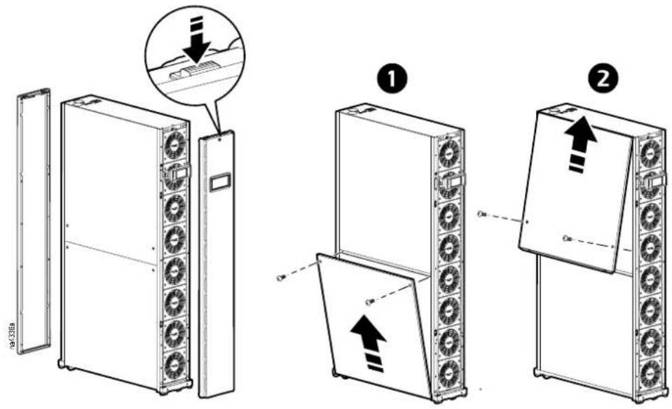
The front and rear panels must first be unlocked before they can be removed. Two keys are provided with the unit.
Cleanable Air Filters
Removal and Installation
- Starting with the top air filter, locate the pull tab and pull up and away from filter track.
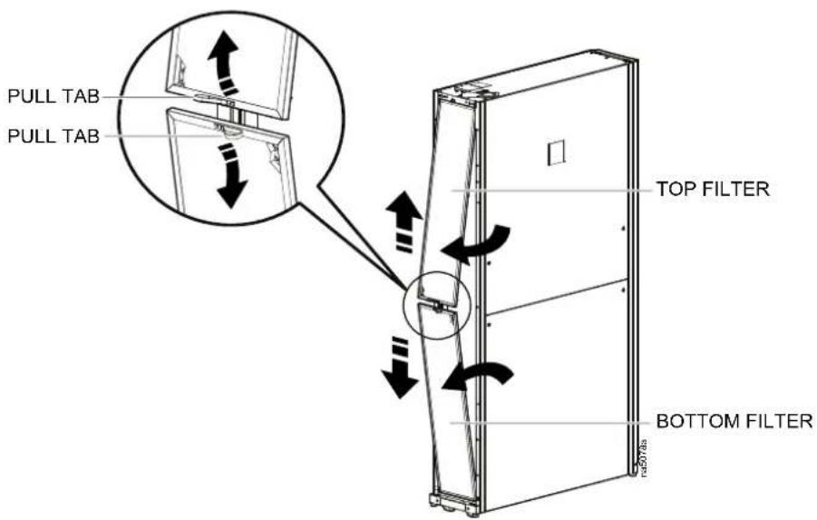
- To remove the bottom filter, locate the pull tab and pull down and away if the filter track.
- Remove dust and debris from the filter media using a vacuum with a soft brush, or rinse the filter media with low pressure water.
- Inspect the filter for damage or deterioration of the filter media. Make sure filter is dry before installing.
- Reinstall the filter.
Control Actuator
▲WARNING
HAZARD OF ELECTRIC SHOCK, EXPLOSION, OR ARC FLASH
Turn off all power supplying this equipment before working on the equipment.
Failure to follow these instructions can result in death, serious injury, or equipment damage.
Removal
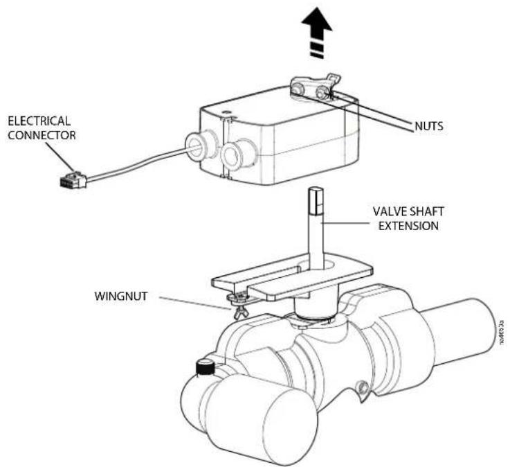
- Loosen the wing nut securing the control actuator.
- Using an Allen wrench, loosen the two nuts that secure the clamp to the va shaft extension.
- Disconnect the electrical connector.
- Slide the unit out.
Chilled Water Valve
Removal
-
Remove the rear panel and the top and bottom air filters.
-
Shut off the external water supply to the unit. Relieve the water pressure the piping using the Schrader valve.
-
Drain the water/coolant from the internal piping around the flow meter:
See Components Location, page 16.
a. Rotate the actuator to the left to full bypass.
b. Connect a hose to the drain valve at the bottom of the unit. Place the other end of the hose into a bucket.
c. Open the drain valve to drain the unit.
d. Locate the Schrader valve.
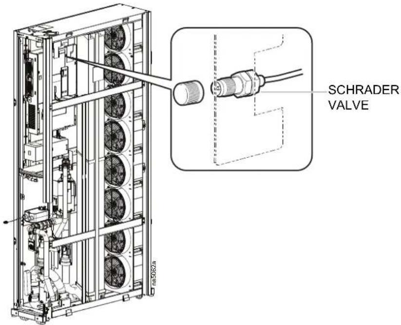
e. Slightly open the Schrader valve to allow the remaining water in the piping to drain.
f. Close the drain valve and Schrader valve after the unit is drained.
NOTE: Properly dispose of glycol in accordance with all local and nation regulations.
- Locate the actuator and chilled water valve.
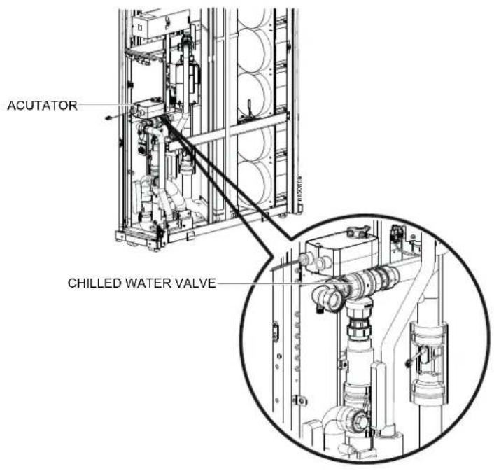
-
Remove the insulation on the chilled water valve.
-
Remove the actuator.
See Control Actuator, page 22.
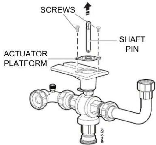
- Remove the two screws attaching the black plastic actuator platform to the chilled water valve. Remove the actuator shaft pin and black actuator platform.
- Remove the two screws and fitting securing the rotational stop to the actuate platform and remove the stop.
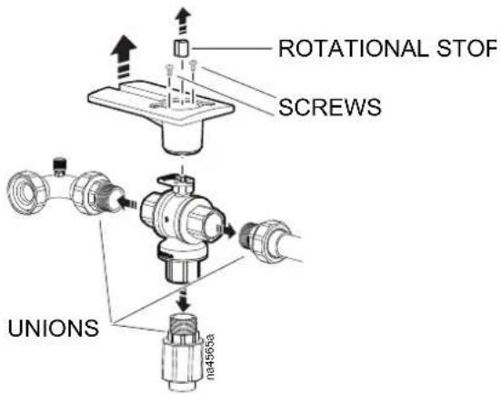
-
Loosen the unions around the valve.
-
Remove the chilled water valve.
Installation
NOTE: Before installation, the valve must be set open to flow from B to AI
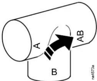
- Line the new valve up to the respective unions and tighten the three union 6.78 N-m (60 in-lb) of torque).
- Attach the black plastic actuator platform to the new chilled water valve with the two screws.
- Replace the valve actuator and bracket. Make sure that the "T" indicator of the valve shaft is in the same orientation as the "T" on the valve itself. T the set screw to 6.7 N·m (60 in·lb) of torque.
- Rotate the 3-way valve actuator back to the full cool position.
- Slightly open the top and bottom coil vent valves.
- To pressurize the piping, open the return water valve at the Cooling Distribution Unit (CDU) or in the external piping, depending on your configuration.
- Air begins to flow from the coil vents. Close the bottom coil vent when you a small stream of water. Continue to bleed the air from the top coil vent you see a small stream of water there as well, then tighten and close the
- Once all air has left the system and the vents are closed tightly, open the water supply to the unit (either at the CDU or in your external piping), rett the 3-way valve to full-bypass, and open the internal bypass and supply valves.
- Check the chilled water valve piping for leaks.
- Replace any insulation removed earlier.
- Verify proper operation.
Flow Meter-Electronics Module
⚠️ DANGER
HAZARD OF ELECTRIC SHOCK, EXPLOSION, OR ARC FLASH
Turn off all power supplying this equipment before working on the equipment. All electrical work must be performed by qualified personnel. Apply Lockout/Tagout procedures. Do not wear jewelry when working with electrical equipment.
Failure to follow these instructions will result in death or serious injury.
▲WARNING
ENGAGE INTERLOCKS
Doors and panels are equipped with locks. Locks must be engaged while the unit is operating.
Failure to follow these instructions can result in death, serious injury, or equipment damage.
NOTICE
COOLANT SPILL
Ensure the coolant lines are valved closed before removing the retaining clip. Relieve the remaining water pressure using the Schrader valve.
Failure to follow these instructions can result in equipment damage.
NOTICE
EQUIPMENT DAMAGE
During reassembly, take care not to damage or distort gaskets and o-rings.
Be sure that the gasket is properly seated in the groove of flow meter
Failure to follow these instructions can result in equipment damage.
Removal
- Drain the coolant and relieve the coolant pressure from the system.
- Remove the retaining clip from the flow meter body.
- Remove the flow meter sensor from the flow meter body.
- Remove the flow meter.
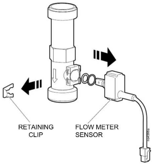
Installing and Verifying Operation
- Install the new flow meter.
- Fill the system with coolant.
- Purge air from the system.
- Turn the system "ON".
- On the display interface, go to: Main > Status > Detailed Status > Chiller Water Flow
- Navigate to the screen containing the Fluid Flow parameter.
- Ensure that the unit is reading the proper fluid flow rate.
- Replace filters and panels.
Dew Point Control Pump
⚠️ DANGER
HAZARD OF ELECTRIC SHOCK, EXPLOSION, OR ARC FLASH
Turn off all power supplying this equipment before working on the equipment. All electrical work must be performed by qualified personnel. Apply Lockout/Tagout procedures. Do not wear jewelry when working with electrical equipment.
Failure to follow these instructions will result in death or serious injury.
NOTE: Images below refer to the ACAC10031 Dew Point Control Pump kit (with Stratos model).
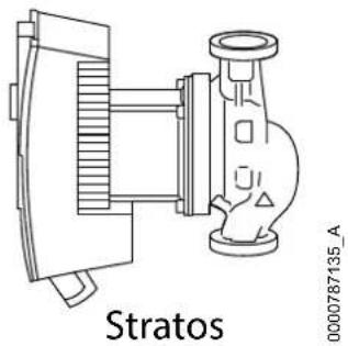
Removal with ACRC301H installed in-row
- Remove power to the unit by disconnecting both power cords (primary and secondary sources)
- Drain the water from the system.
- Remove the electrical connectors.
- Remove the grounding wire.
- Remove the two hex screws attaching the face plate to the pump controller.
- Remove the two hex screws attaching the pump controller to the pump.
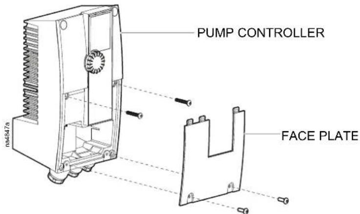
- Remove the two screws attaching the u-clamp and remove the clamp.
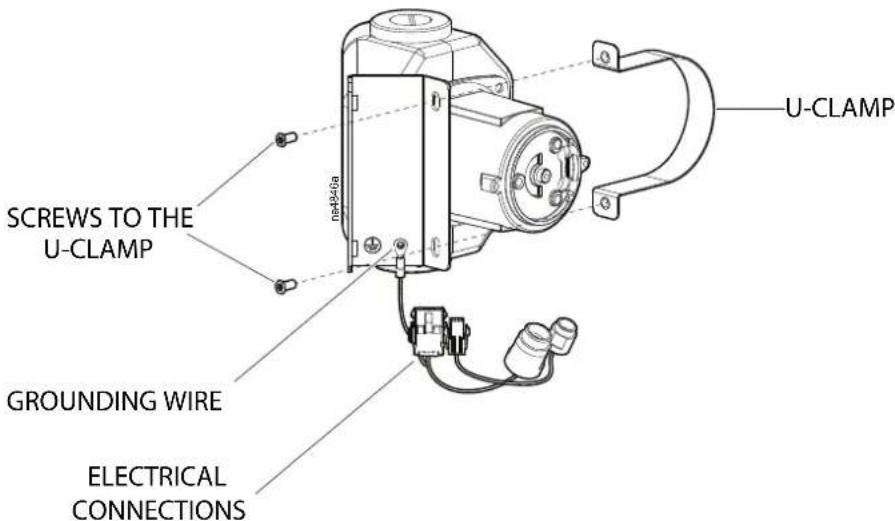
- Remove the four hex screws attaching the pump and remove the pump.
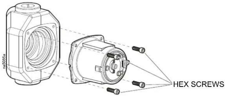
Installation
- Reverse the removal procedures.
- Restart the unit.
For details on dew point pump operation, see Dew Point Control Pump Programming, page 42.
NOTE: Images below refer to the ACAC10061 Dew Point Control Pump kit (with Stratos MAXO model).
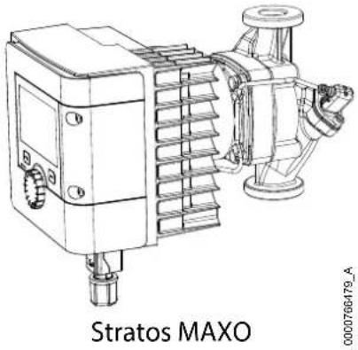
natural_image
Technical line drawing of a Stratos MAXO device with no visible text or symbols on the component itself
Refer to the ACAC10061 Installation Manual for pump installation details on the ACAC10061 Dew Point Control Pump kit (with Stratos MAXO model).
ATS Relay
⚠️ DANGER
HAZARD OF ELECTRIC SHOCK, EXPLOSION, OR ARC FLASH
Turn off all power supplying this equipment before working on the equipment. All electrical work must be performed by qualified personnel. Apply Lockout/Tagout procedures. Do not wear jewelry when working with electrical equipment.
Failure to follow these instructions will result in death or serious injury.
Removal
- Remove the ATS box cover.
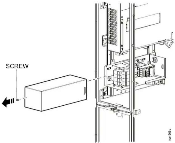
- The following graphic provides the location of ATS box components.
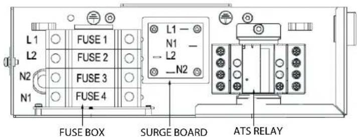
-
Remove the connecting wires.
-
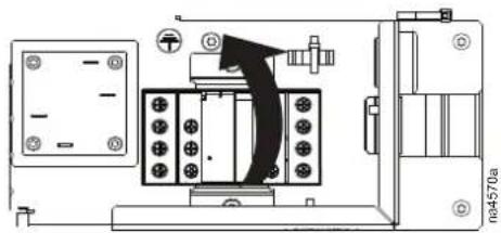
Pull down and rotate up to release the spring tension tab.
natural_image
Technical line drawing of an electrical enclosure with mounting holes and a black arrow indicating direction (no text or symbols)Control Board
⚠️ DANGER
HAZARD OF ELECTRIC SHOCK, EXPLOSION, OR ARC FLASH
Turn off all power supplying this equipment before working on the equipment. All electrical work must be performed by qualified personnel. Apply Lockout/Tagout procedures. Do not wear jewelry when working with electrical equipment.
Failure to follow these instructions will result in death or serious injury.
Removal
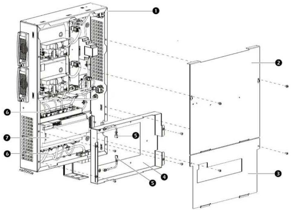
Item Description Item Description
| 1 | Electrical box | 5 | Ground wires |
| 2 | Top cover panel Factory wiring connections | 6 | |
| 3 | Customer interface cover Cooling controller | 7 | |
| 4 | Controller cover |
- Slide out the electrical box.
- Remove the screws and customer interface connection cover.
- Remove screws and top cover panel.
- Remove the sensors connecting the universal sensor input ports.
a. Remove the user display cable and the ground wire. b. Remove all other cables, i.e., A-Link, network, digital input, relay output, BMS. - Remove screws and controller cover.
- Remove the wiring harness connections from the controller.
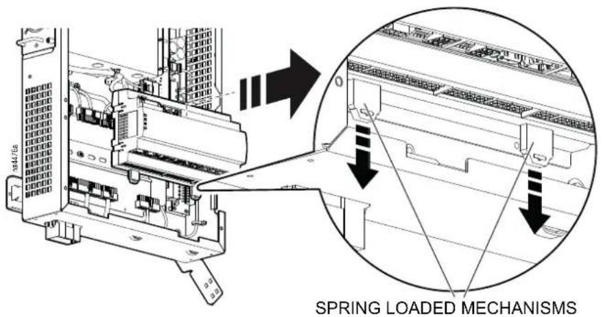
- There are two spring loaded mechanisms on the bottom of the Control Boa attaching it to the DIN rail. Using a flathead screwdriver, pull down on the spring loaded mechanisms until you hear them click and remove the controller.
Fan Assembly
▲WARNING
MOVING PARTS
If you are installing fans with power applied to the unit, the fans will begin operating as soon as the electrical connection is made. Take appropriate safety precautions to avoid moving parts and live electrical components.
Failure to follow these instructions can result in death, serious injury, or equipment damage.
⚠️ DANGER
HAZARD OF ELECTRIC SHOCK, EXPLOSION, OR ARC FLASH
Turn off all power supplying this equipment before working on the equipment. All electrical work must be performed by qualified personnel. Apply Lockout/Tagout procedures. Do not wear jewelry when working with electrical equipment.
Failure to follow these instructions will result in death or serious injury.
Removal
NOTE: Place the unit in standby before removing a fan assembly.
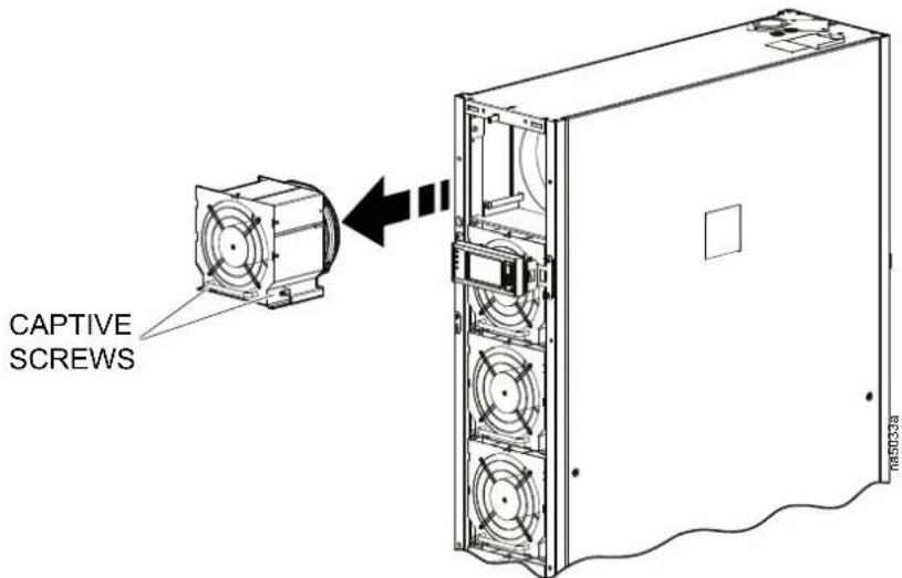
- Remove the front panel.
- Loosen the captive screws that secure the fan assembly to the mounting plan and remove the fan.
-
Install the new fan assembly. Verify that the fan assembly is properly secu to the mounting plate to ensure a good electrical connection.
-
Return the unit to service and check the fan operation.
Fan Power Supply
NOTICE
POWER SUPPLY CONFIGURATION
Two different power supplies are available for this unit. One type has holes in the metal faceplate in front of the fan. The other type has a wire guard over fan. Either type will work, but both power supplies must be the same, or improper operation will result.
Failure to follow these instructions can result in equipment damage.
Removal
-
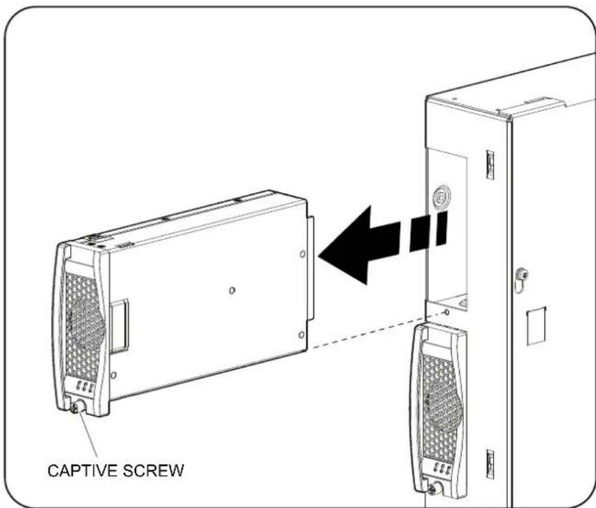
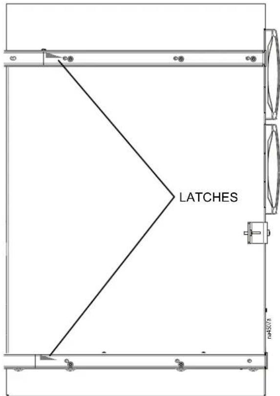
Release the latch securing the electrical box and carefully slide the electrical box out of the unit until the slider stops are engaged.
-
Loosen the two captive screws and remove the fan power supply.
-
Install the new fan power supply. Ensure that the power supply electrical connection is properly aligned and secure the fan power supply with the captive screws.
-
To push the electrical box back into the unit, release the top and bottom latches located on the two rails, until you hear a click.
Network Management Card
The Network Management Card is embedded in the cooling unit display interface and is non-serviceable.
To replace the Network Management Card, see Display Interface, page 35
After installation, verify the firmware version is current. See the Schneider Electric Software/Firmware Downloads Web page www.schneider-electric.com/download/ww/en.
Display Interface
NOTE: The display interface can be replaced without removing power from the unit.
Removal
- Remove the front panel.
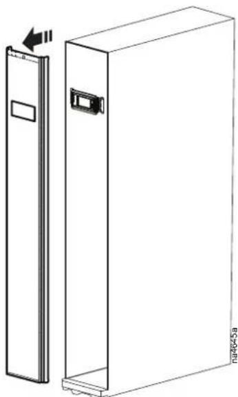
natural_image
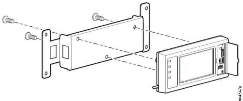
Technical line drawing of a rectangular cabinet with a side panel and mounting bracket (no text or symbols)- Remove the display mounting bracket screws.
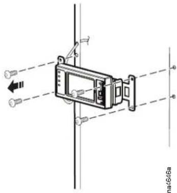
- Remove the screws holding the mounting bracket to the display.
natural_image
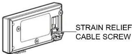
Technical line drawing of a mechanical assembly with mounting flanges and a control panel (no text or symbols)- Remove the cable strain relief screw and cable from the back of the display and disconnect the display cable.
Temperature Sensors
⚠️ DANGER
HAZARD OF ELECTRIC SHOCK, EXPLOSION, OR ARC FLASH
Turn off all power supplying this equipment before working on the equipment. All electrical work must be performed by qualified personnel. Apply Lockout/Tagout procedures. Do not wear jewelry when working with electrical equipment.
Failure to follow these instructions will result in death or serious injury.
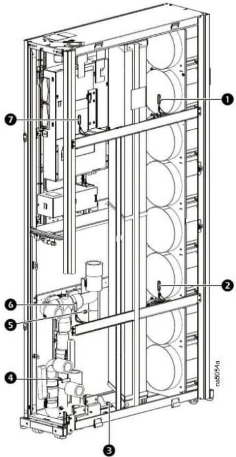
Item Description Item Description
| 1 | Supply air temperature sensor, top | 5 | Water out temperature sensor |
| 2 | Supply air temperature sensor, bottom | 6 | Return air temperature sensor, bottom |
| 3 | Coil entering water temperature sensor | 7 | Return air temperature sensor, top |
| 4 | Water in temperature sensor |
- Note which sensor needs to be replaced and its location in the unit.
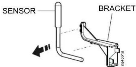
- Unclip the sensor from the bracket.
- Disconnect the sensor from the wiring harness.
- Reinstall the sensor.
Updating the Firmware
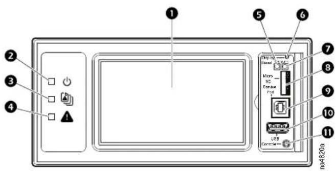
Item Description
4.3-in. touch-screen color display.
The cooling unit is powered when the LED is illuminated.
Unit firmware is updating when LED is blinking.
When this LED is illuminated, a new entry has been made to the event log.
4 Displays current alarm condition of unit.
5 Displays current network management card status.
6 Displays current network link status.
7 Resets the display microprocessor. This has no effect on the air conditioner controller.
8 Memory card expansion slot.
USB-B port used only by service personnel.
10 Supports firmware upgrades.
Connects the display to a local computer to configure initial network settings or access the command line interface (CLI).
Overview
Use a USB drive to transfer and upgrade the firmware files. The following provid an overview of steps required to update the firmware:
- Check the USB drive format.
- Create a firmware folder on the USB drive.
- Insert a USB drive in the USB-A port.
- Reset the display.
-
Wait until transfer is complete and remove the drive.
-
Download the firmware package and extract those files to the firmware folder.
-
Create an .rcf file for file transfer and place that file in the firmware folder.
Updating Procedure
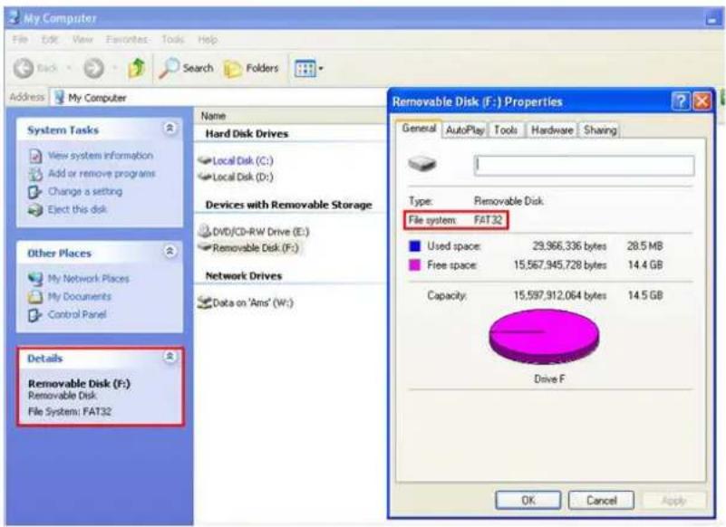
- Insert the USB drive into an available port on the PC and verify that the first system is formatted as FAT32. If the drive is not formatted, the USB drive must be formatted prior before continuing.
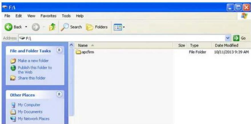
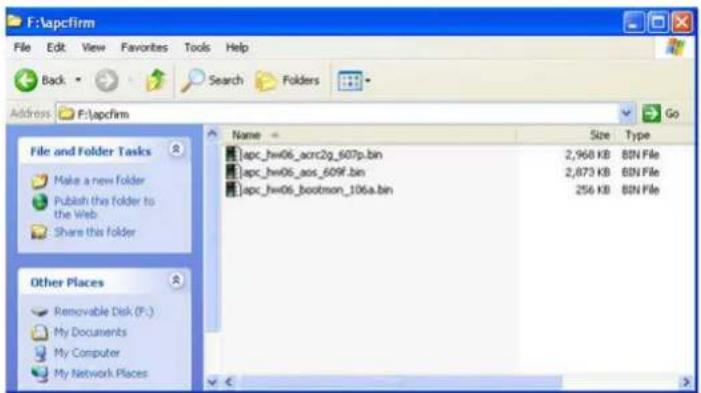
- Create a new folder named "apcfirm" on the USB drive.
-
Obtain the firmware files from the local support team or service website. Unzip and extract the firmware files to the "apcfirm" folder. Typically there a three .bin files for the application:
-
(_acrc2g_)
- operating system (_aos_)
- boot monitor (_bootmon_)
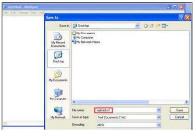
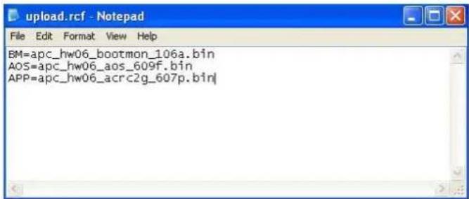
- Use a text editor, for example Notepad, to create a file named upload.rcf.
- Edit the file upload.rcf and write a text string for each firmware module that you want to transfer. For example, to transfer the files shown in Step 3 type the following exactly as shown below:
IMPORTANT: The firmware modules must be listed in the proper order in the upload.rcf file.
• BM (bootmon) must be listed first.
- AOS (operating system) must be listed second.
- APP (application) must be listed third.
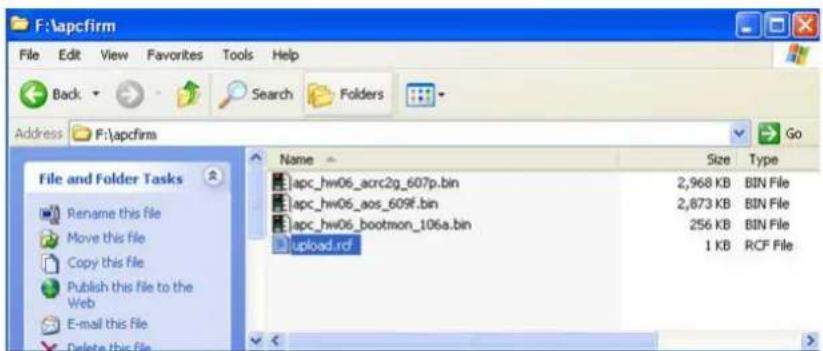
- Save the upload.rcf file in the "apcfirm" folder on the USB flash drive. The "apcfirm" folder should look similar to the following example:
-
Insert the USB drive into the display USB-A port. The display will detect that USB device has been connected.
-
Once acknowledged, press the Display Reset button. Wait approximately 2 - 3 minutes for the display to resume operation.
-
Return to the HOME screen menu.
NOTE: The touch screen will be disabled during the transfer process. There is no loss of cooling operation during the transfer process.
- Once the transfer is complete, remove the USB drive from the display. To perform the transfer on additional cooling units, insert the device in the USB-port and repeat Step 7.
Generating Service Passcodes
Generate service passcodes using the Cooling Tuner graphic user interface.
- Open the Cooling Tuner in the online or off-line mode.
- Select Maintenance > Service Authenticator.
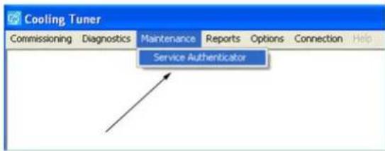
- Enter the Product Key in the box using upper case letters.
- Click Generate. The service code generates.
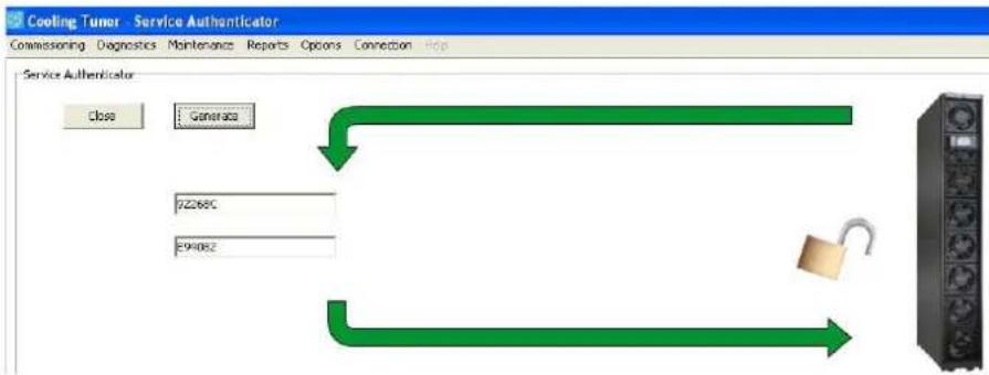
- Enter the service code exactly as shown on the cooling unit display interface
NOTE: After 48 hours, a new service code is necessary to access the service menu.
Dew Point Control Pump Programming
The dew point control pump is used to do the following:
- Maintain the chilled water coil temperature above point by recycling the warm water.
- Prevent condensation on the coil.
NOTE: Images below refer to the ACAC10031 Dew Point Control Pump kit (with Stratos model).
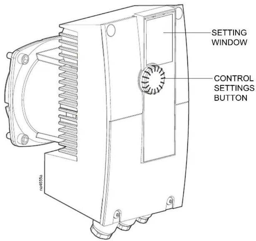
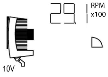
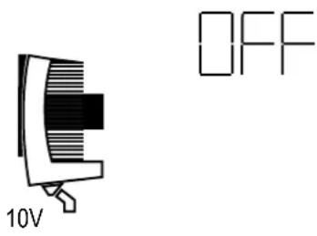
Correct Settings
Manual Control Mode
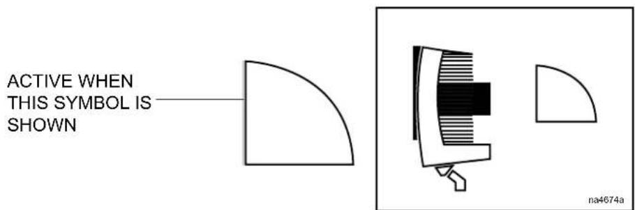
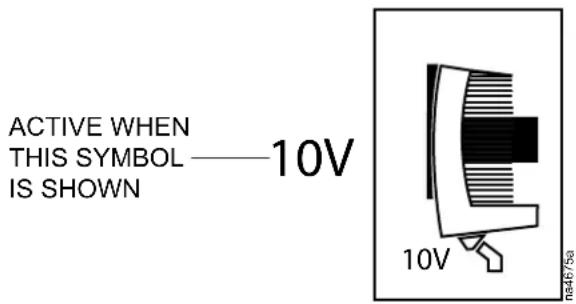
0-10V input active
Normal Operation
Pump command = ON
Pump command = OFF
084460a
n4460a
Check/change the settings
Changing text position
-
Push and hold the control button for two seconds to access the Level Operation Menu.
-
Do not hold the button longer than six seconds or you will enter the L 3 Option Menu.
- Do not alter the settings in the Level 3 Options Menu.
-
If no changes are made for 30 seconds, the display returns to Level 1 operating status.
-
While ON is flashing, rotate the control button left or right to change the t position to read horizontal or vertical. This setting will affect the orientation all other displayed settings.
- Press and release the control button to save the setting and go to step 2
Changing control mode
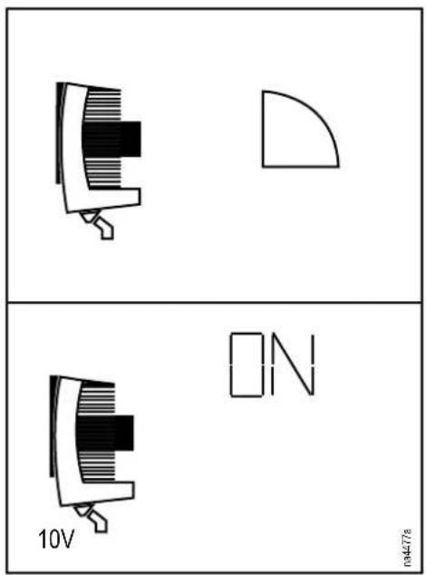
-
The control mode that is currently set is flashing.
-
Rotate the control button to select manual mode.
The symbol

- Press and release the control button to save the settings.
- Activate the 0-10V input.
- Rotate the control button to select ON.
- Press and release the control button to save the setting.
- The programming process is complete.
NOTE: Images below refer to the ACAC10061 Dew Point Control Pump kit (with Stratos MAXO model).
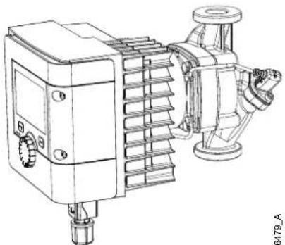
natural_image
Technical line drawing of a mechanical pump or motor assembly (no text or symbols visible)Stratos MAXO
0000766479_A
Refer to the ACAC10061 Installation Manual for pump setting information details on the ACAC10061 Dew Point Control Pump kit (with Stratos MAXO model).
Troubleshooting
See "Alarm messages and suggested actions" in the InRow RC Operation and Maintenance Manual.
Problem Possible Cause Corrective Action
| Cooling controller response is erratic or inoperative | Inlet temperature to the cooling unit is higher than the rated maximum temperatureCooling unit is not properly tunedInlet temperature to the cooling unit is higher than the rated maximum temperatureCooling unit is not properly tuned | Reduce the load or add additional cooling equipment.Contact Schneider Electric Customer Support.Reduce the load or add additional cooling equipment.Contact Schneider Electric Customer Support. |
| Fans fail to startPower supplies are not operating properlyFailed power supplyCooling unit inlet temperature is higher than rated maximum temperatureCooling unit shutdown due to an external commandSingle fan fails to start | Confirm that the power supplies are seated properly and fully engaged. This is indicated by a green LED.Confirm that the cooling unit is plugged in and is receiving power.Replace the power supply if the LED is red.Reduce the load or add additional cooling equipment.Temporarily remove the user input contact cable if it is connected.Confirm that the fan is seated properly and fully engaged.Replace the fan if it is faulty. | |
| Cooling unit cannot obtain setpointImproper placement of remote temperature sensorDirty filterDirty coilValve/actuator malfunctionIsolation valve is closed or is not open fullyApplication errorEntering water temperature is too highHeat load is too far awayCooling unit is not properly tuned | Verify that the remote temperature sensor is properly located in the cold aisle.Clean the filter.Clean the coil.Fully open the valve.Fully open the valve.Contact Schneider Electric Customer Support.Verify that the temperature of the cooling unit water supply is within the specified range.Place the cooling unit closer to the heat load.Contact Schneider Electric Customer Support. | |
| Water carryoverImproper fan speed selectedInlet water temperature is too lowRoom humidity is too high | Select the next highest fan speed setting. For example, change the fan speed setting from Low to Med/Low.Verify that the temperature of the inlet | |
| Dirty coilDirty filter | water is within the specified range.Adjust setpoint on dehumidifying equipment.Add additional dehumidifying equipment.Clean the coil.Clean the air filter. | |
| Cooling controller response is erratic or inoperative | Inlet temperature to the cooling unit is higher than the rated maximum temperatureCooling unit is not properly tuned | Reduce the load or add additional cooling equipment.Contact Schneider Electric Customer Support. |
| Cooling unit fan sound is louder than expected | Improper fan speed selectedIncorrect placement of remote temperature sensor | Select a lower fan speed.Verify that the remote temperature sensor is properly located in the cold aisle. |
| Temperature control not tight enough | Improper placement of remote temperature sensorImproper PID tuning | Verify that the remote temperature sensor is properly located in the cold aisle.Contact Schneider Electric Customer Support. |
| Water on outside of cooling unit | Condensate drain hose is not connected or not properly routed outside the Cooling UnitLeak in piping systemCooling unit not leveled properlyDamaged piping insulation | Verify that the condensate drain hose is properly connected to the pump and properly routed outside of the cooling unit.Verify that the condensate drain line does not exceed 12 feet lift and 30 feet horizontal run.Locate and repair the leak.Adjust the leveling feet of the cooling unit.Identify damaged area and repair the insulation. |
| Water valve not responsive | Actuator not connected properlyActuator and shaft not rotating together | Verify that the actuator is connected properly.Tighten the linkage screw on the actuator shaft. |
| Display interface not operational but cooling unit operates | Display interface not connected properly | Verify that the display interface cable is connected properly. |
| Incorrect air filter differential pressure reading | False filter clogsVerify that the ends of the clear plastic air tubes are not obstructed.Verify that the clear plastic air tubes are connected to the controller.Verify that the clear plastic air tubes are not pinched. | |
| Alarms do not show up on monitoring equipment (Form C) | External monitoring equipment is not receiving power or is not functioning properly | Confirm that power, if required, is being supplied to the external equipment.If the cooling unit is providing power (+12 V or +24 V) to the external equipment, verify that theexternal equipment is <50 mA.· Test the external equipment by bypassing the Form C. |
| Cooling unit does not shut down when using the input contact | · Drive voltage · Verify that there is drive voltage entering the input of the cooling unit. You may use the available +12 V or +24 V. You must then also use the ground. | |
| Cooling controller response is erratic or inoperative | · Inlet temperature to the cooling unit is higher than the rated maximum temperature· Cooling unit is not properly tuned | · Reduce the load or add additional cooling equipment.· Contact Schneider Electric Customer Support. |
| No communication with building management system (BMS) port | · Improper connection· Wrong baud rate· Wrong ID | · Confirm that the Cooling Unit is connected to the BMS port and not to the Control port.· Verify that the wire polarity is correct.· Using a DC voltmeter, test the signal with no transmissions in progress: expect Pin 2 to be greater than Pin 1 by at least 200 mV. Measure the cooling unit with the cable disconnected, and then measure it again with the cable connected. If the signal is less than 200 mV, the cooling unit may be reverse-wired.· Make sure that every cooling unit has either two sets of wires in its connector OR one set of wires and a terminating resistor of 100 to 120 ohms.· Verify the baud rate is correct.· Verify the ID is correct. |
| Cooling units are not communicating with each other | · A-Link CAN · Verify that the A-Link port of every cooling unit has either two cables or one cable and a terminator.· Confirm that the A-Link cables are connected to the A-Link ports and that a network cable is connected to the network port. | |
Appendix
InRow Touchscreen Diagrams
All Menus
flowchart
Air filter system flowchart detailing components from high-temperature supply to active alarm, including configuration, group, service, and status branches.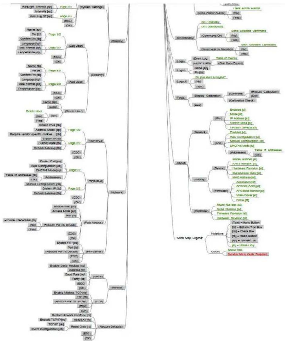
flowchart
graph TD
    A["Handbag: timanor [p1"] --> B["Intensity [a2"]]
    A --> C["Auto Luy Of [a3"]]
    A --> D["Name [a4"]]
    D --> E["Pin [b5"]]
    D --> F["Confirm Pin [b6"]]
    D --> G["Language [a7"]]
    D --> H["Data format [c0"]]
    D --> I["Temperature [c1"]]
    A --> J["Name [a8"]]
    J --> K["Pin [b6"]]
    J --> L["Confirm Pin [b7"]]
    J --> M["Language [a9"]]
    J --> N["Data format [c1"]]
    A --> O["Page 1/2"]
    O --> P["Add User"]
    P --> Q["Address"]
    P --> R["Page 2/2"]
    R --> S["Address"]
    R --> T["Page 2/2"]
    T --> U["Address"]
    U --> V["Address"]
    A --> W["Name [a9"]]
    W --> X["Origin [b7"]]
    W --> Y["Confirm Pin [b8"]]
    W --> Z["Language [a9"]]
    W --> AA["Data format [c1"]]
    W --> AB["Temperature [c2"]]
    A --> AC["Name [a9"]]
    AC --> AD["Origin [b7"]]
    AC --> AE["Confirm Pin [b8"]]
    AC --> AF["Language [a9"]]
    AC --> AG["Data format [c1"]]
    AC --> AH["Temperature [c3"]]
    A --> AI["Page 1/2"]
    AI --> AJ["Add User"]
    AJ --> AK["Address"]
    AJ --> AL["Address"]
    AJ --> AM["Address"]
    AJ --> AN["Address"]
    AJ --> AO["Address"]
    AJ --> AP["Address"]
    AJ --> AQ["Address"]
    AJ --> AR["Address"]
    AJ --> AS["Address"]
    AJ --> AT["Address"]
    AJ --> AU["Address"]
    AJ --> AV["Address"]
    AJ --> AW["Address"]
    AJ --> AX["Address"]
    AJ --> AY["Address"]
    AJ --> AZ["Address"]
    AJ --> BA["Address"]
    AJ --> BB["Address"]
    AJ --> BC["Address"]
    AJ --> BD["Address"]
    AJ --> BE["Address"]
    AJ --> BF["Address"]
    AJ --> BG["Address"]
    AJ --> BH["Address"]
    AJ --> BI["Address"]
    AJ --> BJ["Address"]
    AJ --> BK["Address"]
    AJ --> BL["Address"]
    AJ --> BM["Address"]
    AJ --> BN["Address"]
    AJ --> BO["Address"]
    AJ --> BP["Address"]
    AJ --> BQ["Address"]
    AJ --> BR["Address"]
    AJ --> BS["Address"]
    AJ --> BT["Address"]
    AJ --> BU["Address"]
    AJ --> BV["Address"]
    AJ --> BW["Address"]
    AJ --> BX["Address"]
    AJ --> BY["Address"]
    AJ --> BZ["Address"]
    AJ --> CA["Address"]
    AJ --> CB["Address"]
    AJ --> CC["Address"]
    AJ --> CD["Address"]
    AJ --> CE["Address"]
    AJ --> CF["Address"]
    AJ --> CG["Address"]
    AJ --> CH["Address"]
    AJ --> CI["Address"]
    AJ --> CJ["Address"]
    AJ --> CK["Address"]
    AJ --> CL["Address"]
    AJ --> CM["Address"]
    AJ --> CN["Address"]
    AJ --> CO["Address"]
    AJ --> CP["Address"]
    AJ --> CQ["Address"]
    AJ --> CR["Address"]
    AJ --> CS["Address"]
    AJ --> CT["Address"]
    AJ --> CU["Address"]
    AJ --> CV["Address"]
    AJ --> CW["Address"]
    AJ --> CX["Address"]
    AJ --> CY["Address"]
    AJ --> CZ["Address"]
    AJ --> DA["Address"]
    AJ --> DB["Address"]
    AJ --> DC["Address"]
    AJ --> DD["Address"]
    AJ --> DEA["Address"]
    AJ --> DF["Address"]
    AJ --> DG["Address"]
    AJ --> DH["Address"]
    AJ --> DIA["Address"]
    AJ --> DJA["Address"]
    AJ --> DKA["Address"]
    AJ --> DLA["Address"]
    AJ --> DVA["Address"]
    AJ --> DWA["Address"]
The following graphics provide enlarged views of InRow Touchscreen navigation.
Home Menu
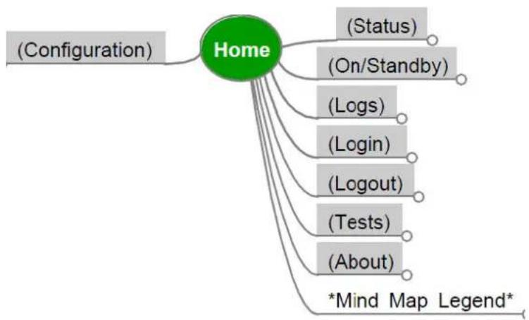
flowchart
graph TD
    A["Home"] --> B["(Configuration)"]
    A --> C["(Status)"]
    A --> D["(On/Standby)"]
    A --> E["(Logs)"]
    A --> F["(Login)"]
    A --> G["(Logout)"]
    A --> H["(Tests)"]
    A --> I["(About)"]
    A --> J["*Mind Map Legend*"]
Unit Threshold Configuration
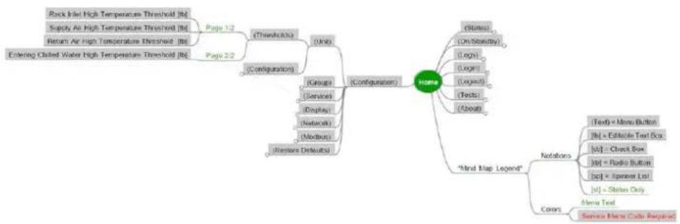
flowchart
graph TD
    A["Rock Inlet High Temperature Threshold"] --> B["Page 1-2"]
    C["Supply Air High Temperature Threshold"] --> D["Page 2-2"]
    E["Return Air High Temperature Threshold"] --> F["Page 2-2"]
    G["Entering Closed Water High Temperature Threshold"] --> H["Configuration"]
    I["Rock Inlet High Temperature Threshold"] --> J["Page 1-2"]
    K["Supply Air High Temperature Threshold"] --> L["Page 2-2"]
    M["Existing Closed Water High Temperature Threshold"] --> N["Configuration"]
    O["Rock Inlet High Temperature Threshold"] --> P["Page 1-2"]
    Q["Supply Air High Temperature Threshold"] --> R["Page 2-2"]
    S["Existing Closed Water High Temperature Threshold"] --> T["Configuration"]
    U["Rock Inlet High Temperature Threshold"] --> V["Page 1-2"]
    W["Supply Air High Temperature Threshold"] --> X["Page 2-2"]
    Y["Existing Closed Water High Temperature Threshold"] --> Z["Configuration"]
    AA["Rock Inlet High Temperature Threshold"] --> AB["Page 1-2"]
    AC["Supply Air High Temperature Threshold"] --> AD["Page 2-2"]
    AE["Existing Closed Water High Temperature Threshold"] --> AF["Configuration"]
    AG["Rock Inlet High Temperature Threshold"] --> AH["Page 1-2"]
    AI["Supply Air High Temperature Threshold"] --> AJ["Page 2-2"]
    AK["Existing Closed Water High Temperature Threshold"] --> AL["Configuration"]
    AM["Rock Inlet High Temperature Threshold"] --> AN["Page 1-2"]
    AO["Supply Air High Temperature Threshold"] --> AP["Page 2-2"]
    AQ["Existing Closed Water High Temperature Threshold"] --> AR["Configuration"]
    AS["Rock Inlet High Temperature Threshold"] --> AT["Page 1-2"]
    AU["Supply Air High Temperature Threshold"] --> AV["Page 2-2"]
    AW["Existing Closed Water High Temperature Threshold"] --> AX["Configuration"]
    AY["Rock Inlet High Temperature Threshold"] --> AZ["Page 1-2"]
    BA["Supply Air High Temperature Threshold"] --> BB["Page 2-2"]
    BC["Existing Closed Water High Temperature Threshold"] --> BD["Configuration"]
    BE["Rock Inlet High Temperature Threshold"] --> BF["Page 1-2"]
    BG["Supply Air High Temperature Threshold"] --> BH["Page 2-2"]
    BI["Existing Closed Water High Temperature Threshold"] --> BJ["Configuration"]
    BK["Rock Inlet High Temperature Threshold"] --> BL["Page 1-2"]
    BM["Supply Air High Temperature Threshold"] --> BN["Page 2-2"]
    BO["Existing Closed Water High Temperature Threshold"] --> BP["Configuration"]
    BQ["Rock Inlet High Temperature Threshold"] --> BR["Page 1-2"]
    BS["Supply Air High Temperature Threshold"] --> BT["Page 2-2"]
    BU["Existing Closed Water High Temperature Threshold"] --> BV["Configuration"]
    BW["Rock Inlet High Temperature Threshold"] --> BX["Page 1-2"]
    BY["Supply Air High Temperature Threshold"] --> BZ["Page 2-2"]
    CA["Existing Closed Water High Temperature Threshold"] --> CB["Configuration"]
    CC["Rock Inlet High Temperature Threshold"] --> CD["Page 1-2"]
    CE["Supply Air High Temperature Threshold"] --> CF["Page 2-2"]
    CG["Existing Closed Water High Temperature Threshold"] --> DH["Configuration"]
    DI["Mood Map Legend"] --> DJ["Mood Map Legend"]
    DJ --> DJ1["Notations"]
    DJ1 --> DJ1a["Text = Menu Button"]
    DJ1a --> DJ1a1["Itb = Editable Text Box"]
    DJ1a --> DJ1a2["LcI = Check Box"]
    DJ1a --> DJ1a3["Jcp = Radio Button"]
    DJ1a --> DJ1a4["Jcp = Speaker List"]
    DJ1a --> DJ1a5["LdI = Station Only"]
    DJ --> DJ2["Coors"]
    DJ2 --> DJ2a["Menu Text"]
    DJ2 --> DJ2b["Service Menu Code Required"]
Unit Configuration
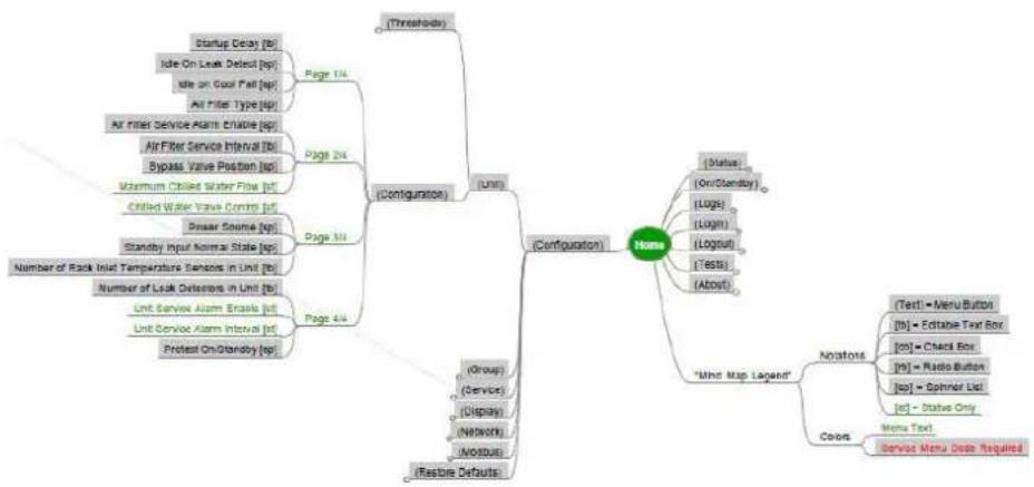
flowchart
graph TD
    A["(Threshold)"] --> B["(Configuration)"]
    B --> C["Page 1/4"]
    B --> D["Page 2/4"]
    B --> E["Page 3/4"]
    B --> F["Page 4/4"]
    B --> G["Configuration"]
    G --> H["Node"]
    H --> I["Status: [On/Standby"]]
    H --> J["Logus: (Logs)"]
    H --> K["Login"] (Logout)
[Test] (About)]
    G --> L["Mino Map Legend"]
    L --> M["Annotations"]
    M --> N["Text1 = Menu Button"]
    M --> O["[b0"] = Editable Text Box]
    M --> P["[o0"] = Check Box]
    M --> Q["[o5"] = Radio Button]
    M --> R["[o7"] = Spinner List]
    M --> S["[o7"] - Status Only]
    L --> T["Coors: Menu Text, Service Menu Setup Required"]
    B --> U["(Group) (Service) (Display) (Network) (NOODUE)"]
    B --> V["(Restone Defaults)"]
Group Configuration
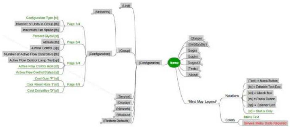
flowchart
graph TD
    A["Configuration"] --> B["(Serborths)"]
    A --> C["(Group)"]
    A --> D["(Restore Defaults)"]
    A --> E["(Service)"]
    A --> F["(Modbus)"]
    A --> G["(Network)"]
    A --> H["(Service"]
    H --> I["(Readout"]
    A --> J["(Number of Units in Group [B"]]
    A --> K["Maximum Fan Speed [B"]]
    A --> L["Perscent Glycol [B"]]
    A --> M["Altitude [B"]]
    A --> N["Artifour Control [B"]]
    A --> O["Number of Active Flow Controllers [B"]]
    A --> P["Active Flow Control Lamp TestExp"]
    A --> Q["Active Flow Control Rides [B"]]
    A --> R["Active Flow Control Status [B"]]
    A --> S["Cool Gain T* [B"]]
    A --> T["Cool Riser Rate T* [B"]]
    A --> U["Cool Derivative T* [B"]]
    A --> V["(Configuration)"]
    V --> W["(Status"]
    W --> X["(OnStandby)"]
    W --> Y["(Login"]
    W --> Z["(Logout"]
    W --> AA["(Tests"]
    W --> AB["(About)"]
    V --> AC["Mind Map Legend"]
    AC --> AD["Notations"]
    AD --> AE["(Text"] = Menu Button]
    AD --> AF["(Jo"] = Editable Text Box]
    AD --> AG["(Id3"] = Check Box]
    AD --> AH["(Jo"] = Radio Button]
    AD --> AI["(sp"] = Spinner List]
    AD --> AJ["(Jo"] = Status Only]
    AC --> AK["Colors"]
    AK --> AL["Menu Text"]
    AK --> AM["Service Menu Code Required"]
Group Setpoints
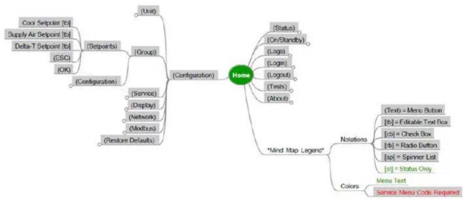
flowchart
graph TD
    A["Configuration"] --> B["(Unit)"]
    A --> C["(Group)"]
    A --> D["(Service)"]
    A --> E["(Display)"]
    A --> F["(Network)"]
    A --> G["(Modbus)"]
    A --> H["(Restore Defaults)"]
    A --> I["Home"]
    I --> J["(Status)"]
    I --> K["(On/Standby)"]
    I --> L["(Logs)"]
    I --> M["(Login)"]
    I --> N["(Logout)"]
    I --> O["(Tests)"]
    I --> P["(About)"]
    I --> Q["*Mind Map Legend*"]
    Q --> R["(Text) = Menu Button"]
    Q --> S["[lb"] = Editable Text Box]
    Q --> T["[cb"] = Check Box]
    Q --> U["[rb"] = Radio Button]
    Q --> V["[sp"] = Spinner List]
    Q --> W["[st"] = Status Only]
    Q --> X["Colors"]
    X --> Y["Menu Text"]
    X --> Z["Service Menu Code Required"]
Display Preferences
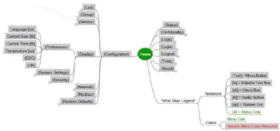
flowchart
graph TD
    A["Home"] --> B["(Configuration)"]
    A --> C["Status"]
    A --> D["Mind Map Legend"]
    D --> E["Notations"]
    D --> F["Colors"]
    E --> G["(Text) = Menu Button"]
    E --> H["[tb"] = Editable Text Box]
    E --> I["[cb"] = Check Box]
    E --> J["[rb"] = Radio Button]
    E --> K["[sp"] = Spinner List]
    E --> L["[st"] = Status Only]
    F --> M["Menu Text"]
    F --> N["Service Menu Code Required"]
    A --> O["(Unit"]
    O --> P["(Group)<br>    O --> Q[(Service)"]
    A --> R["(Preferences"]
    R --> S["(System Settings"]
    R --> T["(Security)"]
    A --> U["(Network)<br>    U --> V[(Modbus)"]
    A --> W["(Restore Defaults)"]
    A --> X["(ESC)<br>    X --> Y[(OK)"]
Service Code Configuration
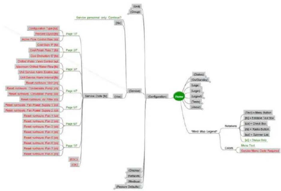
flowchart
graph TD
    A["Service personal only: Continuous?"] --> B["Configuration"]
    B --> C["Unit"]
    B --> D["Group"]
    B --> E["(Yes)"]
    B --> F["(No)"]
    E --> G["Configuration Type (bp)"]
    G --> H["Percolat Glycer (B)"]
    H --> I["Active Flow Control Rate (Rc) [60"]]
    I --> J["Cool Gain P* (Bc)"]
    J --> K["Cool Power Rate T* (Bc)"]
    K --> L["Cool Dehalation D* (Bc)"]
    L --> M["Chilled Water Valve Control Set"]
    M --> N["Maximum Chilled Water Pulse (Bc)"]
    N --> O["Unit Service Alarm Enable (Bc)"]
    O --> P["Unit Service Alarm Interval (Bc)"]
    P --> Q["Reset returnout: Unit (ch)"]
    Q --> R["Reset returnout: Condensate Pump (ch)"]
    R --> S["Reset returnout: Circulation Pump (ch)"]
    S --> T["Reset returnout: Air Filter (cc)"]
    T --> U["Reset returnout: Fan Power Supply 1 (cal)"]
    U --> V["Reset returnout: Fan Power Supply 2 (cal)"]
    V --> W["Reset returnout: Fan 1 (cal)"]
    W --> X["Reset returnout: Fan 2 (ch)"]
    X --> Y["Reset returnout: Fan 3 (ch)"]
    Y --> Z["Reset returnout: Fan 4 (ch)"]
    Z --> AA["Reset returnout: Fan 5 (ch)"]
    AA --> AB["Reset returnout: Fan 8 (ch)"]
    AB --> AC["Reset returnout: Fan 7 (ch)"]
    AC --> AD["Reset returnout: Fan 8 (ch)"]
    AD --> AE["(ESC)"]
    AE --> AF["(Ch)"]

    B --> AG["(Status)"]
    AG --> AH["(On/Glandby)"]
    AH --> AI["(Loga)"]
    AI --> AJ["(Login)"]
    AJ --> AK["(Logout)"]
    AK --> AL["(Techs)"]
    AL --> AM["(About)"]

    B --> AN["'Mind Map Legend'"]
    AN --> AO["Notebook"]
    AN --> AP["Colors"]

    B --> AQ["(Tev"] = Menu Button]
    AQ --> AR["(It"] = Elective Text Box]
    AR --> AS["(Cq"] = Chuck Bus]
    AS --> AT["(It"] = Radio Button]
    AT --> AU["(Scl"] = Spinner List]
    AU --> AV["(It"] = Status Only]

    B --> AW["Menu Text"]
    AW --> AX["Service Menu Code Required"]

    B --> AY["(Display"]
    AY --> AZ["Network"]
    AY --> BA["Modus"]

    B --> BB["(Feature Defaults)"]
System Settings Display Configuration
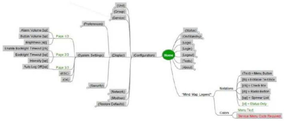
flowchart
graph TD
    A["Home"] --> B["(Preferences)"]
    A --> C["(Display)"]
    A --> D["(Configuration)"]
    B --> E["(Form)"]
    B --> F["(Group)"]
    B --> G["(Service)"]
    C --> H["(Security)"]
    C --> I["(Network)"]
    C --> J["(Modbus)"]
    C --> K["(Restore Defaults)"]
    D --> L["(Status)"]
    D --> M["(On/Standby)"]
    D --> N["(Logs)"]
    D --> O["(Login)"]
    D --> P["(Logout)"]
    D --> Q["(Tests)"]
    D --> R["(About)"]
    A --> S["Mind Map Legend"]
    S --> T["(Text) = Menu Button"]
    S --> U["[t0"] = Estonia Text Box]
    S --> V["[t0"] = Check Box]
    S --> W["[t0"] = Radio Button]
    S --> X["[sp"] = Spinner List]
    S --> Y["[n"] = Status Only]
    A --> Z["Colors"]
    Z --> AA["Menu Test"]
    Z --> AB["Service Menu Code Required"]
Security Display Configuration
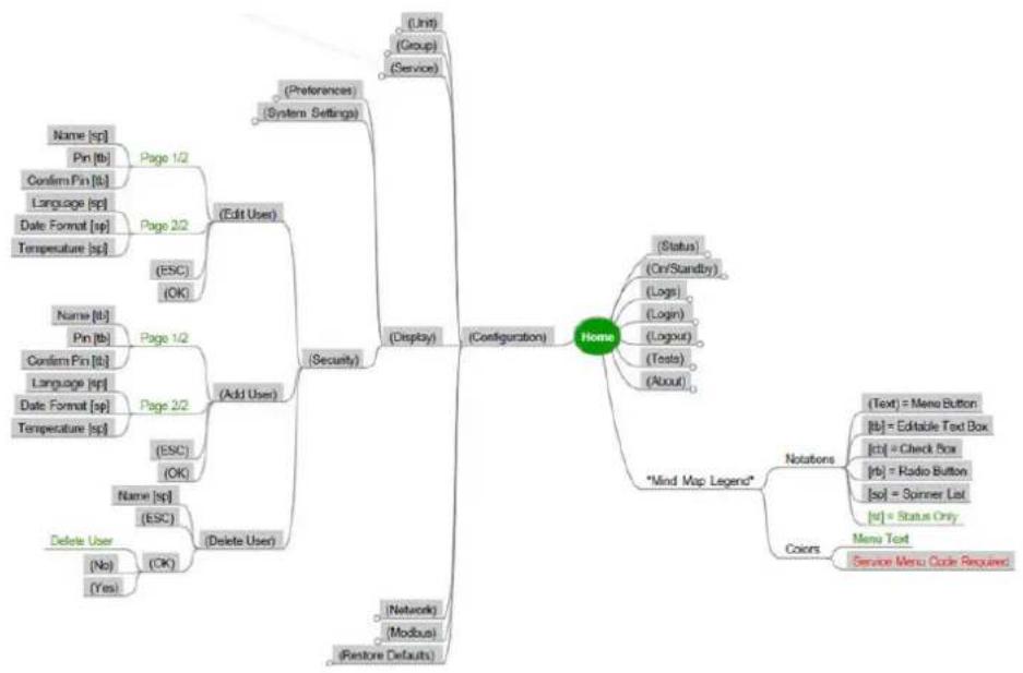
flowchart
graph TD
    A["Home"] --> B["(Configuration)"]
    A --> C["(Display)"]
    A --> D["(Security)"]
    A --> E["(Edit User)"]
    A --> F["(Release User)"]
    A --> G["(Restore Defaults)"]

    B --> H["(Unit"]
    B --> I["(Group)<br>    B --> J[(Service)"]

    C --> K["(Name: [sp"]]
    C --> L["Pin: [tb"]]
    C --> M["Confirm Pin: [tb"]]
    C --> N["Language: [sp"]]
    C --> O["Date Format: [sp"]]
    C --> P["Temperature: [sp"]]

    D --> Q["(ESC"]
    D --> R["(OK)"]

    E --> S["(Status)<br>    (On/Standby)"]
    E --> T["(Logs"]
    E --> U["(Login)"]
    E --> V["(Logout)"]
    E --> W["(Tests)"]
    E --> X["(About)"]

    F --> Y["Note"]
    F --> Z["Mind Map Legend"]

    Z --> AA["Notations"]
    Z --> AB["Colors"]

    AA --> AC["(Text"] = Menu Button]
    AA --> AD["[tb"] = Editable Text Box]
    AA --> AE["[ct"] = Check Box]
    AA --> AF["[rb"] = Radio Button]
    AA --> AG["sol = Spinner List"]
    AA --> AH["rd"] = Status Only]

    AB --> AI["Menu Text"]
    AB --> AJ["Service Menu Code Required"]
TCP-IPv4 Network Configuration
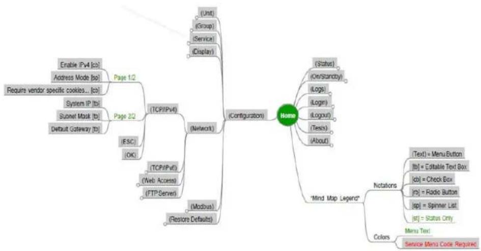
flowchart
graph TD
    A["Home"] --> B["(Configuration)"]
    A --> C["Mind Map Legend"]
    C --> D["Notations"]
    C --> E["Colors"]
    D --> F["(Text) = Menu Button"]
    D --> G["(b1) = Editable Text Box"]
    D --> H["(cb) = Check Box"]
    D --> I["(rb) = Radio Button"]
    D --> J["(sp) = Spinner List"]
    D --> K["(sf) = Status Only"]
    E --> L["Menu Text"]
    E --> M["Service Menu Code Required"]
    A --> N["(Unit)<br>(Group)<br>(Service)<br>(Display)"]
    A --> O["(ESC)<br>(OK)"]
    A --> P["(TCP/IPv4)<br>(Network)"]
    A --> Q["(Modbus)<br>(Restore Defaults)"]
    A --> R["(System IP (tbi)<br>Subnet Mask (tb)<br>Default Gateway (tb)"]
    A --> S["Enable IPv4 (cb)<br>Address Mode (sp)<br>Require vendor specific cookies... (cb)"]
TCP-v6 Network Configuration
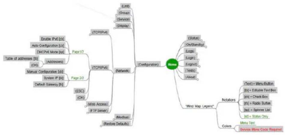
flowchart
graph TD
    A["Table of addresses [b"]] --> B["Enable IPv6 [cb"]]
    A --> C["Auto Configuration [cb"]]
    A --> D["DHCPv6 Mode [bp"]]
    A --> E["(OK)"]
    A --> F["Adresses"]
    A --> G["Manual Configuration [cb"]]
    A --> H["System IP [pb"]]
    A --> I["Default Gateway [tb"]]
    A --> J["(TCP/IPv4)"]
    J --> K["(Network)"]
    K --> L["(TCP/IPv6)"]
    L --> M["(ESC)"]
    M --> N["(OK)"]
    L --> O["(Web Access)"]
    O --> P["(FTP Server)"]
    L --> Q["(Modbus)"]
    Q --> R["(Restore Defaults)"]
    R --> S["(Modbus)"]
    S --> T["(House)"]
    T --> U["(Status)"]
    U --> V["(On/Standby)"]
    U --> W["(Logi)"]
    U --> X["(Login)"]
    U --> Y["(Tests)"]
    U --> Z["(About)"]
    T --> AA["Minds Map Legend"]
    AA --> AB["Notations"]
    AB --> AC["(Text"] = Menu Button]
    AB --> AD["[b"] = Editable Text Box]
    AB --> AE["[cts"] = Check Box]
    AB --> AF["[rb"] = Radio Button]
    AB --> AG["[bp"] = Spinner List]
    AB --> AH["Id"] = States Only]
    AA --> AI["Colors"]
    AI --> AJ["Menu Tec"]
    AI --> AK["Service Menu Code Required"]
Web Access Network Configuration
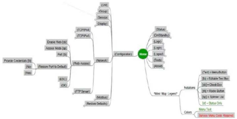
flowchart
graph TD
    A["Configuration"] --> B["Home"]
    B --> C["(Status)"]
    C --> D["(On/Standby)"]
    C --> E["(Logs)"]
    C --> F["(Logout)"]
    C --> G["(Tests)"]
    C --> H["(About)"]
    B --> I["Modbus"]
    I --> J["(Restore Defaults)"]
    B --> K["(Network)"]
    K --> L["(TCP/IPV)"]
    K --> M["(TCP/IPVI)"]
    K --> N["(Web Access)"]
    K --> O["(FTP Server)"]
    K --> P["(ESC)"]
    K --> Q["(OK)"]
    B --> R["Notations"]
    R --> S["(Text = Menu Button"]
    R --> T["(b1 = Editable Text Bus"]
    R --> U["(cb1 = Check Box"]
    R --> V["(rb2 = Radie Button"]
    R --> W["(sp1 = Spinner List"]
    R --> X["st1 = Status Only"]
    B --> Y["Colors"]
    Y --> Z["Menu Text"]
    Y --> AA["Service Menu Code Required"]
FTP Network Server Configuration
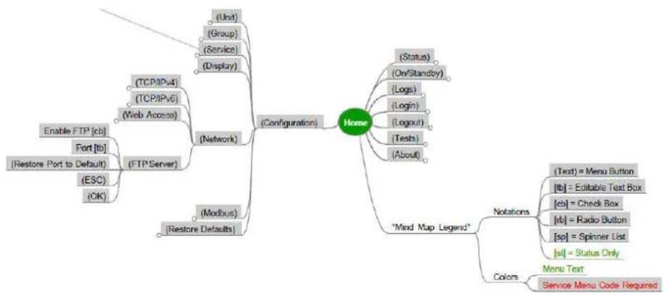
flowchart
graph TD
    A["Configuration"] --> B["(Unit)"]
    A --> C["(Group)"]
    A --> D["(Service)"]
    A --> E["(Display)"]
    A --> F["(Network)"]
    A --> G["(Modbus)"]
    A --> H["(Restore Defaults)"]
    A --> I["Enable FTP [cb"]]
    A --> J["Port [tb"]]
    A --> K["(Restore Port to Default)"]
    A --> L["(ESC)"]
    A --> M["(OK)"]
    A --> N["(*Status) (On/Standby)"]
    A --> O["(*Status) (Logs)"]
    A --> P["(*Status) (Login)"]
    A --> Q["(*Status) (Tests)"]
    A --> R["(*Status) (About)"]
    A --> S["Mind Map Legend"]
    S --> T["Notations"]
    T --> U["(Text) = Menu Button"]
    T --> V["[tb"] = Editable Text Box]
    T --> W["[cb"] = Check Box]
    T --> X["[rb"] = Radio Button]
    T --> Y["[sp"] = Spinner List]
    T --> Z["[sl"] = Status Only]
    S --> AA["Colors"]
    AA --> AB["Menu Text"]
    AA --> AC["Service Menu Code Required"]
Serial Modbus Configuration
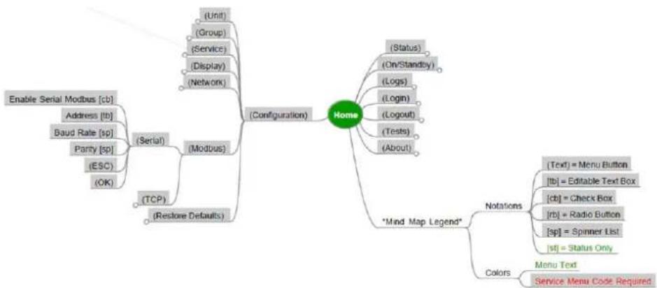
flowchart
graph TD
    A["Home"] --> B["(Configuration)"]
    A --> C["(*Mind Map Legend*)"]
    A --> D["(Unit)"]
    A --> E["(Group)"]
    A --> F["(Service)"]
    A --> G["(Display)"]
    A --> H["(Network)"]
    A --> I["(Modbus)"]
    A --> J["(Modbus)"]
    A --> K["(TCP)"]
    A --> L["(Restore Defaults)"]
    A --> M["(Enable Serial Modbus [cb"], Address["lb"], Baud_Rate["sp"], Parry["sp"], (ESC), (OK).]
    A --> N["(Serial)"]
    A --> O["(Logout)"]
    A --> P["(Tests)"]
    A --> Q["(About)"]
    A --> R["(Status)"]
    R --> S["(On/Standby)"]
    R --> T["(Logs)"]
    R --> U["(Login)"]
    R --> V["(Logout)"]
    R --> W["(Tests)"]
    R --> X["(About)"]
    A --> Y["Notations"]
    Y --> Z["(Text"] = Menu Button]
    Y --> AA["[lb"] = Editable Text Box]
    Y --> AB["[cb"] = Check Box]
    Y --> AC["[rb"] = Radio Button]
    Y --> AD["[sp"] = Spinner List]
    Y --> AE["[st"] = Status Only]
    A --> AF["Colors"]
    AF --> AG["Menu Text"]
    AF --> AH["Service Menu Code Required"]
Modbus Configuration
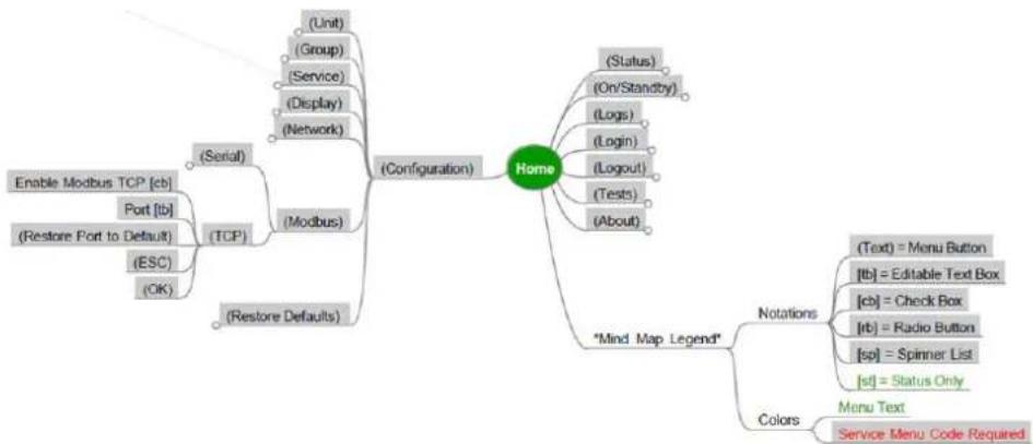
flowchart
graph TD
    A["Configuration"] --> B["(Serial)"]
    A --> C["(Modbus)"]
    A --> D["(Restore Defaults)"]
    A --> E["Home"]
    E --> F["(Unit)"]
    E --> G["(Group)"]
    E --> H["(Service)"]
    E --> I["(Display)"]
    E --> J["(Network)"]
    E --> K["(ESC)"]
    E --> L["(OK)"]
    E --> M["(Restore Port to Default)"]
    E --> N["(Logs)"]
    E --> O["(Login)"]
    E --> P["(Tests)"]
    E --> Q["(About)"]
    E --> R["Status"]
    R --> S["(On/Standby)"]
    R --> T["(Logs)"]
    R --> U["(Logout)"]
    R --> V["(Tests)"]
    R --> W["(About)"]
    E --> X["Mind Map Legend"]
    X --> Y["Notations"]
    Y --> Z["(Text) = Menu Button"]
    Y --> AA["[tb"] = Editable Text Box]
    Y --> AB["[cb"] = Check Box]
    Y --> AC["[rb"] = Radio Button]
    Y --> AD["[sp"] = Spinner List]
    Y --> AE["[st"] = Status Only]
    X --> AF["Colors"]
    AF --> AG["Menu Text"]
    AF --> AH["Service Menu Code Required"]
Restore Defaults Configuration
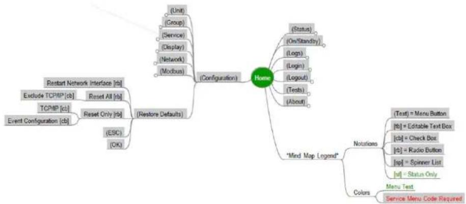
flowchart
graph TD
    A["Home"] --> B["(Configuration)"]
    A --> C["Mind Map Legend"]
    A --> D[""Event Configuration (cb)"]
    A --> E[""Restart Network Interface (rb)"]
    A --> F[""Reset All (rb)"]
    A --> G[""Reset Only (rb)"]
    A --> H["(ESC)"]
    A --> I["(OK)"]
    A --> J["(Unit)"]
    J --> K["(Group)"]
    J --> L["(Service)"]
    J --> M["(Display)"]
    J --> N["(Network)"]
    J --> O["(Modbus)"]
    A --> P["Status"]
    P --> Q["(On/Standby)"]
    P --> R["(Logs)"]
    P --> S["(Login)"]
    P --> T["(Logout)"]
    P --> U["(Tests)"]
    P --> V["(About)"]
    A --> W["Notations"]
    W --> X["(Text) = Menu Button"]
    W --> Y["[b"] = Editable Text Box]
    W --> Z["[cb"] = Check Box]
    W --> AA["[r"] = Radio Button]
    W --> AB["[sp"] = Spinner List]
    W --> AC["[af"] = Status Only]
    A --> AD["Colors"]
    AD --> AE["Menu Text"]
    AD --> AF["Service Menu Code Required"]
Unit Status Overview Configuration
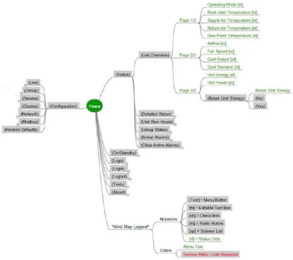
flowchart
graph TD
    A["Home"] --> B["(Configuration)"]
    A --> C["(Status)"]
    A --> D["*Mind Map Legend*"]
    A --> E["(*Mind Map Legend*)"]
    A --> F["Colors"]
    C --> G["(Unit Overview)"]
    C --> H["(On/Standby)"]
    C --> I["(Tests)"]
    C --> J["(About)"]
    C --> K["(Group Status)"]
    C --> L["(Active Alarms)"]
    C --> M["(Clear Active Alarms)"]
    C --> N["(Detailed Status)"]
    C --> O["(Detailed Status)"]
    C --> P["(On/Standby)"]
    G --> Q["Page 1/3"]
    Q --> R["Operating Mode [st"]]
    Q --> S["Rack Inlet Temperature [st"]]
    Q --> T["Supply Air Temperature [st"]]
    Q --> U["Return Air Temperature [st"]]
    Q --> V["Crew Point Temperature [st"]]
    G --> W["Airflow [st"]]
    W --> X["Fair Speed [st"]]
    W --> Y["Cool Output [st"]]
    W --> Z["Cool Demand [st"]]
    G --> AA["Page 2/3"]
    AA --> AB["Unit Energy [st"]]
    AA --> AC["Unit Power [st"]]
    AA --> AD["(Reset Unit Energy)"]
    AD --> AE["(No)"]
    AD --> AF["(Yes)"]
    G --> AG["Notations"]
    AG --> AH["(Text) = Menu Button"]
    AG --> AI["[tb"] = Editable Text Box]
    AG --> AJ["[cb"] = Check Box]
    AG --> AK["[rb"] = Radio Button]
    AG --> AL["[sp"] = Spinner List]
    AG --> AM["[st"] = Status Only]
    G --> AN["Menu Text"]
    AN --> AO["Service Menu Code Required"]
Detailed Status
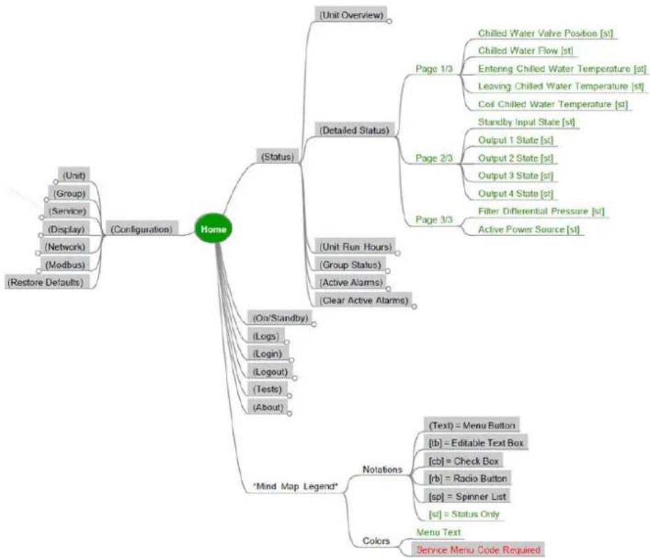
flowchart
graph TD
    A["Home"] --> B["(Configuration)"]
    A --> C["(Status)"]
    A --> D["*Mind Map Legend"]
    A --> E["Colors"]
    B --> B1["(Unit)"]
    B --> B2["(Group)"]
    B --> B3["(Service)"]
    B --> B4["(Display)"]
    B --> B5["(Network)"]
    B --> B6["(Modbus)"]
    B --> B7["(Restore Defaults)"]
    C --> C1["(Unit Overview)"]
    C --> C2["(Detailed Status)"]
    C --> C3["(On/Standby)"]
    C --> C4["(Logs)"]
    C --> C5["(Login)"]
    C --> C6["(Logout)"]
    C --> C7["(Tests)"]
    C --> C8["(About)"]
    C --> D
    D --> D1["(Chilled Water Valve Position [st"]]
    D --> D2["Chilled Water Flow [st"]]
    D --> D3["Entering Chilled Water Temperature [st"]]
    D --> D4["Leaving Chilled Water Temperature [st"]]
    D --> D5["Coil Chilled Water Temperature [st"]]
    C --> C6
    C --> C7
    C --> C8
    C --> C9["Page 1/3"]
    C --> C10["Page 2/3"]
    C --> C11["Page 3/3"]
    C --> C12["Output 1 State [st"]]
    C --> C13["Output 2 State [st"]]
    C --> C14["Output 3 State [st"]]
    C --> C15["Output 4 State [st"]]
    C --> C16["Filter Differential Pressure [st"]]
    C --> C17["Active Power Source [st"]]
Unit Run Hours Status
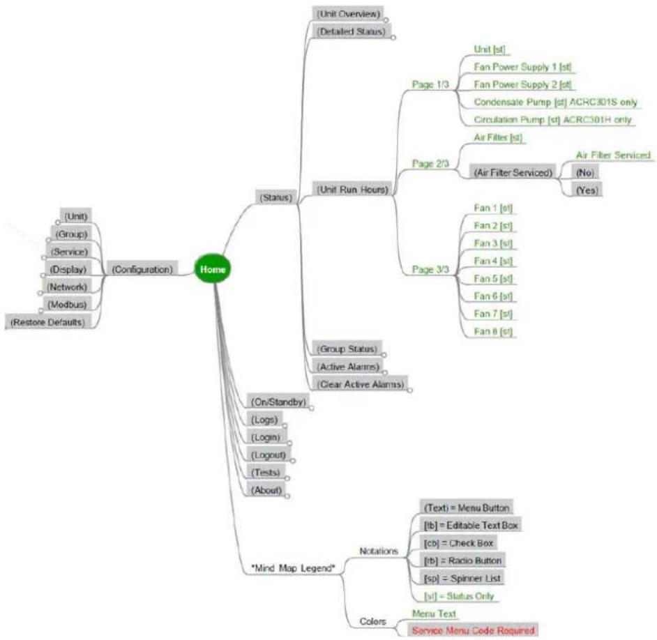
flowchart
graph TD
    A["Home"] --> B["(Configuration)"]
    A --> C["(Status)"]
    A --> D["*Mind Map Legend*"]
    A --> E["Colors"]
    B --> B1["(Unit)"]
    B --> B2["(Group)"]
    B --> B3["(Service)"]
    B --> B4["(Display)"]
    B --> B5["(Network)"]
    B --> B6["(Modbus)"]
    B --> B7["(Restore Defaults)"]

    C --> C1["(Unit Overview)"]
    C --> C2["(Detailed Status)"]
    C --> C3["(Unit Run Hours)"]
    C3 --> C31["Page 1/3"]
    C3 --> C32["Air Filter [st"]]
    C3 --> C33["(Air Filter Serviced)"]
    C33 --> C331["(No)"]
    C33 --> C332["(Yes)"]

    D --> D1["(On/Standby)"]
    D --> D2["(Logs)"]
    D --> D3["(Login)"]
    D --> D4["(Logout)"]
    D --> D5["(Tests)"]
    D --> D6["(About)"]

    E --> E1["(Text = Menu Button"]
    E --> E2["[tb"] = Editable Text Box]
    E --> E3["[cb"] = Check Box]
    E --> E4["[rb"] = Radio Button]
    E --> E5["[sp"] = Spinner List]
    E --> E6["[sI"] = Status Only]

    F["Notations"] --> F1["(Text = Menu Button"]
    F --> F2["[tb"] = Editable Text Box]
    F --> F3["[cb"] = Check Box]
    F --> F4["[rb"] = Radio Button]
    F --> F5["[sp"] = Spinner List]
    F --> F6["[sI"] = Status Only]

    G["Menu Text Service Menu Code Required"]
Group Status
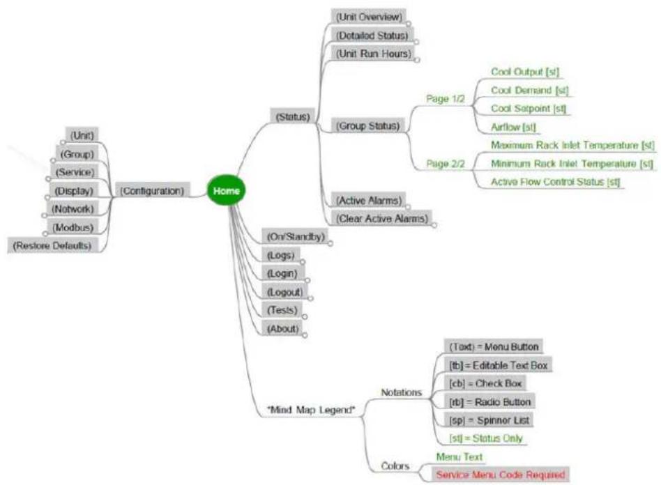
flowchart
graph TD
    A["Home"] --> B["(Configuration)"]
    A --> C["(Status)"]
    A --> D["Mind Map Legend"]
    A --> E["Colors"]

    B --> B1["(Unit)"]
    B --> B2["(Group)"]
    B --> B3["(Service)"]
    B --> B4["(Display)"]
    B --> B5["(Network)"]
    B --> B6["(Modbus)"]
    B --> B7["(Restore Defaults)"]

    C --> C1["(Unit Overview)"]
    C --> C2["(Detailed Status)"]
    C --> C3["(Unit Run Hours)"]

    C --> C4["(Group Status)"]
    C4 --> C4a["Page 1/2"]
    C4 --> C4b["Page 2/2"]

    C4 --> C4c["Active Alarms"]
    C4 --> C4d["Clear Active Alarms"]

    D --> D1["(On/Standby)"]
    D --> D2["(Logs)"]
    D --> D3["(Login)"]
    D --> D4["(Logout)"]
    D --> D5["(Tests)"]
    D --> D6["(About)"]


    E --> E1["Notations"]
    E1 --> E1a["(Text) = Monu Button"]
    E1 --> E1b["[tb"] = Editable Text Box]
    E1 --> E1c["[cb"] = Check Box]
    E1 --> E1d["[rb"] = Radio Button]
    E1 --> E1e["[sp"] = Spinner List]
    E1 --> E1f["[st"] = Status Only]

    E --> E2["Colors"]
    E2 --> E2a["Menu Text"]
    E2 --> E2b["Service Menu Code Required"]

    style A fill:#90EE90,stroke:#333
Active Alarms Status
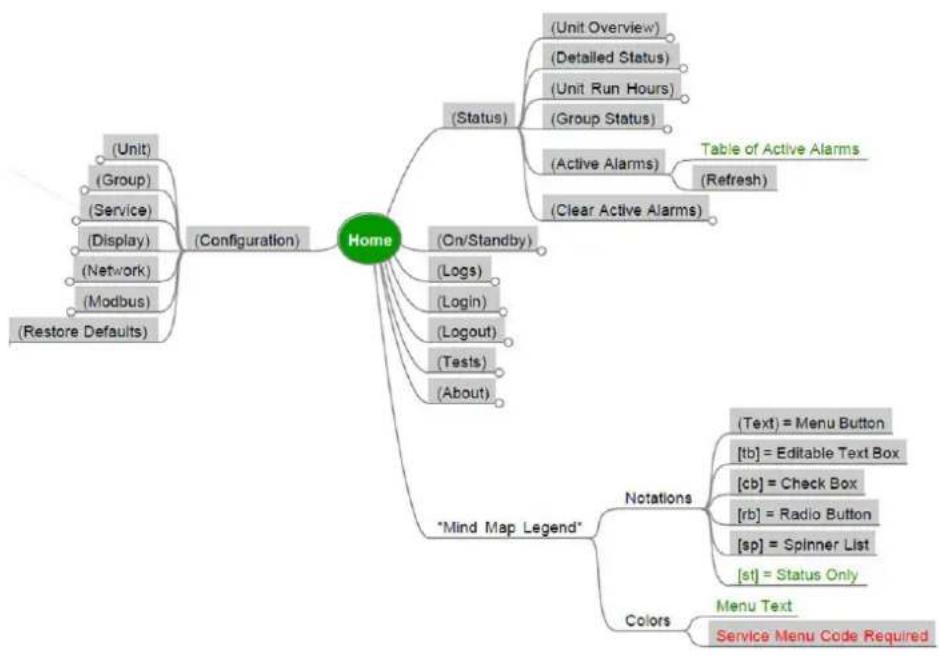
flowchart
graph TD
    A["Home"] --> B["(Configuration)"]
    A --> C["(On/Standby)"]
    A --> D["Table of Active Alarms (Refresh)"]
    A --> E["Notations"]
    A --> F["Colors"]
    B --> G["(Unit)"]
    B --> H["(Group)"]
    B --> I["(Service)"]
    B --> J["(Display)"]
    B --> K["(Network)"]
    B --> L["(Modbus)"]
    B --> M["(Restore Defaults)"]
    C --> N["(Status)"]
    C --> O["(Logs)"]
    C --> P["(Login)"]
    C --> Q["(Logout)"]
    C --> R["(Tests)"]
    C --> S["(About)"]
    D --> T["(Text) = Menu Button"]
    D --> U["[tb"] = Editable Text Box]
    D --> V["[cb"] = Check Box]
    D --> W["[rb"] = Radio Button]
    D --> X["[sp"] = Spinner List]
    D --> Y["[st"] = Status Only]
    F --> Z["Menu Text"]
    F --> AA["Service Menu Code Required"]
Clear Active Alarms Status
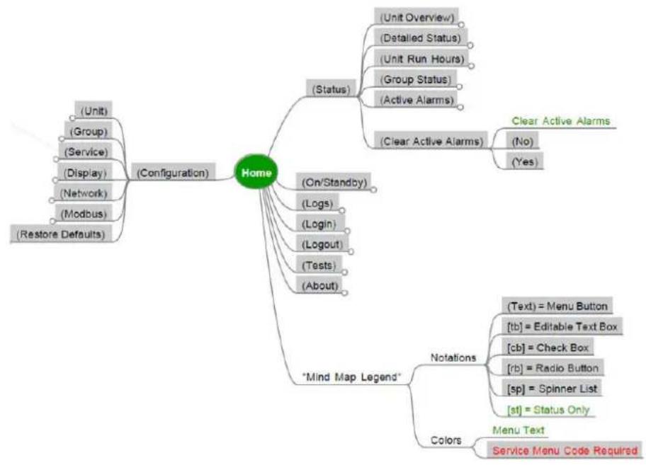
flowchart
graph TD
    A["Home"] --> B["(Configuration)"]
    A --> C["(Status)"]
    A --> D["Mind Map Legend"]
    A --> E["Colors"]
    C --> F["(Unit Overview)"]
    C --> G["(Detailed Status)"]
    C --> H["(Unit Run Hours)"]
    C --> I["(Group Status)"]
    C --> J["(Active Alarms)"]
    C --> K["(Clear Active Alarms)"]
    K --> L["Clear Active Alarms"]
    K --> M["(No)"]
    K --> N["(Yes)"]
    D --> O["(On/Standby)"]
    D --> P["(Logs)"]
    D --> Q["(Login)"]
    D --> R["(Logout)"]
    D --> S["(Tests)"]
    D --> T["(About)"]
    O --> U["(Text) = Menu Button"]
    O --> V["[tb"] = Editable Text Box]
    O --> W["[cb"] = Check Box]
    O --> X["[rb"] = Radio Button]
    O --> Y["[sp"] = Spinner List]
    O --> Z["[st"] = Status Only]
    D --> AA["Colors"]
    AA --> AB["Menu Text"]
    AA --> AC["Service Menu Code Required"]
On/Standby-Command to Standby
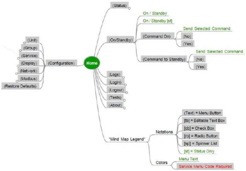
flowchart
graph TD
    A["Home"] --> B["(Configuration)"]
    A --> C["(Status)"]
    A --> D["(On/Standby)"]
    A --> E["(Command On)"]
    A --> F["(Command to Standby)"]
    D --> G["On / Standby"]
    D --> H["On / Standby [st"]]
    D --> I["(Command On)"]
    I --> J["Send Selected Command"]
    I --> K["(No)"]
    I --> L["(Yes)"]
    F --> M["Send Selected Command"]
    F --> N["(No)"]
    F --> O["(Yes)"]
    A --> P["(Logs)"]
    P --> Q["(Login)"]
    P --> R["(Logout)"]
    P --> S["(Tests)"]
    P --> T["(About)"]
    A --> U["*Mind Map Legend*"]
    U --> V["(Text) = Menu Button"]
    U --> W["[tb"] = Editable Text Box]
    U --> X["[cb"] = Check Box]
    U --> Y["[rb"] = Radio Button]
    U --> Z["[sp"] = Spinner List]
    U --> AA["[st"] = Status Only]
    A --> AB["Colors"]
    AB --> AC["Menu Text"]
    AB --> AD["Service Menu Code Required"]
Logs Events-Export Data
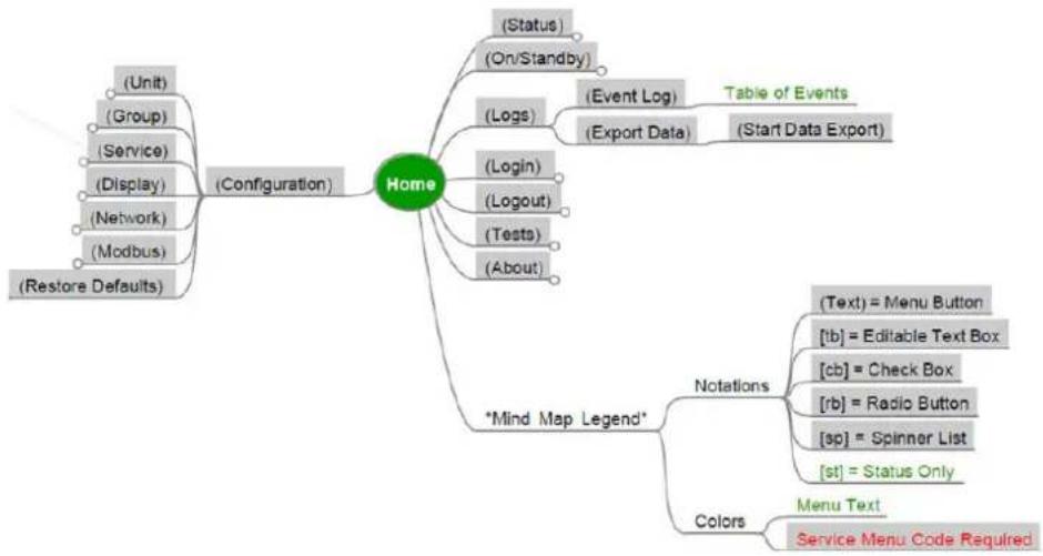
flowchart
graph TD
    A["Home"] --> B["(Configuration)"]
    A --> C["Table of Events"]
    A --> D["Notations"]
    A --> E["Colors"]
    D --> F["(Text) = Menu Button"]
    D --> G[""[tb"] = Editable Text Box"]
    D --> H[""[cb"] = Check Box"]
    D --> I[""[rb"] = Radio Button"]
    D --> J[""[sp"] = Spinner List"]
    D --> K[""[st"] = Status Only"]
    E --> L["Menu Text"]
    E --> M["Service Menu Code Required"]
    A --> N["(Unit)"]
    A --> O["(Group)"]
    A --> P["(Service)"]
    A --> Q["(Display)"]
    A --> R["(Network)"]
    A --> S["(Modbus)"]
    A --> T["(Restore Defaults)"]
    A --> U["(Status)"]
    A --> V["(On/Standby)"]
    A --> W["(Logs)"]
    W --> X["(Event Log)"]
    W --> Y["(Export Data)"]
    W --> Z["(Start Data Export)"]
    A --> AA["(Login)"]
    AA --> AB["(Logout)"]
    AA --> AC["(Tests)"]
    AA --> AD["(About)"]
    A --> AE["*Mind Map Legend*"]
Login/Logout
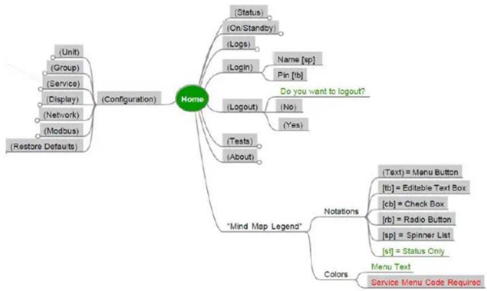
flowchart
graph TD
    A["Home"] --> B["(Configuration)"]
    A --> C["Mind Map Legend"]
    A --> D["Colors"]
    D --> E["Notations"]
    D --> F["Colors"]
    E --> G["(Text) = Menu Button"]
    E --> H["[tb"] = Editable Text Box]
    E --> I["[cb"] = Check Box]
    E --> J["[rb"] = Radio Button]
    E --> K["[sp"] = Spinner List]
    E --> L["[sf"] = Status Only]
    D --> M["Colors"]
    M --> N["Menu Text"]
    M --> O["Service Menu Code Required"]
    A --> P["(Restore Defaults)"]
    A --> Q["(Network)"]
    A --> R["(Display)"]
    A --> S["(Service)"]
    A --> T["(Group)"]
    A --> U["(Unit)"]
    A --> V["(Logs)"]
    A --> W["(Login)"]
    A --> X["(Logout)"]
    X --> Y["Do you want to logout?"]
    A --> Z["(Tests)"]
    A --> AA["(About)"]
Tests/Display/Display Calibration
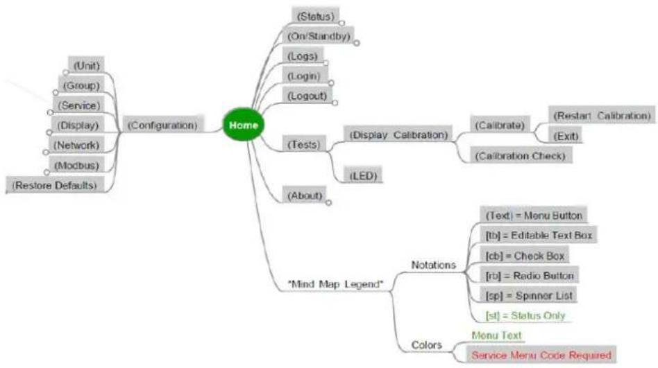
flowchart
graph TD
    A["Home"] --> B["(Configuration)"]
    A --> C["(Tests)"]
    A --> D["(Display Calibration)"]
    A --> E["(*Mind Map Legend* *"]
    A --> F["(*Amounts)"]
    A --> G["(*Amounts)"]
    A --> H["(*Amounts)"]
    A --> I["(*Amounts)"]
    A --> J["(*Amounts)"]
    A --> K["(*Amounts)"]
    A --> L["(*Amounts)"]
    A --> M["(*Amounts)"]
    A --> N["(*Amounts)"]
    A --> O["(*Amounts)"]
    A --> P["(*Amounts)"]
    A --> Q["(*Amounts)"]
    A --> R["(*Amounts)"]
    A --> S["(*Amounts)"]
    A --> T["(*Amounts)"]
    A --> U["(*Amounts)"]
    A --> V["(*Amounts)"]
    A --> W["(*Amounts)"]
    A --> X["(*Amounts)"]
    A --> Y["(*Amounts)"]
    A --> Z["(*Amounts)"]
    A --> AA["(*Amounts)"]
    A --> AB["(*Amounts)"]
    A --> AC["(*Amounts)"]
    A --> AD["(*Amounts)"]
    A --> AE["(*Amounts)"]
    A --> AF["(*Amounts)"]
    A --> AG["(*Amounts)"]
    A --> AH["(*Amounts)"]
    A --> AI["(*Amounts)"]
    A --> AJ["(*Amounts)"]
    A --> AK["(*Amounts)"]
    A --> AL["(*Amounts)"]
    A --> AM["(*Amounts)"]
    A --> AN["(*Amounts)"]
    A --> AO["(*Amounts)"]
    A --> AP["(*Amounts)"]
    A --> AQ["(*Amounts)"]
    A --> AR["(*Amounts)"]
    A --> AS["(*Amounts)"]
    A --> AT["(*Amounts)"]
    A --> AU["(*Amounts)"]
    A --> AV["(*Amounts)"]
    A --> AW["(*Amounts)"]
    A --> AX["(*Amounts)"]
    A --> AY["(*Amounts)"]
    A --> AZ["(*Amounts)"]
    A --> BA["(*Amounts)"]
    A --> BB["(*Amounts)"]
    A --> BC["(*Amounts)"]
    A --> BD["(*Amounts)"]
    A --> BE["(*Amounts)"]
    A --> BF["(*Amounts)"]
    A --> BG["(*Amounts)"]
    A --> BH["(*Amounts)"]
    A --> BI["(*Amounts)"]
    A --> BJ["(*Amounts)"]
    A --> BK["(*Amounts)"]
    A --> BL["(*Amounts)"]
    A --> BM["(*Amounts)"]
    A --> BN["(*Amounts)"]
    A --> BO["(*Amounts)"]
    A --> BP["(*Amounts)"]
    A --> BQ["(*Amounts)"]
    A --> BR["(*Amounts)"]
    A --> BS["(*Amounts)"]
    A --> BT["(*Amounts)"]
    A --> BU["(*Amounts)"]
    A --> BV["(*Amounts)"]
    A --> BW["(*Amounts)"]
    A --> BX["(*Amounts)"]
    A --> BY["(*Amounts)"]
    A --> BZ["(*Amounts)"]
About IPv4 Network
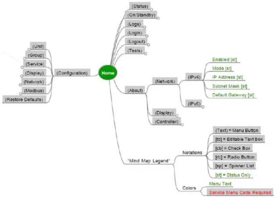
flowchart
graph TD
    A["Home"] --> B["(Configuration)"]
    A --> C["(*Mind Map Legend*)"]
    A --> D["(*Amounts)"]
    A --> E["(*Status)"]
    A --> F["(*Amounts)"]
    A --> G["(*Amounts)"]
    A --> H["(*Amounts)"]
    A --> I["(*Amounts)"]
    A --> J["(*Amounts)"]
    A --> K["(*Amounts)"]
    A --> L["(*Amounts)"]
    A --> M["(*Amounts)"]
    A --> N["(*Amounts)"]
    A --> O["(*Amounts)"]
    A --> P["(*Amounts)"]
    A --> Q["(*Amounts)"]
    A --> R["(*Amounts)"]
    A --> S["(*Amounts)"]
    A --> T["(*Amounts)"]
    A --> U["(*Amounts)"]
    A --> V["(*Amounts)"]
    A --> W["(*Amounts)"]
    A --> X["(*Amounts)"]
    A --> Y["(*Amounts)"]
    A --> Z["(*Amounts)"]
    A --> AA["(*Amounts)"]
    A --> AB["(*Amounts)"]
    A --> AC["(*Amounts)"]
    A --> AD["(*Amounts)"]
    A --> AE["(*Amounts)"]
    A --> AF["(*Amounts)"]
    A --> AG["(*Amounts)"]
    A --> AH["(*Amounts)"]
    A --> AI["(*Amounts)"]
    A --> AJ["(*Amounts)"]
    A --> AK["(*Amounts)"]
    A --> AL["(*Amounts)"]
    A --> AM["(*Amounts)"]
    A --> AN["(*Amounts)"]
    A --> AO["(*Amounts)"]
    A --> AP["(*Amounts)"]
    A --> AQ["(*Amounts)"]
    A --> AR["(*Amounts)"]
    A --> AS["(*Amounts)"]
    A --> AT["(*Amounts)"]
    A --> AU["(*Amounts)"]
    A --> AV["(*Amounts)"]
    A --> AW["(*Amounts)"]
    A --> AX["(*Amounts)"]
    A --> AY["(*Amounts)"]
    A --> AZ["(*Amounts)"]
    A --> BA["(*Amounts)"]
    A --> BB["(*Amounts)"]
    A --> BC["(*Amounts)"]
    A --> BD["(*Amounts)"]
    A --> BE["(*Amounts)"]
    A --> BF["(*Amounts)"]
    A --> BG["(*Amounts)"]
    A --> BH["(*Amounts)"]
    A --> BI["(*Amounts)"]
    A --> BJ["(*Amounts)"]
    A --> BK["(*Amounts)"]
    A --> BL["(*Amounts)"]
    A --> BM["(*Amounts)"]
    A --> BN["(*Amounts)"]
    A --> BO["(*Amounts)"]
    A --> BP["(*Amounts)"]
    A --> BQ["(*Amounts)"]
    A --> BR["(*Amounts)"]
    A --> BS["(*Amounts)"]
    A --> BT["(*Amounts)"]
    A --> BU["(*Amounts)"]
    A --> BV["(*Amounts)"]
    A --> BW["(*Amounts)"]
    A --> BX["(*Amounts)"]
    A --> BY["(*Amounts)"]
    A --> BZ["(*Amounts)"]
About IPv6 Network
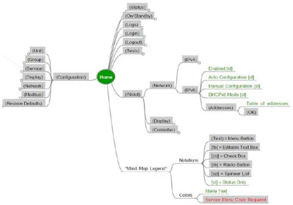
flowchart
graph TD
    A["Home"] --> B["(Configuration)"]
    A --> C["(Status)"]
    A --> D["(On/Standby)"]
    A --> E["(Logs)"]
    A --> F["(Login)"]
    A --> G["(Logout)"]
    A --> H["(Tests)"]
    A --> I["(About)"]
    I --> J["(Network)"]
    I --> K["(Display)"]
    I --> L["(Controller)"]
    A --> M["IPV4"]
    A --> N["IPV6"]
    A --> O["Table of addresses"]
    O --> P["(OK)"]
    A --> Q["*Mind Map Legend*"]
    Q --> R["Notations"]
    R --> S["(Text) = Menu Button"]
    R --> T["[tb"] = Editable Text Box]
    R --> U["[cb"] = Check Box]
    R --> V["[rb"] = Radio Button]
    R --> W["[sp"] = Spinner List]
    R --> X["[sl"] = Status Only]
    A --> Y["Colors"]
    Y --> Z["Menu Text"]
    Y --> AA["Service Menu Code Required"]
About Display Device
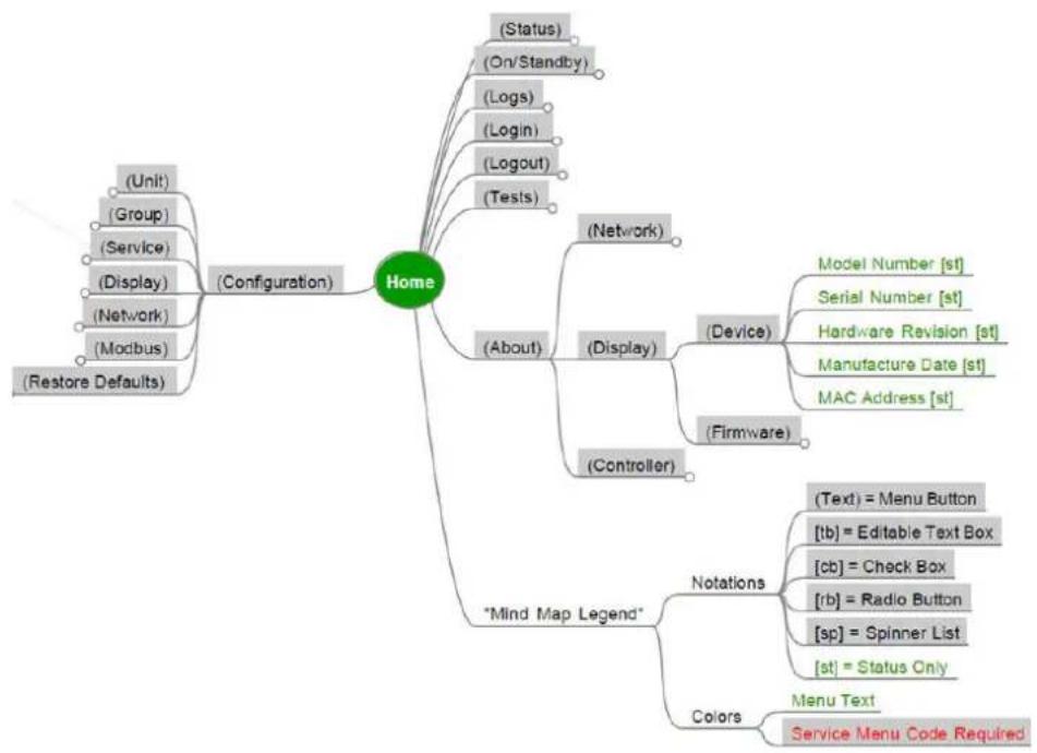
flowchart
graph TD
    A["Home"] --> B["(Configuration)"]
    A --> C["(About)"]
    A --> D["Mind Map Legend"]
    A --> E["Colors"]

    B --> B1["(Unit)"]
    B --> B2["(Group)"]
    B --> B3["(Service)"]
    B --> B4["(Display)"]
    B --> B5["(Network)"]
    B --> B6["(Modbus)"]
    B --> B7["(Restore Defaults)"]

    C --> C1["(Status)"]
    C --> C2["(On/Standby)"]
    C --> C3["(Logs)"]
    C --> C4["(Login)"]
    C --> C5["(Logout)"]
    C --> C6["(Tests)"]

    C --> C7["(Network)"]
    C --> C8["(Display)"]
    C --> C9["(Controller)"]

    C8 --> C91["(Device)"]
    C91 --> C91a["Model Number [st"]]
    C91 --> C91b["Serial Number [st"]]
    C91 --> C91c["Hardware Revision [st"]]
    C91 --> C91d["Manufacture Date [st"]]
    C91 --> C91e["MAC Address [st"]]

    C91 --> C91f["Firmware"]

    D --> D1["Notations"]
    D --> D2["Colors"]


    D1 --> D1a["(Text) = Menu Button"]
    D1 --> D1b["[tb"] = Editable Text Box]
    D1 --> D1c["[cb"] = Check Box]
    D1 --> D1d["[rb"] = Radio Button]
    D1 --> D1e["[sp"] = Spinner List]
    D1 --> D1f["[st"] = Status Only]

    D2 --> D2a["Menu Text"]
    D2 --> D2b["Service Menu Code Required"]
About Display Firmware
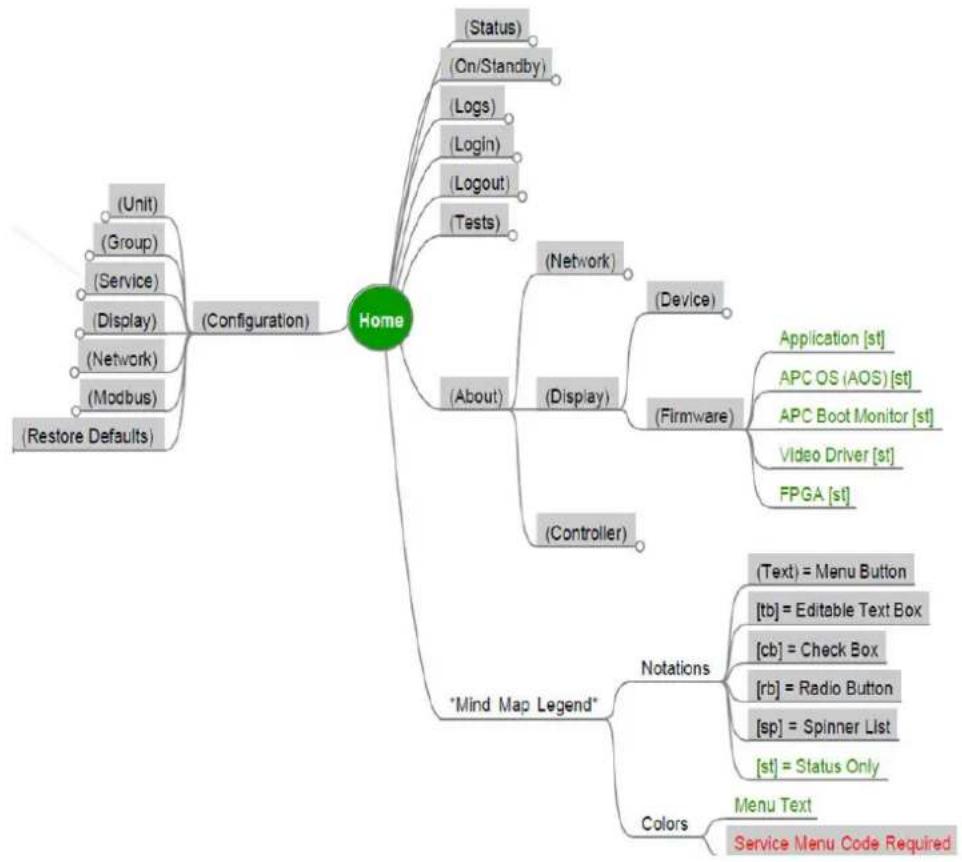
flowchart
graph TD
    A["Home"] --> B["(Configuration)"]
    A --> C["(*Mind Map Legend*)"]
    A --> D["(*About)"]
    A --> E["(*Controls)"]
    A --> F["(*Status)"]
    A --> G["(*Logout)"]
    A --> H["(*Tests)"]
    A --> I["(*Network)"]
    A --> J["(*Device)"]
    A --> K["(*Firmware)"]
    A --> L["(*Text) = Menu Button"]
    A --> M["(*rgb) = Check Box"]
    A --> N["(*rb) = Radio Button"]
    A --> O["(*sp) = Spinner List"]
    A --> P["(*st) = Status Only"]
    A --> Q["(*Storage)"] --> R["(*On/Standby)"]
    A --> S["(*Login)"] --> T["(*On/Standby)"]
    A --> U["(*Logout)"] --> V["(*On/Standby)"]
    A --> W["(*Tests)"] --> X["(*On/Standby)"]
    A --> Y["(*Services)"] --> Z["(*On/Standby)"]
    A --> AA["(*Services)"] --> AB["(*On/Standby)"]
    A --> AC["(*Services)"] --> AD["(*On/Standby)"]
About Controller
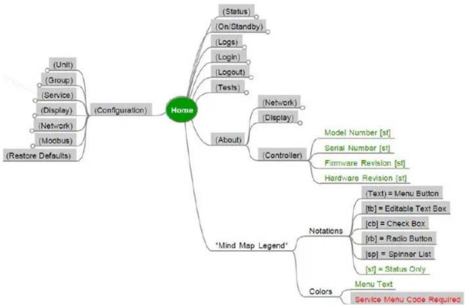
flowchart
graph TD
    A["Home"] --> B["(Configuration)"]
    A --> C["About"]
    A --> D["*Mind Map Legend*"]
    A --> E["Colors"]
    B --> F["(Unit)"]
    B --> G["(Group)"]
    B --> H["(Service)"]
    B --> I["(Display)"]
    B --> J["(Network)"]
    B --> K["(Modbus)"]
    B --> L["(Restore Defaults)"]
    C --> M["(Status)"]
    C --> N["(On/Standby)"]
    C --> O["(Logs)"]
    C --> P["(Login)"]
    C --> Q["(Logout)"]
    C --> R["(Tests)"]
    C --> S["(About)"]
    S --> T["(Network)"]
    S --> U["(Display)"]
    S --> V["(Controller)"]
    V --> W["Model Number [st"]]
    V --> X["Serial Number [st"]]
    V --> Y["Firmware Revision [st"]]
    V --> Z["Hardware Revision [st"]]
    V --> AA["Notations"]
    AA --> AB["(Text) = Menu Button"]
    AA --> AC["[tb"] = Editable Text Box]
    AA --> AD["[cb"] = Check Box]
    AA --> AE["[rb"] = Radio Button]
    AA --> AF["[sp"] = Spinner List]
    AA --> AG["[st"] = Status Only]]
    V --> AH["Colors"]
    AH --> AI["Menu Text"]
    AH --> AJ["Service Menu Code Required"]
Worldwide Customer Support
Customer support for this product is available at no charge in any of the following ways:
- Visit the Schneider Electric Web site to access documents in the Schneider Electric Knowledge Base and to submit customer support requests.
www.se.com (Corporate Headquarters)
Connect to localized Schneider Electric websites for specific countries, each of which provides customer support information.
www.se.com/support/
Get global support by searching the Schneider Electric Knowledge Base and using esupport.
- Contact the Schneider Electric Customer Support Center by telephone or e-mail. Go to www.se.com > Support > Contact Support to find contact information for country-specific centers.
For information on how to obtain local customer support, contact the representative or other distributors from whom you purchased your product.
Schneider Electric
As standards, specifications, and design change from time to time, please ask for confirmation of the information given in this publication.

- InRow® Chilled Water Air Conditioners (High Temperature)
- Legal Information
- CE
- Table of Contents
- Safety
- Important Safety Instructions — SAVE THESE INSTRUCTIONS
- ⚠️ DANGER
- ▲WARNING
- ▲CAUTION
- NOTICE
- Please Note
- Safety Notices for All Service Procedures
- HAZARD OF ELECTRIC SHOCK, EXPLOSION, OR ARC FLASH
- HAZARD OF ELECTRIC SHOCK
- HAZARD FROM MOVING PARTS
- TIPPING HAZARD
- UNEXPECTED START-UP OF EQUIPMENT
- HAZARD TO EQUIPMENT
- General Information
- Translation Reference
- Save These Instructions
- Manual Updates
- Cross-Reference Symbol Used in This Manual
- Audience
- Companion Manuals
- Network and Controls
- InRow Touchscreen and Wiring
- Controller Area Network (CAN) Diagram (A-Link ports)
- Active Flow Controllers (AFC)
- CAT 5 PINOUT
- Network Port
- Modbus
- Modbus Configuration—DIP Switch SW503
- Position Status Dips Switches Mode
- Output Relays and Standby Input
- Item Description Item Description
- Communication (Building Management System)
- Shutdown Input Contact and Alarm Output Contact
- Output Relays
- Standby Input
- Components Location
- Piping
- Communication
- Interface Connection
- Cooling Group
- Network Management Card to Customer LAN
- Network Management Card to StruxureWare™ for Data Centers
- Unit to Customer BMS
- Component Replacement
- Before You Start
- Powering down the unit
- Remove Doors and Panels
- Cleanable Air Filters
- Removal and Installation
- Control Actuator
- Removal
- Chilled Water Valve
- Installation
- Flow Meter-Electronics Module
- ENGAGE INTERLOCKS
- COOLANT SPILL
- EQUIPMENT DAMAGE
- Installing and Verifying Operation
- Dew Point Control Pump
- Removal with ACRC301H installed in-row
- ATS Relay
- Control Board
- Fan Assembly
- MOVING PARTS
- Fan Power Supply
- POWER SUPPLY CONFIGURATION
- Network Management Card
- Display Interface
- Temperature Sensors
- Updating the Firmware
- Item Description
- Overview
- Updating Procedure
- Generating Service Passcodes
- Dew Point Control Pump Programming
- Correct Settings
- Normal Operation
- Check/change the settings
- Changing text position
- Changing control mode
- Troubleshooting
- Appendix
- InRow Touchscreen Diagrams
- All Menus
- Home Menu
- Unit Threshold Configuration
- Unit Configuration
- Group Configuration
- Group Setpoints
- Display Preferences
- Service Code Configuration
- Login/Logout
- Tests/Display/Display Calibration
- About Controller
- Worldwide Customer Support
Brand : APC
Model : ACRC301H
Category : Air conditioner